Raytac MD85XXP1 Wireless Audio Module User Manual
Raytac Corp. Wireless Audio Module
UserManual.wiki
>
Raytac
>
MD85XXP1 User Manual
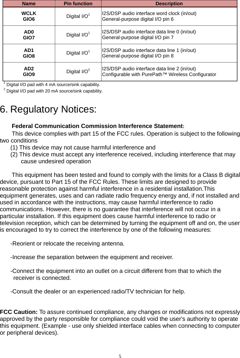
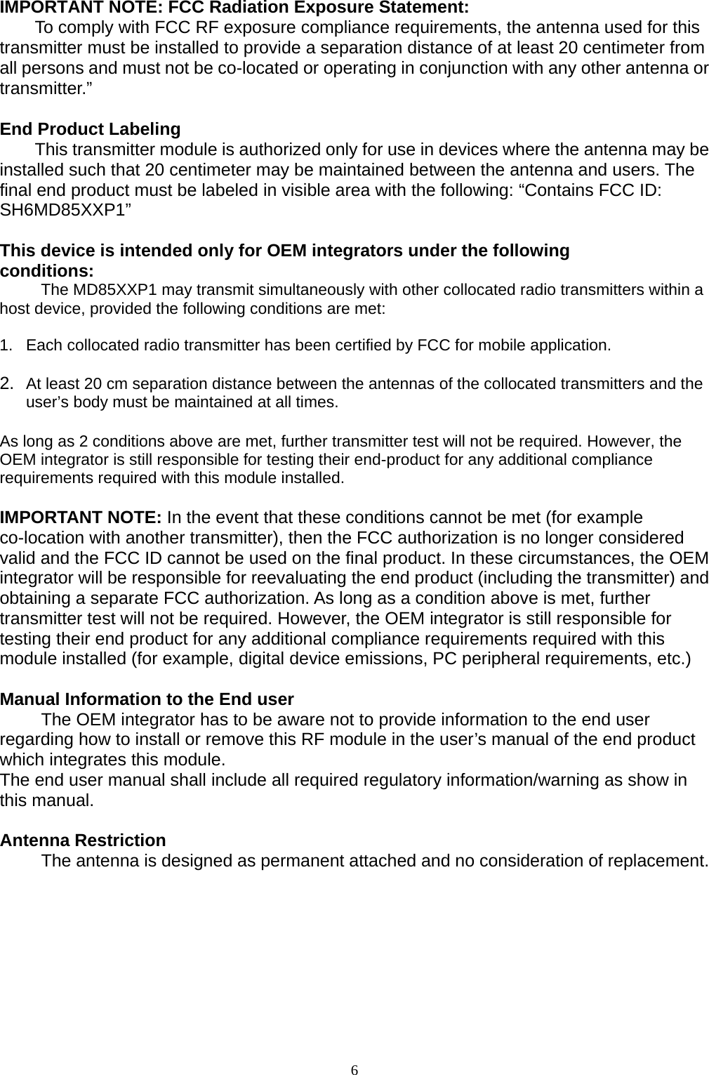
User Manaul REVISED
Navigation menu
Upload a User Manual
Namespaces
Wiki Guide
HTML
PDF
Info
Views
User Manual
Discussion / Help
Navigation