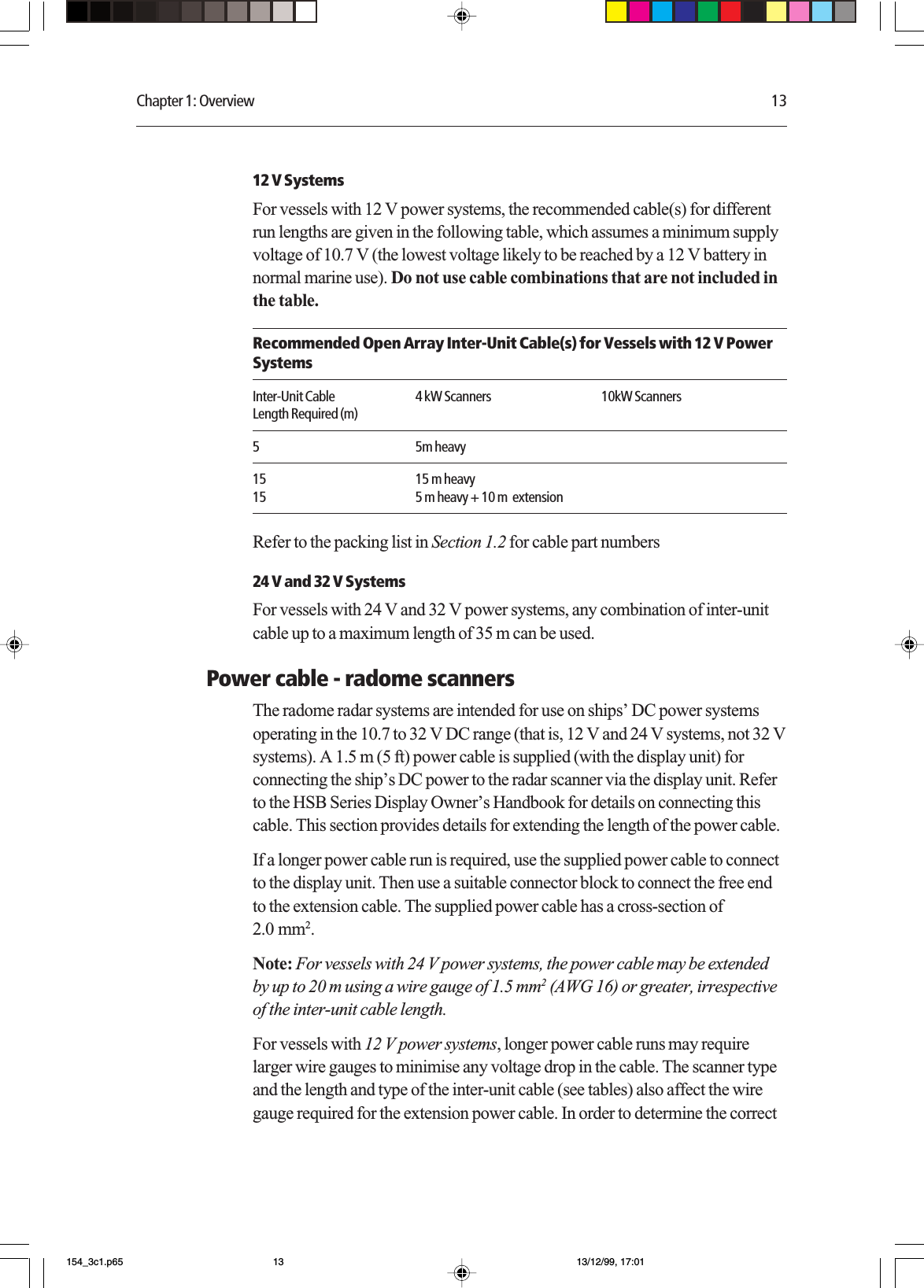
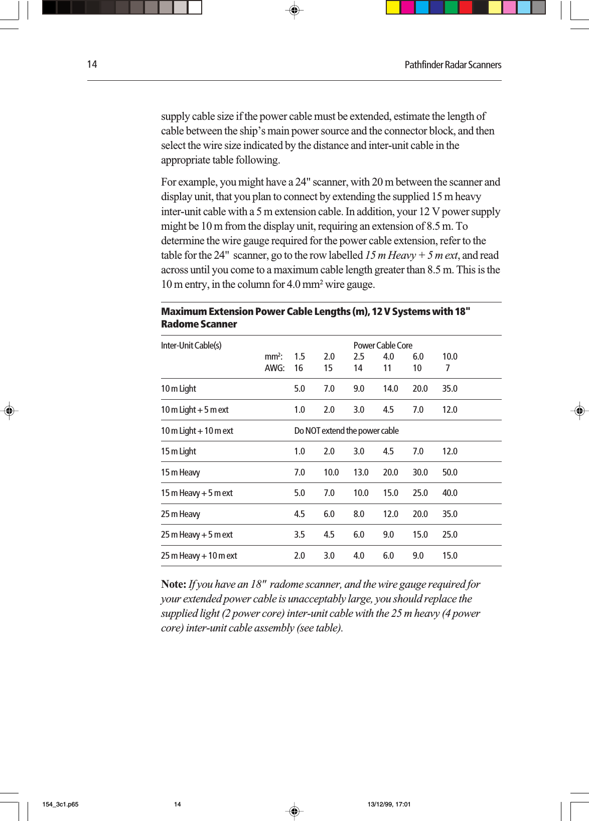
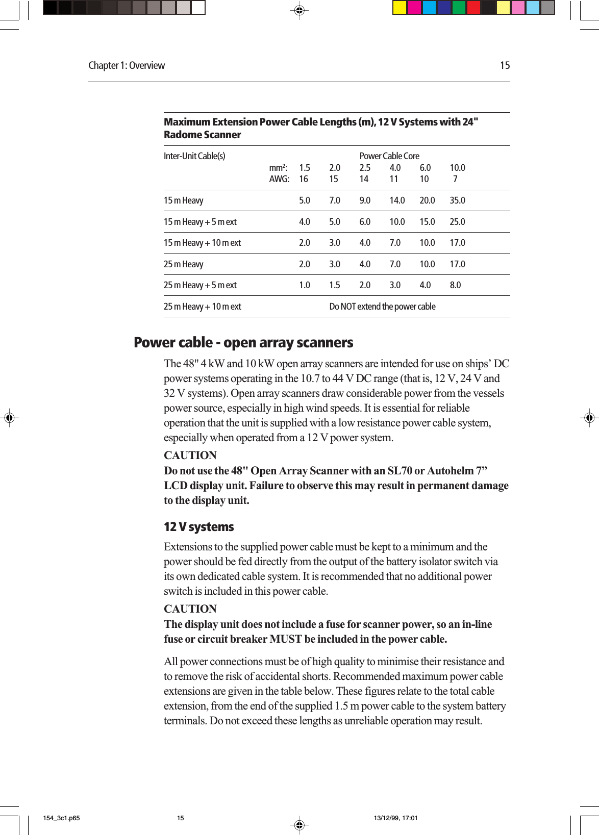
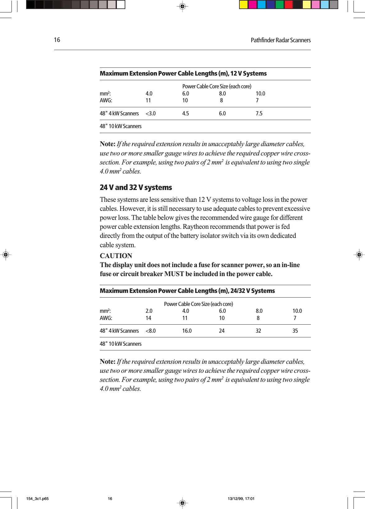
Raytheon Anschuetz High Seas MTX9 Leisure Marine Radar User Manual 154 3cvr p65
Raytheon Anschuetz GmbH High Seas Products Leisure Marine Radar 154 3cvr p65
UserManual.wiki
>
Raytheon Anschuetz High Seas
>
MTX9 User Manual
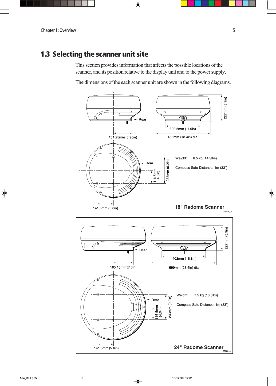
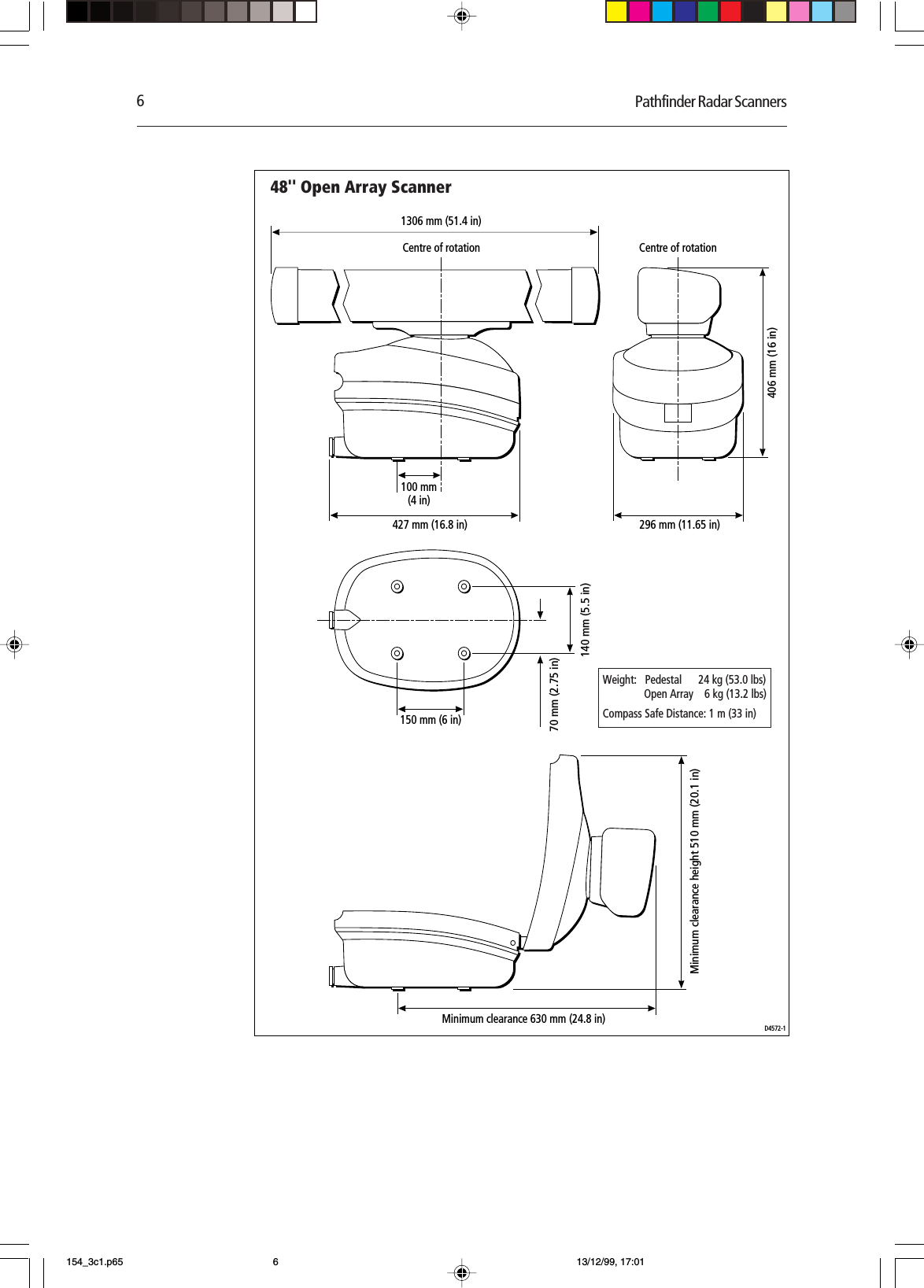
Owners Handbook
Navigation menu
Upload a User Manual
Namespaces
Wiki Guide
HTML
PDF
Info
Views
User Manual
Discussion / Help
Navigation