Raytheon IDS M3-UHF-450 100W UHF BASE STATION User Manual 3
JPS COMMUNICATIONS, INC. 100W UHF BASE STATION Users Manual 3
UserManual.wiki
>
Raytheon IDS
>
M3-UHF-450 User Manual
>
Users Manual 3
Contents
1.
Users Manual
2.
Users Manual 2
3.
Users Manual Switching Power Supply
4.
Users Manual UHF Power Amplifier
5.
Users Manual Maintenance
6.
Users Manual 3
Users Manual 3
Navigation menu
Upload a User Manual
Namespaces
Wiki Guide
HTML
PDF
Info
Views
User Manual
Discussion / Help
Navigation
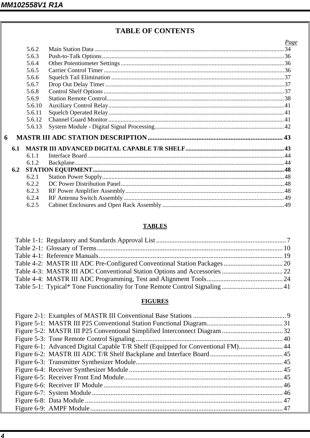
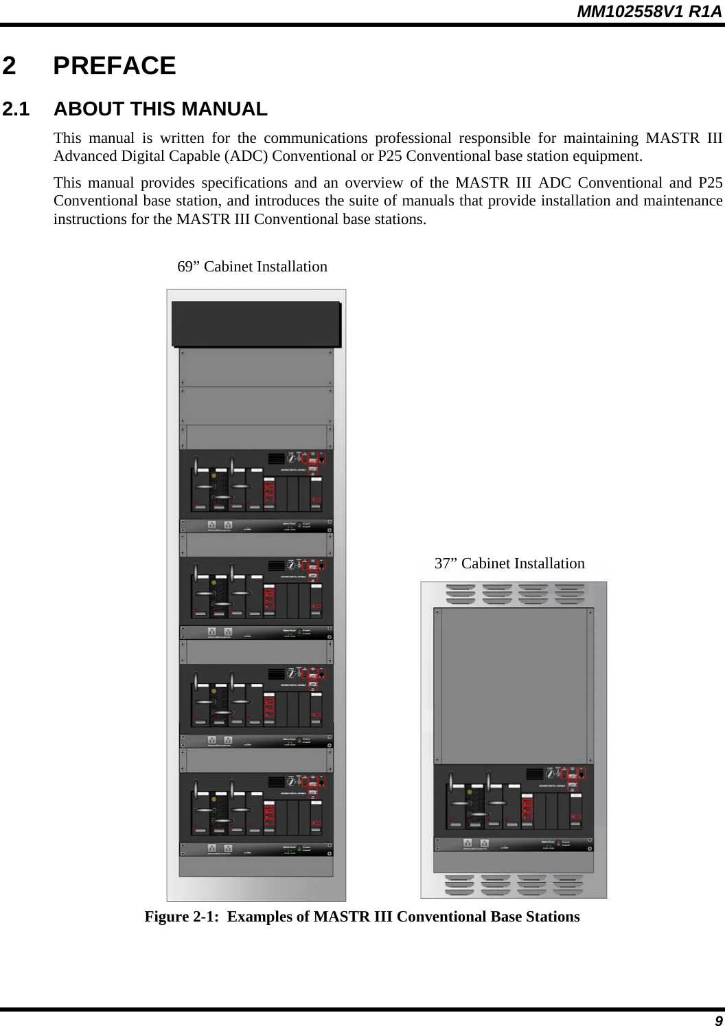
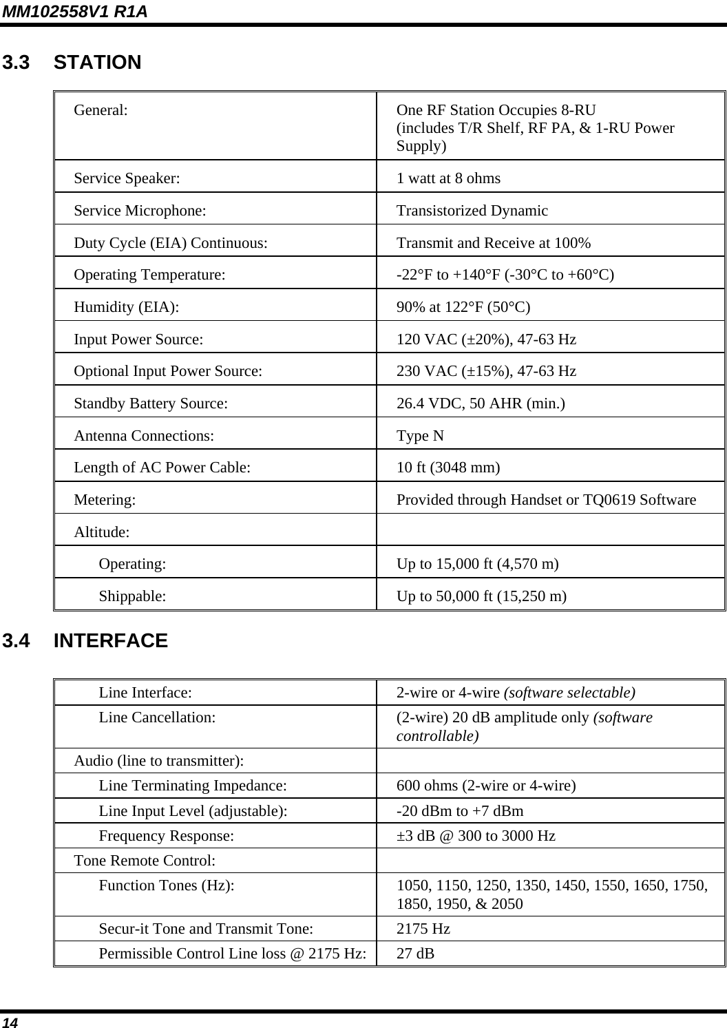
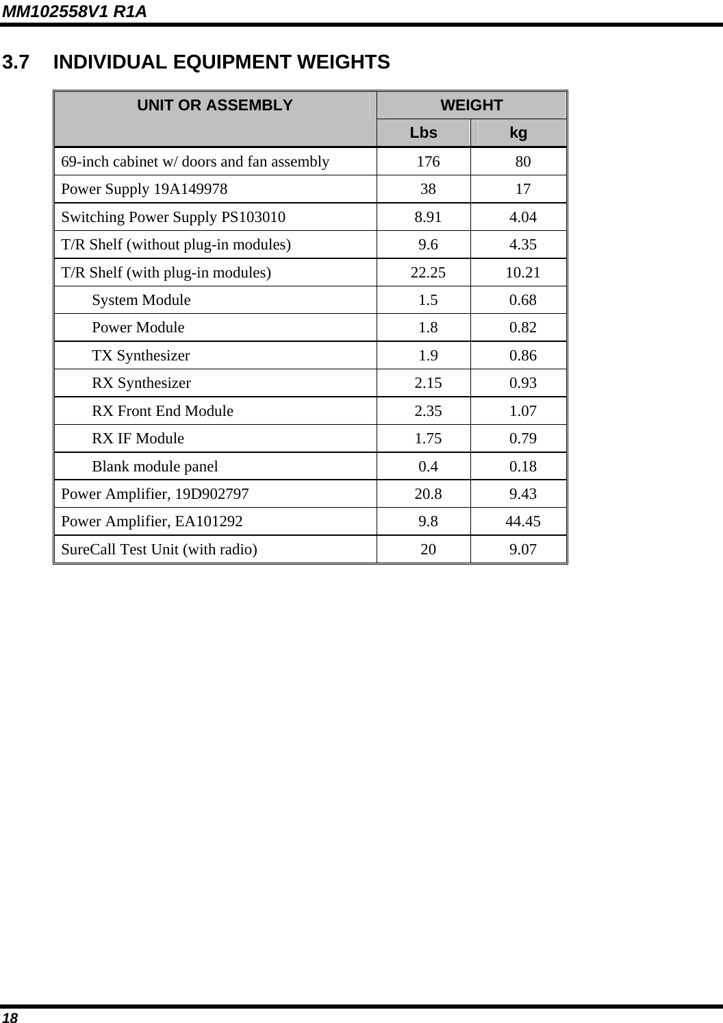
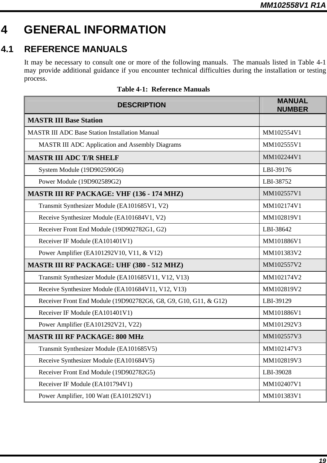
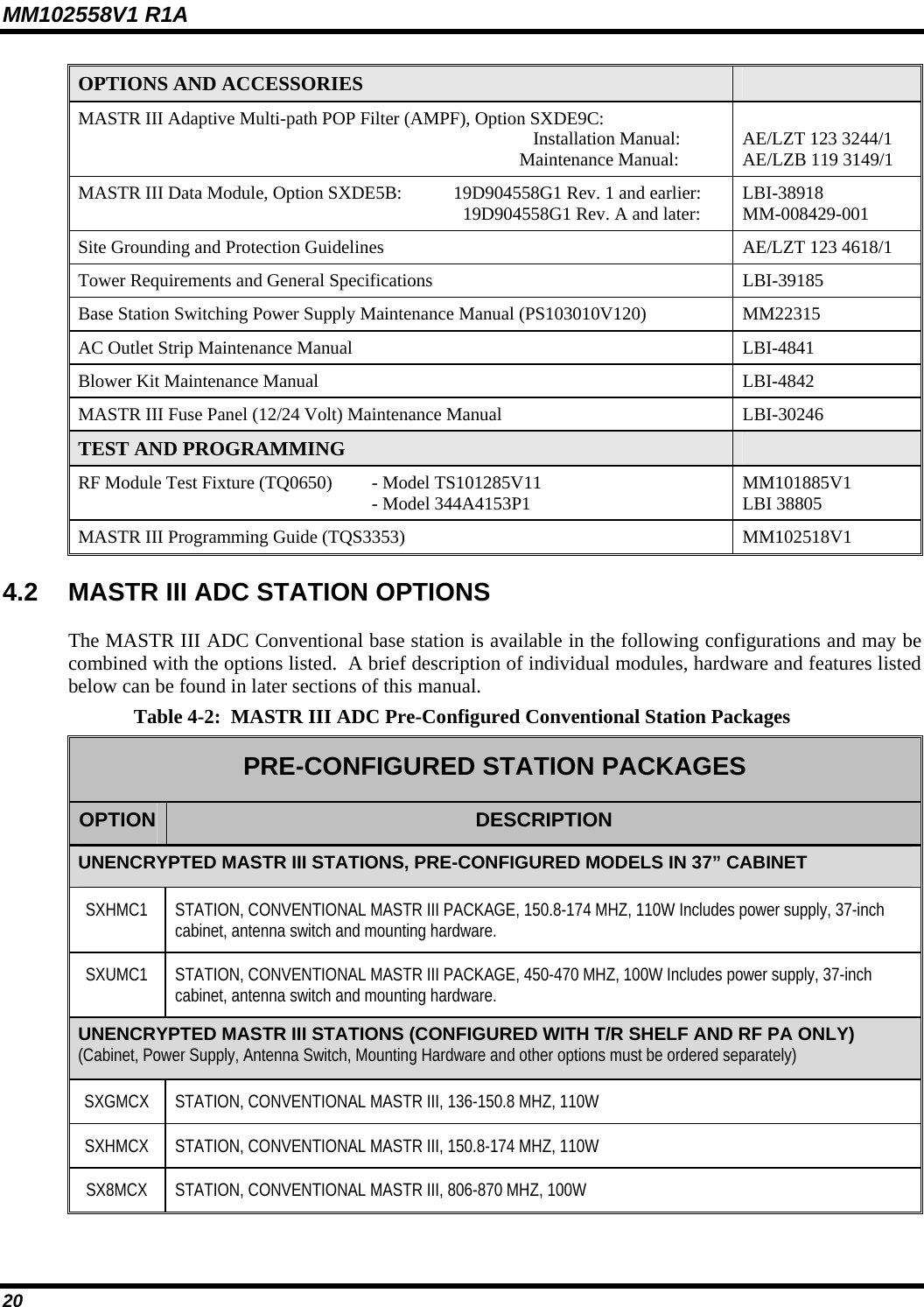
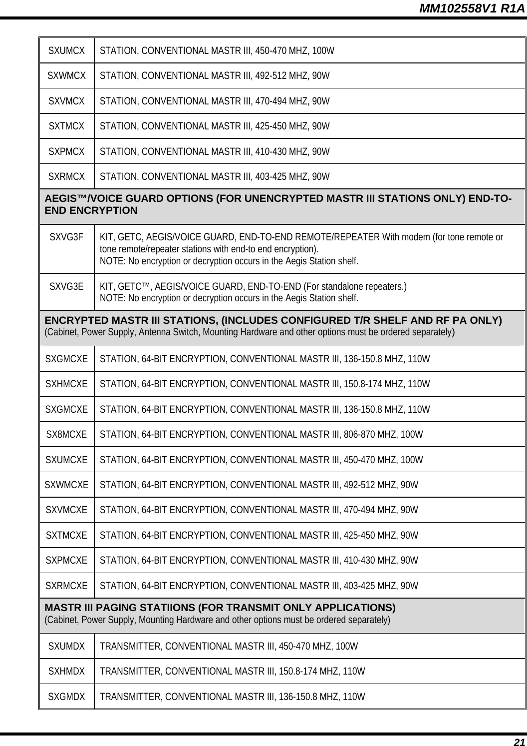
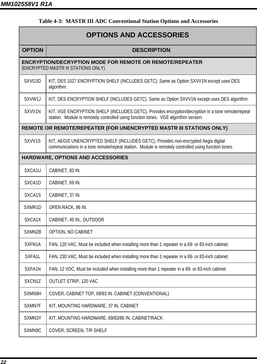
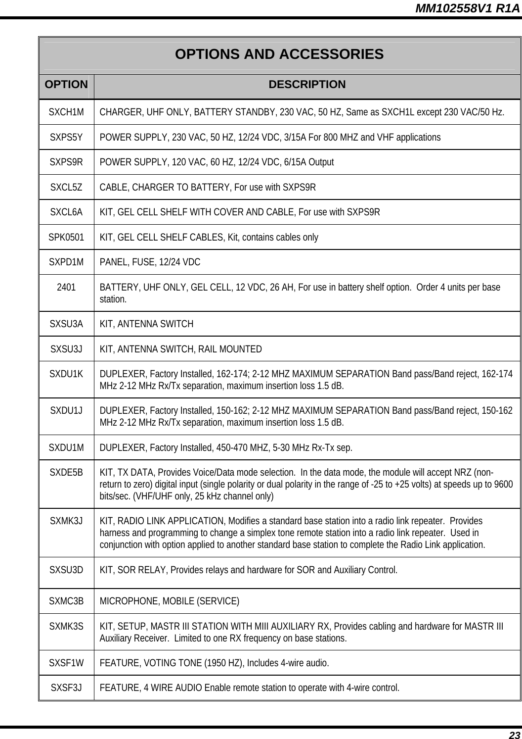
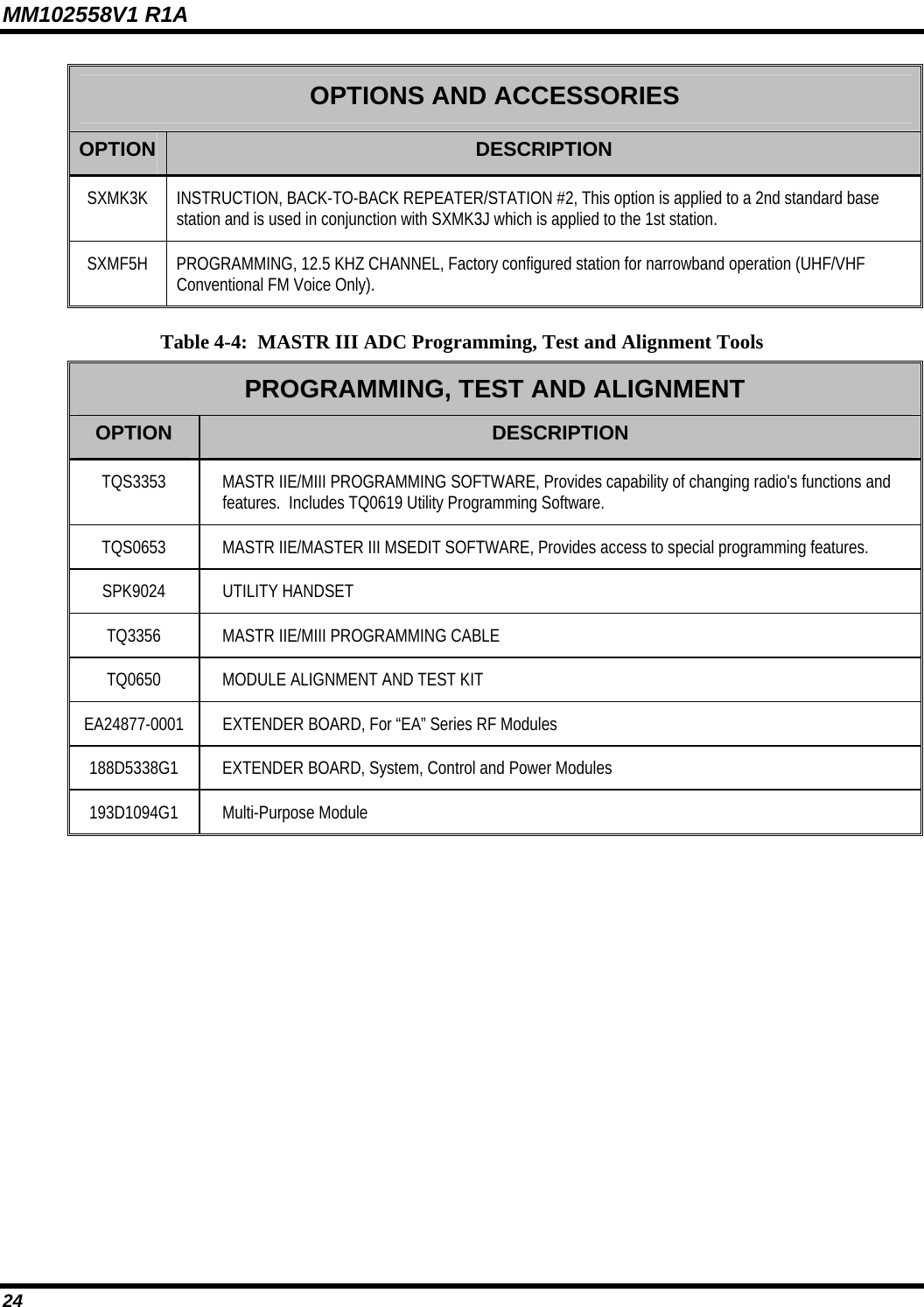
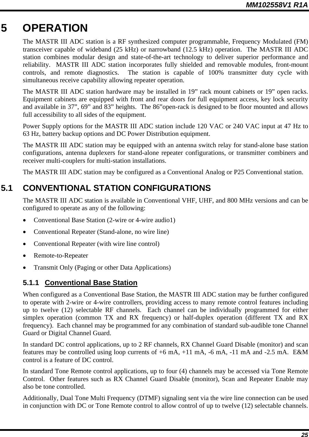
![MM102558V1 R1A 3 SPECIFICATIONS 3.1 CABINET INDOOR CABINET (Floor Mount) OPEN RACK 37-inch 69-inch 83-inch 86-Inch Dimensions [in. (cm)]: Height: 37.0 (94.0) 69.1 (175) 83 (209) 85.5 (217) Width: 21.5 (55.0) 23.1 in. (59) 23-3/16 (59) 21 (53.3) Depth: 18.25 (46.0) 21.0 in. (53.3) 21.0 (53.3) 21 (53.3) Weight (with max. number of channels) Continuous Duty: 121 lbs (55 kg) 576 lbs (261 kg) 693 lbs (314 kg) Packed, Domestic Shipping: 136 lbs (62 kg) 606 lbs (275 kg) 729 lbs (331 kg) Rack Units (RU) (1 RU = 1.75 in.) Cabinet capacity 17 RU 33 RU 41 RU 46 RU Maximum Radio Units: (using 1-RU power supplies) 2 4 5 5 3.2 SOURCE POWER DRAIN VHF UHF 800 TX Frequency Range (MHz) 136-174 380-512 851-870 RX Frequency Range (MHz) 136-174 370-512 806-825 AC Input Power 5A @ 120 VAC or 3A @ 230 VAC DC Input Power (A) VDC Tx 13.8 2 2 2 Rx only 13.8 2 2 2 Tx (full/half power) 26.4 12/8 12/8 12/8 Rx only 26.4 0.5 0.5 0.5 13](https://usermanual.wiki/Raytheon-IDS/M3-UHF-450.Users-Manual-3/User-Guide-1612504-Page-13.png)