Raytheon Raytheon Systems AAGSM191250M Single Channel Amplifier/Antenna User Manual EXHIBIT 7 OPERATION INSTRUCTIONS
Raytheon Company dba Raytheon Systems Co. Single Channel Amplifier/Antenna EXHIBIT 7 OPERATION INSTRUCTIONS
EXHIBIT 7 OPERATION INSTRUCTIONS
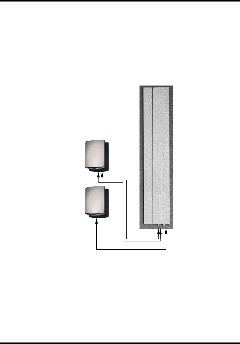
Exhibit 7 Active Antenna FCC Type Acceptance 7/10/01
FCC ID NMFAAGSM191250M 1
Exhibit 7 Operation Instructions
The Active Antenna Unit (AAU) is an integral part of the Maxite system, which also includes a
Ericsson 2302 Radio Base Station (RBS) and an Ericsson Power Battery Cabinet (PBC). A formal
user’s manual for the complete system will be made available through Ericsson.
The AAU portion requires only three connections, a –48 VDC/fault cable connecting it to the
PBC, and the two RF feeder lines connecting it to the RBS. Once the unit has been configured as
shown in Figure 7-1, the system must be calibrated to set its maximum power level as follows:
Figure 7-1 Active Antenna / Radio Base Station / Interface Control Unit
RF
Radio
Base
Statio
n
DC/Alarms
Power
Battery
Cabinet
(PBC)
Active
Antenna
Unit
(AAU)

Exhibit 7 Active Antenna FCC Type Acceptance 7/10/01
FCC ID NMFAAGSM191250M 2
1. After applying power, the installer commands the the Active Antenna Unit, via the PBC control
panel, to reset it’s internal attenuator values to maximum and disable the internal power amplifiers.
This prevents unintentional radiation during the calibration process.
2. The switch operator configures the RBS to transmit one carrier for each AAU transmit function,
with maximum available output power.
3. The installer issues a “set attenuators” command through the PBC. The AAU is then
automatically programmed to step the internal attenuator value down until the pre-determined
drive level is reached, corresponding to the maximum allowable EIRP.
4. A.) If calibration is sucessful, the attenuator settings are stored in non-volatile memory (to protect
the setting in the event of a power failure) and the AAU notifies the PBC that calibration is
complete, and displays the insertion loss of each feeder.
B.) If the AAU is unable to adjust the drive signal to an acceptable level, a fault code is displayed,
and the attenuators are returned to their maximum value.
5. The switch operator turns the RBS output power off.
6. The Active Antenna Unit is commanded to re-enable the power amplifiers.
7. The switch operator can now configure the RBS to the proper frequency and power setting.
NOTE: In general, no GSM radio base staion should be operated at maximum
power in either the first or last channel in any of the allocated PCS bands.
Transmitting a GSM standard modulated signal at full power in either of these
channels will result in a violation of FCC regulations on spurious, out-of-band
emissions (Ref 47 CFR 24.238). For further details, refer to the Ericsson User’s
Guide for the associated radio base station.