Rca Home Theater Av Surround Receiver Rt2250 Users Manual Owner's RT2280 500 Watt System
RT2250R to the manual 1caeec9f-68d3-4916-9e08-c0b7becdafa0
2015-01-23
: Rca Rca-Home-Theater-Av-Surround-Receiver-Rt2250-Users-Manual-274150 rca-home-theater-av-surround-receiver-rt2250-users-manual-274150 rca pdf
Open the PDF directly: View PDF ![]() .
.
Page Count: 31
HOME THEATER AV SURROUND RECEIVER RT2280
6 CH.IN
VCR-2 / VIDEO CAM INPUT
High Current Discrete Amplifier
N
FUNCTION
usermanual
RT2280/RT2250/RT2250R
FCC Information
This device complies with Part 15 of the FCC Rules.
Operation is subject to the following two condi-
tions: (1) This device may not cause harmful
interference, and (2) this device must accept any
interference received, including interference that
may cause undesired operation.
In accordance with FCC requirements, changes or
modifications not expressly approved by Thomson
multimedia Inc. could void the user’s authority to
operate this product.
This device generates and uses radio frequency (RF)
energy, and if not installed and used properly, this
equipment may cause interference to radio and
television reception.
If this equipment does cause interference to radio
or television reception (which you can determine by
unplugging the unit), try to correct the interference
by one or more of the following measures:
• Re-orient the receiving antenna (that is, the
antenna for the radio or television that is
"receiving" the interference).
• Move the unit away from the equipment that is
receiving interference.
• Plug the unit into a different wall outlet so that
the unit and the equipment receiving interference
are on different branch circuits.
If these measures do not eliminate the interference,
please consult your dealer or an experienced
radio/television technician for additional
suggestions. Also, the Federal Communications
Commission has prepared a helpful booklet, "How
To Identify and Resolve Radio TV Interference
Problems." This booklet is available from the U.S.
Government Printing Office, Washington, DC 20402.
Please specify stock number 004-000-00345-4 when
ordering copies.
This product complies with DHHS Rules 21 CFR
Subchapter J. Applicable at the date of
manufacture.
For Your Safety
The AC power plug is polarized
(one blade is wider than the
other) and only fits into AC
power outlets one way. If the
plug won’t go into the outlet
completely, turn the plug over
and try to insert it the other
way. If it still won’t fit, contact
a qualified electrician to change the outlet, or use a
different one. Do not attempt to bypass this safety
feature.
CAUTION: TO PREVENT ELECTRIC SHOCK,
MATCH WIDE BLADE OF PLUG TO WIDE SLOT,
FULLY INSERT.
For Your Records
In the event that service should be required, you
may need both the model number and the serial
number. In the space below, record the date and
place of purchase, and the serial number:
Model No.
Remote Control No. CRK76
Date of Purchase
Place of Purchase
Serial No.
Service Information
This product should be serviced only by those spe-
cially trained in appropriate servicing techniques.
For instructions on how to obtain service, refer to
the warranty included in this Guide
WARNING: TO PREVENT FIRE
OR ELECTRICAL SHOCK HAZARD,
DO NOT EXPOSE THIS PRODUCT
TO RAIN OR MOISTURE. SEE MARKING ON BOTTOM / BACK OF PRODUCT
CAUTION
RISK OF ELECTRIC SHOCK
DO NOT OPEN
THE EXCLAMATION
POINT WITHIN THE
TRIANGLE IS A
WARNING SIGN
ALERTING YOU OF
IMPORTANT
INSTRUCTIONS
ACCOMPANYING
THE PRODUCT.
THE LIGHTNING
FLASH AND ARROW-
HEAD WITHIN THE
TRIANGLE IS A
WARNING SIGN
ALERTING YOU OF
"DANGEROUS
VOLTAGE" INSIDE
THE PRODUCT.
CAUTION: TO REDUCE THE
RISK OF ELECTRIC SHOCK,
DO NOT REMOVE COVER
(OR BACK). NO USER-
SERVICEABLE PARTS IN-
SIDE. REFER SERVICING
TO QUALIFIED SERVICE
PERSONNEL.

1
Table of Content
FCC Information
Getting Started
Unpacking the Receiver . . . . . . . . . . . . .2
Unpacking the Speakers (RT2280 Only) . .3
Inserting Batteries into Remote Control .3
Set Up and Maintenance of the
Receiver . . . . . . . . . . . . . . . . . . . . . . . . . .3
Protect your Components from
Overheating . . . . . . . . . . . . . . . . . . . . . . .3
Connecting to Audio-Visual
Components . . . . . . . . . . . . . . . . . . . . . .4
Digital Connection . . . . . . . . . . . . . . . . .5
Connecting Antennas . . . . . . . . . . . . . . .5
Connecting the Speakers . . . . . . . . . . . . .6
Connecting the Subwoofer . . . . . . . . . . .6
Positioning your Speaker . . . . . . . . . . . . .7
Front Speaker Placement . . . . . . . . . . . . .7
Surround Placement . . . . . . . . . . . . . . . .8
Advanced Surround Setting . . . . . . . . . .8
Test Tone / Channel Balance . . . . . . . . . .9
Connecting for Power . . . . . . . . . . . . . . .9
Using Headphones . . . . . . . . . . . . . . . . . .9
Factory Setting . . . . . . . . . . . . . . . . . . . . .9
Operating your Receiver
Receiver Controls . . . . . . . . . . . . . . . . . .10
Your Remote Control . . . . . . . . . . . . . . .11
Display . . . . . . . . . . . . . . . . . . . . . . . . . .12
Switching On/Off . . . . . . . . . . . . . . . . . .13
Selection of Audio/Video Source . . . . . .13
Using the Remote to Control Additional
Components . . . . . . . . . . . . . . . . . . . . . .14
Using the receiver to play a Source . . . .15
Advanced Sound Control
Sound Enhancement Systems . . . . . . . .19
Fine Setting of Components . . . . . . . . .20
Fine Setting of the Speakers . . . . . . . . .21
Advanced Setting . . . . . . . . . . . . . . . . .21
Care and Maintenance
Troubleshooting Tips . . . . . . . . . . . . . . .23
Receiver/Tuner Operation . . . . . . . . . .23
Remote Control Operation . . . . . . . . .23
General . . . . . . . . . . . . . . . . . . . . . . . .23
Cleaning the Exterior . . . . . . . . . . . . .23
Equipment Specifications . . . . . . . . . .23
Remote Codes
Cable Codes . . . . . . . . . . . . . . . . . . . . . .24
VCR Codes . . . . . . . . . . . . . . . . . . . . . . .24
TV Codes . . . . . . . . . . . . . . . . . . . . . . . .25
Satellite Receivers . . . . . . . . . . . . . . . . .26
Audio (RCA only) . . . . . . . . . . . . . . . . . .26
Laser disc Players . . . . . . . . . . . . . . . . . .26
Limited Warranty (US) . . . . . . . . .27
Limited Warranty (Canada) . . . . .28
EN
Getting Started
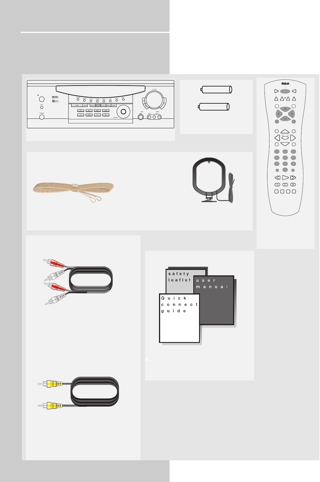
Unpacking the Receiver
You should receive the following items:
2
HOME THEATER AV SURROUND RECEIVER RT2280
6 CH.IN
VCR-2 / VIDEO CAM INPUT
High Current Discrete Amplifier
STANDBY/ON
FUNCTION
+ -
+ -
One receiver unit
One pair of “AA”
batteries
One external FM Dipole
antenna One external AM loop
antenna
one audio cable (two wires) with red
and white RCA connectors;
one video cable (single wire) with
yellow RCA connectors;
STOP PAUSE
TV
ON OFF
VCR1
VCR2
DVD•6 CH
LEVELAUDIO
RECORD
SURRDIGITAL
PLAY FORWARDREVERSE
MUTE
C
H
+
C
H
-
V
O
L
V
O
L
TAPECD
MENU CLEAR
123
456
789
0
SAT•CABLE
universal
AM•FM
INFO•RDS
INPUT•SEEK ANT•FMS
G
O
B
A
C
K
•
D
I
S
K
G
U
I
D
E
•
R
D
M
•
P
T
Y
OK
• one instruction book;
• one safety leaflet;
• one Quick Connection Guide
One RCA Universal
Remote Control
(CRK76)
Getting Started
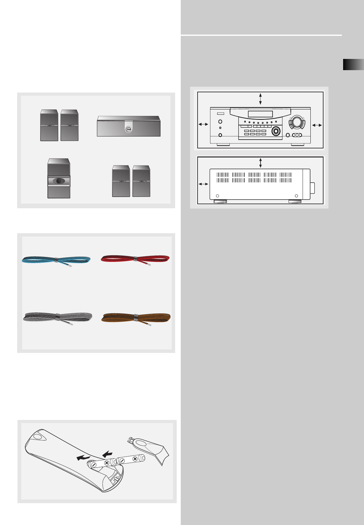
Unpacking The Speakers (RT2280/RT2250 Only)
• one set of speakers including 2 left and right front
speakers, 1 centre speaker, 1 subwoofer and 2 left
and right rear speakers.
• 6 speaker cables including:
Inserting Batteries into Remote Control
Insert two AA(R6) batteries according to the + and -
signs on the battery compartment. To use the remote
control, point it directly at your receiver.
Set up and Maintenance of the Receiver
• Provide spaces for sufficient ventilation as
indicated:
• Do not connect to the AC power cords until all
connections are completed.
• Do not use your set immediately after transferring
it from a cold place to a warm place: there is risk of
condensation.
• Do not expose your set to water and excessively
high temperatures.
• After having disconnected your set, clean the case
with a soft cloth, or with a slightly damp leather
chamois. Never use strong solvents.
Protect your Components from
Overheating
• Do not block ventilation holes in any component.
Arrange the components so that air can circulate
freely.
• Do not stack components directly on top of each
other.
• Allow adequate ventilation when placing your
components in a stand.
• Place an amplifier near the top shelf of the stand
so heated air rising from it will not affect other com-
ponents. If you have a satellite receiver, you should
place it on the top shelf.
EN
3
10 cm/4"
10 cm/
4" 10 cm/
4"
10 cm/4"
5 cm/
2"
FRONT SPEAKERS CENTER SPEAKERS
SUB WOOFER REAR SPEAKERS
(SURROUND SOUND)
2 X grey/black cable
for rear speakers 1 X brown/black
cable for subwoofer
1 X blue/black cable
for centre speaker 2 X red/black cable
for front speakers
Getting Started
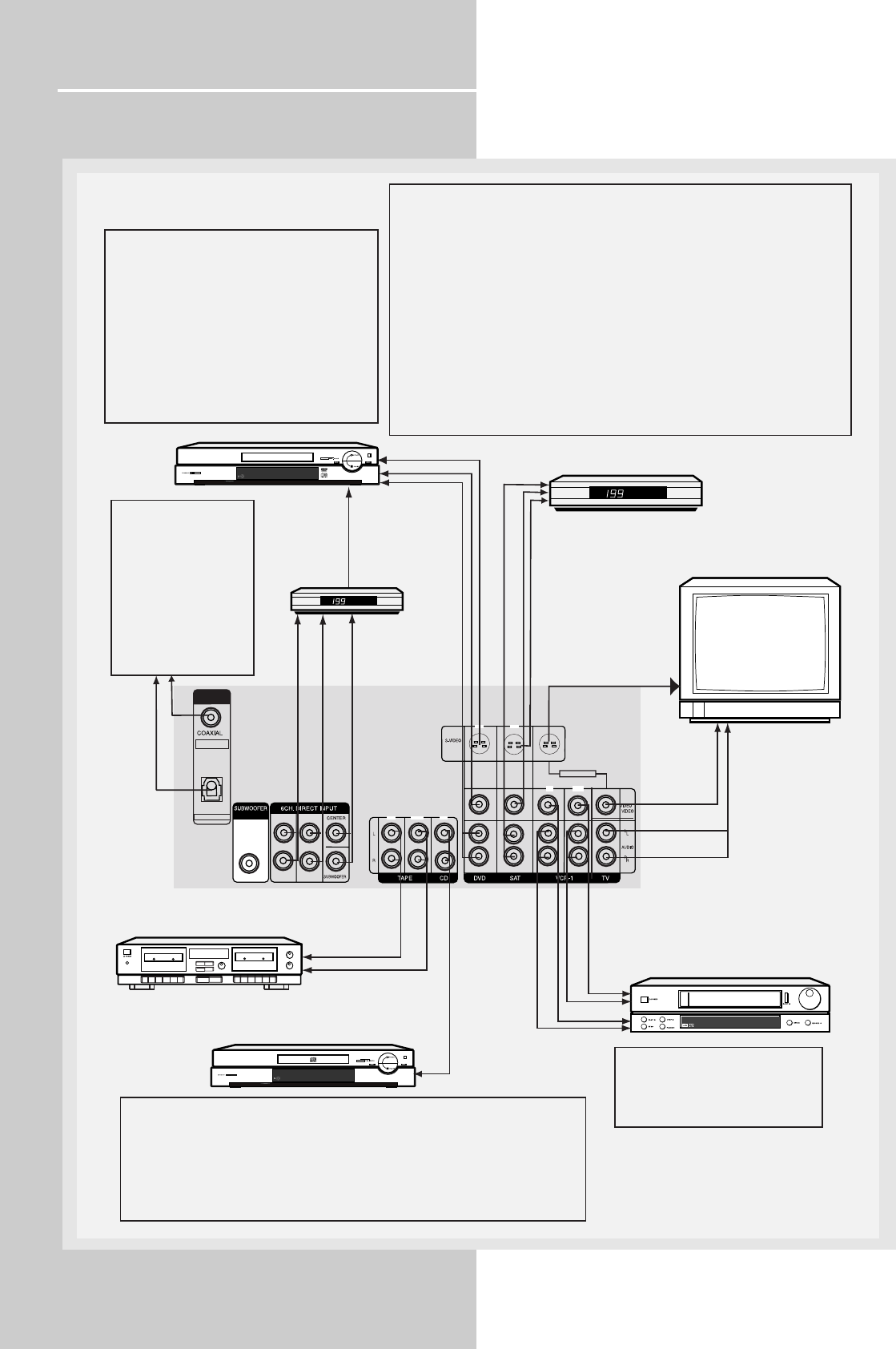
Connecting to Audio-Visual Components
4
PRE OUT
FRONT L REAR L
FRONT R REAR R
IN IN
IN OUT IN
MONITOR OUT
IN OUT
DIGITAL INPUT
DVD/CD/SAT
DVD/CD/SAT/TV
OPTICAL
TV
VCR
CD Player
Tape Deck
SAT
Multi-Channel
Decoder
e.g. DTS
to LINE OUT
(Tape Deck)
to LINE IN ( Tape Deck )
to AUDIO OUT (CD)
to VIDEO OUT (SAT)
to AUDIO OUT (SAT)
to S-VIDEO OUT (SAT)
to S-VIDEO OUT (DVD)
to AUDIO OUT(DVD)
to VIDEO OUT (DVD)
to AUDIO OUT (TV)
to VIDEO IN (TV)
to S-VIDEO IN (TV)
to AUDIO OUT (VCR)
to VIDEO OUT (VCR)
to VIDEO IN (VCR)
to AUDIO IN (VCR)
to AUDIO OUT
to AUDIO OUT (DVD)
UNIT
BACK PANEL
DIGITAL CONNECTION
If you have a SAT receiver DVD player or CD player with a digital output, you can make
use of an optical digital connecting cord (not supplied) or coaxial digital connecting
cord (not supplied) to carry the audio portion of the signal and enjoy Dolby Digital
sound quality. One optical or coaxial cable is needed for each SAT receiver, DVD
player or CD player. When optical or coaxial cable is used, the analog audio cables are
still needed if recording through a tape or VCR is desired. This receiver provides one
optical and one coaxial digital input for the connection of your components. Please
connect your components (e.g. DVD, SAT or CD) to the appropriate digital inputs and
press FUNCTION and then rotate MULTIJOG to match your connection.
Note: Optical and coax cables carry only the audio portion of the signal. A video
connection must also be established for a SAT receiver and DVD player. S-video
provides the best connection for the video portion of the signal. Composite video
(yellow RCA connector) can also be used. It is
important that the same type of cable (S-video or composite) that is connected from the
Home Theater to the TV is used to connect the SAT receiver or DVD player to the
Home Theater.
FRONT TERMINAL
Remark: If you have a video
camera, video game machine, or an
extra VCR, connect it to VCR 2 jack
at the front of the receiver
DIGITAL INPUT
Connect components
capable of outputing
Dolby Digital (e.g. DVD
or SAT) or standard
PCM (CD) format digital
signals. Read section on
"Input Signal Setting"
under "Advanced Sound
Control" carefully to
adjust the matching
input settings.
If your CD player is equipped with digital optical jacks, use of optical cable is preferred.
What you need is just one more optical digital connecting cord(not supplied). Plug it in
the digital input jack of the receiver and select OPTICAL on the receiver setting (see
details on pg 20 chapter "Input Signal Setting"). You can enjoy better sound quality
brought to you by the optical cable. When optical cable is used, analog cables are still
needed for recording to tape output.
Note: This receiver has one digital optical jack only. Be sure that such connection does
not prevent optical cable connection of other components (e.g. DVD & SAT)
S-VIDEO
If your video component has a S-Video jack
included, you can make use of it to enjoy
enhanced video quality by connecting it to the
relevant S-Video jack at the rear side of the
receiver. One video cable is needed for each
component. When S-Video cable is used,
composite video (yellow RCA connector) cable
must also be connected for VCR recording.
Note: Before plugging in the optical cable or
S-Video cable, make sure to match the shape of
the plug and jack, otherwise, you will not be able
to plug in completely.
DVD
(Decoder)

Getting Started
EN
5
MODEL NO.: RT2280
300
THOMSON MULTIMEDIA INC.
8
FRONT SPEAKERS (8‰)
SUBWOOFER (8‰)
CENTER SPEAKER (8‰)
PRE OUT
FRONT L REAR L
FRONT R REAR R
RT2280
Rev
.
0
2001/01/12
IN IN
IN OUT IN
MONITOR OUT
DIGITAL INPUT
DVD/CD/SAT
DVD/CD/SAT/TV
OPTICAL
IN OUT
ANTENNA
AM
LOOP
FM
75‰
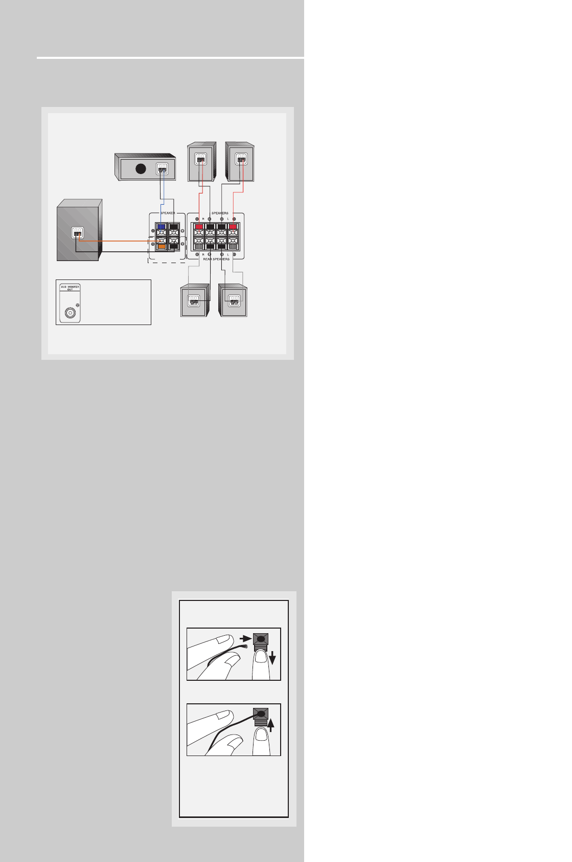
Antenna and Speaker
Wire Connection
Push Speaker terminal tab
down to insert wire.
Release tab to lock wire in
the terminal.
NOTE: Make sure the insulation
is completely removed from the
ends of the Antenna and
speaker wires at all connection
points.
Digital Connections
Read instructions carefully when connecting compo-
nents to the receiver.
Digital In Jacks can accept Dolby Digital (AC-3), or
PCM signals when compatible components are con-
nected.
Connecting the Antennas
The AM and FM antennas connect to the AM and FM
terminals on the system’s back panel.
They must be hooked up in order to receive clear
reception.
AM Loop Antenna and FM Indoor Antenna
1. Uncoil the Antenna wire and located the base end
2. Press down on the Antenna tab to open the termi-
nal
AM Loop Antenna
MODEL NO.: RT2280
300
THOMSON MULTIMEDIA INC.
8
FRONT SPEAKERS (8‰)
SUBWOOFER (8‰)
CENTER SPEAKER (8‰)
PRE OUT
FRONT L REAR L
FRONT R REAR R
ANTENNA
IN OUT IN
MONITOR OUT
DIGITAL INPUT
IN OUT
ININ
AM
LOOP
FM
75‰
DVD/CD/SAT
DVD/CD/SAT/TV
OPTICAL
DIGITAL INPUT
DVD/CD/SAT
DVD/CD/SAT/TV
OPTICAL
SAT / DVD / CD Player / TV
COAXIAL DIGITAL IN (AUDIO)
Connect to coaxial digital output of
DVD, CD, SAT or other compatible
devices.
OPTICAL DIGITAL IN (AUDIO)
Optical Fiber Cable
Connect to optical digital output of
DVD, CD, SAT or other compatible
devices.
DVD / CD / SAT
HINT
• For FM reception, extend antenna to its full
length and arrange the Antenna as a T Shape
• For AM reception, rotate the antenna hori-
zontally to get better reception.
ANTENNA
AM
LOOP
FM
75Ω
Getting Started
Connecting the Speakers
Speakers
There are 6 speakers equipped with the unit (2 front,
1 center, 2 rear, 1 subwoofer). In order to enjoy good
surround effects all six speakers need to be
connected to the receiver
At least two front speakers (left and right) are
required. For better sound quality, Center speaker,
rear speakers and Subwoofer should also be
connected. Adding center and rear speakers will
enhance surround effects. Adding a Subwoofer will
increase bass response.
If you want to enjoy full range of sound effects, with
small speakers, it is a must to use the subwoofer with
the speakers to maintain adequate bass signal.
Speaker cords
1 for each speaker, is
needed for connection.
Twist the stripped ends of
speaker cord about 2/3
inch (15 mm). Press down
on the tab to open the ter-
minal and insert the wire.
Snap the tab closed.
To ease speaker connections, the speaker cords and
the terminals are color-coded.
• Red/Black (Front Speakers),
• Blue/Black (Center Speaker)
• Grey/Black (Rear Speakers).
• Brown/Black (Subwoofer)
Connect the L, R speaker (with red/black terminal) on
the back of the speakers to the corresponding color
on the receiver. Do the same for center (with
blue/black terminal), rear speaker (with grey/black
terminal) and the subwoofer (with brown/black ter-
minal).
Speaker Polarity
When connecting the speakers, make sure the polari-
ties (“+” speaker wire to “+” on the receiver) of
speaker wires and terminals are matched. If the cords
are reversed, the sound will be distorted and will lack
bass (“out of phase” effect).
Connecting the Subwoofer
For RT2280/RT2250, connect the subwoofer with the
speaker cord (brown/ black) provided. For RT2250R,
or if you want to connect your own powered sub-
woofer, a mono aural audio cord (not supplied) is
needed (RCA terminal).
This receiver offers a high flexibility for user to use a
large variety of speakers and subwoofers. For more
information please refer to section “Fine Setting of
the Speakers” in “Advanced Sound Control” on page
21.
6
SUB WOOFER
SPEAKER
RIGHT
+-
LEFT
+-
LEFT
+-
RIGHT
+-
CENTER
SPEAKER
FRONT SPEAKERS
REAR SPEAKERS (SURROUND SOUND)
+-
SUB WOOFER
+-
FRONT
This part not
available for RT2280R
CENTER
Use this jack on the left
back panel to connect
another powered
subwoofer other than
the one supplied.
Antenna and Speaker
Wire Connection
Push Speaker terminal tab
down to insert wire.
Release tab to lock wire in
the terminal.
NOTE: Make sure the insulation
is completely removed from the
ends of the Antenna and
speaker wires at all connection
points.
Getting Started
Positioning your speaker
1 Left, Right (Front Speakers)
They carry primarily music and sound effects
2 Center
In surround mode, the center speaker carries much of
the dialogue as well as music and effects. It should be
set between the left and right speakers.
3 Surround (Rear Speakers)
Their overall sound balance should be as close as pos-
sible to the front speakers. Proper placement is vital
to establish an evenly distributed sound field.
Subwoofer
A subwoofer is designed to reproduce powerful low
bass effects (explosions, the rumble of spaceships,
etc.) which dramatically heightens involvement with
the action on the screen. It is therefore recommend-
ed to connect subwoofers when small speakers are
used.
Magnetic shielding
Speakers placed less than two feet from the TV set
must be magnetically shielded in order to prevent
picture distortion. Front and center speakers provid-
ed with RT2280/RT2250 are magnetically shielded to
protect your TV set.
It is not recommended to place the rear speakers
near the TV set.
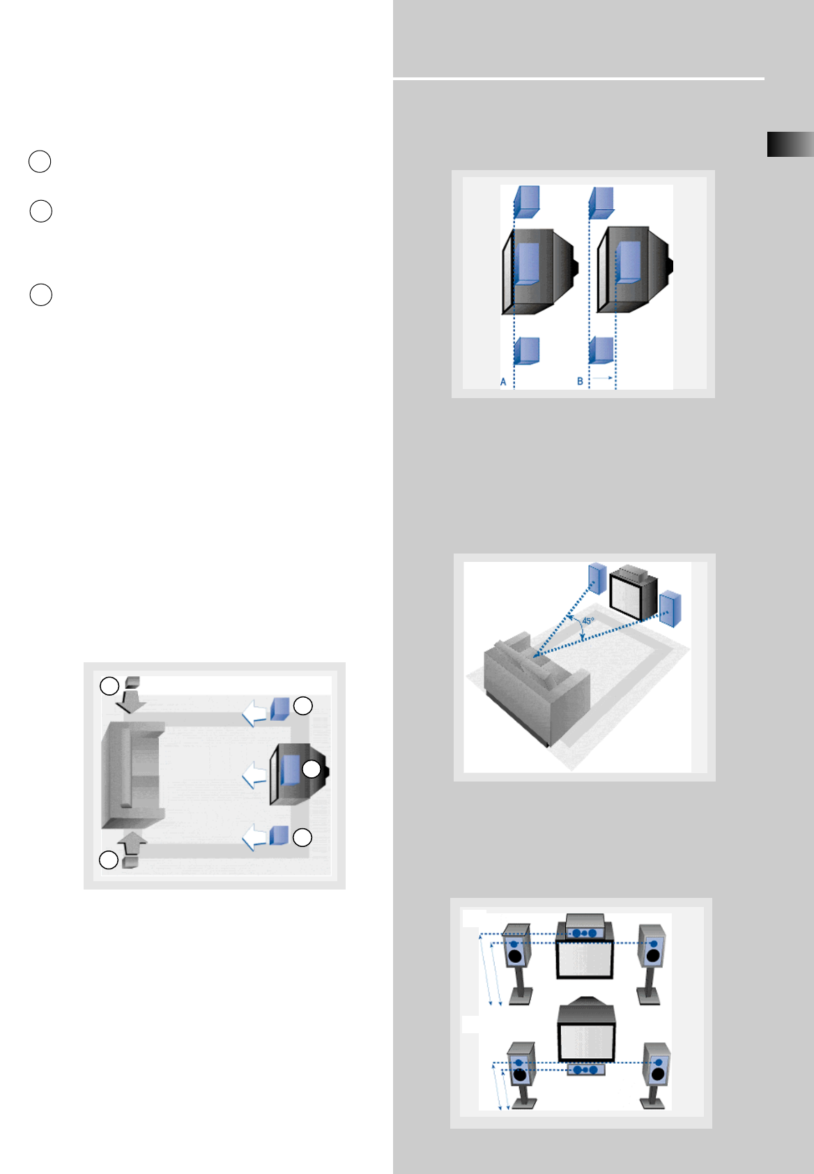
Front Speaker Placement
Even if you can't duplicate this ideal home theater
setup exactly, the suggestions for speaker placement
that follow will help you get good results.
Alignment
Align the center speaker evenly with (A), or slightly
behind (B), the left and right speakers, but not ahead
of them.
Advanced Setting
Angle
Placing the left and right speakers to form a 45-
degree angle with your favorite viewing position will
duplicate the soundtrack mixer's perspective.
Height
The mid- and high-frequency drivers of the three
front speakers should be as close as possible to the
same height. This often requires placing the center
speaker directly atop (A) or beneath (B) the TV set.
EN
7
1
1
2
3
3
A
B
Courtesy Dolby Laboratories
Courtesy Dolby Laboratories
Courtesy Dolby Laboratories
Courtesy Dolby Laboratories

Getting Started
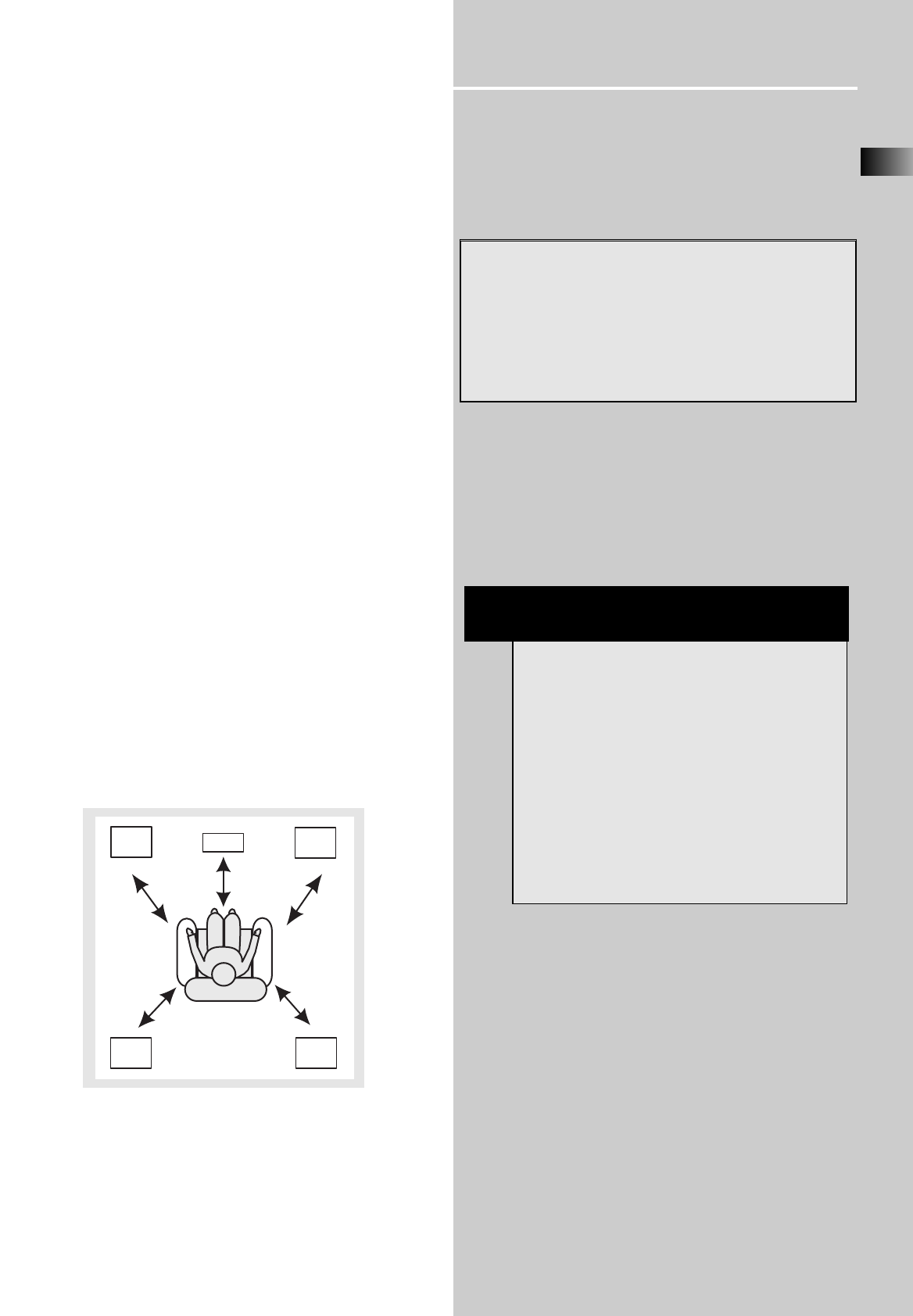
Preferred surround placement
Location
If possible, place surround speakers to either side of
the listening area, not behind it.
Height
If space permits, install surrounds 2-3 feet above
viewers. This helps to minimize localization effects.
Aiming
Aiming surrounds straight across the room, not down
at viewers, helps create a more open, spacious sur-
round sound field.
Advanced Setting
Alternative Surround Placement
Rear wall
If rear wall mounting is the only choice, aim the
speakers at each other (A), towards the front (B) or
even towards the sidewalls (C, D). Experiment with
placement until surround sounds seem to envelop
you, rather than coming from behind you.
No adjacent walls
Surrounds can go on stands facing each other to
approximate the preferred sidewall mounting (A), or
to the sides or rear of the viewing area aimed
upwards. In the latter case, they can go right on the
floor, or preferably, a few feet off the floor such as
on end tables (B).
8
Courtesy Dolby Laboratories
Courtesy Dolby Laboratories
Courtesy Dolby Laboratories
Courtesy Dolby Laboratories
Courtesy Dolby Laboratories
Getting Started
EN
9
Test Tone / Channel balance
Channel balance
Your receiver is equipped with a test signal generator
for balancing the channels. As the signal "travels"
from channel to channel, adjust the level controls
until each channel plays at the same loudness level.
(details see operation of test/setup)
Level adjustment & surround channel level expec-
tation
Even though you adjust the surround channel to be
as loud as the others on the test signal, you'll find
that on actual program material the surround chan-
nel is usually much lower than the front. Don't be
tempted to readjust the surround level; program pro-
ducers use surround mostly for subtle atmosphereics
and ambience, and only rarely for special effects. A
good surround mix doesn't call attention to itself; if
it did, it would soon become distracting.
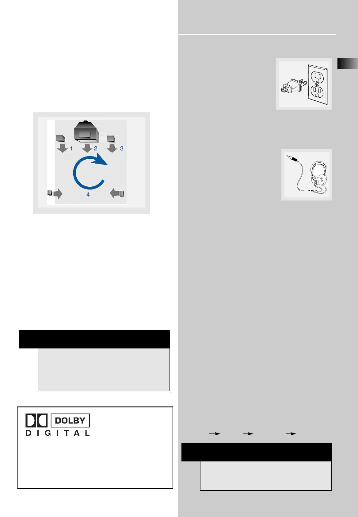
Connecting for Power
Make sure you connect all your
other electronic components and
the
speakers before plugging your
receiver into the outlet. Plug the
power cord in the wall outlet,
matching the wide blade of the
plug with the wide slot in the
outlet. Be sure to insert the plug completely.
Using Headphones
To listen privately through your
audio system, use the PHONES jack
on the receiver. However, make
sure you turn down the volume
before you put on the head-
phones. Increase the volume to the
desired level after headphones are
in place.
Once headphones are connected, “HEADPHONE
DOWNMIX 2 CHANNEL” will scroll on display. This
feature automatically converts multi-channel speaker
outputs to 2 channel stereo for your listening pleas-
ure.
Hearing Comfort & Well-Being
• Do not play your headset at a high volume.
Hearing experts advise against continous extended
play.
• If you experience a ringing in your ears, reduce
volume or discontinue use.
Factory Setting
The RT2280/RT2250 is preset to the following setting
when you first time turn on the power
Function = Tuner
Surround mode = Stereo (Left + Right (small) + sub-
woofer on)
Volume setting = 25 dB
Bass & treble = 0 dB
Restore to Factory Settings
You can always restore all settings back to its original
state. When the receiver is in STANDBY mode, press
accordingly to restore all settings back to factory
default :
STADIUM NIGHT DSP OFF CLUB
NOTE
The system is equipped with Dolby Digital,
and manufactured under License from Dolby
Laboratories.
Dolby Digital
Manufactured under
license from Dolby
Laboratories. “Dolby”,
“Pro Logic” and the double-D symbol are trade-
marks of Dolby Laboratories. Copyright 1992-
1997 Dolby Laboratories, Inc. All Rights Reserved.
NOTE
All preset radio stations and surround sound
setting will be lost after factory setting is
restored.
Courtesy Dolby Laboratories

Operating Your Receiver
HOME THEATER AV SURROUND RECEIVER RT2280
6 CH.IN
VCR-2 / VIDEO CAM INPUT
High Current Discrete Amplifier
STANDBY/ON
FUNCTION
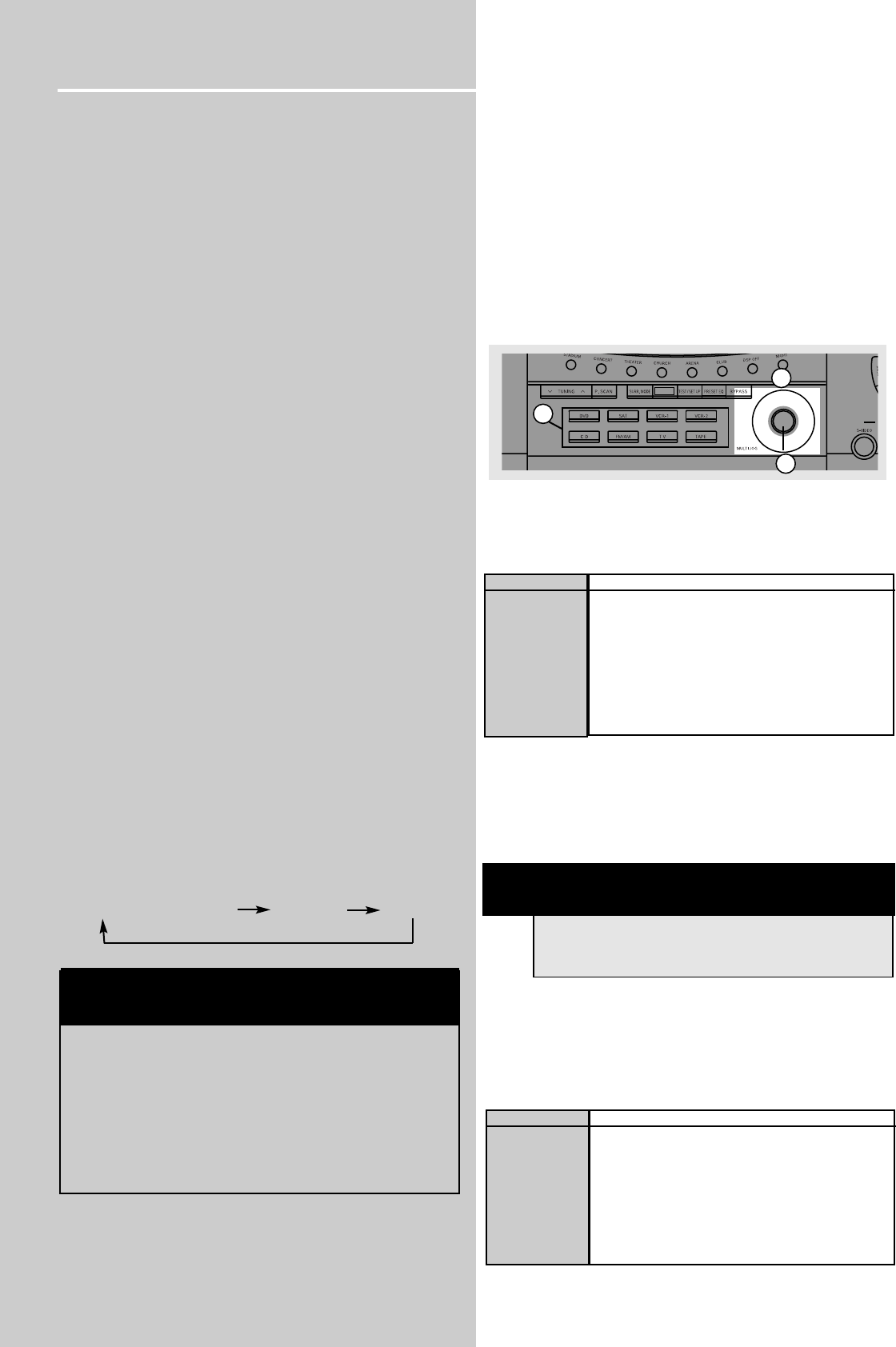
Receiver Controls
1. STANDBY/ON
To turn the unit on/ off. When the system is turned on, the unit
will go to the mode it was in before power off.
2. MUTE
To mute all audio outputs.
3. PHONES
Plug your headphones (not supplied) into it for your private
enjoyment. Speakers will be off when phones are inserted.
4. Source Buttons
To select sound source. For example, CD, SAT etc.
5. Display
To display current status of the receiver.
6. Sound Control
Let you adjust the sound – volume, treble, bass & balance.
• To change the VOLUME, turn the large central
knob.
• To adjust TREBLE or BASS, press relevant button and turn the
knob.
• To change the volume of individual speaker, press LEVEL but-
ton repeatedly to select the speaker, then turn the knob to
adjust the level. ( refer to “The TEST/ SET UP button” on page
21)
7. DSP (Digital Sound Processor) & NIGHT mode
Press corresponding button to select the DSP mode
(STADIUM/ CONCERT/ THEATER/ ARENA/ CHURCH/ CLUB/ OFF)
you want.
Press NIGHT for your enjoyment at night (see page 20).
8. MULTI JOG, FUNCTION
When pressing FUNCTION repeatedly, the display will toggle
among Audio Source (for DVD, SAT & CD), SLEEP mode and
DIM selection.
Please refer to page 20 for “Input Signal Setting”.
• In SLEEP mode, you can set the receiver to turn off after 30,
60, 90 or 120 minutes.
• In DIM selection, you can rotate to set the brightness of the
display. Such setting will be stored.
• Use MULTI JOG for speakers and sub-woofers setup and pre-
set radio stations selection.
9. TUNING
Press for about 2 seconds to activate Automatic Preset function.
Press once to review all preset stations.
10. P. SCAN (Preset Scan)
• Press and hold for about 2 seconds to start the automatic
tuner station preset.
• Press to view preset stations one by one.
11. SURR. MODE
Press repeatedly to select the surround mode you want. ( refer
to “Advanced Sound Control” on page 20.)
12. 6 CH (6 Channels External Input)
Press to select the input connected to an external 6-Channel
decoder. Press again to return to the most recently selected
source mode. (see 6 Channel External Input on page 11).
13. TEST/ SET UP
When pressing it briefly, a short noise (test tone) will be gener-
ated in the speakers one by one so that you can adjust the vol-
ume of individual speaker. When keep pressing for two sec-
onds, it will enter setup mode for speakers and subwoofers.
Rotate the MULTI JOG to choose the options. (refer to “The
TEST/ SET UP button” on page 21.)
14. PRESET EQ
Press repeatedly to select the desirable EQ mode (music style) –
CLASSIC, POP, ROCK, JAZZ, VOCAL or FLAT. Your choice will be
saved automatically.
15. BYPASS
Press to go back to stereo sound (no DSP effect, no sound from
center and surround speakers)
16. VCR2/Video Cam Input
For convenient use of your digital camera, family game
machines, second VCR, etc.
12
34
7 6
8
9
10 11 12 13 14 15
16
5
10
Operating Your Receiver
EN
11
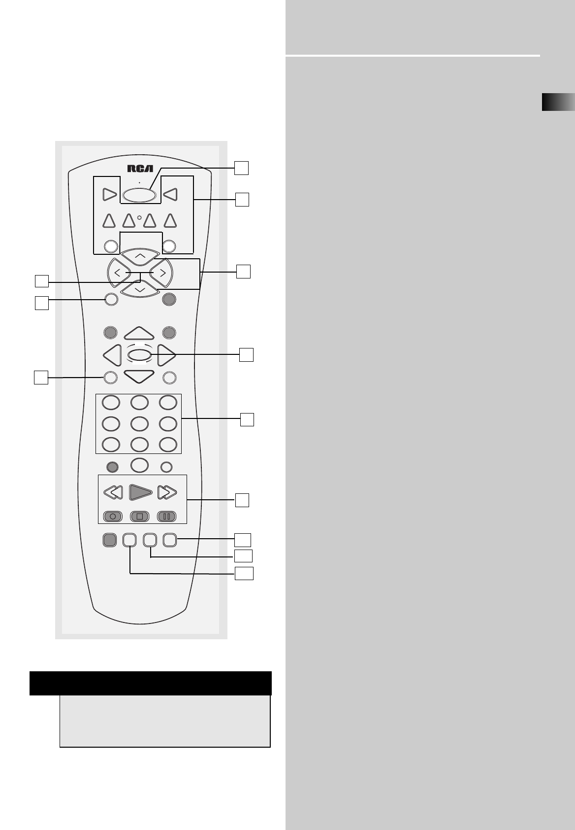
Your Remote Control
Please be sure you have inserted the batteries into the
remote control (see relevant section on page 3.) You can
test it by pressing any button. If it works, the red LED
will light.
1. ON/OFF
To turn on or off the receiver and other auxiliary compo-
nents (see page 14 “Using the Remote to Control
Additional Components”).
2. Source Buttons
To turn on and select various audio/ video sources. You can
also enter the 6 Channels direct input mode by pressing
DVD•6CH.
3. CH+, CH- (Channel Buttons)
To select programmed stations (in TUNER mode).
4. VOL (Volume Buttons)
To adjust the volume.
5. MUTE
To mute all audio outputs.
6. Adjustment Buttons
Press AUDIO button to activate the control, then upon
pressing OK/FUNCTION, the display will toggle among:
• Preset EQ (Stereo only),
• SLEEP Mode
• DIM Mode.
When the display shows the setup you want to change,
press the left and right arrow buttons beside OK button to
make changes, then press OK to finalize your choice.
7. Number Buttons
To access directly a pre-set station or to peripheral devices
(in TUNER mode).
8. MENU (Tuner Mode only)
• Press AM/FM
• Press to store desired frequency in memory. The flashing
word MEMORY in red will appear in display. Input your
desired channel number while the word is still flashing and
the frequency will be stored. (For details, refer to "Storing
and Recalling Stations in Memory" on page 10.)
9. Operation Buttons
In TUNER mode, press AM/FM on the remote.
• Press REVERSE and FORWARD keys to tune down or up
the radio frequency.
• PLAY, RECORD, STOP and PAUSE keys are only for easy
control of external devices that are connected to your
receiver such as CD, TV, DVD, TAPE, etc.. The remote control
currently operates most Thomson, RCA and GE products,
but it can be programmed to operate devices from other
manufacturers (For details, refer to “Using the Remote to
Control Additional Components” on page 14.
10. DIGITAL
Select the way your audio/video components are connected
to the receiver (Analog, Optical, Coaxial or Input/Output).
11. LEVEL
Press to adjust the volume of individual speaker. Press
repeatedly and the display will toggle among different
channels (Left front speaker, Right front speaker, Center
speaker, Left rear speaker, Right rear speaker, and
Subwoofer). Press the left and right arrow buttons beside
OK button for adjustment.
12. SURR (Surround Sound Control)
Press to change the surround sound settings. The display
will toggle among DOLBY DIGITAL, DOLBY PRO LOGIC,
DOLBY 3 STEREO, STEREO and DSP modes.
(For details, refer to section "Advanced Sound Control" on
page 19.)
STOP PAUSE
TV
ON OFF
VCR1
VCR2
DVD•6 CH
LEVELAUDIO
RECORD
SURRDIGITAL
PLAY FORWARDREVERSE
MUTE
C
H
+
C
H
-
V
O
L
V
O
L
TAPECD
MENU CLEAR
123
456
789
0
SAT•CABLE
universal
AM•FM
INFO•RDS
INPUT•SEEK ANT•FMS
G
O
B
A
C
K
•
D
I
S
K
G
U
I
D
E
•
R
D
M
•
P
T
Y
OK
FUNCTION
NOTE
The remote buttons GO BACK•DISK,
GUIDE•RDM•PTY, INFO•RDS, INPUT•SEEK &
AUDIO do not work in tuner mode.
1
4
2
3
5
9
12
11
10
6
7
8

Operating Your Receiver
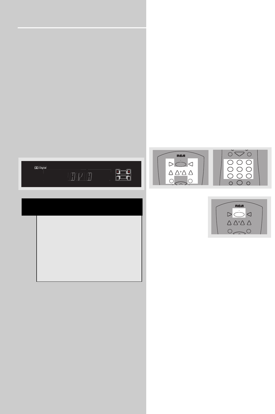
• Audio output is in Dolby Digital mode.
• Audio output is in Dolby ProLogic mode.
• Audio output is in 3 Stereo mode.
• Tuner stereo signal detected.
• Tuner station detected.
• Unit is in DSP (Digital Sound Processing) mode.
• Speaker Icons.
• Unit in Sleep mode.
• Unit in Memory mode.
• Tuner frequency unit.
DSP
ST
TUNED
SLEEP
MEMORY
KHz
MHz
12
Display

Operating Your Receiver
EN
13
Switching on /off
• To switch on the receiver, press STANDBY/ON but-
ton (1) once. Alternatively, you can press any of the
source buttons to power on the receiver.
• Standby: when the receiver is on, press the
STANDBY/ON button once to activate the standby
mode.
• To switch off the unit completely, unplug the
power cord from the socket
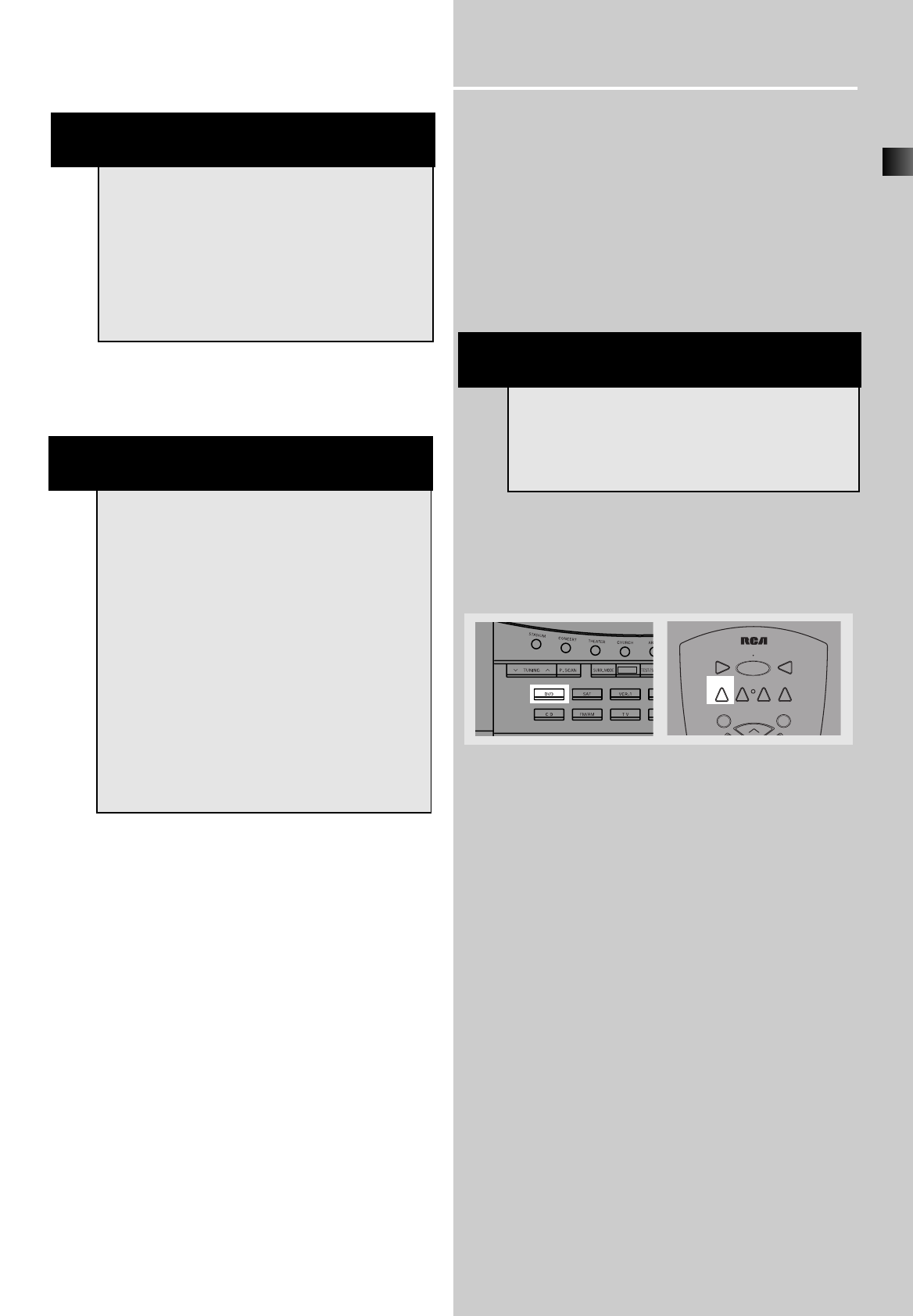
Selection of Audio/Video source
When one of the source button is pressed, the audio
and video input corresponding to the name will be
activated.
The receiver acts as a switching device between all
the sources that are plugged into to it.
Example 1:
If you connect a DVD player to the DVD input
(audio + video) on the receiver and press the DVD
button, you will be able to have the sound and
image transmitted by the DVD.
Example 2:
Based on the example 1, the DVD is playing , if a
VCR is connected to the VCR 1 input (audio +
video) of the receiver and the VCR1 button is
pressed, image and sound from the VCR source will
replace the DVD.
NOTE
Your receiver has a back up memory to keep
your settings like preset radio station for
about 2 weeks in case electricity cut occurs. If
the receiver is unplugged for more than 2
weeks, all the settings will be lost and re-set-
ting will be necessary.
STANDBY/ON
THEATER AV SURROUND RECEIVER RT2280
6 CH.IN
TV
ON OFF
VCR1
VCR2
DVD•6 CH
C
H
+
TAPECD
SAT•CABLE
AM•FM
TV
ON OFF
VCR1
VCR2
DVD•6 CH
L
V
T
SAT•CABLE
AM•FM
C
H
+
APECD
THEATER AV SURROUND RECEIVER RT2280
6 CH.IN
HOME THEATER AV SURROUND RECEIVER RT2280
6 CH.IN
t
e Amplifier
TV
ON OFF
VCR1
VCR2
DVD•6 CH
T
SAT•CABLE
AM•FM
C
H
+
APECD
6 CH.IN
E
R AV SURROUND RECEIVER RT2280
TV
ON OFF
VCR1
VCR2
DVD•6 CH
T
SAT•CABLE
AM•FM
C
H
+
APECD
TV
ON OFF
VCR1
VCR2
DVD•6 CH
L
V
T
SAT•CABLE
AM•FM
C
H
+
APECD
Operating your Receiver
You can connect up to 7 audio/video sources to this
amplifier:
Source button Corresponding connector
(receiver front panel) (receiver back panel)
- DVD DVD IN (audio / video)
- SAT SAT IN (audio / video)
- VCR-1 VCR-1 IN (audio / video)
- VCR-2 VCR 2 IN (audio / video)
- CD CD IN (audio only)
- TV TV IN (audio only)
- TAPE TAPE IN (audio only)
- FM/AM built-in
When a source is selected, the source name will be
shown on the display.
Example: Press DVD to select DVD as the source to
the amplifier.
Using the Remote to Control Additional
Components
You can set your remote to control other components
(like CD, TV, DVD, TAPE, etc.). What you need is to
encode them in advance (not necessary for recent
RCA & Proscan models).
1. Turn on the component to be programmed.
2. Look up the brand and corresponding code num-
ber in the code list from page 24 to 26.
3. Press and hold the corresponding Source Button
(like VCR1, VCR2, TV, DVD) on the remote while
entering the code from the code list using the
Number Buttons.
4. Release the compo-
nent button, then press
ON•OFF to see if the
component will be
turned off.
5. If this does not work, repeat steps 3 and 4 by try-
ing to use the next code (if available) listed for the
brand of your component until the component
responds to the remote command.
NOTE
1. Your receiver has a built in tuner. Just con-
nect the appropriate antenna on the back of
the receiver and you will be able to listen to
radio stations. (See details in Tuner section)
2. Other sources can be connected to the
above standard source. Example: you can con-
nect a LD into the DVD inputs.
3. Refer to the "Connecting To Audio-Visual
Components" section for details on connec-
tion.
TV
ON OFF
VCR1
VCR2
DVD•6 CH
T
SAT•CABLE
AM•FM
C
H
+
APECD
MENU CLEAR
123
456
789
0
INPUT•SEEK ANT•FMS
FUNCTION
TV
ON OFF
VCR1
VCR2
DVD•6 CH
C
H
+
TAPECD
SAT•CABLE
AM•FM
14
Operating your Receiver
EN
15
Using the receiver to play a source
After having properly connected a source (DVD, CD,
VCR) to the receiver, you can partly control them
through the receiver.
Playing a DVD with the receiver
1. Connect a DVD player to the receiver (see connect-
ing your receiver for details)
2. Press STANDBY/ON to switch on the receiver
3. Select the DVD source by pressing the DVD source
button
4. Switch ON the DVD player and start playback
5. Switch ON your TV
6. Select the appropriate A/V channel on the TV
(refer to your TV manual for details) until the image
from the DVD player is displayed
7. Set the sound Mode if needed (see "Advanced
sound control" for details)
Example 1:
To play 5.1 Dolby Digital surround sound
Press SURR. MODE button until "Dolby Digital"
appears on the Display and all of the speakers’
icons light up.
Example 2:
DVD: You may also need to select the Dolby Digital
5.1 on the DVD disc menu to have the digital sur-
round enabled providing that the disc is encoded
with Dolby Digital 5.1 (please refer to the DVD
player and DVD disc instruction)
NOTE
Once your remote is encoded, you can press
ON/OFF on the remote once to turn off the
component and then followed by the second
time quickly to turn off the receiver (i.e. this
unit). If you only want the receiver to be
turned off, select FM/ AM while the unit is ON
before pressing ON/OFF.
HINT
This remote may not operate all models of
the brands shown.
If batteries are removed from the battery
compartment of the remote control, all mem-
ory will be lost. You need to re-enter all
previously programmed codes again.
The buttons on the remote may not work
correspondingly with those on other brand
components. Experiment with the remote and
your components to see which buttons work.
If only a few functions operate, check to see if
another code set will work with more but-
tons.
NOTE
To play Dolby Digital sound, the source must be
connected to the receiver via the optical or
coaxial terminal (see "Digital Connection” on
page 5 for details)
HOME THEATER AV SURROUND RECEIVER RT2280
6 CH.IN
e
Amplifier
TV
ON OFF
VCR1
VCR2
DVD•6 CH
T
SAT•CABLE
AM•FM
C
H
+
APECD

Operating your Receiver
Example 3:
LD: You may need to select a different Audio
Channel on your LD (refer to your LD player manu-
al)
8. Adjust volume knob accordingly
Operating the Radio
The receiver has a built-in tuner that allows for
AM/FM radio function.
Manual tuning
1. Connect the FM and AM antenna accordingly (see
"Connecting the Antenna" on page 5 section for
details)
2. Press STANDBY/ON to switch on the receiver.
3. Press AM/FM and "TUNER" will flash on the
display.
4- To select band, press the AM/FM button again to
toggle between AM/FM mode.
When an FM station broadcast Stereo sound, STEREO
is displayed.
5- Tune the stations by pressing TUNING UP or
DOWN repeatedly until the desired station is found.
Alternatively, you can press and hold TUNING UP or
DOWN for about one second to activate the
automatic SEARCH function. In this mode the receiver
will automatically tune frequencies until it finds a
station
7. Repeat steps 5 or 6 to tune another radio station.
Select sound effect if needed by pressing Preset EQ or
DSP sound (see "Advance sound section" for details)
6 CH.IN
FUNCTION
CH.IN
FUNCTION
STANDBY/ON
TV
ON OFF
VCR1
VCR2
DVD•6 CH
C
H
+
TAPECD
SAT•CABLE
AM•FM
6 CH.IN
HOME THEATER AV SURROUND RECEIVER RT2280
l
ifier
TV
ON OFF
VCR1
VCR2
DVD•6 CH
T
SAT•CABLE
AM•FM
C
H
+
APECD
6 CH
HOME THEATER AV SURROUND RECEIVER RT2280
i
screte Amplifier
STOP PAUSE
LEVELAUDIO
RECORD
SURRDIGITAL
PLAY FORWARDREVERSE
789
0
INPUT•SEEK ANT•FMS
NOTE
1. If there is interference, modify the location
of the antenna until the optimal sound is heard.
TV and other electronic devices could be the
cause of interferences so try to position the
antenna away of them.
2. Weak signal can affect the "auto Search
function". Adjust the antenna for better recep-
tion for more efficient search.
16
EN
17
Operating your Receiver
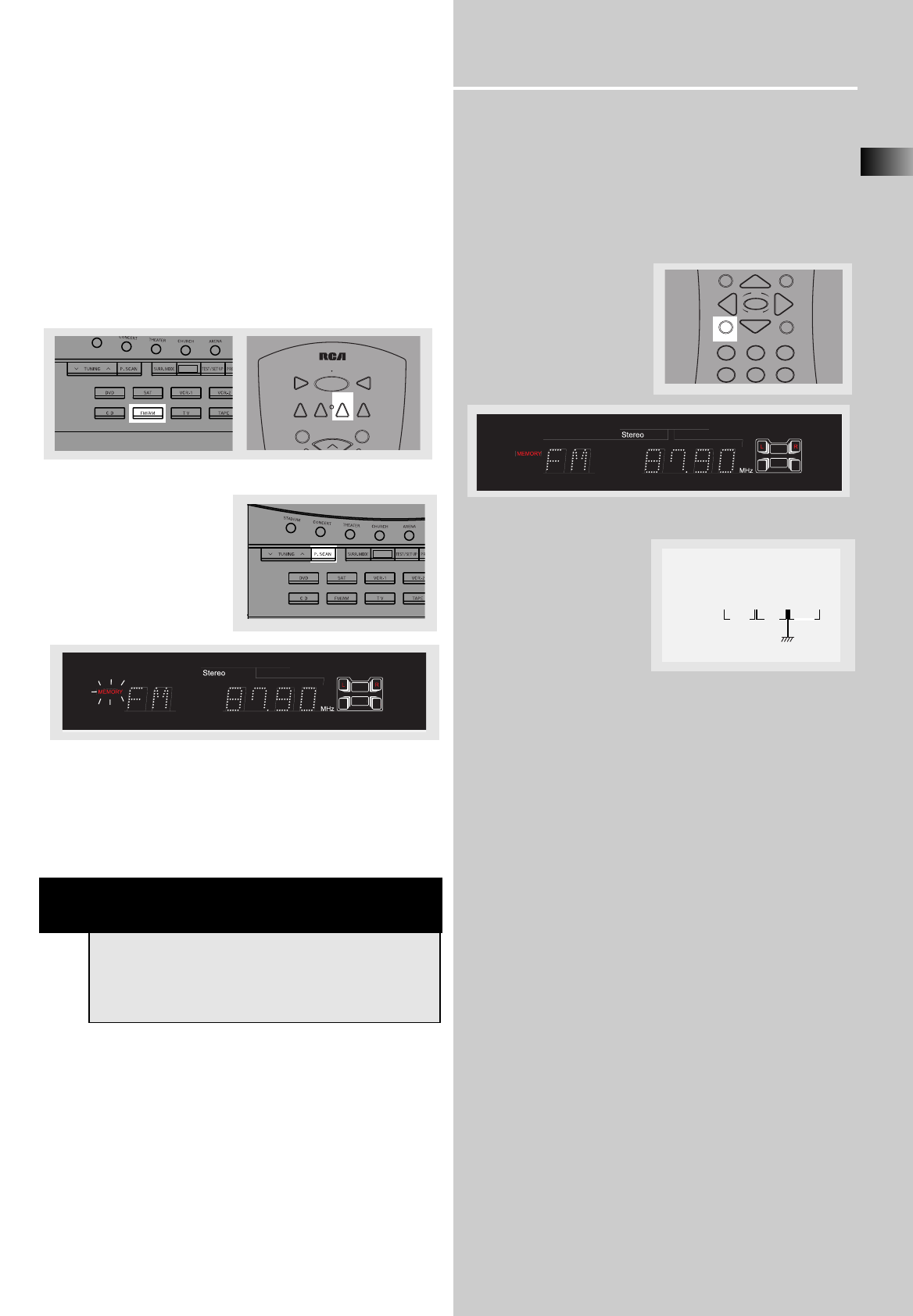
Storing radio stations:
The receiver can store up to 30 radio stations in
memory. You can enter every single radio station
yourself or the receiver can store all available radio
station automatically in an ascending order.
Automatic preset storing :
1. Select the band wave by pressing AM/FM
repeatedly
2- Press and hold
P.SCAN for 3 seconds.
“MEMORY” will be dis-
played in red and will
blink during the auto-
matic storing process.
Radio frequencies will be browsed and radio station
stored automatically. When all available radio sta-
tions are stored or if all 30 memory locations are full,
the auto preset will stop.
Manual preset
1. Select the band wave by pressing AM/FM repeat-
edly
2. Tune to a radio station (see "Manual tuning" on
page 16 above for details)
3. Press MENU on the
remote control. "MEMO-
RY" will appear on the
display
4. While the word
"Memory " is still flash-
ing, input your desired
preset number (1-30)
using the numeric keys
on the remote control to
store the radio station.
6 CH.IN
HOME THEATER AV SURROUND RECEIVER RT2280
ifier
TV
ON OFF
VCR1
VCR2
DVD•6 CH
T
SAT•CABLE
AM•FM
C
H
+
APECD
NOTE
Weak signal can affect the "Automatic Preset
Storing function" efficiency. Adjust the antenna
for the best reception for more efficient search.
MENU CLEAR
123
456
INFO•RDS
G
U
I
D
E
•
R
D
M
•
P
T
Y
OK
FUNCTION
AM
LOOP
FM
300‰ FM
75‰
6 CH.IN
HOME THEATER AV SURROUND RECEIVER RT2280
l
ifier
18
Operating your Receiver
Retrieving preset stations
1. Press AM/FM to select tuner mode
2. Rotate MULTI JOG on the receiver or press CH+ or
CH- buttons on the remote to select preset stations.
6 Channel external input
An external decoder (Dts, Dolby Digital, etc…) or a
device with built-in multi-channel decoder and 6
channel output connector (DVD player, TV…) can be
connected to the 6CH input. It is therefore possible to
play any future 6 Channels coding (SACD, DVD
Audio) thanks to this connection. The external
decoder device will send the separated audio infor-
mation to the receiver that will then amplify the sig-
nal and send to appropriate speakers.
To activate 6 Channel external input, press 6 CH on
the receiver or press DVD/6 CH twice on the remote
control.
6 CH.IN
HOME THEATER AV SURROUND RECEIVER RT2280
i
fier
TV
ON OFF
VCR1
VCR2
DVD•6 CH
T
SAT•CABLE
AM•FM
C
H
+
APECD
FUNCTION
MUTE
C
H
+
C
H
-
V
O
L
V
O
L
TAPECD
INFO•RDS
G
O
B
A
C
K
•
D
I
S
K
E
•
R
D
M
•
P
T
SUBWOOFER (8‰)
CENTER SPEAKER (
8
PRE OUT
FRONT L REAR L
FRONT R REAR R
IN IN
ANTENNA
IN OUT IN
MONITOR OUT
DIGITAL INPUT
DVD/CD/SAT
DVD/CD/SAT/TV
OPTICAL
IN OUT
6 CH.IN
A
V SURROUND RECEIVER RT2280
TV
ON OFF
VCR1
VCR2
DVD•6 CH
T
SAT•CABLE
AM•FM
C
H
+
APECD
EN
19
Advanced Sound Control
Sound Enhancement Systems
This receiver is equipped with several built-in sound
enhancement systems.
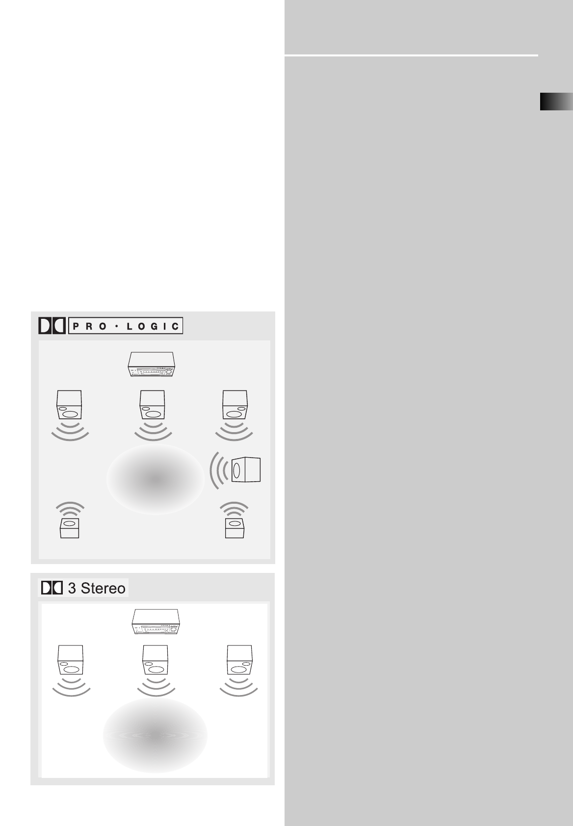
Dolby Pro Logic and Dolby 3 Stereo
This surround system reproduces theater-like sur-
round sound from Dolby-encoded software. The Pro
Logic mode uses the built-in circuit to steer the Left,
Center, Right and Surround channel audio signals and
uses all five speakers and an optional subwoofer to
play decoded Dolby Pro Logic program source, such
as TV and VCR.
The 3 Stereo mode will redirect the Surround signals
to the front left and right speakers when only the
front and center speakers are used.
Use this mode to suit your speaker system configura-
tions (such as size and number of speakers) and type
of program (such as VCR).
Dolby Digital
The Dolby Digital mode lets you enjoy full digital
surround from software processed in the Dolby
Digital format. Dolby Digital provides better sound
quality and more powerful presence than conven-
tional Dolby Surround.
This unit is equipped with Dolby Digital 5.1-channel
so that you can enjoy enhanced full digital surround
sound. Being different from Dolby Pro Logic in which
only four channels ( Front Left, Front Right, Centre
and Rear ) are used, the new system provides stereo
separation of the rear speakers (Rear-Right, Rear-Left
). These 5 channels, together with the subwoofer
channel for bass sounds ( counted as 0.1 channel ),
constitute as 5.1-Channel ( or 6 Channels ) Input for
Dolby Digital that brings you the most sophisticated
sound enjoyment.
Recording Dolby Digital Source
To record from a digital (optical or coaxial) input
using a VCR/Tape that is connected to the receiver,
the sound must be set to stereo first.
Press SURR. MODE to select stereo mode.
If the receiver is set to 5.1 sound information record-
ing from surround speaker, the center speaker will
not be recorded.
Front Left Speaker Front Right Speaker
Subwoofer
Center Speaker
Rear Right Speaker
Rear Left Speaker
Front Left Speaker Front Right Speaker
Center Speaker
Listening
Zone
Listening
Zone
20
Advanced Sound Control
Stereo
The Stereo mode uses the two main channel outputs
from the front speakers. Use this mode if you have
connected the front speakers only.
DSP (Digital Sound Processor)
These digital sound effects resemble sounds in a real
environment such as Stadium, Concert, Theater,
Arena, Church, Club. DSP automatically converts ana-
log audio signals to digital ones which enables you to
adjust the sound without degrading the sound quali-
ty. Different modes will give you different feel of size
and type of listening environment. (Not available in
Dolby Digital (DVD))
Night Mode
By using Dynamic Range Compression technology,
you can enjoy enhanced sound quality by Dolby
Digital at night without interrupting your roommates
or neighbors. While enjoying a Dolby Digital enabled
component (DVD, SAT), you can activate Night Mode
by pressing NIGHT button at the front of the receiver,
and this mode will compress the difference in volume
between normal voices and sounds like explosions.
There are two modes (SOFT, SOFTER) for you to
choose the extents of compression.
Fine Setting of the Components
The receiver has pre-selected the best surround mode
for you once you turn on the unit by pressing the
Source Buttons (like DVD, SAT, CD) directly. The
default surround modes for different components are
as table below.
If you decide to change the surround mode, you can
press the SURR MODE repeatedly to toggle among
the different surround mode choices and select the
one you want.
Dolby Digital/Pro Logic 3 Stereo Stereo
The receiver will keep the last selection in memory.
Input Signal Setting
The receiver defaults to the most convenient settings
for your easiest use (see table).
If your connection is different from the default set-
ting,
1. Select the source
2. Press FUNCTION
3. Rotate MULTI JOG to toggle among optical/ coaxi-
al/ analog to match your connection. Your selection
will be stored automatically.
Every time you press the source button, the input set-
ting (e.g. DVD/ OPTI) will be shown on display for a
few seconds.
Digital Input
Select this setting to play digital signals from a DVD,
CD, LD player, SAT or TV.
Analog Input
Select this setting to play analog signals from a cas-
sette deck, VCR or turntable.
Source/ If Digital Input (optical If Analog Input
Input or coaxial) is selected is selected
DVD Dolby Digital/PRO LOGIC STEREO
SAT Dolby Digital/PRO LOGIC PRO LOGIC
VCR1 N/A PRO LOGIC
VCR2 N/A PRO LOGIC
TV N/A PRO LOGIC
CD STEREO STEREO
TAPE N/A STEREO
TUNER N/A STEREO
6 CH.IN
HOME THEATER AV SURROUND RECEIVER RT2280
V
e
te Amplifier
FUNCTION
DEFAULT INPUT (as seen on display)
Coaxial (SAT/ COAX)
Optical (DVD/ OPTI)
Analog (CD/ ANL)
Analog (VCR1/ ANL)
Analog (VCR2/ ANL)
Built-in Tuner
Analog (TAPE/ ANL)
Analog (TV / ANL)
SOURCE
SAT
DVD
CD
VCR1
VCR2
FM/AM
TAPE
TV
1
2
3
NOTE
Digital input is only available for DVD, SAT, CD
and TV
AVAILABLE INPUT
ANL/Optical/Coaxial
ANL/Optical/Coaxial
ANL/Optical/Coaxial
ANL/ - / -
ANL/ - / -
ANL/ - / -
ANL/ Optical / -
SOURCE
SAT
DVD
CD
VCR1
VCR2
TAPE
TV
EN
21
Advanced Sound Control
Fine Setting of the Speakers
This receiver supports a wide range of speakers and
subwoofers. For optimal surround sound enjoyment,
you need to register the speaker selection settings of
your audio system. If you buy this receiver with
accompanied speaker package, then this step has
been done for you.
Also, to make the surround sound more effective and
suit the acoustic conditions in your listening room,
you need to delay the signal from some of the speak-
ers. Such channel delay compensates for center or
surround speakers that are closer to listening position
than the front speakers. You can make use of the
TEST/ SET UP button to adjust the speakers’ relative
loudness.
The TEST/ SET UP button
You can adjust the relative loudness of the individual
speakers by TEST/ SET UP button. In Dolby modes,
press the button briefly. A short noise will be heard
in the speakers one by one. The speaker having the
noise at that moment will be shown in the display.
You can listen to that speaker and rotate the MULTI
JOG to adjust the level.
Advanced Setting
Factory defaulted Advance setting indication
from VFD
The receiver has defaulted the following distances:
Front speakers (L/R) 15 ft
Center speaker (Cch) 15 ft
Rear speaker (SUR) 10 ft
Speaker Configurations
You can also change the setup of the speakers by
pressing the TEST/ SET UP button until the display
shows L/R SML or L/R LRG which enables you to set
the size of the front speaker.
Available Selections:
Pressing TEST/SETUP repeatedly while the display is
still showing L/R LRG (about 5 seconds), the display
will toggle among: front, center, surround, sub-
woofer, subwoofer phase and speakers’ distance
setup. Set the speaker size or speakers’ distance by
rotating the MULTI JOG.
SUR
SUR
L/R
C ch
L/R
Front
Left
Rear
Left
Rear
Left
Front
Left
Center
Front Speaker selection Large/ Small
Center Speaker selection Large/ Small/ None
Surround Speaker selection Large/ Small/ None
Subwoofer selection Yes/ No
Subwoofer Phase + / -
Front Speaker distance 0-40 ft
Centre Speaker distance 0-40 ft
Rear Speaker distance 0-40 ft
NOTE
• The sub-woofer selection will always be YES
when the main speakers are set to small
(SML).
• For the subwoofer phase setting, it will be
affected by how you locate the subwoofer.
Try both + and - settings and select the one
that has better bass effect.
• If your unit comes with speakers
(RT2280/2250), always set all speakers size to
“small” to protect them and optimize the
sound quality.
22
Advance Sound Control
Use a subwoofer to enjoy optimum sound.
• Subwoofer Phase: Try both settings and select the
sound preferred.
• Speaker distance: For optimum surround experi-
ence measure the distance between the speaker and
your favorite listening position.
1. Press and hold TEST/SET UP for 3 seconds
2. While the VFD display is showing L/R SML, rotate
MULTI JOG to select and release to save setting.
3. Press TEST/SETUP once to move to the next
speaker setting.
4. Repeat step 3 to set up the next speaker
6. When set up is done, wait for 5 seconds to auto-
matically save your settings or press any source key to
save your selection and set up mode.
Speaker Icons
The receiver shows you the speakers’ types and set-
tings on the display with the following icons:
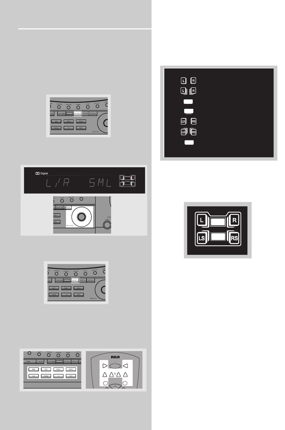
Displaying Program Formats
When a digital source is playing, the receiver will
automatically switch to the proper surround mode
and indicates on the speaker icons on the right-hand
side of the display. (See diagram)
It is important to note, however, that not all Dolby
Digital sources are encoded with the full complement
of five channels plus LFE*. Speaker icons show how
many and which speaker you have enabled (See “Fine
Setting of the Speakers”) and the letters inside the
speaker icons show which channel is present in the
source information. For example, the diagram shown
means you have all the five speakers and subwoofer
enabled and the digital sources you played have five
channels plus LFE complemented.
* LFE stands for Low Frequency Effect. The indication
“LFE” appears if the digital source contains LFE infor-
mation. In this case, the bass signal will be delivered
to the subwoofer, offering more dynamic deep bass
sound effects. If the letter is flashing, the signal is
either too weak or just gone.
Small Front Speakers
Large Front Speakers
Small Center Speakers
Large Center Speakers
Small Rear Speakers
Large Rear Speakers
Subwoofer Present
LFE
C
C
6 CH.IN
D
RECEIVER RT2280
FUNC
T
FUNCTION
E
THEATER AV SURROUND RECEIVER RT2280
6 CH.IN TV
ON OFF
VCR1
VCR2
DVD•6 CH
T
SAT•CABLE
AM•FM
C
H
+
APECD
6 CH.IN
D
RECEIVER RT2280
FUNC
T
C
LFE

EN
23
Care and Maintenance
Troubleshooting Tips
Receiver/Tuner Operation
STEREO indicator is off.
• Adjust the antenna.
The signal is Mono. Severe hum or noise.
• The signal is too weak. Connect an external anten-
na.
Remote Control Operation
The remote control does not operate the unit.
• Another function mode is selected on the remote.
Press the correct Source Button.
• No batteries installed. (included with your system)
Install the batteries before attempting to operate the
remote. Be sure to match the + and - ends of each
battery to the symbols shown in the remote battery
compartment.
• The batteries are weak. Replace all batteries.
• The remote is not pointed at the remote control
sensor on the main unit or there is an obstacle
between the remote and the main unit.
• The remote control is too far from the main unit,
move closer.
General
No audio.
• Make sure the speakers are connected.
• Check the input connections.
• Check the power cord connections.
• Make sure the MUTE indicator on the front panel is
off.
• Make sure the digital setting (optical, coaxial or
analog) is correct.
No audio from one channel.
• Check the speaker level setting.
• Check the speaker wire or cable connections.
Noise occurs when the TV is turned on.
• The TV is too close to the audio system.
Specific instruments sound displaced.
• Check the connections between the receiver and
the speakers if the sound does not match the video.
• Press the Source Button for the video source.
Cleaning the Exterior
• Disconnect the system from AC power before clean-
ing the exterior of the system with a soft dust cloth,
or with a slightly damp leather chamois. Never use
strong solvents.
Equipment Specifications RT2280/RT2250:
AMPLIFIER SECTION:
All 5 channels:
RT2280: each 80W at 8 ohm. 0.9% THD @1 kHz
RT2250: each 50W at 8 ohm. 0.9% THD @1 kHz
Subwoofer channel: 100w at 8Ω(RT2280/RT2250 only)
Muting Attenuation: 65dB
Frequency Response: 40Hz to 20kHz +/-3dB
Signal to Noise Ratio: 65dB (Bypass mode)
VIDEO SECTION:
Input ( Sensitivity/ Impedance ):1Vp-p/ 75ohm
Output (Level/ Impedance): 1Vp-p/ 75 ohm
Frequency Response: 10Hz to 6MHz at +/- 3dB
Signal to noise ratio: 40dB
Crosstalk @3.58MHz: 40dB
AM TUNER SECTION:
Frequency Response: 80Hz – 2kHz +/-6dB
Usable Sensitivity: 800uV/m @ S/N 20dB
Signal to Noise: 38dB
Image Ratio: 27dB @ 1000kHz
IF Rejection: 35dB
FM TUNER SECTION:
Frequency Response: 40Hz – 15kHz +/-3dB
Quieting: 24dBu
Signal to Noise: 60dB(stereo) / 65dB(mono)
Image Ratio: 40dB
IF Rejection: 50dB

24
Remote Codes
CABLE CODES
ABC 5002, 5003, 5004, 5005, 5006, 5009, 5053
ANTRONIX 5008, 5009
ARCHER 5008, 5009, 5010, 5011
CABLETENNA 5008
CABLEVIEW 5008
CENTURY 5011
CITIZEN 5011
COLOUR VOICE 5012, 5013
COMTRONICS 5014, 5015
CONTEC 5016
EASTERN 5017
GARRARD 5011
GC ELECTRONICS 5009
GEMINI 5018, 5019, 5049
GENERAL INSTRUMENT 5003
HAMLIN 5020, 5021, 5022, 5035, 5045
HITACHI 5003
HYTEX 5002
JASCO 5011
JERROLD 5003, 5005, 5007, 5018, 5023,
5024, 5046, 5053
MAGNAVOX 5025
MEMOREX 5026
MOVIE TIME 5002, 5027, 5028
NSC 5002, 5027, 5028
OAK 5002, 5016, 5029
PANASONIC 5048, 5052
PARAGON 5026
PHILIPS 5011, 5012, 5013, 5019, 5025,
5030, 5031, 5032
PIONEER 5033, 5034
PULSAR 5026
RCA 5047, 5049, 5052
REALISTIC 5009, 5049
REGAL 5022, 5035
REGENCY 5017
REMBRANDT 5003
RUNCO 5026
SAMSUNG 5014, 5034
SCIENTIFIC ATLANTA 5006, 5036, 5037, 5038
SIGNAL 5014, 5018
SIGNATURE 5003
SL MARX 5014
SPRUCER 5052
STARCOM 5007, 5018, 5053
STARGATE 5014, 5018
STARQUEST 5018
TANDY 5040
TELEVIEW 5014
TOCOM 5004, 5023, 5041
TOSHIBA 5026
TUSA 5018
TV86 5027
UNIKA 5008, 5009, 5011
UNITED ARTISTS 5002
UNITED CABLE 5053
UNIVERSAL 5008, 5009, 5010, 5011
VIDEOWAY 5044
VIEWSTAR 5015, 5025, 5027, 5040
ZENITH 5026, 5050, 5051
VCR CODES
ADMIRAL 2131
ADVENTURA 2026
AIKO 2027
AIWA 2002, 2026
AKAI 2003, 2004, 2005, 2007, 2008, 2111, 2112,
2113
AMERICAN HIGH 2021
ASHA 2013
AUDIO DYNAMICS 2009, 2010
AUDIOVOX 2014
BELL & HOWELL 2011
BEAUMARK 2013
BROKSONIC 2012, 2025
CALIX 2014
CANDLE 2013, 2014, 2015, 2016, 2017,
2018, 2019
CANON 2021, 2022, 2114
CAPEHART 2020, 2110
CARVER 2062
CCE 2027, 2061
CITIZEN 2013, 2014, 2015, 2016, 2017,
2018, 2019, 2027
COLORTYME 2009
COLT 2061
CRAIG 2013, 2014, 2023, 2061
CURTIS-MATHES 2000, 2002, 2009, 2013, 2016,
2018, 2021, 2022, 2024, 2115
CYBERNEX 2013
DAEWOO 2015, 2017, 2019, 2025, 2026,
2027, 2028, 2110
DAYTRON 2110
DBX 2009, 2010
DIMENSIA 2000
DYNATECH 2002, 2026
ELECTROHOME 2014, 2029
ELECTROPHONIC 2014
EMERSON 2002, 2012, 2014, 2015, 2021, 2024, 2025,
2026,
2029, 2030, 2032, 2033, 2034, 2035, 2036,
2037,
2038, 2039, 2040, 2041, 2042, 2044, 2045,
2047,
2065, 2105, 2113, 2116, 2117, 2130
FISHER 2011, 2023, 2048, 2049, 2050, 2051, 2052,
2118
FUJI 2021, 2119
FUNAI 2002, 2026
GARRARD 2026
GE 2000, 2001, 2013, 2021, 2022, 2053, 2115,
2120
GOLDSTAR 2009, 2014, 2018, 2054, 2121
GRADIENTE 2026
HARLEY DAVIDSON 2026
HARMAN KARDON 2009
HARWOOD 2061
HEADQUARTER 2011
HITACHI 2002, 2055, 2056, 2057, 2107,
2111, 2120, 2122
HI-Q 2023
INSTANT REPLAY 2021
JCI 2021
JC PENNEY 2009, 2010, 2011, 2013, 2014,
2021, 2022, 2055, 2056, 2058,
2059, 2060, 2107, 2118
JENSEN 2055, 2056, 2111
JVC 2009, 2010, 2011, 2018, 2058,
2111, 2123
KENWOOD 2009, 2010, 2011, 2016, 2018,
2058, 2111, 2123
KLH 2061
KODAK 2014, 2021
LLOYD 2002, 2026
LOGIK 2061
LXI 2014
MAGNAVOX 2021, 2022, 2062, 2063, 2104,
2108, 2124
MAGNIN 2013
MARANTZ 2009, 2010, 2011, 2016, 2018,
2021, 2058, 2062, 2064
MARTA 2014
MASUSHITA 2021
MEI 2021

EN
25
Remote Codes
MEMOREX 2002, 2011, 2013, 2014, 2021, 2023, 2026,
2104, 2131
MGA 2029, 2065, 2113
MGN TECHNOLOGY 2013
MIDLAND 2053
MINOLTA 2055, 2056, 2107
MITSUBISHI 2029, 2055, 2056, 2065, 2066, 2067, 2069,
2070, 2071, 2072, 2073, 2074, 2106, 2113,
2123
MONTGOMERY WARD 2075, 2131
MOTOROLA 2021, 2131
MTC 2002, 2013, 2026
MULTITECH 2002, 2013, 2016, 2026, 2053, 2061
NEC 2009, 2010, 2011, 2016, 2018, 2058, 2064,
2076, 2078, 2079, 2111, 2123
NIKKO 2014
NOBLEX 2013
OLYMPUS 2021
OPTIMUS 2014, 2131
OPTONICA 2096
ORION 2035
PANASONIC 2021, 2022, 2109, 2125, 2126, 2127
PENTAX 2016, 2055, 2056, 2107, 2120
PENTEX RESEARCH 2018
PHILCO 2021, 2022, 2062, 2063
PHILIPS 2021, 2062, 2096, 2124
PILOT 2014
PIONEER 2010, 2055, 2080, 2081, 2123
PORTLAND 2016, 2017, 2019, 2110
PROSCAN 2000, 2001
PROTEC 2061
PULSAR 2104
QUARTER 2011
QUARTZ 2011
QUASAR 2021, 2022, 2125
RCA 2000, 2001, 2003, 2013, 2021, 2055, 2056,
2082, 2083, 2084, 2085, 2086, 2087, 2088,
2089, 2090, 2091, 2107, 2115, 2120, 2125
RADIOSHACK/REALISTIC 2002, 2011, 2013, 2014, 2021, 2022, 2023,
2026, 2029, 2049, 2050, 2096, 2131
RADIX 2014
RANDEX 2014
RICOH 2128
RUNCO 2104
SAMSUNG 2005, 2013, 2015, 2033, 2053, 2112
SANKY 2104, 2131
SANSUI 2010, 2092, 2111, 2123
SANYO 2011, 2013, 2023
SCOTT 2012, 2015, 2025, 2032, 2035, 2038, 2065,
2093, 2116
SEARS 2011, 2014, 2021, 2023, 2048, 2049, 2050,
2051, 2055, 2056, 2107, 2118
SHARP 2002, 2017, 2029, 2094, 2095, 2096, 2131
SHINTOM 2004, 2056, 2061, 2098
SHOGUN 2013
SIGNATURE 2002, 2131
SINGER 2021, 2061, 2128
SONY 2002, 2004, 2098, 2099, 2119, 2128
STS 2021, 2107
SYLVANIA 2002, 2021, 2022, 2026, 2062, 2063, 2065,
2124
SYMPHONIC 2002, 2026
TANDY 2002, 2011
TASHIKO 2014
TATUNG 2058, 2111
TEAC 2002, 2026, 2058, 2085, 2111
TECHNICS 2021, 2109
TEKNIKA 2002, 2014, 2021, 2026, 2100, 2129
TMK 2013, 2024, 2047
TOSHIBA 2015, 2049, 2051, 2055, 2065, 2093, 2116
TOTEVSION 2013, 2014
UNITECH 2013
VECTOR RESEARCH 2009, 2010, 2015, 2016
VICTOR 2010
VIDEO CONCEPTS 2009, 2010, 2015, 2016, 2113
VIDEOSONIC 2013
WARDS 2002, 2013, 2014, 2015, 2021, 2023, 2026,
2029, 2055, 2056, 2061, 2096, 2101, 2102,
2103, 2107, 2116, 2131
XR-1000 2021, 2026, 2061
YAMAHA 2009, 2010, 2011, 2018, 2058, 2111
ZENITH 2004, 2098, 2104, 2119, 2128
TV CODES
ABEX 1172
ADMIRAL 1001, 1173
ADVENTURA 1174
AIKO 1016
AKAI 1002
ALLERON 1046
AMTRON 1038
ANAM NATIONAL 1003, 1038
AOC 1004, 1005, 1006, 1007, 1175, 1176
AUDIOVOX 1038
BELCOR 1004
BELL & HOWELL 1001, 1083, 1162
BRADFORD 1038
BROKWOOD 1004
CANDLE 1004, 1006, 1008, 1174
CAPEHART 1175
CELEBRITY 1002
CENTURION 1009
CITIZEN 1004, 1006, 1008, 1016, 1038, 1105, 1171,
1174, 1177
CLAIRTONE 1176
COLORTYME 1004, 1006
CONCERTO 1004, 1006
CONTEC/CONY 1012, 1013, 1014, 1038, 1176
CRAIG 1038
CROWN 1038, 1171
CURTIS MATHES 1000, 1004, 1006, 1015, 1105, 1162, 1171
CXC 1038
DAEWOO 1004, 1005,1006, 1016, 1017, 1018, 1127,
1171
DAYTRON 1004, 1006, 1171
DIMENSIA 1000
DUMONT 1004, 1151
DYNATECH 1178
ELECTROBAND 1002, 1176
ELECTROHOME 1003, 1004, 1006, 1019, 1022
EMERSON 1004, 1006, 1012, 1014, 1023, 1024,
1025, 1026, 1027, 1028, 1029, 1030,
1031, 1032, 1033, 1034, 1035, 1036, 1037,
1038, 1039, 1041, 1042, 1043, 1044, 1046,
1047, 1123, 1124, 1162, 1171, 1176, 1177,
1179, 1191
ENVISION 1004, 1006
FISHER 1048, 1049, 1050, 1051, 1162, 1180
FUJITSO 1046
FUNAI 1038, 1046
FUTURETEC 1038
GE 1000, 1003, 1004, 1006, 1022, 1052, 1054,
1055, 1087, 1164, 1165, 1166, 1167, 1168,
1181
GIBRALTER 1004, 1151
GOLDSTAR 1004, 1005, 1006, 1012, 1019, 1056, 1057,
1058, 1155, 1156, 1171, 1172
GRUNDY 1038, 1046, 1171
HALLMARK 1004, 1006
HARVARD 1038
HITACHI 1004, 1006, 1012, 1013, 1059, 1060, 1061,
1135, 1136, 1137, 1138, 1139, 1140, 1141,
1142, 1143, 1144, 1145, 1146, 1148, 1150,
1179
IMA 1038
INFINITY 1062
JANEIL 1174
JBL 1062
JCB 1002
JC PENNY 1000, 1004, 1005, 1006, 1008, 1022, 1052,
1054, 1058, 1063, 1064, 1072, 1087, 1105,
1128, 1171, 1172, 1181
JENSEN 1004, 1006
JVC 1012, 1013, 1054, 1060, 1065, 1066, 1067,
1089, 1157, 1158, 1159, 1182

26
Remote Codes
KAWASHO 1002, 1004, 1006
KAYPANI 1175
KENWOOD 1004, 1006, 1019
KLOSS NOVABEAM 1068, 1069, 1174, 1183
KTV 1038, 1070, 1171, 1176, 1177
LOEWE 1062
LOGIK 1083
LUXMAN 1004, 1006
LXI 1000, 1006, 1049, 1062, 1071, 1072, 1073,
1162, 1181
MAGNAVOX 1004, 1006, 1008, 1019, 1062, 1068, 1069,
1074, 1075, 1076, 1077, 1088, 1089, 1130,
1131, 1132, 1133, 1134, 1183, 1184
MAJESTIC 1083
MARANTS 1062
MARANTZ 1004, 1006, 1062, 1078
MEGATRON 1006, 1059
MEI 1176
MEMOREX 1001, 1006, 1082, 1083, 1162
MGA 1004, 1005, 1006, 1019, 1022, 1051, 1079,
1080, 1082
MIDLAND 1054, 1151, 1171, 1172, 1181
MINUTZ 1052
MITSUBISHI 1004, 1005, 1006, 1019, 1022, 1051, 1079,
1080, 1081, 1082, 1082, 1083, 1125
MONTGOMERY WARD 1083
MOTOROLA 1003, 1173
MTC 1004, 1005, 1006, 1105, 1176, 1178
MULTITECH 1038, 1178
MULTIVISION 1084
NAD 1006, 1071, 1072, 1185
NEC 1003, 1004, 1005, 1006, 1089
NIKKO 1006, 1016
NTC 1016
ONWA 1038
OPTIMUS 1185
OPTONICA 1095, 1173
ORION 1035, 1191
PANASONIC 1003, 1054, 1062, 1170
PHILCO 1003, 1004, 1005, 1006, 1008, 1012, 1019,
1062, 1068, 1069, 1074, 1075, 1077, 1183,
1184
PHILIPS 1003, 1004, 1008, 1012, 1019, 1062, 1068,
1069, 1074, 1075, 1076, 1086, 1087, 1088,
1089
PILOT 1004, 1171
PIONEER 1004, 1006, 1090, 1091, 1092, 1179, 1185
PORTLAND 1004, 1005, 1006, 1016, 1171
PRICE CLUB 1105
PRISM 1054
PROSCAN 1000, 1181
PROTON 1004, 1006, 1012, 1093, 1175
PULSAR 1151
PULSER 1004
QUASAR 1003, 1054, 1070, 1094
RADIO SHACK/REALISTIC 1000, 1004, 1006, 1012, 1038, 1049, 1095,
1162, 1171, 1172
RCA 1000, 1003, 1004, 1005, 1006, 1007, 1019,
1096, 1098, 1099, 1100, 1101, 1102, 1103,
1129, 1179, 1181, 1187, 1188, 1190
RHAPSODY 1176
RUNCO 1151
SAMPO 1004, 1006, 1171, 1172, 1175
SAMSUNG 1004, 1005, 1006, 1012, 1015, 1019, 1104,
1105, 1106, 1171, 1172
SAMSUX 1171
SANSUI 1191
SANYO 1004, 1048, 1049, 1050, 1080, 1107, 1108,
1162, 1169, 1180, 1189
SCOTCH 1006
SCOTT 1004, 1006, 1012, 1024, 1035, 1038, 1046
SEARS 1000, 1004, 1006, 1013, 1019, 1046, 1048,
1049, 1050, 1051, 1066, 1071, 1072, 1109,
1110, 1162, 1180, 1181, 1189
SHARP 1004, 1006, 1012, 1029, 1095, 1111, 1112,
1113, 1122, 1171, 1173
SHOGUN 1004
SIGNATURE 1001, 1083, 1115
SIMPSON 1008
SONIC 1176
SONY 1002
SOUNDESIGN 1004, 1006, 1008, 1038, 1046
SQUAREVIEW 1189
SSS 1004, 1038
STARLITE 1038
SUPRE-MACY 1174
SUPREME 1002
SYLVANIA 1004, 1006, 1008, 1019, 1062, 1068, 1069,
1074, 1075, 1076, 1077, 1088, 1116, 1161,
1183, 1184
SYMPHONIC 1033, 1038, 1189
TANDY 1173
TATUNG 1003, 1178
TECHNICS 1054
TECHWOOD 1004, 1006, 1054
TEKNIKA 1004, 1005, 1006, 1008, 1012, 1013, 1016,
1038, 1046, 1076, 1082, 1083, 1105, 1170,
1171
TELECAPTION 1117
TMK 1004, 1006
TOSHIBA 1049, 1071, 1072, 1089, 1105, 1109, 1117,
1118, 1160, 1162
TOTEVISION 1171
UNIVERSAL 1052, 1087
VICTOR 1066, 1182
VIDTECH 1004, 1005, 1006
VIKING 1174
WARDS 1000, 1001, 1004, 1005, 1006, 1019, 1024,
1033, 1046, 1052, 1062, 1069, 1074, 1075,
1076, 1083, 1087, 1088, 1095, 1119, 1120,
1184
YAMAHA 1004, 1005, 1006, 1019
ZENITH 1004, 1083, 1151, 1152, 1153, 1154
Satellite Receivers
CHAPPARAL 5056, 5057
DRAKE 5058, 5059
GE SATELLITE RECEIVER 5000, 5001
GENERAL INSTRUMENTS 5060, 5061, 5062
PANASONIC SATELLITE RECEIVER
5075
PRIMESTAR DBS 5076
PROSCAN SATELLITE RECEIVER 5000, 5001
RCA SATELLITE RECEIVER 5000, 5001
REALISTIC 5063
SONY SATELLITE RECEIVER 5072
STS1 5064
STS2 5065
STS3 5066
STS4 5067
TOSHIBA 5068
TOSHIBA SATELLITE RECEIVER 5073
UNIDEN SATELLITE RECEIVER 5069
Audio (RCA/Dimensia only)
AM/FM 4003
AUX 4004
PHONO 4005
CD 4007
TAPE 4006
Laser disc Players
PROSCAN 2001
RCA 2001

EN
27
Limited Warrranty (US)
What your warranty covers:
• Defects in materials or workmanship.
For how long after your purchase:
• One year from date of purchase for labor and parts
• The warranty period for rental units begins with the first
rental or 45 days from date of shipment to the rental firm,
whichever comes first.
What we will do:
• Pay any Authorized RCA Audio Service Center the labor
charges to repair your unit.
• Pay any Authorized RCA Audio Service Center for the
new or, at our option, refurbished replacement parts
required to repair your unit.
How you get service:
• Take your unit to any Authorized RCA Audio Service
Center. To identify your nearest Authorized RCA Audio
Service Center, ask your dealer, look in the Yellow Pages, or
call 1-800-336-1900.
• Show the Authorized Service Center Representative your
evidence of purchase date or first rental.
• Pick up your unit when repairs are completed.
• Proof of purchase in the form of a bill of sale or receipt-
ed invoice which is evidence that the product is within the
warranty period must be presented to obtain warranty
service. For rental firms, proof of first rental is also
required.
What your warranty does not cover:
• Customer instruction. (Your Owner’s Manual describes
how to install, adjust, and operate your unit. Any addition-
al information should be obtained from your dealer.)
• Installation and related adjustments.
• Signal reception problems not caused by your unit.
• Damage from misuse or neglect.
• Cleaning of audio heads.
• Batteries.
• A unit that has been modified or incorporated into other
products or is used for institutional or other commercial
purposes.
• A unit purchased or serviced outside the U.S.A.
• Acts of nature, such as but not limited to lightning dam-
age.
Product Registration:
• Please complete and mail the Product Registration Card
packed with your product. It will make it easier to contact
you should it ever be necessary. The return of the card is
not required for warranty coverage.
Limitation of Warranty:
• THE WARRANTY STATED ABOVE IS THE ONLY WAR-
RANTY APPLICABLE TO THIS PRODUCT. ALL OTHER
WARRANTIES, EXPRESS OR IMPLIED (INCLUDING ALL
IMPLIED WARRANTIES OF MERCHANTABILITY OR FIT-
NESS FOR A PARTICULAR PURPOSE) ARE HEREBY DIS-
CLAIMED. NO VERBAL OR WRITTEN INFORMATION
GIVEN BY THOMSON MULTIMEDIA INC., ITS AGENTS
OR EMPLOYEES SHALL CREATE A GUARANTY OR IN
ANY WAY INCREASE THE SCOPE OF THIS WARRANTY.
• REPAIR OR REPLACEMENT AS PROVIDED UNDER THIS
WARRANTY IS THE EXCLUSIVE REMEDY OF THE CON-
SUMER. THOMSON MULTIMEDIA INC. SHALL NOT BE
LIABLE FOR INCIDENTAL OR CONSEQUENTIAL DAM-
AGES RESULTING FROM THE USE OF THIS PRODUCT OR
ARISING OUT OF ANY BREACH OF ANY EXPRESS OR
IMPLIED WARRANTY ON THIS PRODUCT. THIS DIS-
CLAIMER OF WARRANTIES AND LIMITED WARRANTY
ARE GOVERNED BY THE LAWS OF THE STATE OF INDI-
ANA. EXCEPT TO THE EXTENT PROHIBITED BY APPLIC-
ABLE LAW, ANY IMPLIED WARRANTY OF MER-
CHANTABILITY OR FITNESS FOR A PARTICULAR PUR-
POSE ON THIS PRODUCT IS LIMITED TO THE APPLICA-
BLE WARRANTY PERIOD SET FORTH ABOVE.
How State Law relates to warranty:
• Some states do not allow the exclusion nor limitation of
incidental or consequential damages, or limitations on how
long an implied warranty lasts, so the above limitations or
exclusions may not apply to you.
• This warranty gives you specific legal rights, and you also
may have other rights that vary from state to state.
If you purchased your unit outside the United
States:
• This warranty does not apply. Contact your dealer for
warranty information.
Service calls which do not involve defective materials
or workmanship are not covered by this warranty.
Costs of such service calls are the sole responsibility
of the purchaser.

28
Limited Warranty (Canada)
What your warranty covers:
• Defects in materials or workmanship.
For how long after your purchase:
• One year from date of purchase for labor and parts
• The warranty period for rental units begins with the first
rental or 45 days from date of shipment to the rental firm,
whichever comes first.
What we will do:
• Pay any Authorized RCA Audio Service Center the labor
charges to repair your unit.
• Pay any Authorized RCA Audio Service Center for the
new or, at our option, refurbished replacement parts
required to repair your unit.
How you get service:
• Take your unit to any Authorized RCA Audio Service
Center. To identify your nearest Authorized RCA Audio
Service Center, ask your dealer, look in the Yellow Pages, or
call 1-800-336-1900.
• Show the Authorized Service Center Representative your
evidence of purchase date or first rental.
• Pick up your unit when repairs are completed.
• Proof of purchase in the form of a bill of sale or receipt-
ed invoice which is evidence that the product is within the
warranty period must be presented to obtain warranty
service. For rental firms, proof of first rental is also
required.
What your warranty does not cover:
• Customer instruction. (Your Owner’s Manual describes
how to install, adjust, and operate your unit. Any addi-
tional information should be obtained from your dealer.)
• Installation and related adjustments.
• Signal reception problems not caused by your unit.
• Damage from misuse or neglect.
• Cleaning of audio heads.
• Batteries.
• A unit that has been modified or incorporated into other
products or is used for institutional or other commercial
purposes.
• A unit purchased or serviced outside Canada.
• Acts of nature, such as but not limited to lightning dam-
age.
Product Registration:
• Please complete and mail the Product Registration Card
packed with your product. It will make it easier to contact
you should it ever be necessary. The return of the card is
not required for warranty coverage.
Limitation of Warranty:
• THE WARRANTY STATED ABOVE IS THE ONLY WAR-
RANTY APPLICABLE TO THIS PRODUCT. NO VERBAL OR
WRITTEN INFORMATION GIVEN BY THOMSON MULTI-
MEDIA LTD., ITS AGENTS OR EMPLOYEES SHALL CRE-
ATE A GUARANTY OR IN ANY WAY INCREASE THE
SCOPE OF THIS WARRANTY.
• REPAIR OR REPLACEMENT AS PROVIDED UNDER
THIS WARRANTY IS THE EXCLUSIVE REMEDY OF THE
CONSUMER. THOMSON MULTIMEDIA LTD. SHALL NOT
BE LIABLE FOR INCIDENTAL OR CONSEQUENTIAL DAM-
AGES RESULTING FROM THE USE OF THIS PRODUCT.
EXCEPT TO THE EXTENT PROHIBITED BY APPLICABLE
PROVINCIAL LAW, ANY IMPLIED WARRANTY OF MER-
CHANTABILITY OR FITNESS FOR A PARTICULAR PUR-
POSE ON THIS PRODUCT IS LIMITED TO THE APPLICA-
BLE WARRANTY PERIOD SET FORTH ABOVE.
How Provincial Laws relates to warranty:
• This warranty gives you specific legal rights which are in
addition to statutory warranties that may vary from
Province to Province.
If you purchased your unit outside Canada:
• This warranty does not apply. Contact your dealer for
warranty information.
Service calls which do not involve defective materi-
als or workmanship are not covered by this warran-
ty. Costs of such service calls are the sole responsi-
bility of the purchaser.

STANDBY/ON
THOMSON multimedia Inc.
10330 N.Meridian St.
Indianapolis, IN 46290
© 2001 Thomson multimedia Inc.
Trademark(s) © Registered
Marca(s) © Registrada(s)
Marque(s) © Deposée
55135910 (EN/F/E)
www.rca.com
IMPORTADOR
COMERICALIZADORA THOMSON DE MEXICO S.A. DE
C.V
SIERRA CANDELA NO. 111, PISO 11
COL. LOMAS DE CHAPULTEPEC
DEL. MIGUEL HIDALGO
MEXICO D.F. C.P. 11000
R.F.C. CTM-980723 KS5
