Realistic Marine Radio Dx 75 Users Manual
DX-75 to the manual f1e76a2d-df05-415e-8a3d-666268f5c8e7
2015-02-06
: Realistic Realistic-Marine-Radio-Dx-75-Users-Manual-522289 realistic-marine-radio-dx-75-users-manual-522289 realistic pdf
Open the PDF directly: View PDF ![]() .
.
Page Count: 10
Ltstlc-
COM
MUN
I
C
AT I ON
REC
E
IV
E
R
OPERATING
AND
SERVICE
INSTRUCTIONS
M(IDEL
DX.I5
RADIO
SHACK
CORPORATION
DIVISION
OF
TANDY
COR,PORATION

#
INTRODUCTION
The Realistic DX
-75
Communications Receiver is desig'ned
to I rvideboth
the usual "long
wave" standard broadcast
recei)tion and'short wave' international
broadcast
recep-
tion. Therefore, it allows the listener to span the oceans
ald travel around the world by means of radio waves.
of radio waves.
Short wave radr,r signals
arcused forlong distance
trans-
nission becausc
of the way they are reflectcd back to
earth by the ionosplx'rc. Radiation frorn space
(primarily
Ironr thc sut)causes ioniz:ltioll olthe loycrs oI gascs higlt
above thc carth. Shott
wrr,rt
r-aclio signals rvill not pcne-
trate t.hcse tonized gascs; rnst.ead,
they bounce back
to
earth much like a stone skips
across the surface
of quiet
watcr. Variations in thc reflccting charactcristics of tlre
ionosphere due to sun spots, scasons,
time of day, etc.,
producc periods when the skipping of short wave signals
is espccially effective. Sincc nrany of these
periods
oc-
cur h regular cycles the listener may develop a sched-
ule of the best times to listen for sisnals from distant
Darts
of the world.
Listed below are sone of the many types of broadcasts
[hat can be heard on the short wave bands:
Amateur Radio (Ham)
Mobile Radio - Telepirone
Military
Citizens
Band
(CB)
lnt. Short Wave
(Voice
of America, etc.
)
Standard Time Sigrnls (WWV)
GENERAL
Thc Realistic DX-75 is a four band
AM receiver which
covcrs the standarcl broadcast frequencies in one band:
550 to 1600 KC; and the short wave frequencies in
tlrree
bands: 1.6
to 4.4 MC; 4.5 to fl MC; ll to 30MC.
Utilizing four tubes (one multipurpose tube affords five
tube perf
o rmance
)
plus rec tif ie
r, the supe rhetrodyne c i r -
cuit is designed to operate from a 105 to l25volt, 60 cycle
power source. A power transformer eliminates the haz
-
ard of a hot chassis. Housed in a vinyl clad steel taple
model cabinet, the receiver features an eight inch "slide
rule" type dial with continuous tuning of all four bands,
plus bandspread for precise location of signals on tie
busy short wave bands.

SPECIF'ICATIONS
6-5/16 x 14-I/4
x Lt)-17/32
1
5 pounds
550
to 1600
KC - 1.6
to
30
MC
3.5prv
at 20 MC (6
db signal-to-
noisc ratio with 30/s
mocl .
)
6 db
dorvn,
14.5
KC;
60 db
dorvn,
I 25
KC
I
.5 warrs
105 to 125 volts, 60
cps
35 watts
OPERATION
VOLUME Ciockwise rotation of t]le Volurne control
knob turns on powcl and increascs
volume.
BAND SE,LECTOR Rotation of the Band
Selector knob
switches antenna and local oscillator circuits for the var-
ious tuning bands. Index numbers are located near the
knob and at each end of the diai.
TUNING Rotation of the Tuning knob causes
the main
tuning indicator (red) to move across the dial .
BANDSPREAD Rotation of the Bandspread
loob affects
a fine tuning adjustmcnt of the reception frequency. Nor-
mally the indicator should be adjusted to the SET position.
After the approximate frequency has been tuned by use of
the rnain tuning lcrob, tl-rc bandspread
adjustrnent gradually
reduces the frequency for pinpoint selection of signals,
BFO Clockwise rotation of the BFO control turns on a
Beat !-requency
Oscillator and increases the % of modu-
lation of the IF signalby tlris oscillator. A CW signal, as
usecl
fol single side band or code telegraphy purposes,
contains no modulation and must be modulated in the re-
ceiver for proper reception (Note: settings in the lov/er
range of this control may also improve reception of weak
signals other than CW type).
ANL ON ln rfie up position this slide switch activares
the Automatjc Noise Limiter circuits designed to mini-
mize background noise, static, etc. Operation in the
downposition may benecessary for reception of the very
weak signals since the noise limiter suppresses all low-
er level signals.
REC
/ STBY The receiver may be silenced by moving
this slide switch to the STBY position witiout actually
turning off power to the nrbes. Switching back to tfie REC
position instantly returns tlle receiver to normal opera-
tion without warTn-up or retuning.
PHONE This jack provides aconnectionforheadphones
(50 to 1000 ohms) which automatically silences tlre inter-
nal speaker. The Volume control functions as usual to
vary the volume at tie headphones.
Ditncnsions
Wcight (net)
Frequency Rangc
Sens itivity
Selectivity
Audio Orltput
Input Voltage
Power Consumption
INSTALLATION
Choice of a location for tlrc rece iver may bc subject to
several considerations. Tlrese include the arrangement
oI lurnitur-c in thc roon, thc comfort ancl convicncc of tl'rc
listencr, and acccss to a good electrical ground and an
outside antenna. MarT hours of listening enjoyrnent arc
available from a short wave ll:cciver soitis recommend-
ed that the selection of a location for the DX-75 be
be carefully made,
The antenna for standard broadcast is self-contained,
however, an outside antenna is required for distance re-
ception on the short wave bands. As a general rule an
outside antenna should be as high as practical and as long
as possible (up to I00 ft.) for best reception of short wave
signals. The antenna should be mounted away from power
lines, trees, buildings, etc. , and should be attached to
its supports by glass orceranric insulators. No. 12 to
16 ga. copper covered steel wire (uninsulated) is best for
both the antenna and the down lead. A lightening arrestor
should be connected to the down lead for protection against
storm damage. For additional information on antenna
design refer to 'A. R. R. L. Antenna Book" published by
American Radio Relay League, or to any of the many other
antenna handbooks currently available.
Connect the down lead from the antenna to the #2 termi-
nal on the rear of the receiver and connect the #l termi-
nal to a good earth ground such as a water pipe. Plug the
power cord into a standard receptacle providing ff7 VAC
power.
t
,l
2

SET TUNING
CAPACITOR
FULLY CLOSEO
SPRING
HERE
3_LooP coRD
3_t/2
TURt{S
AROUNO
SHAFT
LOOP
CORD
FAST
E
FASTE
Fig. IDial Stringing Diagram
SET TUNING
CAPACITOR
FULLY
CLOSEO
G'
MAIN TUNING
DIAL
CORD
(REAR
VIEIV) BAND
SPREAD DIAL
CORD
(
REAR
VIEIY)
LooP coRD 2-t/2-''
TURNS AROUND
SHAFT
,ffit
s
c3
2-25
c4
4-40
c5
4-40
c6
4-40 c7
220
ct5
.OO5Pf
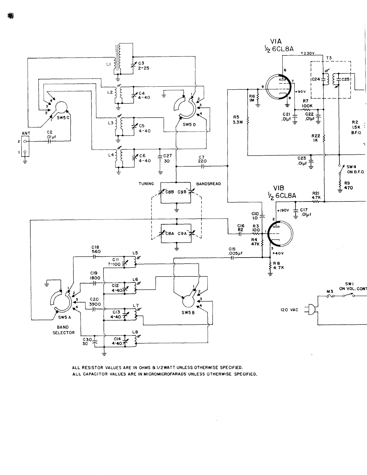
ALL RESISTOR
VALUES
ARE
IN
OHMS
A I/2WATT
UNLESS
OTHERWISE SPECIFIED,
ALL CAPACITOR
VALUES ARE
IN MICROMICROFARADS UNLESS OTHERWISE SPECIFIED.
f3-
){
R2
t.5K :
g.F.o.
Ic27
30 "/ sw
.{ oN
I
{as
I 470
=
4
B.F.O.
VIB
lz,
eCuea
clo
t.o
R3
roo
R4
47K
---
I
I
I
7 lc24
I
reov i
L--
R7
looK
c22 L
.olpt
I
R22
IK
v2
I28A6
c38
rt .oo5l
s
V3
I2AV6 V4
6AQ5A
I c26
I.otpt
- R24
o, sw
3 IOOK
.1 ST8Y.
I REc.
= Rll
2.2M
cRl
EO
3004
R23
4.7K
Rt9
250
stv
4
8.F.O.
CONT
clD
40pl
350v
crc
lOpf
350V
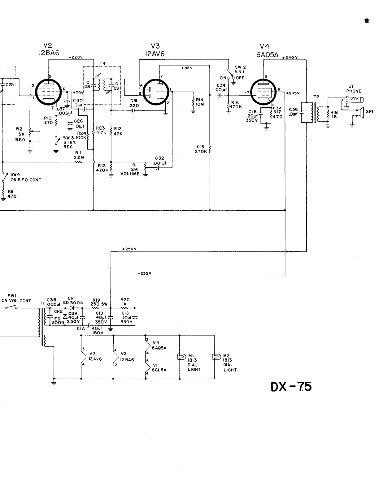
DX
-75
T-
I
I
l
rC
t28
+7ovj JI
PHONE
/ii-\
ey/ ,ri-3-l
t'_J .t@
,-.@
.o@
cs@
cq@
cs@
ceO
L6@
L8@
15@ cu@
crz@
u
z
(O gs@
qq@
o
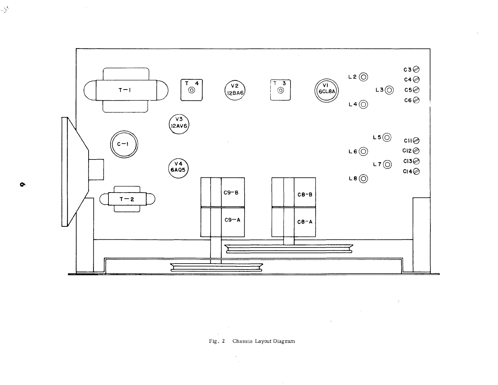
Fig. 2 Chassis Layout Diagram
*
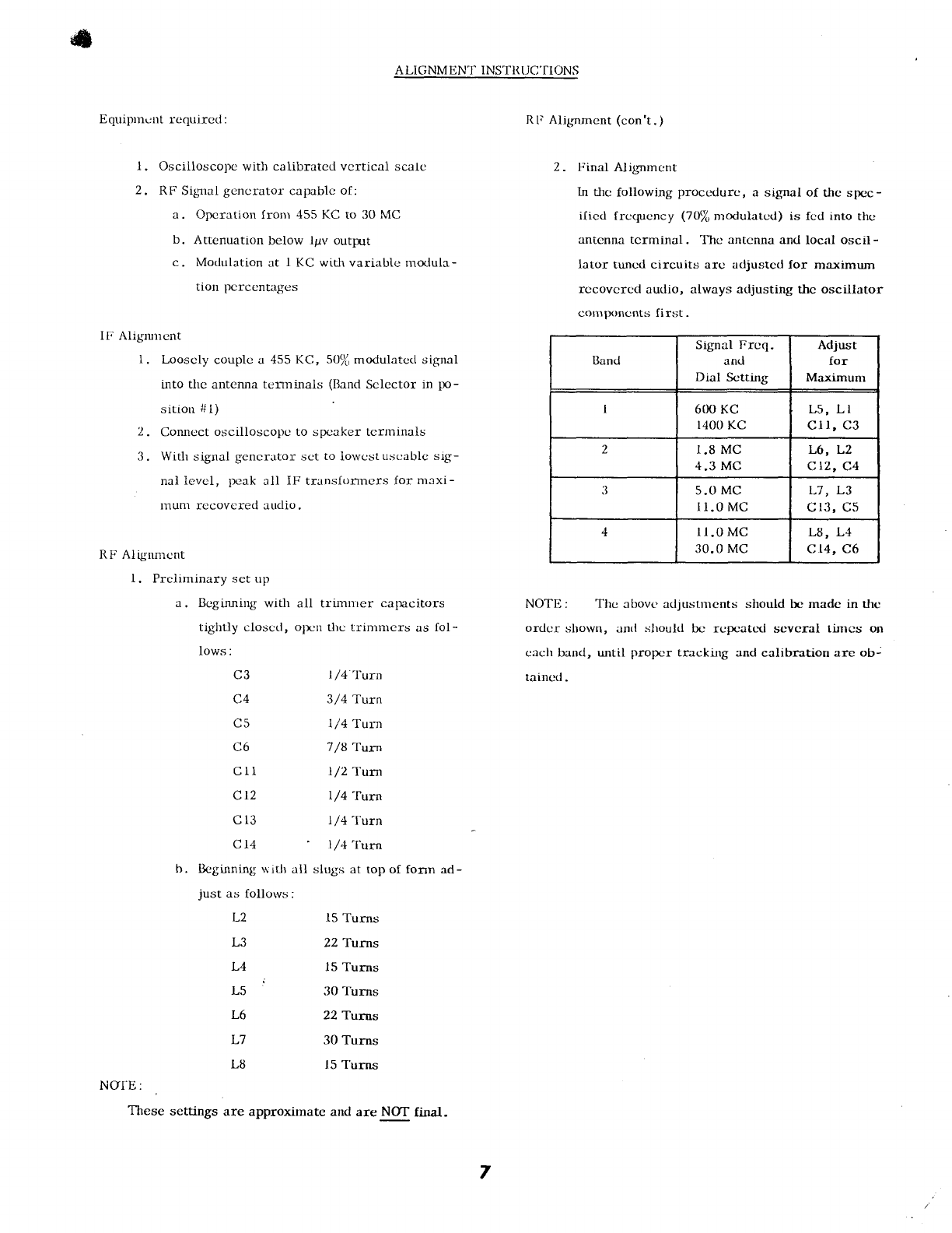
A LIC;NMENT INSTITIJC'f
IONS
Equiptnr:nt rcquirccl :
l. Oscilloscopc with calibratcd vcrtical scalc
2, RF Signal gcncrator- capablc of:
a, Oprcratiol fronr 455 KC to 30 MC
b. Attenuation below lpv output
c. Modulation at I KC wich variablc modula-
tron pcrccnt.rges
IF Alignnrent
1. Looscly couplc a 455 KC, 50/u
modulatcct signal
into thc antenna temrinals (Bancl
Sclector in po-
sition #l)
2. Corulcct oscilloscopc to spcaker tcrminals
3. With signal gcncr.rtor:'sct to lowcstu.scablc sig-
nal levcl, 1rcak all IF-
transfomrers for nrexi-
rnunl recovcred audio.
RF Alignmcnt
l. Prcliminary set up
a, Bcgi,ruring
with all tr-imnrer calrecitors
tightly closcd, o1r:n
thc trinrn)crs as fol-
Iows:
C3 I
/4 'I'urn
C4 3/4 Ttrn
C5 l/4 Tuln
C6 7
/8 Turn
Crl 1/'2
1-urn
Clz l/4'furn
Cl3 l/4'furn
C 14 l,z4
'furn
b. llcginnirg $itlr ail slugs at top of fonn ad-
just as follotvs:
L2
L3
L4
L6
L7
L8
l5 Turns
22 Turns
l5 Turns
30 Turns
22 Turns
30 Turns
15
'I'urns
NO|E:
These settings
RF Alig'nmcnt (con't.)
Z. Final A-lig'nrncnt
ln t-lrc
following proccdurc, a signal of thc spcc-
ilicd frcqucncy (ltJ/u ntoclulat-ctl) is {cd into thc
antenna tcrminal. Thc antcnna and local oscil-
Iator tuncd circuits arc adjustcd for maximum
rccovcrcd audio, always adjusting thc oscillator
cornlxrncnts first.
Iland
Signal Frcq.
and
Dial Sctting
Adjust
for
Maximunr
600 KC
1400
KC L5, LI
cll, c3
2I,8
MC
4.3 MC
L6, L2
ctz, c4
5.0 MC
lr.0 Mc
L7, L3
c13, c5
4lr.0
MC
30.0
MC L8, L4
c 14,
c6
NOTE: The atrovc adjustrncnts should bc madc in tlrc
ordcr shown, anrl shoukl bc rcg.:atc-d scvcral [inrcs on
caclt band, until propcr trackfurg and calibration arc ob-
taincd.
7
are approximate and are NOT final-
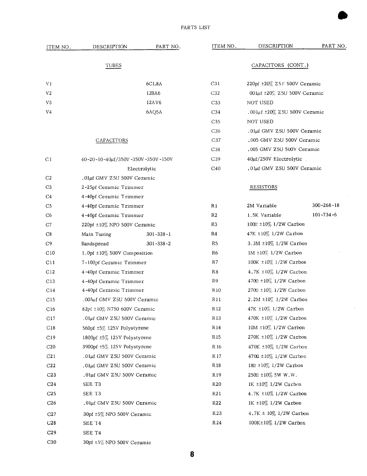
PARTS
LIST
I'TEM
NO. DESCRIPTION PART NO. ITEM NO. DESCRIPTION PART
NO.
VI
v2
V3
V4
TUI]ES
6CL8A
128A6
I2AV6
6AQsA
CAPACITORS
40
-20
-10 -4Oprfl350V
-350V
-350V
-150V
Electrclytic
.0lpf GMV
Z5U
500V Cerarnic
2-2Spf
Ceramic Trirnmer
4
-40pf
Ceramic Trimmer
4-40pf
Ceramic Trimmer
4-40pf
Ceramic Trimmer
22Opt tl\/o NPO 500V
Ceramic
-? I
t- 2)
c33
c34
r.?c
c36
c37
C3B
c39
c40
RI
R2
R3
R4
t(5
R6
R7
R8
R9
RIO
Rtl
R12
Rl3
R14
Rl5
R16
11
r7
R18
Rl9
R20
R2 l
a),
R23
R24
CAPACITORS
(CONT.)
22opt
t20J,
Z5lr 500V Ceramic
00lpf t20fi ZSU 500V Ceramic
NOT USED
.001pt
!2ffi Z5U 500V Ceramic
NOT USED
.0lpf CMV ZsU 500V
Ceramic
.()05
CMV ZsU 500V Ceramic
.005
GMV Z5U 5U0V
Ceramic
40ttf.
/ 250Y Elcctroiytic
.0lpf GMV Z5U 500V
Ceratnic
RESISTORS
2M Variable
l.5K Variable
l00ft
tl0% l/2W Carbon
47K
tlj% l/2W Carbon
3.3M 110%
1/2W Carbon
lM t10% 1/2W
Carbon
l00K tt0% 1/2W Carbon
4.7K !10% I/2W Carlrcn
4700
tl0% l/2W Carbon
27in 1l0t; l/2W Carbon
2.2M tl0T 1/2W Carbon
47K t10% l/2W Carbon
47OK
!I}a/(.
t/2W Carbon
10M
tl0% I/2W Carbon
270K !10% I,/2W Carbon
470K
!1070 l/2W Calllon
47Gt
lI0To I/2W Caitx>n
l&A
tlO% i/2W Carbon
25A1!n% sW W.W.
lK 110%
l/2W Carbon
4.7K !rO%
l/ZW Carbon
rK tl0% l/ZW Carbn
4.7K ! l07o I/2W Carbon
i00Ktl0% r/2W Carbn
CI
C2
C5
C6
C7
rra
rro
cr0
cll
CT2
c13
c14
cl5
c16
c17
cl8
cl9
c20
rtt 1
c22
c23
c24
a)E
c26
c27
c28
c29
c30
300
-268
-
l8
rot -7
34
-6
Main Truring
Bandspread
301
-338 -
r
301
-338 -2
l.Opf t10/6
500V
Composition
/
-
luuill ueramlc I rlmmer
4-4opf
Ceramic Trimmer
4-4opf
Ceramic Trimmer
4-4Opf
Ceramic Trimmer
.005uf GMV Z5U 500V Ceramic
Bzpf
- l0!i N750 600V
Ceramic
.Olpf
GMV
Z5U
500V
Ceramic
560pf
t5lo 125V
Polystyrene
1800pf
15% 125V
Polystyrene
3900pf
t5[ l25V Polystyrene
.0lpf CMV ZSU
500V
Ccramic
.0lpf GMV ZSU
500V
Ceramic
.Olpf GMV
Z5U
500V Ceramic
SEE
T3
SEE
T3
.0lpf GMV ZsU 500V
Ceramic
30pf
t5% NPO
500V
Ceram.ic
SEE
'T4
SEE T4
30pf t57"
NPO
500V
Ceramic
I
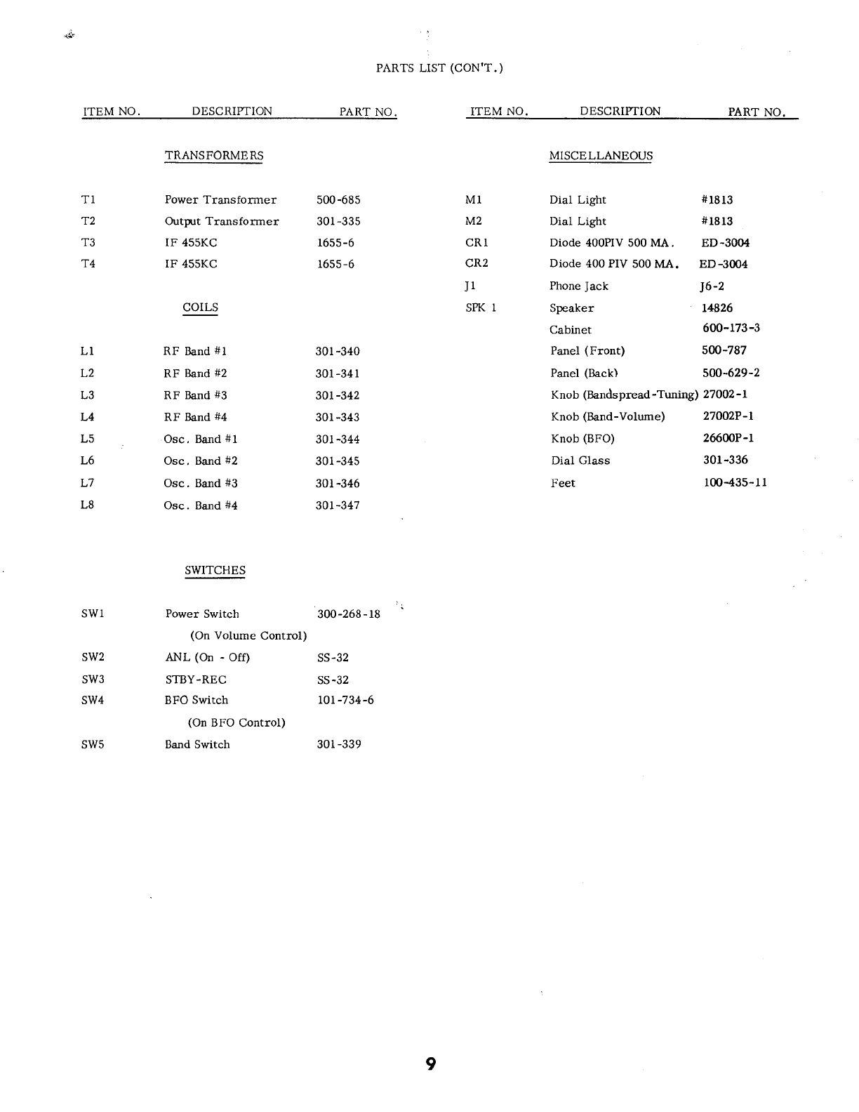
PARTS LIST (CON'T.)
ITEM NO. DESCRIPTION PART
NO. ITEM NO. DESCRIPTION PART NO.
TI
lz
.r?
T4
TRANSFORMERS
Power Traasformer
Outprt Transformer
IF 455KC
IF 455KC
COILS
RF Band
#l
RF Band
#2
RF Band
#3
RF Band
#4
Osc, Band
#l
Osc. Band
#2
Osc. Band
#3
Osc. Band
#4
SWITCHES
Power Switch
(On Volume Control)
ANL (On - Off)
STBY-REC
BFO Switch
(On BFO Control)
Band Switch
500
-685
301
-335
1655-6
1655
-6
MI
M2
CRl
cR2
J1
SPK
T
Diode 400PIV 500 MA. ED-3004
Diode 400 PM00 MA. ED-3004
MISCELLANEOUS
Dial Light
Dial Light
Phone
Jack
Speaker
Cabinet
Panel
(Front)
Panel (Back)
Knob (BFO)
Dial Glass
Feet
#1813
#1813
I6-2
14826
600-r73-3
5W-787
soo-629-2
26600P-r
301
-336
r00-435-1
l
LI
L2
LJ
L4
L5
L6
L7
L8
301
-340
301
-34
l
30L-342
30r
-343
30r-344
301
-345
30i
-346
30r-347
Knob (Bandspread
-Tuning) 27
OO2
- L
Knob (Band-Volume) 27OO2P-1
swl
sw2
sw3
sw4
sw5
300
-268
-
18
ss-32
SS.32
LOr
-7
34-6
301
-339
9
