Realistic Pro 2005 Users Manual
PRO-2005 to the manual 3f6db20d-b078-4fd3-b3ac-ab35a3ed715f
2015-02-06
: Realistic Realistic-Pro-2005-Users-Manual-522299 realistic-pro-2005-users-manual-522299 realistic pdf
Open the PDF directly: View PDF ![]() .
.
Page Count: 35
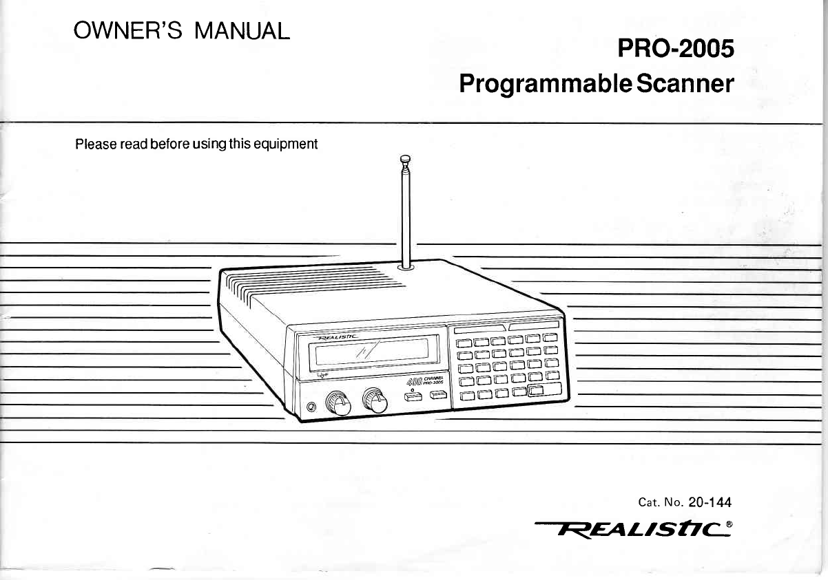
OWNER'S MANUAL PRO-2005
Programmable
Scanner
Please read before
using this equipment
=-=-EE
==s=gq
EEEa4
kwa#ffi
Ee
Cat.
No.
20-144
REAL'St,C
INTRODUCTION
Your
new
Realistic@
pRO-2005
Desk-Top
programmable
Scanner
lets
you
in on
all the
action!
your
scanner
gives
you
direct
access to over 196,000
frequencies
in
nine
ac_
tion-packed
radio
bands including
police,
fire,
ambulance,
aircraft,
ham
radio,
and transportation
seruices,
in
addition
to normal
FM broadcasts,
TV sound,
and CB.
you can
select
up to 400 channels
for your scanner
to scan
through,
and
you can change
your
channel
selection
at
any time.
The secret
of your PRO-2005
scanner
is a custom_
designed
microprocessor-a
computer-on-a-chip-that
al_
lows you
to instantly
select
any frequency
without
having
to change
any crystals.
This
microprocessor
also
givei
your
scanner
special
functions,
such
as:
Liquid
Crystal Display-shows
the channel
and
the fre_
quency
you
have
selected,
as well
as
other information.
Two-Second
Scan Delay-helps
to prevent
your losing
replies
on
a channelwhile you
are
scanning.
Memory
Backup-keeps
the
channel
frequencies
stored
in
your
scanner's
memory
if
a power
failure
occurs.
Lock-Out Function-lets
your scanner
skip over a
specified
channel
or
group
of channels.
Ten Channel
Storage
Banks-allow you to group
your
stored frequencies
so
that
calls
are
easier to identify.
Priority
Channel-helps
to keep
you
from
missing
impor-
tant
calls
on
the
selected
channel.
Direct Frequency
Search-allows you to scan
through
every
available
frequency
to find
interesting
broadcasts.
Monitor
Banks-allow
you to save
up to ten additional
channels
located
during
a
frequency
search.
Sound
Squelch-keeps
the
scanner
from
stopping
on
a
channel
that
is
only
broadcasting
a carrier,
with
no
voice
or
other
sound.
Your PRO-2005
scanner
covers
a
wide
frequency
range:
.25-52OMHz
. 760
- 823.945
MHz
o 851
- 868.945
MHz
o 896
- 1300
MHz
@
1
988 Tandy Corporation.
All Rights
Reserved.
Realistic and Radio Shack are registered trademarkes of randy corporation.
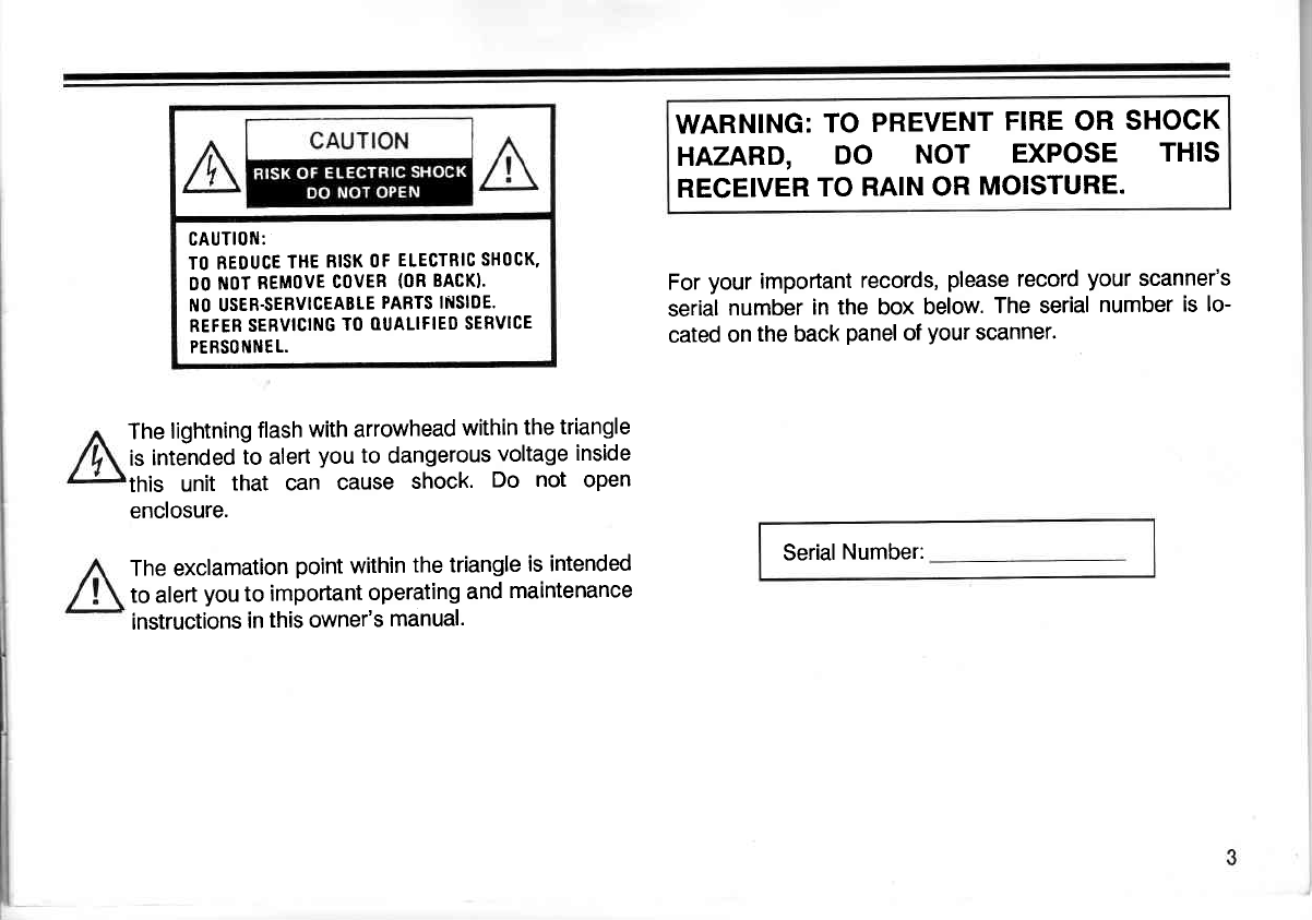
CAUTIOfII:
TO BEDUCE
THE
RISK
OF
ELECTBIC
SHOCK.
DO
ftlOT
REMOVE
COVER
(OR
BACK}.
NO USER.SEBVICEABLE
PARTS INSIDE.
REFER
SEBVICING
TO
OUALIFIEO
SERVICE
PEBS0ttll'lEL.
The
lightning
flash
with arrowhead
within
the
triangle
is
intended
to alert
you
to dangerous
voltage
inside
this unit that can cause shock. Do not open
enclosure.
The exclamation
point
within
the triangle
is intended
to alert
you
to important
operating
and
maintenance
instructions
in
this owner's
manual.
WARNING:
TO
PREVENT
FIRE OR
SHOCK
HAZARD, DO NOT EXPOSE THIS
RECEIVER
TO
RAIN OR
MOISTURE.
For
your
important
records,
please
record
your
scanner's
serial
number
in the box
below.
The serial
number
is lo-
cated
on
the back
panel
of
your
scanner.
Serial
Number:
CONTENTS
A
Quick
Look
at
Your
Scanner ..........................................
5
Preparation .............7
Battery
Installation ..................
T
Power
Sources .......................
g
Connecting the
Antenna ........
g
Using the
Folding Feet
............ ...................
10
Connecting Headphones
................ ........ 10
Connecting
an
Extension
Speaker ..........
10
Connecting
an
External Tape
Recorder
......................
11
Understanding
Your PRO-2005
Scanner .......................
1Z
A Look
at
the
Display ................. 12
A
Look
at the Keyboard
............. ..............
14
Understanding
Channel
Storage Banks
and
Search Banks
Operation
Programming
the PHO-2005
Scanner .........................
Searching for Active
Frequencies
Moving
a Frequency from
a Monitor
Memory
to
a Channel
..................
Understanding Band
Modes
and
Frequency
Steps
.........
Using the
Restart
Switch
Setting the
Volume
and Squelch
Using the
Sound
Squelch Switch
Scanning the
Channels .................
Using the
Delay Feature
...............
Setting the
Scanning
Speed
4
Locking
Out
Channe|s ................
Turning
Banks
On
and Off
......,......
Using the
Priority Feature
Manually
Selecting a
Channel
Dimmer
A
General
Guide to
Scanning
Birdies ....................
Cross
Modulation
..........
Reception
Notes
.........
Guide to the
Action Bands
Typical
Band
Usage
Maintenance
Before
You
Call
for Help
Specifications
.................
24
25
25
25
25
26
26
26
26
27
28
30
31
32
16
17
17
18
21
22
23
23
23
23
24
24
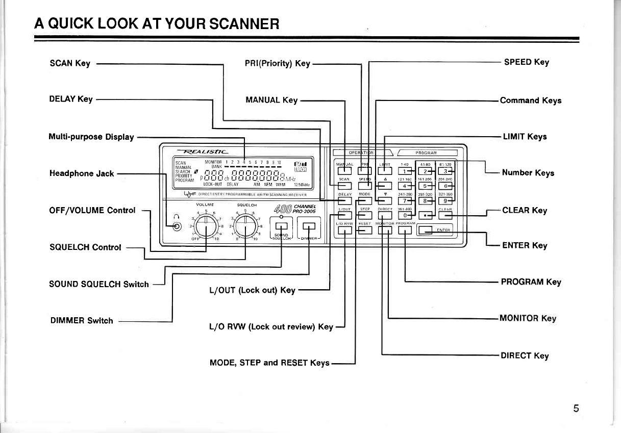
A
QUICK
LOOK
AT YOUR
SCANNER
SCAN
Key
DELAY
Key
Multi-purpose
Display
Headphone
Jack
OFF/VOLUME Control
SQUELCH
Control
SOUND SQUELCH
Switch
DIMMER
Switch
PRI(Priority)
Key
MANUAL
Key
L/OUT
(Lock
out) Key
L/O RVW (Lock out review) Key
SPEED
Key
Command Keys
LIMIT Keys
Number
Keys
CLEAR Key
ENTER
Key
PROGRAM
Key
ll-3),,,
"Tlil
.:.lll-:l:l- lt:i
;;,ffiqfri,
^' " it rt l! D i_t rJ lt i:t D r_t
,-,
piio"'iliu ! Ll Ll Ll \ Ll Ll Ll Ll Ll LlLl i:i
\' /
LOC(
OUT OELAY AM NFM
WFM trsOKHZ H#l# *l#."-=^
voLUVr sourl cH ,a nnlt 'HAMEL
, | " ^ , . +tututPRo2oos
\7
\\t-tt-l
)1" L{J I I LtJ I
i" t.#u"J t"-1."J
MODE,
STEP
and
RESET Keys DIRECT
Key
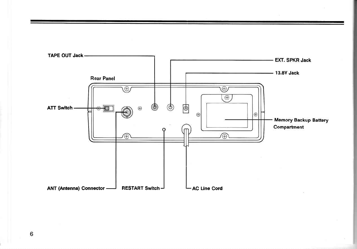
TAPE OUT Jack
Rear
Panel
ATT
Switch
ANT (Antenna) Connector RESTART
Switch AC Line Cord
PREPARATION
BATTERY INSTALLATION
Your
scanner uses a
g-volt
battery for
memory
backup.
For
longest
operation
and best
performance,
we recommend
an alkaline
battery, such as
Radio
Shack's Cat. No. 23-553.
For
best
results, replace the
battery every
six
months.
"BATT"
flashes
in the
display and
beeps sound when the
battery
is low
or
not installed. When
this happens,
replace
or
installthe
battery
immediately.
Caution:
Your
scanner can keep
channels stored
in its
memory for a few minutes
even
with the AC cord un-
plugged
and
the
9-volt battery
disconnected.
But, to avoid
loss
of memory
information,
do not unplug
the scanner
when replacing the
battery.
ln addition, never
leave
a weak
or dead battery
in your
scanner; even
"leakproof"
batteries
can leak
damaging
chemicals.
Battery
life is
about six months when household
AC
power
or automotive DC
power
is
off
for
a prolonged
period
of
time.
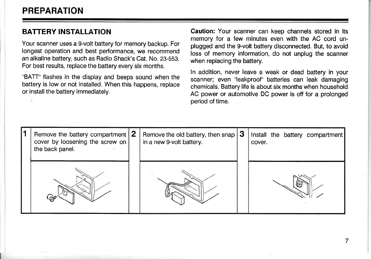
1Remove the
battery compartment
cover by loosening the
screw
on
the
back
panel.
2Remove the
old battery,
then
snap
in
a new
9-volt baftery. 3Install the battery compartment
cover.
POWER
SOURCES
You
can
power
your
scanner
from
the
following
sources:
o A
standard
AC
outlet
o Your vehicle's
battery
(using
an optional
DC power
cable)
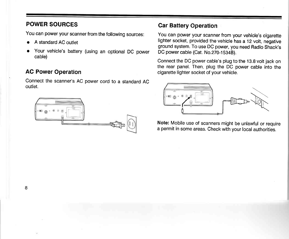
AC Power
Operation
Connect
the
scanner's
AC
power
cord to a standard
AC
outlet.
Gar Battery
Operation
You
can
power
your
scanner
from
your
vehicle's
cigarette
lighter
socket,
provided
the vehicle
has
a 12 volt,
negative
ground
system. To
use
DC
power,
you
need
Radio
Shack's
DC
power
cable
(Cat.
No.270-1b34B).
Connect the DC
power
cable's
plug
to the 13.8
volt
jack
on
the rear
panel.
Then,
plug
the DC
power
cable
into
the
cigarette
lighter
socket
of
your
vehicle.
\
- \'..
nJlfu--llbh.-
ll : "<ll
J\
Note:
Mobile
use
of
scanners
might
be unlawful
or require
a
permit
in
some
areas.
Check with
your
local
authorities.
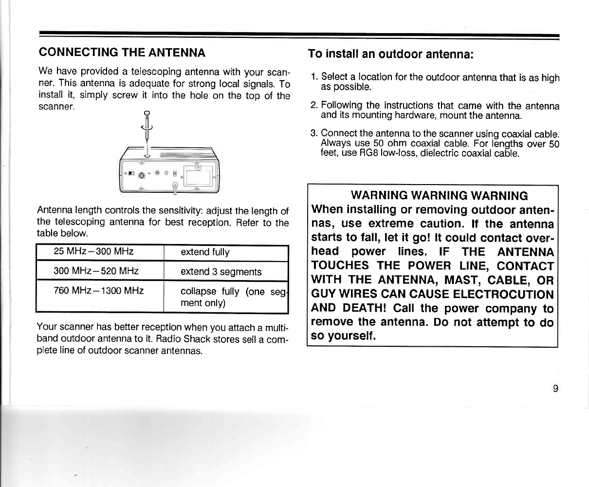
CONNECTING
THE ANTENNA
We
have
provided
a telescoping
antenna with
your
scan-
ner. This
antenna is
adequate for
strong local
signals. To
install
it,
simply
screw
it into
the
hole
on the top
of
the
scanner.
Antenna length
controls the
sensitivity:
adjust the
length
of
the telescoping
antenna for best reception.
Refer
to the
table
below.
Your
scanner has
better reception
when
you
attach
a
multi-
band outdoor
antenna to it. Radio
Shack
stores
sell a com-
plete
line
of outdoor
scanner
antennas.
To install
an
outdoor
antenna:
1.
Select
a
location
for the
outdoor
antenna that is
as
high
as
possible.
2. Following
the instructions
that
came with
the
antenna
and
its
mounting hardware,
mount the
antenna.
3. Connect the
antenna to the
scanner
using coaxial
cable.
Always
uge_ 50 ohm
coaxial
cable.
For
lEngths
over
50
feet,
use RGB low-loss,
dielectric
coaxial
cable.
WARNING
WARNING
WARNING
When
installing
or removing
outdoor
anten-
nas,
use extreme
caution. lf the antenna
starts to fall,
let it go! lt could
contact
over-
head power lines. IF THE ANTENNA
TOUCHES
THE POWER
LINE,
CONTACT
WITH
THE
ANTENNA,
MAST,
CABLE,
OR
GUY WIRES
CAN CAUSE ELECTROCUTION
AND
DEATH!
Call the power
company
to
remove
the antenna. Do not attempt to do
so
yourself.
fl
<J.!)
u
25 MHz-300
MHz extend fully
300
MHz-520MHz extend
3 segments
760 MHz- 1300 MHz collapse
fully
(one
seg
ment
only)
USING THE FOLDING
FEET
Your
scanner's front
feet
are
folding
type.
Use
them
ac-
cording
to the
location
of the
scanner.
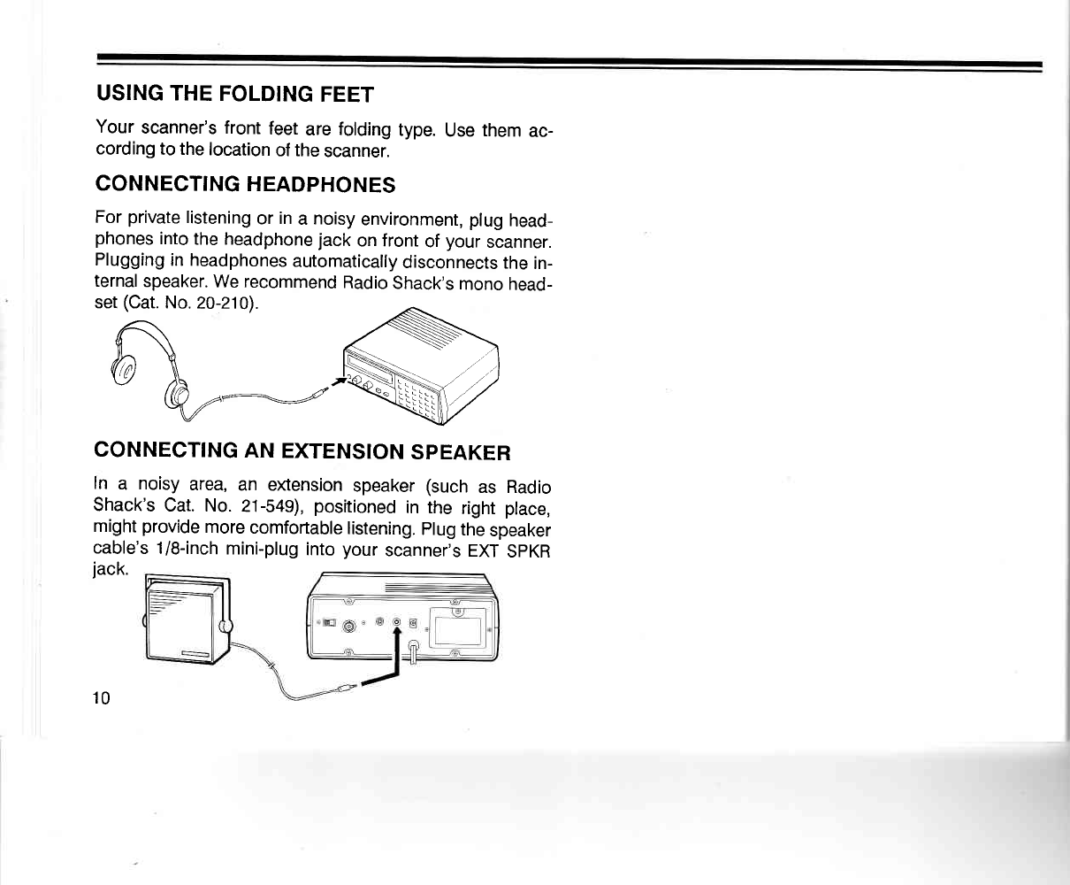
CONNECTING
HEADPHONES
For
private
listening
or
in
a
noisy
environment, plug
head-
phones
into
the headphone
jack
on front
of
your
scanner.
Plugging
in headphones
automatically
disconnects
the
in-
ternal
speaker.
We recommend
Radio
Shack's
mono
head-
set
(Cat.
No.
20-210).
A .s--.'
@ \ JN )
v @,--:::=-:=//""\\ /-\/ \[j/
CONNECTING
AN EXTENSION
SPEAKER
In a noisy
area,
an eltension
speaker
(such
as Radio
Shack's
Cat. No. 21-549),
positioned
in the right
place,
might
provide
more
comfortable
listening.
plug
the
speaker
cable's
1/8-inch
mini-plug
into
your
scanner's
EXT
SPKR
jack.
10
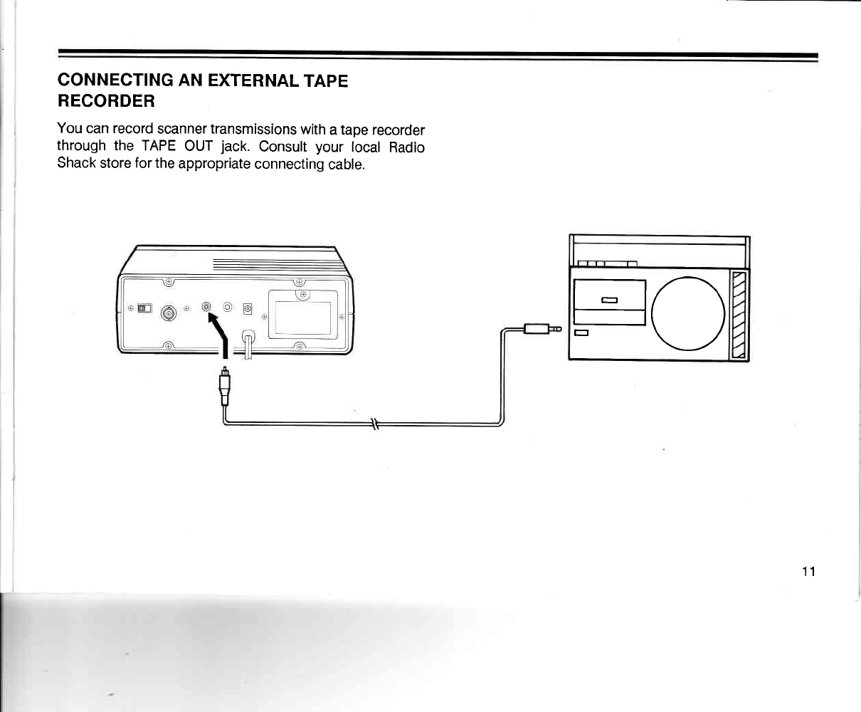
CONNECTING
AN EXTERNAL
TAPE
RECORDER
You
can record
scanner
transmissions
with
a
tape
recorder
through the
TAPE
OUT
jack.
Consult
your
local
Radio
Shack
store
for
the
appropriate
connecting
cable.
FO
11
UNDERSTANDING YOUR
PRO.2OOs
SCANNER
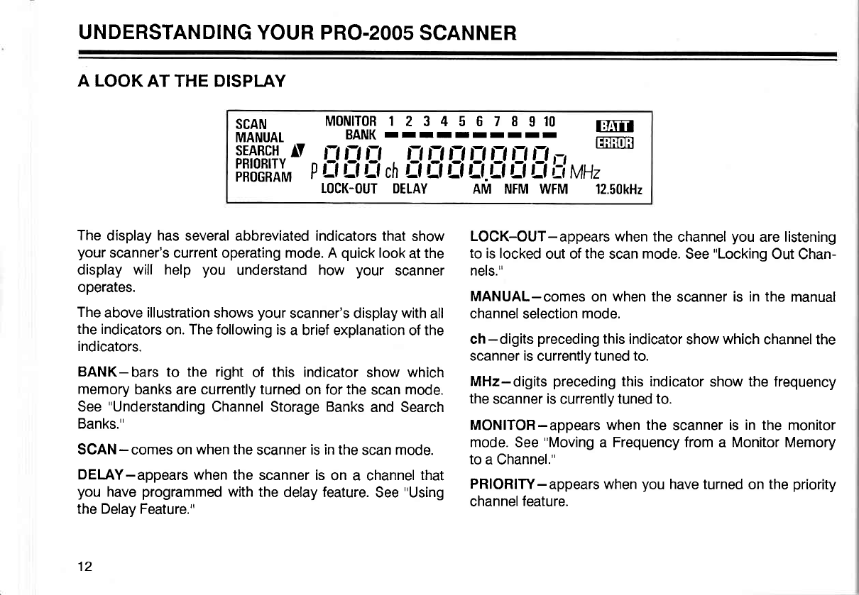
A LOOK
AT THE DISPIAY
The
display
has
several abbreviated indicators that
show
your
scanner's current operating mode. A
quick
look
at
the
display will help you understand how your scanner
operates.
The
above
illustration
shows
your
scanne/s display
with
all
the indicators
on.
The following
is
a brief explanation
of
the
indicators.
BANK-bars
to the right
of this indicator
show which
memory
banks are currently
turned
on
for the
scan mode.
See
"Understanding
Channel Storage Banks
and Search
Banks."
SCAN
- comes on
when the
scanner
is in the
scan mode.
DELAY-appears
when the
scanner is
on a channel
that
you
have
programmed
with the
delay feature.
See
"Using
the Delay Feature."
12
fln'frilu^.
*ot'Ififl
]3::lglE:19 ffi
iiffii/'-
p
l:l
ll fl ,r, tl
il tl Ltri tl L-l fl Lr
vH,*-
I0CK-OUT DETAY AM NFM
WFM 12.50kH2
LOCK-OUT-appears
when the
channel
you
are listening
to
is locked
out of
the
scan
mode.
See
"Locking
Out Chan-
nels."
MANUAL-comes
on
when the
scanner
is in the
manual
channel
selection
mode.
ch
- digits
preceding
this
indicator
show
which
channel the
scanner is
currently
tuned to.
MHz-digits
preceding
this indicator
show the frequency
the
scanner
is
currently
tuned to.
MONITOR-appears when the
scanner
is in the
monitor
mode.
See
"Moving
a Frequency from
a Monitor
Memory
to
a Channel."
PRIORITY-appears
when
you
have turned
on
the
priority
channel
feature.
PROGRAM-appears
when the scanner is ready for
programming.
BAfi-flashes when the
batteries need to be
installed
or
replaced.
P-appears
when
you
are listening
to the
priority
channel.
SEARCH-appears
during a limit
search
or a direct fre-
quency
search.
r and
v
also appear in
the
display to
show
the
direction
of
the
search.
AM, NFM, WFM-shows
which
band mode is currently
selected. See
"Understanding
Band Modes
and
Frequency
Steps."
5, 12.5,
50-shows which frequency
step is currently
selected.
See
"Understanding
Band
Modes
and Frequency
Steps."
13
A LOOK
AT THE KEYBOARD
l-- @mrcN --\ /- m -----l
MANUAL PRI LtMtT 1 40 41-AO A1 nO
EEETIEE
scAN SPEED A t21 t6o 151 200 201 240
Ef]EEEE
OELAY MODE 9 241 2aO 2a1 320 321
360
DEEEETI
L/OUT STEP OIFECT 361
4OO CLEAR
t]f]EEEl E
L/O
RVW FESET MONITOF
PROGRAM/
'E rr -"E-t-;l
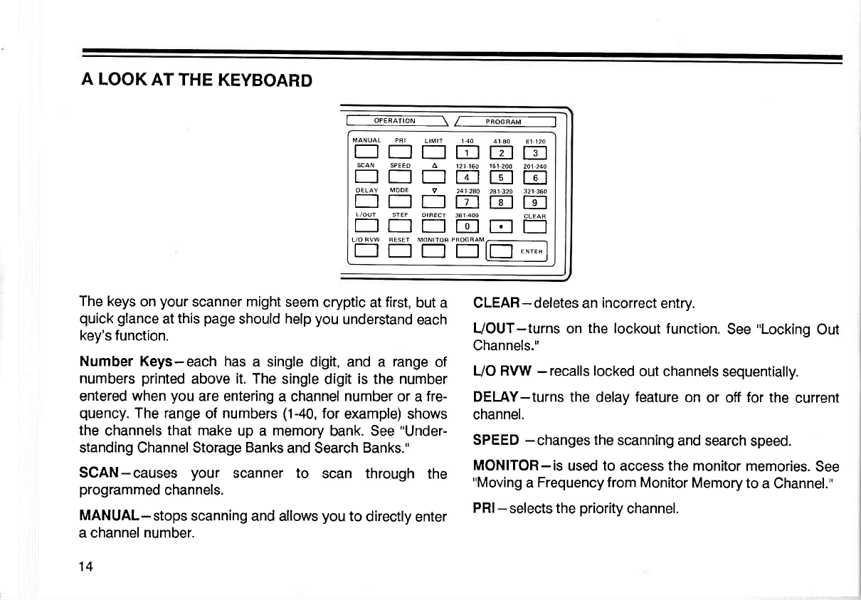
The keys
on
your
scanner
might
seem
cryptic
at
first,
but a
quick glance
at
this
page
should
help
you
understand
each
key's function.
Number Keys-each
has
a single digit, and a range
of
numbers
printed
above
it. The
single digit
is the number
entered
when
you
are entering
a channel
number
or
a
fre-
quency.
The range
of
numbers
(1-40,
for
example) shows
the
channels
that make
up
a memory
bank. See
"Under-
standing Channel Storage
Banks
and Search
Banks."
SCAN-causes
your scanner to scan through
the
programmed
channels.
MANUAL-stops
scanning
and allows
you
to
directly
enter
a channel
number.
14
CLEAR-deletes
an
incorrect
entry.
L/OUT-turns
on the
lockout
function.
See
"Locking
Out
Channels."
UO
RVW
- recalls locked
out channels
sequentially.
DELAY-turns the
delay
feature
on
or off
for
the
current
channel.
SPEED
- changes
the
scanning
and search
speed.
MONITOR-is
used
to
access the monitor
memories.
See
"Moving
a
Frequency from
Monitor Memory
to
a Channel."
PRI-
selects the
priority
channel.
PROGRAM-is
used
when
programming
frequencies into
channels.
ENTER-used to enter
the
frequency
when
programming
channels.
LlMlT,
r, and
v
-are used during
frequency
searching.
See
"Searching
for Active Frequencies."
DIRECT-starts the
direct search.
MODE-changes the
band
mode
in the following
order:
AM_NFM_WFM.
STEP-used
to change
frequency
steps
in the following
order:
5 kHz-12.5
kHz-50 kHz.
RESET-
initializes
band
mode
and
frequency
step.
15
UNDERSTANDING
CHANNEL
STORAGE
BANKS
AND
SEARCH
BANKS
Your
scanner
can store
up
to 410
frequencies.
you
store
each
frequency
in either
a permanent
memory,
called
a
channel,
or a temporary
memory,
called
a monitor.
The
scanner
has 400
channels
and ten
monitor
memories.
To make
it easier
to identify
and
select the
channels
you
want
to listen
to,
channels
are
divided into
ten
groups
of
40
channels.
Each
group
of channels
is
called
a bank.
per-
haps
the
best way
to explain
the
use of memory
banks is
through
a
practical
example.
Suppose
you want to monitor
four different
agencies:
police,
fire,
ambulance,
and
aircraft. As
a
rule,
each
agency
has
several
different
frequencies
they
use for
different
pur-
poses.
The
police
might
have
four
frequencies,
one for
each side
of town.
To
make
it
easier
to quickly
determine
which
agency
you
are listening
to,
you
could
program
the
police
frequencies
starting
with
Channel 1
(Bank
1). Then,
start
the
fire
department
on Channel
41 (Bank
2), am-
bulance
service
on
Channel
81
(Bank
3),
and aircraft fre-
quencies
on
Channel 121
(Bank
4).
Now,
when
you
want
to listen
to
only fire
calls, it
is
simple
to turn
off
Banks
1
and
3
through
10
so
that
only Bank
2 is
scanned. You
could
also
use this
feature
to group
the
channels
by
city or by
county.
Simply
press
the
number
16
corresponding
to
the
bank
you
want
to
turn
on
or off. The
bar below
the number
in
the
display
shows that
bank is
on.
Your
scanner
also has
ten
temporary
monitor
memories.
You
use these
memories
to store frequencies
temporarily,
while
you
decide whether
to save them
in
one
of
the
per-
manent
channels. This
is
handy for
quickly
storing
an ac-
tive
frequency
when
you
are searching
through
an entire
band.
See
"Searching
for Active
Frequencies.,,
When
you
are
in
the
monitor
mode,
the
ten numbers
at
the
top
of
the
display represent
the ten
monitor
memories.
The
flashing
number
shows the
current
monitor
memory.
In
addition,
your
scanner
has ten
search
banks.
you
can
use these
banks to
store
your
selected
limit
search
ranges.
See
"Searching
for
Active
Frequencies.,'
OPERATION
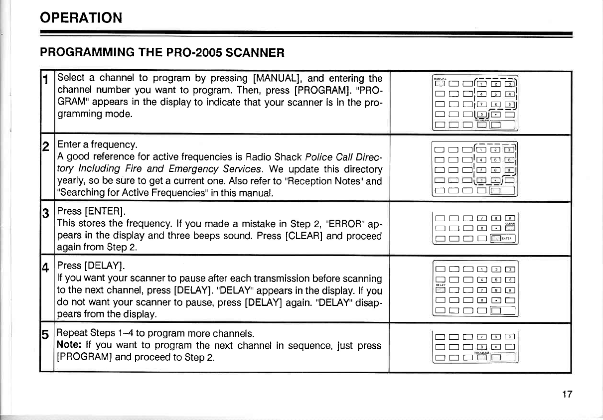
PROGRAMMING
THE
PRO.2OOs
SCANNER
1Select a channel to program
by pressing
[MANUAL],
and
entering
the
channel number
you
want to program.
Then,
press
IPROGRAM].
"PRO-
GRAM"
appears in the
display to indicate that
your
scanner
is in
the
pro-
gramming
mode.
ti'n nfn-6 E
r-r rr rrlr;r rc-r
--t--
EDEiEqE
I rr rr rtrorJlj_.lL__.'l
2Enter
a
frequency.
A good
reference for
active
frequencies
is Radio
Shack
Police
Call
Direc-
tory lncluding
Fire
and Emergency
Seruices. We update
this
directory
yearly,
so be sure to
get
a current
one.
Also refer
to
"Reception
Notes"
and
"Searching
for Active
Frequencies"
in this manual.
nnafma
nrnlno
NEt:]:ETil
Et:]NE
3Press
[ENTER].
This
stores
the frequency.
lf
you
made
a mistake
in
Step
2,
"ERROR"
ap-
pears
in the
display and three
beeps sound. Press
[CLEAR]
and
proceed
again
from
Step
2.
ENNEElE
EEnonff
rr lrr*-l
4Press
[DELAY].
lf
you
want
your
scanner to
pause
after each transmission
before scanning
to the next
channel,
press
[DELAY].
"DEI-AY"
appears
in the
display.
lf
you
do
not want
your
scanner to pause, press
[DELAY]
again.
"DELAY"
disap-
pears
from the
display.
EDT]EEE
f]--EEE
NNNEEE
EEEEEE
rr lrr ll_l
5Repeat
Steps
1-4
to
program
more
channels.
Note:
lf you
want
to program
the next
channel
in
sequence,
just
press
IPROGRAMI
and
proceed
to
Step
2.
Ett-
EEE]
EEN
EICE
E]EE
17
SEARCHING
FOR
ACTIVE FREQUENCIES
Use these
procedures
to
search for
a
transmission.
This
is
helpful
if
you
do not
have
a
reference
to frequencies
in
your
area.
Also,
see
"Guide
to the
Action
Bands"
in this
manual.
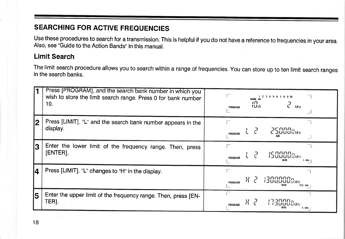
Limit
Search
The limit
search
procedure
allows
you
to
search within
a range
of
frequencies.
You
can
store up to ten
limit
search ranges
in the
search
banks.
1Fress
IHHUGHAMI,
and
the
search
bank number
in which
you
wish
to
store the
limit
search range.
press
0
for
bank number
10.
l2 3 d 5
6 7I9ro I]l
BAiIK .
tn -,
I Ll ch ,: tiln I
f
PRO6SAM
L
2Press
[LlMlT].
"L"
and the
search
bank number
appears in the
display. fIl
| 7 :,Ennn,-l
pB1GRAM L L L -l-Ll Ll Ll t-tMHz
LAM*I
3Enter
the lower
limit
of the
frequency
range.
Then,
press
lENrERl.
I
-t ,r-
r,r,r,L-,
t: | -lt-lt-lt-lt l;,i^jt17
NIM 5 lH!
T
t
PRoGBArvr L
L
4Press
[LlMlT].
"L"
changes
to
,,H"
in
the
display. fIl
t_l 7 t:n-tnnnt-t,-,
pR6cRAM | | L l-l|-lLl.Lll lt-li-ilt7l1t
L NfM 12.5
kHz
5Enter
the
upper limit
of the frequency
range.
Then, press
[EN-
TERI.
I
J t-t
_1nnftr,
t- | | _l.Ll Ll Lt r_i
l\tHz
NrM 5 kH!
f
t_t
PBoGBAM | |
L
1B
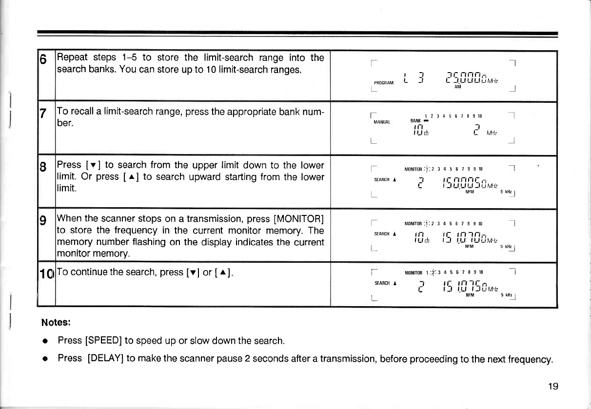
oFlepeat
steps
1-5 to store the limit-search range
into the
search banks. You
can store
up
to 10 limit-search
ranges. I
tt tttttt.-,
t- :t t-t t-t t-t ;,i MH7
arir l
f
r:l
PRocRAM L -l
7To recall
a
limit-search
range,
press
the
appropriate
bank
num-
ber. tz34s 6rgslo I
tt | |
t Lf ch ti. 1,,41, I
rMANUAI
L
BPress
[v] to search
from
the
upper
limit
down
to the lower
limit.
Or
press
Ir] to search
upward starting
from
the lower
limit.
f mororrcn-'i:z3456loslo Ill
srARcH
l -l lt- nnnt- ,-,
i i :lt-lt-lt-l :ti-.i|.A1z
L NFM s
ntl
9When
the
scanner stops
on a
transmission,
press
IMONITOR]
to store the frequency
in the
current monitor memory. The
memory number flashing
on the
display
indicates
the
current
monitor memory.
f uonron',i:234567s9r0 Il
$AncH
l tn tt- tt-l-tn,_,
I
Lf ch | :l l.t-l I Ll;-i t,'tt1/
L_ NtM u utl
1Cfo continue
the
search,
press
[vl or
[^] T uoltront;i:145678910 _l
silRcH^
i i\i1,1\lt*"
I NFM u *t-.1
Notes:
a
a
Press
[SPEED]
to
speed up
or slow down
the
search.
Press
[DEI-AY]
to
make the
scanner
pause
2
seconds after a
transmission,
before
proceeding
to the next
frequency.
19
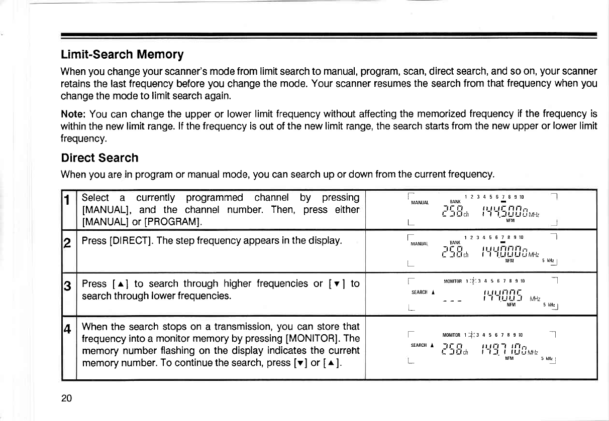
Limit-Search Memory
When
you
change
your
scanner's
mode from limit
search
to manual,
program,
scan, direct search, and so on,
your
scanner
retains the
last frequency
before
you
change
the
mode. Your
scanner
resumes the
search
from that
frequency when
you
change
the mode
to limit
search again.
Note:
You can change
the
upper or lower
limit frequency
without affecting
the memorized
frequency if the frequency is
within the new limit
range. lf the frequency is
out of
the new limit range, the search starts
from the new
upper
or
lower
limit
frequency.
Direct
Search
When
you
are
in
program
or
manual mode,
you
can search up or down
from
the
current
frequency.
1Select a currently
programmed
channel by pressing
IMANUAL],
and the channel
number. Then,
press
either
IMANUALI
or
[PROGRAM].
12345678S10
EANK
-il- fl tt n tr rtn,-,
f: --f L-f ch t-t-t.lttttttir"uz
NFM
Il
J
t-
MANUAT
L
2Press
[DIRECT].
The
step
frequency
appears
in the
display. 1234s
67ueru I]l
BANK
.-lf-
fl lt lt lnnn-,
| :f r:t d | -t -t.t-t t-l t-t Li MHz
NFM u ul1.l
fMANUAI
L
3Press
[r] to search
through higher frequencies
or [v] to
search
through
lower frequencies.
f uotnonr;i::45678s10 _J
srARcH
l ltltll-lt-lt-
| -t -t.t_tt^t:t Urt
NrM u utl
+When
the search
stops on
a transmission,
you
can store
that
frequency into a
monitor memory
by
pressing
[MONITOR].
The
memory number
flashing
on
the
display
indicates the
curreht
memory number.
To
continue
the
search,
press
[v] or
Ir ].
f umron r:i::4 5 6 7I slo -.l
srARcH
l -t t- t-t t t n-t -t t n ,-,
f ---f t-f cn | -t :l I lt ll'.iM]7
NFM ,*tl
20
Notes:
. When
you
press
[DIRECT]
during
limit,
your
scanner
enters
direct
search mode.
o When
you press
a numeric
key
during
a direct
search,
your
scanner
changes to limit
search mode. The
key
you
press
corresponds with
the
limit-search
bank number.
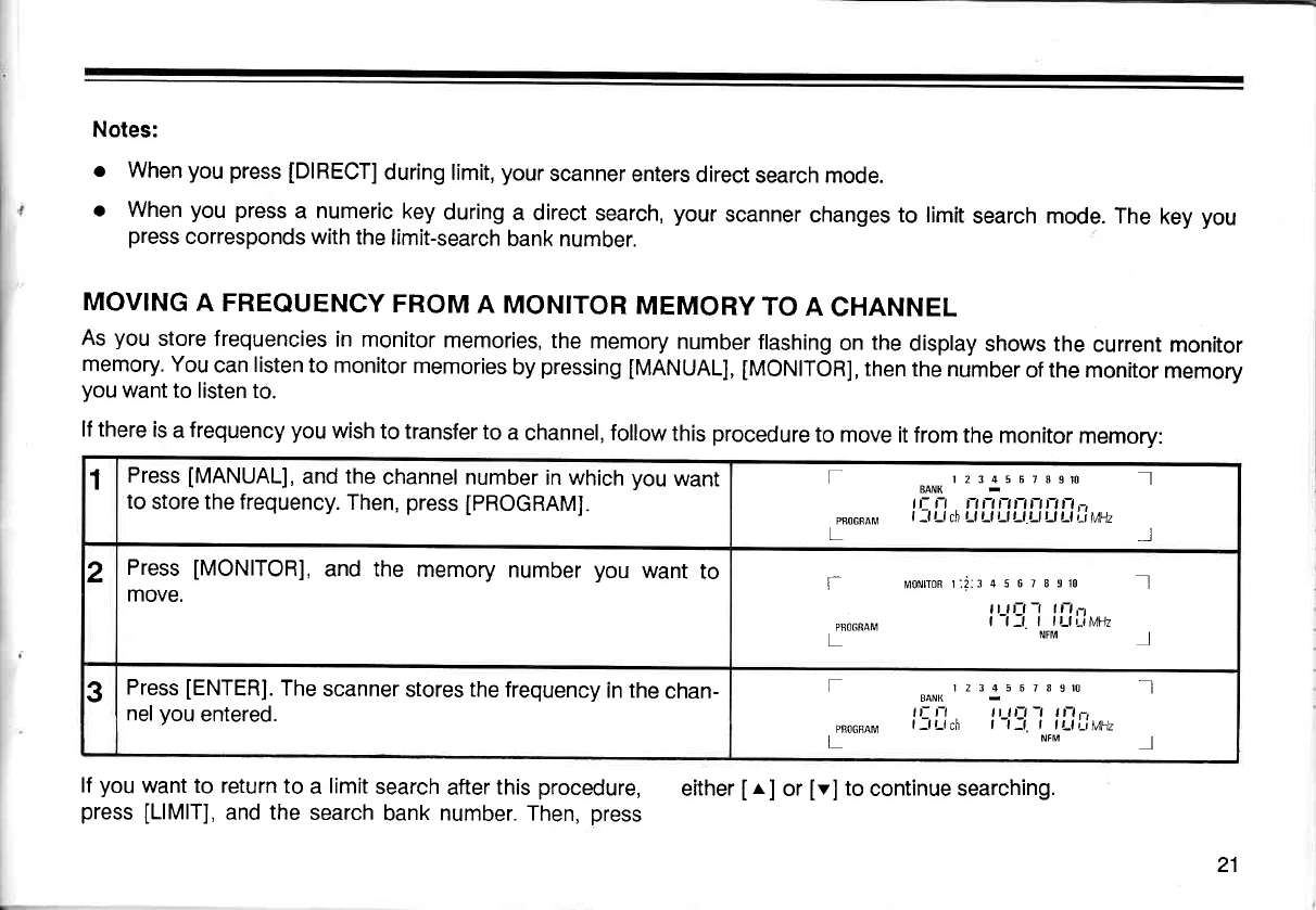
MOVING
A FREQUENCY
FROM
A MONITOR
MEMORY
TO
A CHANNEL
As
you
store frequencies
in
monitor
memories,
the
memory
number
flashing
on
the
display
shows the
current monitor
memory.
You
can
listen
to monitor
memories
by
pressing
IMANUAL],
tMONITORI,
then
the number
of the monitor
memory
you
want
to listen to.
lf there
is
a
frequency you
wish
to transfer
to
a
channel, follow
this
procedure
to move
it from
the monitor
memory:
lf
you
want to return
to
a
limit
search
after
this
procedure, either
Ir. ] or
[v]
to
continue searching.
press
[LlMlT],
and the
search
bank number. Then,
press
1Press
[MANUAL],
and
the
channel number
in
which
you
want
to store the frequency.
Then,
press
[PROGRAM].
f
PBOGffAM
12345 67Bgttl I
BANK
tL n rtftftrtnnn,-t
| -f Ll ch Ll Ll Ll Ll.r-l t-l Ll ri LMz I
2Press
[MONITOR],
and the memory
number
you
want
to
move. l=
PBO6RAM
morurron
r:i:: 4 5 6 7 I g10 I]l
il rrr -r r|-l,-,
t-t:t I tt-tLiMHz
NFM l
3Press
[ENTER].
The
scanner
stores the frequency
in the
chan-
nel
you
entered.
f
PRO6SAM
L
r 2 3 4 5 6 7 8 srt: .]l
EANK
,,- r, n tn -t n-t -,
fJrfch t-t]t. t tr-tLiMnz
NFM ]
21
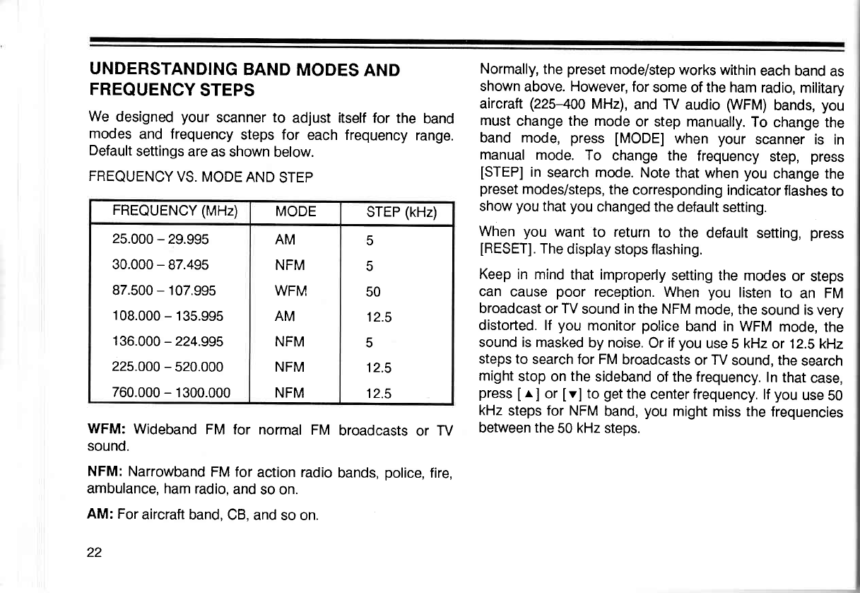
UNDERSTANDING
BAND
MODES
AND
FREQUENCY
STEPS
We
designed
your scanner to adjust itself for the band
modes
and frequency
steps for each frequency
range.
Default
settings
are as shown
below.
FREQUENCY
VS. MODE
AND
STEP
WFM:
Wideband
FM for normal
FM broadcasts
or TV
sound.
NFM: Narrowband
FM for
action
radio
bands,
police,
fire,
ambulance,
ham radio,
and
so on.
AM:
For
aircraft band,
CB, and
so on.
22
Normally,
the
preset
mode/step
works within
each
band
as
shown
above. However, for
some
of
the ham
radio,
military
aircraft
(225400
MHz),
and TV
audio
WFM)
bands,
you
must
change the mode
or step manually.
To
change the
band
mode,
press
[MODE]
when
your scanner is in
manual
mode.
To change the frequency
step,
press
[STEP]
in
search
mode.
Note that
when
you
change the
preset
modes/steps,
the
corresponding
indicator
flashes
to
show
you
that
you
changed the
default
setting.
When
you want
to return
to the
default
setting,
press
IRESETI.
The
display stops flashing.
Keep
in mind
that improperly
setting the
modes
or
steps
can cause
poor
reception.
When
you listen to an FM
broadcast
or TV
sound
in
the NFM
mode, the
sound is very
distorted. lf you
monitor
police
band in WFM
mode,
the
sound is masked
by noise.
Or if
you
use
5
kHz
or 12.5
kHz
steps to search for FM
broadcasts
or
TV
sound, the
search
might
stop on
the
sideband
of
the frequency.
In
that
case,
press
I
r,
] or
Iv] to
get
the
center frequency.
lf
you
use
50
kHz
steps
for NFM
band,
you
might
miss the
frequencies
between the
50
kHz
steps.
FREQUENCY (MHz) MODE STEP
(kHz)
25.000
- 29.995
30.000
- 87.495
87.500
- 107.995
108.000
- 135.995
136.000
-224.995
225.000
- 520.000
760.000
- 1300.000
AM
NFM
WFM
AM
NFM
NFM
NFM
5
5
50
12.5
5
12.5
12.5
USING THE RESTART
SWITCH
The
scanner's
display might lock
up the first
time
you plug
in
and turn
on
your
scanner,
or if the
battery
is left
out for
an e)$ended
period
of time. lf the
display
locks,
use a
pointed
object, like
a paper
clip,
to press
and
release
the
restart
switch
while
power
is
on.
To
clear
all
the
memories,
be sure the
scanner
is turned
on
and:
1. Pressand
hold
[CLEAR].
2. Using
a pointed
object,
press
and release
the
restart
switch.
3. After
confirming that
the
display
goes
blank, release
tcLEARl.
SETTING THE
VOLUME
AND SQUELCH
Turn VOLUME
clockwise
and
SQUELCH
counterclockwise
until you hear a hissing
sound.
Then,
slowly turn
SQUELCH
clockwise
until
the
noise
stops. Leave
VOLUME
set
to
a comfoftable listening
level.
lf
the
scanner
picks
up unwanted
weak
transmissions,
turn
SQUELCH clockwise to
decrease
the
scanner's
sensitivitv
to
these
signals.
USING
THE
SOUND
SQUELCH
SWITCH
lf
the
scanner stops
at a
transmission
during
scan,
search,
or
priority
modes, the
[SOUND
SOUELCH]
switch tets
the
scanner start
scanning again if the
transmission
contains
no
sound
(carrier
only without
modulated
signals).
lf your
scanner
stops
at a frequency
that
has
no sound,
press
[SOUND
SQUELCH]. The
indicator
tights.
tf the
scanner
detects no
sound within
0.5 seconds, it goes
to
the
neld transmission.
When the scanner
receives
a frequency
that contains
sound, it halts
at the frequency.
lf the
sound
ceases, the
scanner stays
on the frequency
for 5 seconds,
and
resumes
scanning.
lf the
carrier
stops, the
scanner
begins
to scan
immediately
if the
delay function
is off, or after 2
seconds if the
delay
function
is
on.
To cancel
sound squelch,
press
[SOUND
SQUELCH]
again.
The indicator
goes
off.
Note: lf a frequency
contains
a transmission
with low
modulation,
the sound
squelch
circuit might
not work
properly.
SCANNING THE
CHANNELS
To begin scanning
channels,
just press
[SCAN].
Your
scanner
scans
through
all
the
channels that
you
have
not
locked
out of
the
banks that
are turned
on.
You
must
set
SQUELCH
so that
you
do not hear
the hissing
sound
be-
tween transmissions.
Be
sure to read
the following
sections
to get the full benefit from the special features
of your
scanner.
USING
THE
DELAY
FEATURE
Many
agencies
use
two-way radio
systems
that might have
a period
of several seconds between a query
and a reply.
To keep
from missing
a reply,
program
a delay
on the
channels
you
identify as
operating
this way. To
program
a
delay,
manually
select
the
channel, and
press
[DEI-AY].
"DELAY"
appears
in the
display.
Now, when
you
are scan-
ning
through
channels,
your scanner
pauses
for two
seconds after
the
completion of each
transmission
on
that
channel
before
resuming
scanning.
Some
radio systems, especially
those
above 800
MHz, use
a special
"trunked"
system.
In these systems,
the transmit-
ter selects an available
frequency each
time the
operator
keys the radio.
Therefore, it is
possible
for the
query
to
be
on one
frequency and
the
reply on another.
To
ensure
the
best
possibility
of
hearing the full reply,
you
want the
scan-
ner to
begin
scanning
immediately when the
first transmis-
sion
ends.
In this
case, select
the channel
manually and
ensure
that
"DELAY"
is not in the
display.
lf
"DELAY"
is indi-
cated,
press
[DEI-AY]
to turn
off
this
feature for that
chan-
nel.
SETTING
THE SCANNING SPEED
Your scanner
has two
different scanning
speeds
- 8 chan-
nels
per
second
and
16
channels
per
second.
To
switch
between
the two scanning speeds,
press
[SPEED]
during
scanning.
LOCKING
OUT CHANNELS
You can
increase the
effective scanning speed
by
locking
out channels
that
you have not
programmed.
Manually
select
the
channel, and
then
press
[UOUT],
so
that
"LOCK-
OUT" appears
in the
display.
This is
also
handy for
locking
out channels
that have
a continuous
transmission, such as
a
weather channel.
You
can still
manually
select
locked-out
channels
for listening.
To
disable
the lock-out function, manually select
the chan-
nel and
press
[L/OUT].
Or,
press
[UO
RW] in manual or
program
mode to
call out
locked-out
channels
one by one.
Then,
press
[UOUT]
again.
Note: You
can
lock
out as
many
channels
as
you
like.
But
there must
be at
least
one channel
that
you
have not
lock-
ed out
in
each
bank.
24
TURNING
BANKS
ON AND
OFF
As
explained
in "Understanding
Channel
Storage Banks
and
Search Banks"
your
scanner
splits the 400
channels
into
ten
banks
of forty
channels
each. The
small
bars
under
the numbers
at the
top of the
display
are
the
bank in-
dicators. You
can turn
each
bank
on and
off,
so
that
all
the
channels
in
a bank
are
either
scanned
or locked
out.
In
scan mode,
press
the number
key for
the
bank
you
want to
turn
on or
off.
lf
the
bank indicator
is
on,
you
have
turned
on the
bank
and the
scanner
scans all the
channels
within
that
bank that
you
have
not
locked
out.
lf
the indicator
is
off, the
scanner
does
not
scan
any of the
channels
within
that
bank. You
can still manually
select
any
channel in
a
bank,
even if
you
have turned
off the
bank. You
cannot turn
off all
banks
- one must
be turned
on.
USING
THE PRIORITY
FEATURE
You
can scan through
all
your programmed
channels,
and
still
not
miss
an
important
or
interesting
call
on
a specific
channel.
Simply
program
your
desired
channel
as the
priority
channel,
and turn
on the
priority
feature
by
press-
ing
[PRl]
during
scanning. The
scanner now
checks the
priority
channel
every two
seconds,
and
stays on the
chan-
nel if
there is
activity.
To
program
a priority
channel,
simply
press
[pROGRAM],
and the
desired
channel number.
Then,
press
[pRl].
,,p"
ap-
pears
in the
display whenever
the scanner is set to the
priority
channel.
You
can only
program
one
channel
as the
priority
channel. lf you program
a new
channel
as the
priority
channel,
the previous
channel
you chose is
automatically
cleared.
Note:
Channel 1
is
automatically
designated
as the
priority
channel the
first time
you
turn
on
your
scanner.
MANUALLY
SELECTING
A CHANNEL
You
can continuously
monitor
a single
channel
without
scanning.
This is
useful
if
you
hear
an emergency
broad-
cast
on a channel
and do not
want
to miss
any
of the
details
- even though
there might
be
periods
of silence
- or
if
you
want
to monitor
a channel
that
you
have
locked
out.
To
select
a channel to monitor,
just
press
[MANUAL],
and
enter the
channel
number. Then,
press
[MANUAL]
again.
Or, if your
scanner is scanning
and has
stopped
at the
desired
channel,
just press
[MANUAL]
once. Pressing
[MANUAL]
additional times
causes
your
scanner
to step
through
the
channels
one at a time.
DIMMER
Press
[DIMMER]
to turn the
display's
backlight
down
or
up.
25
A
GENERAL
GUIDE
TO
SCANNING
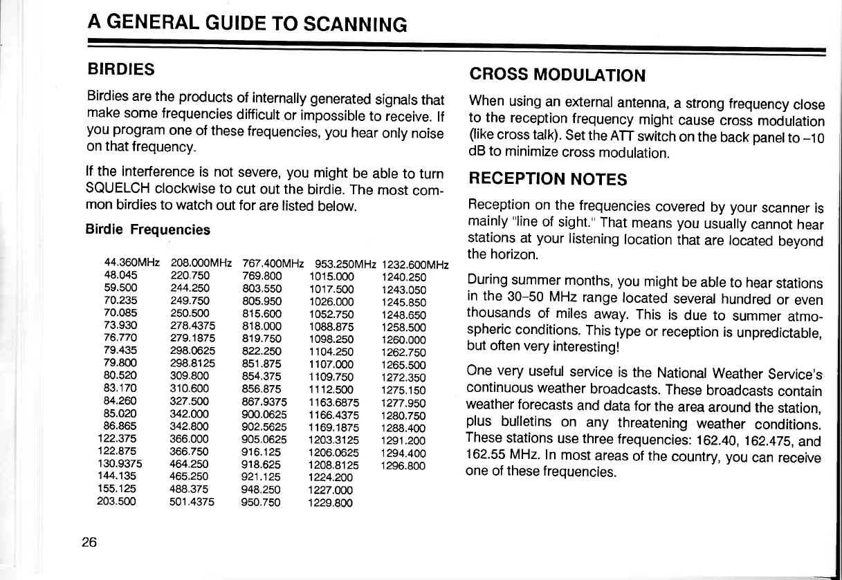
BIRDIES CROSS
MODULATION
Birdies
are the
products
of
internally generated
signals
that When
using
an
external
antenna,
a strong frequency
close
make
some
frequencies
difficult
or impossible
to receive.
lf to the
r""eptior,
frequency
might
cause-cross
modulation
you program
one
of these
frequencies,
you
hear
only noise (like
cross talk).
Set
the
ATT
switch
on the
back
oanelto
-10
on
that
frequency. dB to
minimize
cross
modulation.
lf
the interference
is not
severe,
you
might
be
abte to turn RECEpTION NOTES I
SQUELCH
clockwise to
cut
out
the
birdie. The
most
com- 'tv r
hv I
mon
birdies to watch
out for
are listed
below. Reception
on the
frequencies
covered
by
your
scanner is I
Birdie
Frequencies mainly
"line
of
sight."
That
means you
usually
cannot
hear I
stations
at
your
listening
location
that
are located
beyond I
44.36oMHz
208.000MH2
767.400MH2
953.250MH2
1232.600MH2
the horizon' I
13:333 212.L23
133:333
l3li333
13i3333
During
summer
months,
you
misht
be
abre to h_ear:tations
I
70.23s 24s.7so sos.gso 1026.000 124s.850 ',' the 30-50 MHz range
located
several
hundred
or even I
70.085 25o.5oo 81s.6oo 10s2.750 1248.650 thousands
of miles
away.
This is due to summer
atmo_ |
i3:??3 |i|:.t}iZ !]3
933 1333:313
1333:333
spheric
conditions.
rhis
type
or
reception
is
unpreoiciaore,
I
79.435 298.0625 g22.2so 1104.2s0 1262.7so _ut often
very
interesting! |
79.800 298.8125 851.875 1107.000 1265.500 n^^.,^^,,.^^r,,r ^^_.:^^ !- ^L_ r,-r! |
80.520 3o9.Boo 8s4.375 rroe.zso tili.iso une very
useful
service
is
the
National
Weather
Service's
I
83.170 310.600 8s6.87s 1112.s00
1275.1s0 continuous
weather
broadcasts.
These
broadcasts
contain I
#ff:333
3il:333
336:331!
ll33
?313
1|L|;.?EB
weather
forecasts
and
data for
the
area
around
ll._:jltlo", I
86.86s s42.goo 902.562s
1169.182s
1288.400 ,-'.ts bulletins
on any threatening
weather
conditions. I
122s7s 366.000 905.062s 1203.312s 12s1.200 These
stations
use three
frequencies:
162.40,
162.47s,
and I
13631L
l3?:li3 313:133
1333:3?33
i333:333
162.55
MHz
In
most
areas
of
the
country,
you
can receive
I
144.1s5 465.250 s21.12s pzq.zo6" one
of
these
frequencies. I
155.125 488.375 948.250 1227.OO0 I
203.500 501 .4375 950.7s0 1229.800 |
I
26 1
I
-J

GUIDE
TO THE ACTION BANDS
With
the right frequencies programmed
into
your
scanner,
you
can
monitor
exciting
events.
With
a little
investigation,
you
can find
active frequencies
in
your
community. We
can
give you
some
general
pointers,
and
you
can take it from
there. Please
use
caution
and
common
sense
when
you
hear
an emergency
call. Never
go
to
the
scene of
an emer-
gency
- it
could
be
the
most
dangerous
thing
you
could
ever do.
Find
out if there
is a local
club that monitors
your
community's frequencies.
Perhaps,
a local
electronics
repair
shop
that
works
on
equipment
similar
to
your
scan-
ner
can
give
you
channel frequencies
used by
local
radio
services. A volunteer
police
or fire
employee
can
also be a
good
source
of
this information.
As
a general
rule
on
VHF,
most
activity
concentrates
be-
tween 153.785
and 155.98
MHz
and then
again
from
153.73 to 159.46
MHz.
Here
you
find
local
government,
police,
fire,
and most
such
emergency
seruices.
lf
you
are
near
a railroad
yard
or major
railroad
tracks, look
around
160.0 to 161.9
for
signals.
In
some
larger
cities there
has
been
a move
to the
UHF
bands
for
emergency
services.
Here,
most
of the
activity
is
in
a spread of 453.025-453.95
MHz
and
again between
456.025-459.95
MHz.
In the
UHF band, mobile
units
and control units
associated
with
base and
repeater
units occur in the
overall
spreads
of
456.025-459.95
and
465.025-469.975.
The repeater
units
operate 5
MHz
lower
(that
is,
451.025-454.95
and
460.025-
464.975
MHz) than
the
base units. This means that
if
you
find
an active frequency
inside
one of these
spreads,
you
can
look
5 MHz lower
(or
higher,
as
the
case may
be)
to
find
that radio
seruice.
A new
technology is now
available that
allows
the
use of
the
800 MHz
band for
many
services.
Some
public
safety
agencies
use
trunked
radio,
introduced
to business
sys-
tems in 1979.
With
as many
as
twenty
channels available,
the transmitter
automatically
selects
an unused
channel
each time it is
activated.
Several
agencies
can share
such
a system without
causing
interference.
This
system
can
also be
programmed
to provide
secure
communications
for
selected units, with
unselected
units unable to hear the
message.
Frequencies
in different
bands
are accessible
only at
specific intervals.
However,
the frequencies
that
you
can
store
into
your
scanner's
memory
are
in
5 kHz, 12.5
kHz,
or 50 kHz
steps. Your
scanner
automatically rounds
the
entered
frequency
down to the
nearest valid frequency.
For
example, if
you
try
to enter
a
frequency
of 151.473,
your
scanner accepts this
entry
as
151.470.
27
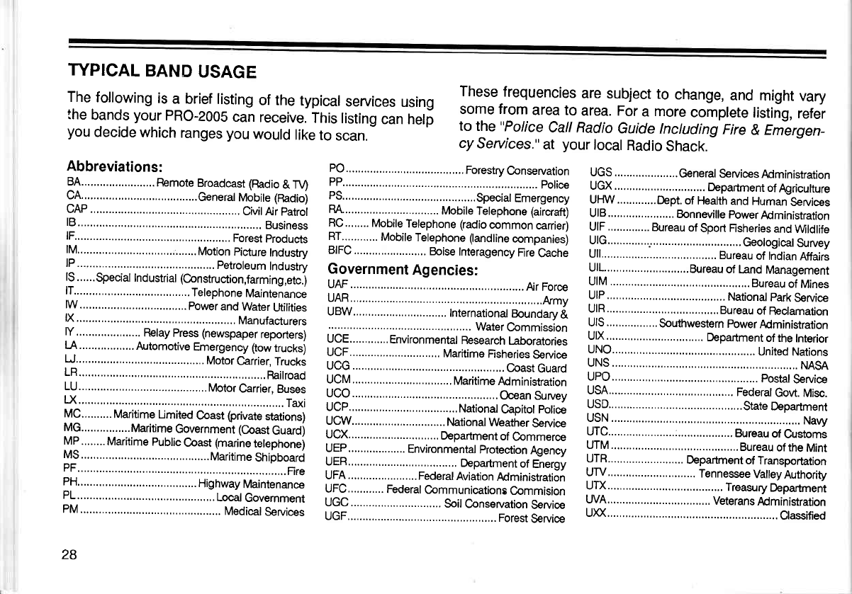
TYPICAL
BAND
USAGE
The
following
is
a brief
listing
of the
typical
seruices
using
the
bands
your
PRO-2005
can
receive.
This
listing
can helf
you
decide
which
ranges you
would
like
to
scan.
These
frequencies
are
subject
to change,
and might
vary
some from
area to area. For
a more
complete
listing,
refer
to the
"Police
Call Radio
Guide
Inctuding
Fire
& Emergen_
cy
Seruices."
at your
local
Radio
Shack.
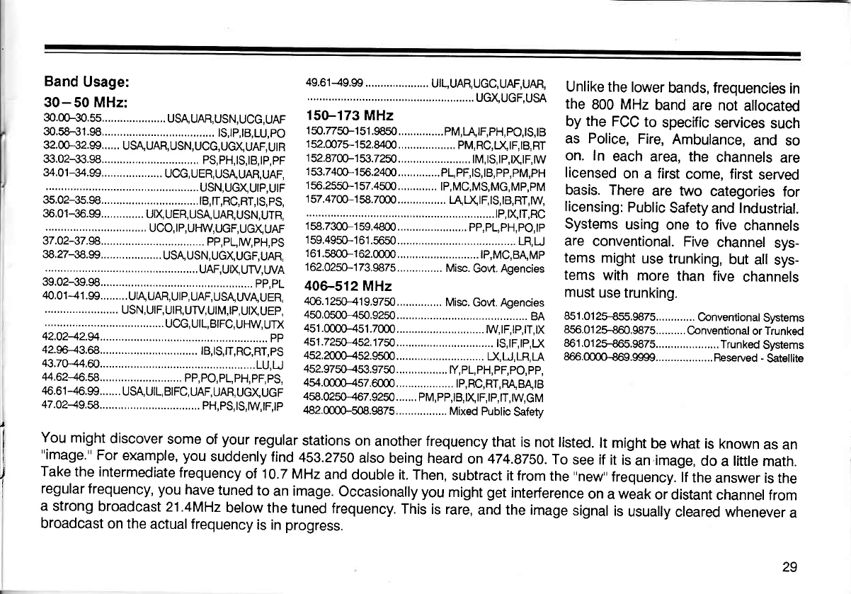
Band
Usage:
30-50 MHz:
30.00-30.s5.....................
usAUAR,
USN,UCG,
UAF
30.58+1.98..... ....... ts,tp,tB,Lu,po
32.00-32.99......
USAUAR,USN,UCG,UcXUAF,UtR
33.02+3.98..... ...
ps,pH,ts,tB,tp,pF
34.01-34,99,,... UCG,UER,USA,UAR,UAF.
..
USN,UGXUIP,UIF
35.02-35.98..... ...
|B,|T,RC,RT,tS,pS,
35.01-35.99..............
UtX
UER, USA,
UAR,USN,UTR,
.........
UCO,IP,UHW,UGF,UGXUAF
37.02-37.98..... .....
PP,PL,WPH,PS
38.27-38.99....................
USA USN,
UGXUcF,UAR,
..UAF,UIXUTV,WA
39.02-39.98..... ...............,.....
pp,pL
40.0 1
-4
1 .99.........
UtA UAR,
U
I
p,
UAF, USA
WA!
U
ER,
USN, UIF,UIR,UTV,UIM,IP,
UX
UEP,
......,,.......
ucc,utL,BtFc,uHW,UTX
42.0242.94.,... .........................
pp
42.96-43.68..... ... tB,ts,|T,Rc,RT,pS
43.70-44.60..... ......................
LU,U
44.62+6.58..... PP,PO,PL,PH,PF,PS,
46,61
-46.99.......
USA, UIL, BIFC,
UAF, UAR,
UGXUGF
47.0249.8..... .... PH,PS,|S,W|F,|P
49.61-49.99..... UIL,UAR,UGC,UAF,UAR,
......
UGXUGF.USA
15G-173
MHz
150.77s0-151.9850...............pM,I-UF,pH,pO,tS,tB
152.0075-152.8400 PM,RC,X|F,|B,RT
152.8700-153.7250........................
tM,tS,tp,txtF,rw
153.7400-156.2400..............pL,pF,tS,t8,pp,pM,pH
1
56.2550-1
57.4500.............
lp, MC,MS,MG,
Mp,pM
157,4700-158.7000 t4LXtF,lS,tB,RT,W
.............
tP,xtT,Rc
158.7300-159.4800.......................
pp,pL,pH,po,tp
159,4950-161.56s0 .....,........
LR,LJ
161.5800-162.0000 ..
|P,MG,BA,MP
1
62.0250-1
73.9875..,............
Misc.
Govt.
Agencies
406-512 MHz
406.
1 250-41
9.9750,..............
Misc.
Govt. Agencies
450.0500-450,9250......,.........................,..........
BA
45r.()()H51.7000 ....tw,tF,tP,tT,tx
451.725p*452j750.................,
tS,tF,tp,D(
4522cnf-<52s500...........................,.
|l,
U, LR, LA
452.9750-453.9750.................
ty,pL,pH,pF,pO,pp,
454.0000-457.6000 tp,Rc,RT,RA,BA"tB
458.0250-467.9250.......
pM,pp,tB,XtF,tp,tT,tw,cM
482.m00-508.9875.................
Mixed Public
Safetv
Unlike the
lower
bands, frequencies
in
the 800 MHz
band
are not
allocated
by
the
FCC
to specific
services
such
as Police,
Fire,
Ambulance,
and
so
on. In each
area, the channels
are
licensed
on
a first
come, first
served
basis.
There
are two categories
for
licensing:
Public
Safety
and Industrial.
Systems
using
one to five
channels
are conventional.
Five
channel
sys-
tems
might
use trunking,
but all
sys-
tems
with
more
than
five
channels
must
use trunking.
851.012H55.987S Conventional
Systems
856.012ffi60.9875..........
Conventional
or Trunked
861.01
2H65.9875.....................
Trunked
Systems
866.@@.9999...................
Fleserved
-
Satellite
I
You
might
discover
some
of
your
regular
stations
on
another frequency
that is
not listed.
lt might
be what
is known
as
an
"image."
For
example,
you
suddenly
find
459.2750
also
being heard
on 474.8750.
To
see if
it iJan.image,
do
a
little
math.
Take
the intermediate
frequency
of 10.7
MHz
and
double it. Then,
subtract it from
the
"new"
frequency.
lf
the
answer is
the
regular
frequency, you
have
tuned
to
an image.
Occasionally
you
might
get
interference
on
a
weak
or distant
channel
from
a strong
broadcast
21.4MHz
below the
tuned
frequency.
This
is rare,
and the
image
signal
is
usually
cleared whenever
a
broadcast
on
the
actualfrequency
is in
progress.
29
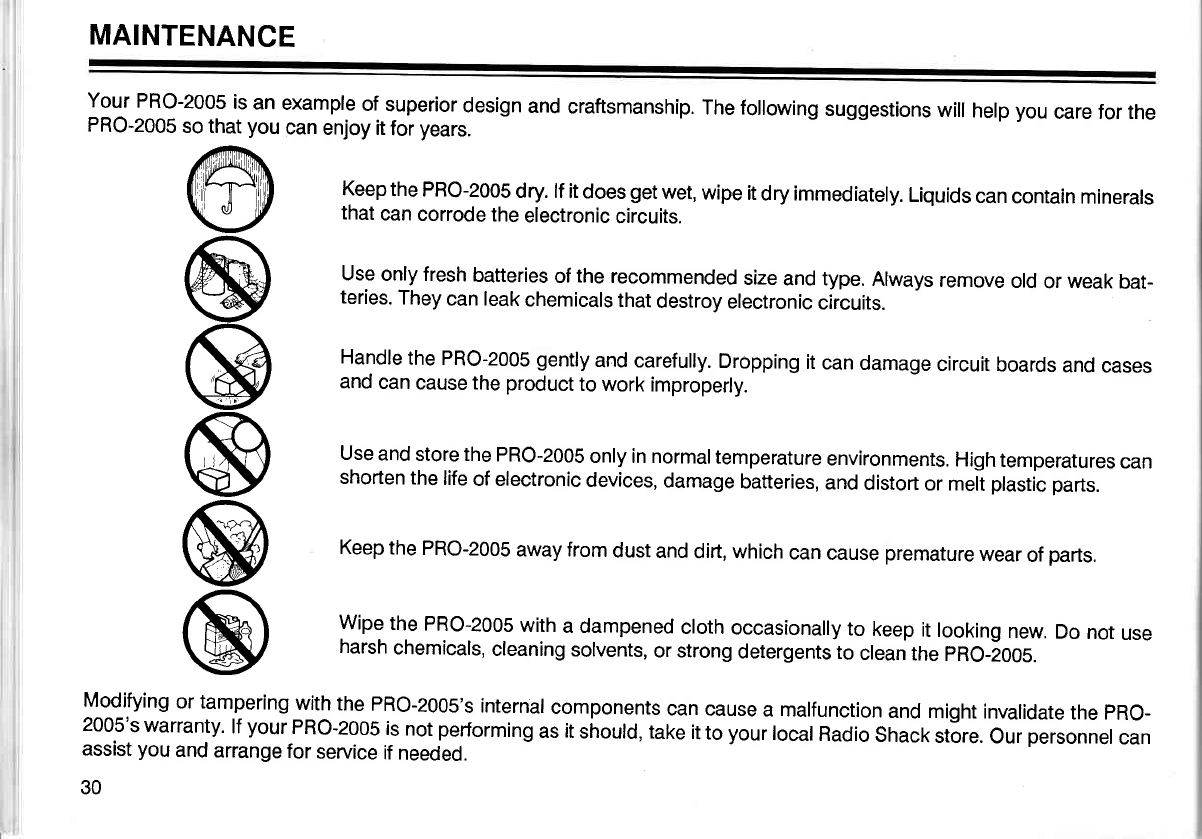
MAINTENANCE
Your
PRO-2005
is an
example
of
superior
design
and
craftsmanship.
The following
suggestions
will
help
you
care for the
PRO-2005
so that
you
can
enjoy it
for
years.
Keep
the
PRO-2005
dry. lf it
does
get
wet,
wipe
it
dry immediately.
Liquids
can
contain
minerals
that
can
corrode
the
electronic
circuits.
Use
only fresh
batteries
of
the
recommended
size
and type.
Always
remove
old
or
weak
bat-
teries.
They
can leak
chemicals
that
destroy
electronic
circuits.
Handle
the PRO-2005 gently
and carefully.
Dropping
it
can
damage
circuit
boards
and
cases
and
can
cause the
product
to work
improperly.
Use
and
store the
PRO-2005
only in normal
temperature
environments.
High
temperatures
can
shorten
the
life
of electronic
devices,
damage
batteries,
and
distort
or meit
plastic
parts.
Keep
the
PRO-2005
away from
dust
and
dirt, which
can
cause
premature
wear
of
parts.
Wipe
the
PRO-2005
with
a dampened
cloth
occasionally
to keep
it
looking
new.
Do
not
use
harsh
chemicals,
cleaning
solvents,
or strong
detergents
to clean
the
pRo-t005.
Modifying
or tampering
with
the
PRO-2005's
internal
components
can
cause
a malfunction
and
might invalidate
the
pRO-
2005's
warranty.
lf
yourPRO-2005
is
not
performing
as
it
si'rould, take
it
to
your
local
Radio
Shack
st6re.
Our
personnel
can
assist
you
and
arrange
for
seruice
if
needed.
30
@
@
@
@
@
@
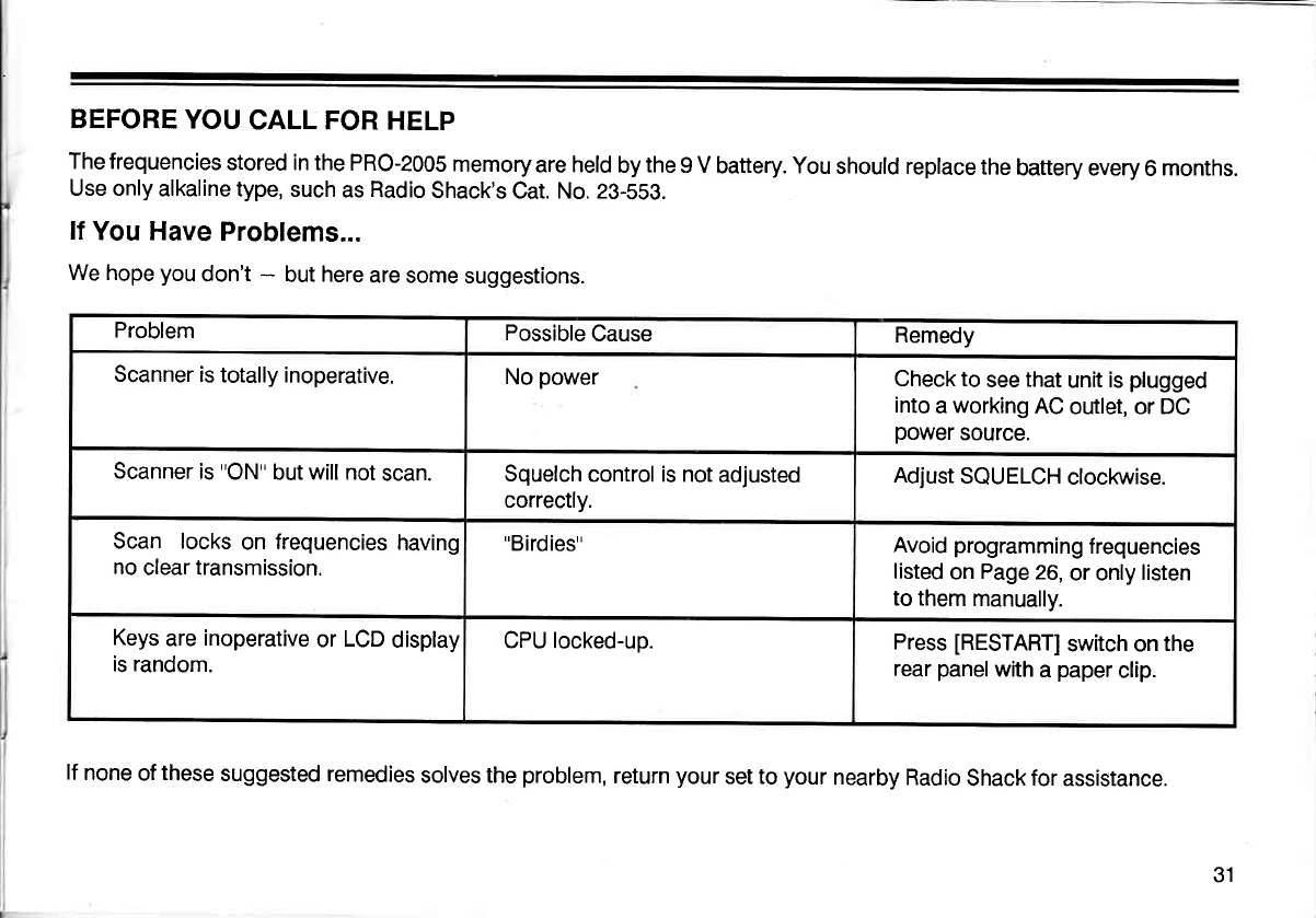
BEFORE
YOU
CALL FOR
HELP
The frequencies
stored in the
PRO-2005
memory
are held
by
the
9 V
battery. You
should replace
the
battery every
6
months.
Use only
alkaline type,
such
as Radio
Shack's
Cat. No. 23-559.
lf
You Have
Problems...
We hope
you
don't
- but
here
are some
suggestions.
Problem Possible
Cause Remedy
Scanner is
totally inoperative. No
power Check to
see
that
unit
is
plugged
into
a
working
AC
outlet, or DC
power
source.
Scanner
is
"ON''
but will not
scan. Squelch
control is not
adjusted
correctly. Adjust
SQUELCH
clockwise.
Scan locks on frequencies
having
no
clear transmission.
"Birdies" Avoid
programming
f requencies
listed
on
Page
26,
or only
listen
to them
manually.
Keys
are
inoperative
or LCD
display
is random. CPU locked-up. Press
[RESTART]
switch on
the
rear
panel
with
a
paper
clip.
lf
none
of
these
suggested remedies
solves the
problem,
return
your
set to
your
nearby Radio
Shack
for
assistance.
31
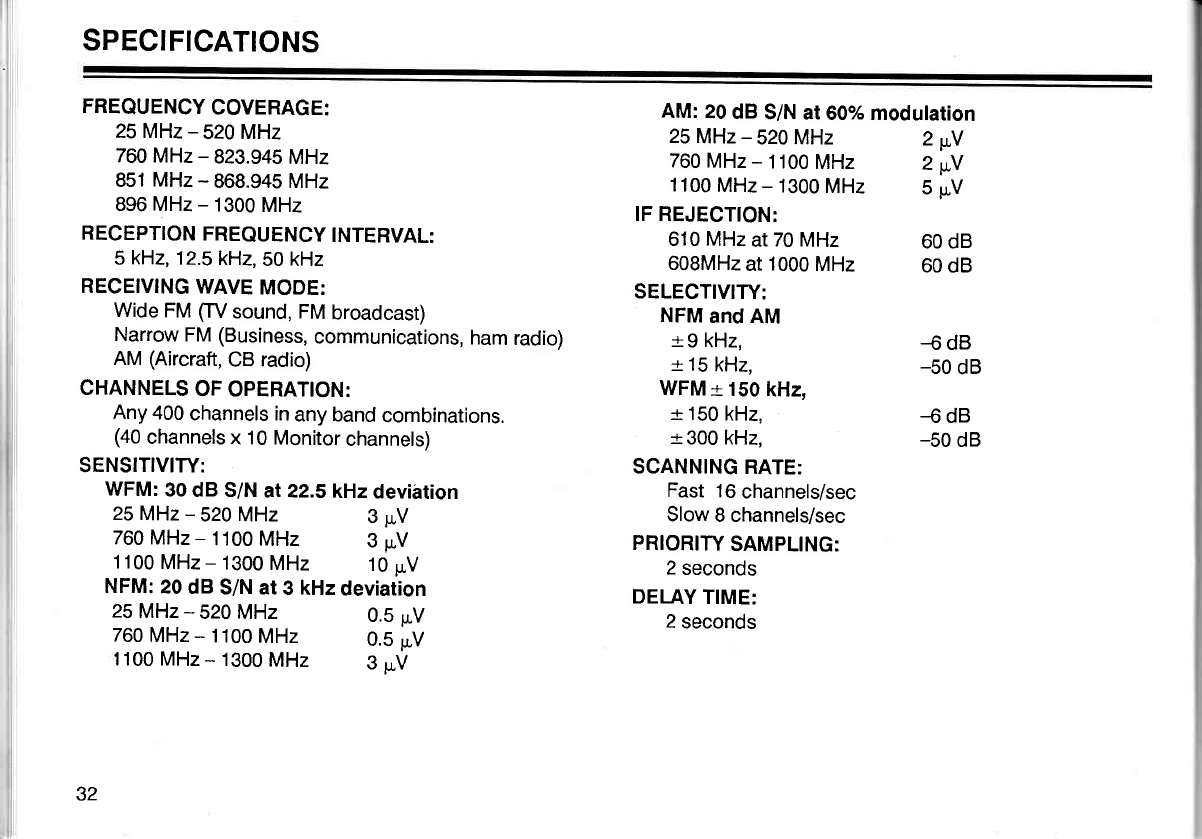
SPECIFICATIONS
FREQUENCY
COVERAGE:
25 MHz
- 520 MHz
760 MHz
- 823.945
MHz
851 MHz
- 868.945 MHz
896 MHz
- 1300
MHz
RECEPTION
FREQUENCY
INTERVAL:
5
kHz,
12.5kH2,50
kHz
RECEIVING
WAVE
MODE:
Wide
FM
ffV sound, FM
broadcast)
Narrow
FM
(Business,
communications,
ham
radio)
AM
(Aircraft,
CB radio)
CHANNELS
OF
OPERATION:
Any
400
channels in
any band
combinations.
(40
channels
x 10 Monitor
channels)
SENSITIVITY:
WFM:
30
dB S/N
at 22.SkHzdevihtion
AM:
20
dB
S/N at60%
modulation
25
MHz
- 520 MHz
760
MHz
- 1100
MHz
IF REJECTION:
610 MHz
at
70
MHz
608MHz
at
1000
MHz
SELECTIVITY:
NFM
and
AM
r-
9 kHz,
+
15
kHz.
WFM
-r
150
kHz,
-r
150
kHz,
r-
300 kHz,
SCANNING
RATE:
Fast
16
channels/sec
Slow
8 channels/sec
PRIORITY
SAMPLING:
2
seconds
DELAY
TIME:
2
seconds
1100
MHz
- 1300
MHz 5
rr,V
2wY
2wY
60 dB
60
dB
-6 dB
-50
dB
-6 dB
-50
dB
25
MHz
- 520 MHz
760 MHz
- 1100
MHz
25
MHz
- 520 MHz
760
MHz
- 1100
MHz
1100
MHz
- 1300
MHz 10
p.V
NFM:
20
dB
S/N at
3 kHz
deviarion
3pv
3pV
0.5
pv
0.5
pv
1100 MHz
- 1300
MHz 3
uV
32
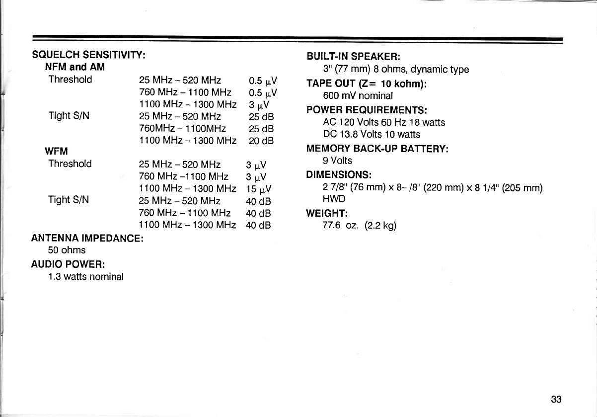
SQUELCH
SENSITIVITY:
NFM
and
AM
Threshold
Tight
S/N
WFM
Threshold
Tight
S/N
ANTENNA
IMPEDANCE:
50 ohms
AUDIO POWER:
1.3
watts nominal
25 MHz- 520 MHz
760 MHz
- 1100
MHz
1100
MHz
- 1300
MHz
25MHz
- 520 MHz
760MHz
- 1100MHz
'1100
MHz
- 1300
MHz
25 MHz
- 520 MHz
760 MHz
-1100
MHz
1100
MHz
- 1300
MHz
25MHz- 520
MHz
760
MHz
- 1100
MHz
1100
MHz
- 1300 MHz
0.5 pV
0.5 pV
3pV
25
dB
25
dB
20
dB
3pV
3pv
15
pV
40
dB
40
dB
40
dB
BUILT-IN
SPEAKER:
3"
(77
mm)
B ohms,
dynamic type
TAPE
OUT
(Z= 10
kohm):
600 mV nominal
PO\'VER REQUIREMENTS:
AC
120 Volts
60
Hz 18 watts
DC
13.8 Volts
10 watts
MEMORY
BACK.UP
BAfiERY:
9 Volts
DIMENSIONS:
2718"
(76
mm)x
U 18"
(220
mm)x
8
1/4'(205
mm)
HWD
WEIGHT:
77.6
oz. (2.2k9)
33

Notes:
34
RADIO
SHACK
LIMITED
WARRANTY
This
product
is warranted
against
defects
fo|I year
trom
date
of
purchase
from
Radro
shack
company-owned
stores
and
authorized
iradio
shack
rraniriiseeiinJ
o""Lrr.
Within
this
period,
we will
repair
it
without
charge
for
parts
and tabor.
Simplv
brlnq
vour
f:dj"^^sl::l-.?l^?:tlt l: p,oof
of
purchase-oare
to
iny Aaoi;Gh";i,i(j|.;'wX|'i"nry
ooes, nor
cover
transportation
costs.
Nor
does it
cover a product
subjected
to misuse
or
accidental
damaoe.
EXqEpr
ns phovroeD
HFRE|N,
RADto
sHAcK
MAKES
No
WARRANT|ES,
ElLlE9s_q!
ryllrED,
INcLUDTNG
wRnRRrurrEs
or naeAciraNineifriV
iNo
FITNESS
FoR A PART|OULAR
puRposE. some siates
do not permir
limitation
or
exclusion
of imptied
warranties;
there{ore,
the
aloresaid
tirltatLniij ,ii!r.frri""iri'rn"v
not
apply
to the
purchaser.
This
warranty gives
you specific legal
rights
and you may also have
other
flghts
which
vary trom state
to state.
We
Service What
We Sell
U.S. PATENT
NOS.
3,794,925
3,801,914
3,961,261
3,962,644
4,027,25'l
4,O92,594
4,123,715
4,245,348
RADIO
SHACK
A Division
of Tandy
Corporation
Fort
Worth,
Texas 76102
12A8 Printed
in
Japan
