Realtek Semiconductor 7305BG13HMCV4 UWB half mini Card User Manual
Realtek Semiconductor Corp. UWB half mini Card Users Manual
Users Manual

Realtek UWB BG13 HMC User Guide_revC.doc
1
All Rights Reserved by Realtek Corp.
Realtek UWB BG13 HMC User Guide
Revision C
Author : Marco Chuang
Date : 2009/02/10
Realtek UWB BG13 HMC User Guide_revC.doc
2
All Rights Reserved by Realtek Corp.
Table of Contents
1. Introduction.................................................................................................................... 3
2. System Description........................................................................................................ 4
2.1. UWB PHY............................................................................................... 5
2.2. UWB MAC.............................................................................................. 5
2.3. SPI Flash................................................................................................... 5
3. Hardware Interfaces....................................................................................................... 6
3.1. PCIe half mini card Interface .............................................................................. 6
4. Document History.......................................................................................................... 7
5. Radiation Exposure Statement....................................................................................... 7
6. Interference Statement ................................................................................................... 7
7. Coordination Requirements ........................................................................................... 8
Realtek UWB BG13 HMC User Guide_revC.doc
3
All Rights Reserved by Realtek Corp.
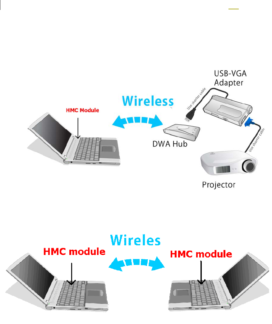
1. Introduction
This document describes the system, operations, and interfaces of the UWB
BG1/3 HMC (half mini card) module. Two main applications are supported
by this module. One is wireless USB application and the other one is WiNet
mode. For WUSB application, the HMC is used as the host controller, and
connect to wired USB device with a wireless DWA hub. WiNet mode is an
IP-based network communication, and link up the networks by UWB module.
WUSB Application
WiNet Application

Realtek UWB BG13 HMC User Guide_revC.doc
4
All Rights Reserved by Realtek Corp.
2. System Description
The UWB BG1 HMC module supports the following functions:
Certified WUSB mode
WiNet mode
Support 53.3M, 80M, 106.7M, 160M, 200M, 320M, 400M, 480Mbps.
Support BG1, BG3 and TFC1~TFC10
The module system mainly consists of two main chips – (i) UWB
PHY(RTU7012), (ii) UWB MAC(RTU7305). A serial flash memory (2Mb)
is required to store proper data/commands for the PHY chip and MAC chip.
To make the system work properly, the Flash should be loaded with proper
content by using the Flash utility provided by Realtek.
The RF performance can also be tested using the test utility provided by
RealTek. Two basic clock frequencies are used in the system – 12MHz for
MAC and 66MHz for PHY. Some more details of the components are shown
in the following sections.
Product Specification
Frequency Band BG1 3168MHz ~ 4752MHz
BG3 6336MHZ ~ 7920MHz
Network Standard WiMedia PHY 1.2 & MAC 1.0
Modulation Mode Multiband OFDM with QPSK, DCM
FEC Coding Rate 1/3, 1/2, 5/8, 3/4 Convolutional Coding, Reed
Solomon Coding
Support Data Rate 8 data rates from 53.3Mbps to 480 Mbps
Interface PCIe half mini card interface
Support Applications Certified WUSB, WiNet

Realtek UWB BG13 HMC User Guide_revC.doc
5
All Rights Reserved by Realtek Corp.
2.1. UWB PHY
This chip integrates the RF and baseband functions of a UWB PHY defined
by the standard. This version of PHY chip is packaged in 48-pin QFN form
factor. The analog/RF section requires 1.5V and 3.3V to operate. The digital
core operates with 1.2V and the I/O voltage can support a range of 3V~3.6V.
2.2. UWB MAC
This MAC chip is also from RealTek which has a standard MPI interface to
communicate with a standard UWB PHY, as well as a high speed USB
interface to connect directly to a PC. This chip requires voltages of 1.2V and
3.3V.
2.3. SPI Flash
This chip is a serial flash memory from Macronix with a capacity of 2Mb. It is
used by the MAC to store the initialization data and command sequence
required by the MAC and PHY on start up. This chip requires 3.3V only.
Realtek UWB BG13 HMC User Guide_revC.doc
6
All Rights Reserved by Realtek Corp.
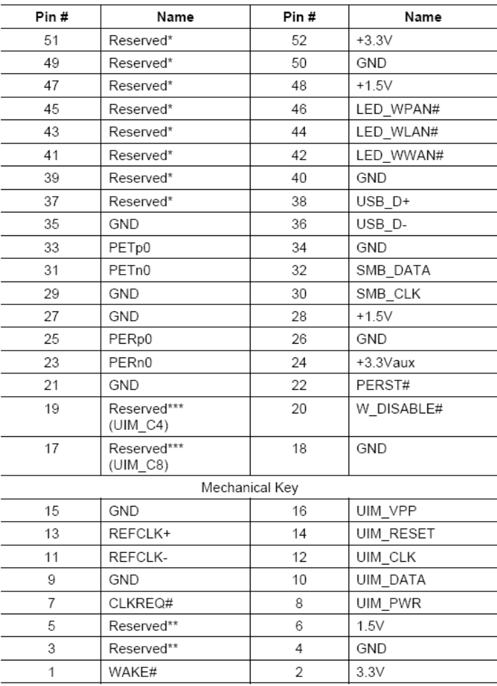
3. Hardware Interfaces
3.1. PCIe half mini card Interface
Table 1 half mini card connector termination assignment

Realtek UWB BG13 HMC User Guide_revC.doc
7
All Rights Reserved by Realtek Corp.
4. Document History
Date Revision Description Author
2008/11/13 A Initial Release Marco Chuang
2009/02/10 C Modify Marco Chuang
5. Radiation Exposure Statement
This equipment complies with FCC radiation exposure limits set forth
for an uncontrolled environment. End users must follow the specific
operating instructions for satisfying RF exposure compliance. To
maintain compliance with FCC RF exposure compliance
requirements, please follow operation instruction as documented in
this manual.
6. Federal Communication Commission Interference
Statement
This equipment has been tested and found to comply with the limits
for a Class B digital device, pursuant to Part 15 of the FCC Rules.
These limits are designed to provide reasonable protection against
harmful interference in a residential installation. This equipment
generates, uses and can radiate radio frequency energy and, if not
installed and used in accordance with the instructions, may cause
harmful interference to radio communications. However, there is no
guarantee that interference will not occur in a particular installation.
If this equipment does cause harmful interference to radio or
television reception, which can be determined by turning the
equipment off and on, the user is encouraged to try to correct the
interference by one of the following measures:
- Reorient or relocate the receiving antenna.
- Increase the separation between the equipment and receiver.
- Connect the equipment into an outlet on a circuit different
from that
to which the receiver is connected.
- Consult the dealer or an experienced radio/TV technician for
help.
Realtek UWB BG13 HMC User Guide_revC.doc
8
All Rights Reserved by Realtek Corp.
CAUTION: Any changes of modifications not expressly approved by the
grantee of this device could void the user’s authority to operate the
equipment.
This transmitter must not be co-located or operating in conjunction with any
other antenna or transmitter.
A UWB device operating under the provisions of this section shall transmit
only when it is sending information to an associated receiver. The UWB
intentional radiator shall cease transmission within 10 seconds unless it
receives an acknowledgement from the associated receiver that its
transmission is being received. An acknowledgement of reception must
continue to be received by the UWB intentional radiator at least every 10
seconds or the UWB device must cease transmitting.
Per FCC regulations, an intentional radiator may only transmit when
communicating with an associated receiver. In end-user applications, this is
achieved through the handshaking, acknowledgements, negotiation of the
communication channel, and other mechanisms those will ensure that the
transmitter is activated only when communicating with a receiver. The
continuous transmitting mode is for compliance and evaluation purpose only
and is not available to the end user.
7. Coordination Requirements
For real application, the transmitter will only be active when
communicating with the specific receiver through handshaking,
acknowledgement and other mechanisms over the wireless channel.