Realtek Semiconductor RTL8192E 802.11b/g/n RTL8192E miniCard User Manual Manual
Realtek Semiconductor Corp. 802.11b/g/n RTL8192E miniCard Manual
Manual

PCI-Express miniCard User’s Manual
Rev. 1.0
03 Dec 2007
Realtek Semiconductor Corp.
No. 2, Innovation Road II, Hsinchu Science Park, Hsinchu 300, Taiwan
Tel.: +886-3-578-0211. Fax: +886-3-577-6047
www.realtek.com.tw
RTL8192E

RTL8192E
User’s Manual
ii Rev.1.0
COPYRIGHT
©2007 Realtek Semiconductor Corp. All rights reserved. No part of this document may be reproduced,
transmitted, transcribed, stored in a retrieval system, or translated into any language in any form or by any
means without the written permission of Realtek Semiconductor Corp.
DISCLAIMER
Realtek provides this document “as is”, without warranty of any kind, neither expressed nor implied,
including, but not limited to, the particular purpose. Realtek may make improvements and/or changes in
this document or in the product described in this document at any time. This document could include
technical inaccuracies or typographical errors.
TRADEMARKS
Realtek is a trademark of Realtek Semiconductor Corporation. Other names mentioned in this document are
trademarks/registered trademarks of their respective owners.
USING THIS DOCUMENT
This document is intended for the software engineer’s reference and provides detailed programming
information.
Though every effort has been made to ensure that this document is current and accurate, more information
may have become available subsequent to the production of this guide. In that event, please contact your
Realtek representative for additional information that may help in the development process.

RTL8192E
User’s Manual
iii Rev.1.0
Table of Contents
1. GENERAL DESCRIPTION................................................................................................................................................4
2. GENERAL FEATURES ......................................................................................................................................................5
3. BLOCK DIAGRAM ............................................................................................................................................................7
4. PRODUCT SPECIFICATIONS..........................................................................................................................................8
4.1. MINI PCI EXPRESS PIN ASSIGNMENT ..............................................................................................................................8
4.2. MECHANICAL..................................................................................................................................................................9
4.3. ENVIRONMENTAL ............................................................................................................................................................9
4.3.1. Operating ...............................................................................................................................................................9
4.3.2. Storage....................................................................................................................................................................9
4.4. FUNCTIONAL SPECIFICATIONS .........................................................................................................................................9
List of Tables
TABLE 1. MINI PCI EXPRESS PIN ASSIGNMENT.............................................................................................................................8
TABLE 2. FUNCTIONAL SPECIFICATIONS........................................................................................................................................9
List of Figures
FIGURE 1. SINGLE BAND 11N APPLICATION DIAGRAM..................................................................................................................7
FIGURE 2. RTL8192E MINICARD MECHANICAL SPECIFICATION ...................................................................................................9

RTL8192E
User’s Manual
4 Rev.1.0
1. General Description
The Realtek RTL8192E miniCard is a highly integrated MIMO wireless LAN (WLAN) used for high speed
wireless local network access. The card is built with a MAC and 1T2R capable baseband chip RTL8192E
with an RF IC RTL8256.
The RTL8192E miniCard implements multiple input, multiple output (MIMO) orthogonal frequency
division multiplexing (OFDM) with 1 transmit and 2 receive paths and is compatible with 802.11n Draft
specification 2.0. Other features include two spatial streams transmission, short guard interval (GI) of
400ns, spatial spreading, and transmission over 20 MHz and 40 MHz bandwidth. Moreover, RTL8192E
provides one spatial stream space-time block code (STBC) to extend the range of transmission. At the
receiver, extended range and good minimum sensitivity is achieved by having receiver diversity up to 2
antennas. As the recipient, the RTL8192E miniCard also supports explicit sounding packet feedback that
helps senders with beamforming capability.
For legacy compatibility, direct sequence spread spectrum (DSSS), complementary code keying (CCK)
and OFDM baseband processing are included to support all 802.11b, and 802.11g data rates. Differential
phase shift keying modulation schemes, DBPSK and DQPSK with data scrambling capability, are available
along with complementary code keying to provide the data rates of 1, 2, 5.5 and 11Mbps with long or short
preamble. The high speed FFT/IFFT paths, combined with BPSK, QPSK, 16QAM, and 64QAM
modulation of the individual subcarriers and rate compatible punctured convolutional coding with coding
rate of 1/2, 2/3, 3/4, and 5/6, provides the maximum data rate of 54 Mbps and 300 Mbps for IEEE 802.11g
and 802.11n MIMO OFDM respectively.
The RTL8192E PCI-E miniCard supports 802.11e for multimedia applications, 802.11i for security, and
802.11n for enhanced MAC protocol efficiency. Using packet aggregation techniques such as A-MPDU
with BA and A-MSDU, protocol efficiency is significantly improved. Power saving mechanisms such as
U-APSD, APSD, and MIMO power saving reduces the power wasted during idle time, and compensates for
the extra power required to transmit MIMO OFDM. The RTL8192E PCI-E miniCard provides simple
legacy and 20Mhz/40Mhz co-existence mechanisms to ensure backward and network compatibility.

RTL8192E
User’s Manual
5 Rev.1.0
2. General Features
General
• Operate at ISM frequency bands (2.4GHz)
• IEEE standards support: IEEE 802.11b, 802.11g, draft 802.11n
• Mini PCI Express interface
• Enterprise level security which can apply WPA2 certification
• 1 transmitter and 2 receivers allow data rates supporting up to 300 Mbps downstream and 150 Mbps
upstream PHY rates.
• Full-featured software utility for easy configuration and management
• Power savings features and low power consumptions for mobile powered applications
• Rohs compliance
Host Interface
• Complies with PCI Express™ Base Specification Revision 1.1
Standards supported
• IEEE 802.11b/g/n compatible WLAN
• 802.11e QoS Enhancement (WMM, WMM-SA Client mode)
• 802.11i (WPA, WPA2). Open, shared key, and pair-wise key authentication services.
• Cisco Compatible Extensions (CCX4)CCX
MAC Features
• Frame aggregation increase MAC efficiency (A-MSDU, A-MPDU)
• Low latency Immediate High-Throughput Block Acknowledgement (HT-BA)
• Long NAV for media reservation with CF-End for NAV release
• PHY-level spoofing to enhance legacy compatibility
• MIMO power saving mechanism
• Channel management and co-existence
• Multiple BSSID feature allowing RTL8192E to assume multiple MAC identity when used as wireless
bridge
• Supports Wake-On-WLAN via Magic Packet and wake-up frame
• TXOP SIFS bursting guarantees multimedia bandwidth.

RTL8192E
User’s Manual
6 Rev.1.0
PHY Features
• IEEE 802.11n draft 2.0 MIMO OFDM
- 1 transmitter and 2 receivers (1T2R).
- 20MHz and 40MHz bandwidth transmission.
- Short Guard Interval (400ns).
- 1 spatial stream STBC transmission for extended coverage.
- Sounding packet.
• DSSS with DBPSK and DQPSK, CCK modulations with long and short preamble.
• OFDM with BPSK, QPSK, 16QAM, 64QAM, and 256QAM modulations. Convolutional coding rate:
1/2, 2/3, 3/4, and 5/6.
• Maximum data rate 54Mbps in 802.11g and 300Mbps in 802.11n.
• OFDM receive diversity with MRC using up to 4 receive paths. Switch diversity used for DSSS/CCK.
• Hardware antenna diversity.
• Selectable digital transmit and receiver FIR filters
• Programmable scaling in transmitter and receiver to trade quantization noise against increasing
probability of clipping.
• Fast receiver automatic gain control (AGC).
RTL8192E
User’s Manual
7 Rev.1.0
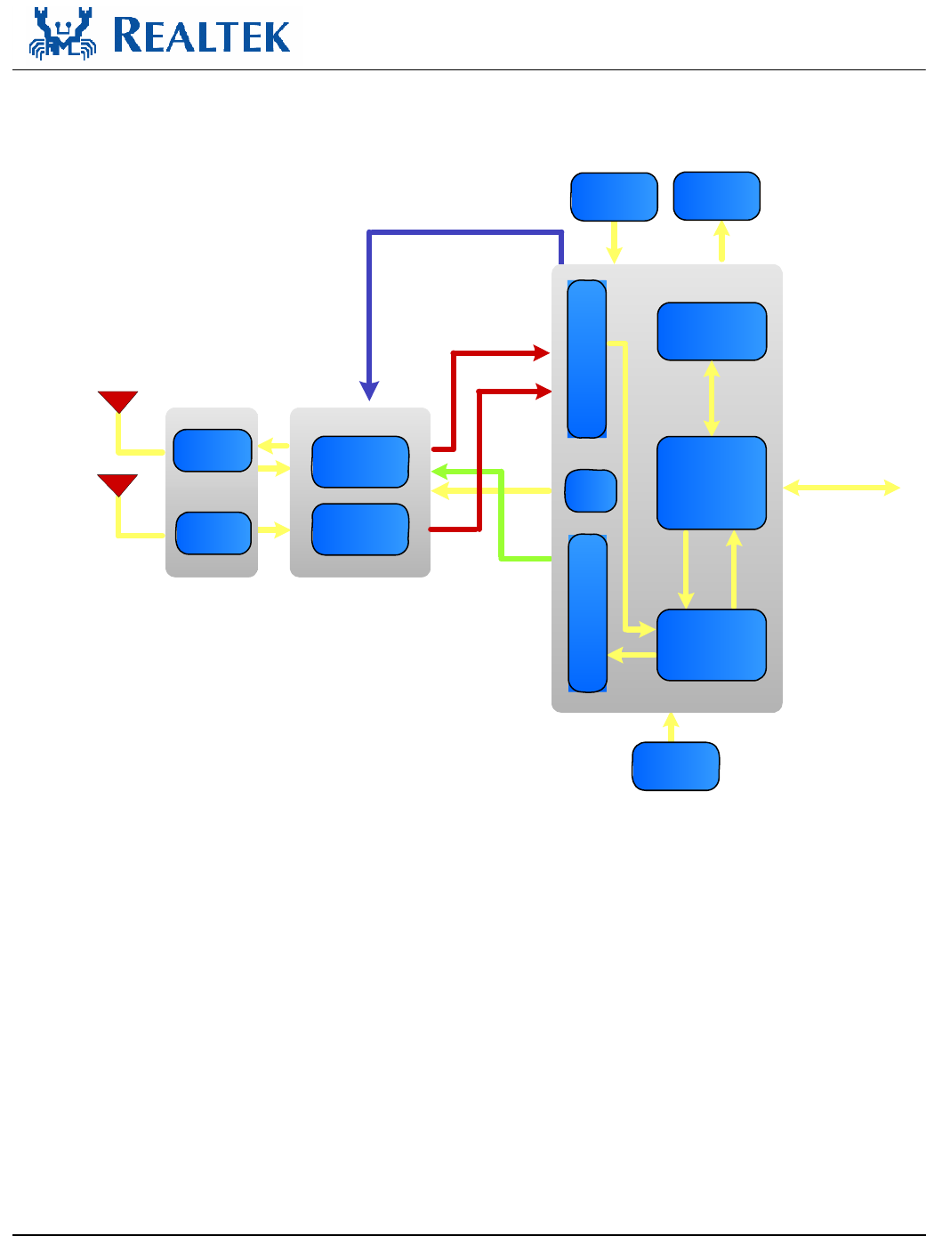
3. Block Diagram
External LEDs
EEPROM
ADC
Ext Interface
PCI Express
Host
Interface
2.4G
Transceiver B
2.4G
Transceiver A
RX I/Q
T/Rx Matching
Circuit
Rx Matching
Circuit
Antenna
A
Antenna
B
RTL8256
RTL8192E
MAC
Configuration
Control and
Memory
Baseband
(PHY)
Control
DAC
40 MHz
Clock
40M Crystal
TX I/Q
Figure 1. Single Band 11n Application Diagram
RTL8192E
User’s Manual
8 Rev.1.0
4. Product specifications
4.1.
Mini PCI Express Pin Assignment
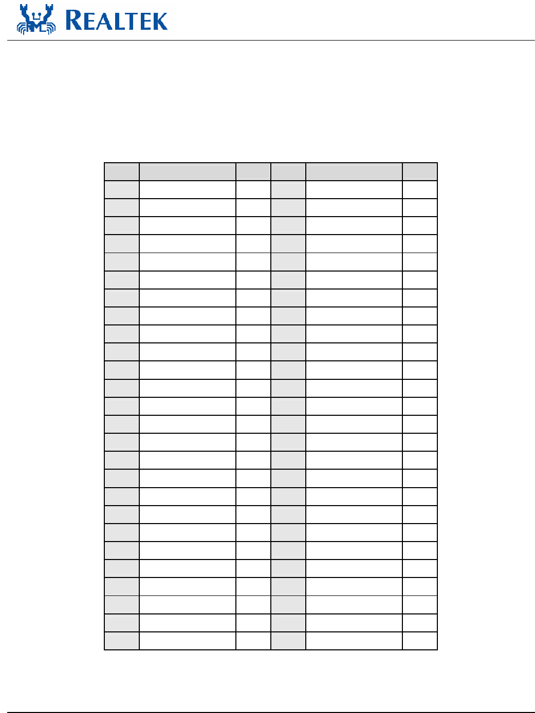
Table 1. Mini PCI Express Pin Assignment
PIN# Pin Name PIN# Pin Name
1 WAKE# YES 2 3.3V YES
3 RESERVED NC 4 GND YES
5 RESERVED NC 6 1.5V NC
7 CLKREQ# YES 8 RESERVED NC
9 GND YES 10 RESERVED NC
11 REFCLK+ YES 12 RESERVED NC
13 REFCLK- YES 14 RESERVED NC
15 GND YES 16 RESERVED NC
17 RESERVED NC 18 GND YES
19 RESERVED NC 20 W_DISABLE# YES
21 GND YES 22 PERST# YES
23 PERn0 YES 24 +3.3Vaux YES
25 PERp0 YES 26 GND YES
27 GND YES 28 +1.5V NC
29 GND YES 30 SMB_CLK NC
31 PETn0 YES 32 SMB_DATA NC
33 PETp0 YES 34 GND YES
35 GND YES 36 USB_D- NC
37 RESERVED NC 38 USB_D+ NC
39 RESERVED NC 40 GND YES
41 RESERVED NC 42 LED_WWAN# NC
43 RESERVED NC 44 LED_WLAN# YES
45 RESERVED NC 46 LED_WPAN# NC
47 RESERVED NC 48 +1.5V NC
49 RESERVED NC 50 GND YES
51 RESERVED NC 52 +3.3V YES
RTL8192E
User’s Manual
9 Rev.1.0
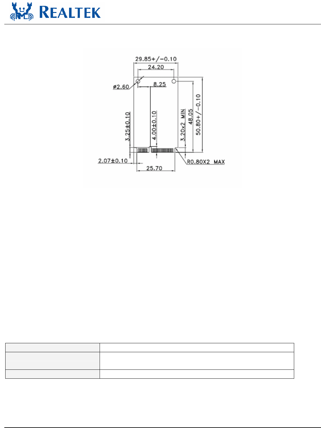
4.2.
Mechanical
Figure 2. RTL8192E miniCard Mechanical Specification
4.3.
Environmental
4.3.1. Operating
Operating Temperature: 0 to 70 °C
Relative Humidity: 5-90% (non-condensing)
4.3.2. Storage
Temperature: -55 to 125 °C
Relevant Humidity: 5-95% (non-condensing
4.4.
Functional Specifications
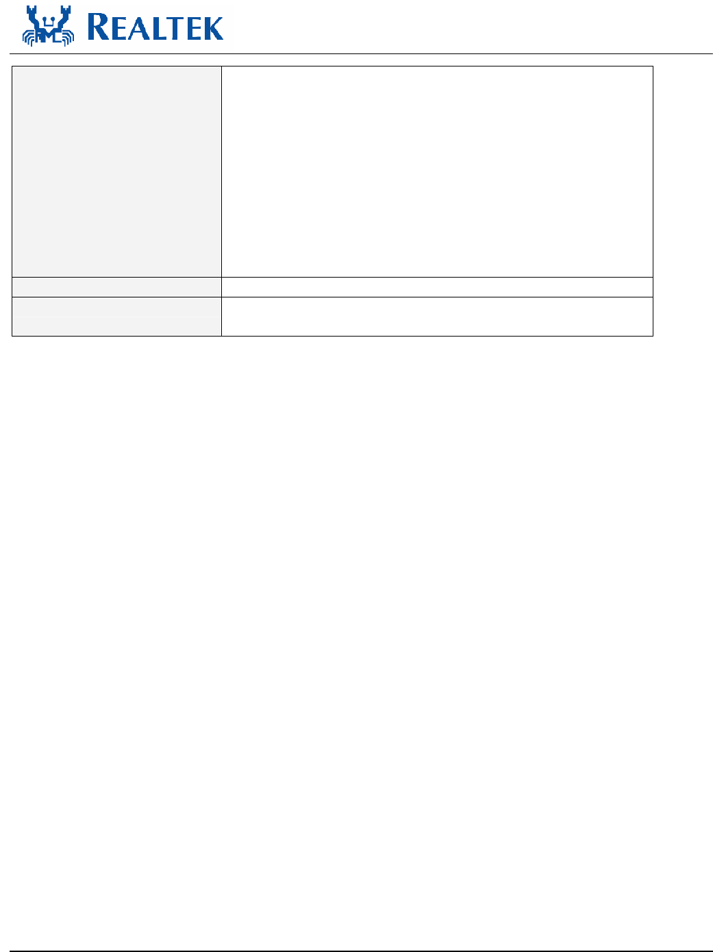
Table 2. Functional Specifications
POWER SUPPLY DC 3.2~3.5V from host equipment
MODULATION TYPE CCK, DQPSK, DBPSK for DSSS
64QAM, 16QAM, QPSK, BPSK for OFDM
MODULATION Technology DSSS, OFDM
RTL8192E
User’s Manual
10 Rev.1.0
Transfer rate 802.11b: 11 / 5.5 / 2 / 1Mbps
802.11g: 54 / 48 / 36 / 24 / 18 / 12 / 9 / 6Mbps
Draft 802.11n (20MHz, 800ns GI): 130 / 117 / 104 / 78 / 65 / 58.5
/ 52 / 39 / 26 / 19.5 / 13 / 6.5Mbps
Draft 802.11n (40MHz, 800ns GI): 270 / 243 / 216 / 162 /135 /
121.5 / 108 / 81 / 54 / 40.5 / 27 / 13.5Mbps
Draft 802.11n (20MHz, 400ns GI): 144.444 / 130 / 115.556 /
86.667 / 72.2 / 65 / 57.8 / 57.778 / 43.333 / 43.3 / 28.9 / 28.889 /
21.7 / 14.444 / 14.4 / 7.2Mbps
Draft 802.11n (40MHz, 400ns GI): 300 / 270 / 240 / 180 / 150 /
135 / 120 / 90 / 60 / 45 / 30 / 15Mbps
FREQUENCY Range 2400MHz ~ 2483.5MHz
NUMBER OF CHANNEL 11 for 802.11b, 802.11g, draft 802.11n (20MHz)
7 for draft 802.11n (40MHz)
Federal Communication Commission Interference Statement
This equipment has been tested and found to comply with the limits for a Class B digital device, pursuant to Part 15 of the FCC
Rules. These limits are designed to provide reasonable protection against harmful interference in a residential installation. This
equipment generates, uses and can radiate radio frequency energy and, if not installed and used in accordance with the
instructions, may cause harmful interference to radio communications. However, there is no guarantee that interference will not
occur in a particular installation. If this equipment does cause harmful interference to radio or television reception, which can be
determined by turning the equipment off and on, the user is encouraged to try to correct the interference by one of the following
measures:
- Reorient or relocate the receiving antenna.
- Increase the separation between the equipment and receiver.
- Connect the equipment into an outlet on a circuit different from that
to which the receiver is connected.
- Consult the dealer or an experienced radio/TV technician for help.
This device complies with Part 15 of the FCC Rules. Operation is subject to the following two conditions: (1) This device may
not cause harmful interference, and (2) this device must accept any interference received, including interference that may cause
undesired operation.
FCC Caution: Any changes or modifications not expressly approved by the party responsible for compliance could void the
user's authority to operate this equipment.
IMPORTANT NOTE:
FCC Radiation Exposure Statement:
This equipment complies with FCC radiation exposure limits set forth for an uncontrolled environment. This equipment should
be installed and operated with minimum distance 20cm between the radiator & your body.
This transmitter must not be co-located or operating in conjunction with any other antenna or transmitter.
IEEE 802.11b or 802.11g operation of this product in the U.S.A. is firmware-limited to channels 1 through 11.
This device is intended only for OEM integrators under the following conditions:
The antenna must be installed such that 20 cm is maintained between the antenna and users, and
The transmitter module may not be co-located with any other transmitter or antenna,
For all products market in US, OEM has to limit the operation channels in CH1 to CH11 for 2.4G band by supplied firmware
programming tool. OEM shall not supply any tool or info to the end-user regarding to Regulatory Domain change.

RTL8192E
User’s Manual
11 Rev.1.0
As long as 3 conditions above are met, further transmitter test will not be required. However, the OEM integrator is still
responsible for testing their end-product for any additional compliance requirements required with this module installed (for
example, digital device emissions, PC peripheral requirements, etc.).
IMPORTANT NOTE: In the event that these conditions can not be met (for example certain laptop configurations or co-location
with another transmitter), then the FCC authorization is no longer considered valid and the FCC ID can not be used on the final
product. In these circumstances, the OEM integrator will be responsible for re-evaluating the end product (including the
transmitter) and obtaining a separate FCC authorization.
End Product Labeling
This transmitter module is authorized only for use in device where the antenna may be installed such that 20 cm may be
maintained between the antenna and users. The final end product must be labeled in a visible area with the following: “Contains
FCC ID: TX2-RTL8192E”.
Manual Information To the End User
The OEM integrator has to be aware not to provide information to the end user regarding how to install or remove this RF module
in the user’s manual of the end product which integrates this module.
The end user manual shall include all required regulatory information/warning as show in this manual.
Industry Canada Statement
This device complies with RSS-210 of the Industry Canada Rules. Operation is subject to the following two conditions:
1) this device may not cause interference and
2) this device must accept any interference, including interference that may cause undesired operation of the device
This device has been designed to operate with an antenna having a maximum gain of 3.95 dBi.
Antenna having a higher gain is strictly prohibited per regulations of Industry Canada. The required antenna
impedance is 50 ohms.
To reduce potential radio interference to other users, the antenna type and its gain should be so chosen that the EIRP is not more
than required for successful communication.
IMPORTANT NOTE:
IC Radiation Exposure Statement:
This equipment complies with IC radiation exposure limits set forth for an uncontrolled environment. This equipment should be
installed and operated with minimum distance 20cm between the radiator & your body.
Realtek Semiconductor Corp.
Headquarters
No. 2, Innovation Road II, Hsinchu Science Park,
Hsinchu, 300, Taiwan, R.O.C.
Tel: 886-3-5780211 Fax: 886-3-5776047
www.realtek.com.tw