Realtek Semiconductor RTL8710BN 802.11 bgn Wireless module User Manual RTL8710BN R OK
Realtek Semiconductor Corp. 802.11 bgn Wireless module RTL8710BN R OK
Users Manual

RTL8710BN
BuildandDebugEnvironmentSetup–IAR
ThisdocumentillustrateshowtobuildRealteklowpowerWi‐FisoftwareunderIARSDK
environment.

RTL8710BN
2017‐12‐262
TableofContents
1.Introduction .................................................................................................................................3
2.HowtogetIAR .............................................................................................................................3
3.Ameba‐ZHardwareConfiguration ...............................................................................................3
4.Howtobuildanddownloadcode ................................................................................................4
4.1IARbuild .................................................................................................................................4
4.2IARdownload .........................................................................................................................8
4.3IARdebug .............................................................................................................................10
5.Imagetooldownload .................................................................................................................13
6.Howtouseperipheralsamplecode ..........................................................................................14
7.Warning......................................................................................................................................15
.
RTL8710BN
2017‐12‐263
1.Introduction
ThisdocumentillustrateshowtobuildRealteklowpowerWi‐FisoftwareunderIARSDK
environment.
2.HowtogetIAR
IARprovidesanIDEenvironmentforcodebuilding,downloading,anddebugging.Pleasecheck
“IAREmbeddedWorkbench”onhttp://www.iar.com/,andtrailversionisavailable.
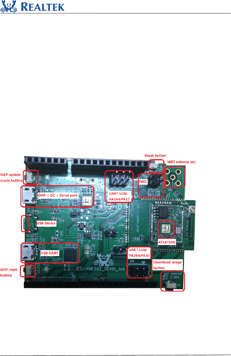
3.Ameba‐ZHardwareConfiguration
HardwareblockdiagramisshowninFigure3‐1Hardwareblockdiagram.TheblockUSBUARTis
usedtosupplypowerandcatchlogs,UARTbaudis115200.SWDmeansJ‐LinkSWDinterface,
whenitisconnectedtoJ‐LinkAdaptercorrectly,youcandownloadimagestoAmeba‐ZfromIAR
flashdownloader.ResetbuttonisusedtoresetAmeba‐ZtorunfirmwareafterIARcompletes
downloading.
Figure3‐1Hardwareblockdiagram
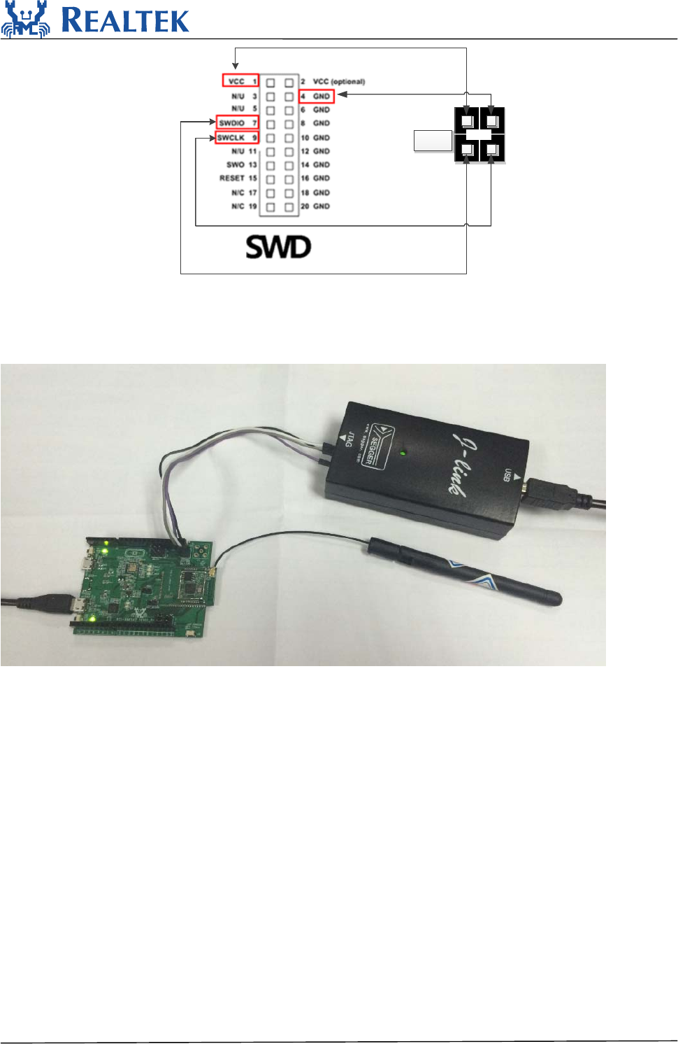
TheDupontLinediagrambetweenJ‐LinkAdapterandAmeba‐ZSWDisasfollows:
RTL8710BN
2017‐12‐264
3.3VGND
DATACLK
SWD
Figure3‐2J‐LinkSWDconnection
PleasenoticethatDAPchipisnotweldingontheAmeba‐ZdemoboardandsoDAPfunctionisnot
enabledwhichmeansMBEDudiskcopyisdisabled.
Physicalconnectionasshownbelow:
Figure3‐3Physicalconnection
4.Howtobuildanddownloadcode
PleasemakesureUSBUARTisconnectedtoPCwithUSBlineandSWDisconnecttoJ‐LinkAdapter
withDupontLinebeforedownloadcode.
4.1IARbuild
Step1:OpenIARWorkbench
Step2:Toopenproject,clickFileOpenWorkspace
RTL8710BN
2017‐12‐265
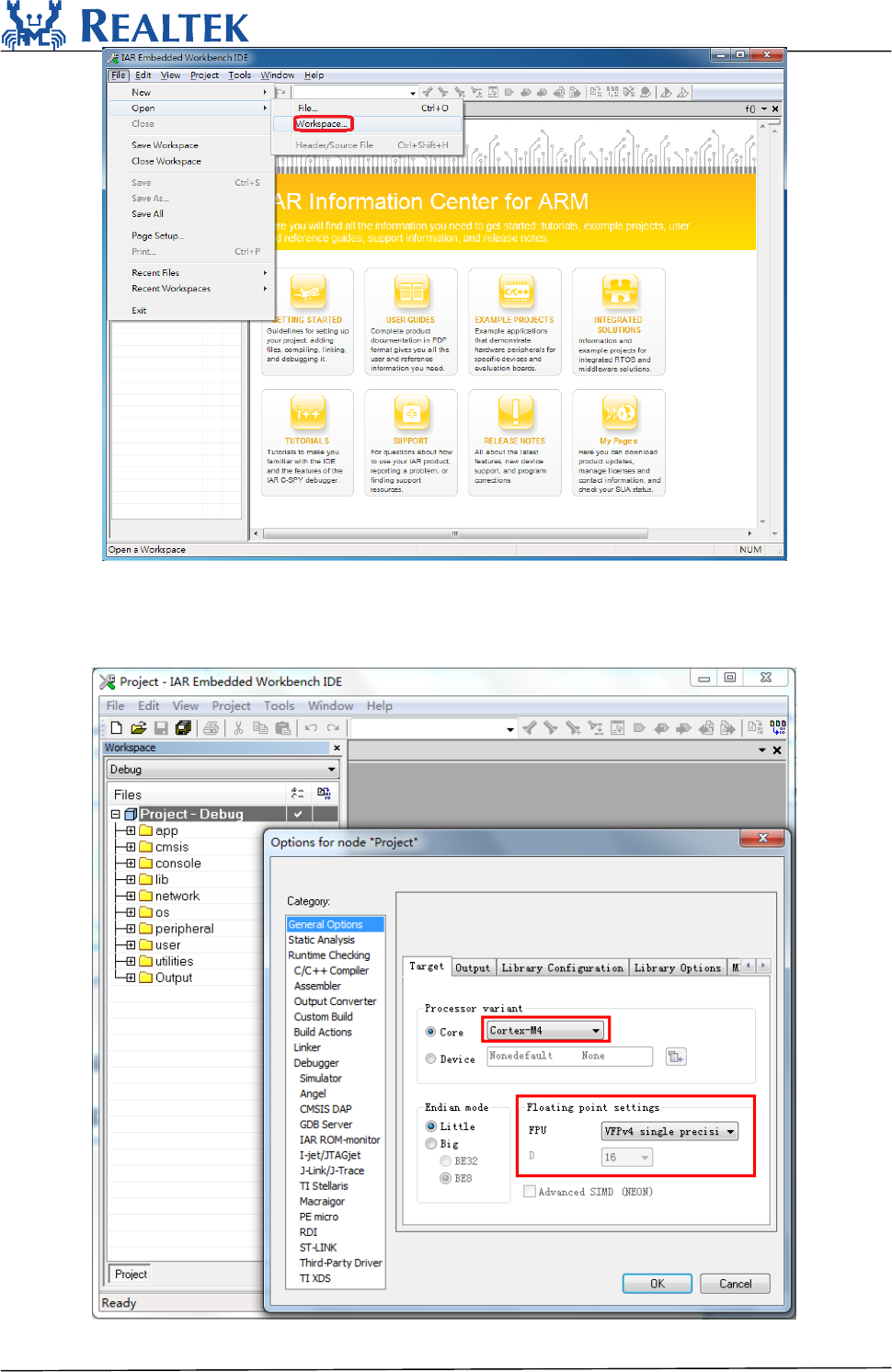
Step3:SelectProject.ewwinproject\realtek_amebaz_va0_example\EWARM‐RELEASE
ClickProjectOptions,GeneralOptions‐>Target‐>ProcessorVariant‐>Core,makesureyouhave
chosenCortex‐M4f.IfyourIARnotsupportthiscore,PleasechooseCortex‐M4andFloatingpoint
settings‐>FPUissetto“VFPv4singleprecision”.
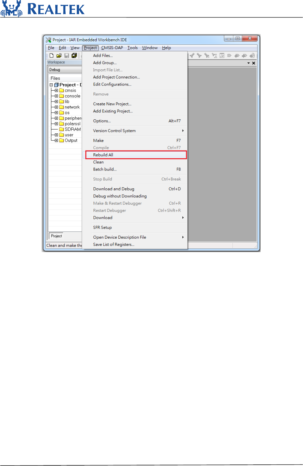
Step4:Tobuildproject,clickProjectRebuildAll
RTL8710BN
2017‐12‐266
Thenyouwillgetboot_all.binandimage2_all_ota1.binin
project\realtek_amebaz_va0_example\EWARM‐RELEASE\Debug\Exe.
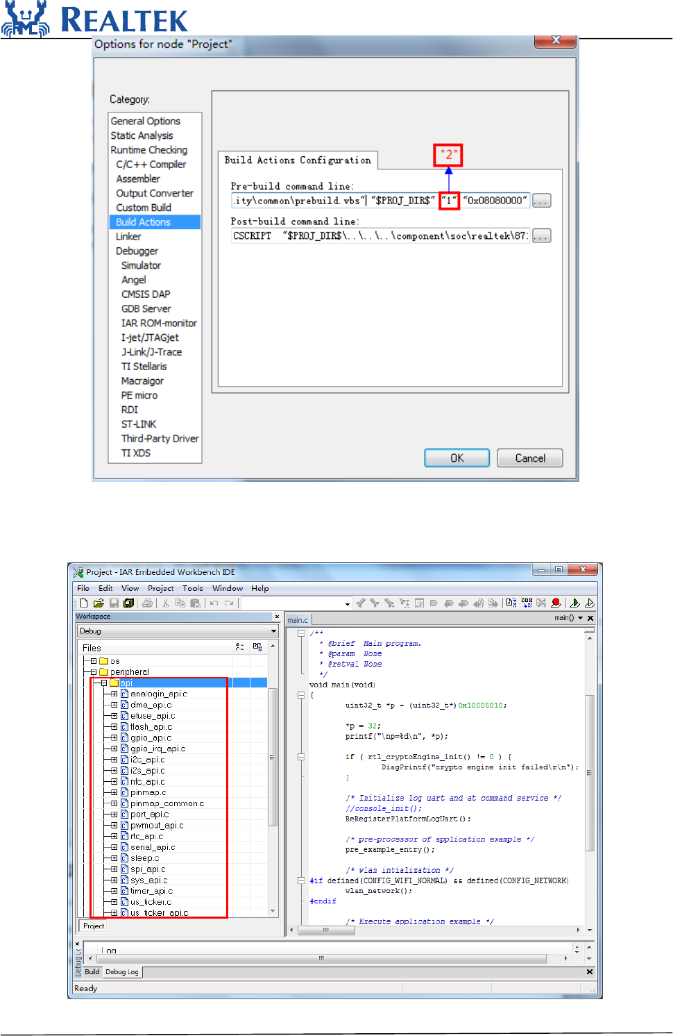
Step5:Tobuildimage2_all_ota2.binforOTA,clickProject‐>Options‐>BuildActions‐>BuildActions
Configuration‐>Pre‐buildcommandline,changethesecondaryparameter“1”to“2”shownas
follows,thenClickOKandmakeproject“RebuildAll”.
Thenyouwillgetimage2_all_ota2.bininproject\realtek_amebaz_va0_example\EWARM‐RELEASE
\Debug\Exe.
RTL8710BN
2017‐12‐267
Bytheway,thembedAPIsincludeCfilesandHeaderfilesusedbyAmeba‐Zislocatedin
component\soc\realtek\8711b\mbed\.Itwillalsobemergedtocomponent\common\mbed\in
nextversion.NowifyouuseAmeba‐1,pleasechoosefilesfromcomponent\common\mbed\andif
youuseAmeba‐Z,pleasechoosefilesfromcomponent\soc\realtek\8711b\mbed\.
RTL8710BN
2017‐12‐268
4.2IARdownload
TheAmeba‐ZdemoboardonlysupportsJLINKSWDdownloadanddebug.
PleasenotethatifyouwantuseIARdownloadimagetodebug,pleasesetthesecondary
parameterofprebuild.batto“1”andbuild.
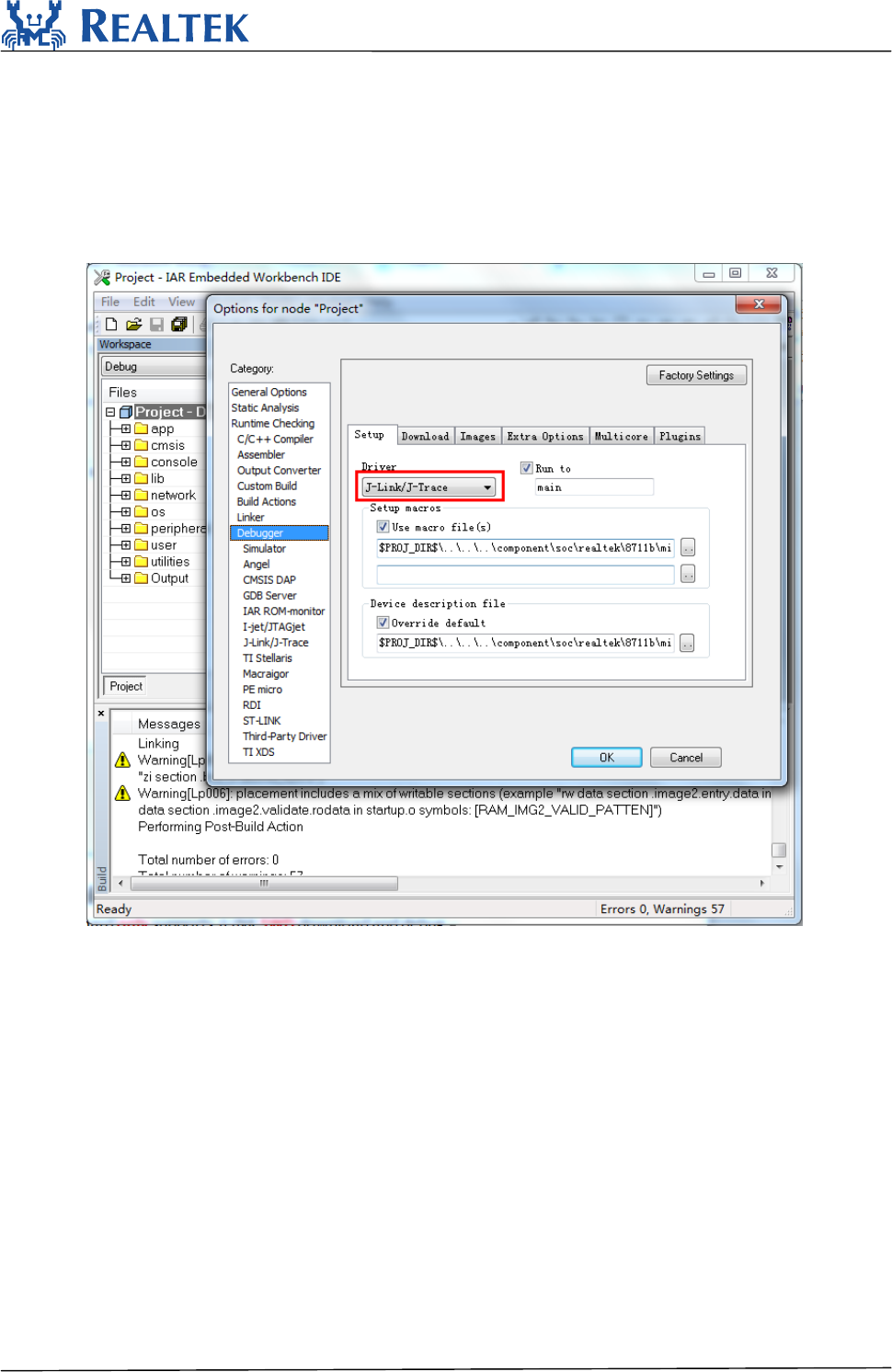
Step1:PleasecheckJ‐linkdebuggerissettingcorrect.Click
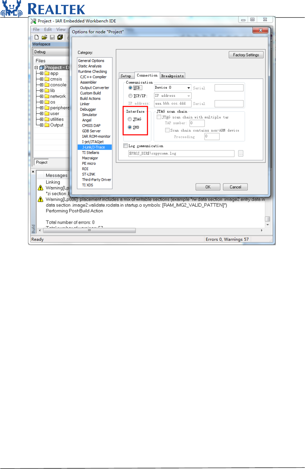
Project‐>Options‐>Debugger‐>Setup‐>Driver,andchoose“J‐Link/J‐Trace”.ThenclickDebugger‐>
J‐Link/J‐Trace‐>Connection‐>Interfaceandchoose“SWD”.
RTL8710BN
2017‐12‐269
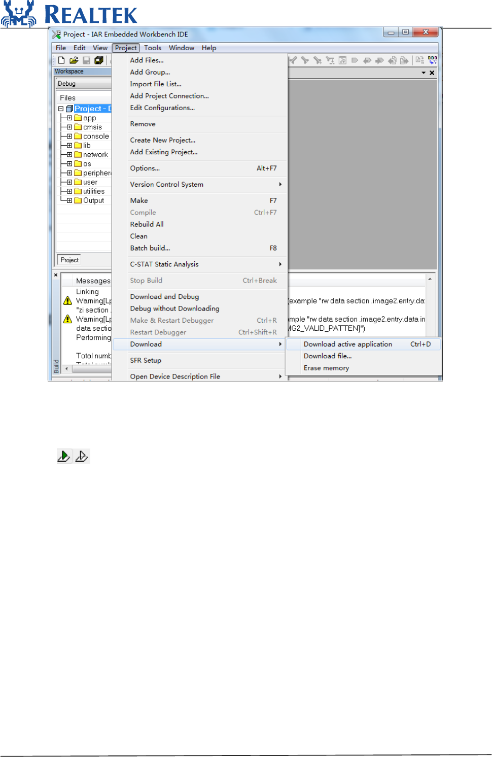
Step2:Todownloadcode,clickProject‐>Download‐>Downloadactiveapplication.
RTL8710BN
2017‐12‐2610
Afterfirmwaredownload,clickResetbuttontorebootthesystem.
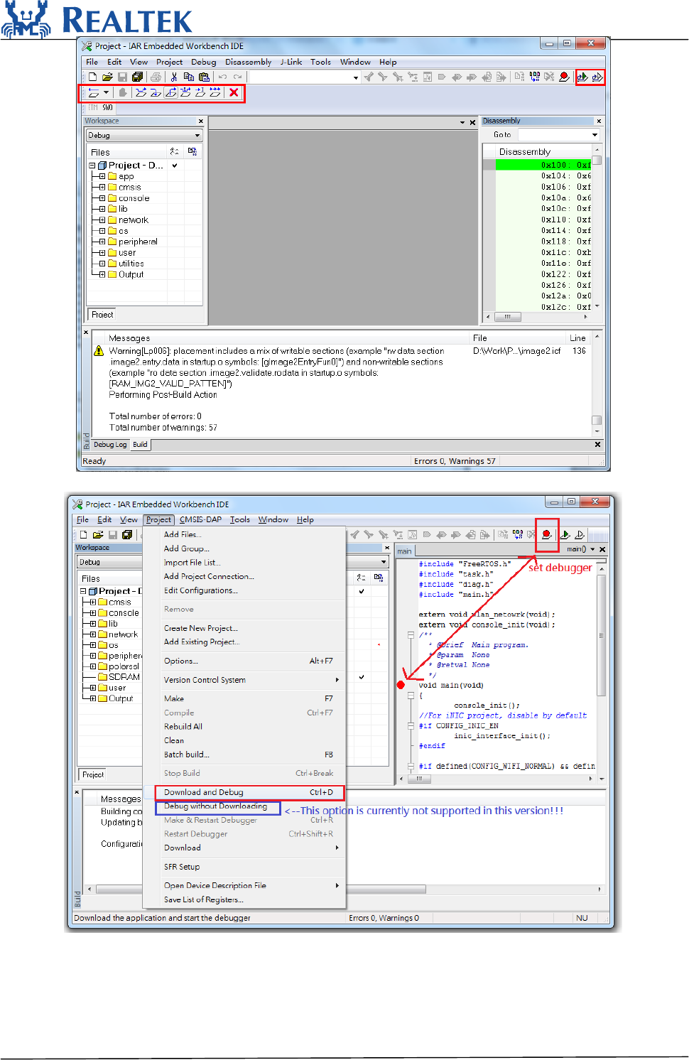
4.3IARdebug
Todebugortracecodestepbystep,clickProjectDownloadandDebugorpressoneofthetwo
buttons intheIARmenu.
Upperleftcornerofthetoolbarshowsstepbysteptrackingtools.
RTL8710BN
2017‐12‐2611
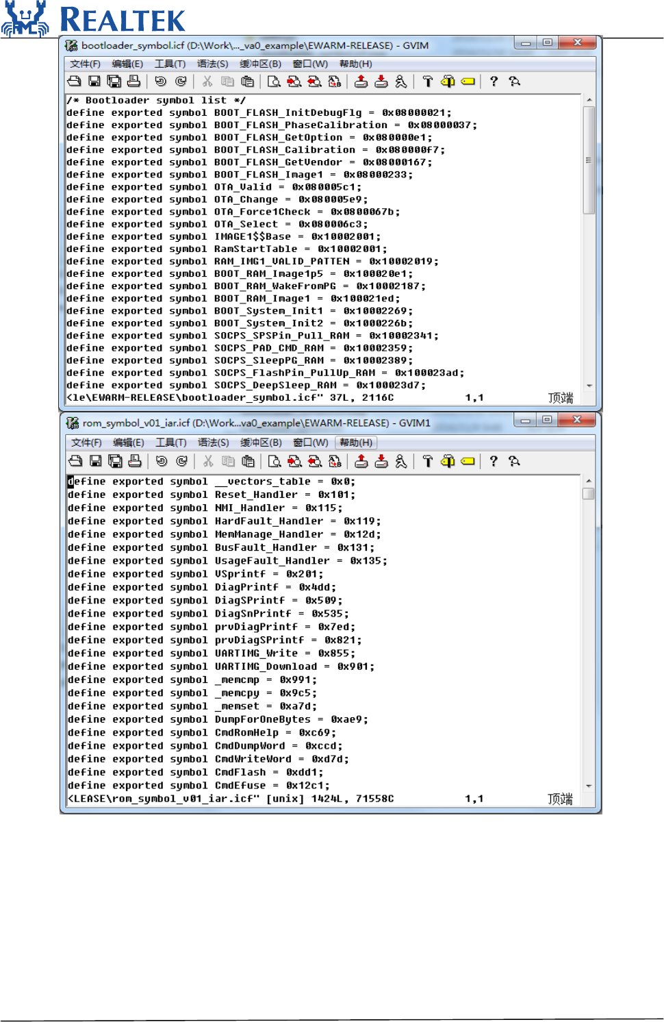
HowtosetBreakpointisshownasfollows:
Bytheway,ROMcodeandBootloadercodeisprovidedbymeansofthesymbollisttables,
rom_symbol_v01_iar.icfandbootloader_symbol.icf.Youcanfinditin
project\realtek_amebaz_va0_example\EWARM‐RELEASE.Soifyouaretrackingtothefunction
whichisrunningintheROMorbootloaderarea,thesourcecodecan’tbelocated.
RTL8710BN
2017‐12‐2612
RTL8710BN
2017‐12‐2613
5.Imagetooldownload
PleasereferenceAN0112RealtekAmeba‐ZImageToolusermanual.doc.pdffordetails.
AssumingthattheImageToolonPCisServer,whichsendsimagesfilestoAmeba‐Z(Client)through
UART.ClientorServer,whicheverstartsfirstwillbeok.
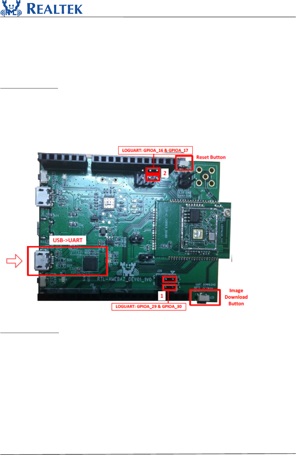
StepsonAmeba‐Z
Step1:ForQFN32,pinsmarkedwith“1”onthefigureshouldbeconnectedbyjumpercap.
ForQFN48&QFN68,pinsmarkedwith“2”shouldbeconnectedbyjumpercap.
Step2:PushtheImageDownloadButtonandkeepitpressed.
Step3:PowerontheboardorpresstheResetButton.NowAmeba‐ZgoesintoUARTDOWNLOAD
mode.
Step4:FinallyreleasetheImageDownloadButton.Nowtheclientisreadyforreceivingdata.
Figure5‐1AmebaZDEV
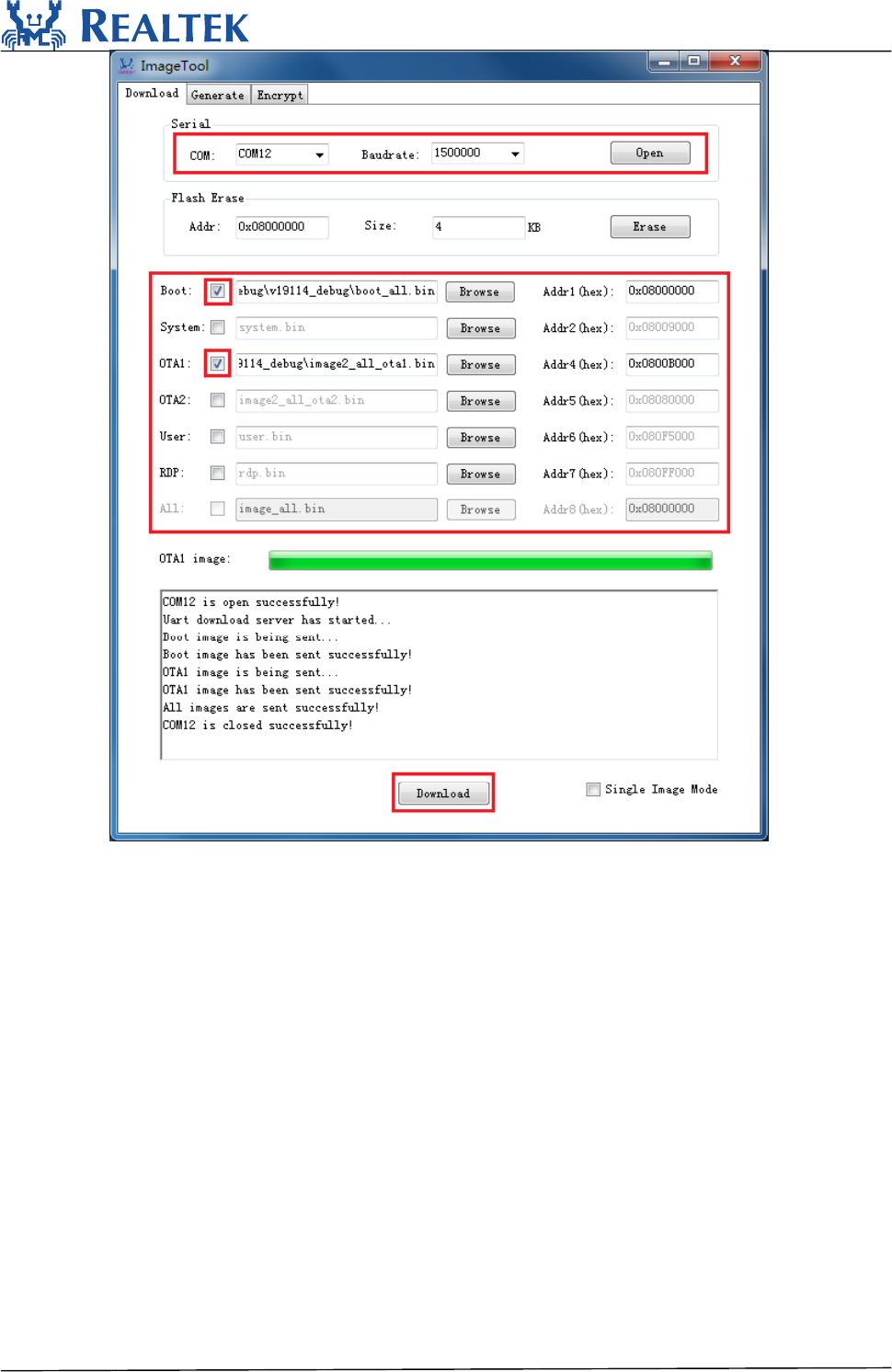
Stepsonimagetool
Step1:Selectserialport.Thedefaultbaudrateis1.5Mbps.
Step2:Selecttransmissionbaudrate
Step3:Openserialport
Step4:Checktheimagestobetransferred
Step5:SelectandloadimagesfilesbybrowsingwhicharegeneratedbyIARproject.
Step6:Inputimageaddresses.Theaddresswhichstartswith0x08isforflash,and0x10forRAM.
Step7:PushDownloadbuttontostart.Nowtheserverisreadytosenddata.
RTL8710BN
2017‐12‐2614
①
②
③
Figure5‐2ImageDownloadTabpage
Whentheclientandserverarebothready,datatransmissionbegins.
Theprogressbarwillshowthetransmitprogressofeachimage.Youcanalsogetthemessageof
operationsuccessfulorerrorsoccurfromlogwindow.
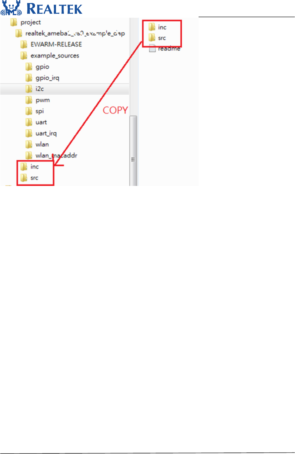
6.Howtouseperipheralsamplecode
Thereareseveralperipheralexamplecodeunderfolder“project\realtek_amebaz_va0_example
\example_sources\”,youcancopy&pastetheexample’s“inc”and“src”toprojectfolder.
Ex.Tousei2cexamplecode,youcancopy“src”and“inc”from“project\
realtek_amebaz_va0_example\example_sources\i2c\”.
RTL8710BN
2017‐12‐2615
AmebaAPIfollowsMBEDAPI.UsercancheckMBEDwebsiteforperipheralAPI.
7.Warning
7.1FederalCommunicationCommissionInterferenceStatement
FederalCommunicationCommissionInterferenceStatement
ThisequipmenthasbeentestedandfoundtocomplywiththelimitsforaClassBdigitaldevice,
pursuanttoPart15oftheFCCRules.Theselimitsaredesignedtoprovidereasonableprotection
againstharmfulinterferenceinaresidentialinstallation.Thisequipmentgenerates,usesandcan
radiateradiofrequencyenergyand,ifnotinstalledandusedinaccordancewiththeinstructions,
maycauseharmfulinterferencetoradiocommunications.However,thereisnoguaranteethat
interferencewillnotoccurinaparticularinstallation.Ifthisequipmentdoescauseharmful
interferencetoradioortelevisionreception,whichcanbedeterminedbyturningtheequipment
offandon,theuserisencouragedtotrytocorrecttheinterferencebyoneofthefollowing
measures:
●Reorientorrelocatethereceivingantenna.
●Increasetheseparationbetweentheequipmentandreceiver.
●Connecttheequipmentintoanoutletonacircuitdifferentfromthattowhichthereceiveris
connected.
●Consultthedealeroranexperiencedradio/TVtechnicianforhelp.
ThisdevicecomplieswithPart15oftheFCCRules.Operationissubjecttothefollowingtwo
conditions:(1)Thisdevicemaynotcauseharmfulinterference,and(2)thisdevicemustacceptany
interferencereceived,includinginterferencethatmaycauseundesiredoperation.
FCCCaution:Anychangesormodificationsnotexpresslyapprovedbythepartyresponsiblefor
compliancecouldvoidtheuser'sauthoritytooperatethisequipment.

RTL8710BN
2017‐12‐2616
IMPORTANTNOTE:
FCCRadiationExposureStatement:
ThisequipmentcomplieswithFCCradiationexposurelimitssetforthforanuncontrolled
environment.Thisequipmentshouldbeinstalledandoperatedwithminimumdistance20cm
betweentheradiator&yourbody.
IEEE802.11bor802.11goperationofthisproductintheU.S.A.isfirmware‐limitedtochannels1
through13.
ThismoduleisintendedforOEMintegrator.TheOEMintegratorisresponsibleforthecompliance
toalltherulesthatapplytotheproductintowhichthiscertifiedRFmoduleisintegrated.
Additionaltestingandcertificationmaybenecessarywhenmultiplemodulesareused.
20cmminimumdistancehastobeabletobemaintainedbetweentheantennaandtheusersfor
thehostthismoduleisintegratedinto.Undersuchconfiguration,theFCCradiationexposurelimits
setforthforanpopulation/uncontrolledenvironmentcanbesatisfied.
USERSMANUALOFTHEENDPRODUCT:
Intheusersmanualoftheendproduct,theenduserhastobeinformedtokeepatleast20cm
separationwiththeantennawhilethisendproductisinstalledandoperated.Theenduserhasto
beinformedthattheFCCradio‐frequencyexposureguidelinesforanuncontrolledenvironment
canbesatisfied.Theenduserhastoalsobeinformedthatanychangesormodificationsnot
expresslyapprovedbythemanufacturercouldvoidtheuser'sauthoritytooperatethisequipment.
Ifthesizeoftheendproductissmallerthan8x10cm,thenadditionalFCCpart15.19statementis
requiredtobeavailableintheusersmanual:ThisdevicecomplieswithPart15ofFCCrules.
Operationissubjecttothefollowingtwoconditions:(1)thisdevicemaynotcauseharmful
interferenceand(2)thisdevicemustacceptanyinterferencereceived,includinginterferencethat
maycauseundesiredoperation.
LABELOFTHEENDPRODUCT:
Thefinalendproductmustbelabeledinavisibleareawiththefollowing"ContainsTXFCCID:
TX2‐RTL8710BN".If the labelling area is larger than the palm of the hand, then the following
FCC part 15.19 statement has to also be available on the label: This device complies with
Part 15 of FCC rules. Operation is subject to the following two conditions: (1) this device
may not cause harmful interference and (2) this device must accept any interference
received, including interference that may cause undesired operation.
Antennalist:
Ant.BrandModelName(P/N)AntennaTypeConnectorGain(dBi)
1REALTEKAmeba‐AM0001PrintedAntennaN/A2.9
2JOYMAXTWF‐614XMPXX‐500DipoleAntennaI‐PEX3.0
3LYNwaveALA110‐222050‐300010PIFAAntennaI‐PEX3.5
Note:TheEUThasthreetypeantennas.

RTL8710BN
2017‐12‐2617
7.2NCC 警語
經型式認證合格之低功率射頻電機,非經許可,公司、商號或使用者均不得擅自變更頻率、
加大功率或變更原設計之特性及功能。
低功率射頻電機之使用不得影響飛航安全及干擾合法通信;經發現有干擾現象時,應立即停
用,並改善至無干擾時方得繼續使用。前項合法通信,指依電信法規定作業之無線電通信。
低功率射頻電機須忍受合法通信或工業、科學及醫療用電波輻射性電機設備之干擾。
本模組於取得認證後將依規定於模組本體標示審驗合格標籤, 並要求平台廠商於平台上標示
「本產品內含射頻模組: CC XX xx LP yyy Zz」。