Realtek Semiconductor RTU7105WVGA UWB WVGA Adapter User Manual
Realtek Semiconductor Corp. UWB WVGA Adapter
TX2RTU7105WVGA User Manual

使用手冊
1
All Rights Reserved by Realtek Corp.
Realtek UWB Wireless VGA Adapter
User’s Guide
Revision A
Author : Binson Tseng
Date : 11/06/2008
Realtek Corp.
使用手冊
2
All Rights Reserved by Realtek Corp.
Table of Contents
1. Introduction.................................................................................................................... 3
2. System Description ........................................................................................................ 3
2.1. UWB PHY and MAC ........................................................................................ 4
2.2. USB-to-Video .................................................................................................... 5
2.3. Display controller............................................................................................... 5
2.4. Memory.............................................................................................................. 5
3. Hardware Interfaces ....................................................................................................... 5
3.1. VGA Interface.................................................................................................... 5
4. Document History.......................................................................................................... 6
使用手冊
3
All Rights Reserved by Realtek Corp.
1. Introduction
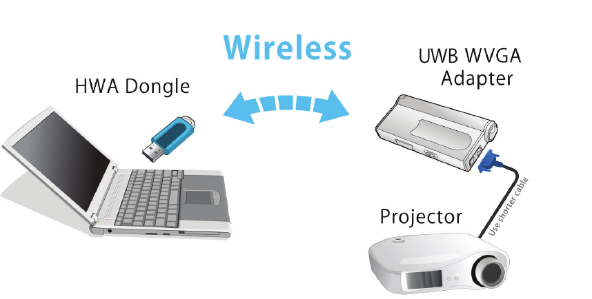
This document describes the system, operations, and interfaces of the UWB
Wireless VGA Adapter Demo Board. For WUSB application, a dongle is used
as the host controller, and connect wirelessly to a video device with the
WVGA adapter.
WVGA Application
2. System Description
The UWB WVGA adapter supports the following functions:
Certified WUSB mode
Support 53.3M, 80M, 106.7M, 160M, 200M, 320M, 400M, 480Mbps.
Support VGA interface.
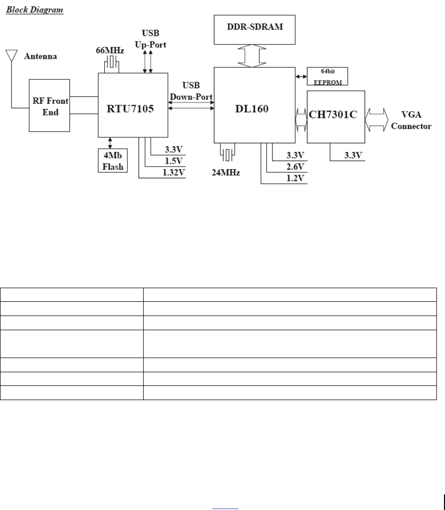
The UWB WVGA system consists of three chips – 1) Integrated UWB PHY
and MAC (RTU7105), 2) USB-to-Video chip (DL160), and 3) a display
controller IC (CH7301C). A serial flash memory (4Mb) is required to store
proper data/commands for RTU7105. To make the system work properly, the
使用手冊
4
All Rights Reserved by Realtek Corp.
Flash should be loaded with proper content by using the Flash utility provided
by Realtek. A 64bit EEPROM and a SDRAM are required for DL160.
The RF performance can also be tested using the test utility provided by
RealTek. Two clock frequencies are used in the system – 66MHz for
RTU7105 and 24MHz for DL160. Some more details of the components are
shown in the following sections. The system block diagram is shown below.
Figure 1 System Block Diagram
Product Specification
Frequency Band 3168MHz ~ 4752MHz
Network Standard WiMedia PHY 1.1 & MAC 1.0. Support PHY 1.2
Modulation Mode Multiband OFDM with QPSK, DCM
FEC Coding Rate 1/3, 1/2, 5/8, 3/4 Convolutional Coding, Reed
Solomon Coding
Support Data Rate 8 data rates from 53.3Mbps to 480 Mbps
Interface VGA interface
Support Applications Certified WUSB
2.1. UWB PHY and MAC
This chip integrates the WiMedia PHY and MAC defined by the standard.
This version of chip is packaged in 64-pin QFN form factor. The chip requires
1.5V, 1.32V and 3.3V for operation. High speed USB interface is supported.
使用手冊
5
All Rights Reserved by Realtek Corp.
2.2. USB-to-Video
DL160 provide a video port via USB interface. It is packaged in 256-ball
PBGA, and required 3.3V/2.5V IO and 1.2V core voltage.
2.3. Display controller
CH7301C is a display controller device which accepts a digital graphics input
signal, and encodes and transmits data through a DVI. The package is 64-pin
LQFP and only 3.3V is required for operation. It supports RGB and YCrCb
data formats.
2.4. Memory
4Mb flash memory and 64bit EEPROM are used by the chipset to store the
initialization data and command sequence required. SDRAM is used for video
frame buffer by DL160.
3. Hardware Interfaces
3.1. VGA Interface

使用手冊
6
All Rights Reserved by Realtek Corp.
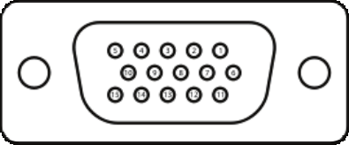
Table 1 VGA connector termination assignment
Pin# Pin Name Description
1 RED Red video
2 GREEN Green video
3 BLUE Blue video
4 N/C Not connected
5 GND Ground
6 RED_RTN Red return
7 GREEN_RTN Green return
8 BLUE_RTN Blue return
9 +5V +5V
10 GND Ground
11 N/C Not connected
12 SDA I2C data
13 HSync Horizontal sync
14 VSync Vertical sync
15 SCL I2C clock
4. Document History
Date Revision Description Author
11/06/08 A Initial Release Binson Tseng
使用手冊
7
All Rights Reserved by Realtek Corp.
Federal Communication Commission Interference Statement
This equipment has been tested and found to comply with the limits for a Class B
digital device, pursuant to Part 15 of the FCC Rules. These limits are designed to
provide reasonable protection against harmful interference in a residential
installation. This equipment generates, uses and can radiate radio frequency
energy and, if not installed and used in accordance with the instructions, may
cause harmful interference to radio communications. However, there is no
guarantee that interference will not occur in a particular installation. If this
equipment does cause harmful interference to radio or television reception, which
can be determined by turning the equipment off and on, the user is encouraged to
try to correct the interference by one of the following measures:
● Reorient or relocate the receiving antenna.
● Increase the separation between the equipment and receiver.
● Connect the equipment into an outlet on a circuit different from that to which the
receiver is connected.
● Consult the dealer or an experienced radio/TV technician for help.
FCC Caution: Any changes or modifications not expressly approved by the
party responsible for compliance could void the user’s authority to operate
this equipment.
This device complies with Part 15 of the FCC Rules. Operation is subject to the
following two conditions: (1) This device may not cause harmful interference, and
(2) this device must accept any interference received, including interference that
may cause undesired operation.
For product available in the USA/Canada market, only channel 1~11 can be
operated. Selection of other channels is not possible.
This device and its antenna(s) must not be co-located or operation in conjunction with any
other antenna or transmitter.