Recon Dynamics B0-0003 Base Station for Asset Tracking User Manual
Recon Dynamics, LLC Base Station for Asset Tracking
User Manual

PROXBOX INSTALLATION GUIDE
© 201
8
Recon Dynamics, LLC
| v1.
2
1
ProxBox Installation Guide
The ProxBox kit contains the following items needed to mount and install the Recon
Dynamics ProxBox: ProxBox, patch antenna, power cable, vibration mounting kit and
hardware and coax seal. After completing the installation be sure to visit
www.recondynamics.com
to access your account and complete the setup. Based on
information Recon receives on your company contacts, users and structure an account will
be created for you to access. Appendix A includes pictures of sample installations for your
convenience.
PROCEDURE
While this procedure is written in the context of mounting the ProxBox onto a
vehicle, it also applies to mounting the ProxBox to any piece of equipment which can
supply constant 12 volt DC power to the box.
PRE-INSTALLATION
Compare with the list of contents provided with the kit. If any discrepancies are
found, contact the Recon Dynamics customer service department.
P
ROX
B
OX
• Inspect the truck prior to installing the ProxBox to determine the best location for
mounting the ProxBox and antenna.
• Document any information regarding the vehicle or equipment the ProxBox is being
installed on for input into the Recon system.
• Document the serial number of the ProxBox for input into the Recon system.
• Criteria for mounting a ProxBox:
o Mount the ProxBox on a surface large enough that all 4 mounting points can
be used.
o Mount the ProxBox close enough to the front of a truck so the power cable
can be hooked up to the truck's main battery with the supplied cable length.
Extending the supplied power cord is acceptable to increase mounting
options.
o Mount the ProxBox such that no tools or equipment will damage it while they
are in use or being stored on the truck.
o Mount the ProxBox as high as possible and as far away from any nearby
metal obstructions to minimize interference with the gray top.
o See Appendix A for installation examples.

PROXBOX INSTALLATION GUIDE
© 201
8
Recon Dynamics, LLC
| v1.
2
2
It may be necessary to fabricate a mounting plate or structure to create the proper
mounting condition for the ProxBox and patch antenna, which would then need to
be mounted (welded or bolted), to the truck.
P
ATCH
A
NTENNA
• The recommended placement of the patch antenna should be located as high as
possible with a good visibility to the back of the truck and separated as far away
from the ProxBox as possible. Depending on the location of the battery, a typical
installation has the ProxBox mounted on the driver’s side of the vehicle and the
patch antenna mounted on the passenger’s side roughly 2-3 feet away.
• Document the serial number of the Beacon (optional) attached to the side of the
antenna for input into the Recon system if one is present.
• Criteria for mounting the patch antenna:
o Mount the patch antenna such that the antenna front (curved portion) is
facing to the back of the truck. The best location is typically directly behind
the cab of the truck.
o Mount the patch antenna close enough to the ProxBox so the antenna cable
can be connected to the ProxBox with the supplied cable length without
stressing the connector.
o Mount the patch antenna such that no tools or equipment will damage it
while they are in use or being stored on the truck.
o Mount the antenna as high as possible to minimize any interference.
o See Appendix A for installation examples.
PROXBOX INSTALLATION GUIDE
© 201
8
Recon Dynamics, LLC
| v1.
2
3
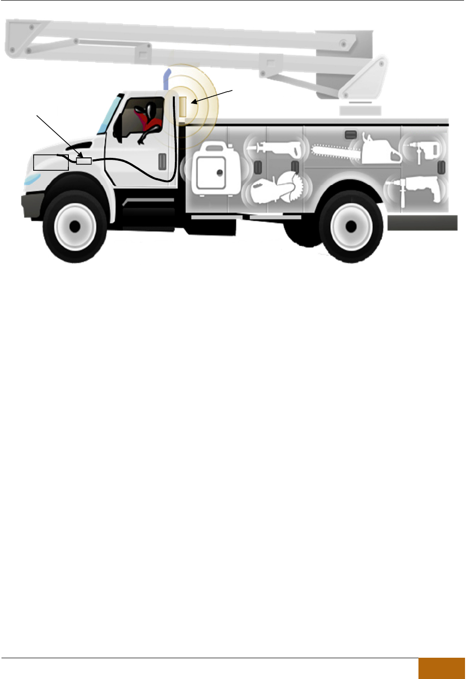
Figure 1
Figure 1 shows the typical routing of the power cable and component placement for the
ProxBox system.
ANTENNA
PROXBOX
Battery
FUSE
PROXBOX INSTALLATION GUIDE
© 201
8
Recon Dynamics, LLC
| v1.
2
4
INSTALLATION
P
ROX
B
OX
I
NSTALLATION
• Use the mounting flanges as a drill template and center punch to mark locations to
drill. Mount the ProxBox using the vibration mounting kit. Ensure all metal surfaces
are touched up with paint after drilling to avoid corrosion.
• Route supplied power cable from ProxBox to the truck's main battery, the bare end
(no connector) is to be routed.
Ensure when routing the power cable that it is well protected, so nothing can
damage it once installed.
Do not connect power to the ProxBox until patch antenna is connected.
• Secure cable to the truck using tie wraps. It is recommended to use wire loom for
added protection.
• It is best to leave the power cable at full length and just bundle up excess cable with
a wire tie. But, if necessary, cut excess length from the cable.
• Strip the pre-tinned wire leads back 2-3 inches. The 18 AWG red “hot” wire requires
and inline 10A fuse added (not included).
Shock hazard! Be very careful when connecting leads to the battery.
• Attach the black lead to ground post of the battery. Attach red lead to hot post of
battery. Ensure both connections are bolted tightly to battery and power cable fuse
is routed to eliminate potential damage.
P
ATCH
A
NTENNA
I
NSTALLATION
• Before mounting ensure antenna cable will easily reach the ProxBox connector
marked “Ant”.
• Attach Patch antenna using a minimum of (2) screws to a solid surface, (4) screws
are recommended though. Use the antenna as a drill template and center punch to
mark locations to drill. Do not over tighten screws or bolts as the antenna is plastic
and will be damaged. Ensure all metal surfaces are touched up with paint after
drilling to avoid corrosion.
Do not mount antenna using glue, tape or tie wraps.
• Route cable from patch antenna to ProxBox.
• Secure excess cable neatly using wire ties. It is recommended to use wire loom for
added protection.

PROXBOX INSTALLATION GUIDE
© 201
8
Recon Dynamics, LLC
| v1.
2
5
Ensure when routing the antenna cable that it is well protected, so nothing can
damage it once installed.
• Connect cable to ProxBox and hand tighten. Refer to Figure 2 for ProxBox port
identity.
• Wrap connector with enough coax seal tape to completely cover the connection then
mold around cable and connector to weatherize connection. Inspect to ensure
connection is fully covered.
F
INAL
P
OWER
U
P
• Re-inspect all cable routing and connections to ensure completion. Re-inspect
battery connection for proper polarity.
• Measure voltage at the power connector to verify 12 volts will be supplied to the
ProxBox.
• Connect the power connector to the ProxBox and hand tighten. Once the power cord
is fit over the power connector a final ¼ turn is required to secure the power
connection. Refer to Figure 2 for ProxBox port identity.
PROXBOX INSTALLATION GUIDE
© 201
8
Recon Dynamics, LLC
| v1.
2
6
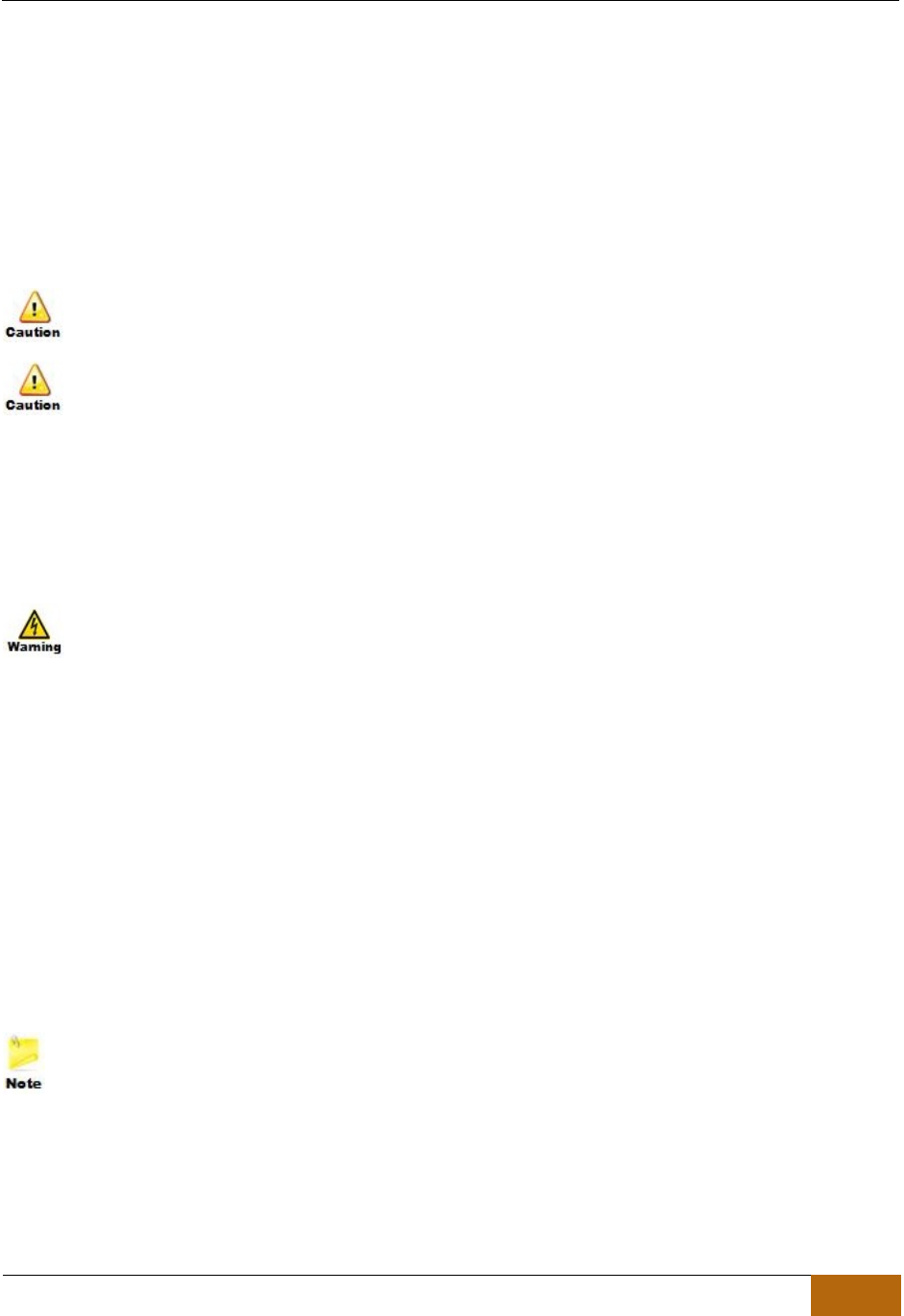
Figure 2
ProxBox
Patch Antenna
w/Vehicle Tag
Power Port
Beacon
PROXBOX INSTALLATION GUIDE
© 201
8
Recon Dynamics, LLC
| v1.
2
7
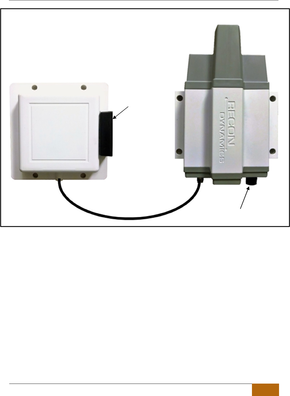
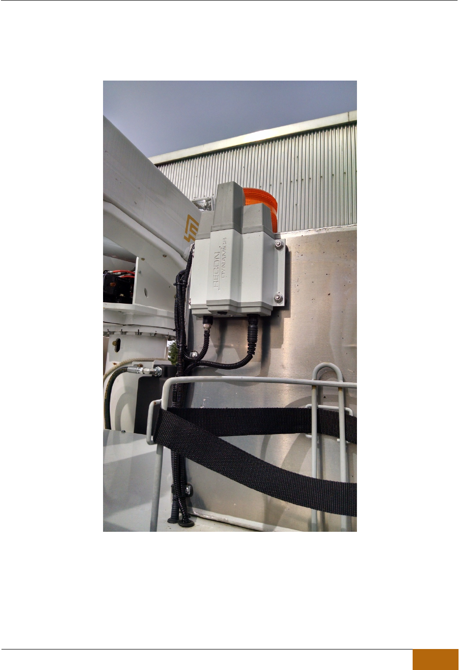
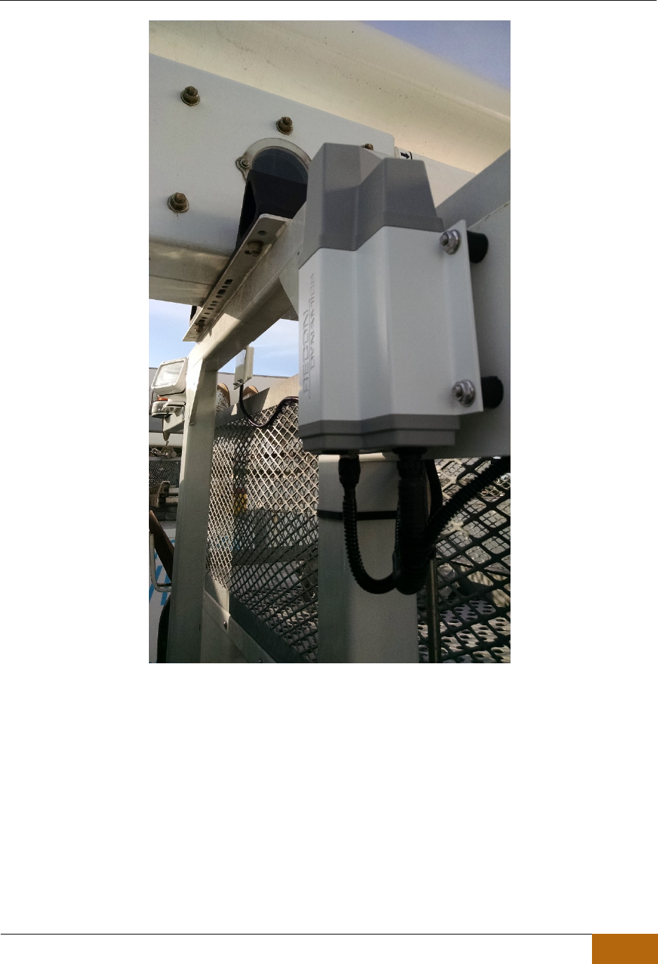
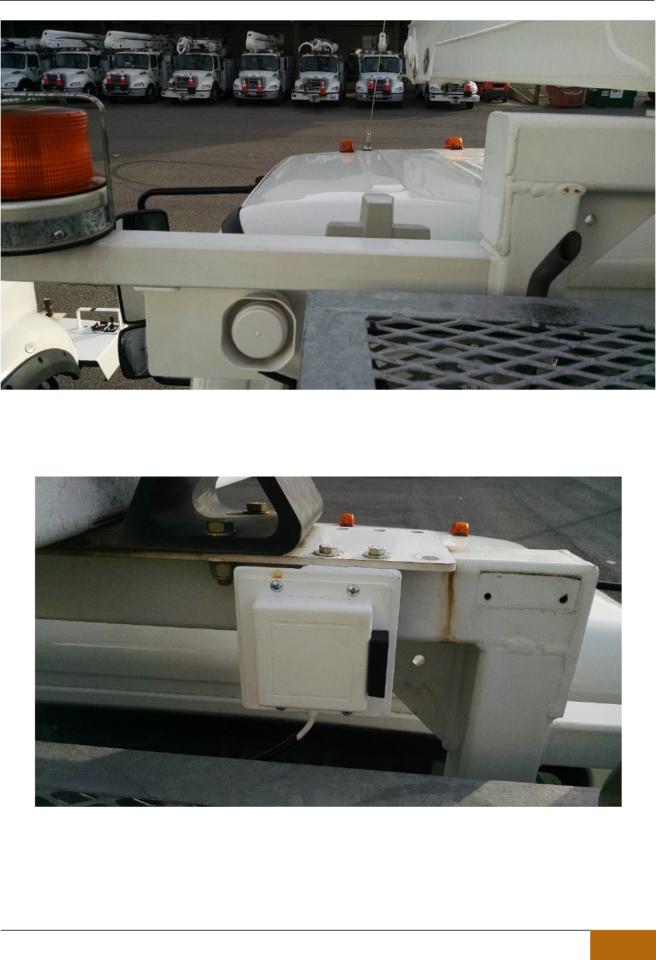
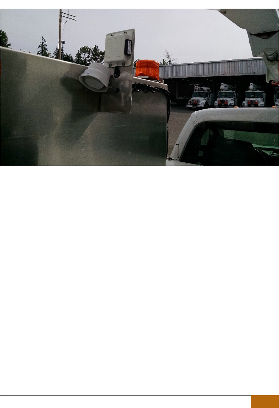
Appendix A
Appendix A includes example images of ProxBox installations including ProxBox and patch antenna.
PROXBOX INSTALLATION GUIDE
© 201
8
Recon Dynamics, LLC
| v1.
2
8
PROXBOX INSTALLATION GUIDE
© 201
8
Recon Dynamics, LLC
| v1.
2
9
PROXBOX INSTALLATION GUIDE
© 201
8
Recon Dynamics, LLC
| v1.
2
10

PROXBOX INSTALLATION GUIDE
© 201
8
Recon Dynamics, LLC
| v1.
2
11
Appendix B
Below is the LED sequence and status table.
BLUE GREEN RED STATUS
OFF OFF OFF No power
BLINK OFF OFF ProxBox initialization
ON ON ON All Good (including boom,
bucket and RASR sensors
OFF ON/BLINK
ON/BLINK ProxBox not working
ON OFF NA GPS failure
ON BLINK NA Searching GPS
ON NA OFF Cellular failure
ON NA BLINK Searching cellular connection
BLINK BLINK ON Boom sensor not OK
BLINK ON BLINK Bucket sensor not OK
BLINK BLINK BLINK RASR not OK
BLINK (Every
10 seconds)
OFF OFF ProxBox is in Hibernation
mode.
An NA in the table indicates that LED state is not relevant.

PROXBOX INSTALLATION GUIDE
© 201
8
Recon Dynamics, LLC
| v1.
2
12
T
ROUBLESHOOTING
If after 10 minutes if the ProxBox is still initializing remove the disconnect the power cord
from the ProxBox, wait 1 minute then plug back in.
If ProxBox does not initialize (Blue light on):
• Verify power to the ProxBox is between 12 and 24 volts DC
• Inspect ProxBox power connector and power cord for damage
• Inspect ProxBox for any visible damage, this may indicate the electronics inside are
damaged
If ProxBox is searching for GPS per the table:
• Ensure vehicle is not in a building or under a metal cover
• ProxBox gray top is exposed to the open sky with no metal objects directly above
• If surrounded by tall buildings move vehicle to an open area
If ProxBox is searching for a cellular connection per the table:
• Verify the serial number input into the system is correct
• Ensure vehicle is not in a building or under a metal cover
• ProxBox gray top is exposed to the open sky with no metal objects directly above
• If vehicle is in a rural area known to be outside of cellular coverage move it into a
more urban location where cellular coverage is available

PROXBOX INSTALLATION GUIDE
© 201
8
Recon Dynamics, LLC
| v1.
2
13
Appendix C
FCC
This device complies with part 15 of the FCC rules. Operation is subject to the following two conditions:
(1) This device may not cause harmful interference, and (2) this device must accept any interference
received, including interference that may cause undesired operation. Any changes or modifications not
expressly approved by manufacturer could void the user’s authority to operate the equipment.
IMPORTANT! Any changes or modifications not expressly approved by the party responsible
for compliance could void the user’s authority to operate this equipment.
47 CFR 15.505- FCC
Class B
For a Class B digital device or peripheral, the instructions furnished the user shall include the
following or similar statement, placed in a prominent location in the text of the manual:
NOTE: This equipment has been tested and found to comply with the limits for a Class B digital
device, pursuant to part 15 of the FCC Rules. These limits are designed to provide reasonable
protection against harmful interference in a residential installation. This equipment generates,
uses and can radiate radio frequency energy and, if not installed and used in accordance with the
instructions, may cause harmful interference to radio communications. However, there is no
guarantee that interference will not occur in a particular installation. If this equipment does cause
harmful interference to radio or television reception, which can be determined by turning the
equipment off and on, the user is encouraged to try to correct the interference by one or more of
the following measures:
—Reorient or relocate the receiving antenna.
—Increase the separation between the equipment and receiver.
—Connect the equipment into an outlet on a circuit different from that to which the receiver
is connected.
—Consult the dealer or an experienced radio/ TV technician for help.
This product is designed for a specific application and needs to be installed by qualified
personnel who have RF and related rule knowledge. The general user shall not attempt to install
or change the setting or installation location. The product shall be installed at a location where
the radiating antenna can be kept 20 cm from nearby personnel in normal operation
conditions to meet regulatory RF exposure requirements. External antenna; use only the
antennas which have been approved by the applicant. The non-approved antenna(s) may
produce unwanted spurious or excessive RF transmitting power which may lead to the violation
of FCC/IC limits and is prohibited.