Recon Dynamics B2-0014 Proxlet asset tag and safety system sensor. User Manual
Recon Dynamics, LLC Proxlet asset tag and safety system sensor.
User Manual

© 2018 RECON Dynamics, LLC
RECON Dynamics
Proxlet Installation Guide
v1.1

P R O X L E T I N S T A L L A T I O N G U I D E
© 2018 RECON Dynamics, LLC P a g e | 2
Table of Contents
Proxlet ........................................................................................................ 3
Key Details ........................................................................................ …………….3
Installation Preparation ............................................................................... 4
Installing the Proxlet.................................................................................... 4
Tools .................................................................................................. …………….4
Equipment ......................................................................................... …………….5
Numbering Tools ........................................................................................ 5
Process for Gluing ...................................................................................... 5
Process for Taping ...................................................................................... 6
Alternate Installations (Cables) ................................................................... 6
Proxlet Installation Preparation ................................................................... 7
Materials Needed .............................................................................. …………….7
Tools needed ..................................................................................... …………….7
Workspace Environment ................................................................... …………….7
Appendix A ................................................................................................. 8
Installation Examples ......................................................................... …………….8
Appendix B ............................................................................................... 13
Equipment and Material References ................................................. …………...13
Attaching Proxlets to tools and equipment ....................................................................... 13
Adding asset numbers to tools .......................................................................................... 13
Appendix C ............................................................................................... 14
FCC ................................................................................................... …………...14
P R O X L E T I N S T A L L A T I O N G U I D E
© 2018 RECON Dynamics, LLC P a g e | 3
Proxlet
The Proxlet tag is the enabler of RECON Dynamics Asset Management Solution to actively manage
assets such as equipment, tools and material providing unprecedented visibility for a company’s
operations. This tiny, rugged tag hides inside or on assets and wirelessly conveys information to the
ProxBox
™
hub. The Proxlet is designed to operate in the most extreme environments. When
combined with the ProxBox, the Proxlet offers a full range of sensing and tracking capabilities. The
Proxlet is part of RECON Dynamics unique web-based cloud-hosting solution for asset
management providing information and metrics to any internet connected device.
• This document provides guidelines for safe and permanent installation of RECON
Dynamics tool tag (Proxlet) on tools and equipment.
• Please refer to your RECON Asset Management Solution (RAMS) user guide for
additional information.
Read and understand all instructions and warnings provided for the Proxlet as well as
any other supporting materials for such things as solvents or glues needed when
installing the Proxlet.
Be careful not to damage the housing or peel off the Proxlet label during installation.
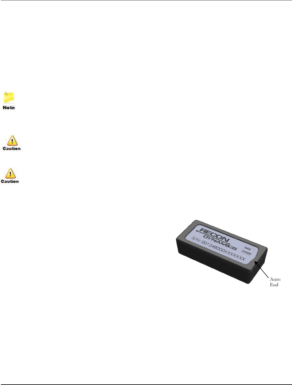
Key Details
• The antenna of the Proxlet is at the end
designated by the pointed section of the
label as shown in figure 1.
• The label on the Proxlet contains a unique
alphanumeric serial number and a scan-
able barcode of that number.
• The barcode type is data matrix so the
proper 2D reader must be selected to read
the bar code.
• This product is designed for
indoor/outdoor use and is weather-proof allowing it to be installed on most equipment and
tools. If the seal of the Proxlet is compromised, it will not function long term in an outdoor
environment.
• The housing is made of ABS plastic. Ensure any adhesives, chemicals or solvent used during
installation is compatible with ABS.
Antenna
End
Figure 1
P R O X L E T I N S T A L L A T I O N G U I D E
© 2018 RECON Dynamics, LLC P a g e | 4
Installation Preparation
Metal objects blocking radio frequency (RF) transmission can affect the range of the
Proxlet.
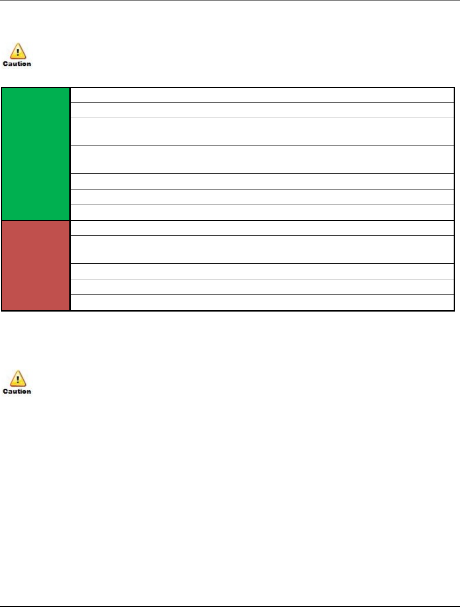
Below are some general do(s) and don’t(s) to help identify a good Proxlet mounting location
DO
Mount the Proxlet inside tools when possible for protection while tool is in use.
Look for a surface that is flat, well protected and free from dents and scratches.
Look for cavities or small open areas where the Proxlet can be discretely tucked and
easily secured.
Mount the antenna end toward the outside of the tool or equipment and away from
metal when possible.
Mount the Proxlet such that the barcode is accessible if possible.
Mount Proxlet on its bottom surface (surface opposite label) when possible.
Mount the Proxlet such that it does not void any tool warranties.
DO
NOT
Mount close to a heat source.
Mount on surfaces which are fully exposed to damage while the tool or equipment is
in use when possible.
Mount where the Proxlet is fully surrounded by metal.
Mount the Proxlet such that it affects the functionality of the tool or equipment.
Mount to areas that do not have sufficient flat mounting surfaces.
Installing the Proxlet
• Ensure proper use of safety equipment prior to beginning the installation process
There are several ways and locations to properly install a Proxlet, depending widely on what it’s
being installed on. Below are a few examples:
Tools
• Inside plastic, fiberglass or wood sections, handles, covers, etc.
• Outside surface of tool in well protected flat areas
• In tools cases that are guaranteed to stay with the tool
• Heat shrink or taped onto cable
• Fit into sewn edges of bags or ground matts
• Make an attachment surface/bracket, for the Proxlet that can be added to the tool
P R O X L E T I N S T A L L A T I O N G U I D E
© 2018 RECON Dynamics, LLC P a g e | 5
Equipment
• Outside surface of equipment in well protected flat areas
• Inside plastic registration box or storage bin
• Inside cab area
First, try to find a location inside or on the tool or equipment where the Proxlet is less likely to be
damaged. In some instances, no glue or tape is required to secure the Proxlet inside a tool if
it fits tightly and is contained from moving. Remember, the Proxlet is a RF transmitter and can
only be fully contained inside none metallic materials. If a tool is stored in a metal bin, ensure the
bin door has a rubber weather seal. RF signal will penetrate through weather seals. In the case where
a tool is stored in a metal bin, the RF signal strength will be degraded but likely still be received by
ProxBoxes on vehicles or in tool rooms.
Metal objects blocking radio frequency (RF) transmission can affect the range of the Proxlet
Numbering Tools
The RAMS system generates a unique ID for tools which needs to be physically added to the tool.
Refer to the appendix for reference to devices used for numbering. Equipment typically will have an
asset number already. There are several ways to add these numbers, some are listed below:
• Engraving
• Stamping
• Permanent Paint Marker
Process for Gluing
A permanent fast setting epoxy is recommended for gluing the Proxlet to tools and equipment. In
general, this technique will be the most widely used for installing Proxlets due to the wide variety of
surfaces the installer will see. Refer to the appendix for reference to an epoxy. Below are steps to
properly install a Proxlet to tools and equipment with a glue.
For fast setting epoxies, it is recommended to store the epoxy in ice while not in use to
prolong the life of the mixing nozzle
1. Scan the Proxlet QR barcode and assign to a tool/equipment in the database, refer to the RAMS
user guide for more instructions.
2. Identify the tool/equipment model number, serial number and any other identifier so it can be
easily tracked and log information in the RAMS database.
3. Identify on the tool or equipment where the Proxlet will be installed
P R O X L E T I N S T A L L A T I O N G U I D E
© 2018 RECON Dynamics, LLC P a g e | 6
4. Use 120-grit sandpaper to slightly scuff contact surfaces and remove any remaining
contaminants. This will enhance the contact strength of a glue.
5. Use an alcohol based solvent to thoroughly clean the surfaces where the Proxlet will be glued to.
6. It is recommended to also clean the Proxlet (steps 3 above) to prepare it for mounting.
7. Apply glue to Proxlet using a moderate amount and attached to tool or equipment. Remember,
most permanent epoxies require a thin bond line for maximum strength. In the case where the
mounting surface of the tool or equipment is not flat or has a very rough surface more glue may
be required.
8. Depending on the glue chosen or ambient temperature the Proxlet may need to be held in place
for a few seconds up to a minute or two to stay in place.
9. Add the RAMS generated number to the tool. Refer to the RAMS user guide for more
instructions.
It is recommended to use nitrile gloves or equivalent when working with glues and solvents
Process for Taping
Strong double back tape rated for outdoor use can also be used for installing a Proxlet. Though not
as adaptable as an epoxy, tape can create a permanent bond in the right application. Follow the
process for gluing but do not rough the mating surface of the tool. Tape works best on smooth flat
clean surfaces. Refer to the appendix for reference to a tape.
Alternate Installations (Cables)
DO NOT overheat the Proxlet while using a heating element such as a heat gun
1. Begin by referring to steps 1 and 2 above for installing the Proxlet.
2. Identify the length of cable and any other useful information.
3. Prepare the cable by removing cable clamp brackets and clamp from one of the cable ends.
4. Cut a 6" piece of an appropriately sized diameter transparent heat shrink tubing.
5. Slide the heat shrink over the end of the ground cable until it is about 8"-12" from the end.
6.
Insert a prepared Proxlet into the heat shrink so that it is centered in the tubing.
7.
Use a label printer to print the number generated by the RAMS system and add to visible surface of
the Proxlet.
8.
Use a heat gun on a low setting to shrink the tubing around the cable and Proxlet.
Be careful not to
overheat the Proxlet by applying heat directly on it.
9. Quickly wave the heat gun back and forth over the heat shrink until the tubing has contracted around
the cable.
10. Reassemble the cable end and secure the clamp brackets.

P R O X L E T I N S T A L L A T I O N G U I D E
© 2018 RECON Dynamics, LLC P a g e | 7
Proxlet Installation Preparation
Materials Needed
• 0.5L Isopropyl (Rubbing) Alcohol
• 120-grit Sandpaper
• Epoxy
• Double Back Tape
• Heat Shrink Tubing
• Work related apparel
• Nitrile Gloves
• Safety glasses
Tools needed
• Engravers (for soft and hard materials)
• Metal stamp
• Permanent Paint Markers
• Heat Gun
• Power Driver and bit set for disassembly of tools and equipment
Workspace Environment
• All work should be performed on a long set of workbenches with ample space to setup
different stations for each part of the install. General work stations typically consist of
the following:
1. Computer station for data input and scanning of Proxlet
2. Tool disassembly and preparation
3. Proxlet installation
4. Glue curing and tool re-assembly
• It is recommended to cover the workbenches with tarps or drop clothes as needed to
protect tools from scratches and guard against spills such as glue or solvents.
• It is recommended to work at room temperature - 68-72˚F to maintain a reasonable
curing time for glue or tack time for tape. If possible, work indoors in a dry space.
A P P E N D I X
© 2018 RECON Dynamics, LLC P a g e | 8
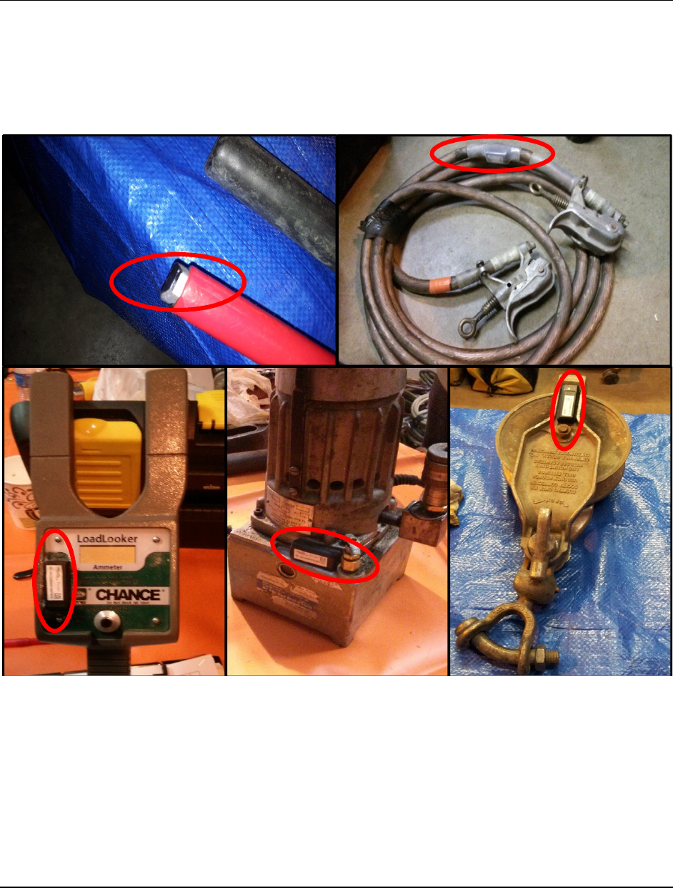
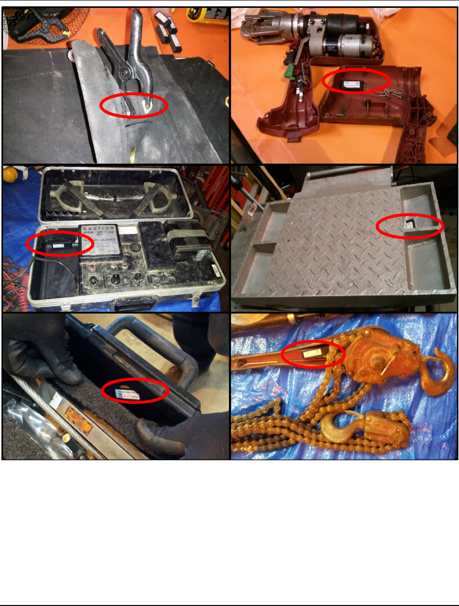
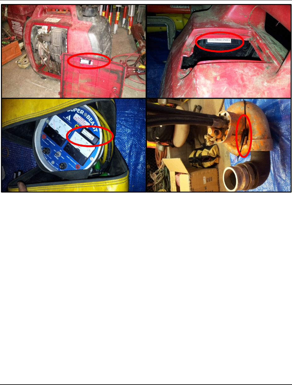
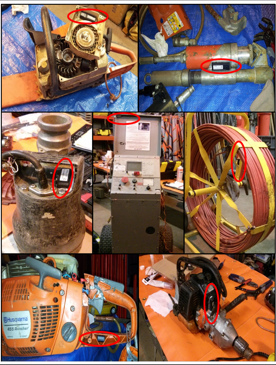
Appendix A
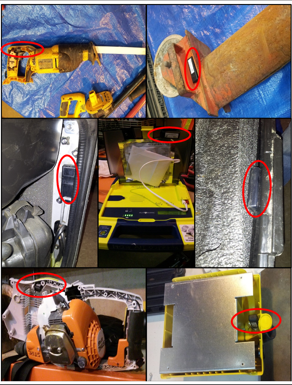
Installation Examples
• The following images are examples of Proxlets installed on tools and equipment.
A P P E N D I X
© 2018 RECON Dynamics, LLC P a g e | 9
A P P E N D I X
© 2018 RECON Dynamics, LLC P a g e | 10
A P P E N D I X
© 2018 RECON Dynamics, LLC P a g e | 11
A P P E N D I X
© 2018 RECON Dynamics, LLC P a g e | 12

A P P E N D I X
© 2018 RECON Dynamics, LLC P a g e | 13
Appendix B
Equipment and Material References
RECON recommends using a laptop and mouse with windows 7 or newer for scanning S/N of Proxlet into the
system
The following links to products and material are for reference only.
2D barcode reader
http://www.newegg.com/Product/Product.aspx?Item=N82E16838129176
Part number is GD4430-BK. Most any 2D general purpose readers will work, if cable does not come with it
order 90A052065.
Attaching Proxlets to tools and equipment
Double back tape for attaching to clean smooth surfaces
https://www.amazon.com/3M-Automotive-Acrylic-Attachment-Black/dp/B000P18N76
Epoxy for all other surfaces
Epoxy (DP8405 or DP8805 (sets faster)) - http://www.rshughes.com/p/3M-Scotch-Weld-DP8405NS-Green-
Multi-Part-Duo-Pak-Standard-MMA-Acrylic-Adhesive-45-Ml-Cartridge-5-Min-Working-Time-Shear-Strength-
4100/051115_68963/
Applicator - http://www.rshughes.com/p/3M-Scotch-Weld-EPX-Plus-II-50004-Applicator-Gun-Supports-50-Ml-
Duo-Pack-Cartridges-Manual-2-1-Mix-Ratio/021200_50004/
Nozzle - http://www.rshughes.com/p/3M-Scotch-Weld-EPX-Noz-Nozzle-For-Use-With-45-Ml-Scotch-Weld-Duo-
Pak-Cartridges-10-1-Mix-Ratio/051115_69043/
Plunger - http://www.rshughes.com/p/3M-Scotch-Weld-EPX-Plunger-Cartridge-Plunger-For-Use-With-Duo-Pak-
Cartridges-10-1-Mix-Ratio/051115_69044/
Adding asset numbers to tools
Engraving Pen for soft surfaces
https://www.dremel.com/en-us/tools/pages/ToolDetail.aspx?pid=290#.V2mHc_krKcY
Dremel with small round tip for harder surfaces
https://www.dremel.com/en-us/tools/Pages/ToolDetail.aspx?pid=4000-4%2f36H#.V2mIBvkrKcY
Letter and number Stamp Set for some unique hard surfaces
http://www.homedepot.com/p/TEKTON-5-32-in-Letter-and-Number-Stamp-Set-36-Piece-
6610/205642674?MERCH=REC-_-NavPLPHorizontal1_rr-_-NA-_-205642674-_-N
Paint markers for all other surfaces
http://www.staples.com/uni-Paint-Markers/product_SS1003205

A P P E N D I X
© 2018 RECON Dynamics, LLC P a g e | 14
Appendix C
FCC
This device complies with part 15 of the FCC rules. Operation is subject to the following two
conditions: (1) This device may not cause harmful interference, and (2) this device must accept
any interference received, including interference that may cause undesired operation. Any
changes or modifications not expressly approved by manufacturer could void the user’s authority
to operate the equipment.
IMPORTANT! Any changes or modifications not expressly approved by the party responsible
for compliance could void the user’s authority to operate this equipment.
47 CFR 15.505- FCC
Class B
For a Class B digital device or peripheral, the instructions furnished the user shall include the
following or similar statement, placed in a prominent location in the text of the manual:
NOTE: This equipment has been tested and found to comply with the limits for a Class B digital
device, pursuant to part 15 of the FCC Rules. These limits are designed to provide reasonable
protection against harmful interference in a residential installation. This equipment generates,
uses and can radiate radio frequency energy and, if not installed and used in accordance with the
instructions, may cause harmful interference to radio communications. However, there is no
guarantee that interference will not occur in a particular installation. If this equipment does cause
harmful interference to radio or television reception, which can be determined by turning the
equipment off and on, the user is encouraged to try to correct the interference by one or more of
the following measures:
—Reorient or relocate the receiving antenna.
—Increase the separation between the equipment and receiver.
—Connect the equipment into an outlet on a circuit different from that to which the receiver
is connected.
—Consult the dealer or an experienced radio/ TV technician for help.
Radiation Exposure Statements
For FCC
FCC Radiation Exposure Statement
This equipment complies with FCC radiation exposure limits set forth for an uncontrolled
environment.