Red Point Positioning RPPARNV4 Real Time Location System User Manual RTLS Development Kit Quick Start Guide
Red Point Positioning Corporation Real Time Location System RTLS Development Kit Quick Start Guide
Contents
- 1. User manual
- 2. Users manual
Users manual
Red Point
Positioning
© 2015, Red Point Positioning Corp. DOCK # Total 11 pages
RTLS Development Kit Quick Start Guide
Version 1.1
Abstract
This quick start guide shows the steps to quickly set up a simple RTLS demonstration system using the
development kit.
Category: Public
Revision History
Revision
Date
Author
Notes
1.0
22-Sep-15
Anton Shpakovskiy
1.1
05-Oct-15
Chunjie Duan
add FCC and IC statements

9/22/2015 RTLS DEVELOPMENT KIT QUICK START GUIDE
© 2015, Red Point Positioning Corp. Public 2
Table of Content
Abstract ................................................................................................................................ 1
1. Before the Demonstration .............................................................................................. 3
Opening the Box............................................................................................................................................ 3
Charging Radio Nodes ................................................................................................................................... 4
Installing Software ........................................................................................................................................ 4
2. Setting up the Demonstration ......................................................................................... 4
Step 0: Finding a Space ................................................................................................................................. 4
Step 1: Connecting RBS ................................................................................................................................. 4
Step 3: Installing Anchors .............................................................................................................................. 5
Step 4: Launching End User Console ............................................................................................................. 6
Step 5: Setting Anchor Positions ................................................................................................................... 7
Step 6: Adding Mobile Nodes ....................................................................................................................... 8
Step 6: Visualizing Node Locations ............................................................................................................... 8
3. After the Demonstration ................................................................................................. 9
4. Contact Us ...................................................................................................................... 9
9/22/2015 RTLS DEVELOPMENT KIT QUICK START GUIDE
© 2015, Red Point Positioning Corp. Public 3
1. Before the Demonstration
Opening the Box
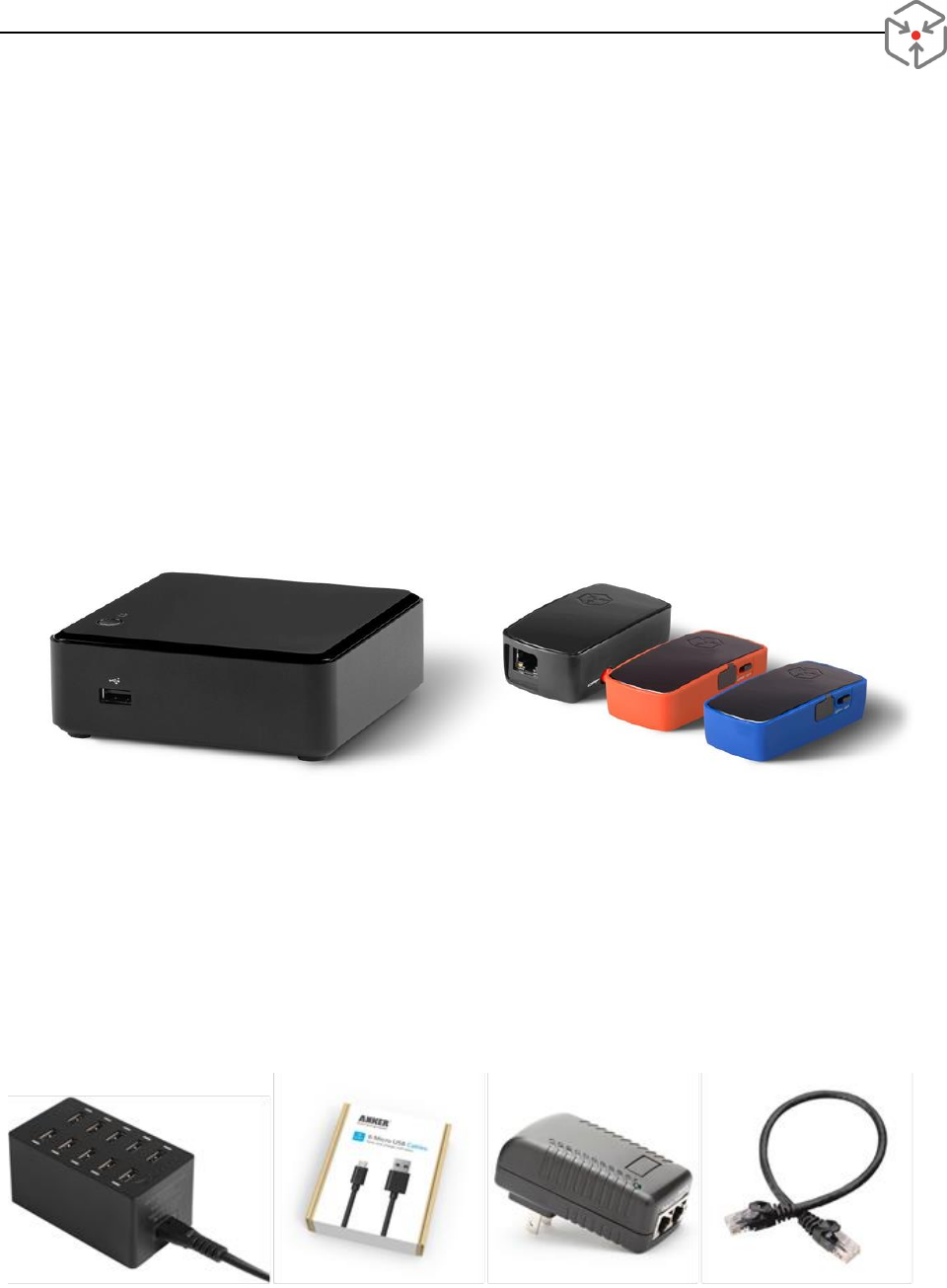
The following items are included in a standard development kit:
One (1) RTLS Base Station (RBS, also referred to as server)
Two (2) Bridge nodes in black enclosure (Bridges)
Six (6) Anchor/Mobile nodes in red enclosure (A/M nodes)
Two (2) Bluetooth nodes in blue enclosure (BT nodes)
One (1) Wi-Fi router
Two (2) Power-over-Ethernet Injector (POE)
Two (2) Ethernet cables
One (1) USB flash drive with RBS recovery image
One (1) USB flash drive with documentation and software
Figure 1 - From left to right, RBS, Bridge, F/M, and BT nodes.
The following accessories may also be included in the kit:
USB charge station
micro-USB cables
POE power injector
CAT5e patch cables
Sensors cable
Please note that a custom built kit may have different content. Please verify the content with the
quotation specifically tailored for you.
9/22/2015 RTLS DEVELOPMENT KIT QUICK START GUIDE
© 2015, Red Point Positioning Corp. Public 4
Charging Radio Nodes
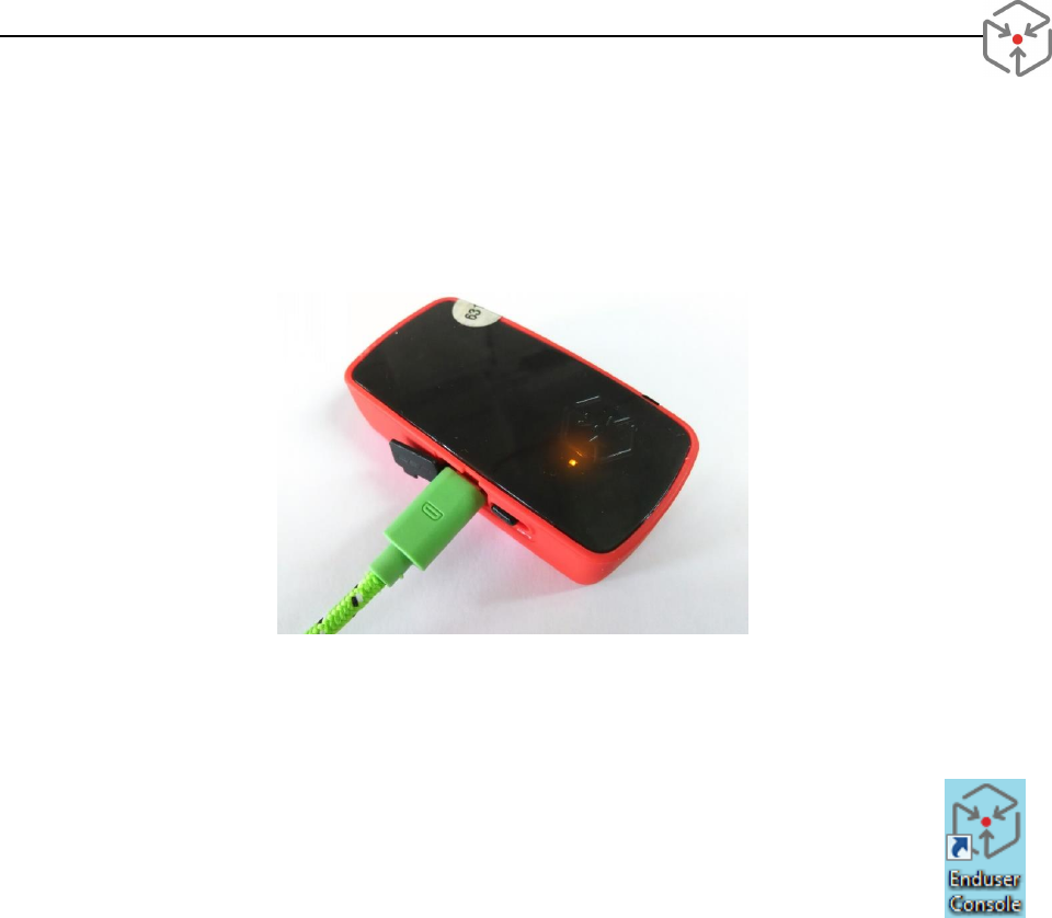
All A/M nodes and BT nodes have built-in rechargeable batteries and can be charged via the micro-USB
port. Before setting up the system, we recommend you fully charge all nodes. While a node is being
charged, a green (or yellow) LED is on. The LED is turned off when full charge is reached.
Figure 2 – Radio node at charging
Installing Software
End User Console application is a client GUI software that allows you to manage the system
and visualize the node location. The software can be found on the USB flash drive included in
the kit. Install it on a Windows® computer by running setup.exe. The installer automatically
creates an icon on your desktop. You will also find the program in the Start menu, under
Redpoint Positioning
2. Setting up the Demonstration
Step 0: Finding a Space
You will need a space to set up the demo. The kit is pre-configured for a 10m x 10m area but such a
space is not required. There is no specific requirement for the space. However, please be advised that an
open space generally gives you better location accuracy. Also the geometry of the anchors affects the
position accuracy. A long, narrow space may result in relative poor precision.
Step 1: Connecting RBS
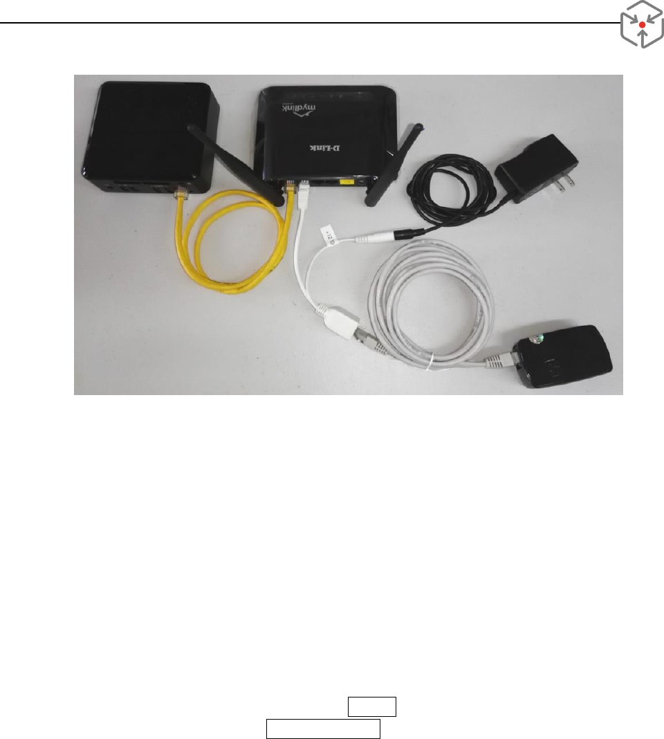
Power on the Wi-Fi router
Connect the RBS to one of the router's LAN ports using an Ethernet cable (note, do not connect
to the WAN port!)
Power on the RBS by pressing the power button briefly
o RBS is on when the blue LED is lit and the hard drive icon starts flashing
o It takes about 30 seconds to 1 minute for all RBS services to start
9/22/2015 RTLS DEVELOPMENT KIT QUICK START GUIDE
© 2015, Red Point Positioning Corp. Public 5
Figure 3 - Connection of the RBS, a POE powered bridge to the Wi-Fi router
Step 3: Installing Anchors
Anchors refer to nodes that are in static, known locations. Bridge, A/M, or even BT nodes can all be used
as anchors. Note that Anchor nodes and Fixed nodes are used interchangeably in some of Redpoint’s
documents.
You may find some radio nodes pre-labelled (e.g., SE, SW, NW, NE) in the kit. If the nodes are labelled,
simply take 1 bridge, and 3 A/M nodes. You can physically label them for easy identification.
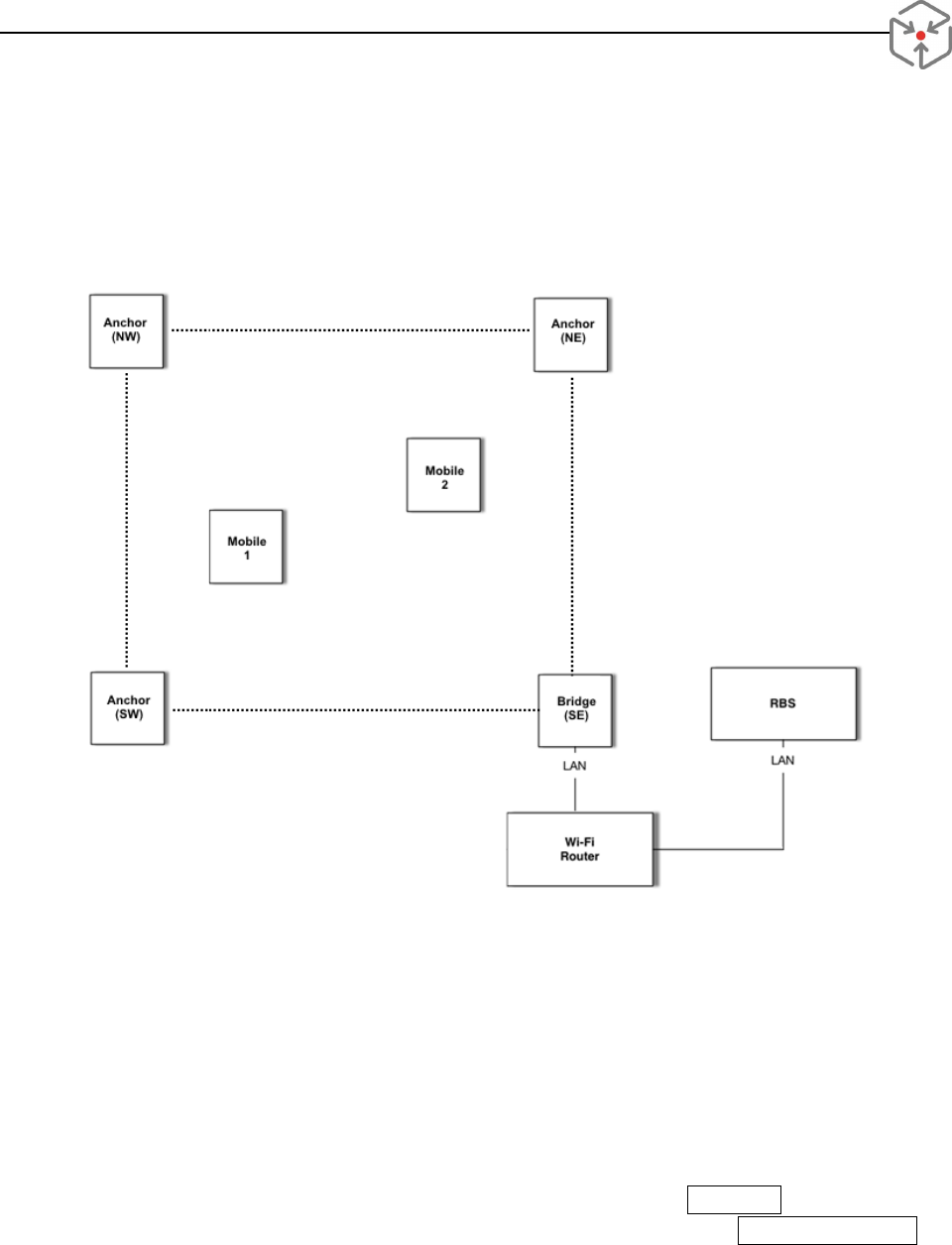
Figure 4 illustrates a setup using 4 anchors (including one bridge and multiple mobile nodes.
Connect the bridge labeled (SE) to the router’s LAN port
o To power the bridge via POE, connect Data In port of the POE injector to one of the
router’s LAN ports and the Data & Power Out port to the bridge’s LAN port.
o To power the bridge via USB, connect a USB power source to the micro-USB port of the
bridge. Connect the router’s LAN port and the bridge’s LAN port directly with an
Ethernet cable.
Power on the three A/M node labeled 'SW', 'NE', and 'NW'
o You should see a red LED blink a few times at about 1Hz when a node is powered on.
Mount anchors at the desired location and take notes of the MAC address and corresponding
coordinates (in mm)
o To minimize signal blockage, it is a good practice to mount anchors at elevated positions.
The default setting is 2m above the ground.
9/22/2015 RTLS DEVELOPMENT KIT QUICK START GUIDE
© 2015, Red Point Positioning Corp. Public 6
o All radio nodes have linear polarized antenna and therefore it is recommended to
mount them with the long side straight up or down (i.e., the RPP logo should be on the
top or bottom). Mounting the device sideways will degrade the system performance.
Figure 4 - Sample RTLS configuration
Step 4: Launching End User Console
Wait for a minute or so to allow all nodes to join the network
Connect the Windows computer to the Wi-Fi RTLS network
Launch EndUserConsole program (EUC)
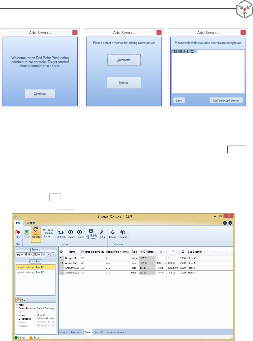
If it's the first time to run this program, a Welcome screen will show up, follow the prompt to
complete the setup
If it's not the first time, click on + on the top of the left panel, then follow the prompts
o When prompted to select a server selection method, click on Automatic
o Once server IP address appears, highlight the IP address, then click Add Selected Server
9/22/2015 RTLS DEVELOPMENT KIT QUICK START GUIDE
© 2015, Red Point Positioning Corp. Public 7
Figure 5 - EUC. Connecting to the server
Step 5: Setting Anchor Positions
Four (4) anchors should appear in the Console, including one bridge, and three fixed nodes
o If less than 4 anchors are shown in the list, wait for a few seconds and then click Refresh
o Note that only the last 5 digits of the MAC address are displayed
Anchor nodes have to be Bridge or Fixed types. The type of a node can be changed by double
clicking on it
Verify anchor locations. If the locations are incorrect,
1) manually enter the new locations
2) click Save to push the new anchor locations to the server
3) click on Refresh to update the screen
Figure 6 – EUC. Bridge with anchor nodes
9/22/2015 RTLS DEVELOPMENT KIT QUICK START GUIDE
© 2015, Red Point Positioning Corp. Public 8
By default, only a subset of node attributes are displayed in the data tab. To view other information of
the nodes, put the mouse over the title area and right click. A list of properties will show up in a pop-up
window, check the box next to the attribute you would like to view.
Step 6: Adding Mobile Nodes
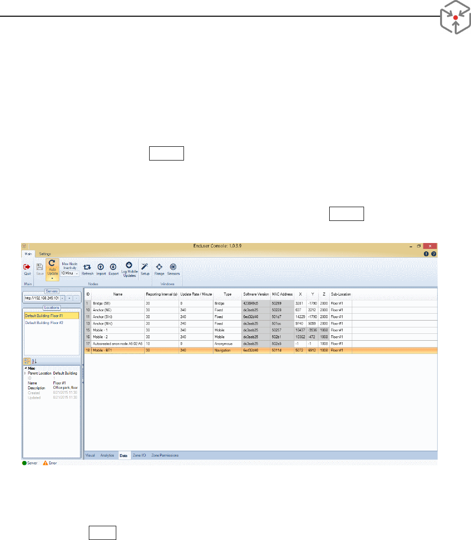
Power on one or more of the other nodes in the kit
Wait for 10 seconds, click Refresh to refresh the screen
All nodes in the kit should be pre-configured as Navigation node already. By default, their
positions are updating at 2Hz.
If some nodes are listed as Anonymous, change the node type to Mobile. Once the changes are
saved, node positions will start updating. You may need to click on Refresh to refresh the list
A node joins the server for the first time is assigned as Anonymous.
Figure 7 – EUC. Bridge, anchors, and mobile nodes
Step 6: Visualizing Node Locations
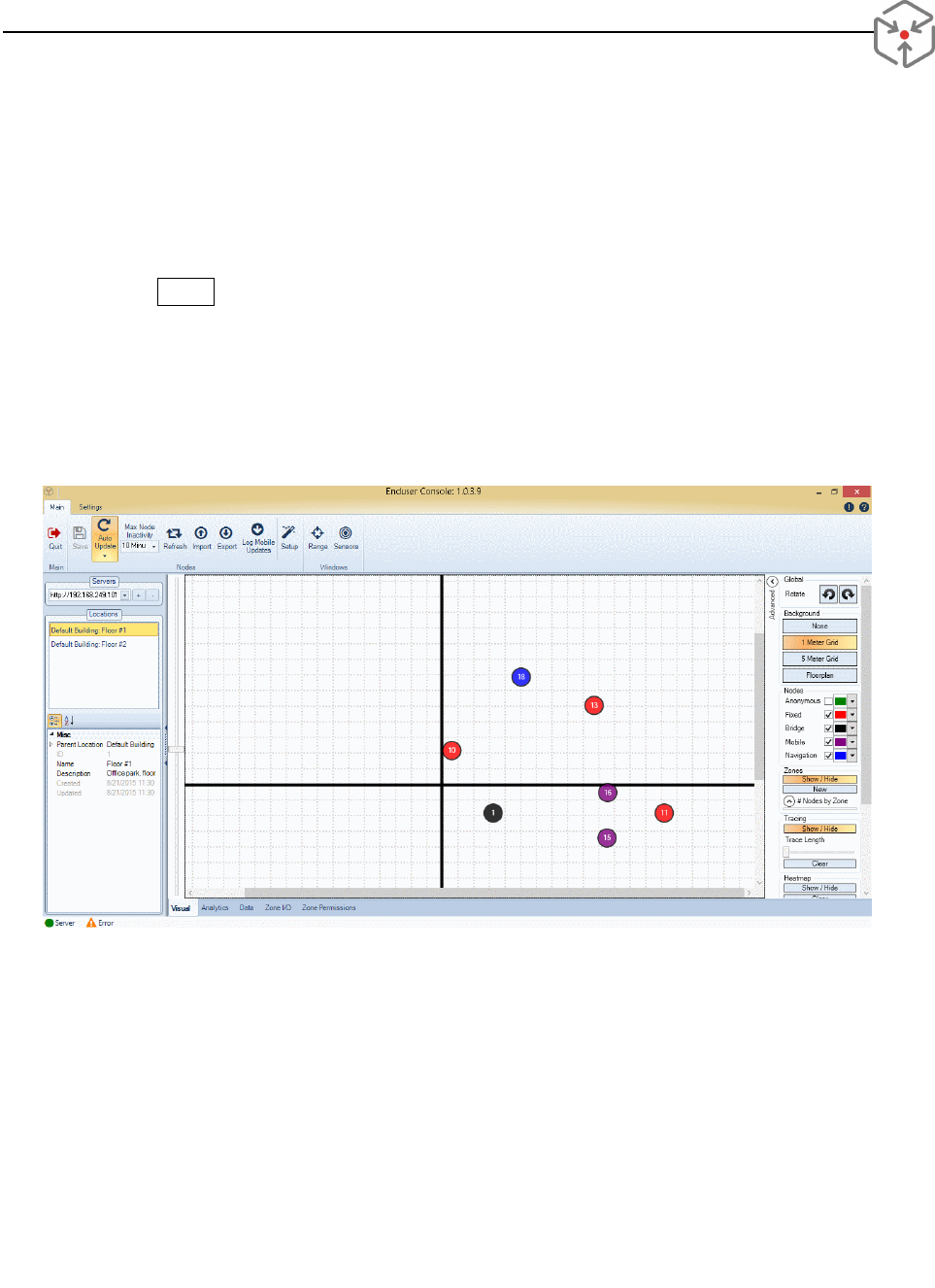
Click on the Visual tab
All nodes that have joined the network are displayed on the screen
Use the sliding bar on the left of the image to zoom, use the rotation buttons to rotate the
display
From the panel on the right, assign colors for different node types if you wish
Select the background
o You can insert a layout in the background if it is available as an image file. You may need
to manually adjust the scale, origin and orientation of the image
For using the EUC’s advanced features, please refer to the complete End User Console User Guide.
9/22/2015 RTLS DEVELOPMENT KIT QUICK START GUIDE
© 2015, Red Point Positioning Corp. Public 9
This COMPLETE the demo setup, you should be able to walk around with the mobile nodes and
observe the locations updated on the screen now.
3. After the Demonstration
Power off all the nodes and remove them from their mounting locations
Press the Power button of the RBS briefly and wait for the RBS to shut down
o A forced power off or unexpected power loss may corrupt the RBS software, therefore
Do NOT hold the power button down
Do NOT unplug the power before the RBS is completely shut down
Disconnect the Wi-Fi router and other devices
Recharge the radio nodes, if necessary
Figure 8 – EUC. Visual tab view
4. Regulatory Compliance
4.1. European Union
This equipment complies with the European Union Telecommunications Standard ETSI EN 302 065-
2 V1.1.1 (2014-04) for Ultra-Wideband Transmission Systems.
Cet équipement est conforme avec l'Union européenne sur les télécommunications norme ETSI EN
302 065-2 V1.1.1 (2014-04) pour Ultra-Wideband Transmission Systems

9/22/2015 RTLS DEVELOPMENT KIT QUICK START GUIDE
© 2015, Red Point Positioning Corp. Public 10
4.2. United States of America
This equipment complies with the FCC Rules Part 15, subpart F section 517 and Part C section 250
for Ultra-Wideband and Broadband devices respectively.
This device complies with part 15 of the FCC Rules. Operation is subject to the following two
conditions:
(1) This device may not cause harmful interference, and
(2) This device must accept any interference received, including interference that may cause
undesired operation.
Note: This equipment has been tested and found to comply with the limits for a Class B digital device,
pursuant to part 15 of the FCC Rules. These limits are designed to provide reasonable protection
against harmful interference in a residential installation. This equipment generates, uses and can
radiate radio frequency energy and, if not installed and used in accordance with the instructions,
may cause harmful interference to radio communications. However, there is no guarantee that
interference will not occur in a particular installation. If this equipment does cause harmful
interference to radio or television reception, which can be determined by turning the equipment off
and on, the user is encouraged to try to correct the interference by one or more of the following
measures:
- Reorient or relocate the receiving antenna.
- Increase the separation between the equipment and receiver.
- Connect the equipment into an outlet on a circuit different from that to which the receiver is
connected.
- Consult the dealer or an experienced radio/TV technician for help.
Caution: changes or modifications not expressly approved by the party responsible for
compliance could void the user's authority to operate the equipment.
4.3. Canada
The device RPP-XRN-V4 is licensed to meet Industry Canada (IC) Radio Standards Specification
RS-220 Issue 1, March 2009, Devices Using Ultra-Wideband (UWB) Technology. In particular,
(1) Section 5.2: Ultra-Wideband indoor communication devices; and
(2) Section 5.3: Ultra-Wideband hand-held communication devices

9/22/2015 RTLS DEVELOPMENT KIT QUICK START GUIDE
© 2015, Red Point Positioning Corp. Public 11
This device complies with Industry Canada’s license-exempt RSSs. Operation is subject to the
following two conditions:
(1) The device may not cause interference; and
(2) This device must accept any interference, including interference that may cause undesired
operation of the device.
le dispositif RPP-XRN-V4 est autorisé pour répondre à Industrie Canada (IC) les normes
radioélectriques RS-220 Issue 1, Mars 2009, des dispositifs utilisant ultra-wideband (UWB). En
particulier,
(1) L'article 5.2: bande ultra-large de dispositifs de communication à l'intérieur; et
(2) L'article 5.3: Ultra-Wideband appareils de communication portatifs
Cet appareil est conforme aux CNR exempts de licence d'Industrie Canada. Son fonctionnement est
soumis aux deux conditions suivantes:
(1) Le dispositif ne doit pas causer d'interférences; et
(2) Ce dispositif doit accepter toute interférence, y compris les interférences qui peuvent
entraîner un mauvais fonctionnement de l'appareil.
5. Contact Us
Contact us directly for support:
Redpoint Positioning Corporation
20 Webster Street, Suite 411
Brookline, MA 02446, USA
Web: http://redpointpositioning.com/support/
Email: support@redpointpositioning.com
Phone: +1(617)207-4096