EPIC W GEMINI Operation Guide V7.1 955 0159 Rev G RED PS,
2019-02-20
: Red 955-0159 V7.1 Rev-G Red Ps, Epic-W Gemini Operation Guide 955-0159_v7.1 Rev-G RED PS, EPIC-W GEMINI Operation Guide 955-0159_v7.1
Open the PDF directly: View PDF ![]() .
.
Page Count: 267 [warning: Documents this large are best viewed by clicking the View PDF Link!]
- EPIC-W GEMINI Operation Guide
- Table of Contents
- CHAPTER 1: Product Introduction
- CHAPTER 2: Camera System Components
- CHAPTER 3: Basic Operations
- CHAPTER 4: Basic Menus and Controls
- CHAPTER 5: Advanced Menus
- CHAPTER 6: Sensor Calibration
- CHAPTER 7: Audio System
- CHAPTER 8: Timecode, Genlock, Multi-Camera Setup
- CHAPTER 9: Upgrade Camera Firmware
- CHAPTER 10: Camera System Maintenance
- CHAPTER 11: Troubleshoot Your Camera
- APPENDIX A: Technical Specifications
- APPENDIX B: Mechanical Drawings
- APPENDIX C: Input/Output Connectors
- APPENDIX D: Lens Mounts and Lenses
- APPENDIX E: Default Key Functions
- APPENDIX F: Menu Map
V7.1
RED.COM
EPIC-W GEMINI
OPERATION GUIDE

Table of Contents 2
Disclaimer 4
Copyright Notice 4
Trademark Disclaimer 4
Translation Disclaimer 4
Compliance Statements 4
Safety Instructions 6
Battery Storage and Handling 7
Shipping Disclaimer 8
CHAPTER 1: Product Introduction 9
Read Before You Shoot 9
R3D File Format and REDCODE 10
Shoot For Video and Stills 10
Post Production 11
Post Production with REDCINE-X PRO 11
HDRX and MAGIC MOTION 12
Additional Resources 12
CHAPTER 2: Camera System Components 13
Additional Resources 13
BRAIN 13
RED MINI-MAG System 18
Expanders 19
DSMC2 Power Modules 25
RED Batteries and Chargers 29
Displays and Electronic Viewfinders 30
LCD/EVF Adaptors 35
Camera Control Modules 36
Lens Mounts 41
Interchangeable OLPFs 42
Rails, Mounts, Tactical Gear, and Cables 43
CHAPTER 3: Basic Operations 44
Power Operations 44
Configure Your Camera 47
Interchangeable OLPF System 53
Use a Tripod or Monopod 54
Video Monitor Outputs 55
Record 56
CHAPTER 4: Basic Menus and Controls 58
GUI Menu Introduction 58
Upper Status Row (Basic Menu) 59
C OPYR I GHT © 20 19 R ED. C OM , LLC 955- 0159_V 7. 1, R EV -G | 2
EPIC-W GEMINI OPERATION GUIDE
TABLE OF CONTENTS
Live Action Area 63
Lower Status Row 65
Navigation Controls 72
CHAPTER 5: Advanced Menus 81
Access the Advanced Menus 81
Image Menu 81
Monitoring Menu 90
Overlays Menu 96
Power Menu 105
Playback 108
Media Menu 113
Presets Menu 114
Settings Menu 117
CHAPTER 6: Sensor Calibration 159
Check Noise Profile 159
When to Calibrate Sensor 159
Calibrate Sensor: Manual Calibration 160
Calibrate Sensor: Auto Calibration 162
Calibration Map Naming Conventions 164
Calibration Management 165
Calibration Map Actions 165
Export and Import Calibration Maps 165
CHAPTER 7: Audio System 166
Audio Overview 166
Set Up Audio 166
Control 167
Mix 170
Audio Output Options 170
Audio Meter (VU Meter) 170
Audio During Playback 171
Record Audio in Varispeed Mode 172
CHAPTER 8: Timecode, Genlock, Multi-
Camera Setup 174
Timecode 174
Genlock 177
Master/Slave Operation 179
Set Up Stereo/3D Configuration 184
Camera Array 185
Motion Control (MoCo) 186
Compatible Timecode Devices 188

Compatible Genlock Devices 188
CHAPTER 9: Upgrade Camera Firmware 189
Verify Current Camera Firmware 189
Upgrade Camera Firmware 189
CHAPTER 10: Camera System
Maintenance 191
BRAIN and Accessory Exterior Surfaces 191
Clean EVF Screen 192
Clean LCD Screens 192
Water Damage 193
Adjust Back Focus 194
CHAPTER 11: Troubleshoot Your Camera 195
Perform a Stress Test 195
General Troubleshooting 196
Error Messages 203
Media Bay and RED MINI-MAG Issues 208
Back Focus Lock (Lock Sensor) 209
APPENDIX A: Technical Specifications 211
EPIC-W 5K S35 Technical Specifications 211
APPENDIX B: Mechanical Drawings 214
EPIC-W 5K S35 BRAIN 214
APPENDIX C: Input/Output Connectors 219
DSMC2 Base Expander 220
DSMC2 V-Lock I/O Expander 221
DSMC2 REDVOLT Expander 222
DSMC2 Jetpack Expander 223
DSMC2 Jetpack-SDI Expander 224
DSMC2 Production Module (V-Lock) 225
DSMC2 Tactical Top Plate 226
DSMC2 Production Top Plate 226
Record/Monitor Out Ports 227
Communication Ports 230
Audio Ports 241
Power Ports 243
APPENDIX D: Lens Mounts and Lenses 248
Lens Mounts 248
Lenses 252
APPENDIX E: Default Key Functions 264
Default Keys 264
APPENDIX F: Menu Map 267
C OPYR I GHT © 2 01 9 RE D.C OM , LLC 955- 0159_V 7. 1, R EV -G | 3
EPIC-W GEMINI OPERATION GUIDE

DISCLAIMER
RED ® has made every effort to provide clear and accurate
information in this document, which is provided solely for the user’s
information. While thought to be accurate, the information in this
document is provided strictly “as is” and RED will not be held
responsible for issues arising from typographical errors or user’s
interpretation of the language used herein that is different from that
intended by RED. All safety and general information is subject to
change as a result of changes in local, federal or other applicable
laws.
RED reserves the right to revise this document and make changes
from time to time in the content hereof without obligation to notify any
person of such revisions or changes. In no event shall RED, its
employees or authorized agents be liable to you for any damages or
losses, direct or indirect, arising from the use of any technical or
operational information contained in this document.
This document was generated on 2/18/2019. To see earlier versions
of this document, submit a Support ticket at https://support.red.com.
For comments or questions about content in this document, send a
detailed email to OpsGuides@red.com.
COPYRIGHT NOTICE
COPYRIGHT© 2019 RED.COM, LLC.
All trademarks, trade names, logos, icons, images, written material,
code, and product names used in association with the accompanying
product are the copyrights, trademarks, or other intellectual property
owned and controlled exclusively by RED.COM, LLC. For a
comprehensive list, see www.red.com/trademarks.
TRADEMARK DISCLAIMER
All other company, brand, and product names are trademarks or
registered trademarks of their respective holders. RED has no
affiliation to, is not associated with or sponsored by, and has no
express rights in third-party trademarks. Adobe and Adobe Premiere
Pro are registered trademarks of Adobe Systems Incorporated. AJA
is a registered trademark of AJA Video Systems, Inc. Cooke and S4/i
are registered trademarks of Cooke Optics Limited. DaVinci is a
registered trademark of Blackmagic Design in the U.S. and other
countries. Distagon, Makro- Planar, and Otus are registered
trademarks of Carl Zeiss AG. Fujinon is a registered trademark of
FUJIFILM CORPORATION. HDMI is a registered trademark of HDMI
Licensing LLC in the United States and other countries. Leica is a
registered trademark of Leica Microsystems. Loctite is a registered
trademark of Henkel AG & Company KGaA. Nikkor and Nikon are
registered trademarks of Nikon Corporation. Canon is a registered
trademark of Canon, U.S.A. Apple, Macintosh, Final Cut Pro, and
QuickTime are registered trademarks of Apple Inc. in the U.S. and
other countries. Windex is a registered trademark of S. C. Johnson &
Son, Inc. Windows is a registered trademark of Microsoft Corporation.
Sony is a registered trademark of Sony Corporation. TORX is a
registered trademark of Acument Intellectual Properties, LLC in the
United States or other countries. IOS is a registered trademark of
Cisco in the U.S. and other countries. Avid is a registered trademark
of Avid Technology, Inc. DaVinci Resolve is a registered trademark of
Blackmagic Design in the U.S. and other countries. EDIUS Pro is a
registered trademark of Grass Valley. Vegas Pro is a registered
trademark of Sony Creative Software. IDX is a registered trademark
of IDX Company, Ltd.
C OPYR I GHT © 2 01 9 RE D.C OM , LLC 955- 0159_V 7. 1, R EV -G | 4
EPIC-W GEMINI OPERATION GUIDE
TRANSLATION DISCLAIMER
This document was originally prepared in English, and any translations
are provided for convenience only. While reasonable efforts were
made to provide accurate translations, RED will not be held
responsible for any errors, omissions, or ambiguities.
COMPLIANCE STATEMENTS
INDUSTRIAL CANADA EMISSION COMPLIANCE STATEMENTS
This device complies with Industry Canada license- exempt RSS
standards RSS 139 and RSS 210. Operation is subject to the following
two conditions: (1) this device may not cause interference, and (2) this
device must accept any interference, including interference that may
cause undesired operation of the device.
This Class B digital apparatus complies with Canadian ICES-003.
Le présent appareil est conforme aux CNR d’Industrie Canada
applicables aux appareils radio exempts de licence. L’exploitation est
autorisée aux deux conditions suivantes : (1) l’appareil ne doit pas
produire de brouillage, et (2) l’utilisateur de l’appareil doit accepter
tout brouillage radioélectrique subi, même si le brouillage est
susceptible d’en compromettre le fonctionnement.Cet appareil
numérique de la classe B est conforme à la norme NMB-003 du
Canada.
FEDERAL COMMUNICATIONS COMMISSION (FCC)
STATEMENTS
This equipment has been tested and found to
comply with the limits for a Class B digital
device, pursuant to part 15 of the FCC Rules.
These limits are designed to provide
reasonable protection against harmful
interference in a residential installation. This
equipment generates, uses and can radiate
radio frequency energy and, if not installed and used in accordance
with the instructions, may cause harmful interference to radio
communications. However, there is no guarantee that interference will
not occur in a particular installation. If this equipment does cause
harmful interference to radio or television reception, which can be
determined by turning the equipment off and on, the user is
encouraged to try to correct the interference by one or more of the
following measures:
Reorient or relocate the receiving antenna.
Increase the separation between the equipment and receiver.
Connect the equipment into an outlet on a circuit different from
that to which the receiver is connected.
Consult the dealer or an experienced radio/TV technician for
help.
In order to maintain compliance with FCC regulations, shielded cables
must be used with this equipment. Operation with non-approved
equipment or unshielded cables is likely to result in interference to
radio and TV reception. The user is cautioned that changes and
modifications made to the equipment without the approval of
manufacturer could void the users authority to operate this equipment.
NOTE: This device complies with Part 15 of the FCC Rules.
Operations subjected to the following two conditions (1) this device
may not cause harmful interference, and (2) this device must accept
any interference received, including that may cause undesirable
interference.

CAUTION: Exposure to Radio Frequency
Radiation.
The device shall be used in such a manner that the potential for
human contact is minimized.
This equipment complies with FCC radiation exposure limits set forth
for an uncontrolled environment. This equipment should be installed
and operated with a minimum distance of 20 cm between the radiator
and your body.
CAUTION: Regulations of the FCC and FAA
prohibit airborne operation of radio- frequency
wireless devices because there signals could
interfere with critical aircraft instruments.
CAUTION: If the device is changed or modified
without permission from RED, the user may void
his or her authority to operate the equipment.
AUSTRALIA AND NEW ZEALAND STATEMENTS
RED declares that the radio equipment described in this document
comply with the following international standards.
IEC 60065 – Product Safety
ETSI EN 300 328 – Technical requirement for radio equipment
RED declares digital devices described in this document comply with
the following Australian and New Zealand standards.
AS/NZS CISPR 22 – Electromagnetic Interference
AS/NZS 61000.3.2 – Power Line Harmonics
AS/NZS 61000.3.3 – Power Line Flicker
JAPAN STATEMENTS
This is a Class B product based on the
standard of the Voluntary Control Council
for Interference (VCCI) for information
technology equipment. If this equipment is
used near a radio or television receiver in a
domestic environment, it may cause radio
interference. Install and use the equipment
according to the instruction manual.
C OPYR I GHT © 2 01 9 R ED. C OM , LLC 95 5- 01 59 _V 7. 1, R EV- G| 5
EPIC-W GEMINI OPERATION GUIDE
GITEKI CERTIFICATION
This equipment contains specified radio equipment that has been
certified to the Technical Regulation Conformity Certification under the
Radio Law.
EUROPEAN UNION COMPLIANCE STATEMENTS
RED declares that the radio
equipment described in this
document comply with the
R&TTE Directive (1999/5/EC)
issued by the Commission of
the European Community.
Compliance with this directive implies conformity to the following
European Norms (in brackets are the equivalent international
standards).
EN 60065 (IEC 60065) – Product Safety
ETSI EN 300 328 Technical requirement for radio equipment
ETSI EN 301 489 General EMC requirements for radio
equipment.
INFORMATION
Products with the CE marking comply with the EMC Directive
(2004/108/EC) and the Low Voltage Directive (2006/95/EC) issued by
the Commission of the European Community. Compliance with these
directives implies conformity to the following European Product Family
Standards.
EN 55022 (CISPR 22) – Electromagnetic Interference
EN 55024-1 (CISPR 24) – Electromagnetic Immunity
EN 61000-3-2 (IEC610000-3-2) – Power Line Harmonics
EN 61000-3-3 (IEC610000) – Power Line Flicker
EN 60065 (IEC60065) – Product Safety
WASTE ELECTRICAL AND ELECTRONIC EQUIPMENT (WEEE)
The Waste Electrical and Electronic
Equipment (WEEE) mark applies only to
countries within the European Union (EU)
and Norway. This symbol on the product and
accompanying documents means that used
electrical and electronic products should not
be mixed with general household waste. For
proper treatment, recovery and recycling,
please take this product to designated
collection points where it will be accepted
free of charge. Alternatively, in some
countries you may be able to return your
products to your local retailer upon purchase of an equivalent new
product.
Disposing of this product correctly will help save valuable resources
and prevent any potential negative effects on human health and the
environment, which could otherwise arise from inappropriate waste
handling. Please contact your local authority for further details of your
nearest designated collection point. Penalties may be applicable for
incorrect disposal of this waste, in accordance with you national
legislation.
For business users in the European Union, if you wish to discard
electrical and electronic equipment, please contact your dealer or
supplier for further information.
USAGE RESTRICTIONS FOR PRODUCTS THAT INCORPORATE
RED COMMAND PROTOCOL
Products that fall into this category are denoted
by inclusion of the Class 2 identifier symbol
(exclamation mark in a circle) accompanying
the CE Mark on the products regulatory label,
example to the left.
FRANCE
Usage Restrictions - Geographic Area Where Restriction Applies :
France
For mainland France
2.400 - 2.4835 GHz (Channels 1-16) authorized for indoor use
2.400 - 2.454 GHz (Channels 1-10) authorized for outdoor use
Restrictions d’utilisation - Zone géographique où les restrictions
s’appliquent : France
Pour la France métropolitaine
2.400 - 2.4835 GHz (Canaux 1 à 16) autorisé en usage intérieur
2.400 - 2.454 GHz (Canaux 1 à 10) autorisé en usage extérieur
NORWAY
This subsection does not apply for the geographical area within a
radius of 20 km from the centre of Ny-Ålesund
Dette gjelder ikke for det geografiske området innenfor en radius av
20 km fra sentrum av Ny-Ålesund
RESPONSIBLE PARTY
RED Digital Cinema
34 Parker
Irvine, CA 92618
USA
C OPYR I GHT © 2 01 9 R ED. C OM , LLC 95 5- 01 59 _V 7. 1, R EV- G| 6
EPIC-W GEMINI OPERATION GUIDE
SAFETY INSTRUCTIONS
DO NOT use the camera or accessories near water. Avoid
exposing your camera to moisture. The unit is not waterproof, so
contact with water could cause permanent damage to the unit as
well as electric shock and serious injury to the user. DO NOT use
the camera in the rain or under other conditions with high
moisture without appropriate protection, and immediately remove
power source if camera or accessories are exposed to moisture.
WARNING: To reduce the risk of fire or electric
shock, do not expose the camera to rain or
moisture.
DO NOT expose the camera to laser beams, as laser beams may
damage the sensor.
DO NOT expose your camera to excessive vibration or impact
(shock). Be careful not to drop your camera. Internal mechanisms
may be damaged by severe shock. Mechanical alignment of
optical elements may be affected by excessive vibration.
ELECTROMAGNETIC INTERFERENCE: The use of devices using
radio or other communication waves may result in the malfunction
or interference with the unit and/or with audio and video signals.
Clean only using a dry cloth. When cleaning your camera,
remember that it is not waterproof and moisture can damage
electronic circuitry. DO NOT rinse or immerse any element of the
camera, lens or other accessory, keep them dry at all times. DO
NOT use soaps, detergents, ammonia, alkaline cleaners, and
abrasive cleaning compounds or solvents. These substances may
damage lens coatings and electronic circuitry.
Maintain sufficient ventilation—DO NOT block any ventilation
openings or obstruct cooling fan airflow.
CAUTION: Proper camera ventilation requires a
minimum 0.5" (1.25 cm) clearance between the
camera ventilation openings and external
surfaces. Verify that objects that can block the fan
intake and exhaust ports do not impede airflow.
Failure to permit adequate airflow may result in
overheating of the camera, degraded operation
and in extreme situations, damage to the camera.
DO NOT operate or store near any heat sources such as
radiators, heat registers, stoves, or any other apparatus that
produce heat. Store in a protected, level and ventilated place.
Avoid exposure to temperature extremes, damp, severe vibration,
strong magnetic fields, direct sunlight or local heat sources during
storage. Remove any batteries from the camera before storage.
Recommended storage and usage temperatures for your camera,
lenses and other accessories are:
Operating range: 0°C to 40°C (32°F to 104°F)
Storage range: –20°C to 50°C (–4°F to 122°F)
If there are any performance issues with your camera or
accessories when operating within this temperature range, submit
a Support ticket at https://support.red.com.
Modules, expanders, and lens mounts are NOT HOT
SWAPPABLE, meaning you cannot remove or install these items
while the camera is turned on. Before installing or removing these
items, you MUST turn off the camera. Failure to do so may result
in damage to the item or camera that is not covered under
warranty.
DO NOT bypass the third prong of the grounding-type plug on the
power cord of the included power adaptor. A grounding-type plug
has two blades and a third “grounding” prong. The third prong is
provided for your safety. A grounding-type plug shall be
connected to an outlet with a protective earthen connection. If the
grounding-type plug does not fit into your outlet, do not attempt to
modify the plug or outlet, consult a qualified electrician.
Protect all power cords from being pinched, walked on or driven
over by a vehicle. Replace any power cords suspected of
sustaining damage due to crushing or other forms physical
damage.
Products marked with this symbol are class 2
devices. These devices are not provided with a
grounding type plug.
CAUTION: The power cord plug for the included
power adaptor is used as the power disconnect.
To disconnect all power from the power adaptor,
unplug the power cord plug from the wall outlet.
During use, the power cord plug should remain
easily accessible at all times.
Lithium-ion batteries may be subject to special handling
requirements pursuant to federal and local laws. Refer to specific
shipping instructions included with your battery regarding proper
transport of your battery. Do not handle your battery if it is
damaged or leaking. Disposal of batteries must be in accordance
with local environmental regulations. For example, California law
requires that all rechargeable batteries must be recycled by an
authorized recycle center. Storing batteries fully charged or in
high temperature conditions may permanently reduce the life of
the battery. Available battery capacity may also be temporarily
lessened after storage in low temperature conditions.
C OPYR I GHT © 2 01 9 R ED. C OM , LLC 95 5- 01 59 _V 7. 1, R EV- G| 7
EPIC-W GEMINI OPERATION GUIDE
WARNING: DO NOT expose the battery to
excessive heat.
WARNING: Danger of explosion if an incorrect
battery is charged with the RED Charger or is
used to power the camera and accessories.
Replace only with the same or equivalent type
battery.
CAUTION: Refer all service and repair to qualified
RED service personnel. To reduce the risk of
electric shock, and damage to the camera or
accessories, DO NOT attempt to perform any
servicing other than any procedures that are
recommended in the operating instructions.
INDOOR USE ONLY: This device is designed for
use indoors only.
BATTERY STORAGE AND HANDLING
WARNING: Failure to read, understand, and
follow these instructions may result in overheating,
chemical leakage, smoke emission, fire, or other
potentially harmful results.
Always follow proper battery handling and storage practices.
Improper handling and/or failure to abide by proper storage
instructions may cause permanent damage to batteries, or
degrade battery charge holding capacity. Improper handling
practices or failure to comply with instructions may also put you at
risk.
Lithium-Ion batteries, like the REDVOLT®, REDVOLT-V,
REDVOLT XL, and RED BRICK®, self-discharge over time. When
storing for long periods of time, store batteries separately from the
camera or charger and remember to charge batteries to a
capacity level of 40% to 60%. If batteries will be stored for long
periods of time, RED recommends that you check the charge
level at least once every six (6) months, and recharge batteries to
a capacity level of 40% to 60%.
When not in use, remove the battery from the camera or charger
and store the battery in a cool, dry place. Avoid extreme hot
temperatures (such as inside a hot car), corrosive gas, and direct
sunlight. The optimal storage temperature for batteries is between
–20°C to 20°C (–4°F to 68°F).
WARNING: Batteries stored in a discharged state
for long periods of time may self-discharge and
lose the ability to hold a charge.
WARNING: If recharging operation fails to
complete even when a specified recharging time
has elapsed, immediately stop further recharging.
DO NOT store batteries in a fully charged state for extended DO
NOT store batteries in a fully charged state for extended periods
of time.
DO NOT store batteries in a fully discharged state for extended
periods of time.
DO NOT store batteries in the camera, in a camera module, or in
a charger for extended periods of time.
DO NOT use batteries for purposes other than their intended use.
DO NOT store batteries in extreme hot or cold temperatures.
DO NOT store batteries in direct sunlight.
DO NOT use third-party chargers with your RED batteries.
DO NOT disassemble or modify the battery.
DO NOT overcharge batteries. Overcharging may increase
internal temperature beyond the recommended limits and cause
permanent damage to the battery.
DO NOT connect the positive (+) and negative (–) terminals to a
metal object such as a wire.
DO NOT transport or store the battery together with metal objects
such as jewelry, hairpins, etc. as they may generate heat if they
come into contact with the battery.
DO NOT discard the battery into fire or heat.
DO NOT store, use, or recharge the battery near a heat source
such as a fire or a heater.
DO NOT allow the battery to get wet.
DO NOT pierce the battery with pointed or other sharp objects.
DO NOT step on, throw, or strike the battery with a hammer.
DO NOT use a battery that appears to be deformed or damaged.
DO NOT directly solder the battery.
DO NOT put the battery into a microwave oven or a pressurized
container.
DO NOT use or subject the battery to intense sunlight or hot
temperatures such as in a car in hot weather.
DO NOT use it in a location where static electricity may be
present.
DO NOT exceed the recharging temperature range of 0˚C to 40˚C
(32˚F to 104˚F).
RED recommends that you only use RED chargers to recharge
RED batteries.
Store the battery in a location where children cannot reach it.
If the battery leaks or gives off a bad odor, discontinue use
immediately.
C OPYR I GHT © 2 01 9 R ED. C OM , LLC 95 5- 01 59 _V 7. 1, R EV- G| 8
EPIC-W GEMINI OPERATION GUIDE
If the battery gives off an odor, generates heat, becomes
discolored or deformed, or in any way appears abnormal during
use, recharging or storage, immediately remove it from the
equipment or battery charger and discontinue use.
If electrolyte begins leaking from the battery and comes into
contact with your skin or clothing, immediately wash it away with
running water. Failure to do this may result in skin inflammation.
If the battery leaks and the electrolyte reaches the eyes, do not
rub them. Instead, rinse the eyes with clean running water and
immediately seek medical attention. Failure to do this may result in
eye injury.
If you find discoloration, a bad odor due to leakage, overheating
and/or other irregularities when using the battery for the first time,
submit a Support ticket at https://support.red.com.
NOTE: For more information regarding RED
battery charging and instructions for care, refer to
our Terms and Conditions.
SHIPPING DISCLAIMER
Shipment of Lithium Ion cells and batteries is subject to national and
international shipping requirements. A Class 9 Certified shipper is
required to transport these products within the United States.
REDVOLT, REDVOLT-V, REDVOLT XL, and RED BRICK batteries are
considered Dangerous Goods. Other products such as REDVOLT AA
and RED Li 7.2V batteries may also be classified as Dangerous Goods
when purchased in bulk. Applicable laws prohibit the shipping of
batteries that are physically damaged. We urge you to look into the
formal rules and regulations of shipping Class 9 Dangerous Goods
prior to preparing your shipment. For more information on these
regulations, visit www.iata.org and www.dot.gov.
For more information, see our FAQs for Dangerous Goods (Regulated
Items).

C OPYR I GHT © 2 01 9 R ED. C OM , LLC 955- 0159_V 7. 1, R EV -G |9
EPIC-W GEMINI OPERATION GUIDE
CHAPTER 1:
PRODUCT INTRODUCTION
The RED EPIC-W® 5K S35 features the GEMINI® 5K S35 sensor, RED’s highest-sensitivity sensor to date. The EPIC-
W 5K S35 is a powerful, dual sensitivity camera that offers the ability to shoot in either Low Light or Standard modes.
The EPIC-W 5K S35 offers cleaner, less-noisy images in low-light conditions as well as improved performance in
shadows.
Capable of shooting motion and stills at 5K 2.4:1 at up to 120 frames per second (fps), or 5K Full Format at 96 fps, the
EPIC-W 5K S35 delivers high frame rates at an S35 format.
As a member of the DSMC2® camera lineup, the EPIC-W 5K S35 benefits from the advanced modularity of the RED
ecosystem. The camera features cable-free peripherals, integrated mounting plate, wireless control, and compatibility
with a growing number of DSMC2 modules and accessories. EPIC-W 5K S35 also supports interchangeable OLPFs
and lens mounts—empowering you to make the most of all of your S35 compatible PL, Nikon, Canon, and Leica
lenses.
This guide is for EPIC-W 5K S35 only. This section introduces the imaging capabilities and advanced features of the
EPIC-W 5K S35 system. For information about other cameras, go to RED Downloads at www.red.com/downloads.
The EPIC-W 5K S35 system includes the following cameras:
SENSOR TYPE CAMERA
GEMINI 5K S35 EPIC-W 5K S35
NOTE: The camera itself does not have a DC IN power port. A port expander or power module is required to power
the camera. To construct a working configuration for any camera, RED recommends an expander, battery, lens mount,
display, and media.
READ BEFORE YOU SHOOT
Read this operation guide carefully and in its entirety before assembling or operating your camera or other RED
accessories. In addition to this document, RED offers the following operation guides for the camera system:
DSMC Power Operation Guide
DSMC Media Operation Guide
To download RED operation guides, go to RED Downloads at www.red.com/downloads.

R3D FILE FORMAT AND REDCODE
All videos and frames are recorded to the R3D® file format. The R3D file format was developed by RED to provide an
efficient and manageable RAW video data format that promotes advanced post production editing capabilities. In the
R3D file format, the digital image received from the sensor is formatted as a pixel-defect corrected (but in all other
aspects unprocessed) 16-bit per pixel RAW data frame. Each RAW frame, or sequence of RAW frames in a clip, is
compressed using a proprietary wavelet based REDCODE® RAW compression, then stored to a RED MINI-MAG®.
RAW data is recorded independently of any RGB domain color processing such as ISO, White Balance, or other RGB
color space settings. Instead, color parameters are saved as reference metadata; that is, color is not burned into the
recorded RAW data. This recording technique promotes flexibility in RGB color processing, which can be deferred to
post production or adjusted in the field, without affecting the recorded RAW data image quality or dynamic range.
REDCODE is a visually lossless, wavelet-based compression codec that reduces R3D RAW files into a manageable
size, allowing longer recording times on media. The ability to compress RAW data is one of the significant
technologies that RED has brought to the industry.
For more information, see the DSMC Media Operation Guide, available at www.red.com/downloads.
NOTE: REDCINE-X PRO® can create and export .RMD “Look” files which may then be imported as camera monitor
path color processing presets. This information is stored as reference metadata, so that these color processing
choices can be the default values used in post production. For more information, go to "Looks" on page115.
SHOOT FOR VIDEO AND STILLS
High resolution video, such as the digital footage captured by the camera, has surpassed the detail necessary to
produce professional full-sized prints. Because of the ability to record at high frame rates and resolution, the camera is
ideally suited to capture video and still images, simultaneously.
The camera is equipped with a Stills mode that makes it easier to capture stunning images. With presets optimized for
stills and Swipe-Up Shortcuts for the RED Touch display, switching from Motion mode to Stills mode is seamless.
Using REDCINE-X PRO, or other editing applications supporting the RED SDK, you can pull full resolution still images
from R3D files.
C OPYR I GHT © 2 01 9 R ED. C OM , LLC 955- 0159_V 7. 1, R EV -G | 10
EPIC-W GEMINI OPERATION GUIDE

POST PRODUCTION
NOTE: Third-party applications may have limited compatibility with R3D files. Third-party developers must use the
most recent R3D SDK to offer compatibility with the latest RED firmware.
Many non-linear editing systems (NLEs) can open and edit RED footage. Each NLE version may have specific
compatibility requirements, such as camera firmware version or camera type. Before shooting, check all compatibility
requirements.
The following programs can be used to open and/or edit R3D files:
REDCINE-X PRO: RED's proprietary NLE. Download REDCINE-X PRO from www.red.com/downloads.
Adobe Photoshop: Can open .R3D files. Requires you to download the RED Adobe Photoshop Installer from
www.red.com/downloads.
Adobe Premiere Pro: For more information on compatibility, go to the RED Support site at
https://support.red.com.
Avid Media Composer
DaVinci Resolve
Edius Pro
Final Cut Pro 7: Requires you to download the RED Apple Workflow Installer from www.red.com/downloads.
Final Cut Pro X: Requires you to download the RED Apple Workflow Installer from www.red.com/downloads.
Vegas Pro
POST PRODUCTION WITH REDCINE-X PRO
REDCINE-X PRO is a professional one-light coloring toolset, equipped with an integrated timeline and a post effects
software collection that provides the ideal environment to review recorded footage, edit metadata, organize projects,
and prepare your R3D files. Use either REDCINE-X PRO or a compatible third-party non-linear editing (NLE) application
to edit R3D files.
RED TETHER, included in REDCINE-X PRO, allows you to record footage from your camera directly to a computer or
an external drive. Using tethering bypasses the need to record to an SSD and offload to a computer later, saving you
time. The latest version of REDCINE-X PRO and the REDCINE-X PRO Operation Guide are available for download at
RED Downloads at www.red.com/downloads.
NOTE: RED TETHER is included in REDCINE-X PRO build 35 or later.
NOTE: RED TETHER requires a GIG-E port, which is available on the DSMC2 Jetpack-SDI Expander, DSMC2
REDVOLT Expander, and DSMC2 Production Module. For more information, go to "Input/Output Connectors" on
page219.
C OPYR I GHT © 2 01 9 R ED. C OM , LLC 955- 0159_V 7. 1, R EV -G | 11
EPIC-W GEMINI OPERATION GUIDE

HDRX AND MAGIC MOTION
HDRX
HDRX® extends dynamic range up to six (6) stops by simultaneously capturing two (2) images of identical resolution
and frame rate. The first image is a normally exposed track (A-track), while the second is an underexposed track (X-
track) with an exposure value that reflects the additional stops of highlight protection. These tracks are “motion-
conjoined” during recording, leaving no time gap between the two (2) exposures. This is different from traditional
alternating exposures, which have small gaps between tracks, producing unwanted motion tracks.
MAGIC MOTION
MAGIC MOTION is a post production method that combines two (2) HDRX tracks to create an image with both natural
motion blur (from the A-track) and sharper reference (the X-track). MAGIC MOTION produces an image with an
extraordinary dynamic range that is not available with any other motion capture camera.
Shooting at 24 fps with a 180° (1/48 sec) shutter on traditional film or digital cameras produces motion blur throughout,
which is not the way the human eye observes motion. For example, ask someone to swing their arm. What you would
observe in a traditional recording of this action is constant motion blur until the arm stops. However, what your eye
sees is both motion blur and a sharper reference of the arm throughout the motion path. MAGIC MOTION creates an
image that matches the natural motion observed by the human eye.
ADDITIONAL RESOURCES
The following resources offer additional information about RED, the DSMC system, and the RED community:
RED.com: Check the official RED website for the latest information about RED products.
RED Learn Articles: RED offers in-depth technical articles about RED cameras, post-production, and digital
cinematography.
RED Downloads: Go to RED Downloads to download the latest firmware, operation guides, and post-production
software.
DSMC Toolkit: Go to RED Downloads to find the DSMC Toolkit, which offers many helpful tools and resources to
customize and improve your camera workflow.
RED Support: Check the RED SUPPORT site for FAQs, or to file a support ticket.
In-Camera Help: Select the Help button on an in-camera screen to open up the help for that screen.
REDUSER: Discuss all things RED on the REDUSER third-party forum.
C OPYR I GHT © 2 01 9 R ED. C OM , LLC 955- 0159_V 7. 1, R EV -G | 12
EPIC-W GEMINI OPERATION GUIDE

C OPYR I GHT © 2 01 9 R ED. C OM , LLC 955- 0159_V 7. 1, R EV -G |13
EPIC-W GEMINI OPERATION GUIDE
CHAPTER 2:
CAMERA SYSTEM COMPONENTS
NOTE: Modules, expanders, and lens mounts are NOT HOT SWAPPABLE, meaning you cannot remove or install
these items while the camera is turned on. Before installing or removing these items, you MUST turn off the camera.
Failure to do so may result in damage to the item or camera that is not covered under warranty.
NOTE: Availability of components listed in this chapter is subject to change at any time.
ADDITIONAL RESOURCES
For more information on power and media, see the following guides, available at www.red.com/downloads:
DSMC Power Operation Guide
DSMC Media Operation Guide
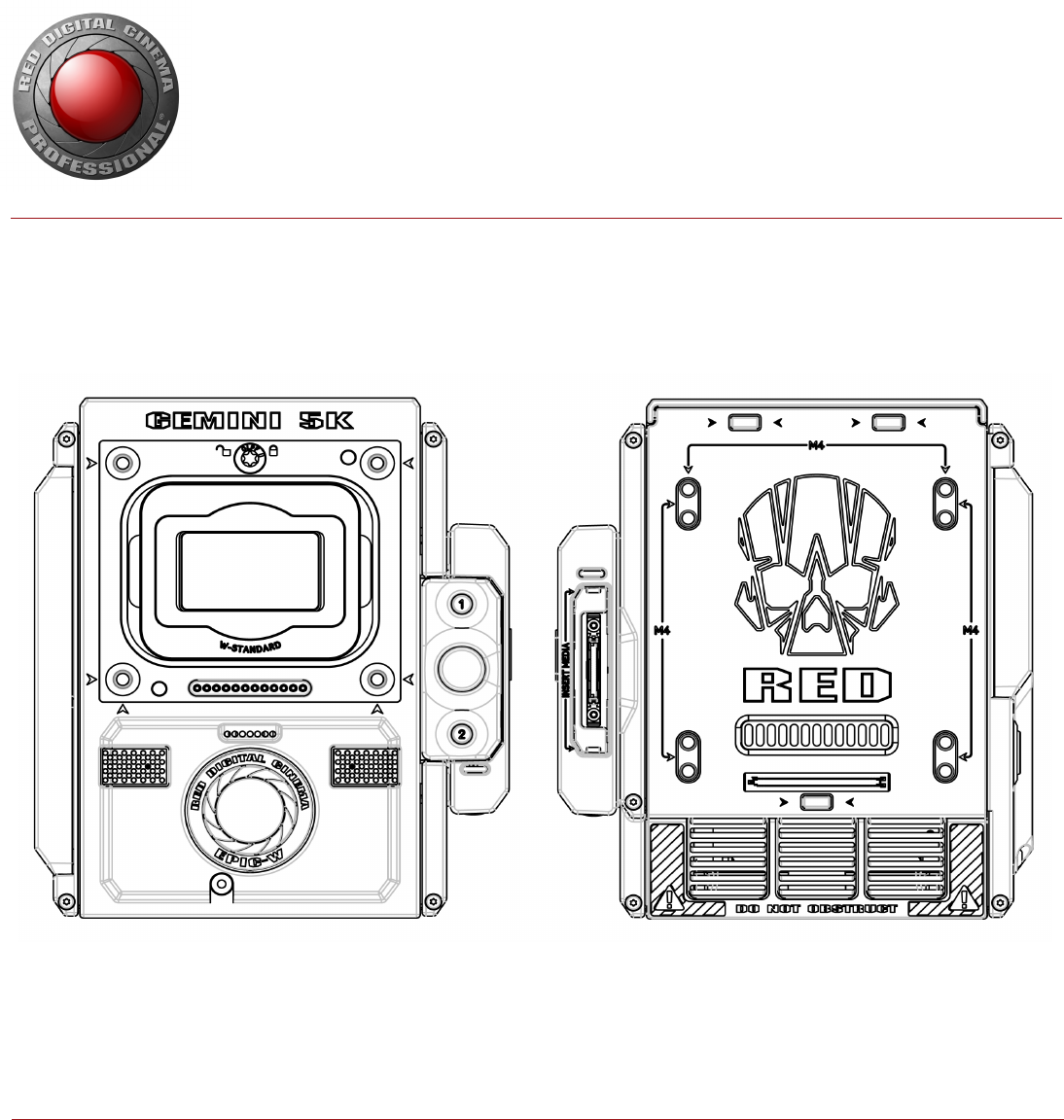
BRAIN
Figure: EPIC-W 5K S35
The DSMC BRAIN® is the image processing center of the camera system and supports power, media, and other
modules.
The only ports on the BRAIN are the DSMC2® Top Handle port and EVF/LCD ports. A port expander or power
module is required to power the camera. All other input/output (I/O) ports are available only via expanders and other
modules. This modular approach allows you to customize your camera and make use of the ports that are most
applicable to your needs.
The RED® Tactical Hand Controller (T.H.C.) cannot pair directly to the camera. To use the T.H.C. with the camera, the
T.H.C. needs to be connected to the W.M.D. (either wired or wirelessly). For more information about the T.H.C., see
the RED 3-Axis System Operation Guide at www.red.com/downloads.

BRAIN CONTROL: PWR/REC KEY
Fully press and hold the PWR/REC key for two (2) seconds to turn on/off.
When the camera is on, fully press and then release the PWR/REC key to toggle record start/stop.
BRAIN LEDS
This section describes the LED functions for the camera.
NOTE: When the camera is powered only by battery and not AC power, the Power Status LED (PWR) on the expander
or module does not turn on. To check the battery charge level, press the button on the battery.
LED COLOR/FLASHING DESCRIPTION
Power Status LED (PWR) Off Camera off
Green Camera on
Amber flashing Camera on; 5 to 10 min of battery time available
Amber Camera booting
Red flashing Camera on; < 5 min of battery time available
Red Camera shutting down
Record Status LED (REC) Off No media present
Green Ready to record
Amber Finalizing
Red flashing (slow) Media mounted; > 5% and ≤ 10% of media available
Red flashing (fast) Media mounted; ≤ 5% of media available
Red Recording
Power Status LED (PWR)
and Record Status LED (REC)
Both green flashing Firmware update in progress
Both red flashing Firmware update error
C OPYR I GHT © 2 01 9 R ED. C OM , LLC 955- 0159_V 7. 1, R EV -G | 14
EPIC-W GEMINI OPERATION GUIDE
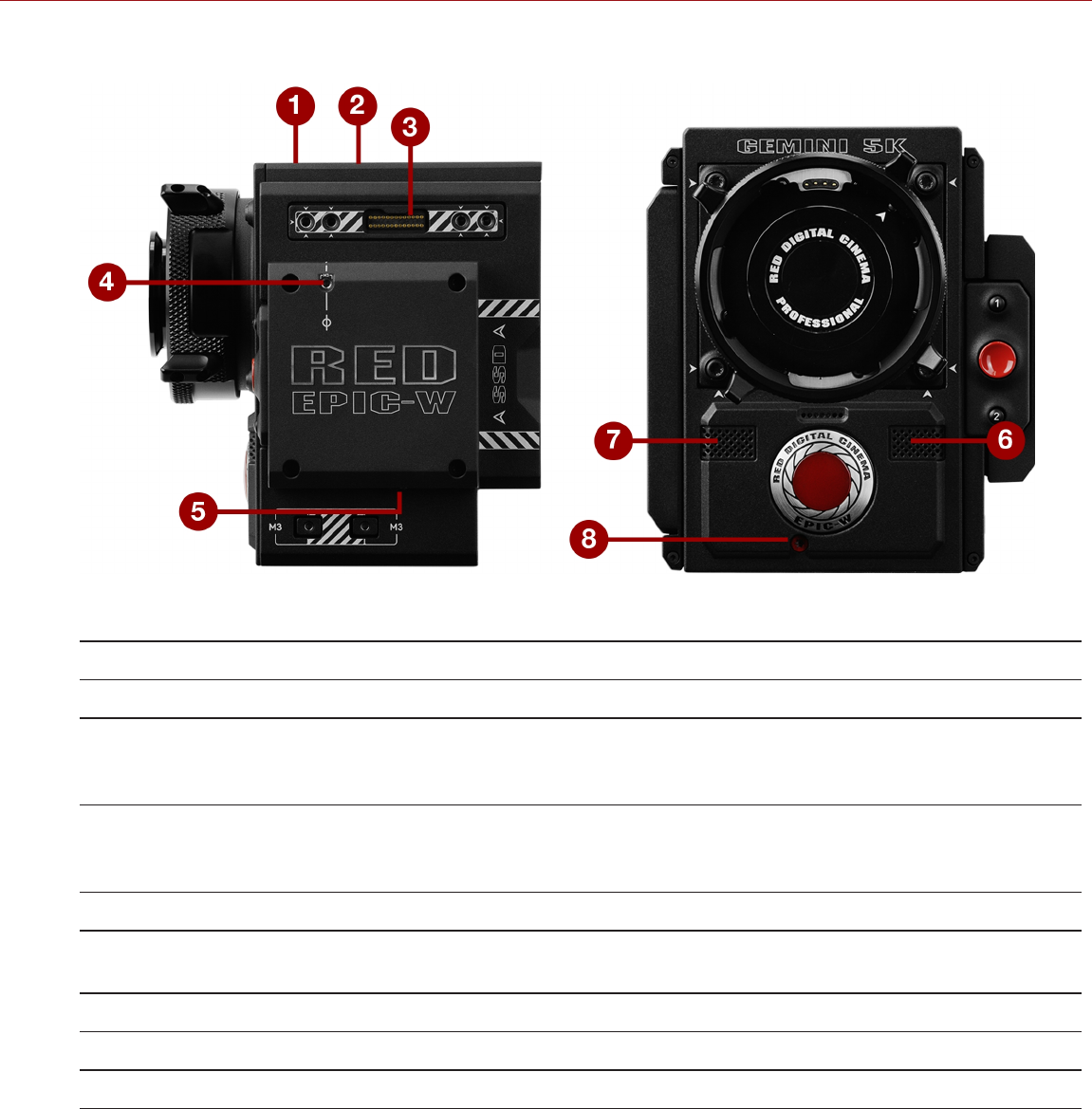
BRAIN CONNECTORS, FOCUS HOOK, AND BACK FOCUS
Figure: EPIC-W 5K S35 Ports and Features
# PORT/ITEM DESCRIPTION
1 Primary EVF/LCD Port1Mount a DSMC2 RED Touch LCD
2 Top Handle Port Mount the DSMC2 Top Handle or DSMC2 Outrigger Handle. This is the only
mounting option for the DSMC2 Top Handle or DSMC2 Outrigger Handle (it
cannot be attached backward)
3 Secondary EVF/LCD Port1Mount a DSMC2 RED Touch LCD. The secondary LCD/EVF port and an
HDMI/MON-1 port cannot be used at the same time. Go to "Monitor
Preferences" on page90
4 Focus Hook Mounting Point2, 3 Mount the focus hook
5 Focus Hook Screw Storage
Location2Store the focus hook screw
6 Mic 1 Left audio channels: Ch1 and Ch3. Go to "Audio System" on page166
7 Mic 2 Right audio channels: Ch2 and Ch4. Go to "Audio System" on page166
8 Back Focus Adjustment Screw Adjust back focus
1. The DSMC2 LCD/EVF Adaptor A allows you to mount other RED® displays.
2. Install only the focus hook screw to this mounting point. Damage to the media bay or other components of the camera system caused by
installing other devices is not covered under warranty.
3. Cameras manufactured before December 2017 include a set screw installed in this location. This screw can be stored in either the Focus Hook
Mounting Point, or the Focus Hook Storage location.
C OPYR I GHT © 2 01 9 R ED. C OM , LLC 955- 0159_V 7. 1, R EV -G | 15
EPIC-W GEMINI OPERATION GUIDE
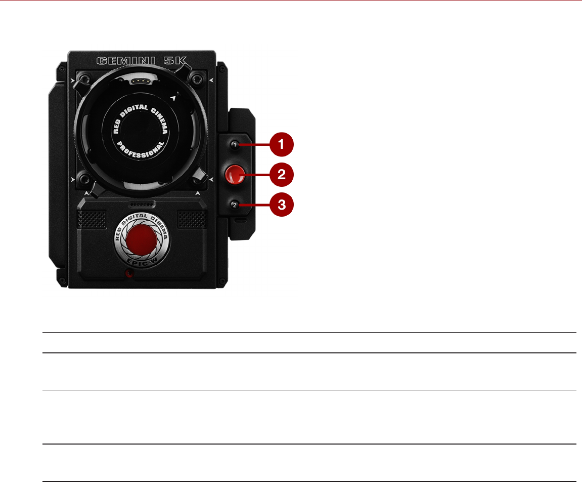
MEDIA BAY CONTROLS
Figure: EPIC-W 5K S35 Media Bay Controls
# CONTROL DESCRIPTION
1 User Key 1 Programmable key
User Key 1 + 2 Press: Eject Media
2 REC Button Programmable key
Full Press: Record Toggle
Half Press: AF Start
3 User Key 2 Programmable key
User Key 1 + 2 Press: Eject Media
For more information, see the DSMC Media Operation Guide, available at www.red.com/downloads.
C OPYR I GHT © 2 01 9 R ED. C OM , LLC 955- 0159_V 7. 1, R EV -G | 16
EPIC-W GEMINI OPERATION GUIDE
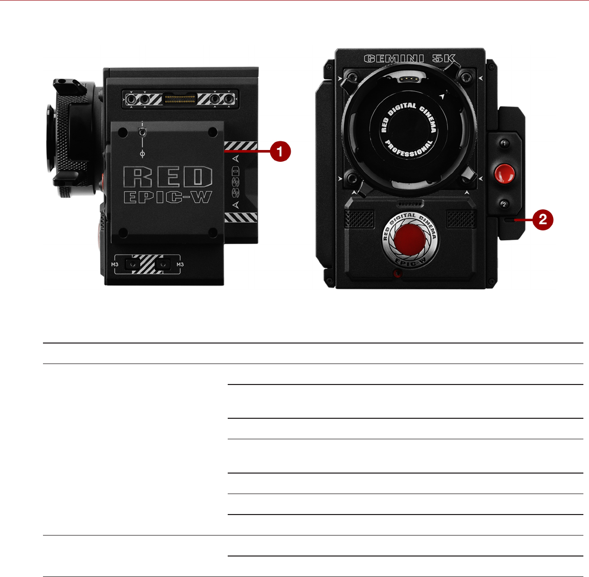
MEDIA BAY LEDS
Figure: EPIC-W 5K S35 Media Bay LEDs
This section describes the LED functions for the media bay.
# LED COLOR/FLASHING DESCRIPTION
1 Media Status LED (Back of media
bay)
Off No media mounted
Green Preview; media mounted; > 10% of media space
available
Amber Record finalizing or playback mode
Amber flashing
(slow)
Formatting media
Red flashing (slow) Media mounted; > 5% and ≤ 10% of media available
Red flashing (fast) Media mounted; ≤ 5% of media available
Red Recording; media mounted; > 10% of media available
2 Record Status LED1Off Not recording, or media not mounted
Red Recording
1. For more information on how to enable/disable this LED, go to "Indicator" on page135. If media is not mounted, this LED is off.
C OPYR I GHT © 2 01 9 R ED. C OM , LLC 955- 0159_V 7. 1, R EV -G | 17
EPIC-W GEMINI OPERATION GUIDE
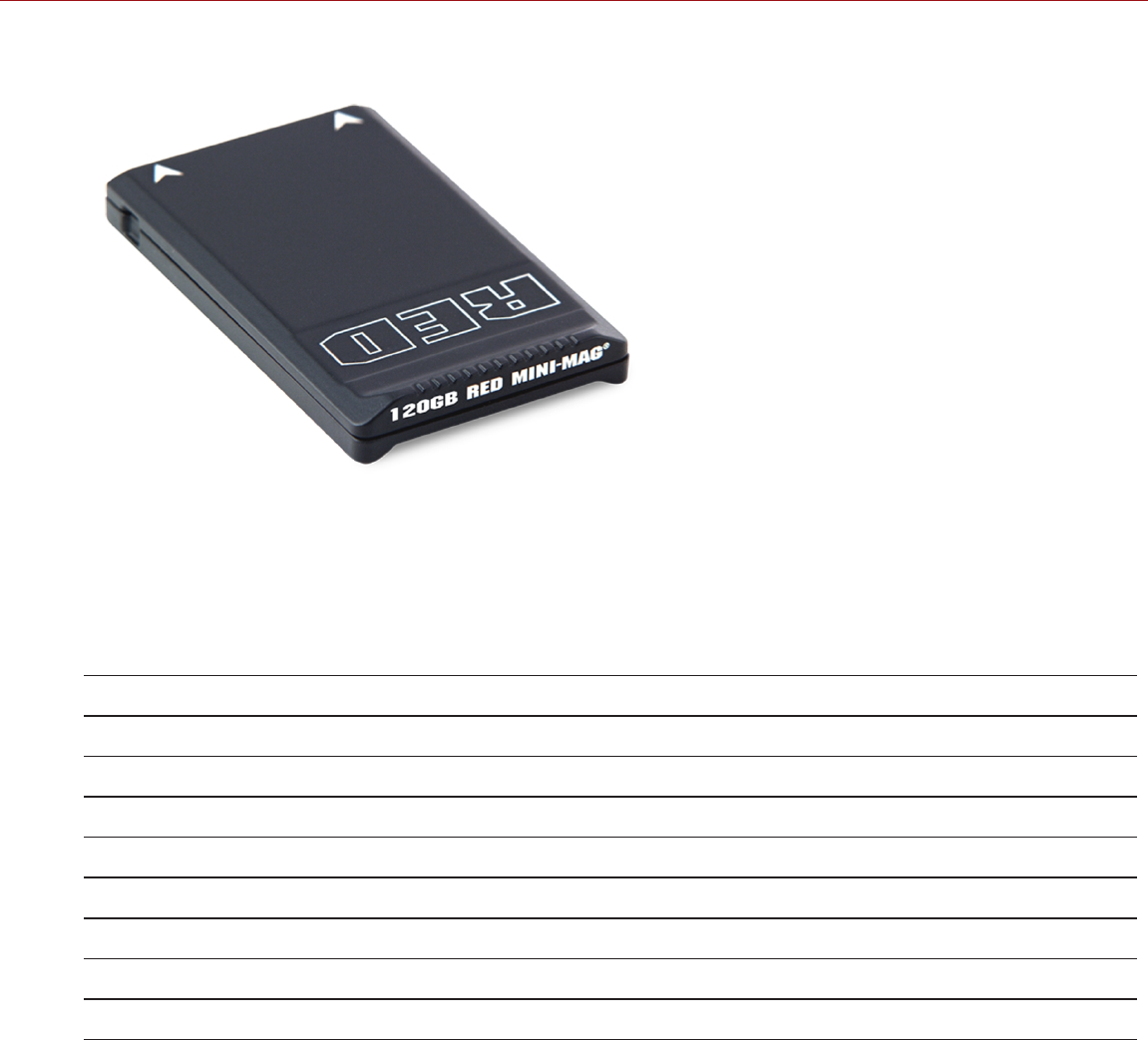
RED MINI-MAG SYSTEM
Figure: RED MINI-MAG (120GB)
NOTE: For more information, see the DSMC Media Operation Guide, available at www.red.com/downloads.
RED MINI-MAG® SSDs deliver fast and reliable recording options for your camera. A RED STATION® enables you to
connect media to your computer for offloading and editing.
RED offers the following RED MINI-MAG SSDs:
ITEM PART NUMBER
RED MINI-MAG (120GB) 750-0075
RED MINI-MAG (240GB) 750-0082
RED MINI-MAG (480GB) 750-0090
RED MINI-MAG (512GB) V41750-0078
RED MINI-MAG (512GB) V51750-0078
RED MINI-MAG (512GB) V61750-0078
RED MINI-MAG (960GB) 750-0087
RED MINI-MAG (1TB)2750-0081
1. To see the Model number, go to Menu > Media > Device.
2. The RED MINI-MAG 1TB can take up to 20 seconds to mount to a computer or a camera.
C OPYR I GHT © 2 01 9 R ED. C OM , LLC 955- 0159_V 7. 1, R EV -G | 18
EPIC-W GEMINI OPERATION GUIDE
EXPANDERS
NOTE: Only one (1) expander module can be used at a time.
RED offers the following DSMC2 expanders:
ITEM PART NUMBER
DSMC2 Base Expander 720-0033
DSMC2 REDVOLT Expander 720-0040
DSMC2 Jetpack Expander 720-0039
DSMC2 Jetpack-SDI Expander 720-0048
DSMC2 V-Lock I/O Expander 720-0045
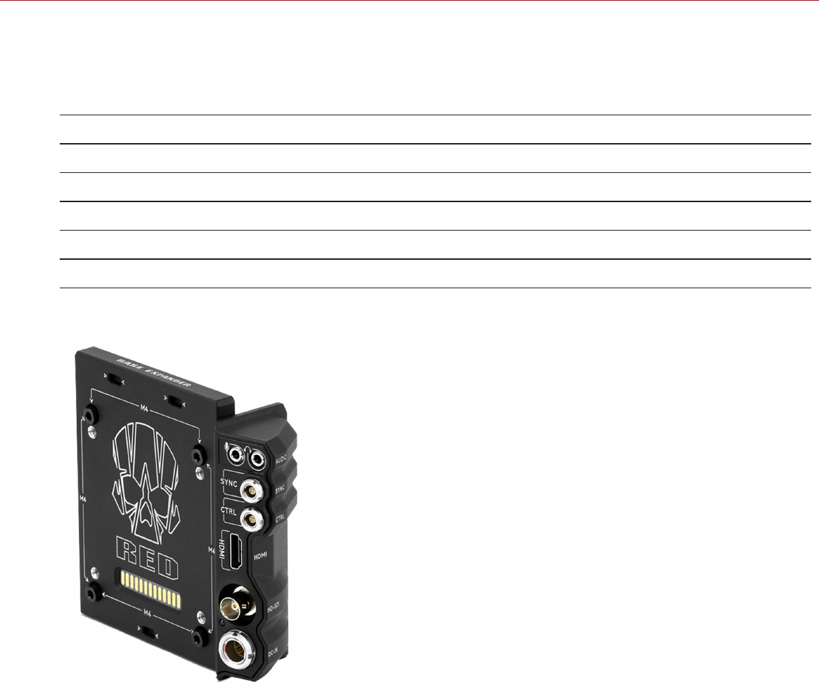
DSMC2 BASE EXPANDER
Figure: DSMC2 Base Expander
The DSMC2 Base Expander is an ideal connector module for general input/output (I/O) needs. Manufactured from
lightweight and durable magnesium, this low-profile module mounts directly to the BRAIN and offers interface
connections for power (DC IN), HDMI, 3G-SDI (HD-SDI), CTRL and SYNC ports (for Timecode and Genlock), as well
as a 3.5mm microphone input and a 3.5mm line-level headphone out.
The DSMC2 Base Expander also offers rear-mounting support for DSMC2-compatible battery and power modules,
such as the DSMC2 REDVOLT® XL Module. The low profile DSMC2 Base Expander offers a variety of connectors and
is ideal for run-and-gun and independent shooters.
NOTE: Only one (1) expander module can be used at a time.
C OPYR I GHT © 2 01 9 R ED. C OM , LLC 955- 0159_V 7. 1, R EV -G | 19
EPIC-W GEMINI OPERATION GUIDE
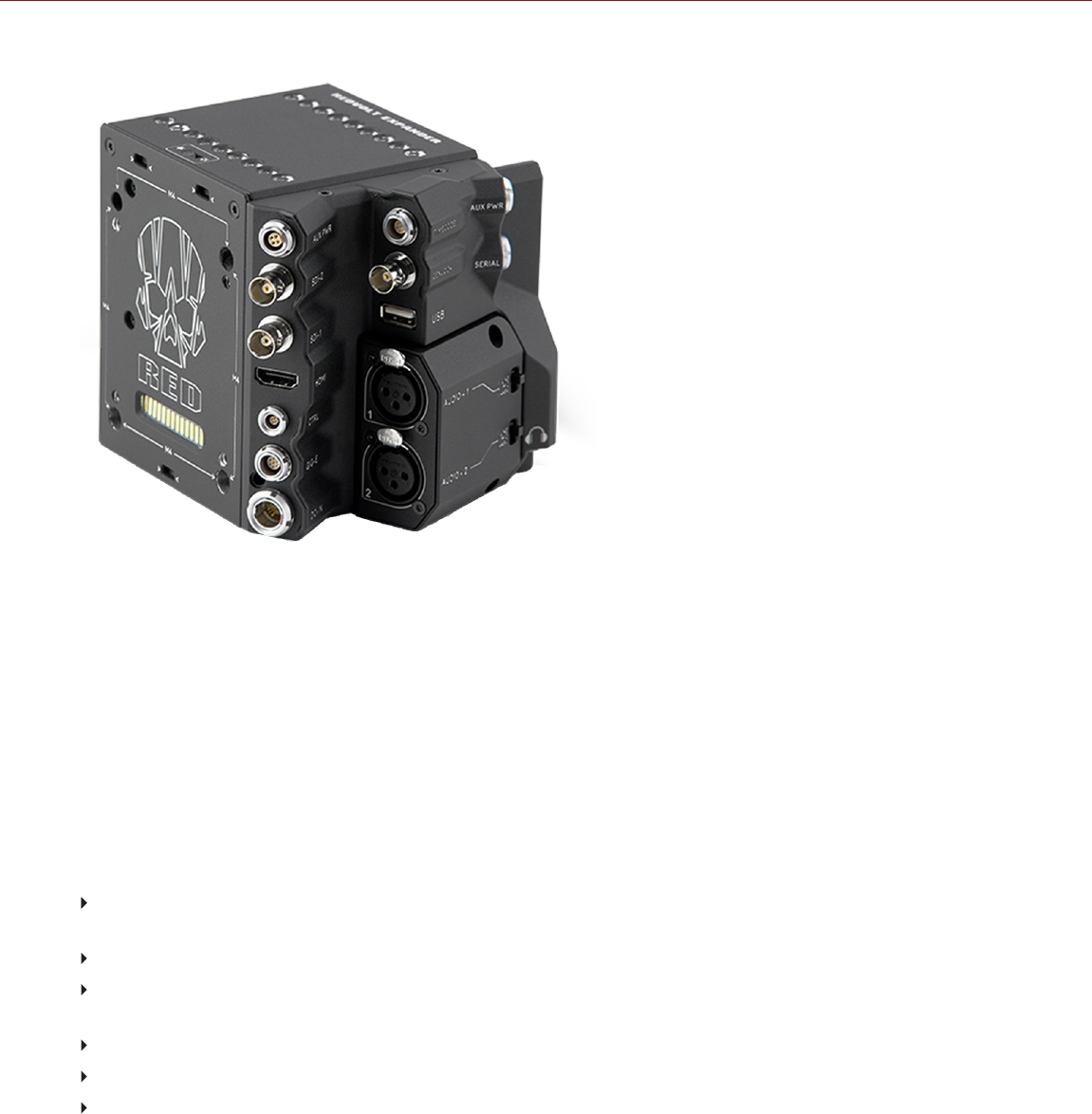
DSMC2 REDVOLT EXPANDER
Figure: DSMC2 REDVOLT Expander
Designed for advanced configurations, the DSMC2 REDVOLT Expander mounts directly to the camera and offers an
expansive array of I/O connectors and functionality available for the camera system. The DSMC2 REDVOLT Expander
features ports for power in (DC IN), Genlock (BNC), 5-Pin 0B Timecode port, GIG-E, and more. HDMI and two 3G-SDI
(HD-SDI) outputs offer versatility for your video output needs, while an integrated USB power output is available to
support wireless HDMI transmitters.
The DSMC2 REDVOLT Expander offers a removable audio module with two (2) standard XLR connections for most
professional audio needs. Each XLR input features a 3-position selector switch to designate the incoming audio signal
type: Balanced Line Level, Balanced Mic Level, and Balanced Mic with +48V phantom power. Additionally, a 3.5mm
line-level headphone jack lets you sample audio during takes and in playback mode.
The DSMC2 REDVOLT Expander also provides multiple auxiliary power outputs, enabling the use of peripheral camera
accessories and more:
A rear-facing 4-Pin 0B AUX PWR port supports Start/Stop Trigger IN, Tally OUT, and provides power out up to 1.5
Amps.
A front-facing2-Pin 0B AUX PWR port provides 3.0A maximum.
A front-facing 7-Pin 0B SERIAL port provides 1.5A maximum. The SERIAL port is ideal for connecting to motor
drivers.
A rear-facing Timecode port offers 5V at 200 mA for powering external timecode devices.
A rear-facing USB port offers 5V at 1.5A for powering HDMI transmitters or small mobile devices.
The two (2) 3-Pin XLR audio ports in the audio module each offer +48V phantom power.
For hot-swap support when it matters most, the DSMC2 REDVOLT Expander also supports a single REDVOLT
battery. Additional DSMC2-compatible battery and power modules can be mounted for your changing power needs.
C OPYR I GHT © 2 01 9 R ED. C OM , LLC 955- 0159_V 7. 1, R EV -G | 20
EPIC-W GEMINI OPERATION GUIDE
The DSMC2 REDVOLT Expander also features a selector switch that enables the camera to automatically boot when
power is provided via the DC IN connector on the expander. This feature allows you to use a connected DC input
supply to turn the camera on and off when the camera is mounted in remote or difficult to maneuver locations. This
expander is the ideal solution for a variety of production environments, maximizing camera interface and functionality
for the most demanding shoots.
CAUTION: The mounting points on top of the DSMC2 REDVOLT Expander are designed for lightweight accessories
only. DONOT use accessories attached to the expander to pick up or move the camera.
NOTE: Only one (1) expander module can be used at a time.
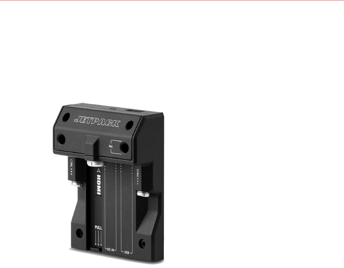
DSMC2 JETPACK EXPANDER
Figure: DSMC2 Jetpack Expander
The DSMC2 Jetpack Expander is specifically designed for aerial, gimbal, handheld, and other lightweight/remote
configurations. This expander features standard connectors for power (DC-IN), CTRL, and SYNC for all of your
Timecode and Genlock needs. In addition, the DSMC2 Jetpack Expander offers custom-tailored support and
connectors for HDMI and USB power out—perfect for housings and low-profile setups.
The DSMC2 Jetpack Expander also features a selector switch that enables the camera to automatically boot when
power is provided via the DC IN connector on the expander. This feature allows you to use a connected DC input
supply to turn the camera on and off when the camera is mounted in remote or difficult to maneuver locations.
NOTE: Only one (1) expander module can be used at a time.
C OPYR I GHT © 2 01 9 R ED. C OM , LLC 955- 0159_V 7. 1, R EV -G | 21
EPIC-W GEMINI OPERATION GUIDE

DSMC2 JETPACK-SDI EXPANDER
Figure: DSMC2 Jetpack-SDI Expander
The DSMC2 Jetpack-SDI Expander is designed for aerial, gimbal, handheld, and other lightweight/remote applications
that require 3G-SDI output. Featuring connections for power (DC IN), SDI (3G-SDI), Gigabit Ethernet (GIG-E), AUX
power, SYNC, and CTRL, the DSMC2 Jetpack-SDI Expander provides a low-profile expander solution. The 3G-SDI
connection provides support for providing a signal to a remote monitoring solution, while the Gigabit Ethernet
connection offers increased bandwidth for streaming high-quality footage.The DSMC2 Jetpack-SDI Expander is ideal
for housings and low-profile configurations that require 3G-SDI outputs or computer tethering.
The DSMC2 Jetpack-SDI Expander also features a selector switch that enables the DSMC2 BRAIN to automatically
boot when power is provided via the DC IN connector on the expander. This feature allows you to use a connected
DC input supply to turn the BRAIN on and off when the camera is mounted in remote or difficult to maneuver locations.
NOTE: Only one (1) expander module can be used at a time.
C OPYR I GHT © 2 01 9 R ED. C OM , LLC 955- 0159_V 7. 1, R EV -G | 22
EPIC-W GEMINI OPERATION GUIDE

DSMC2 V-LOCK I/O EXPANDER
Figure: DSMC2 V-Lock I/O Expander
The DSMC2 V-Lock I/O Expander offers a variety of Input/Output connections, as well as an industry standard V-Lock
mount to power your DSMC2 camera using RED BRICK and REDVOLT-V batteries.
The DSMC2 V-Lock I/O Expander also features a selector switch that enables the BRAIN to automatically boot when
power is provided via the DC IN connector on the expander. This feature allows you to use a connected DC input
supply to turn the BRAIN on and off when the camera is mounted in remote or difficult to maneuver locations.
This expander is an ideal solution for a wide variety of production environments—from low-profile run-and-gun
situations to studio shoots that require mobility.
NOTE: The DSMC2 Top Handle may not be fully compatible with the DSMC2 V-Lock I/O Expander, as the top handle
may interfere with the battery when one is attached to the expander module.
NOTE: Only one (1) expander module can be used at a time.
C OPYR I GHT © 2 01 9 R ED. C OM , LLC 955- 0159_V 7. 1, R EV -G | 23
EPIC-W GEMINI OPERATION GUIDE

THIRD-PARTY BATTERY COMPATIBILITY
To be compatible with the DSMC2 V-Lock I/O Expander, third-party batteries must meet these requirements:
Maximum width: approximately 100.6 mm
Minimum radius of the side edge of the V-mount (rear mounting surface): approximately 9.70 mm
The following third-party batteries have been fit-tested by RED and are mechanically compatible with the DSMC2 V-
Lock I/O Expander (additional batteries may be compatible, but have not been tested):
Blueshape® (All BV series)
IDX® (E-HL10DS and E-HL9)
Sony® (BP-FL75)
Switronix (Hypercore series and XP-L90S)
WARNING: While third-party batteries may be mechanically compatible with the camera system, the manufacturer is
responsible for the performance and stability of third-party options, not RED. Damage to the camera system or third-
party devices caused by using third-party power options is not covered under warranty. The camera may be unable to
determine and display the voltage or remaining battery capacity of third-party power options.
C OPYR I GHT © 2 01 9 R ED. C OM , LLC 955- 0159_V 7. 1, R EV -G | 24
EPIC-W GEMINI OPERATION GUIDE
DSMC2 POWER MODULES
ITEM PART NUMBER
DSMC2 REDVOLT XL Module 740-0034
DSMC2 V-Lock Battery Module 720-0052
DSMC2 Gold Mount Battery Module1720-0053
DSMC2 Production Module (V-Lock) 720-0054
1. The DSMC2 Gold Mount Battery Module supports Gold Mount batteries only.
NOTE: If a power module is attached to the DSMC2 REDVOLT Expander, the power out connectors on the module are
enabled only if power is connected to the module (via DC IN or a battery).
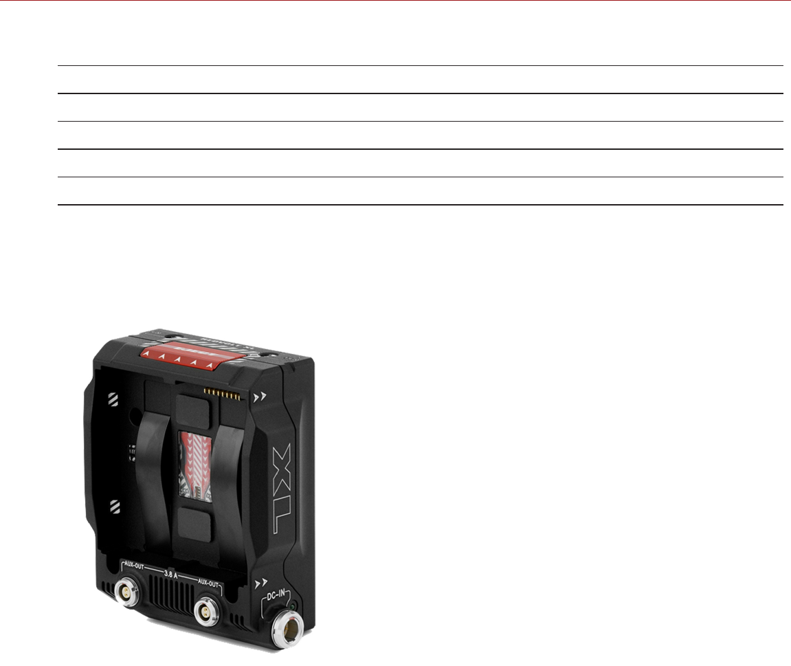
DSMC2 REDVOLT XL MODULE
Figure: DSMC2 REDVOLT XL Module
The DSMC2 REDVOLT XL Module mounts seamlessly to the back of the camera—and select other I/O expanders—to
provide support for long-lasting and rechargeable REDVOLT XL batteries. The DSMC2 REDVOLT XL Module features
a smaller, more ergonomic design with one (1) dual-action release button for removing an attached battery.
The DSMC2 REDVOLT XL Module offers a DC IN power port that can be used to power the camera system when the
module is attached to the camera. An included protective baseplate enables the DSMC2 REDVOLT XL Module to
serve as a portable and stand-alone REDVOLT XL battery charger. Plug in the DSMC AC Power Adaptor to the 6-Pin
1B DC IN connector on the module and connect a REDVOLT XL battery. While the module is mounted to the camera, it
will only charge an attached REDVOLT XL battery if the camera is powered off.
Two (2) rear facing auxiliary ports provide power for external camera accessories, while remaining out of the way while
shooting.
C OPYR I GHT © 2 01 9 R ED. C OM , LLC 955- 0159_V 7. 1, R EV -G | 25
EPIC-W GEMINI OPERATION GUIDE

DSMC2 V-LOCK BATTERY MODULE
Figure: DSMC2 V-Lock Battery Module
The DSMC2 V-Lock Battery Module is a low profile cable-free module that enables you to power your DSMC2 BRAIN
and camera accessories using RED BRICK, REDVOLT-V, or other standard V-Lock batteries. The V-Lock mount and
protected release button ensure ongoing power even during mobile shoots.
This DSMC2 battery module offers a P-Tap connector on top and an auxiliary port on the side for powering
peripherals and accessories. Together the P-Tap and auxiliary connectors support a maximum combined current of
3.8 Amps.
This module also offers a DC IN power port that can be used to power the camera system when the module is
attached to the BRAIN. When DC IN power is supplied to the module, and the camera is turned off, this module can
also trickle charge the attached V-Lock battery.
Manufactured from robust aluminum alloy, this DSMC2 battery module offers a blend of utility and power support in a
lightweight and space-saving form factor. The DSMC2 V-Lock Battery Module is an ideal power solution for use with
most DSMC2 expanders. Alternatively, connect the DSMC2 V-Lock Battery Module directly to your DSMC2 BRAIN for
a low-profile, battery-only power configuration.
NOTE: This design of the DSMC2 V-Lock Battery Module (720-0052) replaces the earlier version of the module (720-
0049), which did not have the AUXOUT and DCINports. All other functionality is the same.
C OPYR I GHT © 2 01 9 R ED. C OM , LLC 955- 0159_V 7. 1, R EV -G | 26
EPIC-W GEMINI OPERATION GUIDE

DSMC2 GOLD MOUNT BATTERY MODULE
Figure: DSMC2 Gold Mount Battery Module
The DSMC2 Gold Mount Battery Module is a low profile cable-free module that enables you to power your DSMC2
BRAIN and camera accessories using standard Gold Mount batteries. The Gold Mount and protected release button
ensure ongoing power even during mobile shoots.
This DSMC2 battery module offers a P-Tap connector on top and an auxiliary port on the side for powering
peripherals and accessories. Together the P-Tap and auxiliary connectors support a maximum combined current of
3.8 Amps.
This module also offers a DC IN power port that can be used to power the camera system when the module is
attached to the BRAIN. When DC IN power is supplied to the module, and the camera is turned off, this module can
also trickle charge a wide variety of attached Gold Mount batteries.
Manufactured from robust aluminum alloy, this DSMC2 battery module offers a blend of utility and power support in a
lightweight and space-saving form factor. The DSMC2 Gold Mount Battery Module is an ideal power solution for use
with most DSMC2 expanders. Alternatively, connect the DSMC2 Gold Mount Battery Module directly to your DSMC2
BRAIN for a low-profile, battery-only power configuration.
C OPYR I GHT © 2 01 9 R ED. C OM , LLC 955- 0159_V 7. 1, R EV -G | 27
EPIC-W GEMINI OPERATION GUIDE
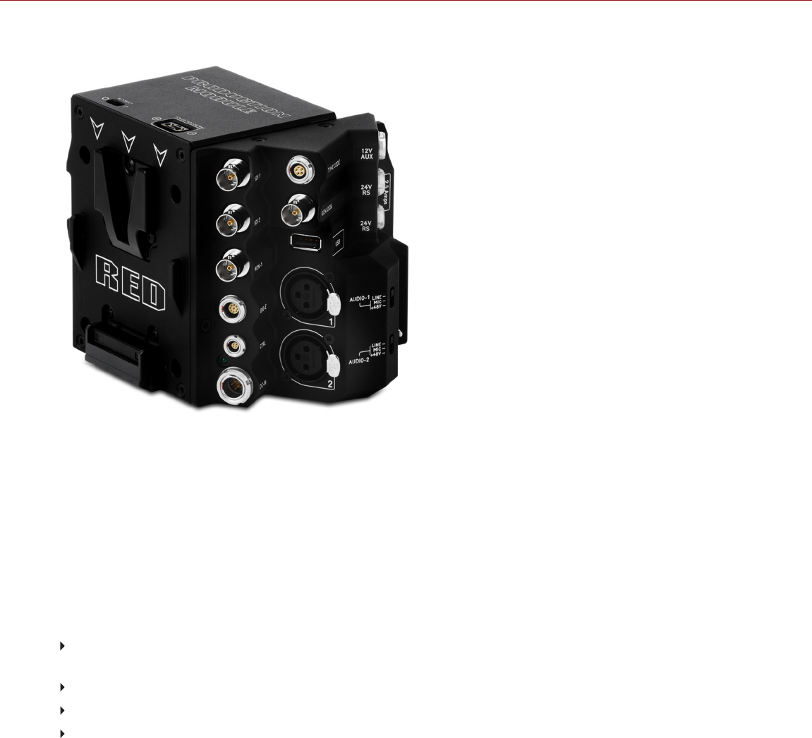
DSMC2 PRODUCTION MODULE (V-LOCK)
Figure: DSMC2 Production Module (V-Lock)
Designed for professional shooting configurations, the DSMC2 Production Module (V-Lock) mounts directly to the
BRAIN and offers a comprehensive array of video, power, communication, and pro audio connections. Constructed
from lightweight and durable aluminum alloy, this module incorporates an industry standard V-Lock mount to power
your DSMC2 camera when using RED BRICK, REDVOLT-V, or other v-lock batteries.
The DSMC2 Production Module (V-Lock) includes three (3) BNC video connectors for maximum monitoring flexibility
on-set. Two (2) connectors output a cloned 3G-SDI signal, and one (1) connector serves as an independent monitoring
output.
To support production demands for on-board monitors, wireless video transmitters, wireless lens control, and focus
assist systems, the module includes multiple auxiliary power outputs:
Two (2) front-facing 3-Pin Fischer R/S ports support Remote Start/Stop functionality, and provide 24V power out
up to a combined 2.5 Amps.
A front-facing2-Pin 0B AUX PWR port provides power out up to 3.0 Amps.
A 2-Pin P-Tap connector on the top provides power out up to 3.0 Amps.
A rear-facing USB 2.0 port with support for fast charging offers 5V at 1.5 Amps for powering small mobile devices.
Two (2) standard XLR connections are included for most professional audio needs. Each XLR input features a 3-
position selector switch to designate the incoming audio signal type: Balanced Line Level, Balanced Mic Level, and
Balanced Mic with +48V phantom power. Additionally, a 3.5mm line-level headphone jack allows users to monitor
audio during takes and in playback mode.
The module features ports for power in (DC IN), Genlock (BNC), 5-Pin 0B Timecode port, GIG-E, and CTRL.
The module also features a selector switch that enables the BRAIN to automatically boot when power is provided via
the DC IN connector on the module. This feature allows operators to use a connected DC input supply to turn the
BRAIN on and off when the camera is mounted in remote or difficult to maneuver locations.
NOTE: Only one (1) module can be used at a time.
C OPYR I GHT © 2 01 9 R ED. C OM , LLC 955- 0159_V 7. 1, R EV -G | 28
EPIC-W GEMINI OPERATION GUIDE

RED BATTERIES AND CHARGERS
Figure: REDVOLT XL (left) and REDVOLT (right)
The REDVOLT, REDVOLT-V, REDVOLT XL, and RED BRICK are lightweight, rechargeable lithium-ion battery cells that
provide sustained power to the camera. These batteries provide long-term mobile power and attach to the camera via
a power module or other RED accessory. RED chargers replenish lost capacity for REDVOLT, REDVOLT-V, REDVOLT
XL, and RED BRICK batteries.
RED offers the following batteries and chargers:
ITEM PART NUMBER
REDVOLT 740-0020
REDVOLT-V 740-0043
REDVOLT XL 740-0021
RED BRICK 740-0002
REDVOLT Travel Charger 790-0134
REDVOLT Charger (Quad) 740-0015
RED CHARGER 740-0006
For more information, see the DSMC Power Operation Guide, available at www.red.com/downloads.
C OPYR I GHT © 2 01 9 R ED. C OM , LLC 955- 0159_V 7. 1, R EV -G | 29
EPIC-W GEMINI OPERATION GUIDE

DISPLAYS AND ELECTRONIC VIEWFINDERS
RED offers the following displays and electronic viewfinders (EVFs):
NOTE: RED offers multiple mounting solutions for each camera type.
ITEM RESOLUTION TILT1SWIVEL1PART NUMBER
DSMC2 RED Touch 7.0" LCD (Woven CF) 1920 x 1136 Total: 180°
Forward: 90°
Backward: 90°
Total: 360°
CW: 180°
CCW: 180°
730-0018
DSMC2 RED Touch 7.0" LCD (Aluminum) 1920 x 1136 Total: 180°
Forward: 90°
Backward: 90°
Total: 360°
CW: 180°
CCW: 180°
730-0024
DSMC2 RED Touch 4.7" LCD 1280 x 720 Total: 240°
Forward: 90°
Backward: 150°
No swivel 730-0019
RED Touch 5.0" LCD2800 x 400 Total: 270°
Forward: 180°
Backward: 90°
Total: 360°
CW: 180°
CCW: 180°
730-0008
RED Touch 7.0" LCD2, 3 1920 x 1136 Total: 180°
Forward: 90°
Backward: 90°
Total: 360°
CW: 180°
CCW: 180°
730-0007
RED Touch 9.0" LCD21280 x 768 Total: 270°
Forward: 180°
Backward: 90°
Total: 360°
CW: 180°
CCW: 180°
730-0011
RED Pro LCD 7"21024 x 600 No tilt No swivel 730-0009
RED Pro Touch 7.0" LCD21920 × 1136 No tilt No swivel 730-0025
DSMC2 Touch 7.0" Ultra-Brite LCD2, 4 1920 x 1200 No tilt No swivel 730-0026
DSMC2 RED EVF (OLED)21920 x 1080 N/A N/A 730-0021
BOMB EVF® (LCOS)21280 x 784 N/A N/A 730-0004
BOMB EVF (OLED)21280 x 1024 N/A N/A 730-0010
1. Approximate measurements.
2. Using this display with a DSMC2 camera requires a DSMC2 LCD/EVF Adaptor A, DSMC2 Tactical Top Plate, or DSMC2 Production Top Plate.
3. The RED Touch 7.0" LCD requires that your camera is on firmware v5.2.38 or later.
4. The DSMC2 Touch 7.0" Ultra-Brite LCD requires that your camera is on firmware v7.2 or later.
C OPYR I GHT © 2 01 9 R ED. C OM , LLC 955- 0159_V 7. 1, R EV -G | 30
EPIC-W GEMINI OPERATION GUIDE

RED LCDS
Figure: DSMC2 RED Touch 7.0" LCD
RED displays provide important camera parameters on the graphical user interface (GUI) and offer a variety of monitor
viewing options. RED touchscreen displays enable you to use gestures to navigate menus and adjust camera
parameters. RED displays feature 8-bit RGB, 4:4:4 progressive scan, providing up to 16.7 million colors and up to
70% NTSC color gamut (83% coverage for the DSMC2 Touch 7.0" Ultra-Brite LCD).
LCD PRECAUTIONS
WARNING: DO NOT use a RED display as a handle to lift or carry the camera. Damage to a RED display or other
components of the camera system caused by using the display as a handle are not covered under warranty.
WARNING: DO NOT use the threaded holes in the RED Touch LCD base to mount the display to the camera. Damage
to a RED display or other components of the camera system caused by using these threaded holes is not covered
under warranty.
WARNING: DO NOT try to turn an LCD past its tilt or swivel range. Damage to a RED display or other camera
components caused by excessive force is not covered under warranty. For more information on the tilt and swivel
range for each display, go to "Displays and Electronic Viewfinders" on the previous page.
C OPYR I GHT © 2 01 9 R ED. C OM , LLC 955- 0159_V 7. 1, R EV -G | 31
EPIC-W GEMINI OPERATION GUIDE
BOMB EVFS
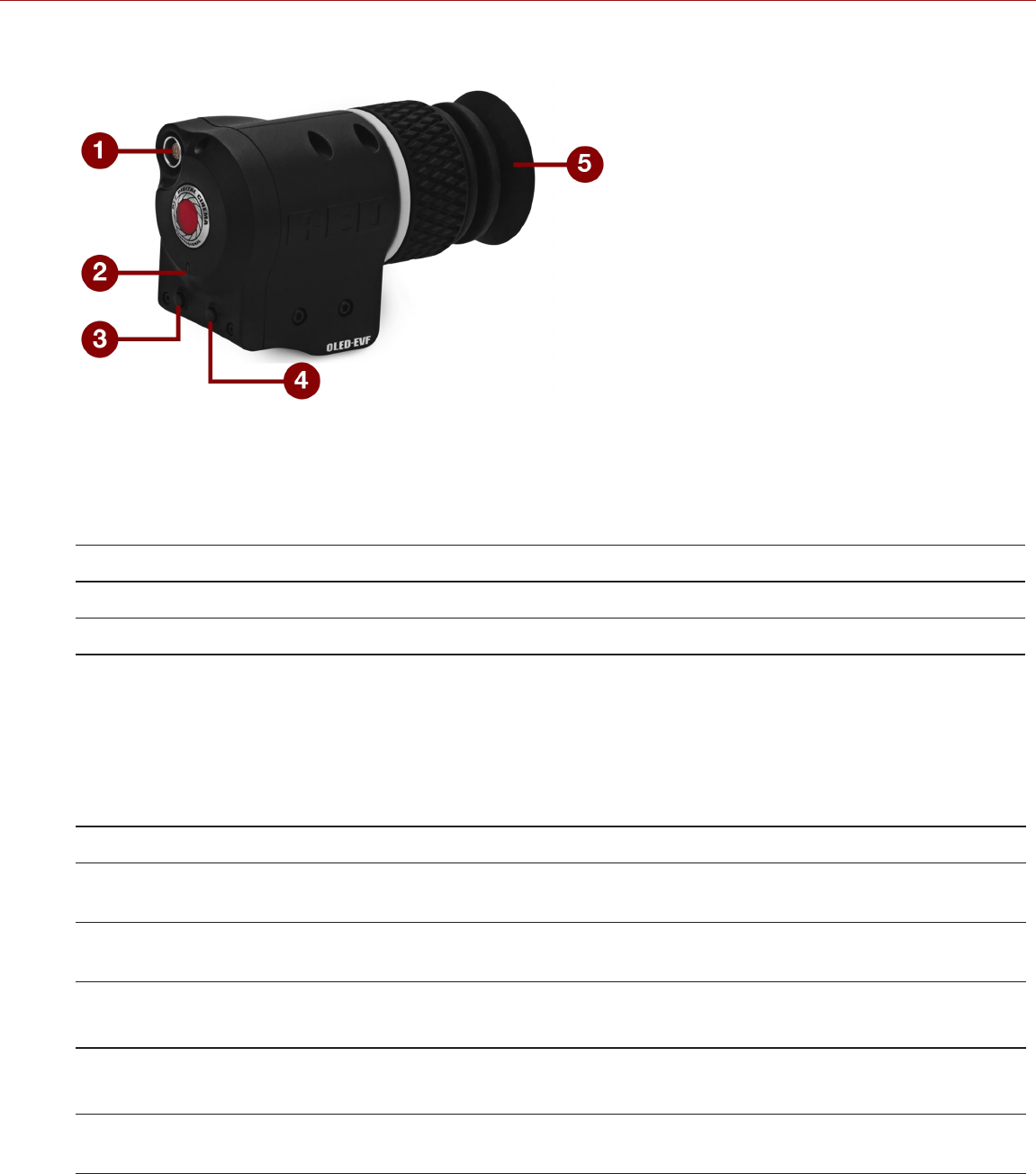
Figure: BOMB EVF (OLED)
The BOMB EVF (LCOS) and BOMB EVF (OLED) deliver specialized viewing solutions for the camera. The BOMB EVF
(LCOS) is a high-definition, lightweight, and low-profile viewfinder. The BOMB EVF (OLED) uses OLED technology,
providing deeper blacks and more color accurate images.
ITEM CONTRAST RATIO DIOPTER RANGE
BOMB EVF (LCOS)11000:1 typical 2.0 to –5.0.1
BOMB EVF (OLED)1>10,000:1 typical 2.0 to –5.0.1
1. Using these displays with a DSMC2 camera requires a DSMC2 LCD/EVF Adaptor A.
WARNING: DO NOT point the BOMB EVF (OLED) eyepiece at direct sunlight. Continued exposure to direct sunlight
may damage the EVF. Point the eyepiece away from sunlight when not in use. Damage to the BOMB EVF (OLED)
caused by continued exposure to direct sunlight is not covered under warranty.
BOMB EVF FEATURES
# FEATURE DESCRIPTION
1 EVF
Connector
Custom digital video and power interconnection between the camera and RED EVF; Pinout not
published
2 EVF Tally
LED
When enabled, the LED illuminates red when recording; For more information, go to "Indicator" on
page135
3 Key 1 Programmable key
Magnify: Toggle
4 Key 2 Programmable key
Exposure Check: Toggle
5 Eyepiece
Heater
The integrated eyepiece heater automatically heats the eyepiece when the EVF detects a low
ambient temperature
C OPYR I GHT © 2 01 9 R ED. C OM , LLC 955- 0159_V 7. 1, R EV -G | 32
EPIC-W GEMINI OPERATION GUIDE

DSMC2 RED EVF
The DSMC2 RED EVF (OLED) is a high definition electronic viewfinder designed as the ideal single-viewer monitoring
solution. Featuring the latest OLED technology, this EVF provides an unmatched personal viewing experience with a
1080p OLED micro-display, and improved color accuracy with 30-bit RGB color represenation. View and monitor your
RED footage as it is intended with truer colors and deeper blacks in a larger field of view.
RED offers multiple mounting solutions for each camera type.
WARNING: DO NOT point the DSMC2 RED EVF (OLED) eyepiece at direct sunlight. Continued exposure to direct
sunlight may damage the EVF. Point the eyepiece away from sunlight when not in use. Damage to the DSMC2 RED
EVF (OLED) caused by continued exposure to direct sunlight is not covered under warranty.
NOTE: DO NOT overtighten the black tension ring on the EVF connector. The EVF is designed to allow rotation even
when the tension ring is fully engaged.
C OPYR I GHT © 2 01 9 R ED. C OM , LLC 955- 0159_V 7. 1, R EV -G | 33
EPIC-W GEMINI OPERATION GUIDE
DSMC2 RED EVF FEATURES
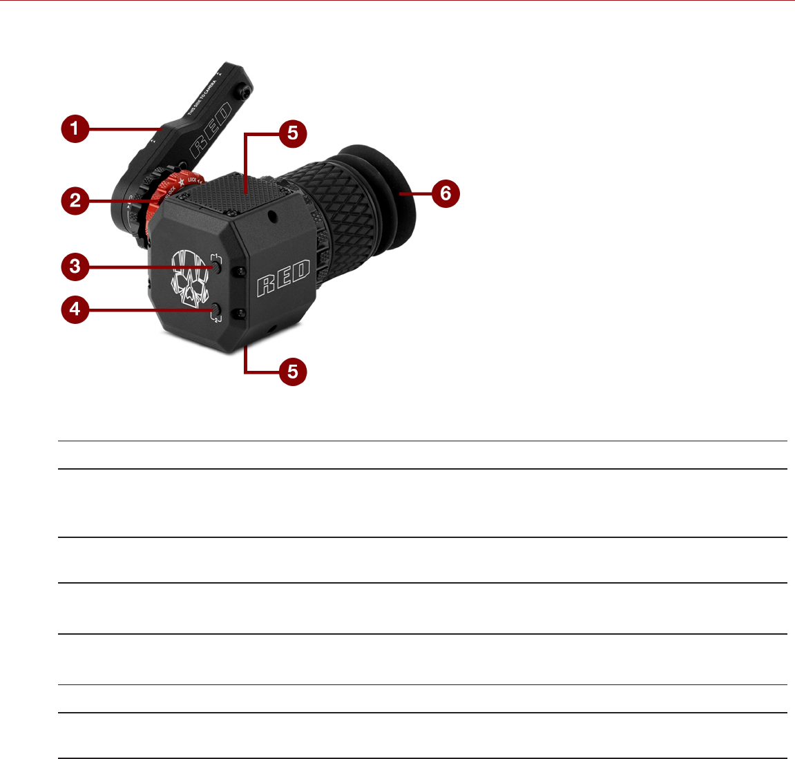
Figure: DSMC2 RED EVF
# FEATURE DESCRIPTION
1 DSMC2 RED EVF
Mount
The DSMC2 RED EVF Mount.
DO NOT overtighten the black tension ring on the EVF connector. The EVF is designed to
allow rotation even when the tension ring is fully engaged.
2 EVF Connector1Custom digital video and power interconnection between the EVF and other RED devices;
Pinout not published; compatible with standard RED LCD/EVF cables.
3 Key 1 Programmable key
Magnify: Toggle
4 Key 2 Programmable key
Exposure Check: Toggle
5 Mounting Point Mounting point for the DSMC2 RED EVF Mounting Plate
6 DSMC2 RED EVF
Modular Optical Block
Fully coated with a > 32° field of view
1. Not visible. Shown with the DSMC2 RED EVF Mount attached.
C OPYR I GHT © 2 01 9 R ED. C OM , LLC 955- 0159_V 7. 1, R EV -G | 34
EPIC-W GEMINI OPERATION GUIDE
LCD/EVF ADAPTORS
This section describes the DSMC2 LCD/EVF Adaptor A and the DSMC2 LCD/EVF Adaptor B. These adaptors enable
you to use EPIC/SCARLET displays with your DSMC2 camera and use DSMC2 displays with your EPIC/SCARLET
camera. For more information on available displays, go to "Displays and Electronic Viewfinders" on page30.
ITEM PART NUMBER
DSMC2 LCD/EVF Adaptor A 720-0037
DSMC2 LCD/EVF Adaptor B 720-0038
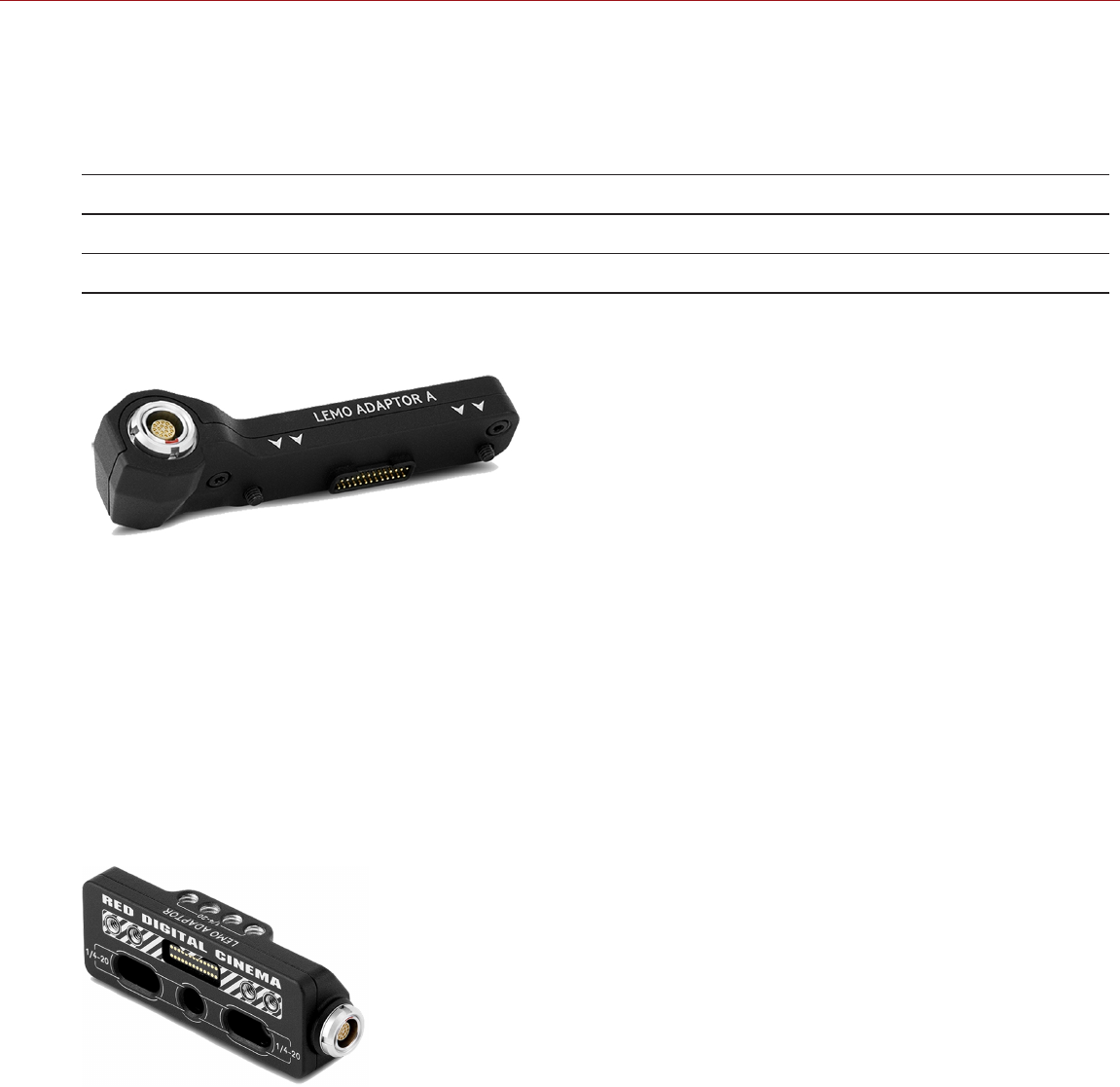
DSMC2 LCD/EVF ADAPTOR A
Figure: DSMC2 LCD/EVF Adaptor A
The DSMC2 LCD/EVF Adaptor A makes your existing RED Touch, RED PRO, and RED PRO Touch displays, as well
as RED EVFs, fully compatible with the DSMC2 camera system. The DSMC2 LCD/EVF Adaptor A converts the pogo
connection on the DSMC2 camera to a 16-Pin 1B LCD/EVF port. The DSMC2 LCD/EVF Adaptor A is designed to
attach to the primary (top), or the secondary (side) EVF/LCD port on the DSMC2 camera.
When used along with the DSMC2 LCD/EVF Adaptor B, this adaptor enables you to mount a DSMC2 RED Touch LCD
away from the camera—to a NOGA arm or other stable mounting point.
The DSMC2 LCD/EVF Adaptor A is compatible with the BOMB EVF, (LCOS) and (OLED) models, or later.
DSMC2 LCD/EVF ADAPTOR B
Figure: DSMC2 LCD/EVF Adaptor B
The DSMC2 LCD/EVF Adaptor B enables you to use a DSMC2 RED Touch LCD with your existing EPIC or SCARLET
camera. The DSMC2 LCD/EVF Adaptor B converts the display signal from a pogo connection to a 16-Pin 1B LCD/EVF
port. The DSMC2 LCD/EVF Adaptor B is designed to mount to your EPIC or SCARLET camera using standard 1/4-20
mounting holes.
When used along with the DSMC2 LCD/EVF Adaptor A, this adaptor enables you to mount a DSMC2 RED Touch LCD
away from the camera—to a NOGA arm or other stable mounting point.
C OPYR I GHT © 2 01 9 R ED. C OM , LLC 955- 0159_V 7. 1, R EV -G | 35
EPIC-W GEMINI OPERATION GUIDE

CAMERA CONTROL MODULES
This section describes the camera control modules. These devices provide a wide array of programmable buttons,
controls, and other features to interact with the camera. RED offers the following controls:
ITEM PART NUMBER
DSMC2 SIDEKICK™ (Forged CF) 720-0041
DSMC2 SIDEKICK (Woven CF) 720-0036
DSMC2 SIDEKICK (Magnesium) 720-0032
DSMC2 Side Handle 720-0050
DSMC2 Top Handle 720-0035
DSMC2 Outrigger Handle 720-0044
DSMC2 Tactical Top Plate 790-0624
DSMC2 Production Top Plate 790-0669
C OPYR I GHT © 2 01 9 R ED. C OM , LLC 955- 0159_V 7. 1, R EV -G | 36
EPIC-W GEMINI OPERATION GUIDE

DSMC2 SIDEKICK
Figure: DSMC2 SIDEKICK (Woven CF)
The DSMC2 SIDEKICK is a lightweight interface solution that offers intuitive integrated control over critical camera
parameters. Engineered exclusively for the DSMC2 system, this low profile interface provides full access to basic and
advanced menus via a 1.7" OLED display. The rotary dial, D-Pad, function buttons, and configurable preset buttons
provide an improved method of controlling your camera.
The DSMC2 SIDEKICK provides full menu control without compromising the tactical advantages of your camera’s
small form-factor and weight.
NOTE: The DSMC2 SIDEKICK goes into Sleep mode after 10 minutes of inactivity.
NOTE: Each DSMC2 SIDEKICK is compatible with all DSMC2 cameras.
C OPYR I GHT © 2 01 9 R ED. C OM , LLC 955- 0159_V 7. 1, R EV -G | 37
EPIC-W GEMINI OPERATION GUIDE

DSMC2 SIDE HANDLE
Figure: DSMC2 Side Handle
Designed for shooters who prefer a compact handheld configuration, the DSMC2 Side Handle offers the most
ergonomic handle option—attaching directly to the side of the camera BRAIN.
The DSMC2 Side Handle features a molded rubber grip and puts primary camera controls right at your fingertips. The
Focus Control Wheel (front) offers direct control over lens focus, while the Iris Control Wheel (side) supports iris
functions. The rotary wheel and D-Pad provide advanced control over menu options directly from the handle. Four (4)
customizable camera parameter buttons provide quick access to controls such as exposure, white balance,
magnification toggle, and autofocus. Additionally, a stepped encoder offers additional operation customization and
lets you incrementally increase or decrease the selected camera parameters.
An intelligent DSMC2 handle wouldn’t be complete without a record button—allowing you to toggle record on/off
directly from the handle. On top of an integrated RECORD button, the DSMC2 Side Handle features a MARK FRAME
button, empowering you to tag frames while shooting and revisit them later in post production.
NOTE: The DSMC2 Side Handle cannot be used simultaneously with the DSMC2 Outrigger Handle or DSMC2
SIDEKICK.
NOTE: The DSMC2 Side Handle (with original grip) supports a maximum weight of 30 lbs when attached directly to
the BRAIN. Damage to the DSMC2 Side Handle or other components of the camera system caused by using a
DSMC2 Side Handle to lift a camera system that exceeds 30 lbs is not covered under warranty.
NOTE: You may replace the original grip of the DSMC2 Side Handle with a third-party grip. However, RED does not
test third-party grips, and cannot confirm if the third-party device will have the same functionality, quality, or strength
as the original grip included by RED in the DSMC2 Side Handle. Damage to the DSMC2 Side Handle or other
components of the camera system caused by using third-party accessories is not covered under warranty.
C OPYR I GHT © 2 01 9 R ED. C OM , LLC 955- 0159_V 7. 1, R EV -G | 38
EPIC-W GEMINI OPERATION GUIDE

DSMC2 TOP HANDLE
Figure: DSMC2 Top Handle
Ergonomic and intuitive, the DSMC2 Top Handle was engineered entirely around the most important action for any
shooter—the record button. This intelligent top handle puts a new Record Start/Stop button at your fingertips, using
built-in integrated circuitry.
The DSMC2 Top Handle mounts directly to the 1/4-20 mounting points on the top of the camera. With a rubberized
grip and new trigger design—the DSMC2 Top Handle offers the ideal handle and shooting method for your camera.
DSMC2 OUTRIGGER HANDLE
Figure: DSMC2 Outrigger Handle
The DSMC2 Outrigger Handle offers a low profile side handle—designed with an ergonomic molded grip and
integrated Record Start/Stop button. Mounted to the Top Handle Port on your camera, the DSMC2 Outrigger Handle
provides comfort and stability, as well as additional 1/4-20 mounting points for your peripheral camera components.
The built-in Record button puts Start/Stop functionality right at your fingertips—so you are always ready to capture the
perfect shot.
The DSMC2 Outrigger Handle is ideal for shooters who use one hand on the handle, for grip and record button
access, and the other for lens adjustments or support.
C OPYR I GHT © 2 01 9 R ED. C OM , LLC 955- 0159_V 7. 1, R EV -G | 39
EPIC-W GEMINI OPERATION GUIDE
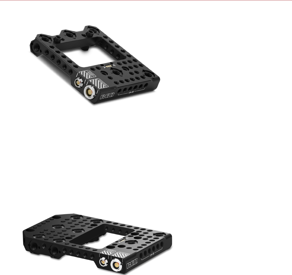
DSMC2 TACTICAL TOP PLATE
Figure: DSMC2 Tactical Top Plate
Machined from robust 7075 Aluminum, the DSMC2 Tactical Top Plate mounts to the top of your DSMC2 BRAIN to
provide 1/4-20 and 3/8-16 mounting points for RED and third-party accessories. This plate is specifically designed to
provide reliable and seamless functionality with existing DSMC2 battery modules, expanders, and accessories.
The DSMC2 Tactical Top Plate provides multiple ways to trigger record start/stop. First, the plate offers a 3-pin
POGO connector that allows you to mount a RED “smart” handle, extending the DSMC2 BRAIN’s intelligent handle
interface. Second, the plate also offers an unpowered 3-pin Fischer port, boasting the flexibility to interface with
compatible third-party start/stop triggers.
Additionally, the DSMC2 Tactical Top Plate extends the DSMC2 BRAIN's top LCD/EVF interface through a 16-Pin 1B
LCD/EVF connector. This additional connector allows you to remote mount a RED 16-Pin 1B-based display without
the use of a LCD/EVF Adaptor A.
DSMC2 PRODUCTION TOP PLATE
Figure: DSMC2 Production Top Plate
Designed to pair with the DSMC2 REDVOLT Expander and DSMC2 Production Module, the DSMC2 Production Top
Plate provides additional 1/4-20 and 3/8-16 mounting points for RED and third-party accessories. The DSMC2
Production Top Plate offers the same I/O as the DSMC2 Tactical Top Plate: a 3-pin POGO connector to mount a RED
"smart" handle; an unpowered 3-pin Fischer port for start/stop; and a 16-Pin 1B LCD/EVF connector. The plate is
compatible with other RED expanders and modules but may cover the P-Tap connector and Auto Boot on Power
switch, or interfere with the use of rear-mounted batteries.
C OPYR I GHT © 2 01 9 R ED. C OM , LLC 955- 0159_V 7. 1, R EV -G | 40
EPIC-W GEMINI OPERATION GUIDE

LENS MOUNTS
RED offers the following lens mounts:
ITEM PART NUMBER
DSMC S35 Mg PL Mount 2.0 725-0024
DSMC S35 Ti PL Mount (Captive) 725-0022
DSMC S35 Al Canon Mount (Captive) 725-0026
DSMC S35 Ti Canon Mount (Captive) 725-0032
DSMC S35 Al Nikon Mount 725-0006
DSMC S35 Ti Nikon Mount 725-0007
DSMC Al Leica M Mount (Captive) 725-0029
DSMC RED MOTION MOUNT S35 Ti PL 725-0012
DSMC RED MOTION MOUNT S35 Ti Canon (Captive) 725-0038
C OPYR I GHT © 2 01 9 R ED. C OM , LLC 955- 0159_V 7. 1, R EV -G | 41
EPIC-W GEMINI OPERATION GUIDE
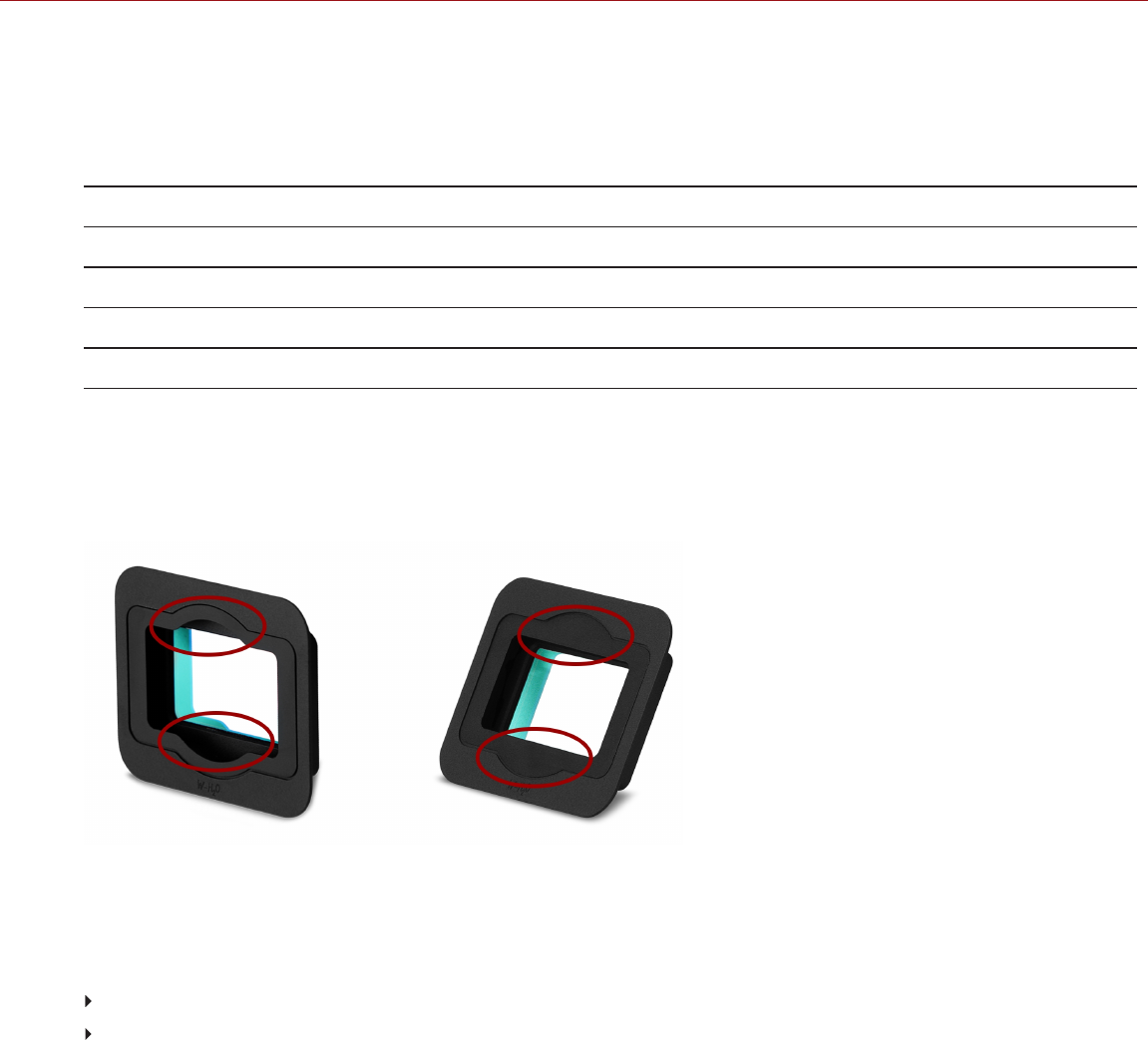
INTERCHANGEABLE OLPFS
The camera system includes intelligent, interchangeable optical low pass filters (OLPFs). The camera automatically
recognizes the OLPF type installed, eliminating the need to configure OLPF settings in the camera menu.
RED offers the following modular DSMC2 S35 interchangeable OLPFs:
ITEM PART NUMBER
DSMC2 S35 Standard OLPF 790-0513
DSMC2 S35 Skin Tone-Highlight OLPF 790-0511
DSMC2 S35 Low Light Optimized OLPF 790-0512
DSMC2 S35 H2O OLPF 790-0547
DSMC2 S35 OLPF REVISIONS AND COMPATIBILITY
DSMC2 S35 OPLFs shipped through October 2016 have curved glare stops at the top and bottom of the OLPF.
DSMC2 S35 OLPFs shipped after October 2016 have straight glare stops. The images below show the difference
between the original (curved glare stops) and modified (straight glare stops) DSMC2 S35 OLPFs:
Figure: Original DSMC2 S35 OLPF, Curved Glare Stops (Left); and Modified DSMC2 S35 OLPF, Straight Glare Stops
(Right)
The modified DSMC2 S35 OLPFs (straight glare stops) are incompatible with the following lenses due to their
protruding rear elements:
Leica Super-Elmar-M 18mm f/3.8 ASPH
Leica Super-Elmar-M 21mm f/3.4 ASPH
Other lenses that have very long protruding rear elements and require the Leica M Mount may not be fully compatible
with the modified DSMC2 S35 OLPFs (straight glare stops).
If your setup requires the lenses listed above, use the earlier revision of the DSMC2 S35 OLPF (the revision with the
curved glare stops). If you do not have the earlier revision of the DSMC2 S35 OLPF and need it, submit a Support
ticket at https://support.red.com.
C OPYR I GHT © 2 01 9 R ED. C OM , LLC 955- 0159_V 7. 1, R EV -G | 42
EPIC-W GEMINI OPERATION GUIDE

RAILS, MOUNTS, TACTICAL GEAR, AND CABLES
RED offers a wide variety of support gear, mounting platforms, cables, accessories, and other equipment. For more
information, visit the RED Store at www.red.com/store.
CAUTION: Attach accessories, plates, and rails directly to the mounting points on the BRAIN. While the DSMC2
REDVOLT Expander has mounting points for lightweight accessories, other expanders and modules are not designed
to support additional weight.
MAXIMUM SUPPORTED WEIGHTS
The table below lists the maximum weight each handle can support in specific configurations. Damage to handles or
other components of the camera system caused by using a handle to lift more than the specified weight is not
covered under warranty.
ITEM PART
NUMBER
CONFIGURATION MAXIMUM SUPPORTED
WEIGHT
DSMC2 Universal
Handle
790-0523 Attached directly to the camera body 30 lbs
DSMC2 Production Top
Handle
790-0657 One riser attached to a plate; handle
extension attached
40 lbs
Two risers attached to a plate; handle
extension attached
80 lbs
C OPYR I GHT © 2 01 9 R ED. C OM , LLC 955- 0159_V 7. 1, R EV -G | 43
EPIC-W GEMINI OPERATION GUIDE

C OPYR I GHT © 2 01 9 R ED. C OM , LLC 955- 0159_V 7. 1, R EV -G |44
EPIC-W GEMINI OPERATION GUIDE
CHAPTER 3:
BASIC OPERATIONS
POWER OPERATIONS
This section describes the basic power operations of the camera system.
For more information, see the DSMC Power Operation Guide, available at www.red.com/downloads.
NOTE: Modules, expanders, and lens mounts are NOT HOT SWAPPABLE, meaning you cannot remove or install
these items while the camera is turned on. Before installing or removing these items, you MUST turn off the camera.
Failure to do so may result in damage to the item or camera that is not covered under warranty.
WARNING: While third-party batteries may be mechanically compatible with the camera system, the manufacturer is
responsible for the performance and stability of third-party options, not RED®. Damage to the camera system or third-
party devices caused by using third-party power options is not covered under warranty. The camera may be unable to
determine and display the voltage or remaining battery capacity of third-party power options.
POWER PRIORITY
When multiple power sources are connected to the camera, power consumption is prioritized in this sequence:
1. Any power supply connected to the DC IN port on the expander
2. Any power supply connected to the DC IN port on a rear battery module
3. Rear battery
4. REDVOLT battery in the DSMC2® REDVOLT Expander
POWER CONSUMPTION
The camera draws approximately 3.3 A (50 W) when configured with the DSMC2 Base Expander, DSMC2 RED Touch
7.0" LCD, and RED MINI-MAG® 512GB.
Under typical conditions batteries provide the following operating time:
REDVOLT: Powers the camera and accessories for approximately 30 minutes.
REDVOLT-V: Powers the camera and accessories for approximately 35 minutes.
REDVOLT XL: Powers the camera and accessories for approximately 90 minutes.
RED BRICK: Powers the camera and accessories for approximately 120 minutes.
POWER STATUS
The power status of the current primary power source displays in the Lower Status Row of the graphical user interface
(GUI). Navigate to the Power In menu at Menu > Power > Power In for the status of all connected power sources.
For more information, go to "Power Menu" on page105.

APPROVED EXTERNAL DC POWER
The camera accepts input voltages of 11.5 V to 17 V DC, and can draw a maximum current of 9 A. The camera can be
powered continuously by connecting one (1) of the following to an attached module or expander:
Included RED power adaptor
XLR DC power source: Use the 4-PIN XLR-TO-4-PIN 2B POWER CABLE (10') or 3-PIN XLR-TO-4-PIN 2B
POWER CABLE (10') to connect to the DC-IN port to third-party block batteries, such as Anton Bauer VCLX or
Bebob Cube 1200
TURN ON THE CAMERA
NOTE: If you have just turned off the camera, wait at least three (3) seconds before turning the camera back on.
1. Attach a power source to the camera.
2. Press and release the PWR/REC key on the right side of the camera.
The Power Status LED illuminates amber as the camera turns on.
The Power Status LED illuminates green to confirm that the camera is turned on and ready to use.
TURN OFF THE CAMERA
Use one of the following methods to turn off the camera:
Go to Menu > Power and select Shutdown.
Press and hold PWR/REC until the Shutting Down... notification shows on the display.
NOTE: The camera turns off automatically if the supply voltage drops to 11.5 V.
C OPYR I GHT © 2 01 9 R ED. C OM , LLC 955- 0159_V 7. 1, R EV -G | 45
EPIC-W GEMINI OPERATION GUIDE
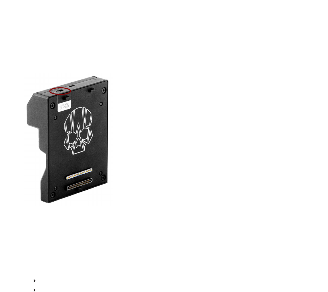
AUTO BOOT ON POWER
The DSMC2 Jetpack Expander, DSMC2 Jetpack-SDI Expander, DSMC2 REDVOLT Expander, DSMC2 V-Lock I/O
Expander, and DSMC2 Production Module feature a selector switch that enables the camera to automatically boot
when power is provided via the DC IN connector on the device. The Auto Boot on Power switch (identified by a line or
a white star) is located on top of the device.
When Auto Boot on Power is enabled, the camera disables all power sources that are not the DC IN connector on the
expander or module, including batteries and the DC IN connectors on any other modules.
Figure: Auto Boot on Power Switch
ENABLE AUTO BOOT ON POWER
1. Toggle the Auto Boot on Power switch to On (identified by a line or a white star).
2. Connect a power source to the DC IN connector.
The camera turns on automatically.
3. Use one of the following methods to turn off the camera:
Go to Menu > Power and select Shutdown.
Press and hold PWR/REC until the Shutting Down... notification shows on the display.
NOTE: Simply disconnecting the power source may result in data loss.
DISABLE AUTO BOOT ON POWER
1. Toggle the Auto Boot on Power switch to Off (identified by a circle or a black star).
The camera will not turn on automatically.
C OPYR I GHT © 2 01 9 R ED. C OM , LLC 955- 0159_V 7. 1, R EV -G | 46
EPIC-W GEMINI OPERATION GUIDE

CONFIGURE YOUR CAMERA
This section describes common options for configuring your camera system.
DSMC2 SIDEKICK: INSTALL/REMOVE
INSTALL THE DSMC2 SIDEKICK
This section applies to the following items:
DSMC2™ SIDEKICK (Forged CF)
DSMC2 SIDEKICK (Woven CF)
DSMC2 SIDEKICK (Magnesium)
NOTE: Each DSMC2 SIDEKICK is compatible with all DSMC2 cameras.
WARNING: Before installing or removing this item, you MUST turn off the camera.
REQUIRED TOOL(S): T10 TORX® driver
1. Turn off the camera.
2. Use a T10 TORX driver to remove the four (4) screws on the BRAIN® side plate (if the side plate is installed).
3. Remove the BRAIN side plate (if the side plate is installed).
4. Place the DSMC2 SIDEKICK in the slot where the lip of the BRAIN side plate was installed.
5. Press the DSMC2 SIDEKICK down flush along the side of camera.
6. Tighten the four (4) captive screws in a cross pattern (“X” pattern) using a T10 TORX driver. DO NOT FULLY
TIGHTEN.
7. Fully tighten the four (4) screws in a cross pattern (“X” pattern) using a T10 TORX driver.
WARNING: DO NOT OVERTIGHTEN.
REMOVE THE DSMC2 SIDEKICK
This section applies to the following items:
DSMC2 SIDEKICK (Forged CF)
DSMC2 SIDEKICK (Woven CF)
DSMC2 SIDEKICK (Magnesium)
NOTE: Each DSMC2 SIDEKICK is compatible with all DSMC2 cameras.
WARNING: Before installing or removing this item, you MUST turn off the camera.
REQUIRED TOOL(S): T10 TORX® driver
1. Turn off the camera.
2. Use a T10 TORX driver to loosen the four (4) captive screws attaching the DSMC2 SIDEKICK to the camera.
3. Remove the DSMC2 SIDEKICK from the camera.
C OPYR I GHT © 2 01 9 R ED. C OM , LLC 955- 0159_V 7. 1, R EV -G | 47
EPIC-W GEMINI OPERATION GUIDE

INSTALL THE DSMC2 SIDE HANDLE
WARNING: Before installing or removing this item, you MUST turn off the camera.
REQUIRED TOOL(S): T10 TORX driver (if a SIDEKICK Cover or DSMC2 SIDEKICK is installed), M2.5 hex key
1. Turn off the camera.
2. If a SIDEKICK Cover or DSMC2 SIDEKICK is installed, remove the device:
A. Use a T10 TORX driver to remove the four (4) screws on the SIDEKICK Cover or DSMC2 SIDEKICK.
B. Remove the SIDEKICK Cover or DSMC2 SIDEKICK.
3. Place the DSMC2 Side Handle in the slot where the lip of the SIDEKICK Cover was installed.
4. Press the DSMC2 Side Handle down flush along the side of camera.
5. Tighten the three (3) captive screws and the thumbscrew (in the lower left corner) using an M2.5 hex key. DO NOT
FULLY TIGHTEN.
NOTE: If you are unable to reach the thumbscrew with a hex key, hand-tighten the thumbscrew.
6. Fully tighten the three (3) screws and the thumbscrew using an M2.5 hex key.
WARNING: DO NOT OVERTIGHTEN.
NOTE: If you are unable to reach the thumbscrew with a hex key, hand-tighten the thumbscrew.
REMOVE THE DSMC2 SIDE HANDLE
WARNING: Before installing or removing this item, you MUST turn off the camera.
REQUIRED TOOL(S): M2.5 hex key
1. Turn off the camera.
2. Use an M2.5 hex key to loosen the three (3) captive screws and the thumbscrew (in the lower left corner).
NOTE: If you are unable to reach the thumbscrew with a hex key, loosen the thumbscrew by hand.
3. Remove the DSMC2 Side Handle from the camera.
INSTALL THE DSMC2 SIDE HANDLE GRIP
NOTE: You may replace the original grip of the DSMC2 Side Handle with a third-party grip. However, RED does not
test third-party grips, and cannot confirm if the third-party device will have the same functionality, quality, or strength
as the original grip included by RED in the DSMC2 Side Handle. Damage to the DSMC2 Side Handle or other
components of the camera system caused by using third-party accessories is not covered under warranty.
REQUIRED TOOL(S): 5 mm hex key
1. Place the original RED grip at the bottom of the DSMC2 Side Handle.
2. Use a 5 mm hex key to install the orignal M6 x 90 mm screw in the bottom of the grip.
C OPYR I GHT © 2 01 9 R ED. C OM , LLC 955- 0159_V 7. 1, R EV -G | 48
EPIC-W GEMINI OPERATION GUIDE

DSMC2 EXPANDER: INSTALL/REMOVE
INSTALL A DSMC2 EXPANDER
This section applies to the following items:
DSMC2 Base Expander
DSMC2 V-Lock I/O Expander
DSMC2 REDVOLT Expander
DSMC2 Jetpack Expander
DSMC2 Jetpack-SDI Expander
WARNING: Before installing or removing this item, you MUST turn off the camera.
WARNING: When installing and removing a DSMC2 REDVOLT Expander, ensure that a REDVOLT battery is NOT
installed in the expander. Damage to the REDVOLT or camera system caused by failing to remove the REDVOLT
during installation/removal is not covered under warranty.
REQUIRED TOOL(S): T20 TORX driver
1. Turn off the camera.
2. Position the expander on the rear of the camera, aligning the connector on the front of the expander with the
connector on the rear of the camera.
3. Apply pressure and tighten the four (4) captive screws in a cross pattern (“X” pattern) approximately two (2) turns
each using a T20 TORX driver. DO NOT FULLY TIGHTEN.
4. Fully tighten the four (4) screws in a cross pattern (“X” pattern) using a T20 TORX driver.
WARNING: DO NOT OVERTIGHTEN.
REMOVE A DSMC2 EXPANDER
This section applies to the following items:
DSMC2 Base Expander
DSMC2 V-Lock I/O Expander
DSMC2 REDVOLT Expander
DSMC2 Jetpack Expander
DSMC2 Jetpack-SDI Expander
WARNING: Before installing or removing this item, you MUST turn off the camera.
WARNING: When installing and removing a DSMC2 REDVOLT Expander, ensure that a REDVOLT battery is NOT
installed in the expander. Damage to the REDVOLT or camera system caused by failing to remove the REDVOLT
during installation/removal is not covered under warranty.
REQUIRED TOOL(S): T20 TORX driver
1. Turn off the camera.
2. Loosen the four (4) captive screws in a cross pattern (“X” pattern) using a T20 TORX driver.
3. Remove the expander from the camera.
C OPYR I GHT © 2 01 9 R ED. C OM , LLC 955- 0159_V 7. 1, R EV -G | 49
EPIC-W GEMINI OPERATION GUIDE

DSMC2 POWER MODULES: INSTALL/REMOVE
DSMC2 power module options include:
DSMC2 REDVOLT XL Module
DSMC2 V-Lock Battery Module
DSMC2 Gold Mount Battery Module
DSMC2 Production Module
INSTALL THE DSMC2 POWER MODULE
The DSMC2 power modules mount to the rear of the following items:
BRAIN
DSMC2 Base Expander
DSMC2 REDVOLT Expander
WARNING: Before installing or removing this item, you MUST turn off the camera.
REQUIRED TOOL(S): T20 TORX driver
1. Turn off the camera.
2. Position the module on the rear of the camera or expander, aligning the connector on the front of the module with
the connector on the rear of the camera or expander.
3. Apply pressure and tighten the four (4) captive screws in a cross pattern (“X” pattern) approximately two (2) turns
each using a T20 TORX driver. DO NOT FULLY TIGHTEN.
4. Fully tighten the four (4) screws in a cross pattern (“X” pattern) using a T20 TORX driver.
WARNING: DO NOT OVERTIGHTEN.
REMOVE THE DSMC2 POWER MODULE
WARNING: Before installing or removing this item, you MUST turn off the camera.
REQUIRED TOOL(S): T20 TORX driver
1. Turn off the camera.
2. Loosen the four (4) captive screws in a cross pattern (“X” pattern) using a T20 TORX driver.
3. Remove the module from the camera or expander.
C OPYR I GHT © 2 01 9 R ED. C OM , LLC 955- 0159_V 7. 1, R EV -G | 50
EPIC-W GEMINI OPERATION GUIDE

DSMC2 TOP HANDLE AND DSMC2 OUTRIGGER HANDLE:
INSTALL/REMOVE
INSTALL THE DSMC2 TOP HANDLE OR DSMC2 OUTRIGGER HANDLE
WARNING: Before installing or removing this item, you MUST turn off the camera.
REQUIRED TOOL(S): 3/16" hex key
1. Turn off the camera.
2. Position the DSMC2 Top Handle or DSMC2 Outrigger Handle on top of the camera, aligning the connector on the
bottom of the handle with the connector on top of the camera.
3. Tighten the two (2) captive screws approximately two (2) turns each using a 3/16" hex key. DO NOT FULLY
TIGHTEN.
4. Fully tighten the two (2) screws using a 3/16" hex key.
WARNING: DO NOT OVERTIGHTEN.
REMOVE THE DSMC2 TOP HANDLE OR DSMC2 OUTRIGGER HANDLE
WARNING: Before installing or removing this item, you MUST turn off the camera.
REQUIRED TOOL(S): 3/16" hex key
1. Turn off the camera.
2. Loosen the two (2) captive screws using a 3/16" hex key.
3. Remove the DSMC2 Top Handle or DSMC2 Outrigger Handle from the camera.
C OPYR I GHT © 2 01 9 R ED. C OM , LLC 955- 0159_V 7. 1, R EV -G | 51
EPIC-W GEMINI OPERATION GUIDE
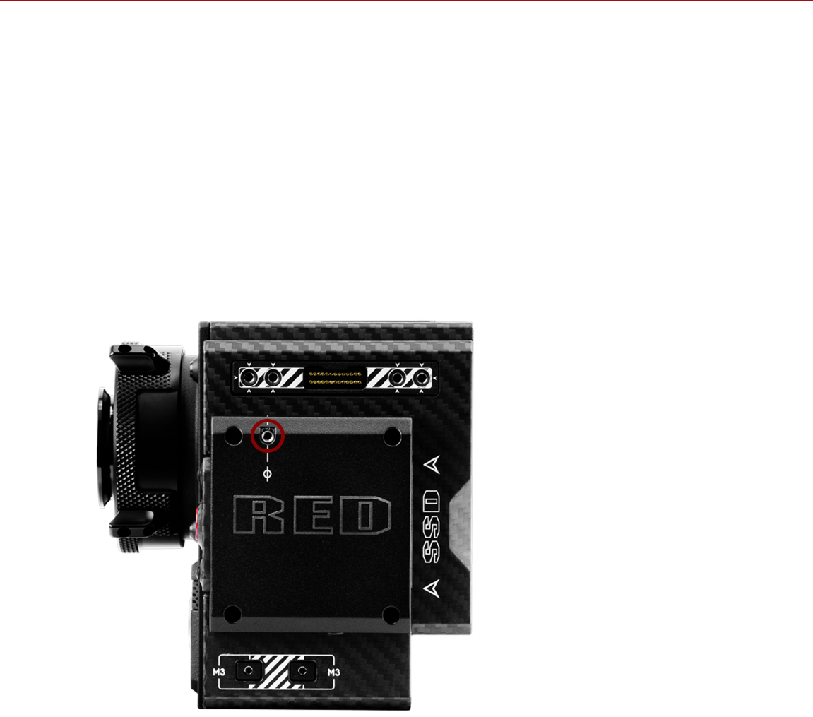
INSTALL THE FOCUS HOOK SCREW
The camera comes with a screw stored in the bottom of the media bay, called the focus hook screw. You can install
this screw in the Focus Hook Mounting point (along the sensor plane), and then pull focus from that location. You can
either attach measuring tape directly to the screw, or you can install a hook to the screw, and attach the measuring
tape to the hook.
To install the focus hook screw, follow the instructions below:
REQUIRED TOOL(S): Slotted screwdriver
NOTE: Cameras manufactured before December 2017 include a set screw installed in the Focus Hook Mounting Point.
If your camera has this screw, remove the screw with a 1.5 mm hex key before installing the focus hook screw.
1. Remove the focus hook screw from the Focus Hook Screw Storage Location on the media bay using a slotted
screwdriver.
2. Tighten the focus hook screw into the Focus Hook Mounting Point on the media bay using a slotted screwdriver.
WARNING: DO NOT OVERTIGHTEN.
Figure: Focus Hook Mounting Point
C OPYR I GHT © 2 01 9 R ED. C OM , LLC 955- 0159_V 7. 1, R EV -G | 52
EPIC-W GEMINI OPERATION GUIDE

INTERCHANGEABLE OLPF SYSTEM
WARNING: Read these instructions carefully and in their entirety before removing or installing an OLPF. Damage to
the OLPF module, camera, or sensor due to improper handling or use is not covered under warranty.
WARNING: Once an interchangeable OLPF is removed from the camera, the sensor is exposed. Improper handling of
the OLPF modules or camera during this procedure may compromise the installation or cause irreparable damage to
your camera or sensor.
WARNING: DO NOT allow any dirt or debris to enter the optical cavity.
WARNING: Use only DSMC2 S35 OLPFs. DO NOT other OLPFs.
SWAP AN INTERCHANGEABLE OLPF
REQUIRED TOOL(S): T20 TORX driver
1. Turn off the camera.
2. Remove any cables or accessories that may interfere with operations.
3. Loosen and remove the four (4) M4x0.7 x 8 mm lens mount screws in a cross pattern (“X” pattern) using a T20
TORX driver.
NOTE: Some lens mounts have captive screws that are not removable.
NOTE: Screw removal may require a large handle T20 TORX driver and additional leverage.
4. Remove the lens mount.
5. Use a damp, lint-free cloth to gently wipe down the area around the lens mount and OLPF module. Remove as
much dust and debris as possible.
6. Use a T20 TORX driver to turn the OLPF lock on the camera counter-clockwise by a third turn to the Unlock
position. DO NOT turn the indicator mark past the Unlock icon.
WARNING: DO NOT OVERTIGHTEN.
7. Remove the OLPF module and place it in its protective case.
8. Use an LED light to ensure that the optical cavity is clean and free from dust or debris.
9. Ensure the new OLPF module is clean and free of debris.
10. Install the new OLPF module straight into the optical cavity, keeping the front face of the OLPF module parallel to
the front of the camera.
NOTE: Inserting the OLPF module at an angle may cause it to not seat properly.
11. Use a T20 TORX driver to turn the OLPF lock on the camera clockwise by a third turn to the Lock position. DO
NOT turn the indicator mark past the Lock icon.
WARNING: DO NOT OVERTIGHTEN.
NOTE: If the lock does not turn easily, gently press down on the OLPF module while turning the lock.
12. Replace the lens mount.
13. Replace and loosely tighten the four (4) M4x0.7 x 8 mm lens mount screws in a cross pattern (“X” pattern) using a
T20 TORX driver. DO NOT FULLY TIGHTEN.
NOTE: Some lens mounts have captive screws that are not removable.
14. Fully tighten the four (4) lens mount screws in a cross pattern (“X” pattern) using a T20 TORX driver. DO NOT
exceed 350 in-oz, or damage may occur.
WARNING: DO NOT OVERTIGHTEN.
C OPYR I GHT © 2 01 9 R ED. C OM , LLC 955- 0159_V 7. 1, R EV -G | 53
EPIC-W GEMINI OPERATION GUIDE

USE A TRIPOD OR MONOPOD
This section describes the camera mounting points and mounting equipment for use with a tripod or monopod. The
camera is equipped with two (2) 3/8-16 mounting holes and one (1) 1/4-20 mounting hole on the bottom of the camera.
These mounting points are designed for use with a variety of mounting plates and hardware, to support tripods and
other support systems.
WARNING: Ensure that the tripod, monopod, or support system is designed and rated to handle the weight of your
camera configuration. RED is not responsible for any damage caused by using a tripod, monopod, mount, or support
system that does not provide sufficient support.
WARNING: DO NOT use excessive force to mount a support accessory, as this may damage the screw threading.
RED offers the following products for use with tripods and other support systems:
Item Part Number
Mounting Plate (DSMC) 790-0094
DSMC Quick Release Platform Pack 790-0183
Quick Release Platform Pack (Bolt-On) 790-0078
Quick Release Platform (Dovetail) 790-0079
Quick Release Platform (Mini) 790-0390
Dovetail Mounting Plate (Long) 790-0083
Dovetail Mounting Plate (Short) 790-0084
For more information, visit the RED store at www.red.com/store.
C OPYR I GHT © 2 01 9 R ED. C OM , LLC 955- 0159_V 7. 1, R EV -G | 54
EPIC-W GEMINI OPERATION GUIDE

VIDEO MONITOR OUTPUTS
NOTE: HD-SDI and HDMI® ports are only available on select DSMC2 expanders and modules. For more information,
go to "Input/Output Connectors" on page219.
The monitoring path converts RAW sensor data to a white balanced 12-bit depth 1920 x 1080 pixel RGB 4:4:4 video
signal. The signal may be modified using ISO, White Balance, or other RGB color space adjustments. The signal is
then scaled and gamma-corrected to provide monitor outputs at 10-bit depth in 4:2:2 YCC or 8-bit depth in 4:4:4
RGB.
The camera offers the following monitor outputs:
EVF/LCD: Supports a RED EVF or LCD display.
HD-SDI: Provides a 720p or 1080p output suitable for monitoring or recording to an external VTR or DDR device. It
may be configured for 10-bit LIN (VIDEO) or 10-bit LOG (FILM) encoded data.
HDMI: Provides a 480p, 720p, or 1080p output suitable for monitoring via a Windows® monitor or most HDTVs.
VIDEO MONITOR CATEGORIES
Video monitor outputs are separated into three (3) categories:
VIEWFINDER: The Upper Status Row, Live Action Area, and Lower Status Row display. Default output is the
EVF/LCD connector located on top of the camera. If an EVF or LCD is not connected, you can transfer the
VIEWFINDER output to either the HDMI or 3G-SDI (HD-SDI) output.
PROGRAM/Clean: None of the graphic overlays display.
PREVIEW: The Live Action Area and associated graphic overlays display.
For more information about changing the video monitor category of your monitor, go to "Monitor Mode" on page91.
C OPYR I GHT © 2 01 9 R ED. C OM , LLC 955- 0159_V 7. 1, R EV -G | 55
EPIC-W GEMINI OPERATION GUIDE

RECORD
Perform one of the following actions to begin recording:
Press PWR/REC on the camera.
Press REC on the media bay.
Press START/STOP on the DSMC2 Top Handle or DSMC2 Outrigger Handle.
Trigger start/stop with a compatible third-party trigger.
Double-tap the right 25% on an attached touchscreen display (when enabled).
NOTE: To enable Double-Tap Right 25% to Record, go "Advanced" on page94.
RECORD VIA HD-SDI OR HDMI
NOTE: Audio is not embedded in the MON-1 signal.
This section describes how to record via HD-SDI or HDMI through simultaneous record (recording to an SSD and an
external recorder at the same time) or external record only.
SIMULTANEOUS RECORD
NOTE: HD-SDI and HDMI ports are only available on select DSMC2 expanders and modules. For more information,
go to "Input/Output Connectors" on page219.
NOTE: The secondary LCD/EVF port and an HDMI/MON-1 port cannot be used at the same time. Go to "Monitor
Preferences" on page90.
You can record simultaneously to an external recorder and a RED SSD. To record simultaneously, follow the
instructions below:
1. Attach a DSMC2 expander or module that has an HD-SDI or HDMI port.
2. Connect the camera to an external recorder with an HD-SDI or HDMI cable.
3. Ensure that a formatted SSD is inserted in the camera.
4. Set up the HD-SDI or HDMI output:
A. Go to Menu > Monitoring > Monitors and select a monitor.
B. Select Clean from the Mode drop-down menu (otherwise the external recorder records the overlay).
C. Select the output resolution from the Resolution drop-down menu.
NOTE: The HDMI and HD-SDI maximum resolution is 1080p. For more information, go to "Record/Monitor Out
Ports" on page227.
5. Disable all False Colors (otherwise the external recorder records the False Colors). For more information, go to
"Tools" on page96.
6. If monitoring audio via a third-party monitor that supports audio, set up the monitor mix:
A. Go to Menu > Settings > Audio > Mix > Monitor Mix.
B. Adjust the input channels.
7. Go to Menu > Settings > Recording > Mode.
8. Select Local from the Storage drop-down menu.
9. Begin recording.
C OPYR I GHT © 2 01 9 R ED. C OM , LLC 955- 0159_V 7. 1, R EV -G | 56
EPIC-W GEMINI OPERATION GUIDE

EXTERNAL RECORD
NOTE: HD-SDI and HDMI ports are only available on select DSMC2 expanders and modules. For more information,
go to "Input/Output Connectors" on page219.
NOTE: The secondary LCD/EVF port and an HDMI/MON-1 port cannot be used at the same time. Go to "Monitor
Preferences" on page90.
You can record to an external recorder without recording to an SSD. To record to an external device only, follow the
instructions below:
1. Attach a DSMC2 expander or module that has an HD-SDI or HDMI port.
2. Connect the camera to an external recorder with an HD-SDI or HDMI cable.
3. Ensure the SSD is ejected.
4. Set up the HD-SDI or HDMI output:
A. Go to Menu > Monitoring > Monitors and select a monitor.
B. Select Clean from the Mode drop-down menu (otherwise the external recorder records the overlay).
C. Select the output resolution from the Resolution drop-down menu.
NOTE: The HDMI and HD-SDI maximum resolution is 1080p. For more information, go to "Record/Monitor Out
Ports" on page227.
5. Disable all False Colors (otherwise the external recorder records the False Colors). For more information, go to
"Tools" on page96.
6. If monitoring audio via a third-party monitor that supports audio, set up the monitor mix:
A. Go to Menu > Settings > Audio > Mix > Monitor Mix.
B. Adjust the input channels.
7. Go to Menu > Settings > Recording > Mode.
8. Select External from the Storage drop-down menu.
9. Begin recording.
C OPYR I GHT © 2 01 9 R ED. C OM , LLC 955- 0159_V 7. 1, R EV -G | 57
EPIC-W GEMINI OPERATION GUIDE

C OPYR I GHT © 2 01 9 R ED. C OM , LLC 955- 0159_V 7. 1, R EV -G |58
EPIC-W GEMINI OPERATION GUIDE
CHAPTER 4:
BASIC MENUS AND CONTROLS
GUI MENU INTRODUCTION
This section describes the structure and layout of the graphical user interface (GUI) that overlays the video monitor
signal. Advanced GUI menu controls enable convenient access to menus, overlays, and other critical camera
information. Functionality varies based on monitor output type and firmware version. The GUI menu is separated into
three (3) main sections:
Figure: GUI Control Menu
# ITEM DESCRIPTION
1 Upper Status Row
(Basic Menu)
Easy access to primary camera capture parameters. Go to "Upper Status Row (Basic
Menu)" on the next page.
2 Live Action Area Live camera recording view, overlays, guides, and more. Go to "Live Action Area" on
page63.
3 Lower Status Row Critical camera parameters, record/playback modes, media and power status, and audio
meter. Go to "Lower Status Row" on page65.
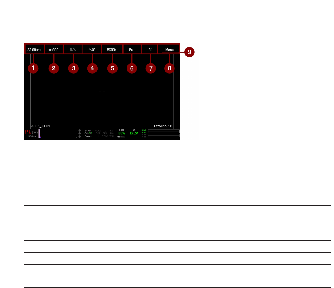
UPPER STATUS ROW (BASIC MENU)
The Upper Status Row displays basic project parameters. The currently selected parameter in the Upper Status Row
is underlined with a red bar. The Upper Status Row is also known as the Basic Menu.
Figure: Upper Status Row
The Upper Status Row includes the following GUI elements:
# ITEM DESCRIPTION DETAILS
1 Frame Rate (fps) Recording frame rate "Frame Rate" on page117
2 ISO Camera sensitivity "ISO" on page86
3 Aperture Lens aperture (F stop) information "Aperture" on page61
4 Exposure (Shutter) Integration time or shutter angle "Exposure/Shutter" on page118
5 Color Temperature White balance and Tint "White Balance" on page85
6 Resolution Record resolution "Format" on page120
7 REDCODE®REDCODE compression setting "REDCODE" on page62
8 Menu Access advanced settings "Advanced Menus" on page81
9 Cursor Indicates currently selected Upper Status Row element N/A
C OPYR I GHT © 2 01 9 R ED. C OM , LLC 955- 0159_V 7. 1, R EV -G | 59
EPIC-W GEMINI OPERATION GUIDE
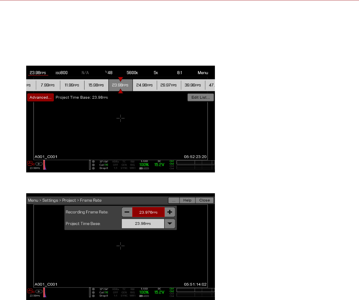
ACCESS ADVANCED MENUS
For every Upper Status Row item, you can select the Advanced... button to access the related menu in the Advanced
Menus.
For example, select Advanced... in the Frame Rate menu to open Menu > Settings > Project > Frame Rate.
For more information about Advanced Menus, go "Advanced Menus" on page81.
Figure: Select "Advanced..." Button
Figure: Advanced Menu
C OPYR I GHT © 2 01 9 R ED. C OM , LLC 955- 0159_V 7. 1, R EV -G | 60
EPIC-W GEMINI OPERATION GUIDE
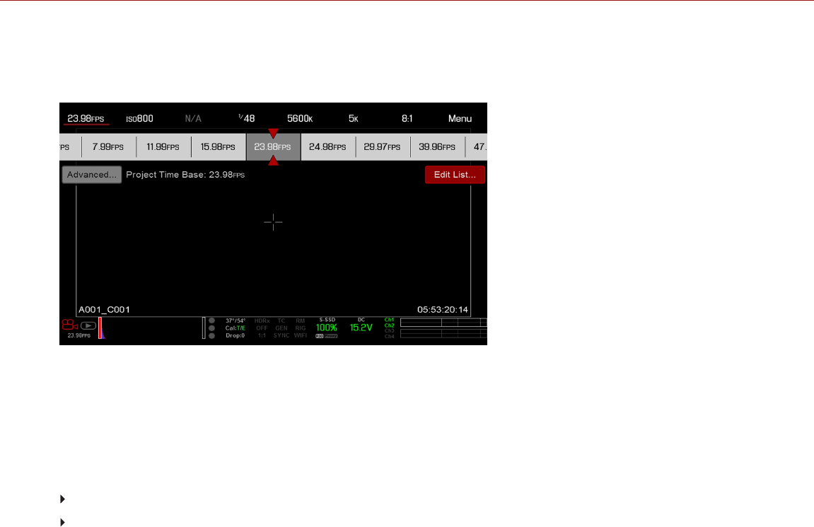
FEATURE: EDIT LIST
Select the Edit List... button in the Upper Status Row menus to change the values that display for each setting. For
example, if you open the Frame Rate menu and select Edit List..., the camera lets you add or remove values.
Figure: Select "Edit List..." Button
APERTURE
The aperture (also known as the T stop or F stop) parameter displays when a compatible mount and lens are installed.
The aperture controls the depth of field of the image and, in combination with the shutter speed/angle setting, controls
the amount of light that reaches the sensor (exposure).
Increasing the aperture to a higher number increases the depth of field, but reduces the exposure (brightness).
Decreasing the aperture to a lower number decreases the depth of field, but increases the exposure (brightness).
RED DSMC PL MOUNT INSTALLED
The current aperture of the attached lens displays when a DSMC ® PL mount is installed and a supported lens
equipped with Cooke® S4/i® system is attached.
DSMC NIKON MOUNT AND CANON MOUNT INSTALLED
The Aperture menu is visible when a DSMC Nikon® Mount, DSMC Canon® Mount, or DSMC RED® MOTION MOUNT
S35 Ti Canon (Captive) is installed and a supported lens is attached. This enables you to adjust the aperture of the
attached lens.
Select the Advanced... button to access the Menu > Settings > Setup > Lens screen. For more information, go to
"Lens" on page152.
C OPYR I GHT © 2 01 9 R ED. C OM , LLC 955- 0159_V 7. 1, R EV -G | 61
EPIC-W GEMINI OPERATION GUIDE

REDCODE
Select the target REDCODE compression ratio for your project.
If the camera is able to achieve the target compression ratio, the compression ratio displays in white. If the camera is
unable to achieve the target compression ratio, the compression ratio displays in yellow, and the camera uses the next
possible compression ratio.
The current compression ratio is automatically recalculated when changes are made to the project resolution, aspect
ratio, anamorphic setting, frame rate, HDRX® mode, media, or the target REDCODE compression ratio.
The RECODE compression affects the overall quality of the footage. A lower compression (for example: 2:1) increases
the quality of the footage, while a higher compression (for example: 22:1) lowers the quality.
For more information, go to "R3D File Format and REDCODE" on page10.
REDCODE range is 2:1 to 22:1. Default is 8:1.
For maximum available REDCODE values, see the DSMC Media Operation Guide at www.red.com/downloads.
C OPYR I GHT © 2 01 9 R ED. C OM , LLC 955- 0159_V 7. 1, R EV -G | 62
EPIC-W GEMINI OPERATION GUIDE
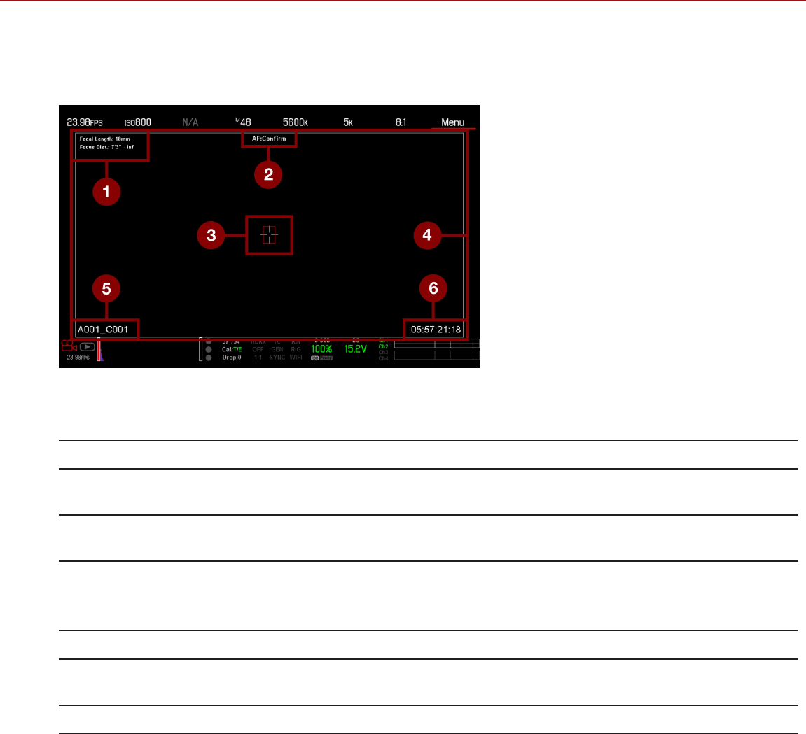
LIVE ACTION AREA
The Live Action Area contains the recorded image area, Look Around area, and various overlays. The color of each
overlay can be customized to maximize the contrast between the guide(s) and scene being captured.
Figure: Live Action Area
The Live Action Area includes the following GUI elements:
# ITEM DESCRIPTION DETAILS
1 Lens Information Lens information when using supported Canon®,
Nikon®, or Cooke® lenses
"Lens Information" on the
next page
2 AF Status Currently selected auto focus mode "Focus Menu" on
page137
3 Center Crosshair and Spot
Focus Guide
Crosshair: Center of selected guide
Reference guides: Safe Action/Safe Title, Picture
Center, Grid Overlay
"Guides" on page102
4 Frame Guides Record or sensor projection area "Guides" on page102
5 Clip Filename Filename of the clip being recorded, or filename of the
next clip to be recorded
N/A
6 Timecode Value Current timecode value "Timecode" on page174
C OPYR I GHT © 2 01 9 R ED. C OM , LLC 955- 0159_V 7. 1, R EV -G | 63
EPIC-W GEMINI OPERATION GUIDE

LENS INFORMATION
This section describes the lens information displays when a supported lens is attached.
PL LENSES
Displays the focal length and focal distance when a DSMC PL mount is installed and a lens with the Cooke S4/i
system (or equivalent) is attached. For more information, go to "Lens" on page152.
CANON AND NIKON LENSES
The camera displays the focal length and focal distance when a DSMC Canon Mount or a DSMC Nikon Mount is
installed and an electronically supported lens is attached. When AF is set to Manual or Confirm mode, the focal
distance displays as a pair of Near–Far distances. When in AF mode, an estimated focus distance displays. The focal
length and focal distance values and range vary depending on the attached lens. When the focal length of the lens
changes, the current values displays. For more information, go to "Lens" on page152.
C OPYR I GHT © 2 01 9 R ED. C OM , LLC 955- 0159_V 7. 1, R EV -G | 64
EPIC-W GEMINI OPERATION GUIDE
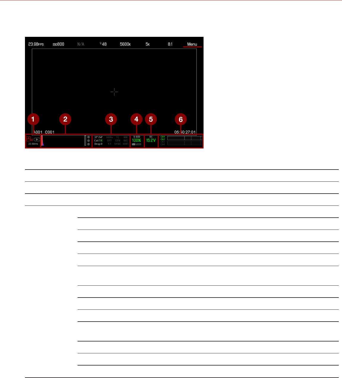
LOWER STATUS ROW
The Lower Status Row provides access to key system information and camera values.
Figure: Lower Status Row
# ITEM SUB-ITEM/DESCRIPTION DETAILS
1 Camera Mode Swipe up to toggle Motion/Stills/Playback modes "Camera Mode" on page67
2 Histogram Histogram; tap to open the Tools menu "Histogram" on page69
3 Project Status
Indicators
Tap to open the Project Status menu "Project Status" on page156
Camera sensor and core temperature "Sensor Calibration" on page159
Cal: T/E "CAL: T/E Indicator" on page70
HDRX®: Displays when HDRX mode is on "HDRX Menu" on page136
False Color Mode: Displays modes "False Color Modes" on page96
Magnify mode "Display Modes: Magnify" on
page98
Timecode "TC Indicator" on page70
Genlock "GEN Indicator" on page70
Sync "SYNC Indicator" on page70
RM "RM (Remote) Indicator" on
page70
LAN "LAN Indicator" on page71
RIG: Indicates 3D rig metadata is present N/A
WIFI: Indicates wireless connection "WiFi Indicator" on page71
C OPYR I GHT © 2 01 9 R ED. C OM , LLC 955- 0159_V 7. 1, R EV -G | 65
EPIC-W GEMINI OPERATION GUIDE

# ITEM SUB-ITEM/DESCRIPTION DETAILS
4 Media Status Media location and remaining capacity; file type (R3D and/or
third-party proxy); tap to open the Media Menu
"Media Menu" on page113
5 Power Status DC voltage or remaining battery capacity; tap to open the
Power menu
"Power Status" on page71
6 Audio Meter Audio input and volume; tap to open the Audio menu "Audio Meter (VU Meter)" on
page170
C OPYR I GHT © 2 01 9 R ED. C OM , LLC 955- 0159_V 7. 1, R EV -G | 66
EPIC-W GEMINI OPERATION GUIDE

CAMERA MODE
The Camera Mode allows you to seamlessly toggle between Motion mode, Stills mode, and Playback. To select a
camera mode, select the Camera Mode icon in the Lower Status Bar, swipe up, and select a camera mode.
NOTE: Setting adjustments made in Stills mode do not affect the settings in Motion mode, and vice versa.
You can select the following camera modes:
"Motion Mode" below
"Stills Mode" on the next page
"Playback " on page108
MOTION MODE
Motion mode optimizes your camera settings for capturing motion. This mode defaults the camera to Continuous
Record. Motion mode includes the following features:
Motion recording modes:
"Continuous Record" on page124
"Internal Timelapse Timer" on page124
"Frame Trigger" on page125
"Speed Ramp Mode" on page125
"REDCODE Burst" on page126
Swipe-Up Shortcuts
Camera Mode
False Color
Status
Media
Power
Audio
Default Motion Preset (RED)
NOTE: For more information, go to "Swipe-Up Menu" on page74.
C OPYR I GHT © 2 01 9 R ED. C OM , LLC 955- 0159_V 7. 1, R EV -G | 67
EPIC-W GEMINI OPERATION GUIDE

STILLS MODE
Stills mode optimizes your camera settings for capturing stills. Stills mode includes the following features:
Stills recording modes:
"Multi-Shot" on page127
"Motion + Stills" on page128
Swipe-Up Shortcuts:
False Color
Status
Media
Power
Auto Focus
Auto Exposure
Record Mode
Default Stills Preset (RED)
For more information, go to "Swipe-Up Menu" on page74.
C OPYR I GHT © 2 01 9 R ED. C OM , LLC 955- 0159_V 7. 1, R EV -G | 68
EPIC-W GEMINI OPERATION GUIDE
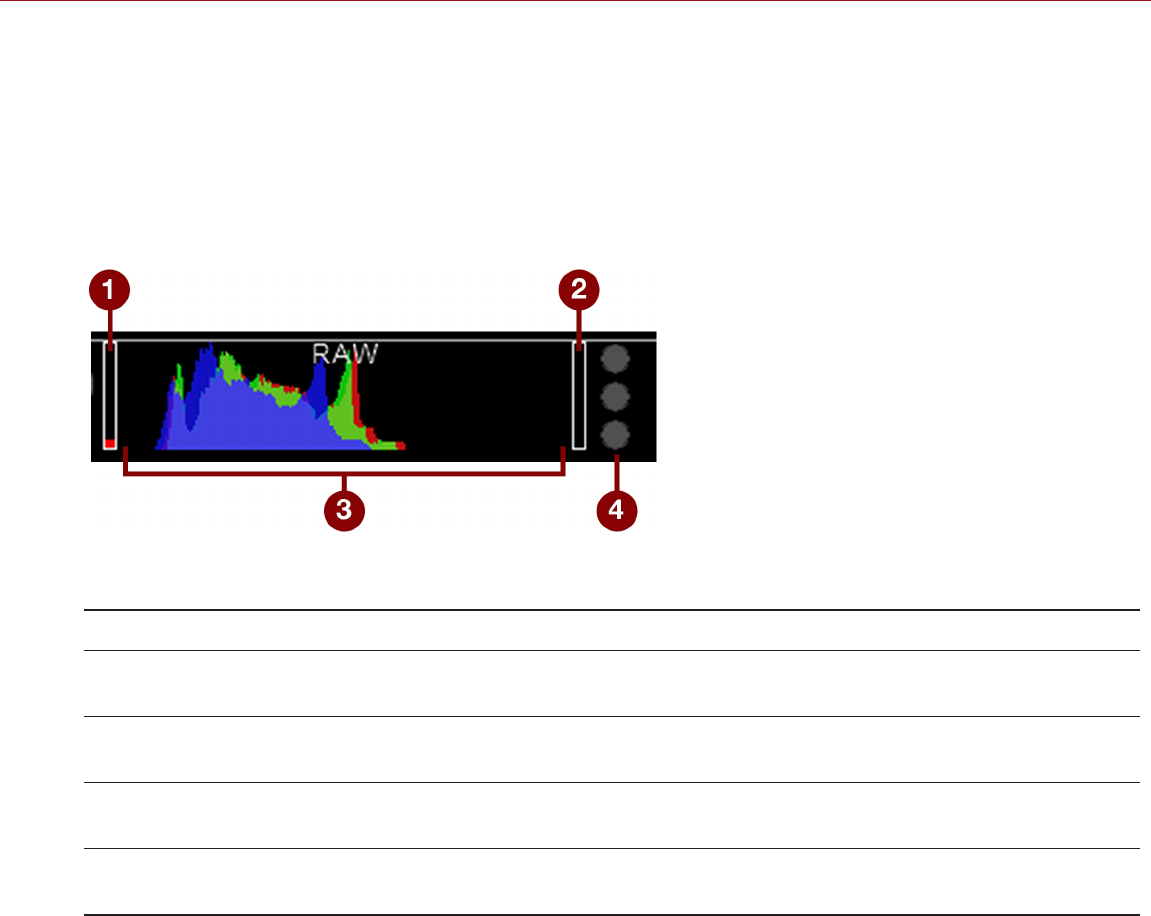
HISTOGRAM
NOTE: The sharpness setting affects the Histogram, RAW Level Bars, and RAW Clip Meter. For more information, go
to "Output Sharpness" on page94.
This section describes the elements that comprise the Histogram section in the Lower Status Row. This section of the
GUI helps ensure that recorded footage is properly exposed.
Tap the Histogram in the Lower Status Row to access the Tools menu. For more information, go to "Tools" on
page96.
Figure: Histogram (Exposure)
# ITEM DESCRIPTION
1 RAW Level
Bar (left)1Also known as a “goal post”. Displays the amount of pixels in the image that are underexposed
(noise)
2 RAW Level
Bar (right)1Also known as a “goal post”. Displays the amount of pixels in the image that are overexposed
(clipping)
3 RGB
Histogram
Provides a visual representation of exposure and sensor data levels for red, green, and blue
channels; meter is affected by White Balance, ISO, and VIEW/LOOK settings
4 RAW Clip
Meter
Also known as “traffic lights”. Provides a visual representation of exposure and sensor data levels
for red, green, and blue channels; Circles (traffic lights) will light up when clipping occurs
1. The RAW Level Bars represent 1/4 of the total pixels in the image, and illustrate the number of pixels that are noisy or clipped in relation to the
total number of pixels. For example, if the left RAW Level Bar is 1/8 of the total height, that means that approximately 1/32 of the total pixels in
the total image are at an exposure level that is at risk of displaying noise when pushed to higher ISO or FLUT® values in post production.
PROJECT STATUS INDICATORS
This section describes the colors and behavior of the Project Status indicators in the Lower Status Row. Tap the
Project Status indicators in the Lower Status Row to access the Project Status menu. For more information, go to
"Project Status" on page156.
C OPYR I GHT © 2 01 9 R ED. C OM , LLC 955- 0159_V 7. 1, R EV -G | 69
EPIC-W GEMINI OPERATION GUIDE

CAL: T/E INDICATOR
The CAL: T/E indicator shows changes to temperature (T) or exposure (E) in relation to the active calibration map. If the
temperature or exposure change significantly, calibrate the sensor at the desired temperature and exposure. Failure to
properly calibrate the sensor may reduce image quality.
Green: Sensor temperature or exposure are properly calibrated for current settings.
Yellow: Slight change in sensor temperature or exposure.
Red: Significant change in sensor temperature or exposure.
The – and + indicate whether the sensor temperature or exposure has decreased or increased, respectively.
NOTE: T and E indicators change colors independently of each other.
TC INDICATOR
The TC indicator shows the current timecode status.
Grey: No analog timecode is detected.
Red: Analog timecode is detected but not enabled.
Green: Analog timecode is used to jam the time of day timecode.
For more information, go to "Timecode, Genlock, Multi-Camera Setup" on page174.
GEN INDICATOR
The GEN indicator shows the current genlock status.
Grey: No genlock signal is detected, or the signal cannot cross-lock to project (24.00 fps vs. 23.98 fps).
Red: During process of sync, or genlock is lost while recording.
Green: A genlock signal matching the current HD-SDI monitor rate is locked.
Yellow: Timing is cross-locked to compatible but not matching monitor rate. For example, genlock is 24.00 fps,
and HD-SDI monitor rate is 25.00 fps.
NOTE: When the GEN indicator is yellow, DO NOT perform 3D operation. This warns that genlock source settings and
camera settings are not aligned, so phasing of the sync between cameras is not guaranteed.
For more information, go to "Timecode, Genlock, Multi-Camera Setup" on page174.
SYNC INDICATOR
The SYNC indicator shows the current sensor sync status, based on genlock.
Grey: The sensor sync mode is not set to genlock.
Red: The sensor sync mode is set to genlock, but is not locked to a genlock signal. This may occur if genlock or
sensor sync is lost while recording.
Green: The sensor sync mode and HD-SDI monitor rate are locked to a compatible genlock signal.
For more information, go to "Timecode, Genlock, Multi-Camera Setup" on page174.
RM (REMOTE) INDICATOR
The RM indicator displays if the camera is linked to a third-party remote application, such as foolcontrol.
C OPYR I GHT © 2 01 9 R ED. C OM , LLC 955- 0159_V 7. 1, R EV -G | 70
EPIC-W GEMINI OPERATION GUIDE

LAN INDICATOR
NOTE: The GIG-E port is only available on the DSMC2® REDVOLT Expander, DSMC2 Jetpack-SDI Expander, and
DSMC2 Production Module. For more information, go to "Input/Output Connectors" on page219.
The LAN indicator shows the current status of an external LAN connection through the Gig-E port.
Grey: External control of the camera is not enabled.
Green: Ethernet is enabled.
WIFI INDICATOR
The WiFi indicator shows the wireless connectivity status.
Grey: Wireless is disabled.
Yellow: Wireless is not connected.
Green: Wireless is enabled.
For more information, go to "Wireless Connection" on page145.
POWER STATUS
The Power Status element displays the current supply voltage or remaining battery capacity. Tap the Power Status
element to access the Power menu. For more information, go to "Power Menu" on page105.
DC IN SUPPLY VOLTAGE
When powering the camera via DC power, the current voltage displays. When powering the camera using batteries, the
remaining battery capacity displays. The remaining capacity is indicated by the following colors:
Green: 12.0 V and up
Yellow: 11.8 V to 11.9 V
Red: 11.6 V to 11.7 V
NOTE: The camera turns off automatically if the supply voltage drops to 11.5 V.
BATTERY TIME REMAINING
When using a REDVOLT, REDVOLT-V, or REDVOLT XL battery, the power status displays the location of the power
source and the remaining battery capacity.
The color of the displayed battery capacity represents the amount of time remaining:
Green: >10 minutes
Yellow: 5 to 10 minutes
Red: <5 minutes
C OPYR I GHT © 2 01 9 R ED. C OM , LLC 955- 0159_V 7. 1, R EV -G | 71
EPIC-W GEMINI OPERATION GUIDE
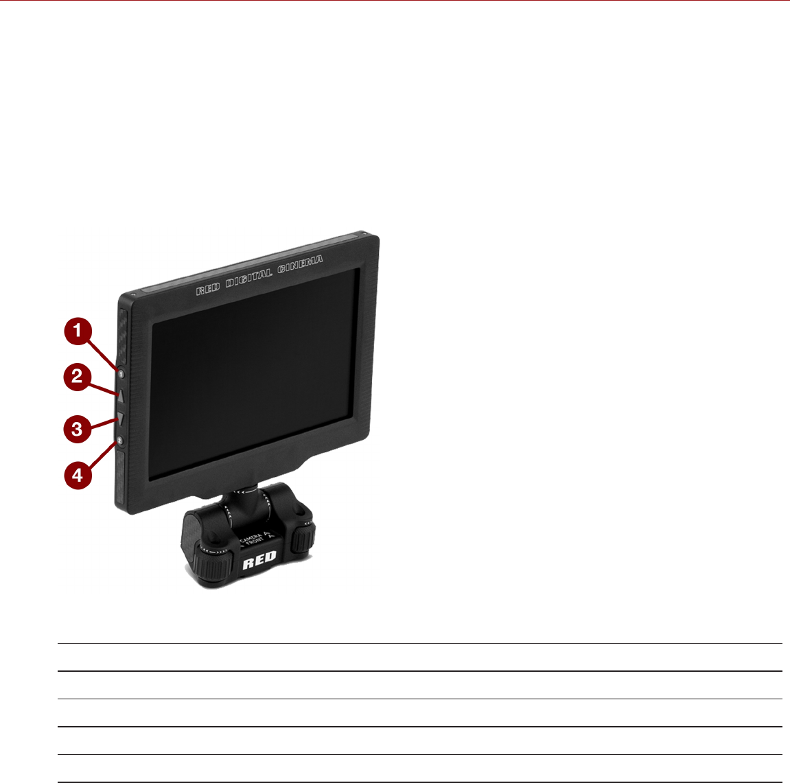
NAVIGATION CONTROLS
This section describes basic controls for navigating the camera menus.
TOUCHSCREEN NAVIGATION
You can control certain settings and navigate the camera menu using buttons and gestures on the RED Touch
displays.
RED TOUCH DISPLAY BUTTONS
RED Touch displays offer intuitive menu control and four (4) programmable buttons.
Figure: DSMC2 RED Touch 7.0" LCD
# RED TOUCH BUTTON DESCRIPTION
1 User Key 1 Magnify: Toggle
2 Up Button Increase display brightness
3 Down Button Decrease display brightness
4 User Key 2 Toggle Exposure Mode on/off
NOTE: RED Touch display keys are programmable. For more information, go to "Key Mapping" on page142.
C OPYR I GHT © 2 01 9 R ED. C OM , LLC 955- 0159_V 7. 1, R EV -G | 72
EPIC-W GEMINI OPERATION GUIDE

RED TOUCH DISPLAY GESTURES
Navigate the menus using a touchscreen by using the following gestures:
Tap: Tap has many functions:
Tap to select a Basic Menu, submenu, or button.
If a menu is open, tap anywhere outside the menu to save any changes and close the menu.
Tap the right or left regions of the touchscreen to access the programmable soft keys.
Swipe: Swipe to select different values in spinners or drop-down menus. For more information, go to "Swipe-Up
Menu" on the next page.
Double-Tap: If the monitor is in Clean mode, changes to Overlay mode.
Hold: Tap and hold an icon to bring up an advanced interface display.
Pinch: Move two (2) fingers apart/together to increase/decrease the size of the image. By default, this gesture is
disabled.
For more information, go to "Advanced" on page94.
C OPYR I GHT © 2 01 9 R ED. C OM , LLC 955- 0159_V 7. 1, R EV -G | 73
EPIC-W GEMINI OPERATION GUIDE
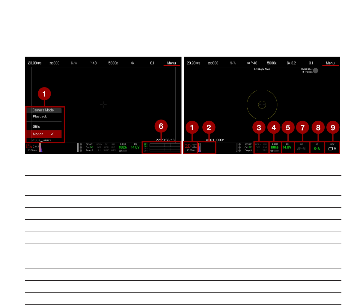
SWIPE-UP MENU
The Swipe-Up Menu is available in the Lower Status Row on RED Touch displays and provides Swipe-Up Shortcuts
for Motion mode, Stills mode, and Playback. For example, select the Camera Mode icon in the Lower Status Bar,
swipe up, and select a Camera Mode. For more information about Stills mode and Motion mode, go to "Camera
Mode" on page67.
Figure: Swipe Up Menu
# SWIPE-UP
SHORTCUT
DESCRIPTION MODE
1 Camera Mode Select Playback, Motion, or Stills Motion,Stills
2 False Color Select a false color mode; go to "False Color Modes" on page96 Motion,Stills
3 Status View detailed status information Motion,Stills
4 Media View as Percentage or Time Remaining, eject media, view clip thumbnails Motion,Stills
5 Power View as Percentage, Time Remaining, or Voltage Motion,Stills
6 Audio Select Audio settings Motion
7 Auto Focus Set Zone, Size, and Mode Stills
8 Auto Exposure Set Exp Comp, Speed, Metering, Priority, and Mode Stills
9 Record Mode Select Multi-Shot or Motion + Stills Stills
C OPYR I GHT © 2 01 9 R ED. C OM , LLC 955- 0159_V 7. 1, R EV -G | 74
EPIC-W GEMINI OPERATION GUIDE
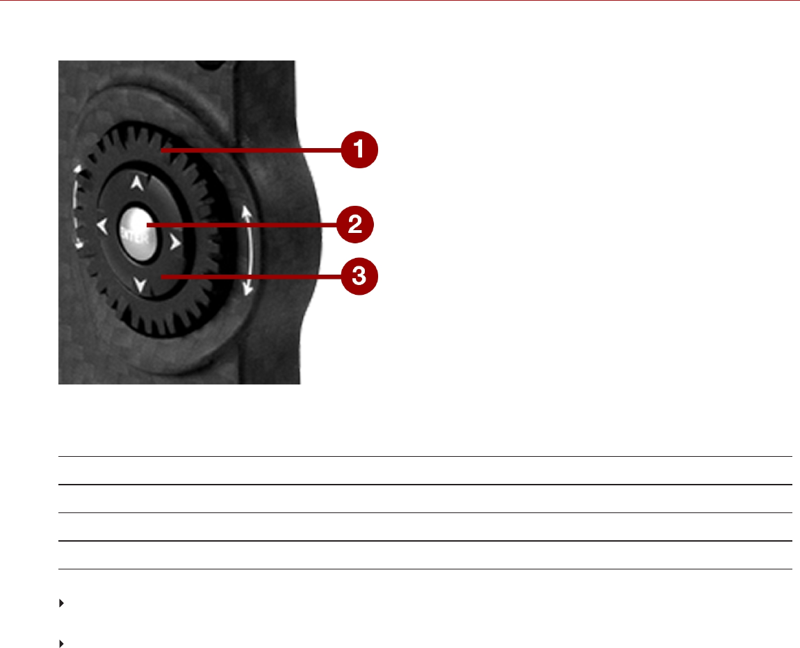
NAVIGATION GROUP
Figure: Navigation Group (DSMC2 SIDEKICK™ Pictured)
The Navigation Group is the primary control interface on the DSMC2 SIDEKICK and DSMC2 Side Handle.
# NAVIGATION GROUP ELEMENT DESCRIPTION
1 Scroll Wheel Select and adjust the value of a selected setting
2 ENTER key Press ENTER to confirm a setting or access the selected menu
3 Directional Keys Navigate menus and menu items
Navigate the menus using the following controls:
Press ENTER to open the menu, then rotate the Scroll Wheel clockwise to move right, counterclockwise to move
left to highlight the desired menu or parameter. Press ENTER to select.
Press the Up Directional Key to open the related Advanced Settings menu, if one (1) is available.
C OPYR I GHT © 2 01 9 R ED. C OM , LLC 955- 0159_V 7. 1, R EV -G | 75
EPIC-W GEMINI OPERATION GUIDE
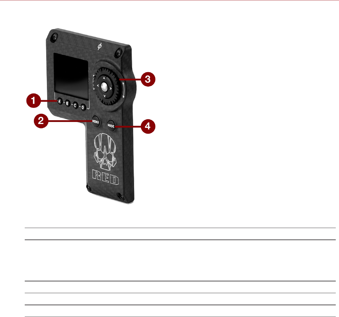
DSMC2 SIDEKICK
Figure: DSMC2 SIDEKICK
# CONTROL/ITEM DESCRIPTION
1 User Keys (A–D)1A: Cycle Auto-Focus Mode
B: Auto White Balance
C: Toggle: Magnify
D: Toggle Exposure Mode
2 MENU Button Access menus or exit currently selected menu
3 Navigation Group Navigate menus and menu items; Go to "Navigation Group" on the previous page
4 MODE Button Toggle between Remote and Local Modes
1. Press User Keys A + D simultaneously to lock/unlock DSMC2 SIDEKICK buttons to prevent inadvertent menu changes.
NOTE: DSMC2 SIDEKICK keys are programmable. For more information, go to "Key Mapping" on page142.
C OPYR I GHT © 2 01 9 R ED. C OM , LLC 955- 0159_V 7. 1, R EV -G | 76
EPIC-W GEMINI OPERATION GUIDE

OPERATION MODES
The DSMC2 SIDEKICK display reflects the currently selected mode. Use the Scroll Wheel and Directional Keys to
navigate menus. Press MENU to access the Advanced Menu.
Press MODE to toggle between the following modes:
Remote Mode: Navigate with DSMC2 SIDEKICK controls, using an attached LCD, EVF, or other monitor as a
reference. The DSMC2 SIDEKICK displays the primary control screen.
Local Mode: Navigate using the DSMC2 SIDEKICK controls and display. User Keys A-D are inactive.
KEY LOCK/UNLOCK
Lock the keys on the DSMC2 SIDEKICK to prevent inadvertent button presses and menu changes.
Lock: Press A + D simultaneously.
Unlock: Press A + D simultaneously. Alternatively, press and hold ENTER while keys are locked.
C OPYR I GHT © 2 01 9 R ED. C OM , LLC 955- 0159_V 7. 1, R EV -G | 77
EPIC-W GEMINI OPERATION GUIDE
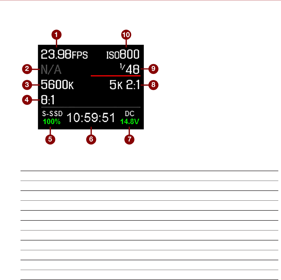
DSMC2 SIDEKICK DISPLAY
The DSMC2 SIDEKICK OLED display provides basic camera parameters during operation.
Figure: DSMC2 SIDEKICK OLED (Local Mode)
The DSMC2 SIDEKICK displays the following camera parameters:
# ITEM DESCRIPTION
1 Frame Rate Current Recording Frame Rate
2 Lens Information Displays aperture if a supported Canon, Nikon, or Cooke lens is attached
3 White Balance Color temperature
4 REDCODE REDCODE compression setting
5 Media Status Displays media location and remaining media capacity
6 Timecode Current timecode value
7 Power Status DC supply voltage or % of remaining battery capacity
8 Resolution Recording resolution
9 Shutter Speed Integration time or shutter angle
10 ISO Camera sensor sensitivity
C OPYR I GHT © 2 01 9 R ED. C OM , LLC 955- 0159_V 7. 1, R EV -G | 78
EPIC-W GEMINI OPERATION GUIDE
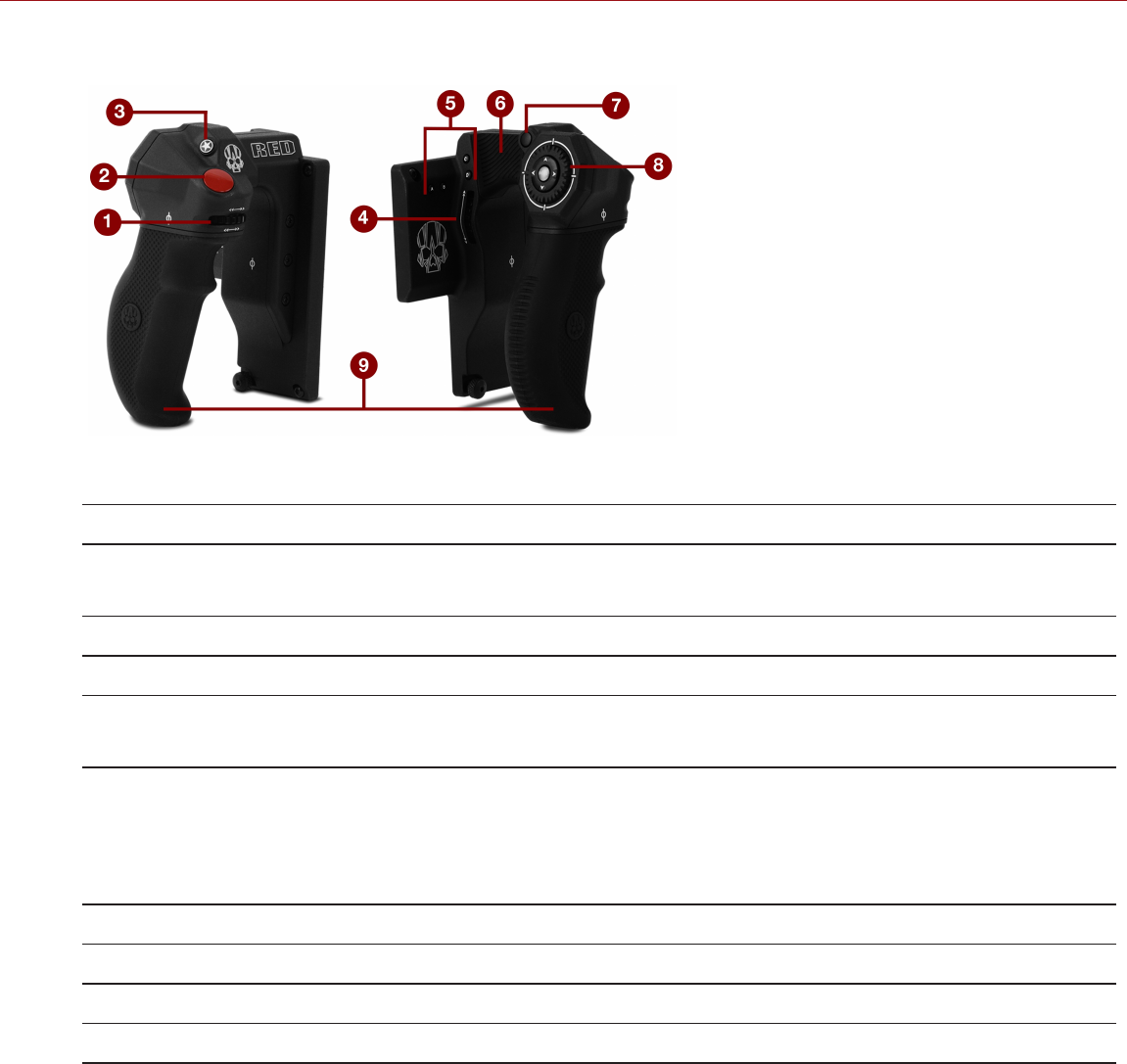
DSMC2 SIDE HANDLE
Figure: DSMC2 Side Handle
# CONTROL/ITEM DESCRIPTION
1 Focus Control Wheel1Clockwise (Away from camera): Increase focus distance
Counter-Clockwise (Toward camera): Decrease focus distance
2 Focus/Record Button Half-press for auto-focus; full press to Start/Stop Record
3 User Key 1 (Mark Frame Button) Mark a frame so that you can easily return to it in playback
4 Rotary Side (Iris Control Wheel)2Clockwise (Up): Open Iris
Counter-Clockwise (Down): Close Iris
5 User Keys (A–D) A: Cycle Auto-Focus Mode
B: Auto White Balance
C: Toggle: Magnify
D: Toggle Exposure Mode
6 Thumb Pad Resting area for thumb
7 MENU Button Access menus or exit currently selected menu
8 Navigation Group Navigate menus and menu items; Go to "Navigation Group" on page75
9 Grip Ergonomic molded rubber grip
1. The Focus Control Wheel is NOT programmable; it cannot be mapped to another function. However, it can be disabled. For more information,
go to "Options" on page142.
2. For granular iris control, you can map keys to Iris: Close (Fine Control) and Iris: Open (Fine Control). The Fine Controls open/close the iris in
increments of 0.1 F stops.
NOTE: Some DSMC2 Side Handle keys are programmable. For more information, go to "Default Key Functions" on
page264.
C OPYR I GHT © 2 01 9 R ED. C OM , LLC 955- 0159_V 7. 1, R EV -G | 79
EPIC-W GEMINI OPERATION GUIDE

FOCUS CONTROL WHEEL
The Focus Control Wheel allows you to physically control the focus length directly from the DSMC2 Side Handle. The
wheel features 270° rotation, and each physical location on the wheel maps directly to a specific focus length of the
lens. The far left point (turning counter-clockwise) maps to the shortest focus distance of the lens, while the far right
point (turning clockwise) maps to the farthest focus distance of the lens (or infinity).
When a DSMC2 Side Handle is attached, you can continue to adjust focus via the Lens menu Menu > Settings >
Setup > Lens, if preferred.
To control focus via the Focus Control Wheel, follow the instructions below:
1. Install a DSMC Nikon Mount or DSMC Canon Mount with a supported lens. For more information on supported
lenses, go to "Lenses" on page252.
2. Set the lens to Auto.
3. Turn on the camera (if it is not already turned on).
The lens initializes and the camera maps each point on the Focus Control Wheel to a focal length of the lens.
4. Control the focal length by moving the Focus Control Wheel:
Clockwise (Away from camera): Increase focus distance
Counter-Clockwise (Toward camera): Decrease focus distance
5. To re-initialize the lens (remap the Focus Control Wheel to the lens focal lengths), go to Menu > Settings > Setup
> Lens and select Lens Init.
C OPYR I GHT © 2 01 9 R ED. C OM , LLC 955- 0159_V 7. 1, R EV -G | 80
EPIC-W GEMINI OPERATION GUIDE
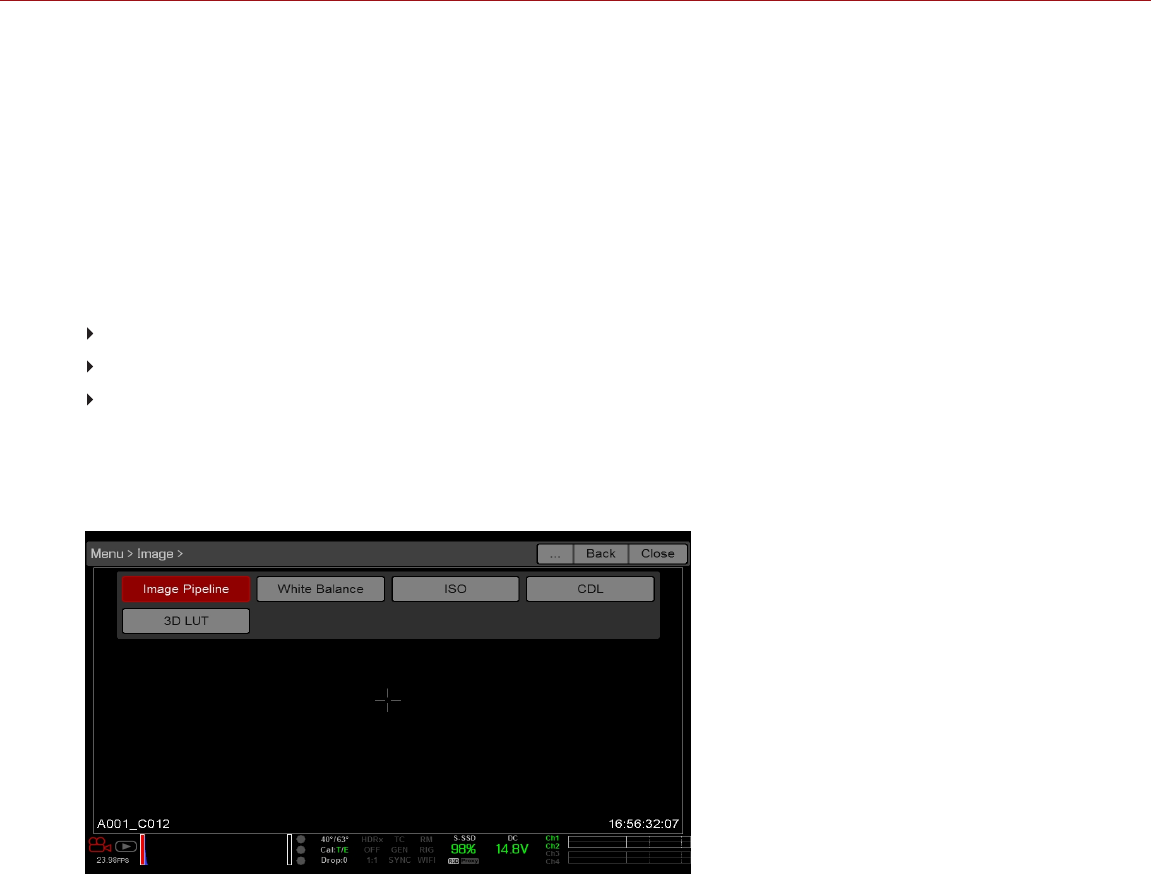
C OPYR I GHT © 2 01 9 R ED. C OM , LLC 955- 0159_V 7. 1, R EV -G |81
EPIC-W GEMINI OPERATION GUIDE
CHAPTER 5:
ADVANCED MENUS
ACCESS THE ADVANCED MENUS
To access the Advanced menus, perform one of the following:
Tap the Menu button on the DSMC2® SIDEKICK™.
Tap the Menu icon on the touchscreen.
Open any menu in the Upper Status Row, and then select the Advanced... button.
NOTE: Some menus are only available if certain hardware is present.
IMAGE MENU
Figure: Image Menu
The Image menu includes tools that control how the image appears, including Color Space and Gamma Curve.
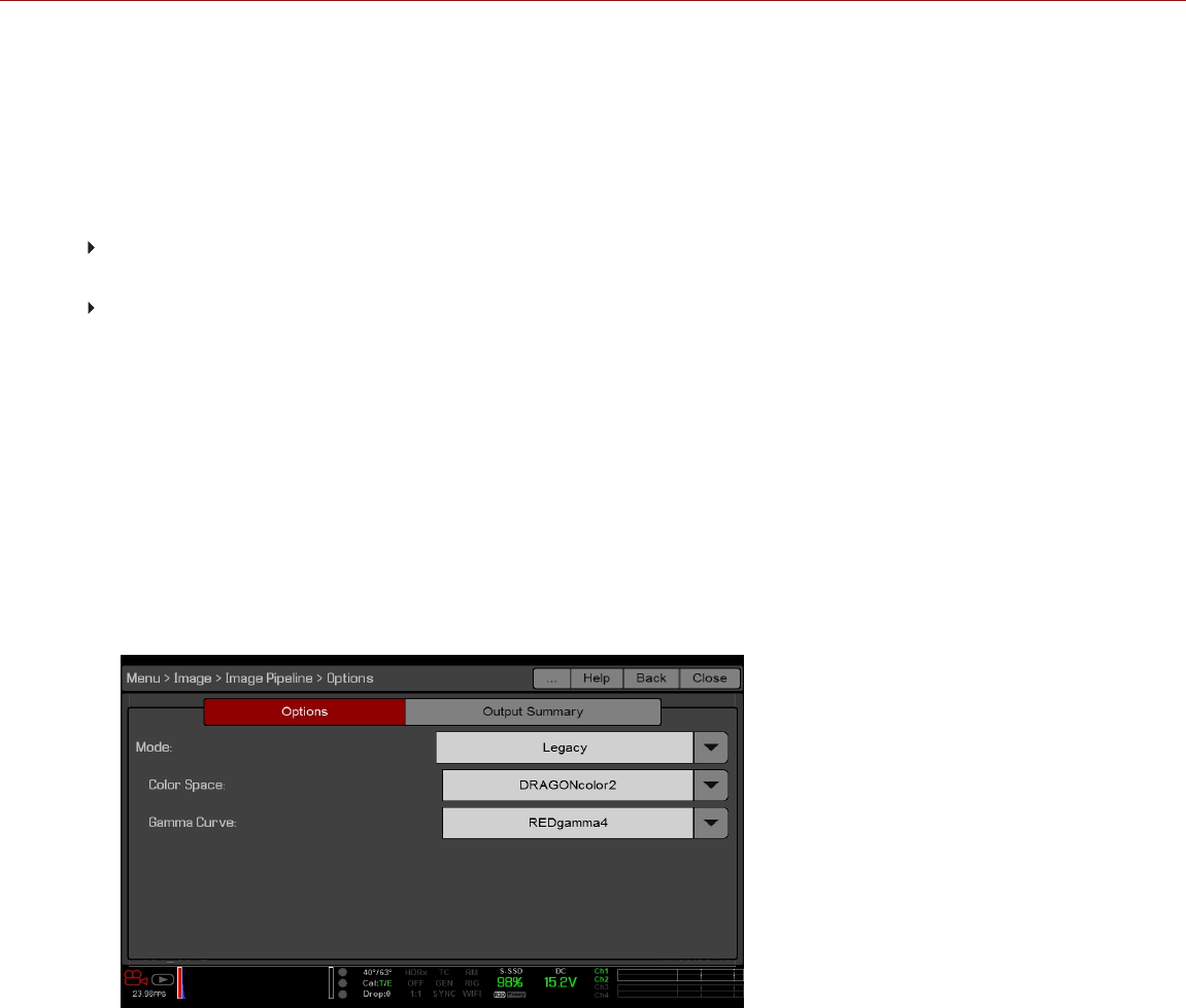
IMAGE PIPELINE
To set up the image pipeline, go to Menu > Image > Image Pipeline.
IMAGE PIPELINE MODE OPTIONS
The camera offers two (2) different ways to process your image. Each mode changes which sub-menus are available in
the Image menu.
Legacy: In Legacy mode, the camera provides the same color options that firmware v6.3 did. Enables the Color,
Gain, Curves, and LGG menus.
IPP2: Image Processing Pipeline 2 (IPP2) is the new image processing pipeline, which is available starting with
firmware v6.4. In IPP2, the camera applies REDWideGamutRGB, which is a color space designed to encompass all
colors a RED camera can generate without clipping. The camera then encodes the image using Log3G10, a gamma
curve that prevents clipping. Using this color space and gamma curve allows you to grade and make color
adjustments in post production, instead of in-camera. Selecting IPP2 enables the CDL menu, and hides the Color,
Gain, Curves, and LGG menus (since those are used for grading).
LEGACY MODE
To use Legacy mode, follow the instructions below:
1. Go to Menu > Image > Image Pipeline > Options.
2. Select Legacy from the Mode drop-down menu.
3. Select OK.
Figure: Legacy Mode
4. Select a color space from the Color Space drop-down menu.
5. Select a gamma curve from the Gamma Curve drop-down menu.
6. If you want to apply a 3D LUT, go to "3D LUT" on page89.
C OPYR I GHT © 2 01 9 R ED. C OM , LLC 955- 0159_V 7. 1, R EV -G | 82
EPIC-W GEMINI OPERATION GUIDE
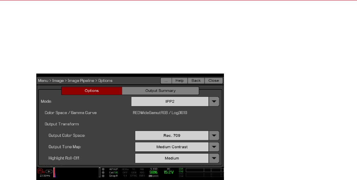
IPP2 MODE
To use IPP2 mode, follow the instructions below:
1. Go to Menu > Image > Image Pipeline > Options.
2. Select IPP2 from the Mode drop-down menu. With IPP2, the Color Space and Gamma Curve are always
REDWideGamutRGB and Log3G10, respectively.
3. Select OK.
Figure: IPP2 Mode
4. If you want to apply a 3D LUT, go to "3D LUT" on page89.
5. Select a color space from the Output Color Space drop-down menu.
6. Select a contrast setting from the Output Tone Map drop-down menu.
7. Select a highlight option from the Highlight Roll-Off drop-down menu.
C OPYR I GHT © 2 01 9 R ED. C OM , LLC 955- 0159_V 7. 1, R EV -G | 83
EPIC-W GEMINI OPERATION GUIDE
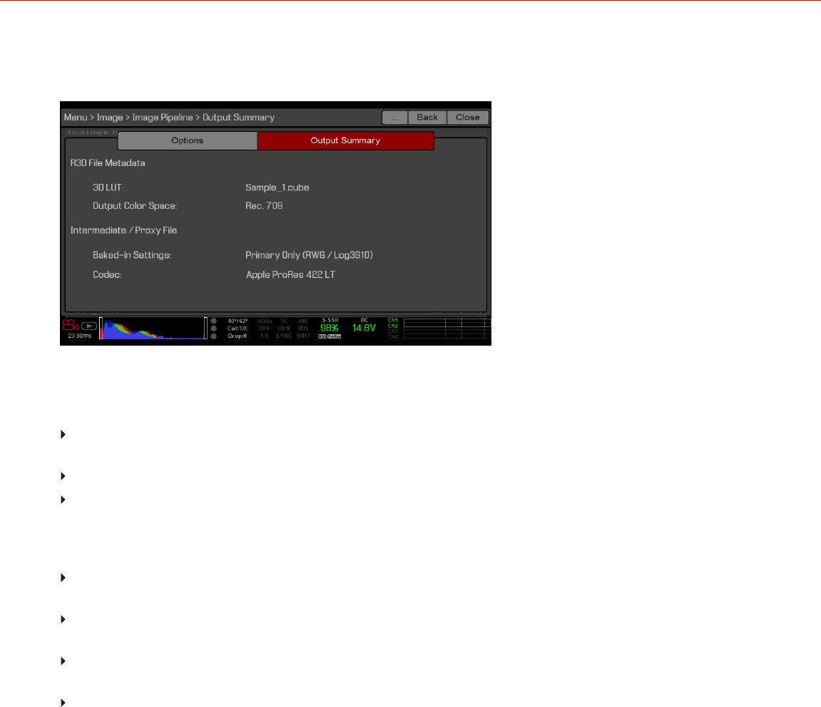
OUTPUT SUMMARY
The Output Summary menu is an information-only menu that displays what image information is applied to the R3D
files and proxy files. To view the output summary, go to Menu > Image > Image Pipeline > Output Summary.
Figure: Image Menu
R3D FILE METADATA
N/A : Displays if the camera is not set to record R3D files. To enable/disable recording to R3D, go to "Select
Record File Format" on page133.
3D LUT: The name of the 3D LUT applied to the file. If no LUT is applied, the screen displays [NONE].
Output Color Space: Applicable to IPP2 mode only. The name of the output color space selected on the Options
tab.
INTERMEDIATE / PROXY FILE
N/A: Displays if the camera is not set to record Apple® ProRes files or Avid DNxHD/HR files. To enable/disable
recording to these files, go to "Select Record File Format" on page133.
Color Space / Gamma Curve: Applicable to Legacy mode only. The color space and gamma curve applied to the
file.
Baked-in Settings: Applicable to IPP2 mode only. The image settings that are irreversibly encoded (baked) into
the recorded file. To select these settings, go to "Select Record File Format" on page133.
Codec: The selected codec. To select a codec, go to "Select Record File Format" on page133.
C OPYR I GHT © 2 01 9 R ED. C OM , LLC 955- 0159_V 7. 1, R EV -G | 84
EPIC-W GEMINI OPERATION GUIDE

WHITE BALANCE
Select a color temperature. The range is 1700 to 10,000 KELVIN, and the default is 5600 KELVIN.
TINT
Color temperature calculations assume a pure light source that may not be true in the specific scene the camera is
imaging. To compensate for any residual colorcast, the Tint parameter adjusts the RGB color balance with a
compensating magenta-green color component. Tint range is –100 to 100, with a default of 0.000.
The Tint value displays as a rounded number in the Upper Status Row.
NOTE: Selecting Auto White Balance calculates a new Tint value. The value does not change if you adjust the color
temperature manually. Selecting a preset resets the Tint to 0.000.
PRESETS
Each preset has 0.000 Tint. Available preset options are:
Incandescent: 2800 K
Tungsten: 3200 K
Fluorescent: 4500 K
Flash: 5500 K
Daylight: 5600 K
Cloudy: 7500 K
Shade: 9000 K
AUTO WHITE BALANCE
Auto white balance analyzes the central 25% of the image visible in the monitor to calculate a color temperature that
will render a white object as white.
To use auto white balance, follow the instructions below:
1. Place a white or grey object under the ambient light.
2. Go to Menu > Image > White Balance.
3. Select Auto White Balance.
C OPYR I GHT © 2 01 9 R ED. C OM , LLC 955- 0159_V 7. 1, R EV -G | 85
EPIC-W GEMINI OPERATION GUIDE
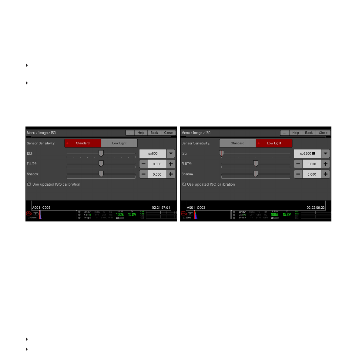
ISO MENU
To select an ISO setting, go to Menu > Image > ISO.
SENSOR SENSITIVITY
Select a Sensor Sensitivity:
Standard: Use in normal shooting conditions in which you would expose near ISO 800. Provides the best highlight
retention.
Low Light: Use in lower light conditions in which you would expose for ISO 2500 and higher. Provides the
cleanest shadow detail. When Low Light is selected, the LL symbol appears next to the ISO rating on both the ISO
menu and in the Upper Status Row. For more information, go to "Upper Status Row (Basic Menu)" on page59.
When you switch between Standard and Low Light, the camera applies the correct sensor calibration for the sensor
sensitivity. For more information, go to "Sensor Calibration" on page159.
Figure: ISO Options for Standard (left) and Low Light (right)
ISO
NOTE: To see the full range of ISO ratings, select ISO in the Upper Status Row, select Edit List, and select Custom.
Select the camera ISO rating. The sensitivity value increments in 1/3 stops. When the ISO rating is adjusted, the
camera logs the change as metadata and the monitor path reacts accordingly. Higher ISO values lead to brighter
images in the monitor path, and vice versa.
RED recommends setting the ISO to the default, then adjusting the aperture, lighting, and ND filters to match. The ISO
can later be adjusted around one (1) stop for fine-tuning.
The camera shows a different default ISO range based on the Sensor Sensitivity option. You can expand this list by
opening ISO from the Upper Status Row and selecting Edit List. For more information, go to "Feature: Edit List" on
page61.
Standard: ISO 250 to 1,600. Default is ISO 800.
Low Light: ISO 1,600 to 12,800. Default is ISO 3,200.
C OPYR I GHT © 2 01 9 R ED. C OM , LLC 955- 0159_V 7. 1, R EV -G | 86
EPIC-W GEMINI OPERATION GUIDE
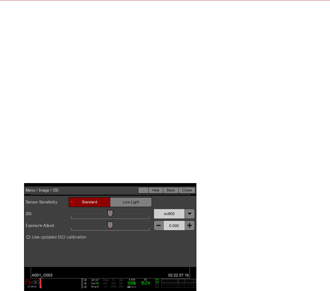
FLUT
NOTE: This feature is only available in Legacy mode. For more information, go to "Image Pipeline" on page82.
Floating Point Lookup Table (FLUT) is an exposure control exclusive to RED. FLUT works like a traditional ISO
setting, but can be fine-tuned in post production to any level of exposure precision. FLUT automatically protects
highlights and shadows, even when changed substantially.
The FLUT setting is expressed in terms of relative exposure value (EV), where each unit represents a 1-stop change in
midtone exposure level. Range is –8.0 to 8.0. Default is 0.0.
SHADOW
NOTE: This feature is only available in Legacy mode. For more information, go to "Image Pipeline" on page82.
Shadow adjusts the toe value of the FLUT (the tone near black). Increasing the Shadow value raises the video level of
near blacks. Lowering the Shadow value crushes the video level of near blacks. Range is –2.0 to 2.0. Default is 0.0.
EXPOSURE ADJUST
NOTE: This feature is only available in IPP2 mode. For more information, go to "Image Pipeline" on page82.
Exposure Adjust (called FLUT in firmware v6.3 and earlier) works like a traditional ISO setting, but can be fine-tuned in
post production to any level of exposure precision. Exposure Adjust automatically protects highlights and shadows,
even when changed substantially.
The Exposure Adjust setting is expressed in terms of relative exposure value (EV), where each unit represents a 1-stop
change in midtone exposure level. Range is –8.0 to 8.0. Default is 0.0.
Figure: Exposure Adjust (Available in IPP2 Mode)
C OPYR I GHT © 2 01 9 R ED. C OM , LLC 955- 0159_V 7. 1, R EV -G | 87
EPIC-W GEMINI OPERATION GUIDE

ISO CALIBRATION
RED cameras with HELIUM®, MONSTRO®, and GEMINI® sensors have an ISO calibration that better matches a light
meter and improves overall exposure quality. RED cameras with HELIUM, MONSTRO, and GEMINI sensors therefore
depict a one stop brighter image compared to prior sensors (when set to an otherwise identical ISO, T-stop, and
shutter speed). ISO 400 now appears as bright as ISO 800 did before, for example.
To match exposure between cameras with HELIUM, MONSTRO, and GEMINI sensors and RED cameras that DO NOT
have those sensors, either reduce your camera’s ISO speed by 1 stop compared to the other camera, or deselect the
Menu > Image > ISO > Use updated ISO calibration check box.
As usual, RED recommends using ISO 800 as a starting point for exposure, then adjusting the T-stop and lighting or
ND filters to match.
CDL
NOTE: This menu is only available in IPP2 mode. For more information, go to "Image Pipeline" on page82.
American Society of Cinematographers Color Decision List (ASC CDL) controls are a standardized, camera-agnostic
way to adjust the look of your images. Color corrections made with a device can therefore be applied or modified by
other devices, even if such devices are from different manufacturers and use different standards.
Use the CDL menu to set up:
Slope
Power
Offset
Saturation
MANAGE CDLS
Use the CDLs menu to apply and import/export CDLs.
CDLs can be stored on the camera or transferred to SSD to be shared with other cameras. When exporting CDLs from
camera to an SSD, the CDLs are saved to a folder on the SSD called “cdls”. When importing CDLs from an SSD to
camera, the CDLs must be stored on the SSD in a folder called “cdls”.
Apply: Apply the selected CDL.
Create: Create a new CDL using the current settings.
Delete: Delete the selected CDL.
: Export selected CDL from camera to SSD.
All: Export all CDLs from camera to SSD.
: Import selected CDL from SSD to camera.
All: Import all CDLs from SSD to camera.
COLOR
NOTE: This menu is only available in Legacy mode. For more information, go to "Image Pipeline" on page82.
Saturation: Adjusts color saturation. Range is 0.0 (monochrome) to 4.0 (super color). Default is 1.0.
Contrast: Adjusts the overall contrast of the image. Range is –1.0 (flat) to 1.0 (max contrast). Default is 0.0.
Brightness: Adjusts brightness without crushing highlights. Available range is –10.0 to 10.0. Default is 0.0.
Exp Comp: Adjusts exposure compensation. Available range is –7.0 to 7.0. Default is 0.0.
C OPYR I GHT © 2 01 9 R ED. C OM , LLC 955- 0159_V 7. 1, R EV -G | 88
EPIC-W GEMINI OPERATION GUIDE

GAIN
NOTE: This menu is only available in Legacy mode. For more information, go to "Image Pipeline" on page82.
Adjust the red channel, blue channel, and green channel individually. The range for each is 0.0 (none of the color) to
10.0, and the default for each is 1.0.
CURVES
NOTE: This menu is only available in Legacy mode. For more information, go to "Image Pipeline" on page82.
Define the individual curves for the luma, red, green, and blue channels. You can only adjust one (1) curve at a time.
Select Reset Curve to reset a curve.
LGG (LIFT, GAMMA, GAIN)
NOTE: This menu is only available in Legacy mode. For more information, go to "Image Pipeline" on page82.
Adjust the lift, gamma, and gain for the red channel, blue channel, and green channel individually.
3D LUT
Use the 3D LUT menu to apply and manage LUTs.
SELECT LUT
If you are recording to a 2K Apple ProRes or 2K Avid DNxHD/HR codec while the camera is in IPP2 mode, you can
chose to irreversibly encode (bake) the 3D LUT into the recorded file. For more information, go to "Select Record File
Format" on page133.
When you apply a 3D LUT to a monitor, the name of the 3D LUT displays in the lower left corner of the Live Action
area for that monitor. The Display Preset feature controls which Color Space / Gamma Curve pairing and/or 3D LUT is
applied to the monitor. For more information, go to "Display Preset" on page91.
NOTE: The 3D LUT indicator is part of the default "Standard (RED)" overlay, which you can override by selecting or
creating a different overlay. For more information, go to "Custom Overlays" on page103.
To apply a 3D LUT, follow the instructions below:
1. Go to Menu > Image > 3D LUT.
2. Select a LUT from the Creative 3D LUT drop-down menu.
3. Select OK.
EXPORT/IMPORT LUTS
To export and import 3D LUTs, go to Menu > Image > 3DLUT > Import/Export.
3D LUTs can be stored on the camera or transferred to SSD to be shared with other cameras. When exporting 3D
LUTs from camera to an SSD, the 3D LUTs are saved to a folder on the SSD called “luts”. When importing 3D LUTs
from an SSD to camera, the 3D LUTs must be stored on the SSD in a folder called “luts”.
: Export selected 3D LUT from camera to SSD.
All: Export all 3D LUTs from camera to SSD.
: Import selected 3D LUT from SSD to camera.
All: Import all 3D LUTs from SSD to camera.
C OPYR I GHT © 2 01 9 R ED. C OM , LLC 955- 0159_V 7. 1, R EV -G | 89
EPIC-W GEMINI OPERATION GUIDE

MONITORING MENU
The Monitoring menu includes tools that control different monitor outputs, Look Around, and overlays.
MONITORS
To set up monitor preferences, go to Menu > Monitoring > Monitors and select the monitor whose preferences you
want to change. You can set up preferences for each of the following monitors:
LCD Top
EVF Top
LCD Left
EVF Left
HDMI® (only available when an HDMI port is connected to the system)
HD-SDI (only available when an HD-SDI port is connected to the system)
MON-1 (only available with the DSMC2 Production Module)
SDI-1/2 (only available with the DSMC2 REDVOLT Expander and DSMC2 Production Module)
To see what monitor preferences are available, go to "Monitor Preferences" below.
MONITOR PREFERENCES
Set up the preferences for the selected monitor. Some options are only available with specific monitors.
NOTE: While some changes take effect immediately, others take effect when you close the menu.
LCD/EVF LEFT / HDMI SELECT
NOTE: This setting is available for the LCD Left, EVF Left, and HDMI.
NOTE: HDMI ports are only available on select DSMC2 expanders. For more information, go to to "Input/Output
Connectors" on page219.
Select to enable either the secondary LCD/EVF port on the camera or the HDMI port on an expander. The secondary
LCD/EVF port and the HDMI port cannot be used at the same time.
LCD/EVF LEFT / MON-1 SELECT
NOTE: This setting is available for LCD Left, EVF Left, and MON-1 when a DSMC2 Production Module is attached.
Select to enable either the secondary LCD/EVF port on the camera or the MON-1 port on the DSMC2 Production
Module. The secondary LCD/EVF port and the MON-1 port cannot be used at the same time.
C OPYR I GHT © 2 01 9 R ED. C OM , LLC 955- 0159_V 7. 1, R EV -G | 90
EPIC-W GEMINI OPERATION GUIDE

MONITOR MODE
Select an option for the Mode setting, which determines the elements displayed on the monitor:
Clean: Only the video displays. The Upper Status Row, Lower Status Row, and overlays do not display.
Overlay: The overlay displays. Overlays include the Upper Status Row and the Lower Status Row.
Mirror: The monitor mirrors another screen at the same resolution. You cannot mirror a screen that is set to Clean.
The Mirror option is available based on the settings of the other attached monitors, and includes the name of the
monitor that can be mirrored.
NOTE: You can set a maximum of four (4) monitors to Overlay at a time. To assign additional monitors to Overlay,
mirror a monitor with the same resolution that is set to Overlay.
NOTE: When two (2) touchscreens are attached to the camera with the same resolution and one (1) is currently the
control surface, set the other to mirror it and give the effect of having two (2) control surfaces.
OVERLAY
Select which overlay shows on top of the video. RED® provides preset overlays, which have “(RED)” in the overlay
name. Create custom overlays in the Overlay tab. For more information, go to "Custom Overlays" on page103.
RESOLUTION
Select the output resolution for monitors (you cannot select a resolution for LCDs and EVFs, since the resolution is
determined automatically). For more information about available HD-SDI and HDMI resolutions, go to "Record/Monitor
Out Ports" on page227.
FREQUENCY
Determines the monitor frequency. Available frequencies depend on the selected monitor. The LCD resolution defaults
to 60.00 Hz, which is the optimal refresh rate for the RED LCDs.
For HD-SDI monitors, the frequency depends on the project time base. For more information, go "Record/Monitor Out
Ports" on page227.
HD-SDI Auto: Sets the frequency equal to the Project Time Base, except when the Project Time Base is 47.95/48 fps.
When the Project Time Base is 47.95/48 fps, the frequency is half that rate (23.98/24 Hz).
DISPLAY PRESET
Select the Color Space and Gamma Curve combination for the monitor. For more information, go to "Image Pipeline"
on page82.
TOOLS
Enables the false color modes on the monitor. For more information, go to "False Color Modes" on page96.
FLIP VIDEO
NOTE: This setting is NOT available on the DSMC2 RED Touch 4.7" LCD, DSMC2 RED Touch 7.0" LCD, RED Touch
7.0" LCD, RED Pro Touch 7.0" LCD, and DSMC2 Touch 7.0" Ultra-Brite LCD.
Flip footage horizontally, so that it is upside down. This setting only affects the monitor, and does not affect captured
footage.
C OPYR I GHT © 2 01 9 R ED. C OM , LLC 955- 0159_V 7. 1, R EV -G | 91
EPIC-W GEMINI OPERATION GUIDE

FRAMED OVERLAY
The video display is scaled down on the monitor so that the overlay items fit outside of the video area rather than over
it. This setting only affects the monitor, and does not affect captured footage.
AUTO HIDE MENUS
Hides the Upper Status Row and Lower Status Row. When this option is disabled, the video is scaled so that the
menus are not overlaid on the video. When this option is enabled, the video is not scaled. This option creates a
control surface on a monitor without scaling the video. This setting only affects the monitor, and does not affect
captured footage.
To toggle display/hide the menus when Auto Hide Menus is enabled, perform either of the following actions:
Press the Menu button.
Tap the touchscreen.
NOTE: Enabling this option on a non-control surface results in the menus never displaying on that monitor.
FLIP/MIRROR
NOTE: This setting is ONLY available on the DSMC2 RED Touch 4.7" LCD, DSMC2 RED Touch 7.0" LCD, RED Touch
7.0" LCD, RED Pro Touch 7.0" LCD, and DSMC2 Touch 7.0" Ultra-Brite LCD.
Mirror and flip (invert) the graphical user interface (GUI) and footage, effectively rotating the entire displayed image
180°. Use this setting when mounting a monitor or the entire camera rig upside down. This setting only affects the
monitor, and does not affect captured footage.
UI FLIP/MIRROR
NOTE: This setting is NOT available on the DSMC2 RED Touch 4.7" LCD, DSMC2 RED Touch 7.0" LCD, RED Touch
7.0" LCD, RED Pro Touch 7.0" LCD, and DSMC2 Touch 7.0" Ultra-Brite LCD.
Flip the GUI vertically and mirror horizontally (not rotated). Use this setting when mounting a monitor upside down.
This setting only affects the monitor, and does not affect captured footage.
BRIGHTNESS
Control the brightness of each LCD and EVF. Move to the right for a brighter display; move to the left for a dimmer
display.
SIDEKICK LCD BRIGHTNESS
To control the brightness of the DSMC2 SIDEKICK, go to Menu > Monitoring > Monitors > SIDEKICK. Move to the
right for a brighter display; move to the left for a dimmer display.
C OPYR I GHT © 2 01 9 R ED. C OM , LLC 955- 0159_V 7. 1, R EV -G | 92
EPIC-W GEMINI OPERATION GUIDE

PRIORITY
The camera can only have one (1) control monitor for interacting with camera settings. The Priority tab determines the
order in which a monitor becomes the control monitor. If you plan on removing or adding monitors during a shoot, set
up the priority list ahead of time.
For a monitor to become the control monitor, the following must occur:
The monitor must be set to Overlay mode in the Monitor Control menu.
Each monitor that has higher priority on the list must be either detached or not set to Overlay mode.
EXAMPLE
By default, the monitor priority is:
1. LCD
2. EVF
3. HDMI
If you remove an LCD when an EVF is attached, then the EVF becomes the control monitor. If you then remove the
EVF when an HDMI monitor is attached, the HDMI monitor becomes the control monitor. If you then re-attach the LCD,
then the LCD is the control monitor again.
TEST SIGNAL
Use the Test Signal menu to replace the video monitor outputs with one of the following video test patterns:
Chip Chart
SMPTE Bars
Luma
NOTE: Test signals are not recordable; they are provided to help align external HD-SDI and HDMI monitors.
AUDIO TONE
To apply an audio tone, follow the instructions below:
1. Go to Menu > Monitoring > Test Signals.
2. Toggle Tone On/Off.
LOOK AROUND
To enable Look Around, go to Menu > Monitoring > Look Around.
When Look Around is enabled, the Frame Guide and recording area are scaled down on the display so that you can
see what images will enter the recording area.
To assign a Shading overlay to the Look Around area (the area outside of the recording area), go to "Guides" on
page102.
Look Around limits the available frame rates. At high resolutions, the recording area on the display shows the full
sensor area or full sensor height, so there is no extra room for Look Around.
Look Around may affect the recorded file:
R3D: Only the area inside the frame is recorded; the Look Around area is NOT recorded.
Apple ProRes: The full image is recorded, including the Look Around area.
Avid DNxHD/HR: The full image is recorded, including the Look Around area.
C OPYR I GHT © 2 01 9 R ED. C OM , LLC 955- 0159_V 7. 1, R EV -G | 93
EPIC-W GEMINI OPERATION GUIDE

ADVANCED
Provides access to additional monitor settings.
VIDEO
SMALL DIALOGS ON 9" LCD
The dialogs on the RED Touch 9.0" LCD are smaller than the default dialogs.
ALLOW REDUCED JUDDER PREVIEW
Reduced Judder Preview allows the camera to preview images at a refresh rate that is twice the project time base. For
example, if the project time base is 23.98 FPS or 24.00 FPS, enabling Reduced Judder Preview causes the LCD or
EVF to have a refresh rate of 48 Hz (50 Hz).
You cannot use Reduced Judder Preview when:
Varispeed is enabled.
Speed Ramp mode is enabled.
Genlock is enabled.
The shutter angle is 180° or greater.
NOTE: When you disable Reduced Judder Preview mode, the image on the EVF may be disrupted for up to three (3)
seconds.
GLOBAL FLIP/MIRROR
Applies Flip/Mirror to all monitors. For more information, go to "Flip/Mirror" on page92.
DISABLE LCD TEMPERATURE WARNINGS
Disables the “cooling advised” messages for the DSMC2 Touch 7.0" Ultra-Brite LCD. For more information, go to
"Cooling Advised Messages" on page207.
OUTPUT SHARPNESS
Control the sharpness of each monitor output. Move to the left for a sharper image; move to the right for a less sharp
image.
NOTE: The sharpness setting affects the Histogram, RAW Level Bars, RAW Clip Meter, and false color modes. For
more information, go to "Histogram" on page69 and "False Color Modes" on page96.
NOTE: The camera applies the sharpness setting to recorded proxy files.
AUTO FOCUS PEAKING
When Auto Focus Peaking mode is enabled (either Focus or Edge), the camera automatically goes onto Focus
Peaking mode when you manually adjust the focus via the lens.
Off: The camera does not automatically go into Focus Peaking mode.
Focus: The camera automatically goes into Focus Peaking mode when you manually adjust the focus via the lens.
Emphasizes contrast and edges in the image without changing brightness or image content making it easier to
judge focus.
Edge: The camera automatically goes into Focus Peaking mode when you manually adjust the focus via the lens.
Shows the edges/outlines of objects that are in focus.
C OPYR I GHT © 2 01 9 R ED. C OM , LLC 955- 0159_V 7. 1, R EV -G | 94
EPIC-W GEMINI OPERATION GUIDE

TOUCH
Lock Touchscreen: Touchscreen control is locked. To unlock, tap the screen and follow the on-screen
instructions.
Pinch to Magnify: Move two (2) fingers apart or together to toggle Magnify. For more information, go to "Display
Modes: Magnify" on page98.
Double Tap Right to Record: Double-tap the right 25% of the video area on the LCD to toggle record.
Double Tap Left to AF: Double-tap the left 25% of the video area on the LCD to start autofocus when compatible
lenses are used.
GENLOCK OFFSET
NOTE: HD-SDI ports are only available on select DSMC2 expanders. For more information, go to "Input/Output
Connectors" on page219.
Offset the video of the HD-SDI out to align it with the genlock signal:
Negative offset: Advances the video, so the video reaches the switcher earlier than it would otherwise.
Positive offset: Delays the video, so the video reaches the switcher later than it would otherwise.
C OPYR I GHT © 2 01 9 R ED. C OM , LLC 955- 0159_V 7. 1, R EV -G | 95
EPIC-W GEMINI OPERATION GUIDE

OVERLAYS MENU
The Overlays menu includes settings that display on top of the monitor image.
TOOLS
The Tools menu provides access to false color and display modes.
For more information, see the Exposure with RED Cameras: False Color & Zebra Tools article , available at
www.red.com/learn/red-101/exposure-false-color-zebra-tools.
FALSE COLOR MODES
False color modes include:
"False Color Modes: Off" below
"False Color Modes: Exposure" on the next page
"False Color Modes: Video" on the next page
"False Color Modes: Focus" on the next page
"False Color Modes: Edge" on the next page
"False Color Modes: Peaking" on page98
"False Color Modes: Gio Scope" on page98
NOTE: Only monitors with the Tools check box selected in the Monitor Control menu show the false colors. For more
information, go to "Tools" on page91.
NOTE: The sharpness setting affects the false color modes. For more information, go to "Output Sharpness" on
page94.
NOTE: False color modes affect video recorded through HDMI® or HD-SDI to an external recorder if the Tools check
box is selected in the Monitor Control menu. When recording through HDMI or HD-SDI, use false color modes only to
help configure project settings, and then disable the mode before recording.
NOTE: Since the 3D LUT modifes the data displayed for the exposure tools, you cannot use the exposure tools with a
3D LUT.
DISPLAY MODES
Display modes include:
"Display Modes: Magnify" on page98
"Display Modes: Log View" on page99
"Display Modes: RAW" on page99
"Display Modes: Horizon" on page99
"Display Modes: Zebras" on page100
FALSE COLOR MODES: OFF
To disable all false color modes, go to Menu > Overlays > Tools > False Color and select Off from the False Color
drop-down menu.
C OPYR I GHT © 2 01 9 R ED. C OM , LLC 955- 0159_V 7. 1, R EV -G | 96
EPIC-W GEMINI OPERATION GUIDE

FALSE COLOR MODES: EXPOSURE
To enable, go to Menu > Overlays > Tools > False Color and select Exposure from the False Color drop-down
menu.
The Exposure tool displays a color overlay on top of a desaturated image that allows you to check for proper
exposure. When enabled, the “E√” indicator displays in the Lower Status Row.
The Exposure meter colors indicate the following information:
Purple: Underexposed; indicates sensor exposure levels that may be noisy if gained up in post production.
Green: IRE 41–48; based on the RGB levels of the video out signal and not the RAW data.
Red: Overexposed; indicates sensor exposure levels that are clipping.
Purple (underexposure) and red (overexposure) are based on RAW data and show areas that are clipping or close to
clipping. The RGB settings DO NOT affect the Exposure indicators.
FALSE COLOR MODES: VIDEO
To enable, go to Menu > Overlays > Tools > False Color and select Video from the False Color drop-down menu.
The Video tool displays a color overlay that indicates the video level of the RGB monitor path (calibrated to the
SMPTE test signal). When enabled, the “V√” indicator displays in the Lower Status Row.
Colors are based on the RGB levels of the video out signal (that is, the “cooked” look, and not RAW data). The RGB
settings affect the Video indicators.
The Video indicators represent the following IRE values (at all other values, the desaturated image represents the
luminance value of the ISO adjusted image):
Purple: IRE 0–4
Blue: IRE 5
Teal: IRE 10–12
Green: IRE 41–48
Pink: IRE 61–70
Straw: IRE 92–93
Yellow: IRE 94–95
Orange: IRE 96–98
Red: IRE 99–100
FALSE COLOR MODES: FOCUS
To enable, go to Menu > Overlays > Tools > False Color and select Focus from the False Color drop-down menu.
The Focus tool emphasizes contrast and edges in the image without changing brightness or image content making it
easier to judge focus. Adjust zoom and focus to easily see which objects are coming into focus.
When enabled, the “F√” indicator displays in the Lower Status Row.
FALSE COLOR MODES: EDGE
To enable, go to Menu > Overlays > Tools > False Color and select Edge from the False Color drop-down menu.
Shows the edges/outlines of objects that are in focus. When enabled, the “F√” indicator displays in the Lower Status
Row.
NOTE: The Edge setting may interfere with recordings done via HDMI or HD-SDI in Clean mode.
C OPYR I GHT © 2 01 9 R ED. C OM , LLC 955- 0159_V 7. 1, R EV -G | 97
EPIC-W GEMINI OPERATION GUIDE

FALSE COLOR MODES: PEAKING
To enable, go to Menu > Overlays > Tools > False Color and select Peaking from the False Color drop-down
menu.
The Focus Peaking tool displays a red overlay on top of in-focus edges. Select a Peaking Level of 1 to 10 (weak to
strong). The RGB settings affect the indicators.
The Focus Peaking indicators are applied after the image is scaled to a monitor, so the indicators may look different
on different monitors.
When enabled, the “P√” indicator displays in the Lower Status Row.
FALSE COLOR MODES: GIO SCOPE
To enable, go to Menu > Overlays > Tools > False Color and select Gio Scope from the False Color drop-down
menu.
Displays a color overlay on top of a desaturated image, identifying 16 increments within the dynamic range of the
sensor.
When enabled, the “G√” indicator displays in the Lower Status Row. The Gio Scope indicators are based on RAW
data. The RGB settings (color temperature, ISO, LGG, etc.) DO NOT affect the indicators.
Each number indicates a different increment of dynamic range.
10: Represents mid-grey.
16: Represents the top increment, and is broken up into 1/8th sub-increments to show highlight roll-off. Each 1/8th
increment is represented by a different shade of red, ranging from light red (less light) to dark red (most light).
DISPLAY MODES: MAGNIFY
To enable, go to Menu > Overlays > Tools and select Magnify.
The Magnify tool displays the central region of the sensor in 1:1 pixel resolution on an attached monitor. When
enabled, the 1:1 text in the Lower Status Row turns green, and the AF Window and the magnified region display. The
AF Window determines the center point of the magnified region. If the lens or lens mount is not capable of autofocus
with the camera, use Confirm mode to turn on the AF Window. Sharpening is disabled when Magnify mode is
enabled. The camera automatically exits Magnify mode when recording begins.
The Magnify tool magnifies a 1920 x 1020 region, centered on a 1920 x 1080 display. If the resolution is lower than
1920 x 1020, the image border cannot be magnified. Use the following equations to determine the area of the image
border that will not be magnified:
Border width: (1920 – W) / 2
Border height: (1020 – H) / 2
NOTE: Frame rate and resolution cannot be modified in Magnify mode.
C OPYR I GHT © 2 01 9 R ED. C OM , LLC 955- 0159_V 7. 1, R EV -G | 98
EPIC-W GEMINI OPERATION GUIDE

DISPLAY MODES: RAW
NOTE: RAW is only available in Legacy mode. For more information, go to "Image Pipeline" on page82.
To enable, go to Menu > Overlays > Tools and select RAW.
When enabled, the camera displays images unaffected by the RGB settings (color temperature, ISO, LGG, etc.). RAW
affects the video recorded via HDMI or HD-SDI to an external recorder. RAW image parameters DO NOT affect image
metadata; the parameters only affect the monitor output.
The RAW image parameters are:
Color Space: DRAGONcolor2
Gamma Space: REDgamma4
White Balance: 5600K
ISO: 800 ISO
Tint: 0 Tint
NOTE: In RAW mode, the following controls are disabled on all cameras: color temperature, tint, saturation, RGB
gains, ISO, contrast, brightness, shadow, FLUT®, exposure compensation, LGG controls, RGB curves, and luma
curve.
DISPLAY MODES: LOG VIEW
NOTE: Log View is only available in IPP2 mode. For more information, go to "Image Pipeline" on page82.
To enable, go to Menu > Overlays > Tools and select Log View.
When enabled, the camera displays images in REDWideGamutRGB and Log3G10 that are only affected by the ISO,
Exposure Adjust, Color Temperature, and Tint settings. This allows you to quickly see ungraded footage that remains
unaffected by creative decisions such as the choice of 3D LUT or CDL. Log View affects the video recorded via HDMI
or HD-SDI to an external recorder, but does not affect the R3D file itself.
DISPLAY MODES: HORIZON
To enable, go to Menu > Overlays > Tools and select Horizon.
Displays an overlay that provides a reference to the position of the horizon. The Horizon overlay consists of two (2)
short side-bars that are always horizontally centered on the monitor, and a single longer horizon-line that adjusts to the
horizon based on the orientation of the camera.
The side-bars are green if the pitch is within +/– 1° of the calibrated zero position, otherwise they are red. The horizon-
line is green if the roll is within +/– 1° of the calibrated zero position, otherwise it is red.
To add numerical values for the pitch and roll to the Horizon overlay, follow the instructions below:
1. Go to Menu > Overlays > Custom.
2. Select Create..., Clone..., or Edit..., respectively, for the desired overlay action.
3. Select a location on the interface to add the numerical data for the Horizon overlay.
4. Select Motion: Gyro Data (GYRO) from the Item drop-down menu.
5. Select the desired text size.
6. Select Add.
7. Select Save.
8. Apply the custom overlay to a monitor. For more information, go to "Monitor Preferences" on page90.
NOTE: The internal gyroscope and accelerometer must be calibrated for the Horizon overlay to function properly. For
more information, go to "Gyroscope and Accelerometer Calibration" on page154.
C OPYR I GHT © 2 01 9 R ED. C OM , LLC 955- 0159_V 7. 1, R EV -G | 99
EPIC-W GEMINI OPERATION GUIDE

DISPLAY MODES: ZEBRAS
Use Zebra mode to enable and adjust the upper and lower values for two (2) independent zebra indicators. Use Zebra
1 for highlight exposure, and use Zebra 2 for mid-tones or shadows. Zebras are visible in Magnify mode and are
disabled by default.
The camera offers two (2) zebra types:
Video: IRE-based mode; evaluates based on the current ISO and Look settings, and not the RAW image.
RAW: Evaluates based on the RAW image.
For more information, see the Exposure with RED Cameras: False Color & Zebra Tools article , available at
www.red.com/learn/red-101/exposure-false-color-zebra-tools.
ENABLE ZEBRA INDICATORS
1. Go to Menu > Overlays > Tools and select Zebras.
2. Select a Zebra:
Zebra 1:
Video: Areas of the image exposed within the IRE range are indicated by red diagonal lines at –45°. Default
is 98 to 100 IRE.
RAW: Areas of the image exposed within the range of stops are highlighted. Default is 15.80 to 16.00 stops.
Zebra 2:
Video: Areas of the image exposed within the IRE range are indicated by green diagonal lines at 45°. Default
is 41 to 48 IRE.
RAW: Areas of the image exposed within the range of stops are highlighted. Default is 0.00 to 4.00 stops.
3. If you selected RAW, select how you want the RAW areas to look by setting up the Raw Style options (fill and
color).
C OPYR I GHT © 2 01 9 R ED. C OM , LLC 955- 0159_V 7. 1, R EV -G | 100
EPIC-W GEMINI OPERATION GUIDE

CAMERA AND LENS STATUS
To set up what camera and lens info displays as part of the overlay, go to Menu > Overlays > Status.
CAMERA STATUS OVERLAYS
EXPOSURE
Shutter Speed: Displays the exposure time in seconds (1/xx sec). When you change the frame rate in this mode,
the shutter speed stays the same, but the shutter angle changes. (Default)
Shutter Angle: Displays the exposure as an angle (1° to 360°). When you change the frame rate in this mode, the
shutter angle stays the same, but the shutter speed changes.
POWER
Current Batt %: Displays the remaining percentage of active battery. (Default)
Total Time: Displays the total run-time left of battery power, taking into account all available batteries.
Voltage: Displays the voltage.
VU METER
Input: Displays levels of audio inputs (pre-mixer). (Default)
Output: Displays levels of audio outputs (post-mixer).
HISTOGRAM
RGB: Displays red, green, and blue channels on histogram. (Default)
Luma: Displays luma channel on histogram.
MEDIA
Percentage: Displays media space remaining as a percentage. (Default)
Time Remaining: Displays media space remaining as time in hours and minutes (HHH:MM).
LENS STATUS OVERLAYS
APERTURE INCREMENTS
1/4 Stop: Aperture increments in 1/4 stops.
1/3 Stop: Aperture increments in 1/3 stops. (Default)
FOCUS DISTANCE
Metric: Displays lens focus distances in meters.
Imperial: Displays lens focus distances in feet and inches. (Default)
MOTION MOUNT ND AND MOTION MOUNT ISO PULL
Only applicable when using a DSMC RED MOTION MOUNT® S35 lens mount. For more information, see the RED
MOTION MOUNT Operation Guide, available at www.red.com/downloads.
C OPYR I GHT © 2 01 9 R ED. C OM , LLC 955- 0159_V 7. 1, R EV -G | 101
EPIC-W GEMINI OPERATION GUIDE

RACK SHOW DISTANCE
On: Displays the focus distance of each rack point on the Live Action Area when rack focus is enabled. For more
information, go to "Set Up Rack Focus" on page139.
Off: Does not display the focus distance of rack points when rack focus is enabled. (Default)
GUIDES
Use the Guides menu to configure the Frame Guide, Action Guide, and Title Guide.
MODE
Off: Disable all guides.
Full: Guide has the same aspect ratio as the record format.
4:3, 16:9, 1.85:1, 1.9:1, 2.4:1: Guide has the selected aspect ratio.
User: Select an aspect ratio from the drop-down menu that displays when you select this option.
Absolute: Guide is defined by absolute pixel dimensions rather than aspect ratio and scale. When you select
Absolute, the Width/Height fields replace the Scale field.
SCALE
Percentage to scale guide from its maximum possible size. Available range is 0 to 100%.
WIDTH/HEIGHT
The Width/Height fields replace the Scale field when you select Absolute from the Mode drop-down menu. Select the
values for the width and height of the guide in pixels.
OFFSET X/Y
Percentage to offset guide from its default centered position. Available range is –100 to 100%.
100%: Right-aligned (for X offset) and bottom-aligned (for Y offset).
-100%: Left-aligned (for X offset) and top-aligned (for Y offset).
APPEARANCE
Line Style: Select one of the following line styles: Solid, Dashed, or Bracket.
Color: Select the color that has the highest contrast to the scene. The default is White.
Opacity: Set the guide opacity. Available options are 25%, 50%, 75% and 100%.
RELATIVE TO FRAME GUIDE
Select the Relative to Frame Guide check box to size and position the guide relative to (and have it bounded by) the
Frame Guide instead of the record format.
NOTE: The Relative to Frame Guide check box is available on the Action Guide and Title Guide tabs.
Enable/Disable and select the location (Relative To), color, and opacity of the following elements:
Center: The center crosshair. You can select the following shapes: Cross (crosshair), Small Dot, Medium Dot.
Grid: Rule-of-thirds grid.
Shading: The shaded region outside of the area of interest.
C OPYR I GHT © 2 01 9 R ED. C OM , LLC 955- 0159_V 7. 1, R EV -G | 102
EPIC-W GEMINI OPERATION GUIDE

CUSTOM OVERLAYS
Create custom overlays that include specific items. Overlays can be stored on the camera or transferred to SSD to be
shared with other cameras.
Camera: Overlays saved internally on the camera display in the Overlay drop-down menu on the Monitor Control >
Monitor tab.
Media: Overlays saved to an SSD can be found at On Media: \overlays:.
NOTE: Overlays that end with (RED) are provided by default and cannot be edited, deleted, or exported.
OVERLAY ACTIONS
Create...: Create a new custom overlay using a blank overlay template in the Overlay Editor.
Clone...: Create a new custom overlay using the selected camera overlay as a template in the Overlay Editor.
Edit...: Edit the selected camera overlay in the Overlay Editor.
Delete: Delete the selected camera overlay.
EXPORT AND IMPORT OVERLAYS
: Export selected overlay from camera to SSD.
All: Export all overlays from camera to SSD.
: Import selected overlay from SSD to camera.
All: Import all overlays from SSD to camera.
C OPYR I GHT © 2 01 9 R ED. C OM , LLC 955- 0159_V 7. 1, R EV -G | 103
EPIC-W GEMINI OPERATION GUIDE

CREATE AND EDIT OVERLAYS
1. Go to Menu > Overlays > Custom.
2. Select Create, or select an existing overlay and select Clone or Edit.
3. If creating a new overlay, enter a name for the overlay and select OK.
4. Select any of the following check boxes to add the corresponding guides to the overlay:
Frame Guide
Action Guide
Title Guide
5. Select a button on the matrix to add a user interface element to that position on the matrix.
By default, the Magnify indicator (MI) is on the top left, the Record indicator (REC) is on the top right, the Clip
Name (CLIP) is on the bottom left, and the Timecode (TC) is on the bottom right.
Selecting one (1) of the buttons opens a new dialog that lets you choose a user interface element.
6. Select the Item that you want to add.
7. Select the Size of the item.
8. If adding a Custom Label (LBL), enter the Custom Text for that item.
9. Select Add to return to the previous screen.
10. Add all of the items to the overlay.
11. Select Create or Save.
The new overlay displays in the Camera list.
NOTE: Except for the Custom Label (LBL), you can only add each element once. If you add an element you have
already added to the overlay, the element moves to the new position.
C OPYR I GHT © 2 01 9 R ED. C OM , LLC 955- 0159_V 7. 1, R EV -G | 104
EPIC-W GEMINI OPERATION GUIDE
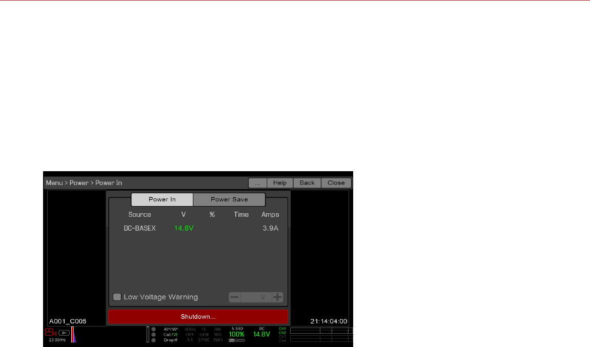
POWER MENU
The Power menu displays the power status of all attached power sources and allows you to turn off the camera.
To access the Power Menu, go to Menu > Power.
NOTE: For more information about powering the camera, see the DSMC Power Operation Guide, available at
www.red.com/downloads.
POWER IN
The power status displays for all attached power devices. The menu displays the voltage of the source or the relative
percentage of the power left, as well as the time left, if applicable.
Figure: Power In Menu
C OPYR I GHT © 2 01 9 R ED. C OM , LLC 955- 0159_V 7. 1, R EV -G | 105
EPIC-W GEMINI OPERATION GUIDE
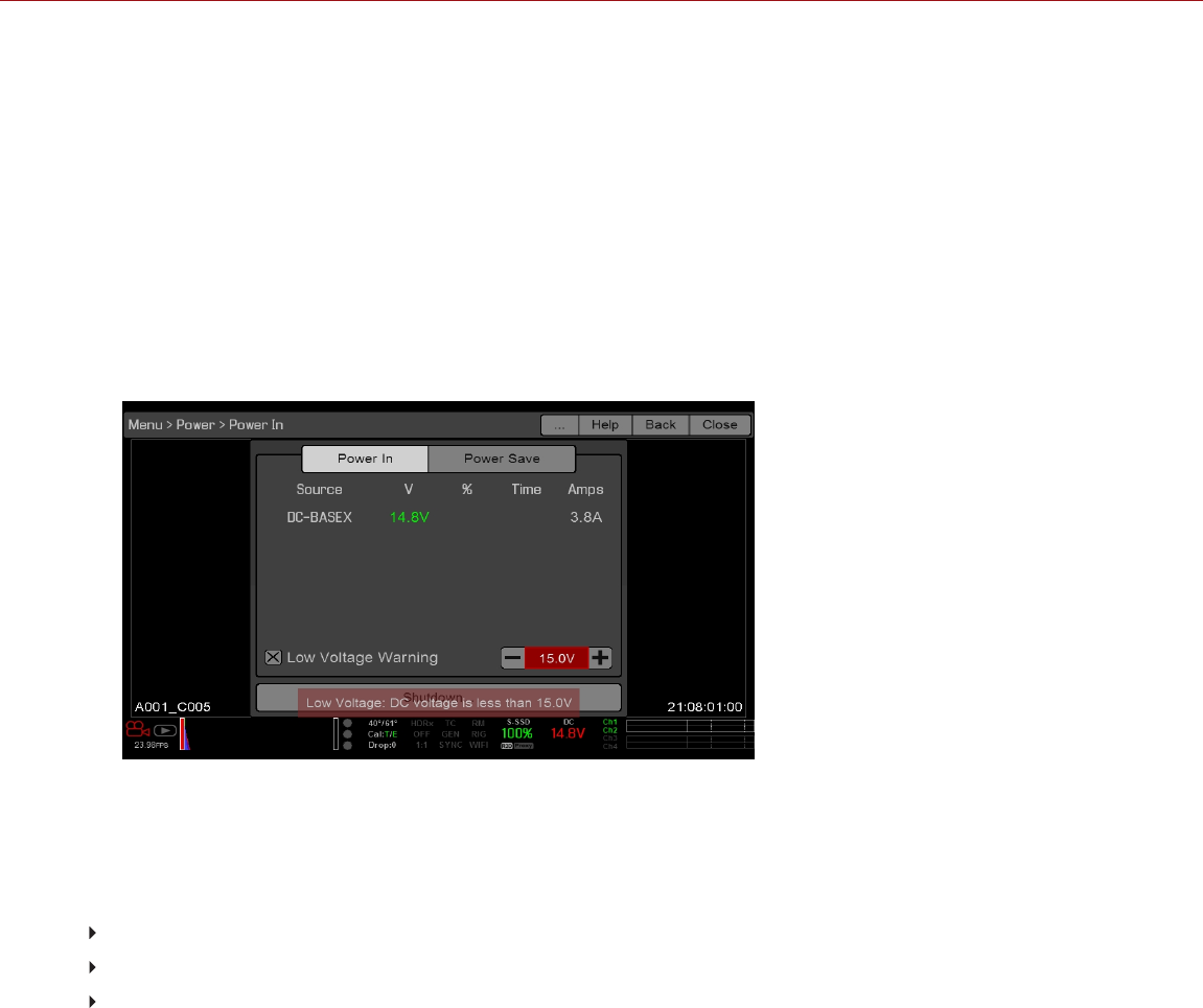
LOW VOLTAGE WARNING
When the Low Voltage Warning is enabled and the incoming voltage is less than the level you select, the camera
shows a warning message and the Power Status indicator in the Lower Status Row turns red. This warning gives you
the opportunity to change the battery or prepare for the camera to lose power. The warning continues to show until the
incoming voltage is equal to or higher than the level you select.
RED does not recommend a specific voltage threshold, since that depends on the power draw of the attached
accessories.
To enable the Low Voltage warning, follow the instructions below:
1. Go to Menu > Power.
2. Select the Low Voltage Warning check box.
3. Select the voltage level threshold. The camera warns you when the incoming voltage is less than this level.
Figure: Low Voltage Warning
POWER OUT
The Power Out menu shows the status of the power out ports on the attached devices. The statuses are:
N/A: The device is not present.
OK: The power out port is functional.
FAULT: A short or overcurrent tripped the electronic fuse. Remove the device that is connected to the port, as it
may be drawing too much power. Select RESET to clear the fault.
When the DSMC2 REDVOLT Expander is attached, you can see the current output of each power out port (in amps),
and toggle those ports on/off.
C OPYR I GHT © 2 01 9 R ED. C OM , LLC 955- 0159_V 7. 1, R EV -G | 106
EPIC-W GEMINI OPERATION GUIDE
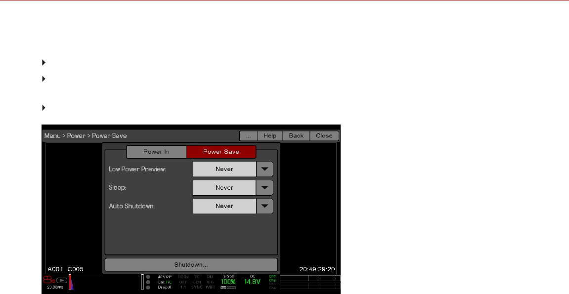
POWER SAVE
You can select the following power saving options (the default for each is Never):
Low Power Preview: The camera uses a lower amount of power after the specified period of inactivity.
Sleep: All monitors turn off and keys do not perform mapped actions after the specified period of inactivity. Tap
the touchscreen or press a key to exit Sleep mode.
Auto Shutdown: The camera turns off after the specified period of inactivity.
Figure: Power Save
SHUTDOWN
Shutdown controls are interlocked to prevent the camera from being accidentally turned off. For more information
about different ways to turn off your camera, go to "Turn Off the Camera" on page45.
1. Go to Menu > Power.
2. Select Shutdown.
The Shutting Down... message displays and the camera turns off.
C OPYR I GHT © 2 01 9 R ED. C OM , LLC 955- 0159_V 7. 1, R EV -G | 107
EPIC-W GEMINI OPERATION GUIDE

PLAYBACK
To view clips from the SSD:
Go to Menu > Playback.
Press the Record/Playback toggle in the lower left corner of the touchscreen.
NOTE: The camera uses RGB color space in Playback mode by default, regardless of settings in Record mode. To
playback clips in RAW mode, enable to RAW mode. For more information, go to "Tools" on page96.
PLAYBACK MENUS
In Playback mode, the menu is pared-down, so you cannot access all menus. Some menus offer different options.
MEDIA
Includes the Playlist menu, which lists all available clips on the attached SSD. You can perform the following actions:
: Move selected clip to the Play List.
All : Move all clips to the Play List.
RECORD (EXIT)
Select Record to exit Playback mode. You can also press any button mapped to Record to exit Playback mode.
PLAYBACK STATUS BAR
Displays the progress of the clip during playback. When using the touchscreen, swipe your finger right and left to fast-
forward and rewind the clip, respectively.
C OPYR I GHT © 2 01 9 R ED. C OM , LLC 955- 0159_V 7. 1, R EV -G | 108
EPIC-W GEMINI OPERATION GUIDE
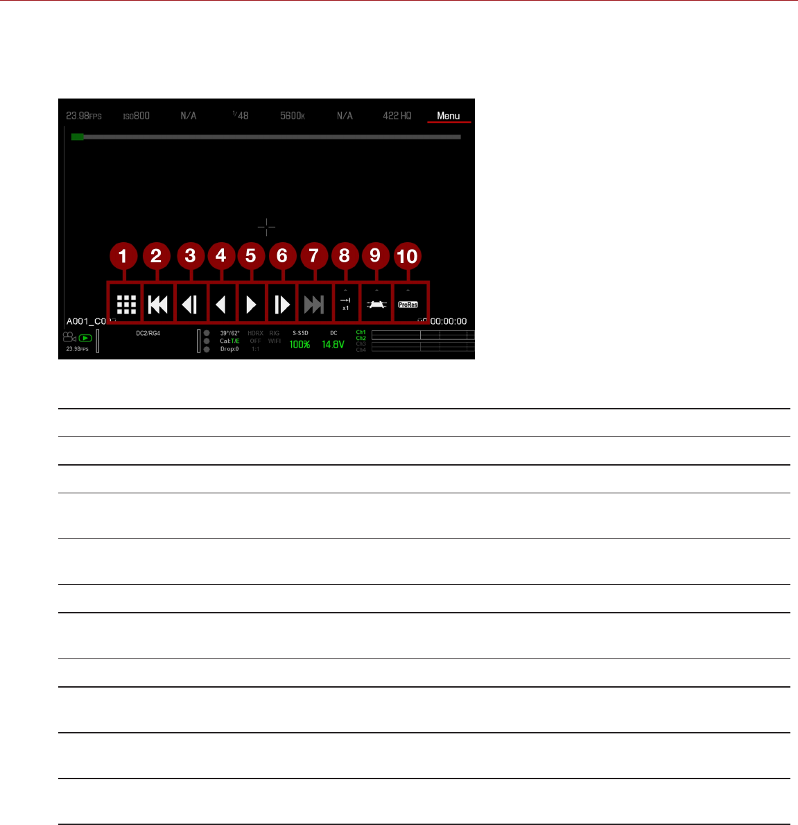
PLAYBACK CONTROLS
GENERAL PLAYBACK CONTROLS
Figure: Playback Controls
# CONTROL DESCRIPTION
1 Clips View clips as thumbnails
2 Load Previous Clip Loads the previous clip in the playlist.
3 Frame-by-Frame
Reverse
Moves through the clip frame-by-frame in reverse.
4 Reverse Play/Pause
toggle
Plays clip in reverse, and toggles between play and pause.
5 Play/Pause toggle Toggles between play and pause.
6 Frame-by-Frame
Forward
Moves through the clip frame-by-frame.
7 Load Next Clip Loads the next clip in the playlist.
8 Play Options Displays the following subset of options: Play Once, Loop, Loop Playlist, and Playback
Speed.
9 Marker Options Displays the following subset of options: In Point, Remove In/Out Point, Out Point,
Previous Marker, and Next Marker.
10 Apple ProRes
Playback
Displays the following subset of options: R3D and ProRes
C OPYR I GHT © 2 01 9 R ED. C OM , LLC 955- 0159_V 7. 1, R EV -G | 109
EPIC-W GEMINI OPERATION GUIDE
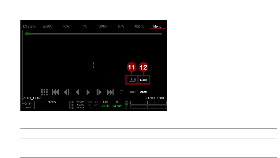
PLAYBACK FILE TYPE
Figure: Playback Controls
# CONTROL DESCRIPTION
11 R3D Playback Plays the R3D clip.
12 ProRes Plays the Apple ProRes clip.
C OPYR I GHT © 2 01 9 R ED. C OM , LLC 955- 0159_V 7. 1, R EV -G | 110
EPIC-W GEMINI OPERATION GUIDE
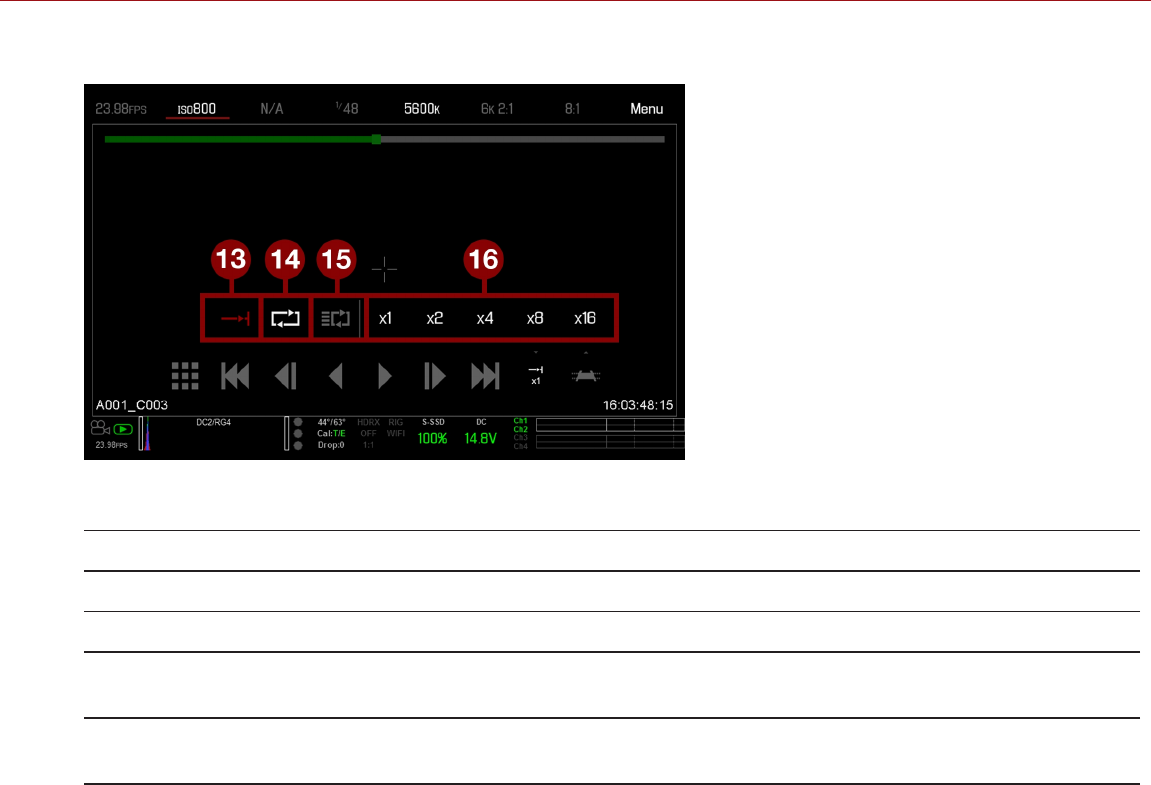
PLAYBACK SPEED AND LOOPING
Figure: Playback Controls
# CONTROL DESCRIPTION
13 Play Once Plays clip to the end, and does not repeat the clip.
14 Loop Plays the clip on a loop.
15 Loop Playlist Loops all clips in the playlist. To create a playlist, go to Menu > Media > Playlist, and move
clips to the Play List field.
16 Playback
Speed
Option to select x1, x2, x4, x8, or x16 playback speed.
C OPYR I GHT © 2 01 9 R ED. C OM , LLC 955- 0159_V 7. 1, R EV -G | 111
EPIC-W GEMINI OPERATION GUIDE
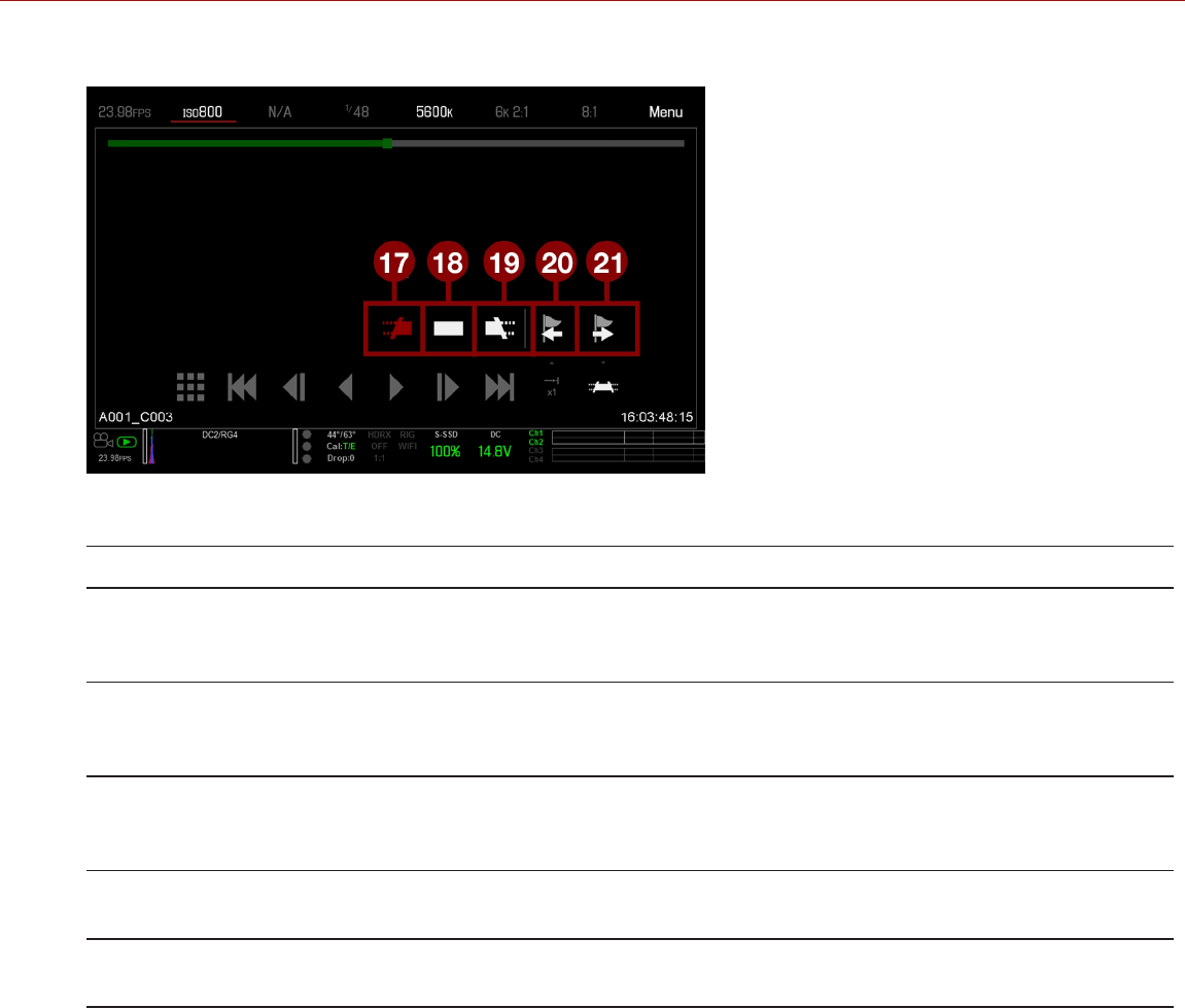
PLAYBACK MARKERS
Figure: Playback Controls
# CONTROL DESCRIPTION
17 In Point Sets a red In Point marker in the Playback Status Bar. Use an In Point marker in conjunction with an
Out Point marker to play only a certain portion of a clip. The In/Out Point markers help when the clip
is long and you want to focus on a particular segment.
18 Remove
In/Out
Point
Removes the In/Out Point markers and skips to the end of the clip.
19 Out Point Sets a red Out Point marker in the Playback Status Bar. Use an Out Point marker in conjunction with
an In Point marker to play only a certain portion of a clip. The In/Out Point markers help when the
clip is long and you want to focus on a particular segment.
20 Previous
Marker
Goes to the previous marked frame, which displays as a red line in the Playback Status Bar.
Disabled when there are no marked frames.
21 Next
Marker
Goes to the next marked frame, which displays as a red line in the Playback Status Bar. Disabled
when there are no marked frames.
C OPYR I GHT © 2 01 9 R ED. C OM , LLC 955- 0159_V 7. 1, R EV -G | 112
EPIC-W GEMINI OPERATION GUIDE
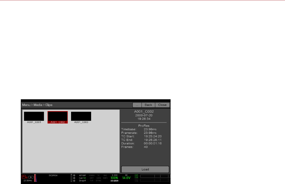
MEDIA MENU
The Media Menu allows you to format and eject an SSD and to view and load clips on the SSD.
For more information about using media, see the DSMC Media Operation Guide , available at
www.red.com/downloads.
DEVICE
Format and eject (unmount) the SSD.
To see information about the SSD in the camera, select More Info....
CLIPS
View and load clips on the SSD in thumbnail view.
Figure: Clips Menu
C OPYR I GHT © 2 01 9 R ED. C OM , LLC 955- 0159_V 7. 1, R EV -G | 113
EPIC-W GEMINI OPERATION GUIDE

PRESETS MENU
The camera has the following presets:
Camera Presets: These store and recall camera setup information, such as in-camera Looks, key mappings, I/O
configurations, and more. The camera has a number of factory-installed presets.
Looks: These allow you to save the specific color, image, white balance, and detail settings to be used for other
projects. Looks that are generated in-camera display on the Camera Presets tab. Looks that are generated in
REDCINE-X PRO and are imported to the camera display on the Looks tab.
Auto Presets: These allow you to specify pre-selected presets for Startup, Preview, Motion, Stills, and Playback.
You can create custom presets and Looks. Presets and Looks can be stored on the camera or transferred to SSD, so
that you can build a library of presets and Looks, or quickly copy presets and Looks from one camera to another via
SSD.
Camera: Presets or Looks that are saved internally on the camera.
Media: Presets or Looks that are on the SSD in the path shown (for example, On Media: \presets:).
CAMERA PRESETS
NOTE: You cannot update, delete, or export factory-installed presets, which end with "(RED)".
PRESETS ACTIONS
Apply: Apply the selected preset.
Create...: Create a new preset using the current settings.
Update...: Update the selected preset by allowing the parameter set to be modified and all the values to be
updated to their current in-camera values.
Clone...: Create a new preset using the selected preset as a template.
Delete: Delete the selected preset.
EXPORT AND IMPORT PRESETS
Presets can be stored on the camera or transferred to SSD to be shared with other cameras. When exporting presets
from camera to an SSD, the presets are saved to a folder on the SSD called “Presets”. When importing presets from
an SSD to camera, the presets must be stored on the SSD in a folder called “Presets”.
: Export selected preset from camera to SSD.
All: Export all presets from camera to SSD.
: Import selected preset from SSD to camera.
All: Import all presets from SSD to camera.
C OPYR I GHT © 2 01 9 R ED. C OM , LLC 955- 0159_V 7. 1, R EV -G | 114
EPIC-W GEMINI OPERATION GUIDE

CREATE PRESETS
1. Set up the camera how you want the preset to be configured. For example, if you want to create a preset
specifically for your zebra indicators, first configure the zebras the exact way that you want them to be in the
preset.
2. Go to Menu > Presets > Camera Presets.
3. Select Create, or select an existing preset and select Clone or Update.
4. If creating a new preset, enter a name for the preset and select OK.
5. Select the following tabs to display different sets of preset options: Display, Key, Look, Project, and System.
6. Select the following:
: Add selected setting to the preset.
All: Add all settings to the preset.
X: Remove selected setting from the preset.
7. Select Create.
The preset is saved and stored in the camera.
LOOKS
A Look is made up of the following settings: Color, Gain, FLUT, Sharpness, Curves, Color Space, Gamma, Color
Temperature, and LGG (Lift, Gamma, Gain). These settings are configured either in-camera or in REDCINE-X PRO®.
CREATE AND MANAGE IN-CAMERA LOOKS
Create in-camera looks in the Menu > Presets > Camera Presets tab. Modify and manage the in-camera Looks the
same way as any other presets created in the Camera Presets tab. For more information, go to "Camera Presets" on
the previous page.
IMPORT LOOKS FROM REDCINE-X PRO
1. While your SSD is mounted to your computer, create a folder on the SSD called Looks.
2. Save your RMD files (that have been exported from REDCINE-X PRO) to the Looks folder on the SSD.
3. Eject the SSD from your computer.
4. Mount the SSD to your camera.
5. Go to Presets > Looks.
6. Select one (1) of the following:
: Import selected Look from SSD to camera.
All: Import all Looks from SSD to camera.
For more information, see the REDCINE- X PRO: Saving Looks to Camera video tutorial , available at
www.red.com/learn/workflow/redcine-x-saving-looks-camera.
C OPYR I GHT © 2 01 9 R ED. C OM , LLC 955- 0159_V 7. 1, R EV -G | 115
EPIC-W GEMINI OPERATION GUIDE

MANAGE IMPORTED LOOKS
Manage Looks imported from REDCINE-X PRO in the Presets > Looks tab. When exporting Looks from camera to
SSD, the Looks are saved to a folder on the SSD called “Looks”.
You can perform the following actions with imported Looks:
: Export selected Looks from camera to SSD.
All: Export all Looks from camera to SSD.
Apply: Apply the selected Look.
Delete: Delete the selected Look.
AUTO PRESETS
Startup: The selected preset is applied every time the camera is turned on.
Motion: The selected preset is applied every time Motion mode is enabled.
Stills: The selected preset is applied every time Stills mode is enabled.
Playback: The selected preset is applied every time the camera enters Playback mode.
C OPYR I GHT © 2 01 9 R ED. C OM , LLC 955- 0159_V 7. 1, R EV -G | 116
EPIC-W GEMINI OPERATION GUIDE

SETTINGS MENU
PROJECT
The Project menu includes settings that define the recorded file, including recording frame rate, exposure, and format.
FRAME RATE
RECORDING FRAME RATE
Select the recording frame rate (also referred to as the capture frame rate). The recording frame rate is the number of
frames per second (fps) that are recorded. The recording frame rate is different from the project time base, which is the
rate at which the footage will be played back.
The default recording frame rate is 23.98 fps. If you change the project time base, the recording frame rate
automatically changes its value to match the project time base.
The maximum frame rate for each format is determined by several factors, including project time base, REDCODE, and
Look Around.
PROJECT TIME BASE
Select the project time base. The project time base is the rate at which the footage will be played back. The project
time base displays in the lower left corner of the display.
The following project time bases are available:
23.98 fps (Default)
24.00 fps
25.00 fps
29.97 fps
30.00 fps
47.95 fps
48.00 fps
50.00 fps
59.94 fps
60.00 fps
VARISPEED
When a recording frame rate other than the current project time base is selected, the fps text turns yellow and the word
Varispeed replaces the Audio Meter in the lower right corner of the display.
Starting with firmware v6.4, the camera supports recording audio in Varispeed mode. For more information, go to
"Record Audio in Varispeed Mode" on page172.
C OPYR I GHT © 2 01 9 R ED. C OM , LLC 955- 0159_V 7. 1, R EV -G | 117
EPIC-W GEMINI OPERATION GUIDE

EXPOSURE/SHUTTER
Select the exposure (shutter speed / shutter angle) of each frame. You can change exposure while recording.
Decreasing shutter speed increases the amount of time that light hits the sensor, which increases exposure and motion
blur of moving objects. Increasing shutter speed decreases the amount of time that light hits the sensor, which
decreases exposure and motion blur of moving objects.
The Upper Status Row displays the exposure as either shutter speed or shutter angle. For more information, go to
"Exposure" on page101.
If the camera is able to achieve the target exposure, the exposure value displays in white. If the camera is unable to
achieve the target exposure, the exposure value displays in yellow, and the camera uses the closest available
exposure.
NOTE: If using speed ramp mode, select an exposure that is valid for each ramp target frame rate. If the camera ramps
to a frame rate that is incompatible with the current exposure, the exposure changes to the longest exposure possible
for the frame rate. For more information, go to "Speed Ramp Mode" on page125.
NOTE: You cannot change the exposure when HDR is enabled.
INTEGRATION TIME
Enter the exposure value as a shutter speed (1/xx sec).
The slowest shutter speed is 1/(recording frame rate). For example, if the recording frame rate is 24 fps, the slowest
available shutter speed is 1/24 sec. The fastest shutter speed is 1/131,579 sec. The default shutter speed is 1/48 sec.
SHUTTER ANGLE
Enter the exposure value as a shutter angle (xx°). The shutter angle range is 1.000° to 360.000°. The default shutter
angle is 180.000°.
EXPOSURE CONVERSIONS
The table below lists common shutter speed and shutter angle equivalents. The calculations in the table use a
recording frame rate of 24 fps.
SHUTTER SPEED (1/XX SEC) SHUTTER ANGLE (°) SHUTTER SPEED (1/XX SEC) SHUTTER ANGLE (°)
1/32 270 1/120 72
1/48 180 1/192 45
1/50 172.8 1/384 22.5
1/60 144 1/696 12.4
1/96 90 1/1000 8.6
CONVERT SHUTTER SPEED TO SHUTTER ANGLE
Shutter Angle = (Shutter Speed x Frame Rate x 360)
Example: (1/48 x 24 x 360) = 180
CONVERT SHUTTER ANGLE TO SHUTTER SPEED
Shutter Speed = 1/(Frame Rate x 360/Angle)
Example: 1/(24 x 360/180) = 1/48
C OPYR I GHT © 2 01 9 R ED. C OM , LLC 955- 0159_V 7. 1, R EV -G | 118
EPIC-W GEMINI OPERATION GUIDE

TIMECODE
NOTE: Using timecode requires ports that are only available on select DSMC2 expanders and modules. For more
information, go to "Input/Output Connectors" on page219.
RED cameras use non-drop frame timecode. For more information about timecode, go to "Timecode, Genlock, Multi-
Camera Setup" on page174.
TIMECODE DISPLAY MODE
Time of Day (TOD): Displays the time of day (HH:MM:SS:FF). TOD timecode runs continuously and is not affected
by recording.
Edge: Edge timecode is continuous between clips, meaning that when recording starts, timecode begins. and
when recording stops, timecode stops. By default, Edge timecode default begins at 01:00:00:00, but can be
configured in the Media menu when formatting an SSD.
TIMECODE SOURCE
RTC: Uses the internal Real Time Clock as the timecode counter source.
External: Uses the timecode from an external device connected to the timecode connector on the camera.
SLATE
Use the Slate menu to add metadata to clips. After configuring the following fields, the information populates in the
Media menu when formatting media:
Camera ID
Camera Position
NOTE: The scene name is limited to eight (8) characters.
AUTO-INCREMENT TAKE
To automatically increment the take number when the camera stops recording, follow the instructions below:
1. Go to Menu > Settings > Project > Slate > Scene.
2. Enter a name in the Scene box.
3. Enter a value in the Take box.
AUTO SLATE
Frame values for Auto Head Frames and Auto Tail Frames on the Auto Slate tab, these values only show in-
camera. The Auto Head Frames and Auto Tail Frames metadata values are currently disabled in REDCINE-X PRO.
C OPYR I GHT © 2 01 9 R ED. C OM , LLC 955- 0159_V 7. 1, R EV -G | 119
EPIC-W GEMINI OPERATION GUIDE

FORMAT
To access the Format menu, go to Menu > Settings > Project > Format.
The available aspect ratios are determined by the selected resolution.
After selecting format settings, select Set Format.
When you lower the resolution on a camera, only a portion of the sensor is used. The camera does not downscale
from full format when recording RAW.
EPIC-W 5K S35 FORMATS
The table below describes the formats for the EPIC-W 5K S35.
The table below omits rows for the anamorphic formats, since the pixel dimensions for each anamorphic format and
the corresponding non-anamorphic format are the same. For more information, go to "Anamorphic" on page123.
Using a 6:5 aspect ratio at 2x anamorphic gives you a 2.4:1 aspect ratio.
RESOLUTION DIMENSIONS (PIXELS) DIMENSIONS (MM)
WIDTH HEIGHT WIDTH HEIGHT DIAGONAL
5K Full Height 1.7:1 5120 3000 30.72 18.00 35.61
5K Full Height 6:5 3600 3000 21.60 18.00 28.12
5K FF 5120 2700 30.72 16.20 34.73
5K 2:1 5120 2560 30.72 15.36 34.35
5K 2.4:1 (WS) 5120 2160 30.72 12.96 33.34
5K 16:9 (HD) 4800 2700 28.80 16.20 33.04
5K 4:1 5120 1280 30.72 7.68 31.67
5K 8:1 5120 640 30.72 3.84 30.96
4.5K FF 4608 2412 27.65 14.47 31.21
4.5K 2:1 4608 2304 27.65 13.82 30.91
4.5K 2.4:1 (WS) 4608 1944 27.65 11.66 30.01
4.5K 16:9 (HD) 4224 2376 25.34 14.26 29.08
4.5K 3:2 4320 2880 25.92 17.28 31.15
4.5K 4:1 4608 1152 27.65 6.91 28.50
4.5K 8:1 4608 576 27.65 3.46 27.86
4K FF 4096 2160 24.58 12.96 27.78
4K 2:1 4096 2048 24.58 12.29 27.48
4K 2.4:1 (WS) 4096 1728 24.58 10.37 26.67
4K 16:9 (HD) 3840 2160 23.04 12.96 26.43
4K 3:2 3840 2560 23.04 15.36 27.69
C OPYR I GHT © 2 01 9 R ED. C OM , LLC 955- 0159_V 7. 1, R EV -G | 120
EPIC-W GEMINI OPERATION GUIDE

RESOLUTION DIMENSIONS (PIXELS) DIMENSIONS (MM)
WIDTH HEIGHT WIDTH HEIGHT DIAGONAL
4K 4:3 3840 2880 23.04 17.28 28.80
4K 6:5 2592 2160 15.55 12.96 20.24
4K 4:1 4096 1024 24.58 6.14 25.33
4K 8:1 4096 512 24.58 3.07 24.77
3.5K FF 3584 1876 21.50 11.26 24.27
3.5K 2:1 3584 1792 21.50 10.75 24.04
3.5K 2.4:1 (WS) 3584 1512 21.50 9.07 23.34
3.5K 16:9 (HD) 3456 1944 20.74 11.66 23.79
3.5K 3:2 3360 2240 20.16 13.44 24.23
3.5K 4:3 3360 2520 20.16 15.12 25.20
3.5K 5:4 3360 2688 20.16 16.13 25.82
3.5K 4:1 3584 896 21.50 5.38 22.17
3.5K 8:1 3584 448 21.50 2.69 21.67
3K FF 3072 1620 18.43 9.72 20.84
3K 2:1 3072 1536 18.43 9.22 20.61
3K 2.4:1 (WS) 3072 1296 18.43 7.78 20.01
3K 16:9 (HD) 2880 1620 17.28 9.72 19.83
3K 3:2 2880 1920 17.28 11.52 20.77
3K 4:3 2880 2160 17.28 12.96 21.60
3K 5:4 2880 2304 17.28 13.82 22.13
3K 6:5 1944 1620 11.66 9.72 15.18
3K 4:1 3072 768 18.43 4.61 19.00
3K 8:1 3072 384 18.43 2.30 18.58
2.5K FF 2560 1340 15.36 8.04 17.34
2.5K 2:1 2560 1280 15.36 7.68 17.17
2.5K 2.4:1 (WS) 2560 1080 15.36 6.48 16.67
2.5K 16:9 (HD) 2304 1296 13.82 7.78 15.86
2.5K 3:2 2400 1600 14.40 9.60 17.31
2.5K 4:3 2400 1800 14.40 10.80 18.00
C OPYR I GHT © 2 01 9 R ED. C OM , LLC 955- 0159_V 7. 1, R EV -G | 121
EPIC-W GEMINI OPERATION GUIDE

RESOLUTION DIMENSIONS (PIXELS) DIMENSIONS (MM)
WIDTH HEIGHT WIDTH HEIGHT DIAGONAL
2.5K 5:4 2400 1920 14.40 11.52 18.44
2.5K 4:1 2560 640 15.36 3.84 15.83
2.5K 8:1 2560 320 15.36 1.92 15.48
2K FF 2048 1080 12.29 6.48 13.89
2K 2:1 2048 1024 12.29 6.14 13.74
2K 2.4:1 (WS) 2048 864 12.29 5.18 13.34
2K 16:9 (HD) 1920 1080 11.52 6.48 13.22
2K 3:2 1920 1280 11.52 7.68 13.85
2K 4:3 1920 1440 11.52 8.64 14.40
2K 5:4 1920 1536 11.52 9.22 14.75
2K 6:5 1296 1080 7.78 6.48 10.12
2K 4:1 2048 512 12.29 3.07 12.67
2K 8:1 2048 256 12.29 1.54 12.38
C OPYR I GHT © 2 01 9 R ED. C OM , LLC 955- 0159_V 7. 1, R EV -G | 122
EPIC-W GEMINI OPERATION GUIDE

ANAMORPHIC
Select an Anamorphic setting, if applicable. The anamorphic setting de-squeezes the image on the monitor and
marks the footage as anamorphic in the clip metadata. When you open the clip in REDCINE-X PRO, the program
automatically de-squeezes the image. The available anamorphic settings depend on your camera type.
The camera supports anamorphic 1.3x and 2x with each format.
DE-SQUEEZED RESOLUTION AND DE-SQUEEZED ASPECT RATIO
When you enable anamorphic, both the actual format and the de-squeezed format display at the bottom of the Format
menu. To view the actual format and the de-squeezed format, go to Menu > Settings > Project > Format > Format.
When anamorphic is enabled, the camera does not crop the sensor image, so the recorded image has the same
resolution and dimensions as the corresponding non-anamorphic format.
After de-squeezing the footage in post production, the resulting footage has a different format than the original
recorded image. The format of the de-squeezed footage is the second format (resolution and aspect ratio) that
displays on the Format menu.
Since the camera does not crop the image, you will have additional horizontal area to frame the image. Then, crop or
scale the footage to the intended aspect ratio.
SHORT-CUT TO INDUSTRY-STANDARD ANAMORPHIC FORMATS
To quickly access industry- standard anamorphic formats, go to Menu > Settings > Project > Format >
Anamorphic. The Anamorphic tab is a short-cut to all of the industry-standard anamorphic formats, so that you can
easily select the most common anamorphic formats.
The Anamorphic tab lists the anamorphic formats for every format with a 6:5, 5:4, or 4:3 aspect ratio.
NOTE: The Anamorphic tab only lists industry-standard anamorphic formats. To access all of the anamorphic and
non-anamorphic formats, go to Menu > Settings > Project > Format > Format.
C OPYR I GHT © 2 01 9 R ED. C OM , LLC 955- 0159_V 7. 1, R EV -G | 123
EPIC-W GEMINI OPERATION GUIDE

RECORDING
The Recording menu includes: Mode, Codec, Frame Processing, Pre-Record, and Indicator.
MODE
You can select the following recording modes: Continuous Record, Internal Timelapse Timer, Frame Trigger,
REDCODE Burst, Speed Ramp Mode, Multi-Shot, and Motion + Stills.
NOTE: Audio is recorded only in Continuous Record and Motion + Stills modes.
STORAGE
You can select the following storage locations:
Local: Stores footage directly to an SSD
Network: Stores footage to a network
External: Stores footage to an external device
NOTE: HDRX is disabled in Network Storage mode.
NOTE: In External storage, you can only select Continuous Record and Motion + Stills recording modes.
CONTINUOUS RECORD
NOTE: This mode is not available in Stills mode.
Continuous Record is the “normal” recording mode. The camera continuously records frames at the current recording
frame rate. You can limit each recording to a specific amount of frames using the Limit Recording to setting.
INTERNAL TIMELAPSE TIMER
NOTE: This mode is not available in Stills mode.
NOTE: Audio is not recorded in Internal Timelapse Timer mode.
In Internal Timelapse Timer mode, the camera records a specified number of frames at a specified interval. The current
recording frame rate determines the timing of the frames per pulse.
For example, in Internal Timelapse Timer mode, you can choose to record a total amount of 1000 frames, and take 1
frame every 4.67 seconds. After recording 1000 frames (which takes 4,670.00 seconds), the recording process stops.
To use Internal Timelapse Timer mode, follow the instructions below:
1. Go to Menu > Settings > Recording > Mode.
2. Select Internal Timelapse Timer from the Mode drop-down menu.
3. Use the Limit Recording to fields to set the recording to end at a predefined frame limit (optional).
4. Select the number of frames to be captured in the Record field.
5. Select the time interval from the Interval field (range is 1–3,599 sec). The Interval setting specifies the frequency at
which the frame or group of frames is captured.
6. Close the menu.
7. Start recording to start the interval.
The overlay displays the number of frames recorded out of the total amount of frames.
C OPYR I GHT © 2 01 9 R ED. C OM , LLC 955- 0159_V 7. 1, R EV -G | 124
EPIC-W GEMINI OPERATION GUIDE

FRAME TRIGGER
NOTE: This mode is not available in Stills mode.
NOTE: Audio is not recorded in Frame Trigger mode.
In Frame Trigger mode, the camera records the specified number of frames for each external trigger. This mode limits
the REDCODE based on sustainable record rates.
To use Frame Trigger mode, follow the instructions below:
1. Go to Menu > Settings > Recording > Mode.
2. Select Frame Trigger from the Mode drop-down menu.
3. Use the Limit Recording to fields to set the recording to end at a predefined frame limit (optional).
4. Select a Pre Count and Post Count. For more information, go to "Pre Count and Post Count" on the next page.
5. Close the menu.
6. Start recording.
The overlay displays the number of frames recorded out of the total amount of frames.
NOTE: There may be a delay between receiving the external trigger and capturing the next frame(s). The delay may be
as long one (1) frame period at the current recording frame rate. To completely synchronize frames to an external
trigger, set Sensor Sync Mode to MoCo. For more information, go to "Sync" on page149.
SPEED RAMP MODE
NOTE: This mode is not available in Stills mode.
NOTE: Audio is not recorded in Speed Ramp mode.
Speed Ramp mode lets you program the current recording frame rate to transition to different recording frame rates
during recording.
1. Go to Menu > Settings > Recording > Mode.
2. Select Speed Ramp Mode from the Mode drop-down menu.
3. Use the Limit Recording to fields to set the recording to end at a predefined frame limit (optional).
4. Select a ramp target:
Ramp A/B/C/D: Each ramp target is tied to a specific Target/Duration combination.
Ramp Reset: Ramp to the starting frame rate with the specified Duration.
5. Set the Target frame rate.
6. Set the Duration, which is how long it takes to transition from the current frame rate to the target frame rate.
7. Go to Menu > Settings > Setup > Keys and program a key to one of the following functions:
Record: Start Speed Ramp A/B/C/D
Record: Start Speed Ramp Reset
8. Start recording.
9. To start speed ramp, press the key that you have mapped to start the speed ramp.
The frame rate transitions to the target frame rate during the duration you set up.
NOTE: If using speed ramp mode, select an exposure that is valid for each ramp target frame rate. If the camera
ramps to a frame rate that is incompatible with the current exposure, the exposure changes to the longest
exposure possible for the frame rate.
C OPYR I GHT © 2 01 9 R ED. C OM , LLC 955- 0159_V 7. 1, R EV -G | 125
EPIC-W GEMINI OPERATION GUIDE
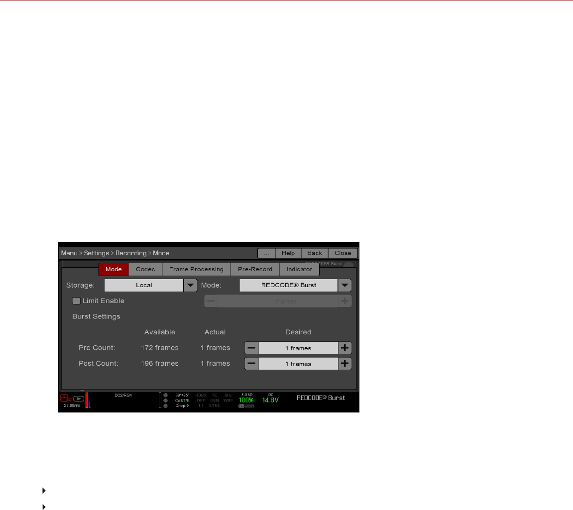
REDCODE BURST
NOTE: This mode is not available in Stills mode.
NOTE: Audio is not recorded in REDCODE Burst mode.
In REDCODE Burst mode, the camera can record at a lower compression (REDCODE) for the specified amount of
frames. When REDCODE Burst mode is enabled and recording starts, the camera captures a “burst” of frames at the
lower REDCODE, and then continues to record at the next available REDCODE. To add more bursts to clips during
recording, press any key mapped to “Record: Mark Frame”.
To use REDCODE Burst mode, follow the instructions below:
1. Go to Menu > Settings > Recording > Mode.
2. Select REDCODE Burst from the Mode drop-down menu.
3. Use the Limit Recording to fields to set the recording to end at a predefined frame limit (optional).
4. Select a Pre Count and Post Count. For more information, go to "Pre Count and Post Count" below.
5. Close the menu.
6. Start recording.
Figure: REDCODE Burst
PRE COUNT AND POST COUNT
When Frame Trigger or Burst mode is enabled, select the number of frames for the Pre Count and Post Count:
Pre Count: The camera captures the frame cache from the time preceding the marker.
Post Count: The camera captures the remaining frame cache after the marker.
The maximum frame counts are listed in the Available column, and are based on format and REDCODE.
C OPYR I GHT © 2 01 9 R ED. C OM , LLC 955- 0159_V 7. 1, R EV -G | 126
EPIC-W GEMINI OPERATION GUIDE

MULTI-SHOT
NOTE: The camera does not sync timecode in Multi-Shot mode.
NOTE: This mode is available in Motion mode, but is only recommended in Stills mode.
NOTE: Audio is not recorded in Multi-Shot mode.
Multi-Shot mode removes restrictions on Recording Frame Rate and REDCODE, allowing you to shoot at a high
resolution, high frame rate, and low compression. These restrictions are removed because the camera records first to
the camera’s memory, and then offloads (while recording) to SSD after the camera’s buffer fills up. Since the camera
records only as fast as the buffer can transfer data, frames are dropped from the clip.
Multi-Shot mode has two sub-modes:
Basic Multi-Shot mode
Advanced Multi-Shot mode
BASIC MULTI-SHOT MODE
In Basic Multi-Shot mode, you can record a one-frame clip by pressing a Record key, or you can continuously record
frames by holding a Record key. This mode is the easiest way to shoot stills, but there is some latency (about 700
milliseconds) when you press Record.
This mode only involves the Record key on the media bay.
Pressing the PWR/REC key on the camera initiates Advanced Multi-Shot mode.
To use Basic Multi-Shot mode, perform one of the following:
Press a Record key to record a one-frame clip.
Press and hold a Record key to start a new clip and continuously add frames to that clip. Release the Record key
to stop adding frames and end the clip.
ADVANCED MULTI-SHOT MODE
In this mode, the camera is continuously recording, but is not saving frames. This eliminates the delay you get in Basic
Multi-Shot mode. Since the camera is continuously recording, the camera requires the same amount of power it does
during Continuous Record (as opposed to Preview mode). Unlike Basic mode, all frames are added to one (1) clip,
instead of to separate clips.
To use Advanced Multi-Shot mode, follow the instructions below:
1. Press the PWR/REC key on the camera to start a new clip. This initial press adds one (1) frame to the clip.
2. Press the Record key on the media bay to add frames to the clip:
Press a Record key once to add a few frames to the clip. (The number of frames varies, and depends on the
buffer.)
Press and hold a Record key to continuously add frames; release the Record key to stop adding frames.
3. Press the PWR/REC key on the camera to end the clip.
NOTE: You cannot shut down the camera until you end the clip.
C OPYR I GHT © 2 01 9 R ED. C OM , LLC 955- 0159_V 7. 1, R EV -G | 127
EPIC-W GEMINI OPERATION GUIDE

ENABLE MULTI-SHOT MODE
To enable Multi-Shot mode, follow the instructions below:
1. Set the camera to Stills mode. For more information, go to "Camera Mode" on page67.
2. Go to Menu > Settings > Recording > Mode.
3. Select Multi-Shot from the Mode drop-down menu.
4. Use the Limit Recording to fields to set the recording to end at a predefined frame limit (optional).
5. Close the menu.
MOTION + STILLS
NOTE: This mode is available in Motion mode, but is only recommended in Stills mode.
Motion + Stills mode is identical to Continuous Record, except that when you initiate recording by pressing the
PWR/REC key on the camera, all other Record keys mark frames for the duration of the clip. (If you initiate recording
by pressing any other Record key, you can press any key mapped to “Record: Mark Frame” to mark stills.)
To use Motion + Stills mode, follow the instructions below:
1. Set the camera to Stills mode. For more information, go to "Camera Mode" on page67.
2. Go to Menu > Settings > Recording > Mode.
3. Select Motion + Stills from the Mode drop-down menu.
4. Use the Limit Recording to fields to set the recording to end at a predefined frame limit (optional).
5. Close the menu.
6. Press the PWR/REC key on the camera to start recording.
7. Press the Record key on the media bay to mark a frame.
8. Press the PWR/REC key on the camera to stop recording.
C OPYR I GHT © 2 01 9 R ED. C OM , LLC 955- 0159_V 7. 1, R EV -G | 128
EPIC-W GEMINI OPERATION GUIDE

APPLE PRORES INFORMATION
By default, the camera records all videos and stills in the REDCODE RAW file format (records R3D files). You also
have the option to record Apple ProRes files. This section provides general information about recording Apple ProRes
files with the camera:
NOTE: If Look Around is enabled, the Look Around area is recorded in the Apple ProRes file.
Selecting a Recording Frame Rate that is not supported by Apple ProRes has the following effects:
2K Apple ProRes over 120 FPS: The QuickTime file will be sub-sampled.
The camera cannot record Apple ProRes when Pre-Record is enabled.
The camera can record Apple ProRes only when either of the following recording modes is enabled:
Continuous Record
Motion + Stills
Recording 4K Apple ProRes is only available:
When recording to Apple ProRes only
When recording to the following codecs:
Apple ProRes 422
Apple ProRes 422 HQ
Apple ProRes 422 LT
If HDRX® is enabled, only the selected monitor track is recorded to the QuickTime files. For more information, go
to "HDRX Menu" on page136.
RED recommends performing a Secure Format before recording Apple ProRes. For more information, see the
DSMC Media Operation Guide, available at www.red.com/downloads.
QuickTime files have the same metadata that is in the REDCODE RAW files. The metadata is per clip, and not per
frame. At this time, there is no tool for extracting that metadata from the QuickTime files.
You can select any resolution. When recording Apple ProRes, the camera scales that format to the Resolution (2K)
selected in the Codec menu. The field of view is maintained in the QuickTime file; the image is not cropped.
If recording 4K Apple ProRes and the Resolution is less than 4K, the image is scaled to 2K.
For more information about Apple ProRes, including the data rates for each codec, see the Apple Support site at
https://support.apple.com/en-us/HT202410.
To record Apple ProRes files, go to "Select Record File Format" on page133.
C OPYR I GHT © 2 01 9 R ED. C OM , LLC 955- 0159_V 7. 1, R EV -G | 129
EPIC-W GEMINI OPERATION GUIDE
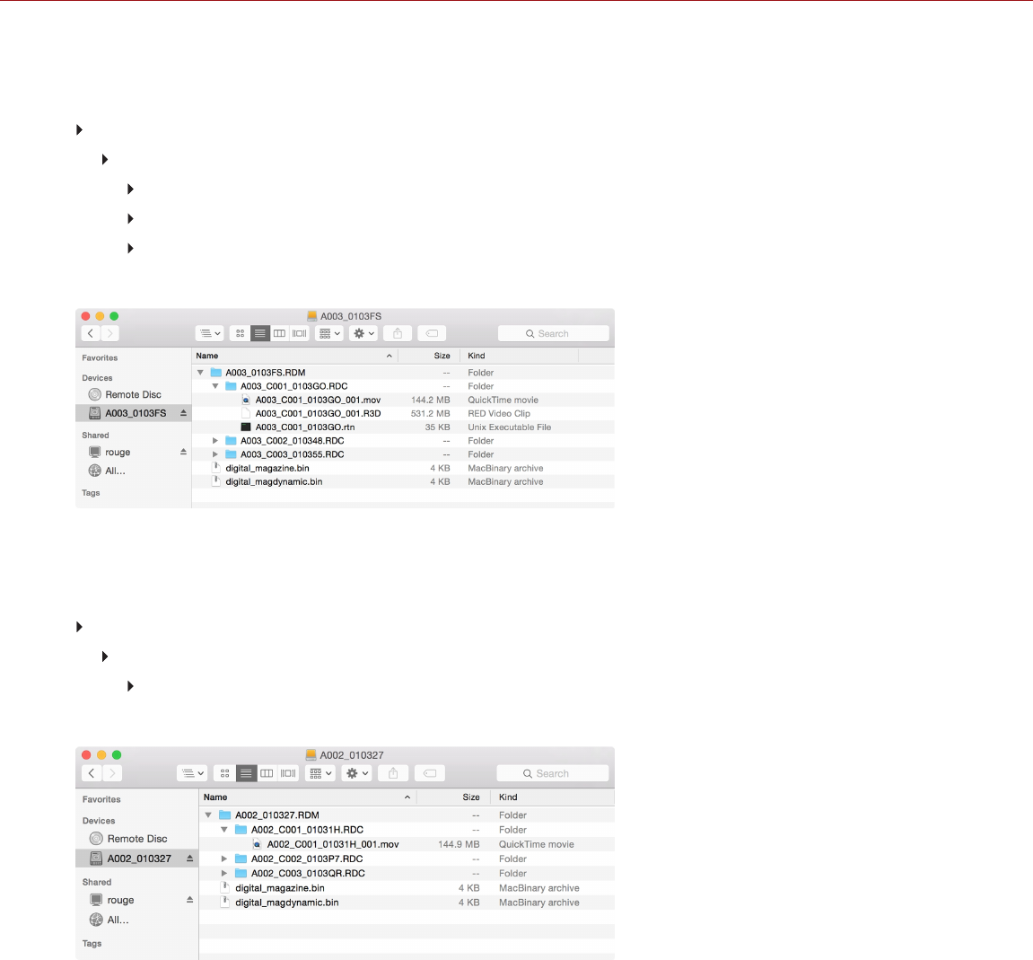
FILE STRUCTURE OF RECORDED APPLE PRORES FILES
When recording R3D + Apple ProRes, this is the file structure of the recorded files on the SSD (when the SSD is
formatted as FAT32):
.RDM Folder
.RDC Folder
.mov
.R3D
.rtn (RED Thumbnail file)
NOTE: The camera creates mulitple .mov files, similar to how the camera creates multiple R3D files.
Figure: File Structure: R3D + Apple ProRes
When recording Apple ProRes only, this is the file structure of the recorded files on the SSD (when the SSD is
formatted as FAT32):
.RDM Folder
.RDC Folder
.mov
NOTE: The camera creates mulitple .mov files, similar to how the camera creates multiple R3D files.
Figure: File Structure: Apple ProRes
C OPYR I GHT © 2 01 9 R ED. C OM , LLC 955- 0159_V 7. 1, R EV -G | 130
EPIC-W GEMINI OPERATION GUIDE

AVID DNXHD AND AVID DNXHR INFORMATION
By default, the camera records all videos and stills in the REDCODE RAW file format (records R3D files). You also
have the option to record to Avid DNxHD and Avid DNxHR (records .mxf files). This section provides general
information about recording Avid DNxHD/HR with the camera:
NOTE: If Look Around is enabled, the Look Around area is recorded in the Avid DNxHD/HR file.
NOTE: Enabling Look Around effects the aspect ratio of the scaled file, regardless of the recorded area.
Selecting a Recording Frame Rate that is not supported by Avid DNxHD/HR causes the codec file to be sub-
sampled to half of the selected Recording Frame Rate.
The camera cannot record Avid DNxHD/HR when Pre-Record is enabled.
The camera can record Avid DNxHD/HR only when either of the following recording modes is enabled:
Continuous Record
Motion + Stills
If HDRX® is enabled, only the selected monitor track is recorded to the Avid DNxHD/HR file. For more information,
go to "HDRX Menu" on page136
RED recommends performing a Secure Format before recording Avid DNxHD/HR. For more information, see the
DSMC Media Operation Guide, available at www.red.com/downloads.
The .mxf files have the same metadata that is in the REDCODE RAW files. The metadata is per clip, and not per
frame. At this time, there is no tool for extracting that metadata from the .mxf files.
You can select any resolution. When recording Avid DNxHD/HR, the camera scales that format to the Resolution
(2K or 4K) selected in the Codec menu. The field of view is maintained in Avid DNxHD/HR; the image is not
cropped.
If recording 4K Avid DNxHD/HR and the Resolution is less than 4K, the image is scaled to 2K.
For more information about Avid DNxHD/HR, see the Avid website at www.avid.com/en/products/avid-dnxhr-and-
dnxhd.
To record Avid DNxHD/HR, go to "Select Record File Format" on page133.
AVID DNXHD AND AVID DNXHR DESCRIPTION
The table below describes each Avid DNxHD/HR codec.
NAME CODEC ID BITS COLOR
DNxHR HQX 1271 12 bit YCbCr 4:2:2
DNxHR HQ 1272 8 bit YCbCr 4:2:2
DNxHR SQ 1273 8 bit YCbCr 4:2:2
DNxHR 444 1270 12 bit RGB 4:4:4
DNxHD 444 1256 10 bit RGB 4:4:4
DNxHD HQX 1235 10 bit YCbCr 4:2:2
DNxHD HQ 1238 8 bit YCbCr 4:2:2
DNxHD SQ 1237 8 bit YCbCr 4:2:2
C OPYR I GHT © 2 01 9 R ED. C OM , LLC 955- 0159_V 7. 1, R EV -G | 131
EPIC-W GEMINI OPERATION GUIDE
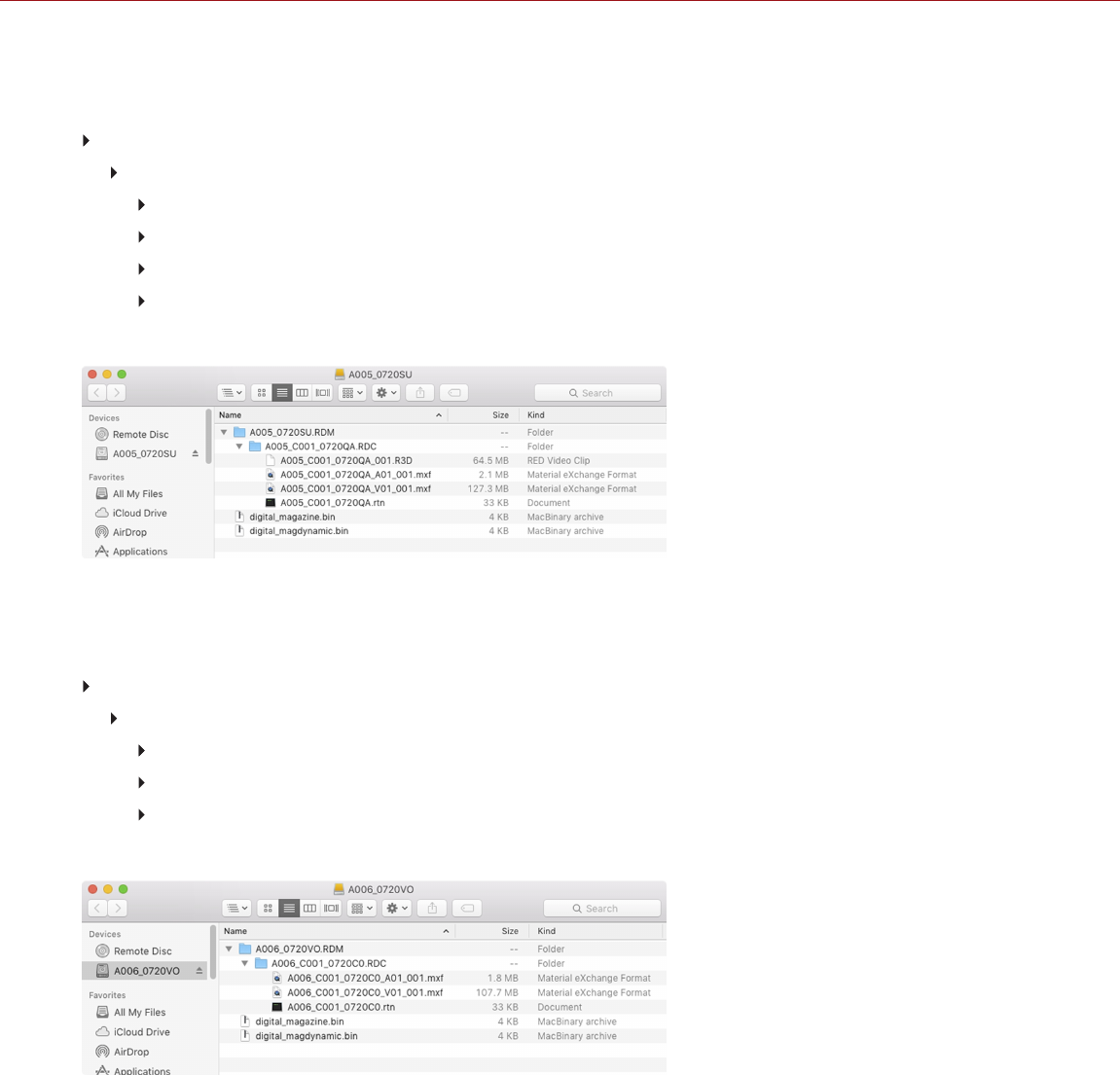
FILE STRUCTURE OF RECORDED AVID CODEC FILES
When recording R3D + Avid DNxHD/HR, this is the file structure of the recorded files on the SSD (when the SSD is
formatted as FAT32):
.RDM Folder
.RDC Folder
.R3D
.mxf (audio file, marked with an “A”)
.mxf (video file, marked with a “V”)
.rtn (RED Thumbnail file)
NOTE: The camera creates mulitple .mxf files, similar to how the camera creates multiple R3D files.
Figure: File Structure: R3D + DNxHD/HR
When recording Avid DNxHD/HR only, this is the file structure of the recorded files on the SSD (when the SSD is
formatted as FAT32):
.RDM Folder
.RDC Folder
.mxf (audio file, marked with an “A”)
.mxf (video file, marked with a “V”)
.rtn (RED Thumbnail file)
NOTE: The camera creates mulitple .mxf files, similar to how the camera creates multiple R3D files.
Figure: File Structure: R3D + DNxHD/HR
C OPYR I GHT © 2 01 9 R ED. C OM , LLC 955- 0159_V 7. 1, R EV -G | 132
EPIC-W GEMINI OPERATION GUIDE

SELECT RECORD FILE FORMAT
NOTE: For more information on which codecs your camera offers, go to "Technical Specifications" on page211.
To select what file formats to record to, follow the instructions below.
1. Go to Menu > Settings > Recording > Codec.
2. Select the file format(s) you want to record to from the Record File Format drop-down menu:
R3D
R3D + Apple ProRes
R3D + Avid DNxHD/HR
Apple ProRes
Avid DNxHD/HR
The selected file format displays in the Lower Status Row.
3. R3D: Select a target REDCODE compression ratio from the REDCODE menu. For more information, go to
"REDCODE" on page62.
4. Apple ProRes or Avid DNxHD/HR: Select a resolution from the Resolution drop-down menu.
5. Apple ProRes or Avid DNxHD/HR: Select a codec from the Record Video Codec drop-down menu.
6. Apple ProRes or Avid DNxHD/HR: If the camera is in IPP2 mode, select an option from the Baked-in Settings
drop-down menu. This determines which image settings are irreversibly encoded (baked) as image data in the
recorded file. For more information on the options in this menu, go to "Baked-In Settings" below.
NOTE: Although the "All Image Settings" is an option when 4K is selected within the Resolution drop-down menu,
this option can only be applied with 2K output. If 4K and "All Image Settings" are selected at the same time, the
Baked-in Settings turns red and yellow as a warning, and the settings are NOT applied.
BAKED-IN SETTINGS
If the camera is in IPP2 mode and you are recording to a 2K Apple ProRes or 2K Avid DNxHD/HR codec, you can
irreversibly encode (bake) certain image settings into the recorded file. To bake in settings, select one of the following
options from the Baked-in Settings drop-down menu:
Primary Only: Only bakes the ISO, Color Temperature, Tint, and Exposure Adjust settings into the recorded file.
Does NOT bake in the 3D LUT and other image settings.
All Image Settings: Bakes all image settings into the recorded file, including the Primary Raw Development,
Grading, and Output Transform stages. This includes the 3D LUT, CDLs, and output color space. For more
information on the different IPP2 stages, see the IPP2: Image Pipeline Stages white paper at
www.red.com/downloads. With the All Image Settings option, you can select either SDR or HDR to control the tone
curve for standard dynamic range (SDR) or high dynamic range (HDR) output.
C OPYR I GHT © 2 01 9 R ED. C OM , LLC 955- 0159_V 7. 1, R EV -G | 133
EPIC-W GEMINI OPERATION GUIDE

FRAME PROCESSING
NOTE: Frame processing is not supported in Speed Ramp Mode. For more information, go to "Speed Ramp Mode"
on page125.
Frame processing allows for the combination of multiple captured frames into one recorded frame. The combination
occurs before the resulting frame is encoded. You can select the following frame processing settings: No Frame
Processing, Frame Summing, Frame Averaging.
When in Frame Summing mode or Frame Averaging mode, the current integration time is applied to each frame. This
means if the integration time is not the entire frame time (or 360°) there are gaps between the images used to create the
combined frame. This may lead to unexpected motion artifacts.
The effect of frame processing is only visible during record. In Frame Summing mode, this means the exposure
changes between preview and record. Experiment with the exposure and frame processing settings to achieve the
effect you want.
NO FRAME PROCESSING
Normal frame processing mode. The Frames to Process selection does not affect recording.
FRAME SUMMING
Frame Summing combines the specified number of frames into one frame, and adds together the exposure time for
each of the original frames. The resulting frame has an effective integration time that is equal to the current integration
time multiplied by the number of frames.
For example, if you select 16 as the Frames to Process value, and set exposure to 1/48 sec, the resulting image has
an effective integration time of 1/3 sec (16 x 1/48).
Frame summing results in a final image that is brighter and possibly blurrier than any of the original frames, so you can
use frame summing to achieve the effect of long-exposure.
FRAME AVERAGING
Frame Averaging combines the specified number of frames into one frame, and averages the exposure time for each
of the original frames. The resulting frame has an effective integration time that is equal to the current integration time.
For example, if you select 2 as the Frames to Process value, and set exposure to 1/48 sec, the resulting image still
has the exposure value of 1/48 sec, along with the effect of long-exposure.
You can use frame averaging to achieve the effect of long-exposure along with the benefits of reduced noise.
However, frame averaging does affect motion blur characteristics.
C OPYR I GHT © 2 01 9 R ED. C OM , LLC 955- 0159_V 7. 1, R EV -G | 134
EPIC-W GEMINI OPERATION GUIDE

PRE-RECORD
To set up Pre-Record, go to Menu > Settings > Recording > Pre-Record.
When enabled, the Pre-Record setting continuously captures a cache of footage before recording starts. Select to
have 4 to 30 seconds (incremented at two second intervals) of pre-record time added to the actual footage. When Pre-
Record is enabled, you will not miss the start of a shot by being a little slow on the trigger.
Pre-Record Duration: Select the pre-record time.
Always trigger Pre-Record before recording: When selected, Pre-Record always starts when recording starts:
Press PWR/REC to activate Pre-Record.
Press PWR/REC a second time to start recording.
Press PWR/REC a third time to stop recording.
Trigger Pre-Record Now: When selected, the Pre-Record menu closes and Pre-Record mode starts.
NOTE: Always perform a Secure Format before using Pre-Record. A Secure Format restores the SSD back to factory
out-of-box settings, and optimizes the SSD for Pre-Record.
NOTE: Pre-Record puts your SSD in a state of constant record. As with any SSD technology, continuously writing
data over an extended period of time will impact the lifespan of the media.
NOTE: To use Pre-Record only for specific situations, map Pre-Record to a key (Menu > Settings > Setup > Keys >
Record: Start Pre-Record). For more information, go to "Keys" on page142.
INDICATOR
Enable Sounds: Select this check box to enable sounds. Then select sounds for the following actions:
Record Start
Record Stop
Tag Still Frame
EVF Tally Light: Enable the EVF Record Tally LED on the EVF to illuminate red when recording.
SSD Tally Light: Enable the Record Tally LED on the media bay to illuminate red when recording. For more
information, go to "RED MINI-MAG System" on page18.
C OPYR I GHT © 2 01 9 R ED. C OM , LLC 955- 0159_V 7. 1, R EV -G | 135
EPIC-W GEMINI OPERATION GUIDE

HDRX MENU
NOTE: HDRX mode cannot be modified when test signals are enabled.
NOTE: You cannot change the exposure when HDRX is enabled.
In HDRx mode, the camera records two (2) exposures within the interval that it would usually record only one (1). The
primary exposure is normal, and uses the standard aperture and shutter settings (the “A track”). The secondary
exposure is typically for highlight protection, and uses an adjustable shutter speed that is 2 to 6 stops faster (the “X
track”). Since the camera captures twice the usual amount of frames, the maximum available recording frame rate is
halved and the REDCODE compression options are limited.
For more information, see the High Dynamic Range Video with HDRX article, available at www.red.com/learn/red-
101/hdrx-high-dynamic-range-video.
HDRX RESTRICTIONS
You cannot use HDRX mode when:
The MOTION MOUNT Shutter Type is set to Soft or Square.
A Sensor Sync Mode (Genlock or MoCo) is enabled.
Speed Ramp mode is enabled.
A Frame Processing mode (Frame Summing or Frame Averaging) is enabled.
Network Storage mode is enabled.
ENABLE HDRX
By default HDRX is disabled, and the HDRX indicator in the Lower Status Row is grey.
To enable HDRX, follow the instructions below:
1. Go to Menu > Settings > HDRX.
2. Select HDRX.
The HDRX text in the Lower Status Row turns white.
3. Select the number of Factors. The range is 1 to 6, and the default is 2.
4. Select which track you want the display to show:
A Track: This track shows the video with the selected aperture and exposure settings applied.
X Track: This track shows the video with the additional stops applied.
C OPYR I GHT © 2 01 9 R ED. C OM , LLC 955- 0159_V 7. 1, R EV -G | 136
EPIC-W GEMINI OPERATION GUIDE

FOCUS MENU
To access the Focus menu, go to Menu > Settings > Focus.
The Focus menu includes: Mode and Rack.
MODE TAB
Use the Mode tab to select a focus setting. To set up focus, follow the instructions below:
1. Go to Menu > Settings > Focus > Mode.
2. Select a mode from the Mode drop-down menu. For more information, go to "Mode" below.
3. Select a zone/target from the Zone drop-down menu. For more information, go to "Zone/Target" below.
4. If using Spot, select a size from the Size drop-down menu. For more information, go to "Size" below.
5. Select a confirm style from the Confirm menu. For more information, go to "Confirm Style" below.
MODE
Select an option from the Mode drop-down menu:
Manual: Enables manual focus. Disables all other settings in the Focus menu.
Confirm: Enables a focus target, which changes color to indicate if the subject in the target is in focus. After
selecting Confirm, set up the target type (zone), size, and confirm style. Inadequate lighting and/or contrast may
decrease the performance of Confirm mode.
Single, Continuous, Touch Track, Rack: For more information, go to "Use Autofocus Modes" on the next page.
ZONE/TARGET
Select an option from the Zone drop-down menu:
Center: A large square centered in the recording area.
Spot: A small target for precise focus that you can move around the recording area. Select a size for the target
from the Size drop-down menu. For information on how to move the Spot target, go to "Move the Spot Focus
Target" on the next page.
SIZE
Select a size for the Spot target from the Size drop-down menu.
CONFIRM STYLE
Select a confirm style from the Confirm Style drop-down menu.
STYLE DESCRIPTION OBJECT IN FOCUS OBJECT OUT OF FOCUS
None Square target Target is yellow or green Target is red
Circle Yellow circle around a
square target
Target is yellow or green; circle is almost the
same size as the square
Target is red; circle gets bigger
Bar Bar target Target is yellow or green; vertical bar on the
right side is filled up
Target is red; vertical bar on the left
side is almost empty
Pie Pie target Target is yellow or green; line around the
curve is filled up
Target is red; line around the curve
is almost empty
C OPYR I GHT © 2 01 9 R ED. C OM , LLC 955- 0159_V 7. 1, R EV -G | 137
EPIC-W GEMINI OPERATION GUIDE

TARGET COLOR
Both the Center and Spot targets change color to indicate if the objects in the target are in focus.
Blue: Camera is focusing
Red: Objects are out of focus
Yellow: Objects are almost in focus
Green: Objects are in focus
MOVE THE SPOT FOCUS TARGET
Move the Spot target with a touchscreen:
Tap and hold the touchscreen on the location where you want to relocate the Spot target.
Tap and hold the touchscreen where the Spot target currently is, and drag the Spot target.
USE AUTOFOCUS MODES
When supported lens mounts and lenses are attached, autofocus modes display in the Mode drop-down menu.
Although the camera supports autofocus, RED recommends using these autofocus modes only as focus assist tools.
Performance may vary from lens to lens. For optimal focus accuracy, use manual focus.
AUTOFOCUS REQUIREMENTS
Autofocus modes are available (in the Mode drop-down menu) in any of the following situations:
A DSMC S35 Nikon Mount and a supported lens is attached. The lens focus switch is set to “A” or “M/A”.
A DSMC Canon Mount and a supported lens is attached. The lens focus switch is set to “AF”.
A DSMC RED MOTION MOUNT S35 Ti Canon (Captive) lens mount and a supported lens is attached. The lens
focus switch is set to “AF”.
AUTOFOCUS MODES
Single: When you press the key mapped to AF: Start, the camera performs single-shot AF. Optimized for rapid
focus even in low-contrast conditions. Works with Center and Spot zones.
Continuous: When you press the key mapped to AF: Start, the camera attempts to keep objects in the target in
focus. Works best with good lighting and contrast. Works with Center and Spot zones.
Touch Track: Dynamically updates a positionable AF point using the touchscreen. Works with Spot zone. Keep
the target on the subject while moving it across frame, since the lens continuously focuses on that target.
Rack: Enables rack focus. Works with Spot zone. For more information, go to "Rack Focus" on the next page.
NOTE: Press the key mapped to AF Mode: Cycle to cycle through the autofocus modes.
C OPYR I GHT © 2 01 9 R ED. C OM , LLC 955- 0159_V 7. 1, R EV -G | 138
EPIC-W GEMINI OPERATION GUIDE

AUTOFOCUS PERFORMANCE
Autofocus performance may be reduced in the following conditions:
Subject is too dark or distant.
Subject is too bright or close.
Inadequate contrast between the subject and background.
Inadequate surface contrast or detail.
Scene has reflective highlights.
Subject is backlit.
NOTE: Use Edge mode for assistance in these conditions. For more information, go to "False Color Modes: Edge"
on page97.
RACK FOCUS
Use the Rack tab to set up rack focus.
SET UP RACK FOCUS
1. Ensure that a DSMC Nikon Mount, DSMC Canon Mount, or DSMC RED MOTION MOUNT S35 Ti Canon (Captive)
lens mount and a supported lens are attached to the camera.
2. Go to Menu > Settings > Focus > Mode.
3. Select Rack from the Mode drop-down menu.
4. Select a size from the Size drop-down menu.
5. Go to the Rack tab.
6. Use the Rack Speed slider to change the speed at which the lens moves. Move the slider to the left for a slower
speed, and to the right for a faster speed.
7. Enable up to four (4) Rack Points.
8. To set a rack point location, follow the instructions below:
A. Select the rack point: A, B, C, or D.
B. Select Close.
C. Press and hold the touchscreen where you want the rack point to be, or press and drag the rack point. When
you move a rack point, the camera autofocuses.
NOTE: To prevent a rack point from being accidentally moved, the rack point is less sensitive to touch than other
focus targets.
NOTE: To view the focus distance for each rack point on the main screen, enable Rack Show Distance mode.
For more information, go to "Lens" on page152.
9. Select another rack point by performing any of the following actions:
Select another rack point on the touchscreen.
Press the key mapped to AF: Start to cycle to the next rack point in order (A, B, C, and D). For example, if
rack point A is selected when you trigger the AF: Start action, the focus racks from point A to point B.
Press a key that is mapped to racking to a specific rack point.
MAP KEYS FOR RACK FOCUS
The camera offers multiple rack focus actions that you can map to user keys. In the Key menu, searching for "rack"
shows all rack focus actions. For more information, go to "Keys" on page142.
C OPYR I GHT © 2 01 9 R ED. C OM , LLC 955- 0159_V 7. 1, R EV -G | 139
EPIC-W GEMINI OPERATION GUIDE

EXPOSURE ASSIST MENU
To access the Exposure Assist menu, go to Menu > Settings > Exposure Assist.
The Exposure Assist menu provides access to settings for the Auto Exposure (AE) feature. The AE feature maintains a
constant image brightness, even if the actual scene brightness changes.
The AE feature is different than traditional AE, in that RED AE only controls the amount of light that hits the sensor,
either by adjusting aperture or exposure. RED AE analyzes RAW data before the ISO curve, and ensures that the
sensor matches the user-selected brightness.
AUTO EXPOSURE MODES
The Exposure Assist modes determine when the AE tools go into effect:
Off: The AE tools are not enabled.
Single Shot: Map one of the following actions to trigger the AE tools:
AE: Start
AE/AF: Start
Continuous in Preview: The AE tools are enabled in preview only.
Continuous in Preview/Record: The AE tools are enabled in both preview and record.
NOTE: In Stills mode, AE/AF: Start is mapped to Record Half Press by default. For more information, go to "Default
Key Functions" on page264.
EXPOSURE PRIORITY
Manual: You have full control of aperture and shutter. (Default)
Auto: The camera sets the aperture and shutter to meet the selected exposure.
Av (Aperture Value): You set the aperture, and then the camera sets the shutter to meet the selected exposure.
Tv (Time Value): You set the shutter, and then the camera sets the aperture to meet the selected exposure.
EXP COMP AND EV SHIFT
Use the Exp Comp (Exposure Compensation) slider and the EV Shift setting to adjust the brightness of the image.
The default setting of zero (0) attempts to match the average brightness on an 18% grey-target. When AE is enabled,
the target and current measured brightness for the selected metering area display in the histogram as a grey and white
line, respectively.
You can also map these actions to user keys:
AE: Decrease EV Offset: Reduces the EV Offset in increments of 0.2.
AE: Increase EV Offset: Increases the EV Offset in increments of 0.2.
METERING MODE
Metering determines the area of the sensor that is used for brightness evaluation:
Spot: Weights the measurement to the center 5% of the sensor, approximately.
Center: Weights the measurement to the center 25% of the sensor, approximately.
Average: Averages the entire image area of the sensor.
C OPYR I GHT © 2 01 9 R ED. C OM , LLC 955- 0159_V 7. 1, R EV -G | 140
EPIC-W GEMINI OPERATION GUIDE

SPEED
The Speed setting determines how quickly the algorithm adapts to changing light.
Slow: Settings adapt in small steps. Use this setting for fewer and gradual adjustments.
Normal: Settings adapt in medium steps.
Fast: Settings adapt in large steps.
SELECTION
The Selection setting determines which values the algorithm uses. This enables you to modify the list of values so that
the algorithm selects only specific parameters. Use Free Value Selection to improve accuracy.
For example, you can modify the aperture list to include f/2.8 and f/5.6. If Free Value Selection is enabled, the
algorithm only selects aperture parameters between f/2.8 and f/5.6. This setting limits the range of focal depth.
AE INDICATORS
When the AE feature is able to match the sensor brightness, the overlay turns yellow. If the brightness fluctuates more
than half of a stop, the overlay turns red.
When AE is enabled, the “AE” indicator displays before the aperture and exposure parameters in the Upper Status
Row. The user-selected brightness and current measured brightness display in the histogram as grey and white lines,
respectively.
AE LIMITS
All limits, includes custom modifications made to available menu items, are taken into account when AE is active. For
example, if you modify the available list of exposure values, only those values are considered.
C OPYR I GHT © 2 01 9 R ED. C OM , LLC 955- 0159_V 7. 1, R EV -G | 141
EPIC-W GEMINI OPERATION GUIDE
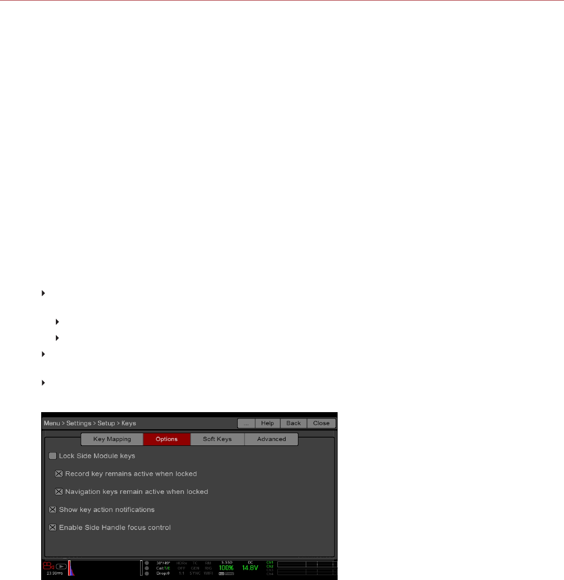
SETUP
The Setup menu includes: Keys, Date/Time, Communication, GPIO/Sync, Fan Control, Lens, and Motor Control.
KEYS
Map keys to often-used actions to easily control the camera. For a full list of the default key mappings, go to "Default
Key Functions" on page264.
NOTE: If using a third-party module, the default GPI functions may match the inputs offered by the module (instead of
the RED defaults).
KEY MAPPING
To map or remap a user key:
1. Press the user key that you want to map.
2. Select an action from the Press (or CCW) drop-down menu that you want to map to the user key.
3. To un-map a key, select -Key Disabled- from the drop-down menu.
4. If you want, map a Release or (CW) action to the key.
A Release action occurs when a pressed key is released.
OPTIONS
Lock Side Module keys: None of the module keys perform any actions when pressed, unless you set up the
exceptions below:
Record key remains active when locked
Navigation keys remain active when locked
Show key action notifications: A notification displays on the bottom of the display when you perform an action
mapped to a key.
Enable Side Handle focus control: Enables the Focus Control Wheel on the DSMC2 Side Handle. For more
information, go to "DSMC2 Side Handle" on page79.
Figure: Key Options
C OPYR I GHT © 2 01 9 R ED. C OM , LLC 955- 0159_V 7. 1, R EV -G | 142
EPIC-W GEMINI OPERATION GUIDE

SOFT KEYS
The following sets of soft keys are available on the touchscreen:
A, B, C, D: Left side of the touchscreen
1, 2, 3, 4: Right side of the touchscreen
To map or remap a soft key, select an action from the drop-down menu next to the key you want to map.
Enable Soft Keys on touchscreen: Tap the left or right side of the touchscreen to show the soft keys.
Show key actions as labels: When the soft keys display, the number/letter of the key and the key action display.
ADVANCED
Use the Advanced tab to map any key, even if the key is not currently accessible.
WARNING: It is possible to remap the navigation keys using this tab. However, if you do not have a touchscreen
attached, it is possible to lock out control. Be careful when remapping navigation keys.
DATE/TIME
Use the Date/Time menu to reset the internal clock of the camera. The time and date are timestamps on R3D® files
when recording to an SSD. The camera uses the 24-hour clock convention (military time). For example, enter 2:35 p.m.
as 14:35:00.
The date and time are saved when you close the Date/Time menu.
COMMUNICATION
Use the Communication menu to allow one (1) or more cameras to communicate with each other or external devices.
You can use the serial port or a direct Ethernet cable to connect two (2) cameras, or one (1) camera and one (1) external
device. If the camera is connected via Ethernet to a hub or router, multiple cameras and devices can communicate with
each other.
For example, on a multi-rig 3D shoot, you can send commands to an individual camera (Example: Set CAM_A_L to
1/48 exposure), to a group of cameras (Example: Set 3DRIG_A to 48 fps), or to all cameras (Example: Start Recording
on all cameras).
CAMERA
To access the Camera menu, go to Menu > Settings > Setup > Communication.
Use the Camera menu to set up a unique identifier for your camera (or a group of cameras). All command filtering
happens on the receiver side of the communication link. Use camera names and group names to address commands
to a specific camera or group of networked cameras.
Camera ID: Enter a unique camera name to use in network communications. The field is limited to eight (8)
characters.
Group ID: Enter a group name to identify the camera as a member of a group of devices. The field is limited to
eight (8) characters, and the default name is DEFAULT.
Target: Specify which devices the camera can send commands to:
All: The camera can send commands to all devices on the network.
None: The camera can only receive commands. The camera cannot send commands.
Custom: The camera can send commands to a specific camera/device (enter the name of the camera/device in
the Target ID text box) or a specific group (enter the name of the group in the Target ID text box). The
camera/group name must match the name entered in the Camera/Group field of the target device(s).
C OPYR I GHT © 2 01 9 R ED. C OM , LLC 955- 0159_V 7. 1, R EV -G | 143
EPIC-W GEMINI OPERATION GUIDE

SERIAL
NOTE: CTRL and GIG-E ports are only available on specific DSMC2 expanders and modules. For more information,
go to "Input/Output Connectors" on page219.
To access the Serial menu, go to Menu > Settings > Setup > Communication > Serial.
The camera can communicate to external devices via the CTRL and the GIG-E connectors (camera-to-camera
communication is possible only via GIG-E).
Select one of the following protocols from the Serial Protocol drop-down menu:
None (Default)
Element Technica
3ality SPC 7XXX
RED Command Protocol
ETHERNET
NOTE: Using Ethernet requires a GIG-E port, which is available on the DSMC2 Jetpack-SDI Expander, DSMC2
REDVOLT Expander, and DSMC2 Production Module. For more information, go to "Input/Output Connectors" on
page219.
To set up the Ethernet settings, go to Menu > Settings > Setup > Communication > Ethernet.
Each camera or device requires a unique IP address. For camera-to-camera communication via Ethernet, both cameras
need to be in the same sub-net (have the same netmask address) and have the same gateway address.
Enable DHCP: Enables DHCP. If a DHCP-server is available in the communications network, the camera obtains
an IP address, netmask address, and gateway address automatically from the DHCP server. You cannot manually
enter anything in the IP Address, Netmask, and Gateway fields when this check box is selected.
Enable Camera to Camera: A change to settings on this camera is sent to other cameras via the network as a
SET command (as UDP packets). The SET command then sets the property on other cameras. If this camera
receives a SET command, the camera does not send the command to other cameras/devices.
Enable External Control: This camera can be controlled via TCP/IP from an external device.
C OPYR I GHT © 2 01 9 R ED. C OM , LLC 955- 0159_V 7. 1, R EV -G | 144
EPIC-W GEMINI OPERATION GUIDE
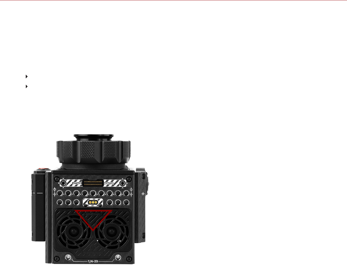
WIRELESS CONNECTION
The camera offers a wireless (802.11g) connection that provides communication support for third-party applications.
The camera uses the RED Command Protocol (R.C.P.) to communicate information between the camera and an
application. As with all wireless devices, the communication range may be affected by the environment and any radio
frequency (RF) interference that may be present. The wireless frequency is 2.4 GHz. For optimal performance, do not
obstruct the antenna with any accessory, mounting plate, or mounting rail.
There are two (2) ways to connect the camera to a device:
Ad-Hoc mode: The camera and your device connect to each other.
Infrastructure mode: The camera and your device both connect to an access point, and communicate through
that wireless network.
NOTE: To connect the camera to an app, the app must have been programmed using the R.C.P. SDK, which is
available through the R.C.P. Development Kit.
NOTE: The wireless antenna is integrated into the fan grill (top side of camera).
Figure: Do Not Obstruct WiFi Antenna
C OPYR I GHT © 2 01 9 R ED. C OM , LLC 955- 0159_V 7. 1, R EV -G | 145
EPIC-W GEMINI OPERATION GUIDE
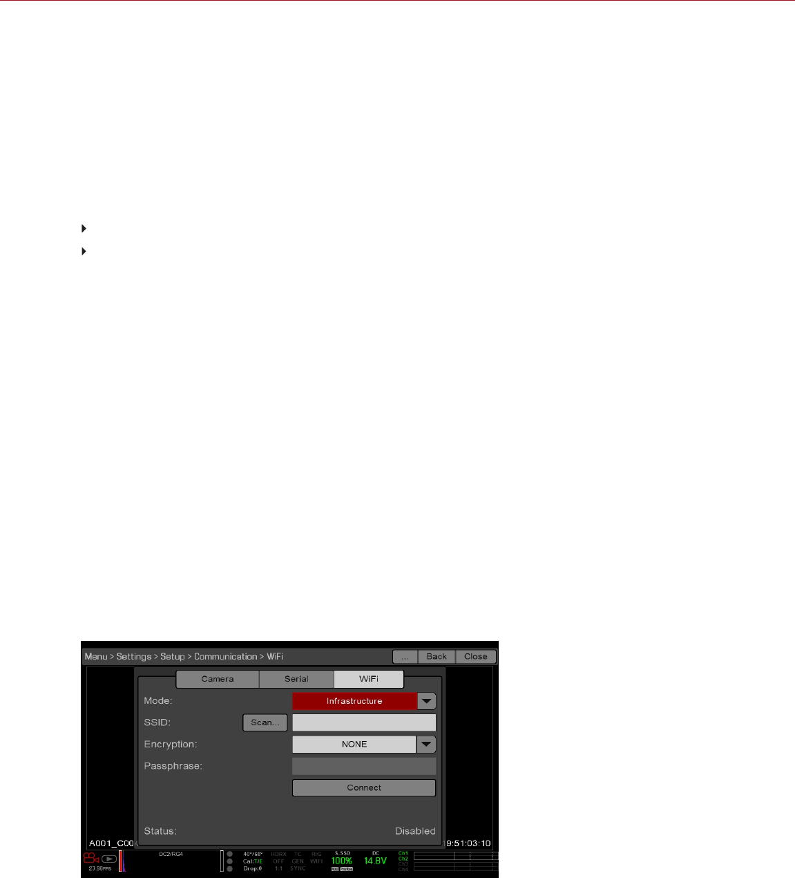
CONNECT WIRELESSLY TO A DEVICE VIA AD-HOC MODE
In Ad-Hoc mode, the camera and your device connect to each other. To connect the camera to your device via an ad-
hoc network, follow the instructions below:
1. Go to Menu > Settings > Setup > Communication.
2. Select the WiFi tab.
3. Select Ad-Hoc from the Mode drop-down menu.
4. Select a wireless channel from the Channel drop-down menu. The default is Ch1, and you can select one out of
11 channels.
5. Select a security option from the Encryption drop-down menu:
NONE: The connection will be unsecured.
WPA2: The connection will be encrypted via WPA2.
6. If you selected WPA2 as the encryption option, type the passphrase that will be required to access the network.
7. Close the WiFi screen.
8. Connect your device to the ad-hoc network created by the camera. The steps in this procedure depend on what
type of device and operating system you are using. For example, if you are connecting an iOS device, go to
Settings > Wi-Fi > Devices, and select the camera name.
The camera name displays on the WiFi screen in-camera. The camera and your device are now connected.
NOTE: If you created a passphrase for the network, you will need to enter that passphrase.
CONNECT WIRELESSLY TO A DEVICE VIA INFRASTRUCTURE MODE
In Infrastructure mode, the camera and your device both connect to an access point, and communicate through that
wireless network. The camera can connect to access points that are not encrypted, use WPA encryption, or use WPA2
encryption. To connect the camera to your device via an existing wireless network, follow the instructions below:
1. Connect your device to a wireless network. The access point for the network must have DHCP enabled.
2. Make sure that you know the name and password for the network, since you will need that information to connect
the camera to the same network.
3. Go to Menu > Settings > Setup > Communication.
4. Select the WiFi tab.
5. Select Infrastructure from the Mode drop-down menu.
Figure: WiFi Menu
C OPYR I GHT © 2 01 9 R ED. C OM , LLC 955- 0159_V 7. 1, R EV -G | 146
EPIC-W GEMINI OPERATION GUIDE
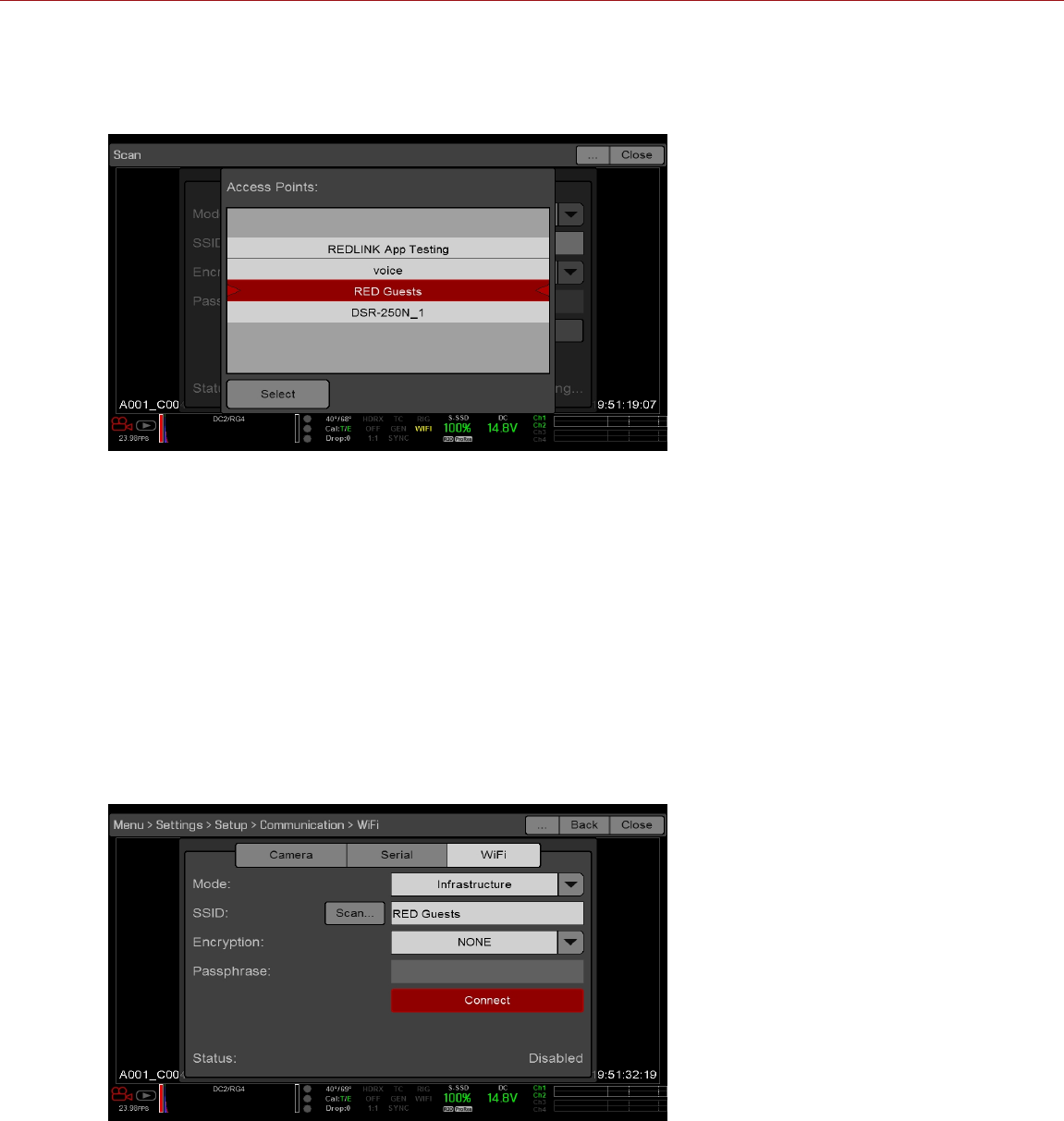
6. Select Scan to search for available wireless networks.
The available wireless networks (access points) display.
7. Highlight the wireless network that your device is connected to and select Select.
Figure: Select Wireless Network
8. If you select an encrypted network, follow the instructions below to enter the passphrase for the network:
A. Select a security option from the Encryption drop-down menu.
B. Tap or select the Passphrase text box.
C. Type the passphrase to access the network.
D. Select OK.
9. To enable/disable DHCP, select IP Config and set up the IP settings. For more information on configuring DHCP
and IP settings, go to "Ethernet" on page144.
10. Select Connect at the bottom of the WiFi screen.
The IP address of the access point displays at the bottom of the WiFi screen after the camera connects to the
access point.
Figure: Select Connect
C OPYR I GHT © 2 01 9 R ED. C OM , LLC 955- 0159_V 7. 1, R EV -G | 147
EPIC-W GEMINI OPERATION GUIDE

11. Connect your device to the same wireless network that the camera is connected to. The steps in this procedure
depend on what type of device and operating system you are using. For example, if you are connecting an iOS
device, go to Settings > Wi-Fi, and select the wireless network.
The camera and your device are now connected.
Figure: Connect to Network
12. To ensure that your app can communicate with the camera, ensure that there is a way to connect your app to a
specific camera. Since there may be multiple cameras in the area, select your specific camera in the app itself.
C OPYR I GHT © 2 01 9 R ED. C OM , LLC 955- 0159_V 7. 1, R EV -G | 148
EPIC-W GEMINI OPERATION GUIDE

GPIO SYNC
NOTE: Using general purpose inputs/outputs and sync requires an expander or module. For more information, go to
"Input/Output Connectors" on page219.
SYNC
Use the Sync menu to set up genlock and Motion Control (MoCo). For more information, go to "Timecode, Genlock,
Multi-Camera Setup" on page174.
NOTE: Using sync and genlock requires an expander or module. For more information, go to "Input/Output
Connectors" on page219.
SENSOR SYNC MODE
Sensor Sync Mode allows the shutter timing (scan start) to sync to an external signal.
Off: Sensor runs at the current recording frame rate. This is the default option.
Genlock: Sensor synchronizes with the incoming compatible genlock signal.
MoCo: Each rising edge on the sync input triggers a frame to be captured.
GENLOCK SOURCE
Select a genlock input:
BRAIN (Default)
Rear Module
BRAIN GPIO
NOTE: Using general purpose inputs/outputs and sync requires an expander or module. For more information, go to
"Input/Output Connectors" on page219.
GPI Function (Camera Input): Select one (1) of the following options to configure the input for devices connected
to the SYNC connector on the camera:
Sync In: The camera input is used as a sync-in signal for MoCo.
General Purpose In: Use the BRAIN GPI In High/Low drop-down menus to map inputs to actions.
GPO Function (Camera Output): Select an option to configure the output for devices connected to the CTRL
connector on the camera:
Sync Out: Provides an output sync signal to act as a shutter start tally.
Recording Indicator Out: Provides a signal when recording is in process.
GEN AND SYNC STATUS INDICATORS
The Lower Status Row of the camera display has GEN and SYNC indicators, which change color based on the current
genlock and sync statuses. For more information, go to "Project Status Indicators" on page69.
C OPYR I GHT © 2 01 9 R ED. C OM , LLC 955- 0159_V 7. 1, R EV -G | 149
EPIC-W GEMINI OPERATION GUIDE

FAN AND TEMPERATURE MANAGEMENT
To select a fan control mode, go to Menu > Settings > Setup > Fan Control.
The camera is controlled by complex thermal algorithms to ensure that the sensor and camera operate at safe
temperatures. Each fan control mode affects the sensor temperature, sensor warm-up time, fan speed, and resulting
fan noise.
When selecting a fan mode, first take into consideration how each fan mode behaves, and then select a fan mode that
fits the needs of your project.
Regardless of sensor type and fan mode, you will get the best image quality by calibrating the sensor at the
temperature that you want to use for your shoot.
FAN CONTROL MODES
Select a fan control mode.
NOTE: After selecting a new fan setting, run the camera until the core temperature stabilizes, and then calibrate the
sensor.
NOTE: Manual mode requires that you actively manage the sensor temperature, because this mode focuses on
controlling fan speed and does not target a narrow sensor temperature range. Use the T/E status indicators as guides
for proper temperature calibration.
NOTE: Maximum speeds are intended as target speeds only; actual fan speeds may be higher at times due to long
recording times or high ambient temperatures.
ADAPTIVE (TARGET TEMPERATURE)
Adaptive is the default mode for the camera.
Select a Target Temperature and the fans self-adjust to maintain the selected temperature. The default Target
Temperature is 39°C. After the camera reaches the Target Temperature, and if the ambient temperature remains
constant, Adaptive mode results in a consistent fan speed and fan noise over time.
Targeting a higher temperature raises the sensor temperature, lengthens the sensor warm-up time, and lowers the fan
speed. Targeting a lower temperature lowers the sensor temperature, shortens the sensor warm-up time, and
increases the fan speed.
NOTE: The intent of Target Temperature is to set the sensor temperature so that you can then create a calibration map
for that temperature.
NOTE: When the camera turns on, the Target Temperature is the temperature of the current calibration map, regardless
of what the Target Temperature was before you turned off the camera. Setting a calibration map also overrides the
Target Temperature. For more information, go to "Sensor Calibration" on page159.
ADAPTIVE PREVIEW QUIET RECORD
Record mode: The camera uses Quiet fan mode. For more information, go to "Quiet" below.
Standby mode: The camera uses Adaptive fan mode. For more information, go to "Adaptive (Target
Temperature)" above.
QUIET
The fans self-adjust to maintain the lowest possible noise level in record and standby mode while still cooling the
camera.
C OPYR I GHT © 2 01 9 R ED. C OM , LLC 955- 0159_V 7. 1, R EV -G | 150
EPIC-W GEMINI OPERATION GUIDE

MANUAL
Select a speed for the fans in both record and standby modes. The fans self-adjust to maintain the selected speeds.
The default Maximum Record Speed is 50% and the default Maximum Preview Speed is 75%. The range for both
Maximum Record Speed and Maximum Preview Speed is 20–100%.
POST RECORD DELAY
Select the amount of time that it takes for the fan to switch from record to preview mode.
C OPYR I GHT © 2 01 9 R ED. C OM , LLC 955- 0159_V 7. 1, R EV -G | 151
EPIC-W GEMINI OPERATION GUIDE
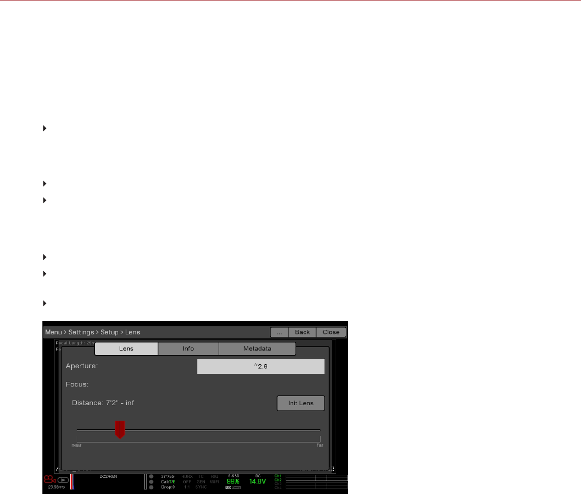
LENS
To access the Lens menu, go to Menu > Settings > Setup > Lens.
LENS TAB
The options displayed on the Lens tab change based on the attached lens mount.
PL MOUNT
Enable Power to Lens: Ensures that the camera powers the lens via the lens mount. This feature is enabled by
default, but the camera saves the last selected setting. Deselect when using a Fujinon® T2.9 Cabrio Premier PL
lens. If you disable this feature for the Fujinon Cabrio, re-enable it when using other lenses. For more information,
go to "Fujinon T2.9 Cabrio Premier PL Lenses" on page253.
Auto-Detect PL Lenses: By default, this feature is enabled.
Detect Lens: Detects a lens, if one is attached.
CANON AND NIKON LENS SETTINGS
The options below display when a DSMC Nikon Mount or DSMC Canon Mount is installed with a supported lens.
Aperture: Enter the aperture value. The range and default depend on the lens.
Focus: Use the slider to change the focal distance. Manually changing the focal distance on the lens itself does
not cause the slider to move. This setting is only available if the lens is in AF mode.
Init Lens: Initializes the lens.
Figure: Lens Menu
C OPYR I GHT © 2 01 9 R ED. C OM , LLC 955- 0159_V 7. 1, R EV -G | 152
EPIC-W GEMINI OPERATION GUIDE
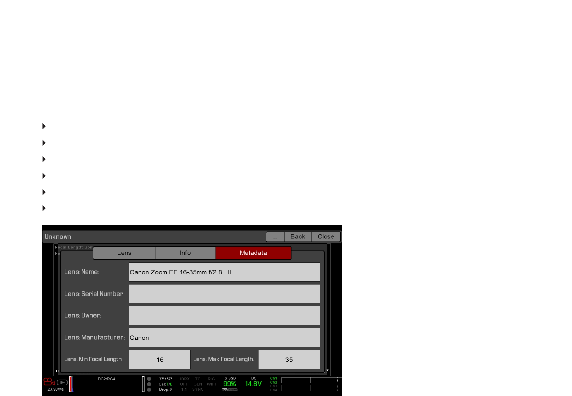
LENS INFO TAB
The Info tab displays the attached lens mount and lens information.
LENS METADATA TAB
If a supported lens is attached, the camera autopopulates some Lens Metadata fields. You can also manually edit the
Lens Metadata fields to describe the attached lens. The information is stored in the clip metadata. The Lens Metadata
fields are:
Lens Name
Lens Serial Number
Lens Owner
Lens Manufacturer
Lens Min Focal Length
Lens Max Focal Length
Figure: Metadata
MOTION MOUNT TAB
The Motion Mount menu is only accessible when a DSMC RED MOTION MOUNT S35 lens mount is installed. For
more information, see the RED MOTION MOUNT Operation Guide, available at www.red.com/downloads.
MOTOR CONTROL
To access the Motor Control menu, go to Menu > Settings > Setup > Motor Control.
This menu is only accessible when the RED 3-Axis Lens Control System is attached. Use the Motor Control menu to
set up the RED 3-Axis Lens Control System. For more information, see the RED 3-Axis Lens Control System
Operation Guide, available at www.red.com/downloads.
C OPYR I GHT © 2 01 9 R ED. C OM , LLC 955- 0159_V 7. 1, R EV -G | 153
EPIC-W GEMINI OPERATION GUIDE

MAINTENANCE
The Maintenance menu includes: Save Log, Upgrade, Calibrate, Self-Test, Restore System, Rediscover, System
Status, and OLPF.
SAVE A LOG FILE
A log file is a detailed text file of the processes and operations performed by the camera. If you contact RED for
support, you may be asked to send a log file.
To save a log file, follow the instructions below:
1. Ensure that an SSD is properly mounted to the camera.
2. Go to Menu > Settings > Maintenance.
3. Select Save Log.
The log file is saved as a *.txt file in the SSD root directory.
For more information about RED support or to create a support ticket, go to https://support.red.com.
NOTE: The camera automatically saves a log file when it is turned off properly and an SSD is mounted.
UPGRADE
To access the Upgrade menu, go to Menu > Settings > Maintenance > Upgrade.
You can check for upgrades for the following items:
Camera: Go to "Upgrade Camera Firmware" on page189.
Media: For more information on the media upgrade procedure, see the DSMC Media Operation Guide, available at
www.red.com/downloads.
CALIBRATE
The Calibrate menu includes:
Sensor: For more information, go to "Sensor Calibration" on page159.
Gyro/Acc: For more information, go to "Gyroscope and Accelerometer Calibration" below.
GYROSCOPE AND ACCELEROMETER CALIBRATION
The internal three-axis gyroscope and three-axis accelerometer need to be calibrated for the Horizon overlay to
function properly. The Gyro/Acc calibration file is stored in the flash memory of the camera, so you DO NOT need to
recalibrate after restoring the camera or upgrading firmware. For more information, go to "Display Modes: Horizon" on
page99.
To calibrate the Horizon overlay, follow the instructions below:
1. Turn on the camera and place it on a level surface.
2. Wait for the camera core temperature to reach room temperature.
3. Go to Menu > Settings > Maintenance > Calibrate > Gyro/Acc and select Low Temperature Calibration.
4. After the calibration finishes, wait for the camera core temperature to reach maximum operating temperature.
5. When the camera reaches maximum operating temperature, select High Temperature Calibration.
C OPYR I GHT © 2 01 9 R ED. C OM , LLC 955- 0159_V 7. 1, R EV -G | 154
EPIC-W GEMINI OPERATION GUIDE

SELF-TEST
The Self-Test menu includes: Enable/Disable Sensor Test Pattern and Touchscreen.
ENABLE/DISABLE SENSOR TEST PATTERN
The Sensor Test Pattern is used during manufacturing and stress testing. For more information, go to "Perform a
Stress Test" on page195. The Sensor Test Pattern is a white screen with vertical lines.
To enable/disable the sensor test pattern, go to Menu > Settings > Maintenance > Self-Test > Enable/Disable
Sensor Test Pattern.
TOUCHSCREEN
To perform a touchscreen self-test, follow the instructions below:
1. Go to Menu > Settings > Maintenance > Self-Test.
2. Select Touchscreen.
A grid of green squares displays on the touchscreen.
3. Touch each box with your finger.
Each green box turns blue.
4. To exit the self-test, perform one (1) of the following actions:
Touch all of the boxes, so that they are all blue.
Press and hold the touchscreen.
Press the Enter or Menu button on the DSMC2 SIDEKICK.
Figure: Self-Test Menu
C OPYR I GHT © 2 01 9 R ED. C OM , LLC 955- 0159_V 7. 1, R EV -G | 155
EPIC-W GEMINI OPERATION GUIDE

RESTORE SYSTEM
Restore System offers two (2) types of restores: Reset Defaults and Wipe Camera.
RESET DEFAULTS
Reset Defaults changes all settings to the factory default values. To perform a Reset Defaults, follow the instructions
below:
1. Go to Menu > Settings > Maintenance > Restore System.
2. Select Reset Defaults.
3. Select YES on the screen that asks you to confirm the action.
The camera turns off.
4. Turn on the camera.
WIPE CAMERA
Wipe Camera deletes all user settings, including: looks, calibration files, overlays, and presets. Wipe Camera restores
all factory defaults.
1. Go to Menu > Settings > Maintenance > Restore System.
2. Select Wipe Camera.
3. Select YES on the screen that asks you to confirm the action.
The camera turns off.
4. Turn on the camera.
REDISCOVER (HARDWARE REDISCOVER)
Rediscovers all hardware and caches the data for future boot cycles. Perform a Hardware Rediscover if an attached
device or lens mount is not functioning correctly.
To perform a Hardware Rediscover, follow the instructions below:
1. Go to Menu > Settings > Maintenance.
2. Select Rediscover.
3. Select Yes on the screen that asks you to confirm the Hardware Rediscover.
The camera turns off.
4. Turn on the camera.
SYSTEM STATUS
The System Status menu displays key project and system information.
PROJECT STATUS
Displays the current camera and project settings. Includes the following tabs: File Format, Recording, ProRes,
DNxHD/HR, Image, Other.
ATTACHED MODULES
Lists the attached RED modules, lens mount, and expanders.
C OPYR I GHT © 2 01 9 R ED. C OM , LLC 955- 0159_V 7. 1, R EV -G | 156
EPIC-W GEMINI OPERATION GUIDE
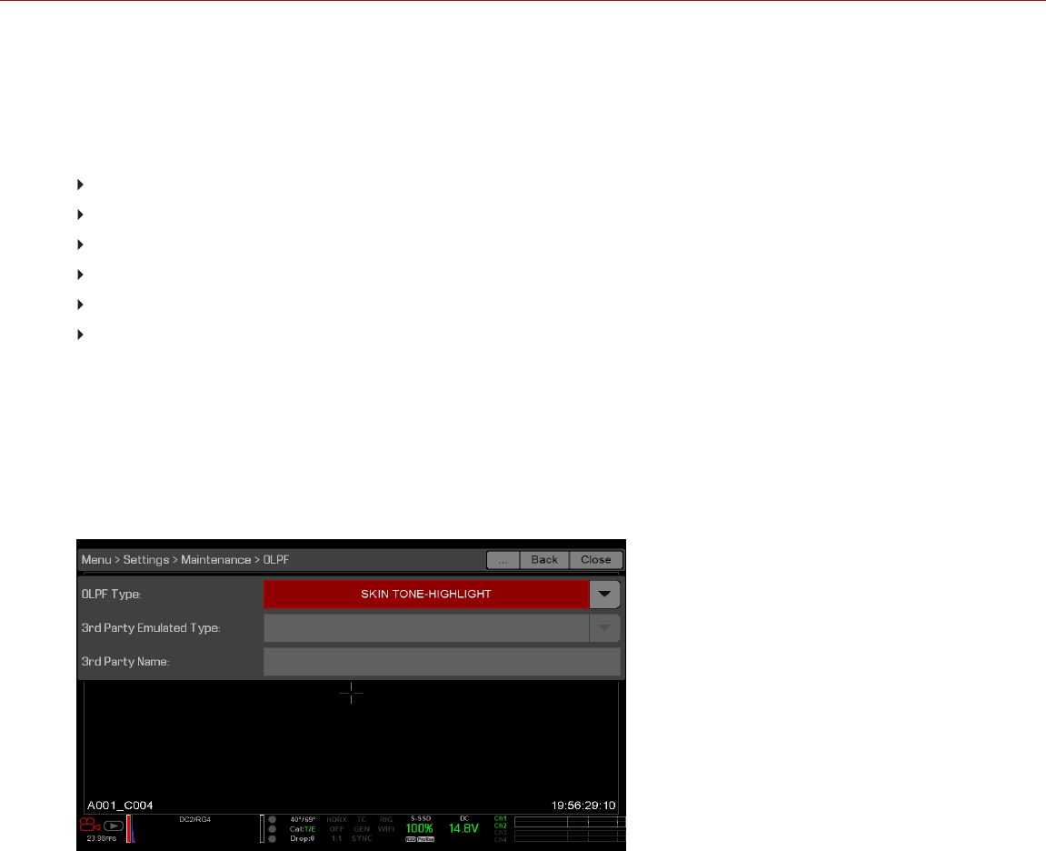
RCP CONNECTIONS
Lists any RCP clients the camera is connected to.
CAMERA INFO
Displays the following camera information:
Type: Camera type and sensor type.
Firmware Version: Current firmware version.
PIN: The personal identification number that is specific to your camera.
SVN Revision: The current firmware number.
Runtime: The number of hours that the camera has been turned on.
Name: Sensor type.
OLPF
RED offers multiple optical low-pass filters (OLPFs). Each OLPF optimizes certain characteristics to take full advantage
and control of each shooting environment. The camera checks the OLPF type, and adjusts the color science based on
the selected OLPF.
To view your OLPF type, go to Menu > Settings > Maintenance > OLPF. The OLPF that is installed in your camera
displays in the OLPF Type field.
Figure: OLPF Menu
C OPYR I GHT © 2 01 9 R ED. C OM , LLC 955- 0159_V 7. 1, R EV -G | 157
EPIC-W GEMINI OPERATION GUIDE

THIRD-PARTY OLPFS
WARNING: RED does not guarantee that third-party OLPFs will work as intended. Any damage caused by using a
third-party OLPF, or any undesirable effects to the footage caused by using a third-party OLPF, is not covered under
any RED warranty. If you have any questions or support issues with a third-party OLPF, contact the OLPF’s
manufacturer.
If you are using a third-party OLPF, follow the instructions below to set up the OLPF:
1. Install the OLPF. For more information, go to "Swap an Interchangeable OLPF" on page53.
2. Go to Menu > Settings > Maintenance > OLPF.
3. Select an option from the 3rd Party Emulated Type drop-down menu. This menu lists the RED OLPFs that are
available for the camera. The camera will simulate the color science based on the RED OLPF that you select. RED
DOES NOT guarantee that the third-party OLPF and the camera’s color science will match.
4. Enter a name for the OLPF in the 3rd Party Name field. The name that you enter is for metadata purposes; the
name has no effect on the color science.
C OPYR I GHT © 2 01 9 R ED. C OM , LLC 955- 0159_V 7. 1, R EV -G | 158
EPIC-W GEMINI OPERATION GUIDE

C OPYR I GHT © 2 01 9 R ED. C OM , LLC 9 55 -0 15 9_V 7. 1, R EV- G|159
EPIC-W GEMINI OPERATION GUIDE
CHAPTER 6:
SENSOR CALIBRATION
Sensor calibration, also known as black shading, is a process during which the camera optimizes image quality by
ensuring that pixel sensitivity remains consistent throughout the sensor. Calibrating the sensor generates a calibration
map based on system and environment settings. After calibration, the sensor shows a uniform noise profile over the
whole area without any falloffs on any side.
The camera offers two (2) ways to calibrate the sensor:
Manual Calibration: RED recommends using Manual Calibration for the HELIUM 8K S35, MONSTRO 8K VV, and
GEMINI 5K S35 sensors. For more information, go to "Calibrate Sensor: Manual Calibration" on the next page.
Auto Calibration: RED recommends using Auto Calibration for the DRAGON 4.5K, DRAGON 5K, DRAGON 6K,
and DRAGON-X 5K sensors. For more information, go to "Calibrate Sensor: Auto Calibration" on page162.
For more information, see the Sensor Calibration Methods article.
NOTE: Calibration maps are still available after performing a system restore.
CHECK NOISE PROFILE
To check the current noise profile, follow the instructions below:
1. Ensure that the camera reaches the temperature you want to use for your shoot.
2. Set the exposure to the exposure you want to use for your shoot.
3. Put a lens cap on the lens (if a lens is attached) or a front body cap on the camera (if a lens is not attached).
4. Set FLUT or Exposure Adjust to 8.000. For more information, go to "ISO Menu " on page86.
5. Check the noise that displays on the monitor:
The noise is random, with no fixed patterns or lines. The sensor is calibrated.
The noise has patterns or lines. Calibrate the sensor.
WHEN TO CALIBRATE SENSOR
Calibration is required:
After an extreme change in temperature (+/– 30°F or +/–15°C) from the current calibration map.
After an extreme change in exposure time (+/– 1/2 sec) from the current calibration map.
If either the T or E in the CAL: T/E indicator is not green.
If the noise profile shows patterns or lines. For more information, go to "Check Noise Profile" above.
After each firmware upgrade.
To check the temperature/exposure of the current calibration file, go to Menu > Settings > Maintenance > System
Status > Project Status.
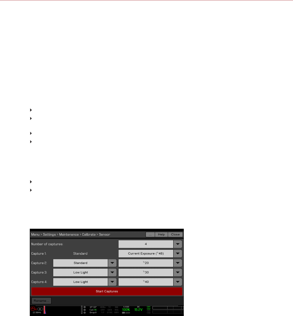
CALIBRATE SENSOR: MANUAL CALIBRATION
The camera offers two (2) ways to calibrate the sensor: Manual Calibration and Auto Calibration. This section
describes how to calibrate the sensor with Manual Calibration.
When you start a Manual Calibration, the camera calibrates the sensor at the current exposure and temperature setting.
You will need to re-calibrate the sensor after extreme changes in exposure and temperature. The Manual Calibration
process takes several minutes.
MANUAL CALIBRATION PROCEDURE
To perform a Manual Calibration, follow the instructions below:
1. Ensure that the camera reaches the temperature that you want to use for your shoot.
2. Set the exposure to the exposure that you want to use for your shoot.
3. Ensure that the sensor is as dark as possible.
Preferably, take off the lens, and install the front body cap.
If you cannot take off the lens, put a lens cap on the lens. (Not all lens caps completely block IR. Lens caps are
made to protect the lens, not necessarily to block light.)
If possible, use a dark room.
Just closing the aperture is NOT sufficient.
4. Go to Menu > Settings > Maintenance > Calibrate > Sensor > Create > Manual.
5. Select how many calibration maps that you want to create from the Number of captures drop-down menu. You
can create up to four (4) calibration maps at a time.
6. Select which Sensor Sensitivity you want to use for each calibration map from the drop-down:
Standard
Low Light
NOTE: Capture 1 uses the Sensor Sensitivity that is currently applied to the camera. To change the Sensor
Sensitivity, go to "Sensor Sensitivity" on page86.
7. Select the exposure that you want for each calibration map from the Capture drop-down menus.
8. Select Start Capture(s).
Figure: Manual Capture Settings
C OPYR I GHT © 2 01 9 R ED. C OM , LLC 955- 0159_V 7. 1, R EV -G | 160
EPIC-W GEMINI OPERATION GUIDE

9. Select OK on the dialog box that opens. The system initializes and then makes multiple passes through the
following phases of the calibration:
Capturing
Analyzing
Erasing
Programming
10. When the Calibration Successful dialog displays, select OK to complete the process.
The new calibration map is automatically selected.
C OPYR I GHT © 2 01 9 R ED. C OM , LLC 955- 0159_V 7. 1, R EV -G | 161
EPIC-W GEMINI OPERATION GUIDE
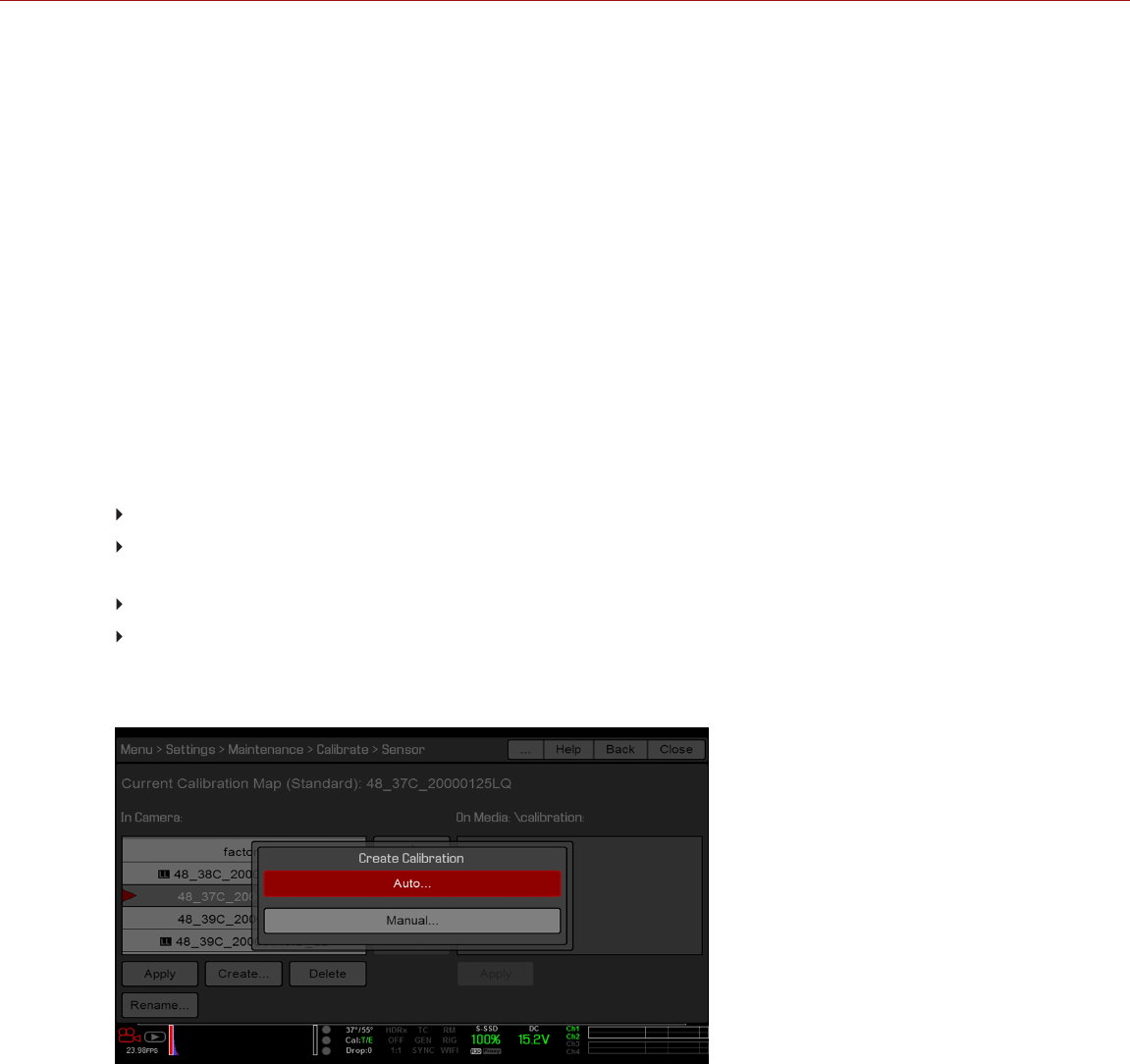
CALIBRATE SENSOR: AUTO CALIBRATION
NOTE: The camera cannot export calibration maps created by Auto Calibration.
The camera offers two (2) ways to calibrate the sensor: Manual Calibration and Auto Calibration. This section
describes how to calibrate the sensor with Auto Calibration.
When you start an Auto Calibration, the camera calibrates the sensor at 16 exposure settings, and uses that data to
build a calibration curve. Afterward, the sensor is calibrated for each exposure along the calibration curve, so you do
not need to re-calibrate every time you change the exposure.
The calibration process does not factor in multiple temperatures, so you will need to re-calibrate the sensor after
extreme changes in temperature.
This process can take up to 1 hour.
AUTO CALIBRATION PROCEDURE
To perform an Auto Calibration, follow the instructions below:
1. Ensure that the camera reaches the temperature that you want to use for your shoot.
2. Ensure that the sensor is as dark as possible.
Preferably, take off the lens, and install the front body cap.
If you cannot take off the lens, put a lens cap on the lens. (Not all lens caps completely block IR. Lens caps are
made to protect the lens, not necessarily to block light.)
If possible, use a dark room.
Just closing the aperture is NOT sufficient.
3. Ensure a properly formatted SSD is attached to the camera.
4. Go to Menu > Settings > Maintenance > Calibrate > Sensor > Create > Auto.
Figure: Select Auto
C OPYR I GHT © 2 01 9 R ED. C OM , LLC 955- 0159_V 7. 1, R EV -G | 162
EPIC-W GEMINI OPERATION GUIDE
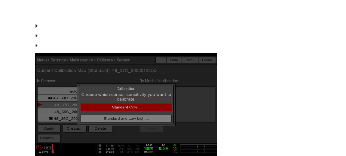
5. Select which Sensor Sensitivity you want to calibrate at:
Low Light Only: This option displays when the current Sensor Sensitivity is Low Light.
Standard Only: This option displays when the current Sensor Sensitivity is Standard.
Standard and Low Light: This option always displays.
Figure: Select Sensor Sensitivity for Auto Calibration
6. Select OK on the dialog box that opens. The system initializes and then makes multiple passes through the
calibration phases.
7. When the Calibration Successful dialog displays, select OK to complete the process.
NOTE: When you change the exposure setting, the E indicator turns yellow and it may take up to 8 seconds for the
calibration map to load.
C OPYR I GHT © 2 01 9 R ED. C OM , LLC 955- 0159_V 7. 1, R EV -G | 163
EPIC-W GEMINI OPERATION GUIDE
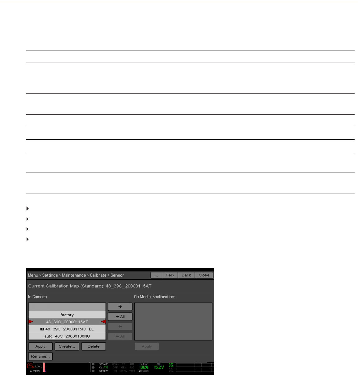
CALIBRATION MAP NAMING CONVENTIONS
All calibration maps for Low Light Sensor Sensitivity are marked with the "LL" symbol.
Each calibration map has a unique name that uses the format described in the table below:
NAME DESCRIPTION EXAMPLE
Exposure Current exposure; to set exposure, go to "Exposure/Shutter" on page118
If the calibration map was created using Auto Calibration, then "auto" displays instead
of an exposure setting
48
auto
Sensor
Temperature
Sensor temperature (Celsius); in the Lower Status Row, this is the number to the left of
the forward slash (Temp: 32/35)
32C
Year Year that the calibration map is created (yyyy) 2014
Month Month that the calibration map is created (mm) 01
Day Day that the calibration map is created (dd) 28
Letters Two random alphanumeric characters generated by the camera to prevent any
possibility of duplicate names being created
LQ
Low Light
Indicator
All calibration maps for Low Light Sensor Sensitivity have the suffix "_LL" LL
For example, a set of calibration maps may look like this:
48_39C_20000115AT
48_39C_20000115ID_LL
auto_40C_20000108NU
48_38C_200001257A_LL
NOTE: If you mount an SSD with calibration files to your computer, each calibration map displays as a sub-folder in a
folder called Calibration. To save a calibration map to your hard drive, copy the entire sub-folder to your drive.
Figure: Sensor Calibration Menu
C OPYR I GHT © 2 01 9 R ED. C OM , LLC 955- 0159_V 7. 1, R EV -G | 164
EPIC-W GEMINI OPERATION GUIDE

CALIBRATION MANAGEMENT
To apply, export, and import calibration maps, go to Menu > Settings > Maintenance > Calibrate > Sensor.
In Camera: The calibration maps that are saved internally on the camera:
Factory: This is the calibration map generated during the manufacturing process. (Default)
All other: The user-created calibration maps.
Media: The calibration maps that are on the SSD in the path shown (for example, S-SSD\calibration).
CALIBRATION MAP ACTIONS
NOTE: You cannot delete or rename the factory map.
Apply: Apply the selected calibration map (if the calibration map is on the SSD, the camera applies the map
temporarily, and does not import it into the camera). You can only apply a calibration map for the current Sensor
Sensitivity. For example, if a Low Light ISO is selected, you can only apply a calibration map created with Low
Light. For more information on Sensor Sensitivity, go to "Sensor Sensitivity" on page86.
Create: Create a calibration map. For more information, go to "Calibrate Sensor: Manual Calibration" on page160
and "Calibrate Sensor: Auto Calibration" on page162.
Delete: Delete the selected camera calibration map.
Rename: Rename the selected calibration map.
EXPORT AND IMPORT CALIBRATION MAPS
NOTE: The camera cannot export calibration maps created by Auto Calibration.
Calibration maps can be stored on the camera or transferred to SSD. You can also build a library of calibration maps
to use in different settings. A camera only imports calibration maps that it created. Calibration maps cannot be shared
between cameras.
: Export selected calibration map from camera to SSD.
All: Export all files from camera to SSD.
: Import selected calibration map from SSD to camera. This overwrites the user HS calibration map.
All: Import all files from SSD to camera.
C OPYR I GHT © 2 01 9 R ED. C OM , LLC 955- 0159_V 7. 1, R EV -G | 165
EPIC-W GEMINI OPERATION GUIDE

C OPYR I GHT © 2 01 9 R ED. C OM , LLC 9 55 -0 15 9_V 7. 1, R EV- G|166
EPIC-W GEMINI OPERATION GUIDE
CHAPTER 7:
AUDIO SYSTEM
AUDIO OVERVIEW
The BRAIN has two (2) integrated dual channel digital stereo microphones that record uncompressed audio at 24-bit
48 kHz. These microphones offer you the ability to capture scratch-track audio.
The DSMC2 Base Expander, DSMC2 V-Lock I/O Expander, DSMC2 REDVOLT Expander, and DSMC2 Production
Module each feature a built-in headphone jack, so you can hear the audio during playback via headphones. Together,
the integrated microphones and headphone jack offer an audio solution for run-and-gun shoots.
Additional audio input/output options are determined by the attached expander or module. For the highest level of
professional audio recording, RED recommends using the DSMC2 REDVOLT Expander or DSMC2 Production
Module, which feature two (2) full-size XLR audio jacks.
The camera can record up to four (4) discrete stereo channels of uncompressed 24-bit, 48 kHz audio.
Input signals are routed via a high-quality pre-amplifier to achieve the desired recording levels and maximize dynamic
range.
Audio data is synchronized with video and timecode and embedded in the R3D® file. You can export audio data from
REDCINE-X PRO® as separate audio files.
Audio is also embedded in any HD-SDI and HDMI® output connected to the camera (except the MON-1 signal).
NOTE: If using a third-party module, some audio controls may not be available in-camera.
SET UP AUDIO
To set up audio, go to Menu > Settings > Audio. To adjust the input, pre-amplifier, and headphone settings, select
Control. To adjust the mix settings, select Mix.
Figure: Audio Menu
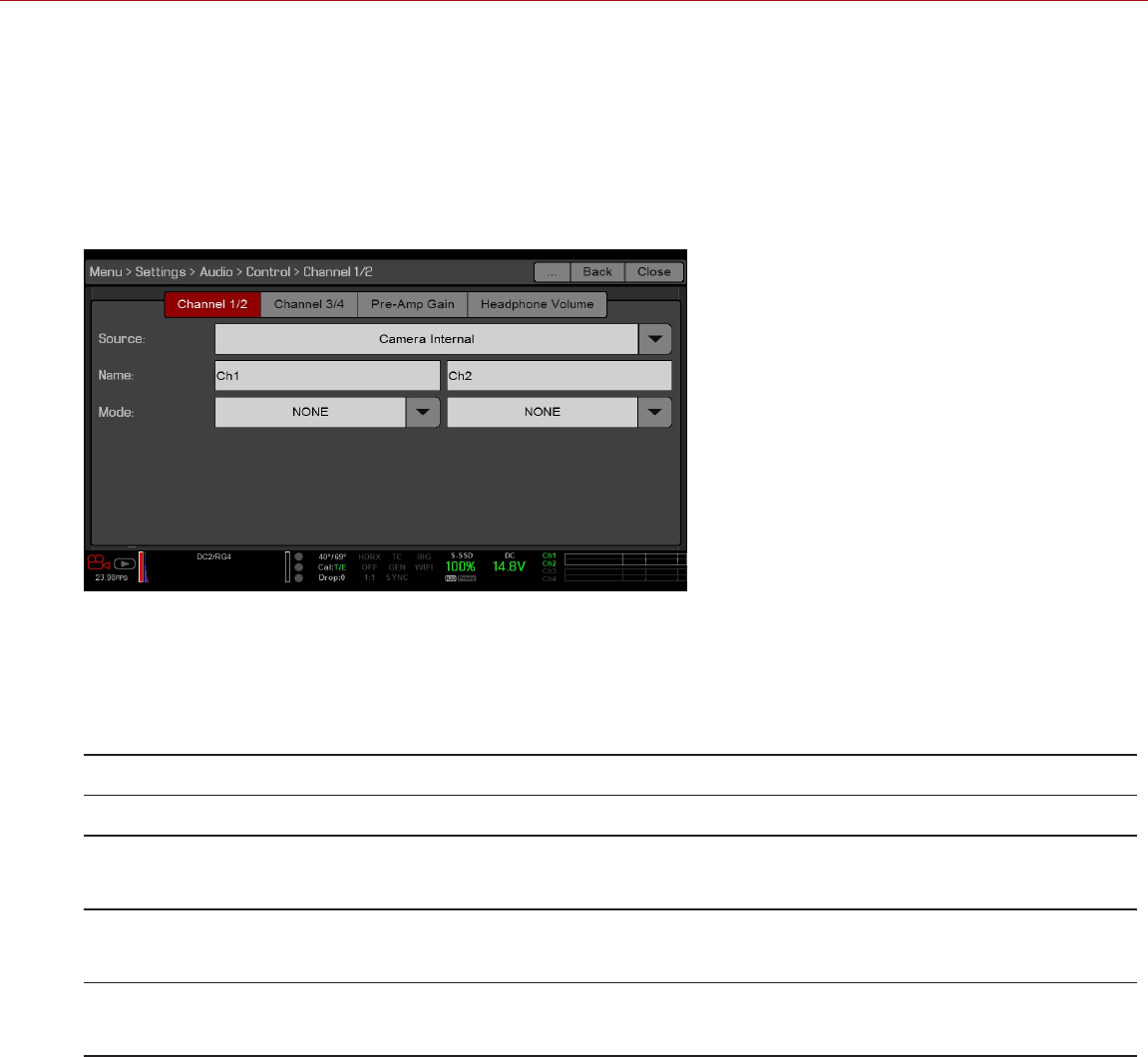
CONTROL
NOTE: If using a third-party module, some audio controls may not be available in-camera.
To adjust the input, pre-amplifier, and headphone settings, select Control.
CHANNEL 1/2 AND CHANNEL 3/4
To set up Channel 1/2 and 3/4, go to Menu > Settings > Audio > Control.
Figure: Channel Setup
SOURCE
The audio source options only display when the expanders are attached.
SOURCE NAME CHANNEL PAIRS DEVICE CONNECTORS
None N/A N/A N/A
Camera Internal Ch1/Ch2, Ch3/Ch4 DSMC BRAIN Mic 1 (Ch1 and Ch3)
Mic 2 (Ch2 and Ch4)
Rear Analog Ch1/Ch2, Ch3/Ch4 DSMC2 Base Expander
DSMC2 V-Lock I/O Expander
Stereo Microphone
Rear Analog Ch1/Ch2, Ch3/Ch4 DSMC2 REDVOLT Expander
DSMC2 Production Module
AUDIO 1 and AUDIO 2 (full-size XLR)
NAME
You can rename each audio channel. The default names are Ch1, Ch2, Ch3, and Ch4. The channel names display in
the Audio Meter, but are not included in the clip metadata.
MODE
When Rear Analog is selected, the Mode (Line, Mic, or +48V) displays for the incoming audio signal.
C OPYR I GHT © 2 01 9 R ED. C OM , LLC 955- 0159_V 7. 1, R EV -G | 167
EPIC-W GEMINI OPERATION GUIDE
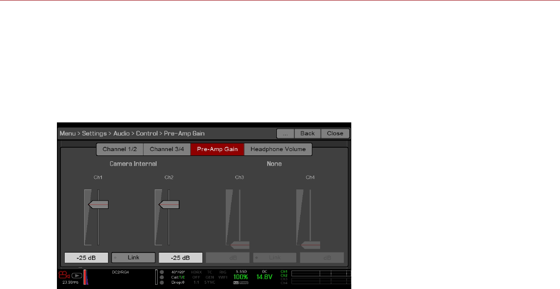
PRE-AMP GAIN
The range and default depends on the attached expander.
To adjust amplification levels, follow the instructions below:
1. Go to Menu > Settings > Audio > Control > Pre-Amp Gain.
2. Move the Pre-Amp (pre-amplifier) sliders up and down to adjust the amplification levels.
3. To link the amplification for each channel, select Link.
Figure: Pre-Amp Gain
C OPYR I GHT © 2 01 9 R ED. C OM , LLC 955- 0159_V 7. 1, R EV -G | 168
EPIC-W GEMINI OPERATION GUIDE
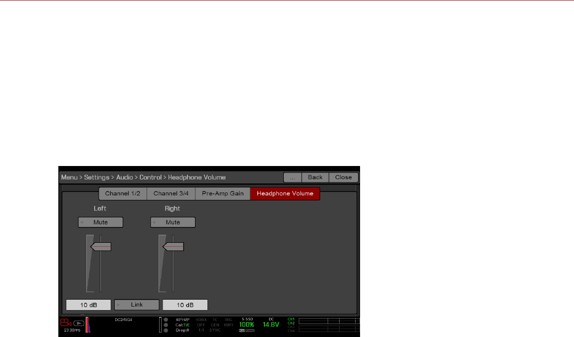
HEADPHONE VOLUME
The range and default depends on the attached expander.
CHANGE HEADPHONE VOLUME
1. Go to Menu > Settings > Audio > Control > Headphone Volume.
2. Move the Left and Right sliders up and down to adjust the volume.
3. To toggle mute/unmute, select Mute. (Applicable to DSMC2 Base Expander and DSMC2 V-Lock I/O Expander
only.)
4. To link the volume for Left and Right, select Link.
Figure: Headphone Volume
C OPYR I GHT © 2 01 9 R ED. C OM , LLC 955- 0159_V 7. 1, R EV -G | 169
EPIC-W GEMINI OPERATION GUIDE
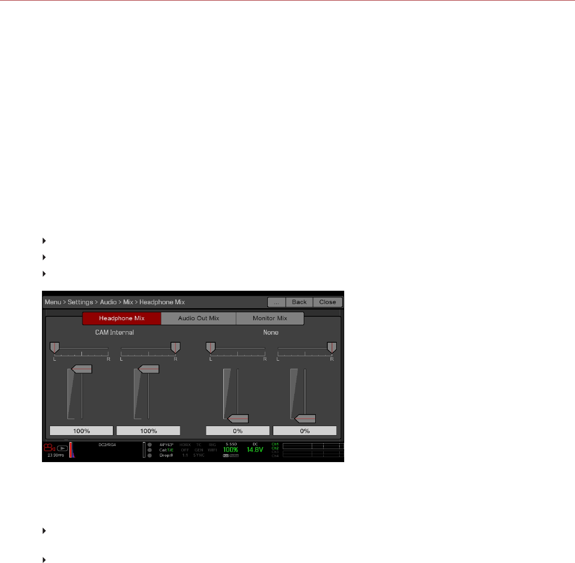
MIX
NOTE: If using a third-party module, some audio controls may not be available in-camera.
NOTE: For DSMC2 Jetpack Expander and DSMC2 Jetpack-SDI Expander, the only available option is Monitor Mix.
The camera features a digital audio mixer that controls the volume and stereo settings for each input channel. The
mixer affects audio monitoring (such as headphones) and audio recorded to external devices. The mixer DOES NOT
affect audio embedded in the R3D file. To access mix settings, go to Menu > Settings > Audio > Mix.
The range for each channel is 0% to 100%. The default for each active channel is 100%. Channel 3 and Channel 4 are
active only when there is audio input.
The digital mixer normalizes each output to prevent the output from exceeding the signal range. For example, if you
pass Channel 1 to an output at 100%, and then mix Channel 2 into the same output, the level of Channel 1 decreases
to 50%.
Assign each audio channel to the Left, Middle, or Right side of the stereo mix. Move the sliders up and down to
adjust the volume.
You can control the volume and stereo for each audio monitoring option:
Headphone Mix: Headphones plugged into the camera.
Audio Out Mix: Line out plugged into an expander or module. The input gain is fixed.
Monitor Mix: External HDMI and HD-SDI monitors that support audio.
Figure: Mix
AUDIO OUTPUT OPTIONS
DSMC2 Base Expander, DSMC2 V-Lock I/O Expander, DSMC2 REDVOLT Expander, DSMC2 Production
Module: One (1) 2-channel headphone output. For maximum quality, use high impedance headphones.
HDMI and HD-SDI monitor: Both output two (2) channels of 24-bit 48 kHz uncompressed, embedded digital
audio. Select and mix the stereo channels in the Monitor Mix menu at Menu > Settings > Audio > Mix > Monitor
Mix. To monitor audio via HDMI or HD-SDI, the third-party monitor must support audio.
AUDIO METER (VU METER)
The Audio Meter displays at the bottom-right corner of the viewfinder, and displays either the incoming audio channels
(default), or the outgoing audio (mixes). For more information, go to "VU Meter" on page101.
C OPYR I GHT © 2 01 9 R ED. C OM , LLC 955- 0159_V 7. 1, R EV -G | 170
EPIC-W GEMINI OPERATION GUIDE

INCOMING AUDIO CHANNELS
When you select Input as the VU Meter Source, the Audio Meter displays the incoming audio channels (default). For
more information, go to "VU Meter" on page101. Channel 1 and Channel 2 are the default channels, correlating with
the MIC-1 and MIC-2 inputs on the camera. Channel 3 and Channel 4 are greyed out unless the camera detects audio
input.
The channel names selected in the Audio menu determine the channel names displayed in the Audio Meter.
The Audio Meter shows the incoming audio signal when a source is selected, even if the channel is not recorded.
When a channel is recorded, the channel indicator left of the Audio Meter is green.
OUTGOING AUDIO
When you select Output as the VU Meter Source, the Audio Meter displays the Headphone Mix, Audio Out Mix, and
Monitor Mix levels. For more information, go to "VU Meter" on page101.
When recording to an external device, use the Output levels to help accurately monitor recorded audio.
AUDIO METER LEVELS
Figure: Audio Meter
The camera updates the Audio Meter 12 times per second with the maximum signal from the last 1/12 of a second
period. The range of the Audio Meter is –52 dBFS to 0 dBFS.
The lines and colors indicate danger of clipping, as described in the table below:
LINE DBFS COLOR DESCRIPTION
First line (far left border; solid) –52 dBFS Green Audio is not clipping
Second line (solid) –20 dBFS Green Audio is not clipping
Third line (dashed) –12 dBFS Yellow Audio close to clipping
Fourth line (dashed) –2 dBFS Red Audio is clipping
Fifth line (far right border;
solid)
0 dBFS Red Audio is clipping (if signal exceeds –1 dBFS, the whole bar is
red)
NOTE: In the American broadcast and post production systems, –20 dBFS roughly corresponds to 0 VU and 4 dBu. In
a digital system, dBu is an approximation; the correct unit for digital audio levels is dBFS.
AUDIO DURING PLAYBACK
The camera plays all recorded channels during playback (via headphones or HDMI and HD-SDI monitors), and
automatically unmutes any muted audio outputs.
To access audio settings during playback, go to Menu > Settings > Audio and select the following tabs:
Control
Mix
C OPYR I GHT © 2 01 9 R ED. C OM , LLC 955- 0159_V 7. 1, R EV -G | 171
EPIC-W GEMINI OPERATION GUIDE
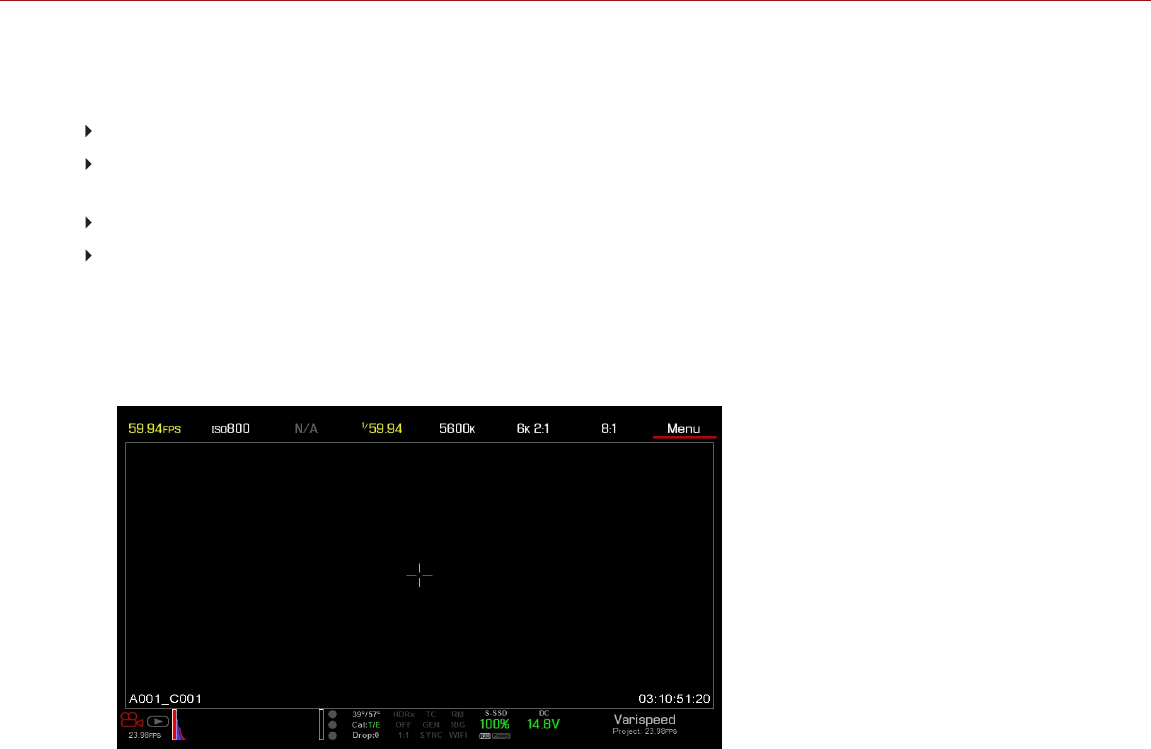
RECORD AUDIO IN VARISPEED MODE
The camera supports recording audio in Varispeed mode when all of the following criteria is met:
The Recording Frame Rate is higher than the Project Time Base
The Recording Storage is set to Local, and the Recording mode is set to Continuous Record (Menu > Settings >
Recording > Mode)
The Record varispeed audio in a separate WAV file check box is selected (Menu > Settings > Recording > Mode)
The Record File Format includes R3D (Menu > Settings > Recording > Codec)
To record audio in Varispeed mode, follow the instructions below:
1. Set the Recording Frame Rate to a higher rate than the Project Time Base. The camera cannot record audio when
the Recording Frame Rate is lower than the Project Time Base. For more information, go to "Frame Rate" on
page117.
Figure: Enable Varispeed
2. Go to Menu > Settings > Recording > Mode.
3. Select Local from the Storage drop-down menu.
4. Select Continuous Record from the Mode drop-down menu.
C OPYR I GHT © 2 01 9 R ED. C OM , LLC 955- 0159_V 7. 1, R EV -G | 172
EPIC-W GEMINI OPERATION GUIDE
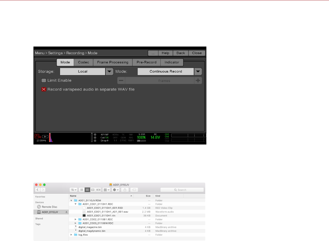
5. Select the Record varispeed audio in a separate WAV file check box. This option is available only when the
Recording Frame Rate is higher than the Project Time Base.
The Audio Meters display in the Lower Status Row. For more information, go to "Audio Meter (VU Meter)" on
page170.
Figure: Record Varispeed Audio
6. Record.
7. When you mount the SSD to a computer, a WAV file displays in the RDC folder.
Figure: WAV File in RDC Folder
C OPYR I GHT © 2 01 9 R ED. C OM , LLC 955- 0159_V 7. 1, R EV -G | 173
EPIC-W GEMINI OPERATION GUIDE

C OPYR I GHT © 2 01 9 R ED. C OM , LLC 9 55 -0 15 9_V 7. 1, R EV- G|174
EPIC-W GEMINI OPERATION GUIDE
CHAPTER 8:
TIMECODE, GENLOCK, MULTI-
CAMERA SETUP
This chapter describes timecode, genlock, and multi-camera operations such as 3D and array setup.
NOTE: These configurations require specific expanders or modules. For more information, go to "Input/Output
Connectors" on page219.
TIMECODE
Timecode is a numeric sequence based on SMPTE 12M that aids in the management and synchronization of footage
and audio. Timecode is embedded in recorded RAW files, QuickTime® files (if recording an Apple® ProRes codec),
and MXF files (if recording an Avid® codec) as metadata and in HANC metadata provided by the HD-SDI monitor
output. The camera can generate timecode on its own or can receive and sync to timecode generated by an external
source. RED cameras use non-drop frame timecode.
Timecode displays in the lower right corner of the Live Action Area on the graphical user interface (GUI) and is
embedded as metadata. Timecode is represented as an eight (8) digit sequence (HH:MM:SS:FF), where:
HH: Hours
MM: Minutes
SS: Seconds
FF: Frames
NOTE: Timecode is most accurate and effective when coupled with genlock. For more information, go to "Genlock"
on page177.
NOTE: For more information on HANC metadata, see HD- SDI HANC Metadata Information , available at
www.red.com/developers.
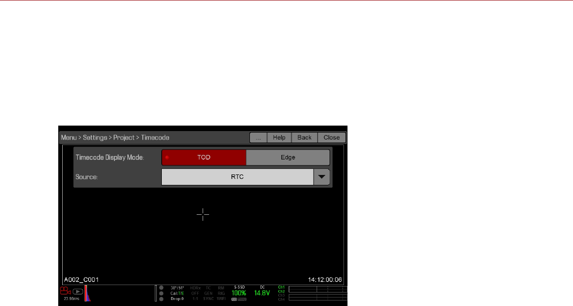
SET UP INTERNAL TIMECODE
To set up and adjust timecode generated by the camera, follow the instructions below:
1. Go to Menu > Settings > Project > Timecode.
2. Select the desired Timecode Display mode.
3. Set Source to RTC.
The TC indicator in the Lower Status Row remains grey when internal timecode is enabled.
Figure: Timecode
OUTPUT TIMECODE
NOTE: Outputting timecode from the camera requires a DSMC2 REDVOLT Expander or DSMC2 Production Module.
To output a timecode signal to an external device or slaved camera, follow the instructions below:
1. Follow the instructions in "Set Up Internal Timecode" above to set up internal timecode.
2. Connect the camera to another device using the PRO I/O TIMECODE CABLE (3').
A. Connect one connector to the TIMECODE port on the expander or module.
B. Connect the other connector to an external device or camera.
REQUIRED CABLE
790-0212: PRO I/O TIMECODE CABLE (3')
C OPYR I GHT © 2 01 9 R ED. C OM , LLC 955- 0159_V 7. 1, R EV -G | 175
EPIC-W GEMINI OPERATION GUIDE
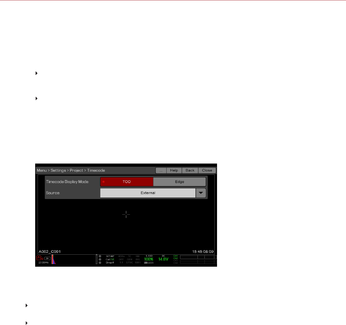
INPUT EXTERNAL TIMECODE
NOTE: This procedure requires a DSMC2 Base Expander, DSMC2 V-Lock I/O Expander, DSMC2 Jetpack Expander,
DSMC2 Jetpack-SDI Expander, DSMC2 REDVOLT Expander, or DSMC2 Production Module. For more information,
go to "Input/Output Connectors" on page219.
To input timecode generated by an external device, follow the instructions below:
1. Connect the external timecode generator to the camera:
DSMC2 Base Expander, DSMC2 V-Lock I/O Expander, DSMC2 Jetpack Expander, or DSMC2 Jetpack-
SDI Expander: Connect the SYNC port (4-Pin 00B) on the expander to the device (yellow BNC) using a 3BNC-
to-00 Sync Cable.
DSMC2 REDVOLT Expander or DSMC2 Production Module: Connect the TIMECODE port on the expander
or module to the device using a 75 ohm BNC cable.
2. Go to Menu > Settings > Project > Timecode.
3. Select the desired Timecode Display Mode.
4. Set Source to External.
The TC indicator in the Lower Status Row turns green when an external timecode source is locked.
NOTE: When an external source is selected but not present, timecode displays User Provided settings.
Figure: Source: External
REQUIRED CABLE
DSMC2 Base Expander, DSMC2 V-Lock I/O Expander, DSMC2 Jetpack Expander, or DSMC2 Jetpack-SDI
Expander: 790-0154, 790-0643, 3BNC-to-00
DSMC2 REDVOLT Expander or DSMC2 Production Module: 790-0212, PRO I/O TIMECODE CABLE (3')
C OPYR I GHT © 2 01 9 R ED. C OM , LLC 955- 0159_V 7. 1, R EV -G | 176
EPIC-W GEMINI OPERATION GUIDE

GENLOCK
Generator locking (genlock) is a tri-level signal used to synchronize video and audio systems. Genlock is based on
SMPTE 296M and 274M. There are two (2) important genlock sync modes:
Monitor Sync
Sensor Sync
MONITOR SYNC
NOTE: Using genlock requires a DSMC2 Base Expander, DSMC2 V-Lock I/O Expander, DSMC2 Jetpack Expander,
DSMC2 Jetpack-SDI Expander, DSMC2 REDVOLT Expander, or DSMC2 Production Module. For more information,
go to "Input/Output Connectors" on page219.
Monitor Sync occurs when an incoming genlock signal is compatible with the monitor output frequency. Monitor Sync
is achievable even if the camera is using another form of synchronization to sync the camera sensor.
1. Connect the genlock device to the camera:
DSMC2 Base Expander, DSMC2 V-Lock I/O Expander, DSMC2 Jetpack Expander, or DSMC2 Jetpack-
SDI Expander: Connect the SYNC port (00B) on the expander to the device (green BNC) using a 3BNC-to-00
Sync Cable.
DSMC2 REDVOLT Expander or DSMC2 Production Module: Connect the GENLOCK port on the expander
or module to the device using a 75 ohm BNC cable.
2. Set up the frequency for the HD-SDI output (select Auto to automatically match the HD-SDI output to the current
Project Time Base). For more information, go to "Frequency" on page91.
Monitor Sync is achieved automatically when an incoming genlock signal is compatible with the monitor output
frequency. When Monitor Sync is achieved, the GEN indicator in the Lower Status Row illuminates green.
REQUIRED CABLE
DSMC2 Base Expander, DSMC2 V-Lock I/O Expander, DSMC2 Jetpack Expander, or DSMC2 Jetpack-SDI
Expander: 790-0154, 790-0643, 3BNC-to-00
DSMC2 REDVOLT Expander or DSMC2 Production Module: 75 ohm BNC cable (such as the RED HD-SDI
Cable, P/N 790-0341)
C OPYR I GHT © 2 01 9 R ED. C OM , LLC 955- 0159_V 7. 1, R EV -G | 177
EPIC-W GEMINI OPERATION GUIDE

SENSOR SYNC
NOTE: HDRX® is not available when Genlock Sensor Sync is enabled.
Sensor Sync is achieved when an incoming genlock signal is compatible with the monitor output frequency, project
time base, and recording frame rate. In Sensor Sync mode, sensor timing is locked to the genlock signal. Sensor
Sync requires the following synchronized settings:
SETTING MENU LOCATION PATH
Genlock signal frequency N/A; external genlock device
HD-SDI monitor output frequency Menu > Monitoring > Monitors > select monitor
Project Time Base Menu > Settings > Project > Frame Rate
Recording Frame Rate Menu > Settings > Project > Frame Rate
SET UP SENSOR SYNC MODE
NOTE: Using genlock requires a DSMC2 Base Expander, DSMC2 V-Lock I/O Expander, DSMC2 Jetpack Expander,
DSMC2 Jetpack-SDI Expander, DSMC2 REDVOLT Expander, or DSMC2 Production Module. For more information,
go to "Input/Output Connectors" on page219.
To set up and enable Sensor Sync Mode, follow the instructions below:
1. Ensure that the Project Time Base and Recording Frame Rate will be compatible with the incoming genlock signal.
2. Connect the genlock device to the camera:
DSMC2 Base Expander, DSMC2 V-Lock I/O Expander, DSMC2 Jetpack Expander, or DSMC2 Jetpack-
SDI Expander: Connect the SYNC port (00B) on the expander to the device (green BNC) using a 3BNC-to-00
Sync Cable.
DSMC2 REDVOLT Expander or DSMC2 Production Module: Connect the GENLOCK port on the expander
or module to the device using a 75 ohm BNC cable.
3. Go to Menu > Settings > Setup > GPIO/Sync > Sync.
4. Select Genlock from the Sensor Sync Mode drop-down menu.
5. Set up the frequency for the HD-SDI output (select Auto to automatically match the HD-SDI output to the current
Project Time Base). For more information, go to "Frequency" on page91.
The GEN indicator in the Lower Status Row turns green when a compatible genlock signal is present and genlock
is enabled. The SYNC indicator in the Lower Status Row turns green when Sensor Sync is achieved.
REQUIRED CABLE
DSMC2 Base Expander, DSMC2 V-Lock I/O Expander, DSMC2 Jetpack Expander, or DSMC2 Jetpack-SDI
Expander: 790-0154, 790-0643, 3BNC-to-00
DSMC2 REDVOLT Expander or DSMC2 Production Module: 75 ohm BNC cable (such as the RED HD-SDI
Cable, P/N 790-0341)
C OPYR I GHT © 2 01 9 R ED. C OM , LLC 955- 0159_V 7. 1, R EV -G | 178
EPIC-W GEMINI OPERATION GUIDE

MASTER/SLAVE OPERATION
NOTE: Master/Slave operation, including stereo/3D and camera arrays, requires a GIG-E port, which is available on the
DSMC2 Jetpack-SDI Expander, DSMC2 REDVOLT Expander, and DSMC2 Production Module. For more information,
go to "GIG-E (Ethernet)" on page238.
NOTE: The Master camera controls metadata and basic camera parameters of the Slave cameras. Any other setting
changes required by the Slave cameras must be made before recording.
This section describes operation in Master/Slave configuration and clip naming conventions for clips recorded on
those cameras. Master/Slave is the most common configuration for Stereo/3D productions.
When cameras are operated in Master/Slave configuration, you can perform the following operations:
Power: Turn off the Master camera to turn off both cameras.
Record: Press the PWR/REC key on the Master camera to start/stop recording on both cameras.
Change settings: Change settings on the Master camera, to change settings on the Slave camera.
For a Master/Slave configuration to function, the cameras must have the same:
Firmware version
Project time base
Recording frame rate
BRAIN
Sensor
C OPYR I GHT © 2 01 9 R ED. C OM , LLC 955- 0159_V 7. 1, R EV -G | 179
EPIC-W GEMINI OPERATION GUIDE
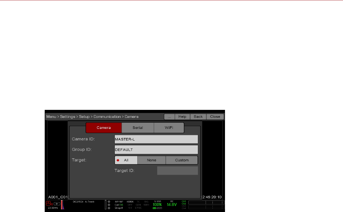
SET UP MASTER/SLAVE OPERATION
NOTE: Master/Slave operation, including stereo/3D and camera arrays, requires a GIG-E port, which is available on the
DSMC2 Jetpack-SDI Expander, DSMC2 REDVOLT Expander, and DSMC2 Production Module. For more information,
go to "GIG-E (Ethernet)" on page238.
1. Connect the cameras using the Master/Slave Gig-E Cable:
A. Connect the GIG-E port on one expander or module to the GIG-E port on the other expander or module.
2. On the Master camera, follow the instructions below:
A. Go to Menu > Settings > Setup > Communication.
B. Type a name for the camera (Example: CAM A, LEFT, MASTER, etc) in the Camera ID field.
C. Set Target to All.
Figure: Master Settings
D. Go to Menu > Settings > Setup > Communication and select the Ethernet tab.
E. Select the Camera to Camera the check box.
C OPYR I GHT © 2 01 9 R ED. C OM , LLC 955- 0159_V 7. 1, R EV -G | 180
EPIC-W GEMINI OPERATION GUIDE
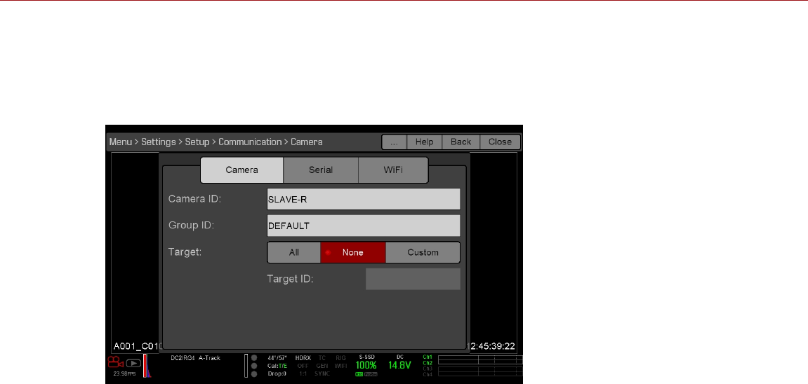
3. On the Slave camera(s), follow the instructions below:
A. Go to Menu > Settings > Setup > Communication.
B. Type a name for the camera (Example: CAM B, RIGHT, SLAVE, etc) in the Camera ID field.
C. Set Target to None.
Figure: Slave Settings
D. Go to Menu > Settings > Setup > Communication and select the Ethernet tab.
E. Select the Camera to Camera check box.
The LAN indicator in the Lower Status Row illuminates green.
NOTE: Cameras can also be set up in a Master/Master configuration. To set up Master/Master, set Target to All
on both cameras, allowing either camera to make changes and control record start/stop.
REQUIRED CABLE
790-0163: Master/Slave Gig-E Cable (4')
C OPYR I GHT © 2 01 9 R ED. C OM , LLC 955- 0159_V 7. 1, R EV -G | 181
EPIC-W GEMINI OPERATION GUIDE
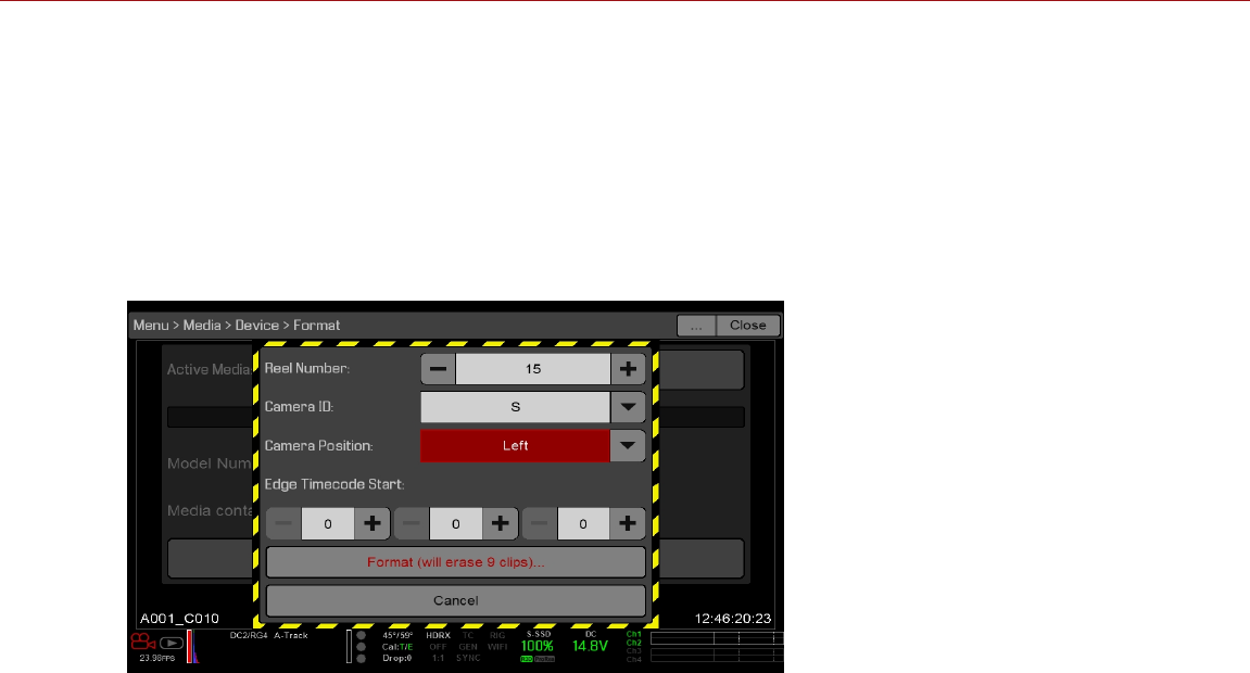
SET REEL NUMBER, CAMERA ID, AND CAMERA POSITION
NOTE: Camera ID and Camera Position settings can also be found at Menu > Settings > Project > Slate > Camera.
To prepare media and slate settings for a Master/Slave or Stereo/3D production, follow the instructions below:
1. On both Master and Slave cameras, go to Menu > Media > Device and select Format Media....
2. On both Master and Slave cameras, select the desired Reel Number and Camera ID settings. The Reel Number
and Camera ID settings on both cameras should match.
3. On the Master camera, change the Camera Position to Left, representing “left eye”.
Figure: Master Settings
4. On the Slave camera, change the Camera Position to Right, representing “right eye”.
5. On both cameras, select Format... to format media and set the Reel Number, Camera ID, and Camera Position
settings.
C OPYR I GHT © 2 01 9 R ED. C OM , LLC 955- 0159_V 7. 1, R EV -G | 182
EPIC-W GEMINI OPERATION GUIDE

MULTI-CAMERA CLIP NAMING CONVENTIONS
This section describes automatic camera-generated clip naming conventions based on slate settings. Cameras use
the Reel No, Cam ID, and Cam Pos settings to generate a custom clip name.
For example, if you have two (2) cameras in Master/Slave configuration and format media on both cameras with the
following settings:
CAMERA REEL NUMBER CAMERA ID CAMERA POSITION
Master 1 S Left
Slave 1 S Right
The first clip recorded by this Master/Slave camera configuration is:
Master: S001_L001_0503B6.R3D
Slave: S001_R001_0503R7.R3D
NOTE: B6 and R7 are examples of camera-generated wildcard characters.
NOTE: If both cameras have a Camera Position of Left, the recorded clips will have the same filename structure, with
the exception of the camera-generated wildcard characters. For example:
Master: A001_C001_0503B6.R3D
Slave: A001_C001_0503R7.R3D
NOTE: Reel Number, Camera ID, and Camera Position can be set when formatting media.
C OPYR I GHT © 2 01 9 R ED. C OM , LLC 955- 0159_V 7. 1, R EV -G | 183
EPIC-W GEMINI OPERATION GUIDE

SET UP STEREO/3D CONFIGURATION
NOTE: Master/Slave operation requires a GIG-E port, which is available on the DSMC2 Jetpack-SDI Expander,
DSMC2 REDVOLT Expander, and DSMC2 Production Module. For more information, go to "GIG-E (Ethernet)" on
page238.
This section describes basic procedures for connecting two (2) cameras in a Master/Slave configuration for 3D
operation.
NOTE: When providing the signals to a Stereo Image Processor (SiP) for verifying 3D alignment, set the HD-SDI
monitor output on both cameras to have the same overlay configuration.
NOTE: For genlock to function correctly, the cameras must be on the same firmware version, and must be using the
same project time base and recording frame rate.
To set up a Stereo/3D setup, follow the instructions below.
1. On both cameras, set the project time base and recording frame rate.
2. On both cameras, follow the instructions in "Sensor Sync" on page178 to achieve Sensor Sync genlock status.
The GEN and SYNC indicators in the Lower Status Row illuminate green.
3. Follow the instructions in "Set Up Master/Slave Operation" on page180 to set Master and Slave camera settings.
4. On both cameras, follow the instructions in "Set Reel Number, Camera ID, and Camera Position" on page182 to
set up media and camera settings.
REQUIRED CABLES
Use one (1) per camera:
75 ohm BNC cable (such as the RED HD-SDI Cable, P/N 790-0341)
Use one (1) per setup:
790-0163: Master/Slave Gig-E Cable (4')
C OPYR I GHT © 2 01 9 R ED. C OM , LLC 955- 0159_V 7. 1, R EV -G | 184
EPIC-W GEMINI OPERATION GUIDE

CAMERA ARRAY
SET UP A CAMERA ARRAY
NOTE: Master/Slave operation, including stereo/3D and camera arrays, requires a GIG-E port, which is available on the
DSMC2 Jetpack-SDI Expander, DSMC2 REDVOLT Expander, and DSMC2 Production Module. For more information,
go to "GIG-E (Ethernet)" on page238.
NOTE: For genlock to function correctly, the cameras must be on the same firmware version, and must be using the
same project time base and recording frame rate.
NOTE: To operate a camera array setup from a Windows ® computer or workstation, you need one of several
applications provided by RED® or third-party developers.
You can sync more than two (2) cameras for applications and productions that require a camera array. To set up a
camera array, you need a 1000Base-T gigabit Ethernet router.
For more information on camera control, see the R.C.P.™ SDK, available at www.red.com/developers.
To set up a camera array, follow the instructions below:
1. On each camera, go to Menu > Settings > Setup > Communication and set the following:
A. On the Camera tab, set Target to All.
B. On the Camera tab, enter a matching name in the Group ID field. All cameras must have the same Group ID
name.
C. On the Ethernet tab, select the DHCP, Camera to Camera, and External Control check boxes.
2. Follow the instructions in "Sensor Sync" on page178 to connect each camera to the genlock device.
The GEN and SYNC indicators in the Lower Status Row illuminate green.
3. Follow the instructions in "Set Up Master/Slave Operation" on page180 to set Master and Slave camera settings.
Instead of using the Master/Slave Gig-E Cable, connect each camera to the router using a 9-Pin 0B GIG-E-To-
CAT5E Ethernet Cable.
A. Connect the LCD/EVF connector to the GIG-E port on the expander or module.
B. Connect the Ethernet connector to the router.
4. On each camera, follow the instructions in "Set Reel Number, Camera ID, and Camera Position" on page182 to
prepare media and camera settings.
REQUIRED CABLES
Use one (1) per camera:
790-0154, 790-0643: 3BNC-to-00 Sync Cable
DSMC2 REDVOLT Expander, DSMC2 Jetpack-SDI Expander or DSMC2 Production Module: 75 ohm BNC
cable (such as the RED HD-SDI Cable, P/N 790-0341)
Use one (1) of the following per setup:
790-0159: RED GIG-E Straight-to-CAT5E Ethernet Cable (9')
790-0557, 790-0655: RED GIG-E Right-to-CAT5E Ethernet Cable (9')
C OPYR I GHT © 2 01 9 R ED. C OM , LLC 955- 0159_V 7. 1, R EV -G | 185
EPIC-W GEMINI OPERATION GUIDE
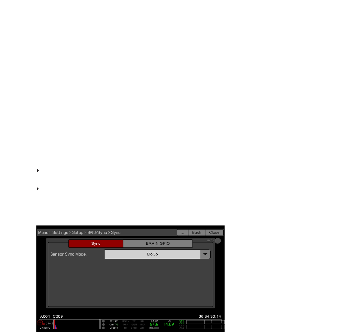
MOTION CONTROL (MOCO)
NOTE: When using MoCo, set the frame rate to be at least two times (2x) the fastest trigger rate used. When using
MoCo, REDCODE is calculated based on fps/2. Therefore, if you are in MoCo mode, and the frame rate is 100.83 fps,
the maximum REDCODE is calculated based on a frame rate of 50.415 fps.
NOTE: HDRX is not available when MoCo is enabled.
NOTE: Genlock and timecode can also be used with MoCo.
Motion Control (MoCo) is a form of sensor synchronization used to automate precision camera movements required
for special effects and difficult shots. Motion Control uses GPIO signals transmitted using the SYNC (GPI) and CTRL
(GPO) ports on the DSMC2 Base Expander.
For more information on GPIO connections, go to "Input/Output Connectors" on page219.
SET UP MOTION CONTROL
NOTE: Motion Control requires a DSMC2 Base Expander. For more information, go to "Input/Output Connectors" on
page219.
To set up Motion Control, follow the instructions below:
1. Connect the Motion Control device to the camera using a 3BNC-to-00 Sync Cable.
Sync In: Connect the white BNC connector to the Motion Control device and the 4-Pin 00B connector to the
SYNC port on the expander.
Sync Out: Connect the yellow BNC connector to the Motion Control device and the 4-Pin 00B connector to the
CTRL port on the expander.
2. Go to Menu > Settings > Setup > GPIO/Sync > Sync.
3. Select MoCo from the Sensor Sync Mode drop-down menu.
Figure: MoCo Sync Settings
4. Select the BRAIN GPIO tab.
5. Select Sync In from the GPI Function drop-down menu.
C OPYR I GHT © 2 01 9 R ED. C OM , LLC 955- 0159_V 7. 1, R EV -G | 186
EPIC-W GEMINI OPERATION GUIDE
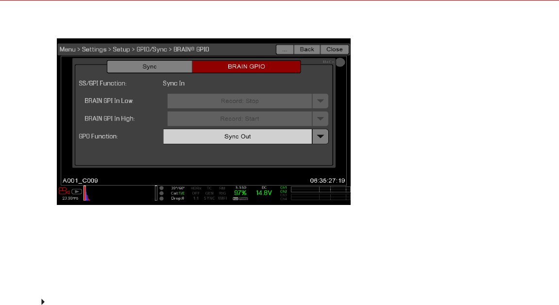
6. Select Sync Out from the GPO Function drop-down menu. (Optional)
Figure: MoCo BRAIN GPIO Settings
7. Supply a pulse from the Motion Control device to sync the shutter to the rising edge of the sync input.
NOTE: For more information, refer to the manufacturer’s instructions for the Motion Control device.
REQUIRED CABLE
790-0154, 790-0643: 3BNC-to-00 Sync Cable (required per SYNC and CTRL port used)
C OPYR I GHT © 2 01 9 R ED. C OM , LLC 955- 0159_V 7. 1, R EV -G | 187
EPIC-W GEMINI OPERATION GUIDE

COMPATIBLE TIMECODE DEVICES
The following timecode devices are compatible with the camera. Additional timecode devices may be compatible, but
have not yet been tested by RED.
Ambient ACL 202CT
Ambient LOCKIT ACL 203
Ambient ACL 204
Ambient ACC 501 Clockit Controller
Ambient ACD-301 Lockit Slate
Denecke SB-3 Syncbox Time-Code Generator
Sound Devices 788T
Sound Devices 744
Sound Devices PIX-240
Zaxcom Nomad 12
Zaxcom ZFR100
Zaxcom ZFR200
COMPATIBLE GENLOCK DEVICES
The following genlock devices are compatible with the camera. Additional genlock devices may be compatible, but
have not yet been tested by RED.
AJA® GEN10 HD/SD/AES Sync Generator with Universal Power Supply
Ambient ACL 202CT
Ambient ACL 203
Ambient ACL 204
Denecke SB-T
Evertz Master Clock 5600MSC
NOTE: Ensure that your genlock device provides a full-strength genlock signal to each camera. Splitting a genlock
signal weakens it, which may compromise the sync between cameras.
C OPYR I GHT © 2 01 9 R ED. C OM , LLC 955- 0159_V 7. 1, R EV -G | 188
EPIC-W GEMINI OPERATION GUIDE

C OPYR I GHT © 2 01 9 R ED. C OM , LLC 9 55 -0 15 9_V 7. 1, R EV- G|189
EPIC-W GEMINI OPERATION GUIDE
CHAPTER 9:
UPGRADE CAMERA FIRMWARE
Your camera functionality may be upgraded by installing the latest firmware. Make a habit of frequently visiting RED
Downloads at www.red.com/downloads to check for new versions of camera firmware, updated operation guides, and
post production software.
VERIFY CURRENT CAMERA FIRMWARE
To see the firmware version that is currently installed on your camera, go to Menu > Settings > Maintenance >
System Status > Camera Info. A higher number reflects a later release.
UPGRADE CAMERA FIRMWARE
Install the most recent firmware. Unless otherwise specified in the release notes, you do not need to upgrade to any
firmware in between your current version and the most recent version available online.
NOTE: You must calibrate the sensor after upgrading the camera. For more information, go to "Sensor Calibration" on
page159.
NOTE: Preset, Look, and Custom Overlay files are preserved across upgrades to v6.2.3 or later.
NOTE: On Mac® computers with REDCINE-X PRO® installed, RED Watchdog mounts the SSD as Read-Only by
default, which means that you are unable to write files (including firmware upgrade files) to the SSD. Change the
Mount preference to Read-Write before attempting to copy firmware to the SSD.
1. Connect an SSD (RED MINI-MAG®) to your computer.
2. Download the most recent firmware for your camera from RED Downloads at www.red.com/downloads.
3. Unzip the firmware zip file.
4. Copy the force_upgrade folder and its contents to the top level of the SSD directory.
5. Eject or unmount the SSD, and then remove the SSD.
6. Ensure that the camera is turned off.
7. Insert the SSD with the force_upgrade folder into your camera.
8. Turn on the camera.
The upgrade runs automatically.
During upgrade, the fans run at high speed and the PWR and REC LEDs flash green. After approximately 15
seconds, the LEDs stop flashing and the camera turns off. Nothing displays on the external monitors during the
upgrade.
9. After the camera turns off, remove the SSD and wait 10 seconds.
10. Turn on the camera.
The camera may take 30 seconds or longer to upgrade all of the attached RED devices. During this time the PWR
and REC LEDs flash green and nothing displays on the external monitors.
11. If this is your first time upgrading firmware, a pop-up menu opens with the Software License Agreement (SLA).
Select Agree. If you do not agree to the SLA, the camera cannot be used. The SLA continues to display until it is
accepted.

12. Verify that the firmware version listed matches the firmware version that you downloaded. For more information, go
to "Verify Current Camera Firmware" on the previous page.
13. Reformat the SSD before recording.
C OPYR I GHT © 2 01 9 R ED. C OM , LLC 955- 0159_V 7. 1, R EV -G | 190
EPIC-W GEMINI OPERATION GUIDE

C OPYR I GHT © 2 01 9 R ED. C OM , LLC 9 55 -0 15 9_V 7. 1, R EV- G|191
EPIC-W GEMINI OPERATION GUIDE
CHAPTER 10:
CAMERA SYSTEM MAINTENANCE
All RED® products are designed for rugged durability, but precision instruments demand proper care. Follow the
instructions in this chapter to clean, maintain, and store your devices.
WARNING: DO NOT rinse or immerse the camera or other accessories in water. Keep dry at all times.
WARNING: DO NOT use soaps, detergents, ammonia, acetone, alkaline cleaners, abrasive cleaning compounds, or
solvents. These substances may damage lens coatings and electronic circuitry.
WARNING: DO NOT use an excess of cleaning solution.
WARNING: DO NOT reuse swabs or wipes.
WARNING: DO NOT attempt to clean the sensor or optical cavity for any reason. If the sensor becomes dirty, submit
a Support ticket at https://support.red.com.
WARNING: DO NOT attempt to modify, dismantle, or open the camera, lens, or other accessory as doing so may
expose you to electric shock and serious injury. There are no user-serviceable parts inside. Alteration or repairs made
to the camera, lens, or other accessory, except by a RED®authorized service facility, voids all warranties.
WARNING: Use caution with compressed air and gas dusters, since the high pressure, oily residue, cold air,
particulates, and moisture may cause damage. You may use a filtered, non-residue gas duster to clean non-critical
areas, such as around the fans and other recesses on the exterior of the camera. Damage to the camera or other
components of the camera system caused by using compressed air or gas dusters is not covered under warranty.
WARNING: DO NOT use compressed air and gas dusters on the sensor or on any optics.
WARNING: DO NOT use compressed air and gas dusters on or around the integrated microphones on the front of the
BRAIN.
BRAIN AND ACCESSORY EXTERIOR SURFACES
Use a filtered, non-residue gas duster to clean non-critical areas, such as around the fans and other recesses on
the exterior of the camera.
Clean with a dry lint-free cloth. When cleaning your camera and accessories, remember that the devices are not
waterproof and moisture can damage electronic circuitry.
STORAGE
RED recommends that you store the camera and accessories in the water-resistant cases available in the RED Store at
www.red.com/store. These cases feature laser-cut foam to keep the camera and accessories secure.
WARNING: DO NOT store the camera or accessories in any place with extreme temperatures, direct sunlight, high
humidity, severe vibration, or strong magnetic fields.

CLEAN EVF SCREEN
NOTE: This section describes only how to clean the screen on the DSMC2® RED EVF, and not how to clean the entire
device.
This section explains how to clean the screen on the DSMC2 RED EVF. The screen is accessed by removing the
DSMC2 RED EVF Modular Optical Block.
Use an ionized rubber air bulb to clean the screen on the DSMC2 RED EVF. If there are still particles on the screen
after using an air bulb, gently wipe the screen with a rolled-up, particulate-free, non-abrasive optical-grade wipe.
NOTE: Cleaning the screen without first removing solid particles increases the risk of scratching the screen. As with
many screens, any type of physical contact with the screen may scratch the surface.
PROHIBITED EVF SCREEN CLEANERS
DO NOT use any of the items listed below to clean the screen on the DSMC2 RED EVF. These products have not
been tested on RED products and may cause damage or streaking.
Compressed air
Gas dusters
Solvents
Rubbing alcohol
Isopropyl alcohol
Windex®
Third-party cleaning kits
Pre-packaged lens cleaner containing any additives, such as detergent, anti-static compounds, or fragrance
RED Microfiber Bag
WARNING: Damage to any screens or other components of the camera system caused by using prohibited cleaners
is not covered under warranty.
CLEAN LCD SCREENS
NOTE: This section describes only how to clean the screen on each specified device, and not how to clean the entire
device.
This section explains how to clean the screens on the following devices:
RED PRO LCD
RED Touch LCD
RED PRO Touch LCD
DSMC2 SIDEKICK™
C OPYR I GHT © 2 01 9 R ED. C OM , LLC 955- 0159_V 7. 1, R EV -G | 192
EPIC-W GEMINI OPERATION GUIDE

APPROVED LCD SCREEN CLEANERS
Use only the following products to clean LCD screens:
Ionized rubber air bulb
Delkin Devices Sensor Solution®
Lens swabs
Dry optical wipes
RED Microfiber Bag
NOTE: Before cleaning the screen with swabs or wipes and a cleaning solution, ALWAYS use an ionized rubber air
bulb to remove any solid particles. Cleaning the screen without removing solid particles increases the risk of
scratching the screen.
PROHIBITED LCD SCREEN CLEANERS
DO NOT use any of the items listed below to clean LCD screens. These products have not been tested on RED
products and may cause damage or streaking.
Compressed air
Gas dusters
Solvents
Rubbing alcohol
Isopropyl alcohol
Windex
Pancro Professional Lens Cleaner (or equivalent)
Third-party cleaning kits
Pre-packaged lens cleaner containing any additives, such as detergent, anti-static compounds, or fragrance
WARNING: Damage to any screens or other components of the camera system caused by using prohibited cleaners
is not covered under warranty.
SCREEN STORAGE
Store any RED device with a screen in a RED Microfiber bag. Storing devices in a RED Microfiber bag preserves the
superior quality of the specialized AR and AS coatings on the LCDs.
Hand wash and air-dry the RED Microfiber bag regularly.
WATER DAMAGE
If your device has come in contact with water or you suspect water damage, submit a Support ticket at
https://support.red.com immediately.
WARNING: DO NOT attempt to power any device that may have water damage.
WARNING: DO NOT place the device in a container of rice, silica gel, or desiccant packets in an attempt to dry the
device.
C OPYR I GHT © 2 01 9 R ED. C OM , LLC 955- 0159_V 7. 1, R EV -G | 193
EPIC-W GEMINI OPERATION GUIDE

ADJUST BACK FOCUS
Adjust back focus by using the RED Focus or a focus chart. For more information about using the RED Focus, see the
RED Focus Operation Guide, available at www.red.com/downloads.
The camera also features a back focus adjustment screw. For more information, go to "BRAIN" on page13.
C OPYR I GHT © 2 01 9 R ED. C OM , LLC 955- 0159_V 7. 1, R EV -G | 194
EPIC-W GEMINI OPERATION GUIDE

C OPYR I GHT © 2 01 9 R ED. C OM , LLC 9 55 -0 15 9_V 7. 1, R EV- G|195
EPIC-W GEMINI OPERATION GUIDE
CHAPTER 11:
TROUBLESHOOT YOUR CAMERA
PERFORM A STRESS TEST
Perform a stress test before important projects to ensure the reliability and stability of your gear. A stress test subjects
your camera system and equipment to the increased stress of prolonged operation. If any components are developing
issues, this test will help identify those problems before you have an equipment failure during a major shoot.
1. Configure your camera.
2. Calibrate the sensor. For more information, go to "Sensor Calibration" on page159.
3. Enable the Sensor Test Pattern. For more information, go to "Enable/Disable Sensor Test Pattern" on page155.
4. Select the desired resolution.
5. Select the highest available frame rate.
6. Perform a secure format of the SSD.
7. Record a full SSD of footage.
8. Perform a secure format of the SSD.
9. Repeat Step 6 to Step 8 to test multiple SSDs.
10. If any errors occur, save a log file and submit a Support ticket at https://support.red.com.
NOTE: Problems or dropped frames found during the stress test display as “Errors” in the bottom of the user
interface.

GENERAL TROUBLESHOOTING
FIRMWARE DOES NOT UPGRADE
SYMPTOM
During an attempt to upgrade firmware, the PWR and REC LEDs flash red.
After an attempt to upgrade firmware, the firmware version does not change.
POTENTIAL RESOLUTIONS
After downloading the firmware upgrade file, ensure that you unzip the file before saving it to the SSD.
Ensure that the “force_upgrade” folder is saved to the top level of the SSD, and not to a subfolder.
GENERAL: MODULE, EXPANDER, OR LENS MOUNT NOT
FUNCTIONING
SYMPTOM
A module, expander, or lens mount is not functioning correctly, or is not communicating with the camera.
POTENTIAL RESOLUTIONS
Perform a Hardware Rediscover. For more information, go to "Rediscover (Hardware Rediscover)" on page156.
Upgrade your camera firmware. For more information, go to "Upgrade Camera Firmware" on page189.
Reset your camera’s default settings. For more information, go to "Reset Defaults" on page156.
CAMERA DOES NOT RECOGNIZE LENS
SYMPTOM
The camera does not recognize the attached lens.
POTENTIAL RESOLUTIONS
Ensure that the lens is compatible. For more information, go to "Lenses" on page252.
If using a PL lens, ensure that the camera is providing power to the lens: go to Menu > Settings > Setup > Lens
and select the Enable Power to Lens check box.
Detect the lens: go to Menu > Settings > Setup > Lens and select Detect Lens.
Perform a Hardware Rediscover. For more information, go to "Rediscover (Hardware Rediscover)" on page156.
C OPYR I GHT © 2 01 9 R ED. C OM , LLC 955- 0159_V 7. 1, R EV -G | 196
EPIC-W GEMINI OPERATION GUIDE

CAMERA DISPLAYS N/A FOR APERTURE
SYMPTOM
The camera displays N/A for aperture when a lens is attached.
POTENTIAL RESOLUTIONS
Ensure that your lens is completely locked in place.
Remove your lens mount. Check the connection points for damage or debris. Install your lens mount.
Perform a Hardware Rediscover. For more information, go to "Rediscover (Hardware Rediscover)" on page156.
Re-install your camera firmware.
If your camera is on beta firmware, downgrade to the release build.
If you are using a DSMC PL mount, go to Menu > Settings > Setup > Lens and ensure that power is enabled.
NOTE: Some lenses do not display the aperture information because they are incompatible. Some PL lenses do not
have i-technology data.
CANNOT SEE MENUS ON LCD TOUCHSCREEN
SYMPTOM
The LCD touchscreen does not display menus.
POTENTIAL RESOLUTION
Double-tap the LCD touchscreen to exit Clean mode.
SCREEN FREEZES OR DOES NOT DISPLAY
SYMPTOM
The screen freezes or does not display.
POTENTIAL RESOLUTION
Perform a Hard Restore. For more information, go to "Perform a Hard Restore" on page199.
INTERMITTENT MOTION JITTER
SYMPTOM
A slight, intermittent motion jitter displays on the monitor.
POTENTIAL RESOLUTIONS
If you calibrate the sensor using the Auto Calibration method, the calibration map updates in the background when
camera settings change. The update may cause slight, intermittent motion jitter to the image on the monitor. The jitter
characteristic only displays in live preview, and does not affect recorded footage. For more information on sensor
calibration, go to "Sensor Calibration" on page159.
C OPYR I GHT © 2 01 9 R ED. C OM , LLC 955- 0159_V 7. 1, R EV -G | 197
EPIC-W GEMINI OPERATION GUIDE

LCD FLICKER
SYMPTOM
The LCD or monitor is flickering.
POTENTIAL RESOLUTIONS
Set the LCD frequency to 60 Hz. For more information, go to "Frequency" on page91.
Use a different cable.
Ensure cables are properly attached.
LCD BLANK AT STARTUP
SYMPTOM
When you turn on the camera, the LCD does not show any image.
POTENTIAL RESOLUTIONS
Turn off the camera. Wait at least three (3) seconds, and then turn the camera back on.
CANNOT USE TOUCHSCREEN
SYMPTOM
Cannot control the camera via the touchscreen or the DSMC2® SIDEKICK™.
POTENTIAL RESOLUTIONS
Perform a Hard Restore. For more information, go to "Perform a Hard Restore" on the next page.
If you are using an external monitor, enable menus on the monitors and control the camera via the DSMC2
SIDEKICK:
Connect an SSD (RED MINI-MAG®) to your computer.
On the SSD, create a new folder, and name it force_preset.
Download the DSMC Toolkit from www.red.com/downloads.
Open the Preset_Files folder.
Open the folder that corresponds to the firmware version you are using.
Save the appropriate enable_menus file to the force_preset folder on your SSD.
Eject or unmount the SSD, and then remove the SSD.
Ensure that the camera is turned off.
Insert the SSD into your camera.
Turn on the camera. The camera automatically applies the preset.
NOTE: On Mac® computers with REDCINE-X PRO® installed, RED® Watchdog mounts the SSD as Read-Only by
default, which means that you are unable to write files (including firmware upgrade files) to the SSD. Change the
Mount preference to Read-Write before attempting to copy firmware to the SSD.
C OPYR I GHT © 2 01 9 R ED. C OM , LLC 955- 0159_V 7. 1, R EV -G | 198
EPIC-W GEMINI OPERATION GUIDE

TIGHTEN DC IN CONNECTOR
SYMPTOM
The DC IN connector nut is loose.
POTENTIAL RESOLUTIONS
Tighten the loose DC IN connector nut using a pair of heavy duty strong point tweezers.
WARNING: DO NOT OVERTIGHTEN.
Optional: Add a small amount of Loctite® 222 (low strength thread locker) to the threads of the DC IN connector
nut to prevent the connector from becoming loose again.
CAMERA DOES NOT TURN ON
SYMPTOM
The camera does not turn on (does not boot up), even when powered.
POTENTIAL RESOLUTIONS
Remove all accessories and power the camera using the power adaptor.
Perform a Hard Restore. For more information, go to "Perform a Hard Restore" below.
Remove all accessories and power the camera using the power adaptor.
If the camera does not turn on when a battery is attached, but does turn on when DC power is attached, toggle the
Auto Boot on Power switch to Off (identified by a black star).
PERFORM A HARD RESTORE
A common way to resolve camera firmware issues is to perform a Hard Restore. A Hard Restore functions like a
System Restore in that it changes all settings to the factory default values.
To perform a Hard Restore, follow the instructions below:
1. With the camera turned off, hold the PWR/REC key on the camera for 20 seconds or until the fans turn at a high
speed.
2. Release the PWR/REC key.
The screen displays correctly.
NOTE: User key settings reset as well as any other changes from the default settings.
C OPYR I GHT © 2 01 9 R ED. C OM , LLC 955- 0159_V 7. 1, R EV -G | 199
EPIC-W GEMINI OPERATION GUIDE

IMAGE APPEARS GRAINY
SYMPTOM
Image or footage appears grainy.
POTENTIAL RESOLUTIONS
Calibrate the sensor before recording additional clips. For more information, go to "Sensor Calibration" on
page159.
Check the histogram to ensure proper exposure. Noise occurs if an image is overexposed or underexposed.
Use the lowest REDCODE® compression possible for the settings you have selected.
Use a higher resolution.
Use Adaptive fan mode to regulate the camera temperature. Noise occurs when the temperature from the applied
calibration map is not in sync.
BLACK AND WHITE IMAGE
SYMPTOM
The display shows that an image is in black and white, and the menus are still in color.
POTENTIAL RESOLUTIONS
Check the Color Saturation setting. If the Saturation setting is set to a low value, change the Saturation to a higher
value.
Reset your camera’s default settings. For more information, go to "Reset Defaults" on page156.
INCORRECT COLOR TEMPERATURE
SYMPTOM
The camera color temperature is off and the image looks warmer or cooler than normal.
POTENTIAL RESOLUTIONS
Perform an auto white-balance. For more information, go to "White Balance" on page85.
Calibrate the sensor. For more information, go to "Sensor Calibration" on page159.
C OPYR I GHT © 2 01 9 R ED. C OM , LLC 955- 0159_V 7. 1, R EV -G | 200
EPIC-W GEMINI OPERATION GUIDE

TIMECODE OR GENLOCK DOES NOT FUNCTION
SYMPTOM
The SYNC, GEN, and/or TC light is red, yellow, or greyed out.
POTENTIAL RESOLUTIONS
Ensure that your timecode or genlock device is compatible. For more information, go to "Compatible Timecode
Devices" on page188 and "Compatible Genlock Devices" on page188.
Use a different cable.
Ensure that your timecode or genlock device settings match your project settings.
Ensure that your timecode or genlock device is set to the correct source. For more information, go to "Timecode"
on page174 and "Genlock" on page177.
Ensure that your Sensor Sync Mode is set to Genlock. For more information, go to "Sensor Sync" on page178.
Set the ACN (Ambient Clockit Network) to Off.
CAMERA DOES NOT RECOGNIZE OLPF
SYMPTOM
Your camera does not recognize the OLPF.
POTENTIAL RESOLUTIONS
Reinstall the OLPF. For more information, go to "Swap an Interchangeable OLPF" on page53.
Install a different OLPF.
If your camera still does not recognize the OLPF, submit a Technical Support request at https://support.red.com.
POSSIBLE HOT PIXEL
SYMPTOM
Your camera displays a possible hot pixel.
EXPLANATION
There may not be an issue with the pixel itself. The sensor can display a hot pixel when the sensor calibration is
outdated. Current camera settings and temperature can affect pixel calibration.
POTENTIAL RESOLUTIONS
Delete all user-generated calibration files and recalibrate the sensor. For more information, go to "Sensor
Calibration" on page159.
Upgrade your camera firmware. For more information, go to "Upgrade Camera Firmware" on page189.
Reset your camera’s default settings. For more information, go to "Reset Defaults" on page156.
Check your footage on a computer to confirm that the hot pixel is from the camera sensor, not your display
monitor.
If you determine that the camera sensor has a hot pixel, use the Pixel Masking tool in REDCINE-X PRO to remove
the hot pixel until the issue gets resolved. For more information, see the REDCINE-X PRO Operation Guide,
available at www.red.com/downloads.
C OPYR I GHT © 2 01 9 R ED. C OM , LLC 955- 0159_V 7. 1, R EV -G | 201
EPIC-W GEMINI OPERATION GUIDE

NO HDMI OR MON-1 SIGNAL
SYMPTOM
The HDMIor MON-1 port on the expander or module does not output a signal.
EXPLANATION
The secondary LCD/EVF port (on the side of the camera) and the HDMI/MON-1 port cannot be used at the same time.
For more information, go to "Monitor Preferences" on page90.
POTENTIAL RESOLUTIONS
If an LCD or EVF is connected to the secondary LCD/EVF port (on the side of the camera), remove the LCD or EVF.
Ensure that HDMI/HD-SDI monitoring/recording is set up correctly. For more information, go to "Record" on
page56.
C OPYR I GHT © 2 01 9 R ED. C OM , LLC 955- 0159_V 7. 1, R EV -G | 202
EPIC-W GEMINI OPERATION GUIDE

ERROR MESSAGES
“CRITICAL FAILURE” OR “SERIOUS ERROR” MESSAGES
SYMPTOM
When you upgrade or turn on the camera, the display shows a message with the phrase “Critical Failure” or “Serious
Error”.
POTENTIAL RESOLUTIONS
Update the camera firmware to the latest release build available for download at www.red.com/downloads.
Submit a Support ticket at https://support.red.com. Include the following with the request:
Log file. For more information, go to "Save a Log File" on page154.
List of devices, lens, and third-party accessories that were attached when the error occurred.
Method for powering the camera when the error occurred (include battery types, power devices, and power
cables).
"UPGRADE ATTACHED PERIPHERALS" MESSAGE
SYMPTOM
During an attempt to upgrade firmware, the display shows the message “Upgrade Attached Peripherals”. After turning
the camera off and then on, the same message displays, and then prompts you to turn off the camera.
POTENTIAL RESOLUTION
Ensure that you are upgrading your camera to the newest firmware version.
One (1) of your modules, expanders, or lens mounts (collectively known as “peripherals”) may be experiencing
issues. Remove all peripherals (except for media bay) and upgrade firmware. Then attach another peripheral, and
upgrade firmware again. Repeat this process, upgrading one (1) peripheral at a time. This will identify which
peripheral is experiencing issues. If there is a peripheral that will not upgrade, submit a Support ticket at
https://support.red.com.
PRESET COULD NOT BE APPLIED
SYMPTOM
The display shows the following message: “Preset Could Not Be Applied”.
POTENTIAL RESOLUTION
Turn off the camera, power it back up, and attempt to apply the preset that failed.
CANNOT CONTROL CAMERA EXTERNALLY
SYMPTOM
The camera displays the message “For reliable external control over Ethernet your camera’s hardware may need to be
upgraded. Please contact your Bomb Squad representative”.
POTENTIAL RESOLUTIONS
If you see this message, submit a Support ticket at https://support.red.com to have your hardware upgraded. You will
not be able to control the camera externally until the hardware is upgraded.
C OPYR I GHT © 2 01 9 R ED. C OM , LLC 955- 0159_V 7. 1, R EV -G | 203
EPIC-W GEMINI OPERATION GUIDE

ERROR 0X00000020 OR ERROR 0X20
SYMPTOM
The display shows one of the following messages:
Error 0x00000020. Please save log and send to RED Support.
ERROR 0x20. Media integrity error. Please secure format the SSD. If the issue persists, save log file and contact
RED Support with the log file, method of powering camera, and camera configuration.
POTENTIAL RESOLUTIONS
Perform a secure format of the SSD. For more information, see the DSMC Media Operation Guide, available at
www.red.com/downloads.
Update the camera firmware to the latest release build available for download at www.red.com/downloads.
Submit a Support ticket at https://support.red.com. Include the following with the request:
Log file. For more information, go to "Save a Log File" on page154.
List of devices, lens, and third-party accessories that were attached when the error occurred.
Method for powering the camera when the error occurred (include battery types, power devices, and power
cables).
ERROR 0X01D
SYMPTOM
The display shows the following message:"ERROR 0x01D. Possible hardware error. Please save log file and contact
RED Support with the log file and camera configuration."
POTENTIAL RESOLUTIONS
Submit a Support ticket at https://support.red.com. Include the following with the request:
Log file. For more information, go to "Save a Log File" on page154.
List of devices, lens, and third-party accessories that were attached when the error occurred.
Method for powering the camera when the error occurred (include battery types, power devices, and power cables).
C OPYR I GHT © 2 01 9 R ED. C OM , LLC 955- 0159_V 7. 1, R EV -G | 204
EPIC-W GEMINI OPERATION GUIDE

ERROR 0X11D
SYMPTOM
The display shows the following message:"Media integrity error. Please secure format the SSD. If the issue persists,
save log file and contact RED Support with the log file, method of powering camera, and camera configuration."
POTENTIAL RESOLUTIONS
Perform a secure format of the SSD. For more information, see the DSMC Media Operation Guide, available at
www.red.com/downloads.
Update the camera firmware to the latest release build available for download at www.red.com/downloads.
Submit a Support ticket at https://support.red.com. Include the following with the request:
Log file. For more information, go to "Save a Log File" on page154.
List of devices, lens, and third-party accessories that were attached when the error occurred.
Method for powering the camera when the error occurred (include battery types, power devices, and power
cables).
CAMERA KEEPS PROMPTING BLACK SHADE MESSAGE
SYMPTOM
Your camera keeps prompting you to black shade the camera.
POTENTIAL RESOLUTIONS
Ensure that you complete the sensor calibration process. For more information, go to "Sensor Calibration" on
page159.
Go to Menu > Settings > Maintenance > Calibrate and select user1 Calibration Map. Click Set.
Go to Menu > Settings > Maintenance > Calibrate and delete all user-created calibration maps. Then reset your
camera’s default settings. For more information, go to "Reset Defaults" on page156.
MOUNT TYPE: UNKNOWN
SYMPTOM
The error message “Mount type: Unknown” displays in Menu > Settings > Setup > Lens.
POTENTIAL RESOLUTIONS
Ensure that a lens mount is installed.
Ensure that a compatible lens mount is installed.
NOTE: Third-party lens mounts are not compatible with the camera.
C OPYR I GHT © 2 01 9 R ED. C OM , LLC 955- 0159_V 7. 1, R EV -G | 205
EPIC-W GEMINI OPERATION GUIDE

AUDIO BUFFER OVERFLOW WARNING
SYMPTOM
The error message "Audio Buffer Overflow" displays.
POTENTIAL RESOLUTIONS
Update the camera firmware to the latest release build available for download at www.red.com/downloads.
Perform a secure format of the SSD. For more information, see the DSMC Media Operation Guide, available at
www.red.com/downloads.
IMPORTANT: Ensure that data is backed up before formatting the media, since formatting erases all data on the
SSD.
Submit a Support ticket at https://support.red.com. Include the following with the request:
Log file. For more information, go to "Save a Log File" on page154.
List of devices, lens, and third-party accessories that were attached when the error occurred.
Method for powering the camera when the error occurred (include battery types, power devices, and power
cables).
List of file formats you were recording to before the error occurred (R3D, Apple ProRes, Avid DNxHD/HR).
PROXY BUFFER OVERFLOW WARNING
SYMPTOM
The error message "Proxy Buffer Overflow" displays.
POTENTIAL RESOLUTIONS
Update the camera firmware to the latest release build available for download at www.red.com/downloads.
Select a different recording file format and/or resolution from the Codec menu. For more information, go to "Select
Record File Format" on page133
Submit a Support ticket at https://support.red.com. Include the following with the request:
Log file. For more information, go to "Save a Log File" on page154.
List of devices, lens, and third-party accessories that were attached when the error occurred.
Method for powering the camera when the error occurred (include battery types, power devices, and power
cables).
List of file formats you were recording to before the error occurred (R3D, Apple ProRes, Avid DNxHD/HR).
C OPYR I GHT © 2 01 9 R ED. C OM , LLC 955- 0159_V 7. 1, R EV -G | 206
EPIC-W GEMINI OPERATION GUIDE

COOLING ADVISED MESSAGES
SYMPTOM
The display shows one of the following messages:
LCD is getting hot. Cooling advised.
LCD is hot. Cooling advised.
NOTE: The message identifies the affected LCD(s): LCD Top and/or LCD Left.
EXPLANATION
The LCD (screen) on the DSMC2 Touch 7.0" Ultra-Brite LCD may become hot to the touch in warm environments or
when exposed to direct sunlight.
If the camera detects that the LCD is getting hot, the display shows this message:
LCD is getting hot. Cooling advised.
Once the LCD becomes too hot, the display shows this message:
LCD is hot. Cooling advised.
If you do not want to see these messages, you can disable them. For more information, go to "Disable LCD
Temperature Warnings" on page94.
POTENTIAL RESOLUTIONS
Decrease the temperature of the screen.
Decrease the ambient temperature.
Shade the screen.
Angle the LCD so that the screen is not in direct sunlight.
Remove the LCD from direct sunlight.
C OPYR I GHT © 2 01 9 R ED. C OM , LLC 955- 0159_V 7. 1, R EV -G | 207
EPIC-W GEMINI OPERATION GUIDE

MEDIA BAY AND RED MINI-MAG ISSUES
SYMPTOMS
LEDs on media bay do not illuminate when expected.
RED MINI-MAG does not mount to camera.
POTENTIAL RESOLUTIONS
Ensure RED MINI-MAG is fully inserted in the media bay.
Perform a system restore.
Reformat the RED MINI-MAG on the computer. For more information, see the DSMC Media Operation Guide at
www.red.com/downloads.
Remove and reinstall the media bay. For more information, go to "Remove the Media Bay" below.
REMOVE THE MEDIA BAY
To troubleshoot issues with the media bay or SSD, you may need to remove and re-install the media bay. Unless you
are troubleshooting media-related issues, DO NOT remove the media bay.
WARNING: Before installing or removing the media bay, you MUST turn off the camera.
REQUIRED TOOL(S): T10 TORX driver
1. Turn off the camera.
2. Loosen the four (4) captive screws in a cross pattern (“X” pattern) using a T10 TORX driver.
3. Remove the media bay from the camera.
4. Inspect the connections and pins on the camera and ensure that they are clean and undamaged.
NOTE: DO NOT touch any part of the exposed boards or connectors.
5. Re-attach the media bay as soon as possible to prevent dust or debris from entering the camera. For more
information, go to "Install the Media Bay" below.
INSTALL THE MEDIA BAY
WARNING: Before installing or removing the media bay, you MUST turn off the camera.
REQUIRED TOOL(S): T10 TORX driver
1. Turn off the camera.
2. Place the media bay on the camera, so that the mounting holes of the media bay align with the screw holes of the
camera.
3. Use a T10 TORX driver to tighten the four (4) captive screws by about two (2) turns in a cross pattern (“X” pattern).
DO NOT FULLY TIGHTEN.
4. Tighten the four (4) captive screws evenly. DO NOT exceed 70 in-oz, or damage may occur.
WARNING: DO NOT OVERTIGHTEN.
C OPYR I GHT © 2 01 9 R ED. C OM , LLC 955- 0159_V 7. 1, R EV -G | 208
EPIC-W GEMINI OPERATION GUIDE
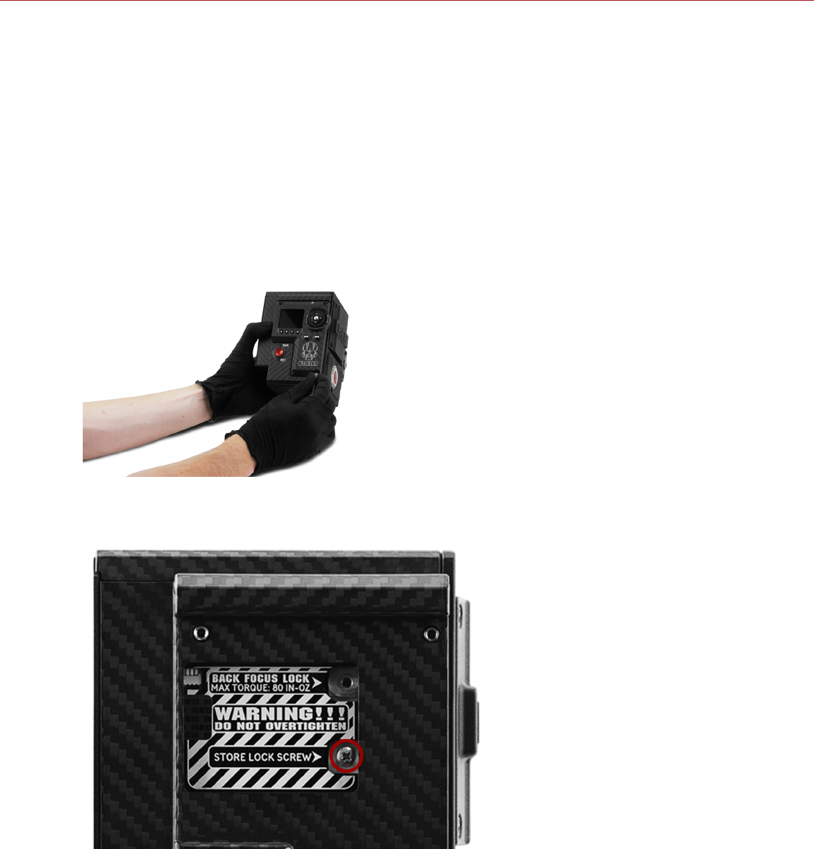
BACK FOCUS LOCK (LOCK SENSOR)
The camera has a Back Focus lock, which locks the sensor in place to prevent it from moving. Locking the sensor is
different from checking back focus.
To lock the sensor, follow the instructions below:
REQUIRED TOOL(S): T10 TORX driver, T8 TORX driver
WARNING: DO NOT adjust back focus when the sensor is locked in place by the Back Focus Lock, since that can
damage the Sensor Positioning System. Damage to the camera system caused by adjusting the back focus while the
sensor is locked is not covered under warranty.
1. Turn off the camera.
2. Use a T10 TORX driver to remove the side module (or side panel). For more information, go to "Configure Your
Camera" on page47.
Figure: Remove the Side Module/Panel
3. Use a T8 TORX driver to remove the screw from the Store Lock Screw position.
Figure: Remove Screw from Store Lock Screw Position
C OPYR I GHT © 2 01 9 R ED. C OM , LLC 955- 0159_V 7. 1, R EV -G | 209
EPIC-W GEMINI OPERATION GUIDE
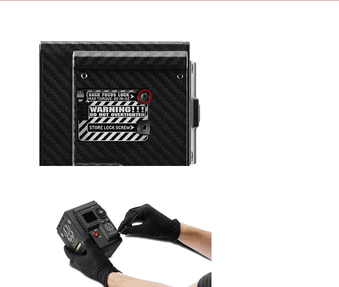
4. Use a T8 TORX driver to install the screw in the Back Focus Lock position. DO NOT exceed 80 in-oz, or damage
may occur.
WARNING: DO NOT OVERTIGHTEN.
Figure: Back Focus Successfully Locked
5. Reinstall the side module (or side panel). For more information, go to "Configure Your Camera" on page47.
Figure: Reinstall the Side Module/Panel
C OPYR I GHT © 2 01 9 R ED. C OM , LLC 955- 0159_V 7. 1, R EV -G | 210
EPIC-W GEMINI OPERATION GUIDE

C OPYR I GHT © 2 01 9 R ED. C OM , LLC 9 55 -0 15 9_V 7. 1, R EV- G|211
EPIC-W GEMINI OPERATION GUIDE
APPENDIX A:
TECHNICAL SPECIFICATIONS
EPIC-W 5K S35 TECHNICAL SPECIFICATIONS
EPIC-W 5K S35
SPECIFICATION DESCRIPTION
Sensor Type GEMINI® 15.4 Megapixel Dual Sensitivity CMOS
Effective Pixels 5120 x 3000
Sensor Size 30.72 mm x 18.00 mm (Diagonal: 35.61 mm)
Dynamic Range 16.5+ stops (Both Sensitivities)
Max Data Rates Up to 275 MB/s using RED MINI-MAG® (480GB, 512GB, 960GB & 1TB)
Up to 225 MB/s using RED MINI-MAG (120GB & 240GB)
REDCODE®
RAW Max Frame
Rates1
75 fps at 5K Full Height 1.7:1 (5120 x 3000)
96 fps at 5K Full Format (5120 x 2700), 120 fps at 5K 2.4:1 (5120 x 2160)
120 fps at 4K Full Format (4096 x 2160), 150 fps at 4K 2.4:1 (4096 x 1728)
150 fps at 3K Full Format (3072 x 1620), 200 fps at 3K 2.4:1 (3072 x 1296)
240 fps at 2K Full Format (2048 x 1080), 300 fps at 2K 2.4:1 (2048 x 864)
Playback Frame
Rates (Project
Time Base)
23.98, 24, 25, 29.97, 30, 47.95, 48, 50, 59.94, 60 fps, all resolutions
Best Available
REDCODE
Settings1
3:1 REDCODE at 5K Full Format (5120 x 2700) and 24 fps
9:1 REDCODE at 5K Full Format (5120 x 2700) and 96 fps
2:1 REDCODE at 4K Full Format (4096 x 2160) and 24 fps
7:1 REDCODE at 4K Full Format (4096 x 2160) and 120 fps
REDCODE RAW
Acquisition
Formats
5K Full Height 1.7:1 (5120 x 3000), 6:5 and Ana 2x, 1.3x
5K Full Format (5120 x 2700), 2:1, 2.4:1, 16:9, 4:1, 8:1, and Ana 2x, 1.3x
4K Full Format (4096 x 2160), 2:1, 2.4:1, 16:9, 3:2, 4:3, 6:5, 4:1, 8:1, and Ana 2x, 1.3x
3K Full Format (3072 x 1620), 2:1, 2.4:1, 16:9, 3:2, 4:3, 5:4, 6:5, 4:1, 8:1, and Ana 2x, 1.3x
2K Full Format (2048 x 1080), 2:1, 2.4:1, 16:9, 3:2, 4:3, 5:4, 6:5, 4:1, 8:1, and Ana 2x, 1.3x
Apple® ProRes ProRes 422 HQ, ProRes 422 and ProRes 422 LT at 4K (4096 × 2160) up to 30 fps
ProRes 4444 XQ and ProRes 4444 at 2K (2048 × 1080) up to 120 fps
ProRes 422 HQ, ProRes 422 and ProRes 422 LT at 2K (2048 × 1080) up to 120 fps

EPIC-W 5K S35
SPECIFICATION DESCRIPTION
Avid® Codecs DNxHR HQX at 4K (4096 × 2160) 12-bitup to 30 fps
DNxHR HQ and SQ at 4K (4096 × 2160) 8-bit up to 30 fps
DNxHR 444 at 2K (2048 × 1080) 12-bit up to 120 fps
DNxHR HQ and SQ (2048 × 1080) 8-bitup to 120 fps
DNxHD 444 and HQX (1920 × 1080) 10-bit up to 120 fps
DNxHD HQ and SQ (1920 × 1080) 8-bit up to 120 fps
Construction Magnesium and Aluminum Alloy
Weight 3.35 lbs (BRAIN® with Integrated Media Bay)
Operating
Temperature
0°C to 40°C (32°F to 104°F)
Storage
Temperature
–20°C to 50°C (–4°F to 122°F)
Relative Humidity 0% to 85% non-condensing
Color
Management
Improved in-camera color science
Supports 33×33×33, 32×32×32, 26×26×26, and 17×17×17 3D LUTs
Variable number of 3D LUT outputs with DSMC2® expander module
User programmable shaper 1D LUTs
Tetrahedral interpolation, 16-bit processing
Audio Integrated dual channel digital stereo microphones, uncompressed, 24-bit 48 kHz
Optional 2 additional channels with DSMC2 expander module, uncompressed, 24-bit 48 kHz
Remote Control Integrated R.C.P.™ WiFi antenna
Ethernet, RS232, and GPI Trigger with DSMC2 expander module
Monitor Outputs 3G-SDI (HD-SDI) and HDMI® with DSMC2 expander module
1080p RGB or 4:2:2, 720p RGB or 4:2:2
480p RGB or 4:2:2 (HDMI only)
SMPTE Timecode, HANC Metadata, 24-bit 48 kHz Audio
Monitor Options DSMC2 RED Touch 4.7" LCD, DSMC2 RED Touch 7.0" LCD and DSMC2 RED EVF (OLED) with
cable-free connection.
RED Touch 9.0" LCD, RED Touch 7.0" LCD, RED Touch 5.0" LCD, RED PRO 7" LCD, DSMC2
Touch 7.0" Ultra-Brite LCD, BOMB EVF (OLED) and BOMB EVF (LCOS) compatible with DSMC2
LCD/EVF Adaptor A or DSMC2 LCD/EVF Adaptor D, and LCD/EVF cable.
C OPYR I GHT © 2 01 9 R ED. C OM , LLC 955- 0159_V 7. 1, R EV -G | 212
EPIC-W GEMINI OPERATION GUIDE

EPIC-W 5K S35
SPECIFICATION DESCRIPTION
REDCINE-X
PRO® Delivery
Formats
4K: DPX, TIFF, OpenEXR (.RED via RRencode plugin)
2K: DPX, TIFF, OpenEXR (.RED via RRencode plugin)
1080p RGB 4:2:2, 720p 4:2:2 : QuickTime®, JPEG, Avid AAF, MXF
1080p 4:2:0, 720p 4:2:0 : H.264, .MP4
Video Editing
Software
Compatibility2
Adobe® Premiere® Pro, Avid Media Composer®, DaVinci Resolve®, Edius Pro®, Final Cut Pro®,
Vegas Pro®
1. REDCODE values and max frame rates may vary based on selected acquisition format, aspect ratio, project time base, Look Around setting,
and SSD. For more information, see the DSMC Media Operation Guide at www.red.com/downloads.
2. Third-party non-linear editing (NLE) applications may have limited compatibility with R3D files.
C OPYR I GHT © 2 01 9 R ED. C OM , LLC 955- 0159_V 7. 1, R EV -G | 213
EPIC-W GEMINI OPERATION GUIDE
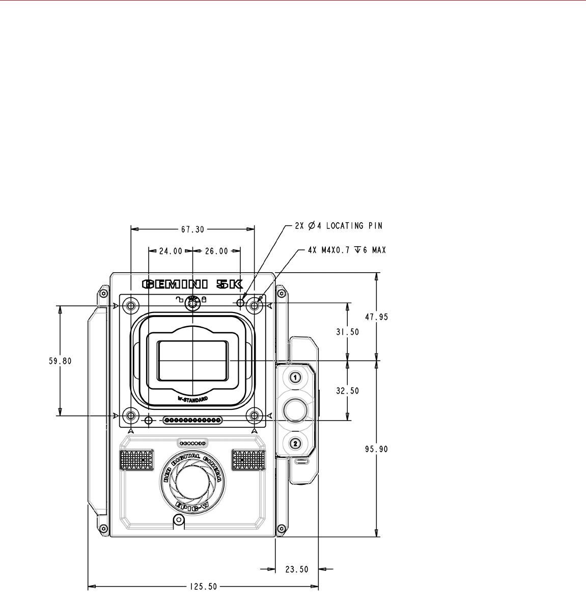
C OPYR I GHT © 2 01 9 R ED. C OM , LLC 9 55 -0 15 9_V 7. 1, R EV- G|214
EPIC-W GEMINI OPERATION GUIDE
APPENDIX B:
MECHANICAL DRAWINGS
EPIC-W 5K S35 BRAIN
NOTE: Dimensions are shown in mm.
The optical axis height of the camera is 95.90 mm.
FRONT VIEW
Figure: EPIC-W 5K S35 Front View
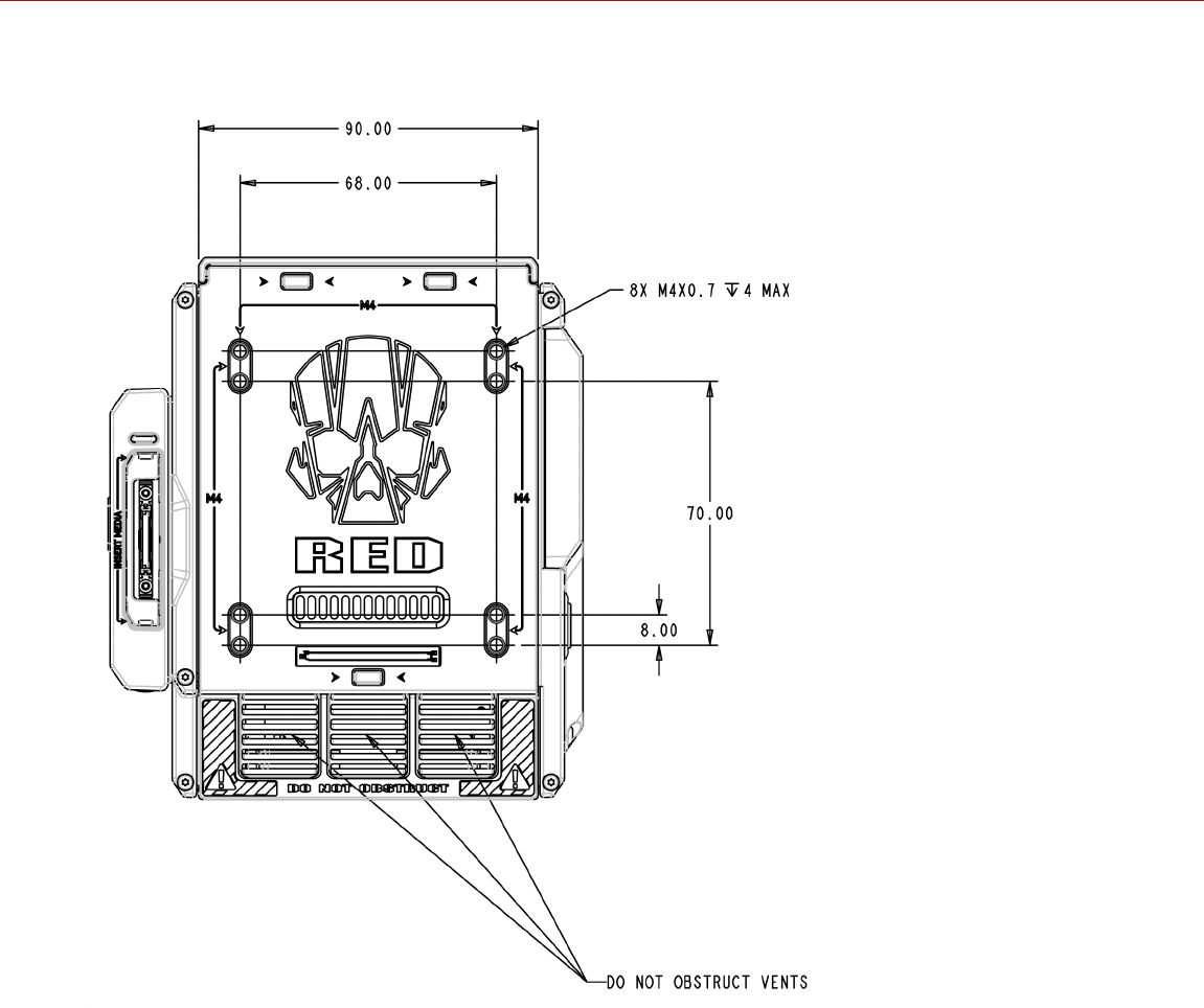
BACK VIEW
Figure: EPIC-W 5K S35 Back View
C OPYR I GHT © 2 01 9 R ED. C OM , LLC 955- 0159_V 7. 1, R EV -G | 215
EPIC-W GEMINI OPERATION GUIDE
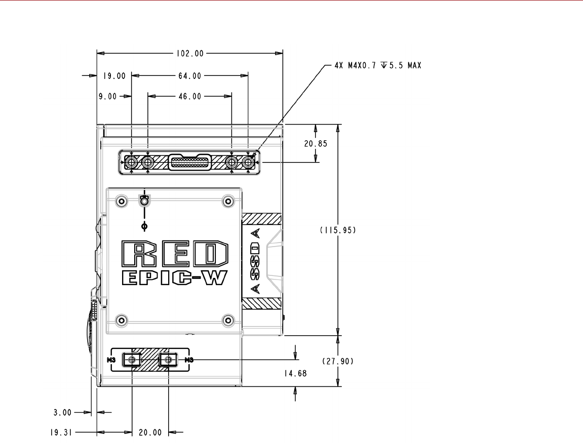
SIDE VIEW (RIGHT)
Figure: EPIC-W 5K S35 Side View (Right)
C OPYR I GHT © 2 01 9 R ED. C OM , LLC 955- 0159_V 7. 1, R EV -G | 216
EPIC-W GEMINI OPERATION GUIDE
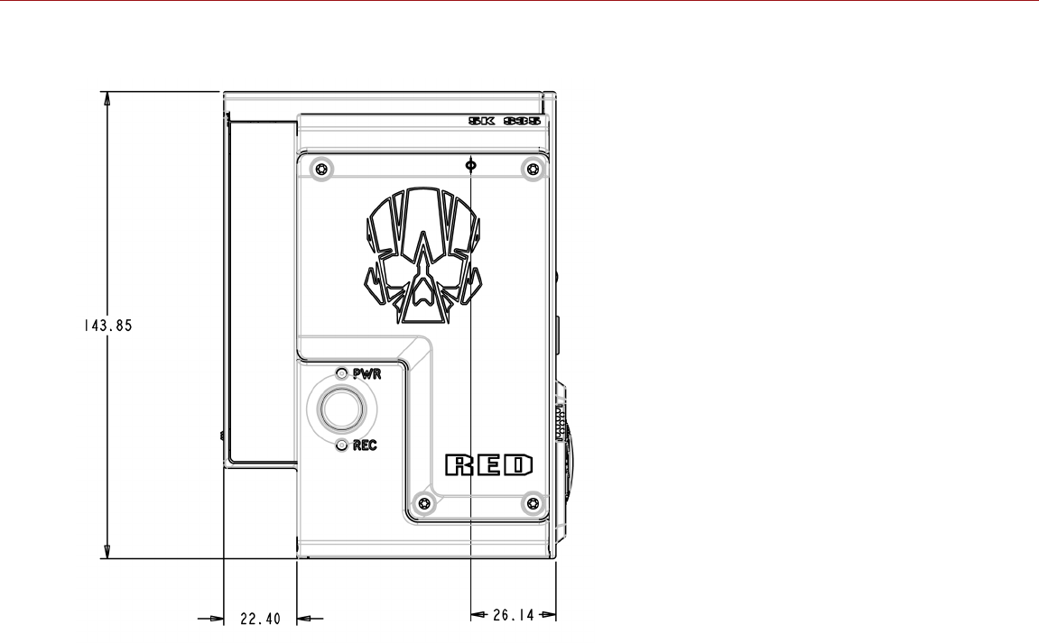
SIDE VIEW (LEFT)
Figure: EPIC-W 5K S35 Side View (Left)
C OPYR I GHT © 2 01 9 R ED. C OM , LLC 955- 0159_V 7. 1, R EV -G | 217
EPIC-W GEMINI OPERATION GUIDE
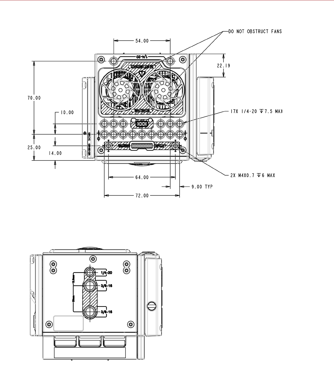
TOP VIEW
Figure: EPIC-W 5K S35 Top View
BOTTOM VIEW
Figure: EPIC-W 5K S35 Bottom View
C OPYR I GHT © 2 01 9 R ED. C OM , LLC 955- 0159_V 7. 1, R EV -G | 218
EPIC-W GEMINI OPERATION GUIDE

C OPYR I GHT © 2 01 9 R ED. C OM , LLC 9 55 -0 15 9_V 7. 1, R EV- G|219
EPIC-W GEMINI OPERATION GUIDE
APPENDIX C:
INPUT/OUTPUT CONNECTORS
This appendix provides pinout information for the input/output connectors on the following components:
DSMC2® Base Expander
DSMC2 V-Lock I/O Expander
DSMC2 REDVOLT Expander
DSMC2 Jetpack Expander
DSMC2 Jetpack-SDI Expander
DSMC2 Production Module
DSMC2 Tactical Top Plate
DSMC2 Production Top Plate
NOTE: When connecting a cable to a connector, align the key and red marker on the cable connector with the
corresponding key and marker on the device connection.
NOTE: Connector diagram images are for reference only. Diagrams are not to scale.
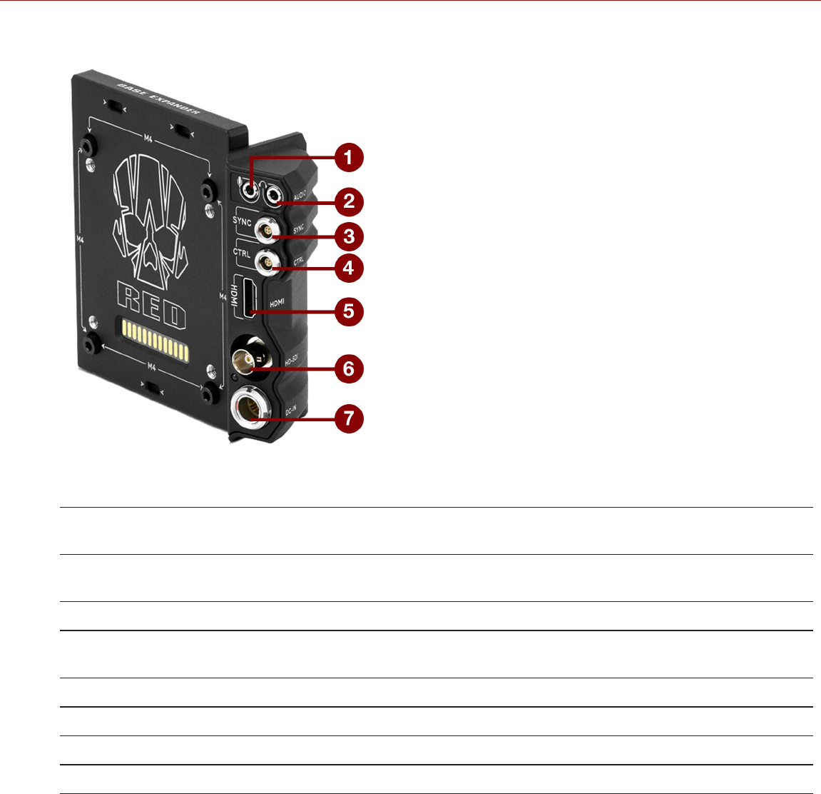
DSMC2 BASE EXPANDER
Figure: DSMC2 Base Expander
# CONNECTOR CONNECTOR
TYPE
DETAILS
1 Stereo
Microphone
3.5mm stereo "Stereo Microphone" on page241
2 Headphone Jack 3.5mm stereo "Headphone" on page242
3 SYNC 4-pin 00B "SYNC (Video Sync In) with SYNC Trigger Button Circuit" on
page230
4 CTRL 4-pin 00B "CTRL (RS232 Control)" on page234
5 HDMI®HDMI 1.2, Type A "HDMI Out" on page229
6 HD-SDI BNC "3G-SDI (HD-SDI) Out" on page227
7 DC IN 6-pin 1B DC-IN "DC IN (Power Input)" on page243
C OPYR I GHT © 2 01 9 R ED. C OM , LLC 955- 0159_V 7. 1, R EV -G | 220
EPIC-W GEMINI OPERATION GUIDE
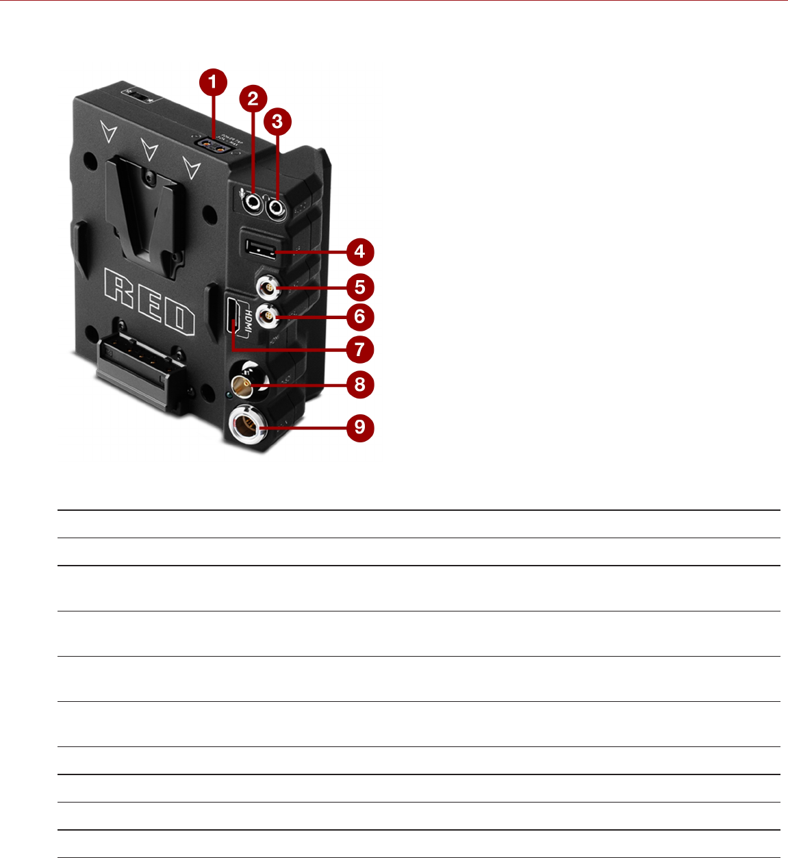
DSMC2 V-LOCK I/O EXPANDER
Figure: DSMC2 V-Lock I/O Expander
# CONNECTOR CONNECTOR TYPE DETAILS
1 AUX Power P-Tap 2-pin Female "AUX Power (P-Tap)" on page247
2 Stereo
Microphone
3.5mm stereo "Stereo Microphone" on page241
3 Headphone
Jack
3.5mm stereo "Headphone" on page242
4 USB Power USB 2.0, Type A (power
only)
"USB Power" on page246
5 SYNC 4-pin 00B "SYNC (Video Sync In) with Contact Closure Style Trigger Input" on
page232
6 CTRL 4-pin 00B "CTRL (RS232 Control)" on page234
7 HDMI®HDMI 1.2, Type A "HDMI Out" on page229
8 HD-SDI BNC "3G-SDI (HD-SDI) Out" on page227
9 DC IN 6-pin 1B DC-IN "DC IN (Power Input)" on page243
C OPYR I GHT © 2 01 9 R ED. C OM , LLC 955- 0159_V 7. 1, R EV -G | 221
EPIC-W GEMINI OPERATION GUIDE
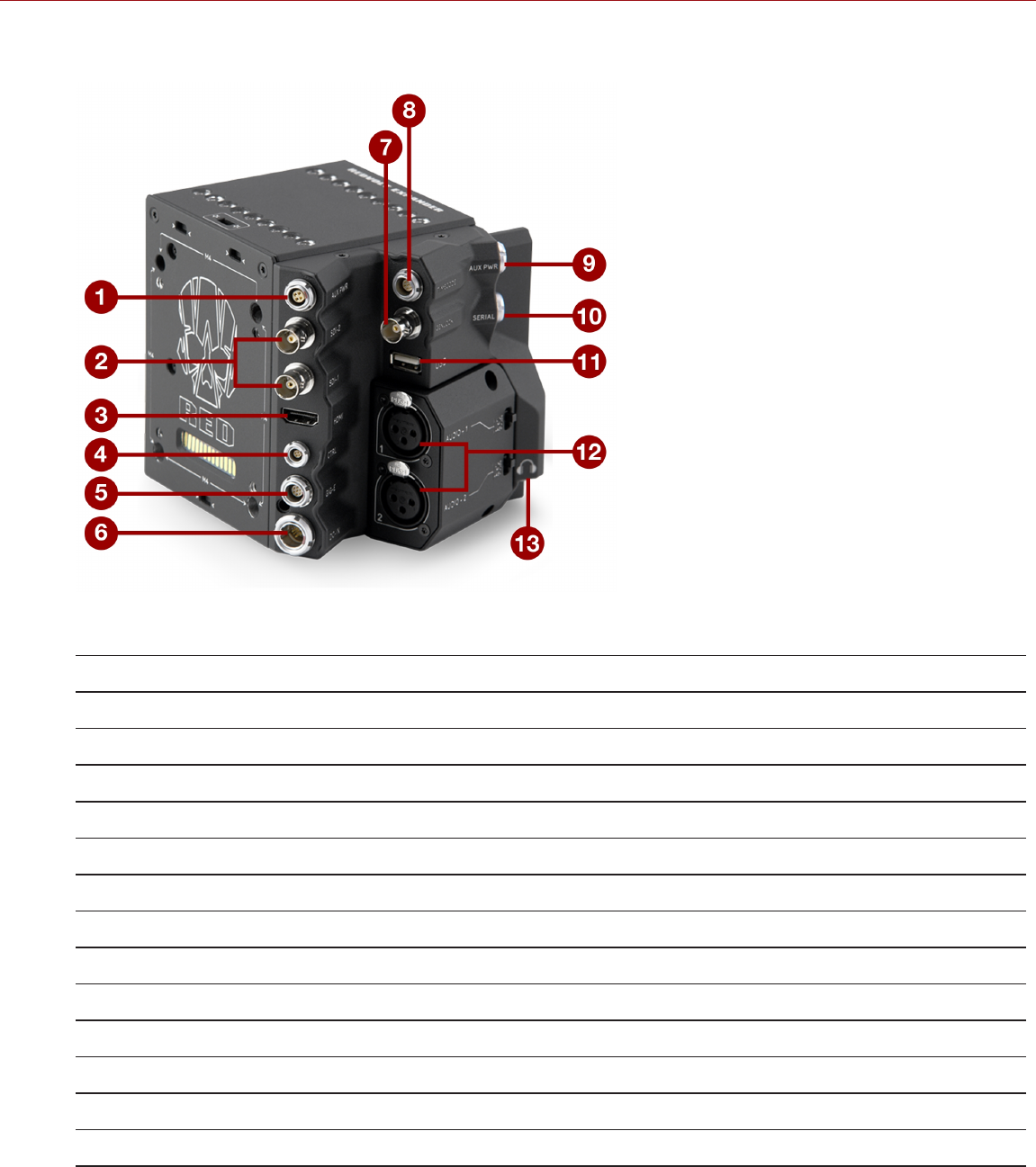
DSMC2 REDVOLT EXPANDER
Figure: DSMC2 REDVOLT Expander
# CONNECTOR CONNECTOR TYPE DETAILS
1 AUX PWR 4-Pin 0B "AUX Power (4-Pin 0B)" on page246
2 SDI 1 and 2 BNC "3G-SDI (HD-SDI) Out" on page227
3 HDMI HDMI 1.2, Type A "HDMI Out" on page229
4 CTRL 4-pin 00B "CTRL (RS232 Control)" on page234
5 GIG-E 9-pin 0B "GIG-E (Ethernet)" on page238
6 DC IN 6-pin 1B DC-IN "DC IN (Power Input)" on page243
7 GENLOCK BNC "Genlock" on page236
8 TIMECODE 5-Pin 0B "Timecode" on page237
9 AUX PWR 2-Pin 0B "AUX Power 2-Pin 0B, 3.0A" on page244
10 SERIAL 7-pin 0B "Serial (RS232 Control)" on page235
11 USB USB 2.0 Type A (power only) "USB Power" on page246
12 AUDIO 1 and 2 3-pin full-size XLR "Audio 1 and 2" on page241
13 Headphone Jack 3.5mm stereo "Headphone" on page242
C OPYR I GHT © 2 01 9 R ED. C OM , LLC 955- 0159_V 7. 1, R EV -G | 222
EPIC-W GEMINI OPERATION GUIDE
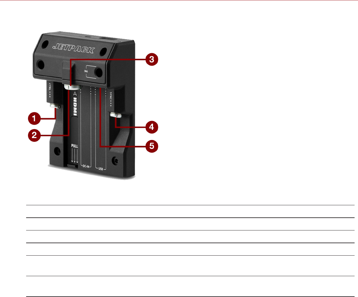
DSMC2 JETPACK EXPANDER
Figure: DSMC2 Jetpack Expander
# CONNECTOR CONNECTOR TYPE DETAILS
1 CTRL 4-pin 00B "CTRL (RS232 Control)" on page234
2 HDMI HDMI 1.2, Type A "HDMI Out" on page229
3 DC IN 6-pin 1B DC-IN "DC IN (Power Input)" on page243
4 SYNC 4-pin 00B "SYNC (Video Sync In) with Contact Closure Style Trigger Input" on
page232
5 USB USB 2.0, Type A (power
only)
"USB Power" on page246
C OPYR I GHT © 2 01 9 R ED. C OM , LLC 955- 0159_V 7. 1, R EV -G | 223
EPIC-W GEMINI OPERATION GUIDE
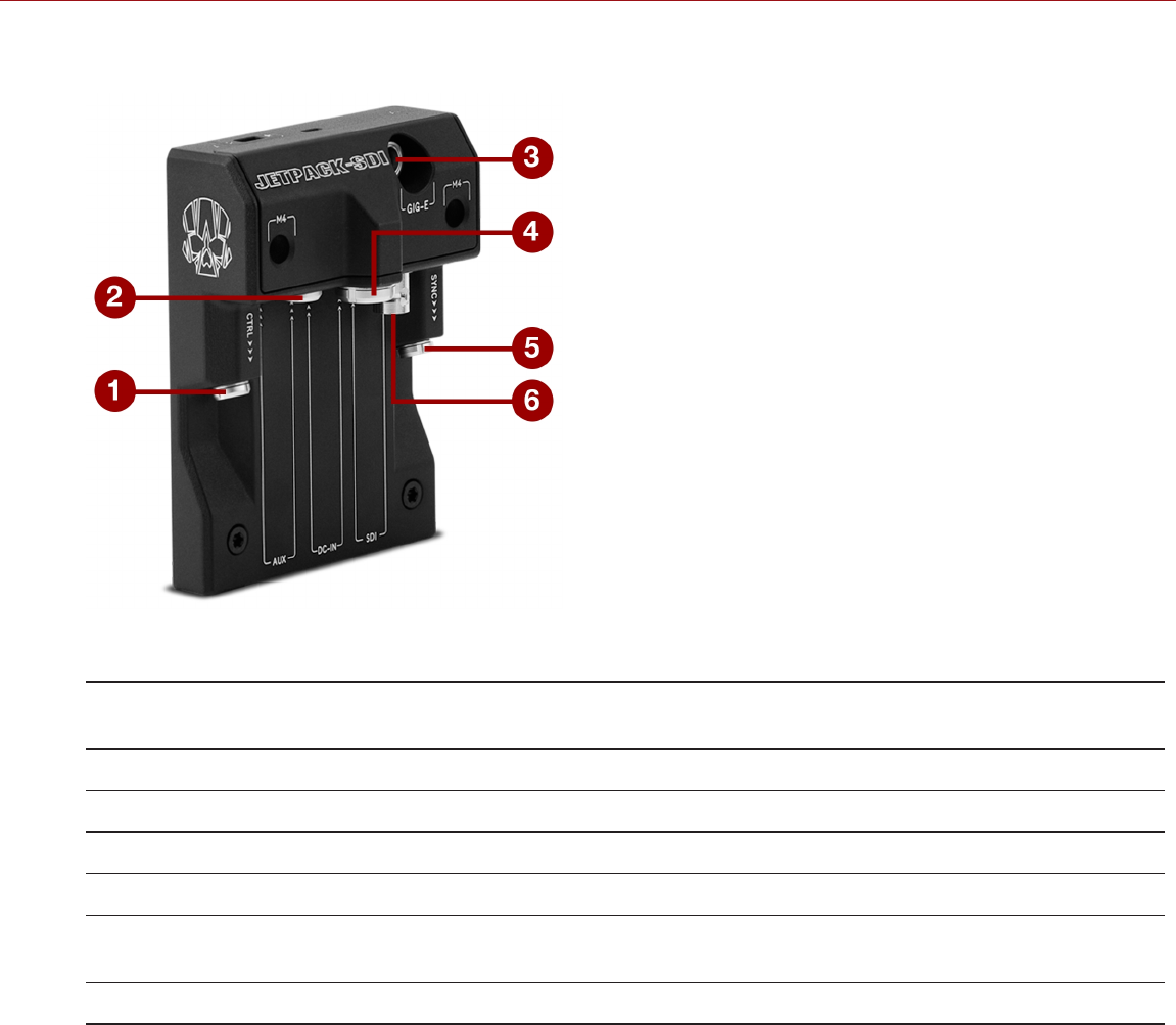
DSMC2 JETPACK-SDI EXPANDER
Figure: DSMC2 Jetpack-SDI Expander
# CONNECTOR CONNECTOR
TYPE
DETAILS
1 CTRL 4-pin 00B "CTRL (RS232 Control)" on page234
2 AUX 2-Pin 0B "AUX Power 2-Pin 0B, 1.5A" on page245
3 GIG-E 9-pin 0B "GIG-E (Ethernet)" on page238
4 DC IN 6-pin 1B DC-IN "DC IN (Power Input)" on page243
5 SYNC 4-pin 00B "SYNC (Video Sync In) with Contact Closure Style Trigger Input" on
page232
6 SDI BNC "3G-SDI (HD-SDI) Out" on page227
C OPYR I GHT © 2 01 9 R ED. C OM , LLC 955- 0159_V 7. 1, R EV -G | 224
EPIC-W GEMINI OPERATION GUIDE
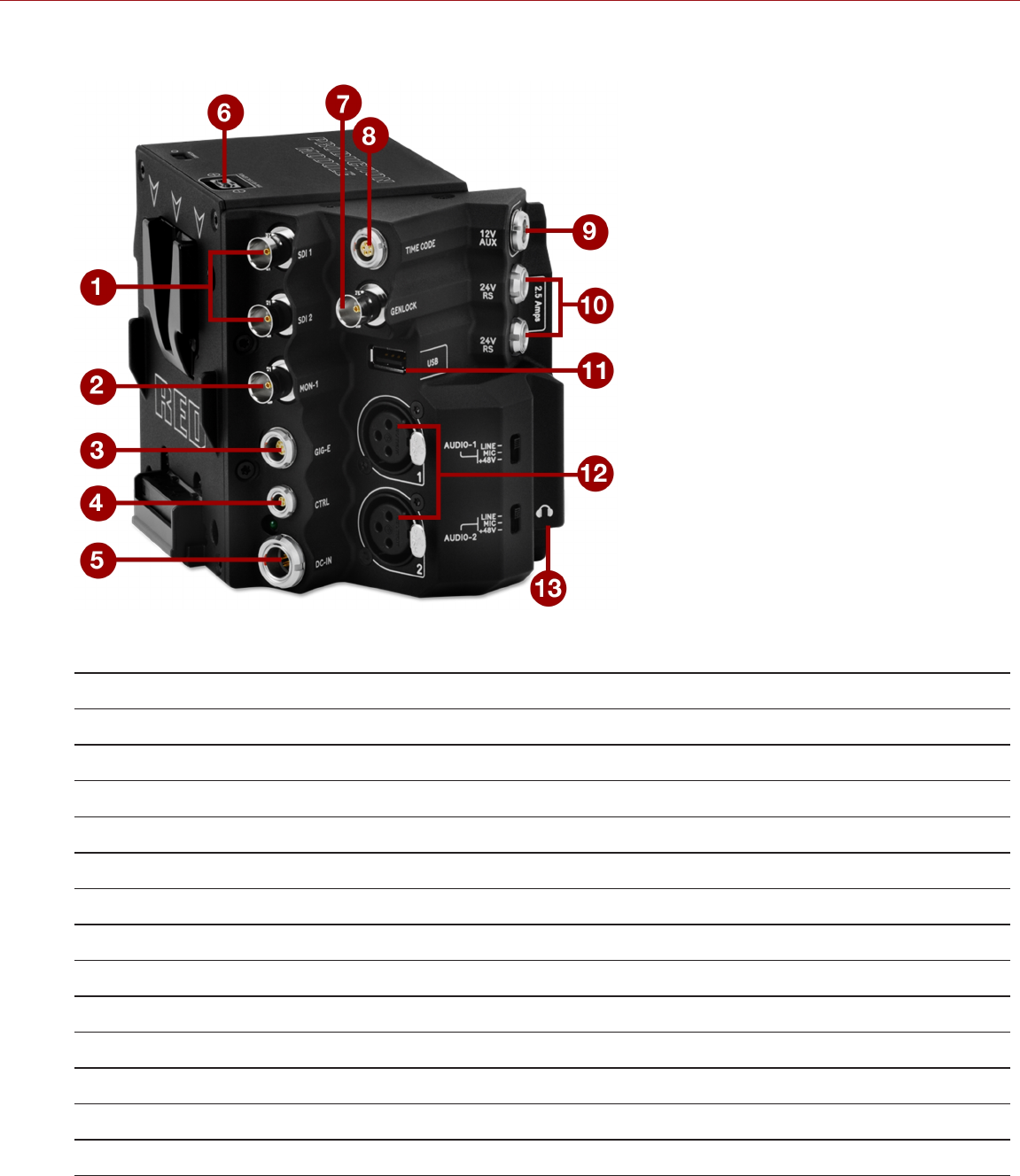
DSMC2 PRODUCTION MODULE (V-LOCK)
Figure: DSMC2 Production Module (V-Lock)
# CONNECTOR CONNECTOR TYPE DETAILS
1 SDI 1 and 2 BNC "3G-SDI (HD-SDI) Out" on page227
2 MON-1 BNC "MON-1" on page228
3 GIG-E 9-pin 0B "GIG-E (Ethernet)" on page238
4 CTRL 4-pin 00B "CTRL (RS232 Control)" on page234
5 DC IN 6-pin 1B DC-IN "DC IN (Power Input)" on page243
6 POWER TAP P-Tap 2-pin Female "AUX Power (P-Tap)" on page247
7 GENLOCK BNC "Genlock" on page236
8 TIMECODE 5-Pin 0B "Timecode" on page237
9 12V AUX 2-Pin 0B "AUX Power 2-Pin 0B, 3.0A" on page244
10 24V RS 1 and 2 3-pin Fischer "24V RS" on page240
11 USB USB 2.0 Type A (power only) "USB Power" on page246
12 AUDIO 1 and 2 3-pin full-size XLR "Audio 1 and 2" on page241
13 Headphone Jack 3.5mm stereo "Headphone" on page242
C OPYR I GHT © 2 01 9 R ED. C OM , LLC 955- 0159_V 7. 1, R EV -G | 225
EPIC-W GEMINI OPERATION GUIDE
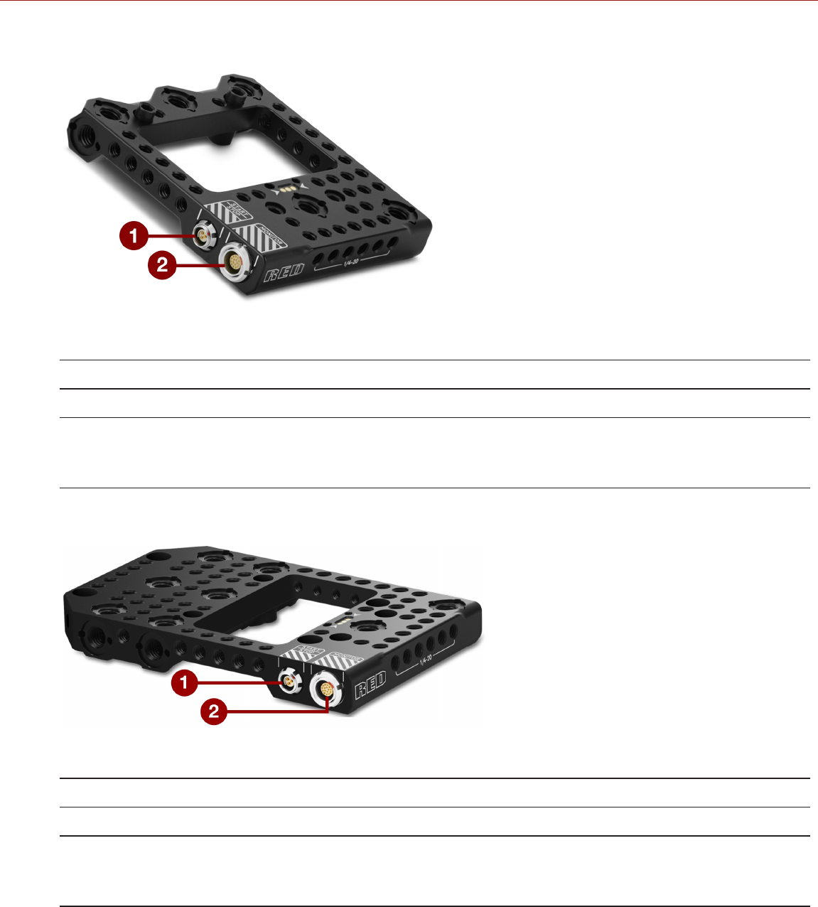
DSMC2 TACTICAL TOP PLATE
Figure: DSMC2 Tactical Top Plate
# CONNECTOR CONNECTOR TYPE DETAILS
1 START/STOP Fischer 3-pin 102 "START/STOP" on page239
2 MONITOR 16-Pin 1B LCD/EVF
connector
Custom digital video and power interconnection between the camera
and RED LCD/EVF;
Pinout not published
DSMC2 PRODUCTION TOP PLATE
Figure: DSMC2 Production Top Plate
# CONNECTOR CONNECTOR TYPE DETAILS
1 START/STOP Fischer 3-pin 102 "START/STOP" on page239
2 MONITOR 16-Pin 1B LCD/EVF
connector
Custom digital video and power interconnection between the camera
and RED LCD/EVF;
Pinout not published
C OPYR I GHT © 2 01 9 R ED. C OM , LLC 955- 0159_V 7. 1, R EV -G | 226
EPIC-W GEMINI OPERATION GUIDE

RECORD/MONITOR OUT PORTS
3G-SDI (HD-SDI) OUT
The following devices feature an HD-SDI connector:
DSMC2 Base Expander
DSMC2 V-Lock I/O Expander
DSMC2 REDVOLT Expander (labeled as “SDI-1” and “SDI-2”)
DSMC2 Jetpack-SDI Expander (labeled as “SDI”)
DSMC2 Production Module (labeled as “SDI-1” and “SDI-2”)
On the DSMC2 REDVOLT Expander and DSMC2 Production Module, SDI-1 and SDI-2 output a cloned 3G-SDI signal.
A standard 75 ohm BNC connector provides the following output:
Legal range of HD-SDI signals
Broadcast specification 3G-SDI (HD-SDI) video output (default mode is Clean)
Two (2) channels of embedded audio
Time of Day and Edge timecode
Record Tally flag
Clip name information (as SMPTE RP-188 VITC2 HANC metadata)
The 3G-SDI (HD-SDI) output provides the formats described in the table below:
3G-SDI (HD-SDI) OUTPUT FORMATS1
VIDEO FEED2FREQUENCY (HZ)3SMPTE STANDARD
720p 23.98, 24.00, 25.00, 29.97, 30.00, 50.00, 59.94 SMPTE ST 292-1 (1.485 Gbps)
1080p 10-bit 4:2:2 23.98, 24.00, 25.00, 29.97, 30.00 SMPTE ST 292 (1.485 Gbps)
1080p 10-bit 4:2:2 50.00, 59.94, 60.00 3G-SDI
SMPTE ST 424 (2.970 Gbps)
SMPTE ST 425 (2.970 Gbps)
1. Ensure that you select a frequency supported by your monitor.
2. The output is progressive scan (p); it does not support progressive segmented frame (PsF) or interlaced (i) scan formats.
3. The frequency options depend on project time base. If you have a non-drop frame project time base (such as 24.00), you can select only non-
drop frame frequencies. If you have a drop frame project time base (such as 23.98), you can select only drop frame frequencies.
75 OHM BNC CONNECTOR
PIN SIGNAL DESCRIPTION DIRECTION
Center 3G-SDI SMPTE ST 424 Out
Shield/Screen GROUND Camera ground N/A
COMPATIBLE CABLE
790-0341: RED® HD-SDI Cable (6')
C OPYR I GHT © 2 01 9 R ED. C OM , LLC 955- 0159_V 7. 1, R EV -G | 227
EPIC-W GEMINI OPERATION GUIDE

MON-1
The DSMC2 Production Module features a MON-1 out port. The DSMC2 Production Module converts an 8-bit RGB
HDMIsignal to a 10-bit 4:2:2 SDI feed, which is available via the MON-1 port. Due to this conversion, the color depth
of the signal is limited to 8-bit.
The MON-1 port provides an additional monitor feed that is separate from the SDI-1 and SDI-2 cloned feeds.
The MON-1 output provides the formats described in the table below:
MON-1 OUTPUT FORMATS1
VIDEO FEED2FREQUENCY (HZ)3
720p 50.00, 60.00
1080p 24.00, 25.00, 30.00, 50.00, 60.00
1. Ensure that you select a frequency supported by your monitor.
2. The output is progressive scan (p); it does not support progressive segmented frame (PsF) or interlaced (i) scan formats.
3. Supports only non-drop frame frequencies.
75 OHM BNC CONNECTOR
PIN SIGNAL DESCRIPTION DIRECTION
Center SDI SDI out Out
Shield/Screen GROUND Camera ground N/A
C OPYR I GHT © 2 01 9 R ED. C OM , LLC 955- 0159_V 7. 1, R EV -G | 228
EPIC-W GEMINI OPERATION GUIDE

HDMI OUT
The following expanders feature an HDMI 1.2 (Type A) connector:
DSMC2 Base Expander
DSMC2 V-Lock I/O Expander
DSMC2 Jetpack Expander
DSMC2 REDVOLT Expander
NOTE: For more information about HDMI wireless transmitter support, go to "HDMI Wireless Transmitters" below.
A standard HDMI connector provides the following output:
High-definition video output (default mode is Overlay)
Two (2) channels of embedded audio
The HDMI output provides the formats described in the table below:
HDMI OUTPUT FORMATS1
VIDEO FEED2FREQUENCY (HZ)
480p 50.00, 60.00
720p 24.00, 25.00, 30.00, 50.00, 60.00
1080p 24.00, 25.00, 30.00, 50.00, 60.00
1. Ensure that you select a frequency supported by your monitor.
2. The HDMI output is progressive scan (p); it does not support progressive segmented frame (PsF) or interlaced (i) scan formats.
COMPATIBLE CABLE
790-0331: RED HDMI Cable (5')
HDMI WIRELESS TRANSMITTERS
The HDMI connector supports HDMI wireless transmitters, so that you can transmit the HDMI signal to a remote HDMI
monitor. The HDMI connector supports industry-standard HDMI wireless transmitters.
NOTE: The DSMC2 Jetpack Expander features a spring- loaded retainer that keeps a mounted HDMI wireless
transmitter firmly in place. A wireless transmitter that is longer than 9.8 cm (including the HDMI connector) might not fit
in the retainer.
NOTE: The DSMC2 V-Lock I/O Expander, DSMC2 Jetpack Expander, and DSMC2 REDVOLT Expander have a USB
power out connector that provides 5 V at 1.5A, which powers most industry-standard HDMI wireless transmitters. For
more information, go to "USB Power" on page246.
C OPYR I GHT © 2 01 9 R ED. C OM , LLC 955- 0159_V 7. 1, R EV -G | 229
EPIC-W GEMINI OPERATION GUIDE

COMMUNICATION PORTS
SYNC (VIDEO SYNC IN) WITH SYNC TRIGGER BUTTON CIRCUIT
The DSMC2 Base Expander features a SYNC connector with a SYNC Trigger Button Circuit.
The 4-Pin 00B Sync Connector accepts timecode, genlock, and General Purpose Input (GPI) signals.
Figure: Front Face of the SYNC (Video Sync) Connector (Looking at the Camera)
4-PIN 00B SYNC CONNECTOR
PIN SIGNAL DESCRIPTION DIRECTION
1 GROUND Common ground N/A
2 SS/GPI Shutter sync/general purpose input trigger In
3 TIMECODE SMPTE unbalanced timecode input In
4 GENLOCK Tri-level sync input In
NOTE: Mating connector is FGG.00.304.CLAD.
C OPYR I GHT © 2 01 9 R ED. C OM , LLC 955- 0159_V 7. 1, R EV -G | 230
EPIC-W GEMINI OPERATION GUIDE
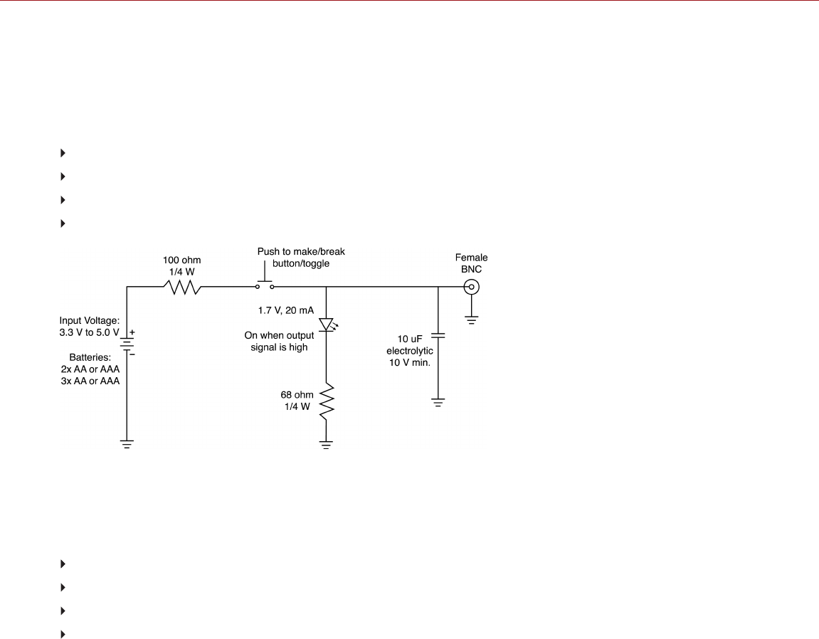
SYNC TRIGGER BUTTON CIRCUIT
The SYNC connector has a 3.3 V Schmitt trigger (5 V tolerant). The trigger is not a switch closure circuit, so it requires
that the trigger source supplies current. Both edges of the input signal may be used as a trigger.
NOTE: The SYNC trigger button circuit only applies to the DSMC2 Base Expander.
For example, this is the behavior of the circuit when the GPI trigger is used for record start/stop:
Start Record: On ground to 3.3 V transition
During Record: Hold at 3.3 V
Stop Record: On 3.3 V to ground transition
During Stop: Hold at ground
Figure: Trigger Button Circuit Diagram
NOTE: In the diagram above, values are approximate. Use standard values.
COMPATIBLE CABLES
790-0154, 790-0643: 3BNC-to-00 Sync Cable
790-0187, 790-0648: 4-Pin 00B-to-Flying Lead
790-0415: RED Start/Stop Cable (14-Pin 1B to SYNC, CTRL, BNC)
790-0428: RED Start/Stop Cable (14-Pin to 00B SYNC)
C OPYR I GHT © 2 01 9 R ED. C OM , LLC 955- 0159_V 7. 1, R EV -G | 231
EPIC-W GEMINI OPERATION GUIDE

SYNC (VIDEO SYNC IN) WITH CONTACT CLOSURE STYLE
TRIGGER INPUT
The following devices feature a SYNC connector with contact closure style trigger input:
DSMC2 Jetpack Expander
DSMC2 Jetpack-SDI Expander
DSMC2 V-Lock I/O Expander
The 4-Pin 00B Sync Connector accepts timecode, genlock, and General Purpose Input (GPI) signals. To operate the
GPI contact closure style trigger, short Pin 2 (GPI) to Pin 1 (ground).
WARNING: DO NOT apply voltage to Pin 2 (GPI).
Figure: Front Face of the SYNC (Video Sync) Connector (Looking at the Camera)
4-PIN 00B SYNC CONNECTOR
PIN SIGNAL DESCRIPTION DIRECTION
1 GROUND Common ground N/A
2 GPI General purpose input trigger; contact closure to Pin 1 In
3 TIMECODE SMPTE unbalanced timecode input In
4 GENLOCK Tri-level sync input In
NOTE: Mating connector is FGG.00.304.CLAD.
C OPYR I GHT © 2 01 9 R ED. C OM , LLC 955- 0159_V 7. 1, R EV -G | 232
EPIC-W GEMINI OPERATION GUIDE

CONTACT CLOSURE STYLE TRIGGER BUTTON CIRCUIT (SYNC)
The diagram below shows the contact closure style trigger button circuit on the SYNC connector.
Figure: Contact Closure Style Trigger Button Circuit Diagram (SYNC)
COMPATIBLE CABLES
790-0154, 790-0643: 3BNC-to-00 Sync Cable
790-0187, 790-0648: 4-Pin 00B-to-Flying Lead
790-0415: RED Start/Stop Cable (14-Pin 1B to SYNC, CTRL, BNC)
790-0428: RED Start/Stop Cable (14-Pin to 00B SYNC)
C OPYR I GHT © 2 01 9 R ED. C OM , LLC 955- 0159_V 7. 1, R EV -G | 233
EPIC-W GEMINI OPERATION GUIDE

CTRL (RS232 CONTROL)
The following devices feature a CTRL connector:
DSMC2 Base Expander
DSMC2 V-Lock I/O Expander
DSMC2 Jetpack Expander
DSMC2 Jetpack-SDI Expander
DSMC2 REDVOLT Expander
DSMC2 Production Module
The 4-Pin 00B CTRL Connector supports RS232 remote control for 3D camera communication and third-party
metadata ingest applications. For more information, go to "BRAIN GPIO" on page149.
The General Purpose Out (GPO) tally presents 3.3 V at a maximum of 0.04 A between pins 1 and 3. When used as a
record tally, the rising edge of the pulse indicates start of record, falling edge represents end of record.
For more information about controlling the camera via RS232, download the R.C.P.™ SDK , available at
www.red.com/developers.
Figure: Front Face of the CTRL (RS232) Connector (Looking at the Camera)
4-PIN 00B CTRL CONNECTOR
PIN SIGNAL DESCRIPTION DIRECTION
1 GROUND Common ground N/A
2 232 RX RS232 RX In
3 SS/GPO Shutter sync/general purpose output Out
4 232 TX RS232 TX Out
NOTE: Mating connector is FGG.00.304.CLAD.
COMPATIBLE CABLES
790-0154, 790-0643: 3BNC-to-00 Sync Cable
790-0187, 790-0648: 4-Pin 00B-to-Flying Lead
790-0415: RED Start/Stop Cable (14-Pin 1B to SYNC, CTRL, BNC)
C OPYR I GHT © 2 01 9 R ED. C OM , LLC 955- 0159_V 7. 1, R EV -G | 234
EPIC-W GEMINI OPERATION GUIDE

SERIAL (RS232 CONTROL)
The DSMC2 REDVOLT Expander features a SERIAL connector. The 7-Pin 0B SERIAL port connector supports RS232
RX, RS232 TX, and a General Purpose Input (GPI) trigger (active-low switch closure). The connector also offers
auxiliary power out, with a maximum sustained current draw of 1.5A.
To operate the GPI contact closure style trigger, short Pin 7 (GPI) to Pin 6 (ground).
The SERIAL connector was designed to support 6-pin 0B cables used with the RED Tactical Hand Controller (T.H.C.).
Although the connectors on those cables do not have pin 7 (GPI), the other 6 pins do match pins 1 to 6 on the SERIAL
connector.
Figure: Front Face of the SERIAL (RS232) Connector (Looking at the Camera)
SERIAL CONNECTOR
PIN SIGNAL DESCRIPTION DIRECTION
1 GND Camera ground N/A
2 RS232 RX RS232 RX In
3 RS232 TX RS232 TX Out
4 AUX OUT +11.5 to +17 VDC unregulated battery pass-through power Out
5 N/A No connection (NC) N/A
6 GND Camera ground N/A
7 GPI General Purpose In (GPI) trigger (active-low switch closure) In
NOTE: Mating connectors are FHG.0B.307.CLAD (right-angle) or FGG.0B.307.CLAD (straight).
C OPYR I GHT © 2 01 9 R ED. C OM , LLC 955- 0159_V 7. 1, R EV -G | 235
EPIC-W GEMINI OPERATION GUIDE
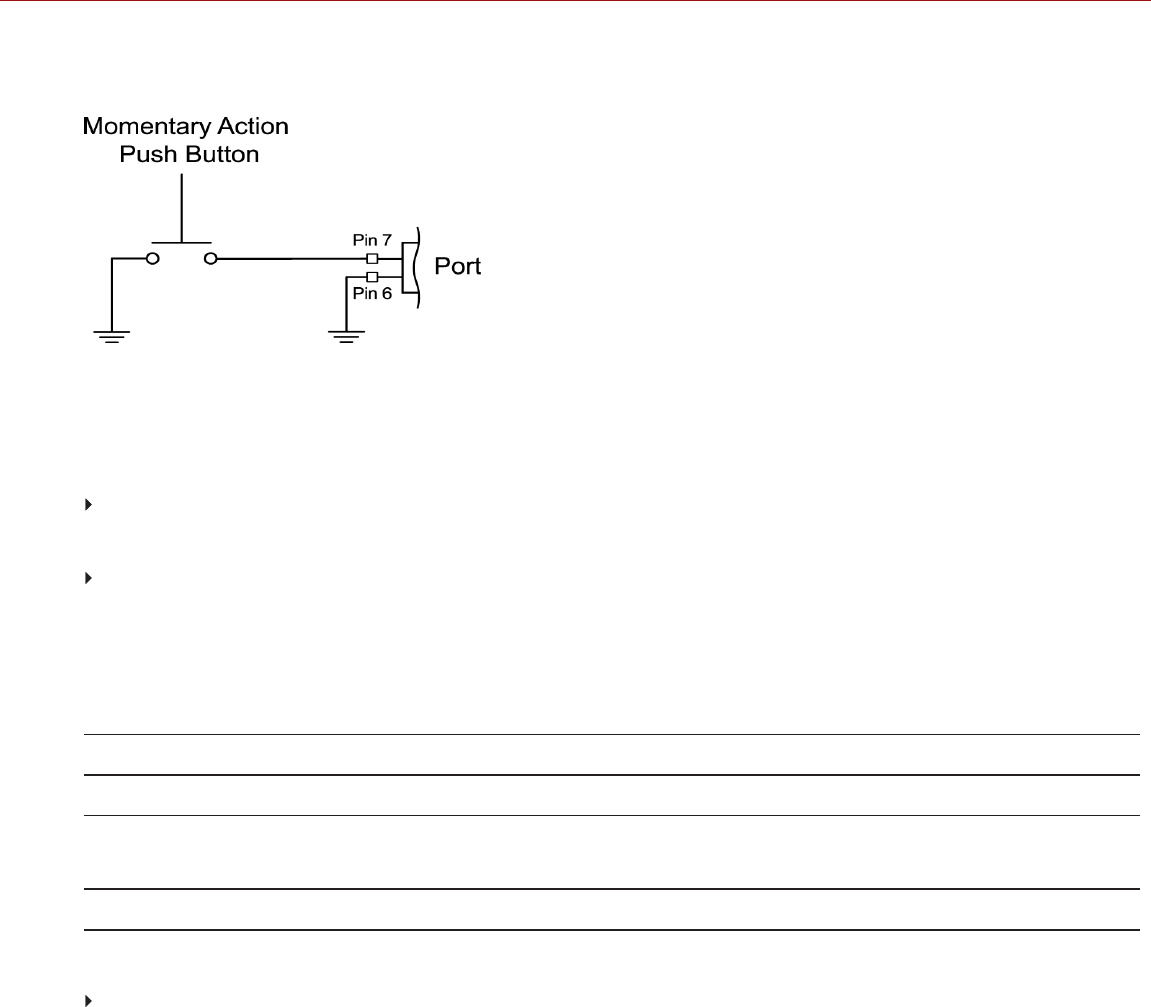
CONTACT CLOSURE STYLE TRIGGER BUTTON CIRCUIT
The diagram below shows the contact closure style trigger button circuit on the connector.
Figure: Contact Closure Style Trigger Button Circuit Diagram
COMPATIBLE CABLES
For GPI applications, you can use this cable:
790-0553, 790-0653: RED 7-Pin 0B-to-Flying Lead Serial Port Cable (6')
For non-GPI applications, you can use this 6-pin cable:
790-0444: R.C.P.®-to-T.H.C. Connector Cable 3'
GENLOCK
The DSMC2 REDVOLT Expander features a Genlock (GEN) connector.
The 75 ohm BNC connector accepts incoming sync and genlock signals.
75 OHM BNC CONNECTOR
PIN SIGNAL DESCRIPTION DIRECTION
Center SYNC SMPTE ST 274
RS 170A Tri-Level Sync
In
Shield/Screen GROUND Camera ground N/A
COMPATIBLE CABLE
790-0341: RED HD-SDI Cable (6’)
C OPYR I GHT © 2 01 9 R ED. C OM , LLC 955- 0159_V 7. 1, R EV -G | 236
EPIC-W GEMINI OPERATION GUIDE

TIMECODE
The following devices feature a TIMECODE connector:
DSMC2 REDVOLT Expander
DSMC2 Production Module
The LEMO EAG.0B.305.CLN connector supports SMPTE timecode input and output. Pins 2 and 3 can be used
together to receive a balance SMPTE 12M serial timecode input. Pin 2 can be used by itself (leave pin 3 open) to
receive a single-ended SMPTE 12M serial timecode input. Pin 5 is a timecode output.
Figure: Front Face of Timecode (LEMO EAG.0B.305.CLN) Connector (Looking at the Camera)
LEMO EAG.0B.305.CLN CONNECTOR
PIN SIGNAL DESCRIPTION DIRECTION
1 GROUND Camera Ground N/A
2 TIMECODE IN(S) Timecode input - SMPTE single ended In
3 N/A No connection (NC) N/A
4 +5 V OUT +5 V out, 200 mA max Out
5 TIMECODE OUT SMPTE 12 M Timecode output Out
NOTE: Mating connector is FHG.0B.305.CLAD.
COMPATIBLE CABLE
790-0212: Pro I/O Time Code Cable 3'
C OPYR I GHT © 2 01 9 R ED. C OM , LLC 955- 0159_V 7. 1, R EV -G | 237
EPIC-W GEMINI OPERATION GUIDE

GIG-E (ETHERNET)
The following devices feature a GIG-E connector.
DSMC2 Jetpack-SDI Expander
DSMC2 REDVOLT Expander
DSMC2 Production Module
The GIG-E 9-pin 0B connector provides a 1000BASE-T (IEEE 802.3ab) gigabit Ethernet connection for remote camera
setup, master/slave camera communication, and external metadata ingest. Since the GIG-E connector does not
support slower speeds (10BASE-T and 100BASE-T), ensure that any device you connect to supports 1000BASE-T.
Figure: Front Face of the GIG-E Connector (Looking at the Camera)
9-PIN 0B GIG-E CONNECTOR
PIN SIGNAL DESCRIPTION DIRECTION
1 BI_DC+ Data pair C+ N/A
2 BI_DC- Data pair C- N/A
3 BI_DD+ Data pair D+ N/A
4 BI_DD- Data pair D- N/A
5 BI_DA- Data pair A- N/A
6 BI_DA+ Data pair A+ N/A
7 BI_DB+ Data pair B+ N/A
8 BI_DB- Data pair B- N/A
9 N/A Do not connect N/A
NOTE: Mating connector is FGG.0B.309.CLAD.
COMPATIBLE CABLES
790-0159: RED GIG-E Straight-to-CAT5E Ethernet Cable (9')
790-0557, 790-0655: RED GIG-E Right-to-CAT5E Ethernet Cable (9')
790-0163: Master/Slave Gig-E Cable (4')
C OPYR I GHT © 2 01 9 R ED. C OM , LLC 955- 0159_V 7. 1, R EV -G | 238
EPIC-W GEMINI OPERATION GUIDE

START/STOP
The following devices feature a START/STOP connector:
DSMC2 Tactical Top Plate
DSMC2 Production Top Plate
The Fischer 3-pin 102 supports record start/stop via compatible third-party triggers.
Figure: START/STOP Connector (Looking at the Connector)
FISCHER 3-PIN CONNECTOR
PIN SIGNAL DESCRIPTION DIRECTION
1 GROUND Common ground N/A
2 N/A No connection (NC) N/A
3 R/S Active Low to start/stop record In
C OPYR I GHT © 2 01 9 R ED. C OM , LLC 955- 0159_V 7. 1, R EV -G | 239
EPIC-W GEMINI OPERATION GUIDE
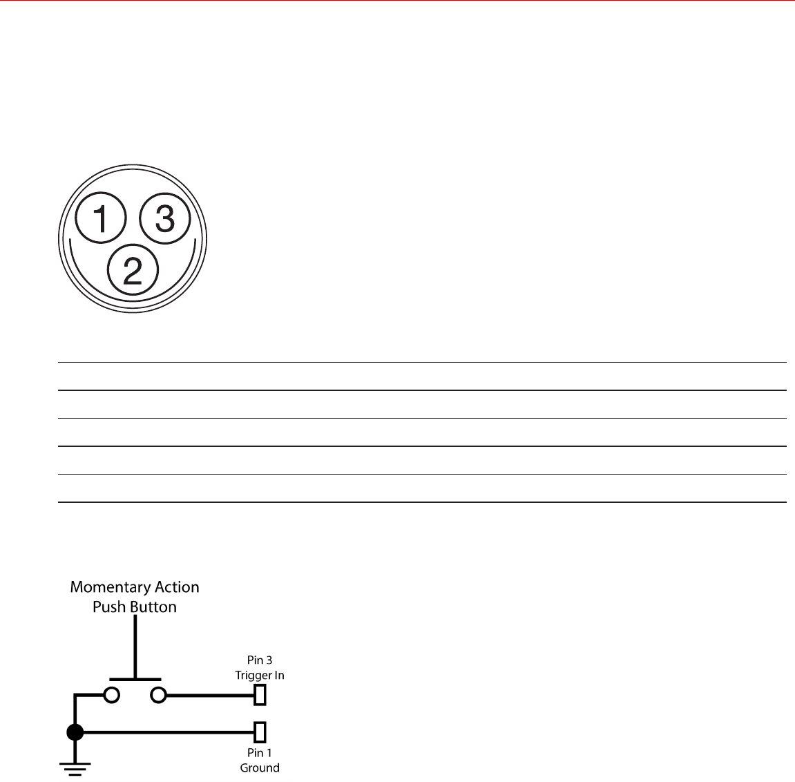
24V RS
The DSMC2 Production Module features two (2) 24V RS (run/stop) connectors.
The two (2) Fischer 3-pin 102 connectors supply a combined 24V power out at a maximum sustained current draw of
2.5A. Each connector also includes a run/stop (R/S) trigger input. To operate the contact closure style trigger, short
Pin 3 (R/S) to Pin 1 (ground).
WARNING: DO NOT apply voltage to Pin 3 (R/S).
Figure: 24V RS (Looking at the Connector)
FISCHER 3-PIN CONNECTOR
PIN SIGNAL DESCRIPTION DIRECTION
1 GROUND Common ground N/A
2 +24 V OUT +24 V out, 2.5A max (shared between the connectors) Out
3 R/S Active Low to start/stop record (3.3V pull up) In
CONTACT CLOSURE STYLE TRIGGER BUTTON CIRCUIT (24V RS)
The diagram below shows the contact closure style trigger button circuit on the 24V RS connector.
Figure: Contact Closure Style Trigger Button Circuit Diagram (24V RS)
C OPYR I GHT © 2 01 9 R ED. C OM , LLC 955- 0159_V 7. 1, R EV -G | 240
EPIC-W GEMINI OPERATION GUIDE

AUDIO PORTS
STEREO MICROPHONE
The following expanders feature a stereo microphone jack:
DSMC2 Base Expander
DSMC2 V-Lock I/O Expander
The 3.5mm stereo microphone provides two (2) channels of audio for recording.
HEADPHONE JACK
PIN SIGNAL DESCRIPTION DIRECTION
TIP LEFT Left channel audio In
RING RIGHT Right channel audio In
SLEEVE GND Camera ground N/A
AUDIO 1 AND 2
The following devices feature two (2) full-size XLR audio in connectors:
DSMC2 REDVOLT Expander
DSMC2 Production Module
The two (2) 3-pin XLR connectors provide input for two (2) audio channels. Each port supports 48 V 10mA phantom
power. Each input may be independently set to either line or microphone level. If a channel is set to microphone, you
can independently enable its 48 V phantom power output.
Figure: Front Face of Audio Input (3-PIN XLR) Connector (Looking at the Camera)
3-PIN XLR CONNECTOR
PIN SIGNAL DESCRIPTION DIRECTION
1 GROUND Camera ground N/A
2 MIC/LIN IN + Mic/Line input (+) 48 V phantom power In
3 MIC/LIN IN - Mic/Line input (-) 48 V phantom power In
C OPYR I GHT © 2 01 9 R ED. C OM , LLC 955- 0159_V 7. 1, R EV -G | 241
EPIC-W GEMINI OPERATION GUIDE

HEADPHONE
The following devices feature a headphone jack:
DSMC2 Base Expander
DSMC2 V-Lock I/O Expander
DSMC2 REDVOLT Expander
DSMC2 Production Module
The 3.5mm stereo jack provides two (2) channels of audio for monitoring. For maximum quality, use high impedance
headphones.
HEADPHONE JACK
PIN SIGNAL DESCRIPTION DIRECTION
TIP LEFT Left channel audio Out
RING RIGHT Right channel audio Out
SLEEVE GND Camera ground N/A
C OPYR I GHT © 2 01 9 R ED. C OM , LLC 955- 0159_V 7. 1, R EV -G | 242
EPIC-W GEMINI OPERATION GUIDE

POWER PORTS
DC IN (POWER INPUT)
The following devices feature a DC IN connector:
DSMC2 Base Expander
DSMC2 V-Lock I/O Expander
DSMC2 Jetpack Expander
DSMC2 Jetpack-SDI Expander
DSMC2 REDVOLT Expander
DSMC2 Production Module
The 6-Pin 1B DC-IN connector accepts DC input power from 11.5 V DC to 17 V DC. A built-in power conditioner
protects against reverse- polarity connections, electrostatic discharge (ESD), undervoltage, overvoltage, and
overcurrent.
WARNING: Both pairs of +VBATT and GROUND pins must be wired. Using a third-party power cable that wires only
one (1) pair of +VBATT and GROUND pins may damage the power supply or the camera. Damage to the power
supply or other components of the camera system caused by using an inappropriate power cable is not covered
under warranty.
Figure: Front Face of the DC In Power Input Connector (Looking at the Camera)
6-PIN 1B DC INPUT CONNECTOR
PIN SIGNAL DESCRIPTION
1 +VBATT Power input, +11.5 to +17 V DC
2 +VBATT Power input, +11.5 to +17 V DC
3 SCL-BATT Serial battery bus clock
4 GROUND Power return (camera ground)
5 GROUND Power return (camera ground)
6 SDA-BATT Serial battery bus data
NOTE: Mating connector is FGJ.1B.306.CWLD72Z.
C OPYR I GHT © 2 01 9 R ED. C OM , LLC 955- 0159_V 7. 1, R EV -G | 243
EPIC-W GEMINI OPERATION GUIDE

COMPATIBLE CABLES
790-0138: RED 2B-to-1B Power Adaptor Cable
790-0164, 790-0646: XLR Power Cable (10')
790-0165, 790-0647: XLR Power Cable (30")
AUX POWER 2-PIN 0B, 3.0A
The following devices feature an auxiliary power out connector (3.0A):
DSMC2 REDVOLT Expander
DSMC2 Production Module
The 2-Pin 0B connector (LEMO EEG.0B.302.CLL) supplies unregulated (+) 11.5 to 17 VDC battery pass-through power.
The maximum sustained current draw is 3.0A.
Figure: Front Face of Connector (Looking at the Camera)
LEMO EEG.0B.302.CLL CONNECTOR
PIN SIGNAL DESCRIPTION DIRECTION
1 GROUND Common ground N/A
2 +11.5 to +17 VDC +11.5 to 17 VDC unregulated battery pass-through power Out
NOTE: Mating connector is FGG.00.302.CLAD35Z.
COMPATIBLE CABLE
790-0410: RED W.M.D. Power Cable 2-Pin 1B to 2-Pin 0B (18")
C OPYR I GHT © 2 01 9 R ED. C OM , LLC 955- 0159_V 7. 1, R EV -G | 244
EPIC-W GEMINI OPERATION GUIDE

AUX POWER 2-PIN 0B, 1.5A
The DSMC2 Jetpack-SDI Expander features an auxiliary power out connector (1.5A):
The 2-Pin 0B connector (LEMO EEG.0B.302.CLL) supplies unregulated (+) 11.5 to 17 VDC battery pass-through power.
The maximum sustained current draw is 1.5A.
Figure: Front Face of AUX PWR Connector (Looking at the Camera)
LEMO EEG.0B.302.CLL CONNECTOR
PIN SIGNAL DESCRIPTION DIRECTION
1 GROUND Common ground N/A
2 +11.5 to +17 VDC +11.5 to 17 VDC unregulated battery pass-through power Out
NOTE: Mating connector is FGG.00.302.CLAD35Z.
COMPATIBLE CABLE
790-0410: RED W.M.D. Power Cable 2-Pin 1B to 2-Pin 0B (18")
C OPYR I GHT © 2 01 9 R ED. C OM , LLC 955- 0159_V 7. 1, R EV -G | 245
EPIC-W GEMINI OPERATION GUIDE

AUX POWER (4-PIN 0B)
The DSMC2 REDVOLT Expander features an auxiliary power out connector.
The LEMO EAG.0B.304.CLN connector supplies unregulated (+) 11.5 to 17 VDC battery pass-through power. The
maximum sustained current draw is 1.5A.
Figure: Front Face of AUX PWR Connector (Looking at the Camera)
LEMO EAG.0B.304.CLN CONNECTOR
PIN SIGNAL DESCRIPTION DIRECTION
1 GROUND Camera Ground N/A
2 GPI General purpose input trigger (GPI), use for trigger in In
3 GPO General purpose output trigger (GPO), use for tally out Out
4 +11.5 to +17 VDC +11.5 to 17 VDC unregulated battery pass-through power Out
NOTE: Mating connector is FGG.0B.304.CLAD.
COMPATIBLE CABLE
790-0552, 790-0652: RED 4-Pin 0B-to-Flying Lead AUX Power Cable (6')
USB POWER
The following devices feature a USB 2.0 (Type A) power out connector:
DSMC2 Jetpack Expander
DSMC2 V-Lock I/O Expander
DSMC2 REDVOLT Expander
DSMC2 Production Module
The USB power out connector supplies 5 V of power. The maximum sustained current draw is 1.5A.
You can use the USB power out connector to provide power to an attached HDMI wireless transmitter.
NOTE: The USB connector only offers power out, and does NOT support USB communication.
C OPYR I GHT © 2 01 9 R ED. C OM , LLC 955- 0159_V 7. 1, R EV -G | 246
EPIC-W GEMINI OPERATION GUIDE

AUX POWER (P-TAP)
The following devices feature an AUX power out connector:
DSMC2 V-Lock I/O Expander
DSMC2 Production Module
Figure: P-Tap Connector (Looking at Camera)
The AUX power out connector features an industry-standard P-Tap connector and supplies conditioned VBATT at a
maximum of 3.0A of power.
2-PIN P-TAP CONNECTOR
PIN SIGNAL DESCRIPTION DIRECTION
1 GROUND Common ground N/A
2 +11.5 to +17 VDC +11.5 to 17 VDC unregulated battery pass-through power Out
C OPYR I GHT © 2 01 9 R ED. C OM , LLC 955- 0159_V 7. 1, R EV -G | 247
EPIC-W GEMINI OPERATION GUIDE

C OPYR I GHT © 2 01 9 R ED. C OM , LLC 9 55 -0 15 9_V 7. 1, R EV- G|248
EPIC-W GEMINI OPERATION GUIDE
APPENDIX D:
LENS MOUNTS AND LENSES
LENS MOUNTS
This section describes camera lens mounts. Camera mounts may be configured with 19mm rods to accommodate
most cinematography lenses, matte boxes, and follow focus systems.
WARNING: All lenses are hot swappable. However, lens mounts are NOT HOT SWAPPABLE, meaning you cannot
remove or install lens mounts while the camera is turned on. Before installing or removing lens mounts, you MUST turn
off the camera. Failure to do so may result in damage to the lens mounts or camera that is not covered under
warranty.
DSMC RED MOTION MOUNT
The DSMC RED® MOTION MOUNT® S35 lens mount is a revolutionary and adjustable lens mount system for your
camera. By integrating a global shutter, temporal anti-aliasing soft shutter, and variable neutral density (ND) system
into a single lens mount, the DSMC RED MOTION MOUNT S35 lens mount delivers on-the-fly shutter adjustments to
reduce motion blur and temporal aliasing. The ND filter also includes a linear polarizer and IR filter for improved image
color and contrast.
For more information, see the MOTION MOUNT Operation Guide, available at www.red.com/downloads.
NOTE: HDRX is not availabe when the MOTION MOUNT Shutter Type is set to Soft or Square.
REMOVE A LENS MOUNT
NOTE: You can change lens mounts in the field. However, RED® recommends that you change lens mounts only in a
dust-free environment.
REQUIRED TOOL(S): T20 TORX® driver
1. Turn off the camera.
2. Attach the camera to a stable platform or position the camera on a clean and level work surface so that the lens
mount screws are accessible.
3. Remove the lens and any devices, cables, or other accessories that might interfere with removing the lens mount.
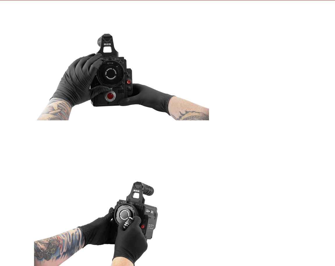
4. Depending on the lens mount, you may need to turn the locking ring slightly counter-clockwise so that you can
access the lens mount screws.
Figure: Turn Locking Ring Counter-Clockwise
5. Loosen and remove the four (4) M4x0.7 x 8 mm lens mount screws in a cross pattern (“X” pattern) using a T20
TORX driver.
NOTE: Some lens mounts have captive screws that are not removable.
NOTE: Screw removal may require a large handle T20 TORX driver and additional leverage.
Figure: Remove the Lens Mount Screws
C OPYR I GHT © 2 01 9 R ED. C OM , LLC 955- 0159_V 7. 1, R EV -G | 249
EPIC-W GEMINI OPERATION GUIDE

6. Remove the lens mount from the camera.
Figure: Remove the Lens Mount
C OPYR I GHT © 2 01 9 R ED. C OM , LLC 955- 0159_V 7. 1, R EV -G | 250
EPIC-W GEMINI OPERATION GUIDE
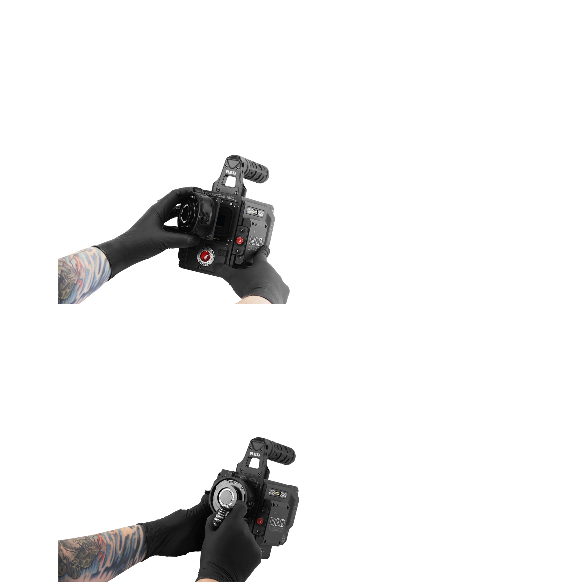
INSTALL A LENS MOUNT
NOTE: You can change lens mounts in the field. However, RED recommends that you change lens mounts only in a
dust-free environment.
REQUIRED TOOL(S): T20 TORX driver
1. Ensure that the camera is turned off and remove any accessories or cables that may interfere with installation.
2. Inspect the gold electrical contact pins on the front of the camera and the gold contact pads on the rear of the lens
mount to ensure that they are free of any contamination.
3. Align the lens mount on the front of the camera. The camera connection pins must align with the lens mount pins.
Figure: Align Lens Mount Pins
4. Depending on the lens, you may need to turn the locking ring slightly counter-clockwise so that you can access
the lens mount screws.
5. Replace and loosely tighten the four (4) M4x0.7 x 8 mm lens mount screws in a cross pattern (“X” pattern) using a
T20 TORX driver.
WARNING: DO NOT FULLY TIGHTEN.
NOTE: Some lens mounts have captive screws that are not removable.
Figure: Tighten Screws
C OPYR I GHT © 2 01 9 R ED. C OM , LLC 955- 0159_V 7. 1, R EV -G | 251
EPIC-W GEMINI OPERATION GUIDE

6. Tighten the four (4) lens mount screws evenly in a cross pattern (“X” pattern) using a T20 TORX driver. DO NOT
exceed 350 in-oz, or damage may occur.
WARNING: DO NOT OVERTIGHTEN.
7. After installation, a hardware rediscover or firmware upgrade may be required, particularly if you are installing a
MOTION MOUNT. To perform a hardware rediscover, go to Menu > Settings > Maintenance > Rediscover. A
system reboot is required after a hardware rediscover.
NOTE: If you need to replace any screws, submit a Support ticket at https://support.red.com.
LENSES
NOTE: Lenses are hot swappable.
LENS WEIGHT AND LENS SUPPORT
Use a lens support system when mounting heavy or long lenses to your camera.
When mounting a heavy or long lens, ensure that the full weight of the lens is never directly on the camera or lens
mount. Mount the lens to the support system first, and then carefully mount the lens to the camera.
WARNING: Failure to use lens supports appropriate for the lens and camera setup may lead to damage of the camera
and lens mount. Any damage caused by not using a lens support system is not covered under warranty.
POSITIVE LOCK (PL) LENSES
This section describes the appropriate method for attaching and detaching PL lenses. For more information, refer to
the original manufacturer’s instructions. This section also lists lenses supported by the camera PL mounts.
WARNING: ALWAYS protect your equipment, when it is not in use, by replacing lens caps and mount caps.
ATTACH PL LENSES
1. Rotate the locking ring counter-clockwise to release the camera mount cap.
2. Remove the rear lens cap and the camera mount cap.
3. Align the key and contact pads (if present) on the PL lens with the key and connector pins on the camera PL
mount.
4. Insert the lens into the camera PL mount.
5. Rotate the locking ring clockwise to secure the lens in place.
DETACH PL LENSES
1. Rotate the locking ring counter-clockwise to release the PL lens.
2. Remove the PL lens from the camera PL mount.
3. Replace the rear lens cap and camera mount cap when the lens is not in use.
CAMERA PL MOUNT SUPPORTED LENSES
The RED DSMC PL lens mounts and the DSMC RED MOTION MOUNT S35 Ti PL lens mount are compatible with
most standard PL mount cinema lenses and devices. For information about the compatibility of the DSMC RED
MOTION MOUNT S35 Ti PL lens mount, see the MOTION MOUNT Operation Guide at www.red.com/downloads.
WARNING: Using a non-standard PL mount lens or device with a camera PL mount may damage the camera and lens
mount. Any damage caused by not using a standard PL mount lens or device is not covered under warranty.
C OPYR I GHT © 2 01 9 R ED. C OM , LLC 955- 0159_V 7. 1, R EV -G | 252
EPIC-W GEMINI OPERATION GUIDE

FUJINON T2.9 CABRIO PREMIER PL LENSES
NOTE: The VTR switch on the lens is mapped to Record: Toggle by default. The VTR switch can be mapped to
another key.
NOTE: Fujinon lenses running older versions of lens firmware might not send correct data to the camera.
The following Fujinon® T2.9 Cabrio Premier PL lenses are compatible with all camera PL mounts, but must be
powered externally and configured a specific way:
Fujinon 14-35mm T2.9 Cabrio Premier PL
Fujinon 19-90mm T2.9 Cabrio Premier PL
To set up the Fujinon T2.9 Cabrio Premier PL lenses, follow the instructions below. Refer to the manufacturer’s
operation manual for detailed information about setting up and using the lens.
1. Attach the lens to the camera PL mount.
2. Ensure that the lens has lens firmware v6.4 or later (to check version in the camera, go to Menu > Settings >
Setup > Lens > Lens Info). Contact the manufacturer for lens firmware.
3. On the lens, set the Camera Communication switch to On.
4. On the lens, set the LDS, /i Select switch to Off.
5. Connect an external power source to the lens.
6. In the camera, to Menu > Settings > Setup > Lens.
7. Deselect the Enable Power to Lens check box.
NOTE: This option is only available when a camera PL mount is attached to the camera.
8. The lens should be successfully connected. However, if lens data does not display within 10 seconds, go to
Menu > Settings > Setup > Lens and select Detect Lens.
CANON PL MOUNT LENSES
The following Canon PL mount lenses are compatible with all camera PL mounts, but must be configured a specific
way:
Canon CN7x17 KAS S Cine-Servo 17-120mm T2.95
Canon CN20x50 IAS H Cine-Servo 50-1000mm
Requirements for using these Canon PL mount lenses:
The lens requires lens firmware v6.4 or later; contact the manufacturer for lens firmware.
In the camera, go to Menu > Settings > Setup > Lens, and select the Enable Power to Lens check box.
RED recommends using an external battery for the lens, since the lens mount provides a limited supply of power to
the lens.
C OPYR I GHT © 2 01 9 R ED. C OM , LLC 955- 0159_V 7. 1, R EV -G | 253
EPIC-W GEMINI OPERATION GUIDE

CANON EF LENSES
This section describes the appropriate method for attaching and detaching Canon® EF lenses. For more information,
refer to the original manufacturer’s instructions.
This section also lists lenses supported by the DSMC® Canon EF Mount.
WARNING: ALWAYS protect your equipment, when it is not in use, by replacing lens caps and mount caps.
ATTACH CANON EF LENSES
1. Rotate the secondary locking ring counter-clockwise to disengage.
2. Press the lens release button and rotate the lens cap counter-clockwise to remove the camera mount cap.
3. Remove the rear lens cap.
4. Align the red dot on the lens with the red dot on the DSMC Canon Mount and position the lens in the mount.
5. Turn the lens clockwise until it clicks into place.
6. Rotate the secondary locking ring clockwise to engage.
DETACH CANON EF LENSES
1. Rotate the secondary locking ring counter-clockwise to disengage.
2. Press and hold the lens release button. While holding the lens release button, turn the lens counterclockwise until it
stops and remove it from the camera mount.
3. Replace the rear lens cap and camera mount cap when the lens is not in use.
C OPYR I GHT © 2 01 9 R ED. C OM , LLC 955- 0159_V 7. 1, R EV -G | 254
EPIC-W GEMINI OPERATION GUIDE

DSMC CANON MOUNT SUPPORTED LENSES
The DSMC Canon Mount and DSMC RED MOTION MOUNT S35 Ti Canon (Captive) lens mount electronically support
the following lenses:
COMPATIBLE LENS TYPE FOCAL LENGTH
Canon CN-E Canon CN-E 18-80mm T4.4 COMPACT-SERVO1
Canon EF Canon EF 8-15mm f/4L Fisheye USM
Canon EF 11-24mm f/4L USM
Canon EF 14mm f/2.8L II USM
Canon EF 15mm f/2.8 Fisheye
Canon EF 15-85mm f/3.5 IS USM
Canon EF 16-35mm f/2.8L II
Canon EF 17-40mm f/4L
Canon EF 20mm f/2.8 USM
Canon EF 24mm f/1.4L II
Canon EF 24mm f/2.8
Canon EF 24mm f/2.8 IS USM
Canon EF 24-70mm f/2.8L
Canon EF 24-70mm f/2.8L II USM
Canon EF 24-70mm f/4L IS USM
Canon EF 24-105mm f/4L IS
Canon EF 28mm f/1.8 USM
Canon EF 28mm f/2.8
Canon EF 28mm f/2.8 IS USM
Canon EF 28-105mm f3.5 II USM
Canon EF 28-300mm f/3.5-5.6L IS
Canon EF 35mm f/1.4L
Canon EF 35mm f/2
Canon EF 35mm f/2 IS USM
Canon EF 40mm f/2.8 STM
Canon EF 50mm f/1.2L
Canon EF 50mm f/1.4 USM
Canon EF 50mm f/1.8 II
Canon EF 50mm f/1.8 STM
Canon EF 50mm f/2.5 Compact Macro
Canon EF 70-200mm f/2.8L IS
Canon EF 70-200mm f/2.8L IS with 1.4x Extender
Canon EF 70-200mm f/2.8L IS with 2x Extender
Canon EF 70-200mm f/2.8L IS II USM
C OPYR I GHT © 2 01 9 R ED. C OM , LLC 955- 0159_V 7. 1, R EV -G | 255
EPIC-W GEMINI OPERATION GUIDE

COMPATIBLE LENS TYPE FOCAL LENGTH
Canon EF Canon EF 70-200mm f/2.8 L IS II with 1.4x Extender
Canon EF 70-200mm f/2.8 L IS II with 2x Extender
Canon EF 70-200mm f/2.8L USM
Canon EF 70-200mm f/4L
Canon EF 70-200mm f/4L with 1.4x Extender
Canon EF 70-200mm f/4L with 2x Extender
Canon EF 70-300mm f/4.5-5.6 DO IS USM
Canon EF 70-300mm f/4-5.6L IS
Canon EF 70-300mm f/4-5.6L IS USM
Canon EF 85mm f/1.2L II
Canon EF 85mm f/1.8 USM
Canon EF 100mm f/2.0 USM
Canon EF 100mm f/2.8L Macro IS USM
Canon EF 100-400mm f/4.5-5.6L IS
Canon Zoom EF 100-400mm f/4.5L IS with 1.4x Extender
Canon Zoom EF 100-400mm f/4.5L IS with 2x Extender
Canon EF 100-400mm f/4.5-5.6L IS II USM
Canon EF 135mm f/2.0L
Canon EF 135mm f/2.0 L with 1.4x Extender
Canon EF 135mm f/2.0 L with 2.0x Extender
Canon EF 135mm f/2.8 Soft Focus
Canon EF 180mm f/3.5L Macro
Canon EF 180mm f/3.5L Macro with 1.4x Extender
Canon EF 180mm f/3.5L Macro with 2x Extender
Canon EF 200mm f/2.0L IS
Canon EF 200mm f/2.0L IS with 1.4x Exender
Canon EF 200mm f/2.0L IS with 2x Extender
Canon EF 200mm f/2.8L II
Canon EF 200mm f/2.8L II with 1.4x Extender
Canon EF 200mm f/2.8L II with 2x Extender
Canon EF 200-400mm f/4L IS USM
Canon EF 200-400mm f/4L IS USM 1.4x Extender
Canon EF 300mm f/2.8
Canon EF 300mm f/2.8L IS
Canon EF 300mm f/2.8L IS II USM
Canon EF 300mm f/2.8L IS with 1.4x Extender
Canon EF 300mm f/2.8L IS with 2x Extender
C OPYR I GHT © 2 01 9 R ED. C OM , LLC 955- 0159_V 7. 1, R EV -G | 256
EPIC-W GEMINI OPERATION GUIDE

COMPATIBLE LENS TYPE FOCAL LENGTH
Canon EF Canon EF 300mm f/2.8L IS II USM with 1.4x III Extender
Canon EF 300mm f/2.8L IS II USM with 2x III Extender
Canon EF 300mm f/4L IS
Canon EF 300mm f/4.0 L IS with 1.4x Extender
Canon EF 300mm f/4.0 L IS with 2.0x Extender
Canon EF 400mm f/2.8
Canon EF 400mm f/2.8 IS II USM
Canon EF 400mm f/2.8L IS
Canon EF 400mm f/2.8L IS with 1.4x Extender
Canon EF 400mm f/2.8L IS with 2x Extender
Canon EF 400mm f/4.0 DO IS
Canon EF 400mm f/4.0 DO IS with 1.4x Extender
Canon EF 400mm f/4.0 DO IS with 2x Extender
Canon EF 400mm f/5.6L
Canon EF 400mm f/5.6L with 1.4x Extender
Canon EF 400mm f/5.6L with 2x Extender
Canon EF 500mm f/4L IS
Canon EF 500mm f/4L IS USM
Canon EF 500mm f/4L IS II USM
Canon EF 500mm f/4L IS with 1.4x Extender
Canon EF 500mm f/4L IS with 2x Extender
Canon EF 500 f/4L IS II USM
Canon EF 600mm f/4L IS
Canon EF 600mm f/4L IS II USM
Canon EF 600mm f/4L IS with 1.4x Extender
Canon EF 600mm f/4L IS with 2x Extender
Canon EF 800mm f/5.6L IS
Canon EF 800mm f/5.6L IS with 1.4x Extender
Canon EF 800mm f/5.6L IS with 2x Extender
C OPYR I GHT © 2 01 9 R ED. C OM , LLC 955- 0159_V 7. 1, R EV -G | 257
EPIC-W GEMINI OPERATION GUIDE

COMPATIBLE LENS TYPE FOCAL LENGTH
Canon EF-S Canon EF-S 10-18mm f/4.5-5.6 IS STM2
Canon EF-S 10-22mm f/3.5-4.5 USM2
Canon EF-S 15-85mm f/3.5-5.6 IS USM
Canon EF-S 17-55mm f/2.8 IS USM
Canon EF-S 18-55mm f/3.5-5.6 IS2
Canon EF-S 18-55mm f/3.5-5.6 IS II
Canon EF-S 18-135mm f/3.5-5.6 IS STM2
Canon EF-S 18-200mm f/3.5-5.6 IS
Canon EF-S 24mm f/2.8 STM
Canon EF-S 60mm f/2.8 Macro USM
Sigma Sigma 10-20mm f/3.5 EX DC HSM
Sigma 14mm f/1.8 DG HSM Art
Sigma 14-24mm f/2.8 DG HSM Art
Sigma 15mm f/2.8 EX DG Diagonal Fisheye
Sigma 17-70mm f/2.8-4 DC Macro OS HSM
Sigma 18-35mm f/1.8 DC HSM Art
Sigma 20mm f/1.8 EX DG ASP RF
Sigma 24mm f/1.8 EX DG ASP Macro AF
Sigma 24-35mm f/2 DG HSM Art
Sigma 24-70mm f/2.8 IF EX DG HSM
Sigma 24-105mm f/4 DG OS HSM
Sigma 28mm f/1.8 EX DG ASP Macro AF
Sigma 50mm f/1.4 EX DG HSM
Sigma 50-100mm f/1.8 DC HSM Art
Sigma 70mm f/2.8 DG Macro Art
Sigma 85mm f/1.4 EX DG HSM
Sigma 105mm f/1.4 DG HSM Art
Sigma 120-300mm f2.8 DG OS HSM2
Sigma APO Sigma APO 50-150mm f/2.8 EX DC HSM II
Sigma APO 70-200mm f/2.8 EX DG HSM2
Sigma APO 70-200mm f/2.8 EX DG Macro HSM II
Sigma APO 120-300mm f/2.8 EX DG OS HSM
Sigma APO 180mm f/2.8 Macro EX DG OS HSM
Tamron®Tamron 28-300mm f3.5 Macro
Tamron 28-300mm f/3.5 XR Di VC LD Aspherical IF Macro
Tamron 70-200mm f/2.8 Di LD IF Macro
C OPYR I GHT © 2 01 9 R ED. C OM , LLC 955- 0159_V 7. 1, R EV -G | 258
EPIC-W GEMINI OPERATION GUIDE

COMPATIBLE LENS TYPE FOCAL LENGTH
Tamron SP Tamron SP 10-24mm f/3.5-4.5 Di II LD
Tamron SP 15-30mm f/2.8 Di VC USD2
Tamron SP 24-70mm f/2.8 Di VC USD
Tamron SP 28-75mm f/2.8 XR Di LD Aspherical IF Macro
Tamron SP 70-200mm f/2.8 Di VC USD2
Tamron SP 150-600mm f/5 USD Di2
Tamron SP 200-500mm f/5 Di LD IF
Tokina Tokina AT-X 116 Pro DX, 11-16mm f/2.8 SD IF DX
Tokina AT-X 116 Pro DX-II, 11-16mm f/2.8 SD IF DX
Zeiss Distagon®Zeiss Distagon T* 15mm f/2.8 ZE
Zeiss Distagon T* 18mm f/3.5 ZE
Zeiss Distagon T* 21mm f2.8 ZE
Zeiss Distagon T* 25mm f/2 ZE
Zeiss Distagon T* 28mm f/2 ZE
Zeiss Distagon T* 35mm f2 ZE
Zeiss Makro-Planar®Zeiss Makro-Planar T* 100mm f/2 ZE
Zeiss Otus®Zeiss Otus 55mm f/1.4
Zeiss Planar Zeiss Planar T* 50mm f1.4 ZE
Zeiss Planar T* 85mm f1.4 ZE
1. The camera displays lens information when the lens is in manual mode. Focus, iris, zoom, and image stabilization (IS) are not supported.
2. Image stabilization (IS) is not supported.
C OPYR I GHT © 2 01 9 R ED. C OM , LLC 955- 0159_V 7. 1, R EV -G | 259
EPIC-W GEMINI OPERATION GUIDE

NIKON F-MOUNT LENSES
This section describes the appropriate method for attaching and detaching Nikon® F-Mount lenses. For more
information, refer to the original manufacturer’s instructions. This section also lists lenses supported by the DSMC
Nikon F-Mount.
WARNING: ALWAYS protect your equipment, when it is not in use, by replacing lens caps and mount caps.
ATTACH NIKON F-MOUNT LENSES
1. Rotate the secondary locking ring counter-clockwise to disengage.
2. Press the lens release button and rotate the lens cap clockwise to remove the camera mount cap.
3. Remove the rear lens cap.
4. Align the mounting index (white dot) on the lens with the mounting index on the DSMC Nikon mount and position
the lens in the bayonet mount.
5. Rotate the lens counter-clockwise until it clicks into place, being careful to NOT press the lens release button.
6. Rotate the secondary locking ring clockwise to engage.
DETACH NIKON F-MOUNT LENSES
1. Rotate the secondary locking ring counter-clockwise to disengage.
2. Press and hold the lens release button. While holding the lens release button, turn the lens clockwise until it stops
and remove it from the camera mount.
3. Replace the rear lens cap and camera mount cap when items are not in use.
DSMC NIKON MOUNT SUPPORTED LENSES
The DSMC Nikon Mount electronically supports the following lenses:
COMPATIBLE LENS TYPE FOCAL LENGTH
Nikkor AF AF Nikkor 28mm f/2.8D
AF Nikkor 50mm f/1.8D
AF DX Fisheye-Nikkor 10.5mm f/2.8G ED
AF Fisheye-Nikkor 16mm f/2.8D
AF Nikkor 35mm f/2D
AF Nikkor 50mm f/1.4D1, 2
AF Nikkor 85mm f/1.4D IF
AF Nikkor 200mm d/1.4D ED Micro
C OPYR I GHT © 2 01 9 R ED. C OM , LLC 955- 0159_V 7. 1, R EV -G | 260
EPIC-W GEMINI OPERATION GUIDE

COMPATIBLE LENS TYPE FOCAL LENGTH
Nikkor AF-S AF-S Nikkor 10-24mm f/3.5-4.5G ED DX
AF-S Nikkor 12-24mm f4G ED DX
AF-S Nikkor 14-24mm f/2.8G ED
AF-S Nikkor 17-35mm f/2.8D ED IF
AF-S Nikkor 17-55mm f/2.8G ED DX
AF-S Nikkor 20mm f/1.8G ED N
AF-S Nikkor 24mm f/1.4G ED
AF-S Nikkor 24-70mm f/2.8G ED
AF-S Nikkor 35mm f/1.4G
AF-S Nikkor 50mm f/1.4G
AF-S Nikkor 70-200mm f/2.8E FL ED VR
AF-S Nikkor 70-200mm f/2.8G ED VR II
AF-S Nikkor 80-400mm f/4.5-5.6G ED N1
AF-S Nikkor 85mm f/1.4G
AF-S Nikkor 200-400mm f/4.0G ED VR II
AF-S Nikkor 200-500m f/5.6E ED VR3
AF-S Nikkor 300mm f/4E PF ED VR
AF-S Nikkor 600mm f/4G ED VR N
AF-S DX Micro-Nikkor 40mm f/2.8G
AF-S Micro-Nikkor 60mm f/2.8G ED
AF-S Micro-Nikkor 105mm f/2.8G VR IF-ED
Sigma Sigma 12-24mm f/4 DG HSM Art
Sigma 14mm f/1.8 DG HSM Art
Sigma 17-50mm f/2.8 EX DC OS HSM
Sigma 17-70mm f/2.8-4 DC Macro OS HSM
Sigma 18-35mm f/1.8 DC HSM
Sigma 20mm f/1.4 DG HSM Art
Sigma 24mm f/1.4 DG HSM Art
Sigma 24-35mm f/2 DG HSM Art
Sigma 24-70mm f/2.8 EX DG HSM
Sigma 24-105mm f/4 DG OS HSM
Sigma 35mm f/1.4 DG HSM Art
Sigma 50mm f/1.4 DG HSM Art
Sigma 50-100mm f/1.8 DC HSM Art
Sigma 85mm f/1.4 DG HSM Art
Sigma 120-300mm f/2.8 DG OS HSM
C OPYR I GHT © 2 01 9 R ED. C OM , LLC 955- 0159_V 7. 1, R EV -G | 261
EPIC-W GEMINI OPERATION GUIDE

COMPATIBLE LENS TYPE FOCAL LENGTH
Sigma APO Sigma APO 70-200mm f/2.8 DG OS HSM
Sigma APO 120-300mm f/2.8 EX DG OS HSM
Tamron Tamron SP 24-70mm f2.8 Di VC USD
Tokina Tokina AT-X 107 DX, 10-17mm f/3.5-4.5 Fisheye DX
Tokina AT-X 116 Pro DX, 11-16mm f/2.8 SD IF DX
Tokina AT-X 116 Pro DX-II, 11-16mm f/2.8 SD IF DX
Zeiss Distagon Zeiss Distagon T* 21mm f/2.8 ZF.2
Zeiss Distagon T* 35mm f/1.4 ZF.2
Zeiss Otus1, 2 Zeiss Otus 55mm f/1.41, 2
Zeiss Otus 85mm f/1.4 ZF.2 APO1
Zeiss Planar Zeiss Planar T* 50mm f/1.4 ZF.2
Zeiss Planar T* 85mm f/1.4 ZF.2
1. Iris control only, no AF.
2. No hand controller support.
3. Set the VR switch on the lens to OFF when installing the lens. Also, Nikon has issued an advisory for the AF-S Nikkor 200-500mm f/5.6E ED VR
lens. For more information, go to https://www.nikonimgsupport.com/ni/NI_article?lang=en_US&articleNo=000004723.
C OPYR I GHT © 2 01 9 R ED. C OM , LLC 955- 0159_V 7. 1, R EV -G | 262
EPIC-W GEMINI OPERATION GUIDE

AL LEICA-M MOUNT LENSES
This section describes the appropriate method for attaching and detaching Leica-M® lenses. For more information,
refer to the original manufacturer’s instructions. This section also lists lenses supported by the DSMC AL Leica-M
Mount.
WARNING: ALWAYS protect your equipment, when it is not in use, by replacing lens caps and mount caps.
ATTACH LEICA-M LENSES
1. Rotate the locking ring counter-clockwise to release the camera mount cap.
2. Remove the rear lens cap and the camera mount cap.
3. Align the mounting index (white dot) on the lens with the mounting index on the DSMC AL Leica-M mount.
4. Insert the lens into the DSMC AL Leica-M mount.
5. Rotate the locking ring clockwise to secure the lens in place.
DETACH LEICA-M LENSES
1. Rotate the locking ring counter-clockwise to release the Leica-M lens.
2. Remove the Leica-M lens from the DSMC AL Leica-M mount.
3. Replace the rear lens cap and camera mount cap when the lens is not in use.
DSMC AL LEICA-M MOUNT SUPPORTED LENSES
The DSMC AL Leica-M Mount is compatible with most Leica M-series lenses with focal lengths of 50mm and greater,
EXCEPT for the 50mm f2.0 Dual-Range Summicron. The 50mm f2.0 Dual-Range Summicron has a protruding lug on
the exterior of the lens body for mounting a supplementary finder. This lug interferes with the locking ring on the
DSMC AL Leica-M Mount. Most Leica lenses with focal lengths of less than 50mm will encounter mechanical
interference between the rear lens cell and the camera’s front panel.
WARNING: Attempting to mount Leica lenses of focal lengths of less than 50mm could result in damage to the lens
and/or the camera.
C OPYR I GHT © 2 01 9 R ED. C OM , LLC 955- 0159_V 7. 1, R EV -G | 263
EPIC-W GEMINI OPERATION GUIDE

C OPYR I GHT © 2 01 9 R ED. C OM , LLC 9 55 -0 15 9_V 7. 1, R EV- G|264
EPIC-W GEMINI OPERATION GUIDE
APPENDIX E:
DEFAULT KEY FUNCTIONS
NOTE: If using a third-party module, the default GPI functions may match the inputs offered by the module (instead of
the RED defaults).
DEFAULT KEYS
ITEM KEY FUNCTION
Camera BRAIN®Record Full Press Record: Toggle
GPI In High Record: Start
GPI In Low Record: Stop
Media Bay (Side SSD) Record Full Press Record: Toggle/Multi-Shot Start
Record Full Release Record: Multi-Shot Stop
Record Half Press AF: Start
User 1+2 Press Eject Media
LCD (Primary and Secondary) Up Press Br. Up (Increase Brightness)
Down Press Br. Down (Decrease Brightness)
User 1 Press Magnify: Toggle
User 2 Press Exposure Check: Toggle
User 1+2 Press LCD: Toggle Lock
EVF (Primary and Secondary) User 1 Press Magnify: Toggle
User 2 Press Exposure Check: Toggle

ITEM KEY FUNCTION
DSMC2® SIDEKICK™ User A Press AF Mode: Cycle
User B Press WB: Auto Calc
User C Press Magnify: Toggle
User D Press Exposure Check: Toggle
User A+D Press SM: Toggle Key Lock
Nav Menu Press Navigation: Menu
Nav North Press Navigation: Up
Nav South Press Navigation: Down
Nav East Press Navigation: Right
Nav West Press Navigation: Left
Nav Enter Press Navigation: Select
Rotary CW Navigation: CW
Rotary CCW Navigation: CCW
C OPYR I GHT © 2 01 9 R ED. C OM , LLC 955- 0159_V 7. 1, R EV -G | 265
EPIC-W GEMINI OPERATION GUIDE

ITEM KEY FUNCTION
DSMC2 Side Handle User A Press AF Mode: Cycle
User B Press WB: Auto Calc
User C Press Magnify: Toggle
User D Press Exposure Check: Toggle
Nav Menu Press Navigation: Menu
Nav North Press Navigation: Up
Nav South Press Navigation: Down
Nav East Press Navigation: Right
Nav West Press Navigation: Left
Nav Enter Press Navigation: Select
Rotary Side CW (Iris Control Wheel) Iris: Open
Rotary Side CCW (Iris Control Wheel) Iris: Close
User 1 Press (Mark Frame) Record: Mark Frame
Record Half Press AF: Start
Record Half Release Key Disabled
Record Full Press Record: Toggle/Multi-Shot Start
Record Full Release Record: Multi-Shot Stop
Focus Control Wheel CW1Increase focus distance
Focus Control Wheel CCW1Decrease focus distance
DSMC2 Top Handle Record Full Press Record: Toggle/Multi-Shot Start
Record Full Release Record: Multi-Shot Stop
DSMC2 Outrigger Handle Record Full Press Record: Toggle/Multi-Shot Start
Record Full Release Record: Multi-Shot Stop
1. The Focus Control Wheel is NOT programmable; it cannot be mapped to another function.
C OPYR I GHT © 2 01 9 R ED. C OM , LLC 955- 0159_V 7. 1, R EV -G | 266
EPIC-W GEMINI OPERATION GUIDE
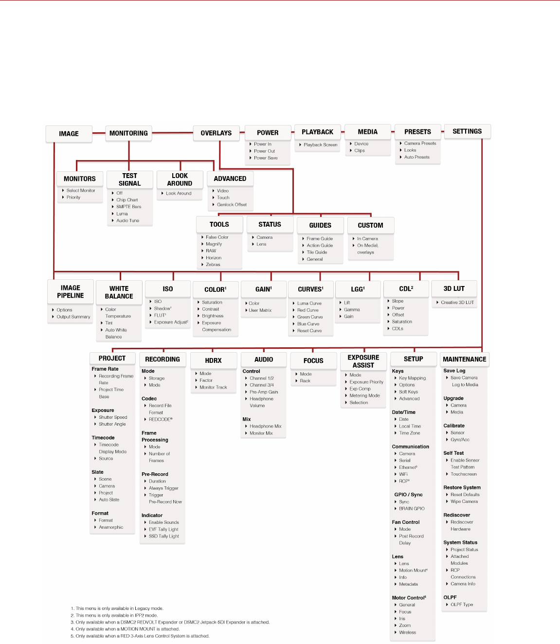
C OPYR I GHT © 2 01 9 R ED. C OM , LLC 9 55 -0 15 9_V 7. 1, R EV- G|267
EPIC-W GEMINI OPERATION GUIDE
APPENDIX F:
MENU MAP
