Redline Communications AN100UXA OFDM broadband wireless transceiver device. User Manual 70 00058 01 01 DRAFT
Redline Communications Inc. OFDM broadband wireless transceiver device. 70 00058 01 01 DRAFT
Contents
- 1. User manual
- 2. user manual
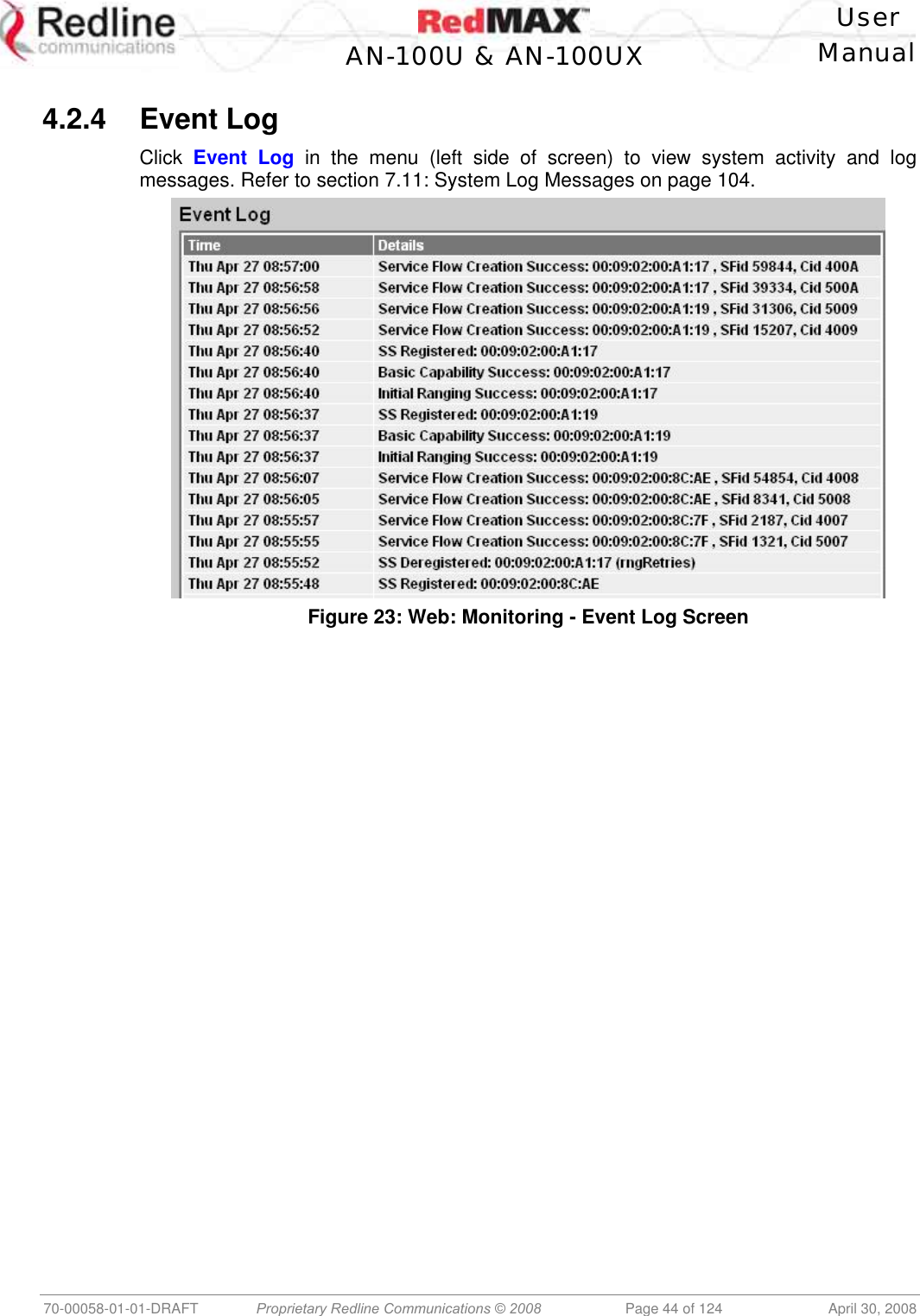
User manual

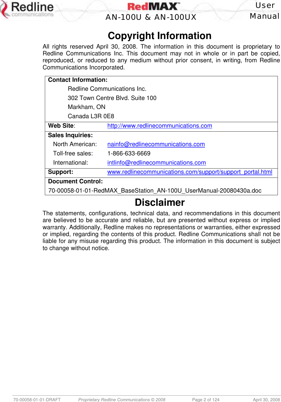
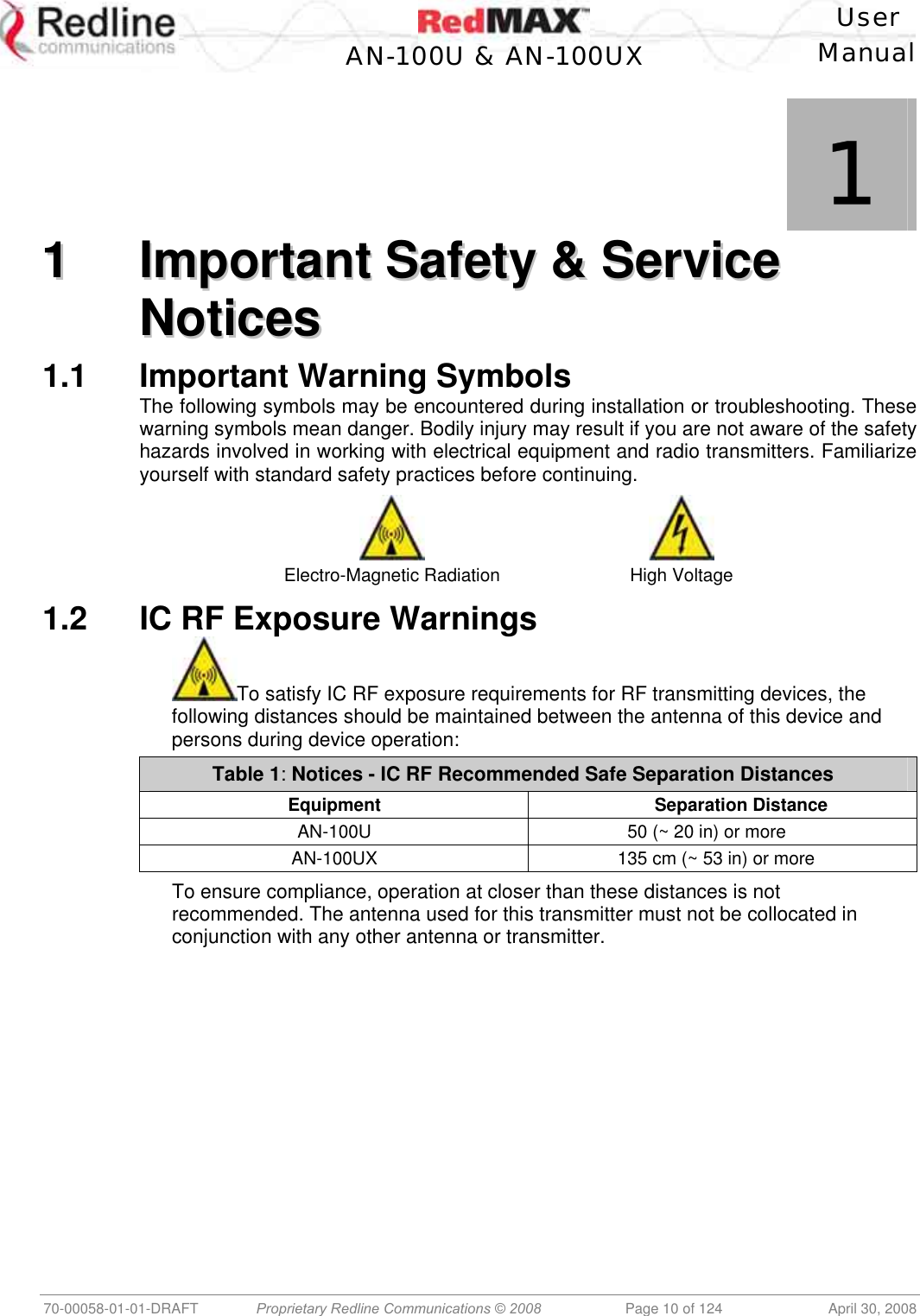
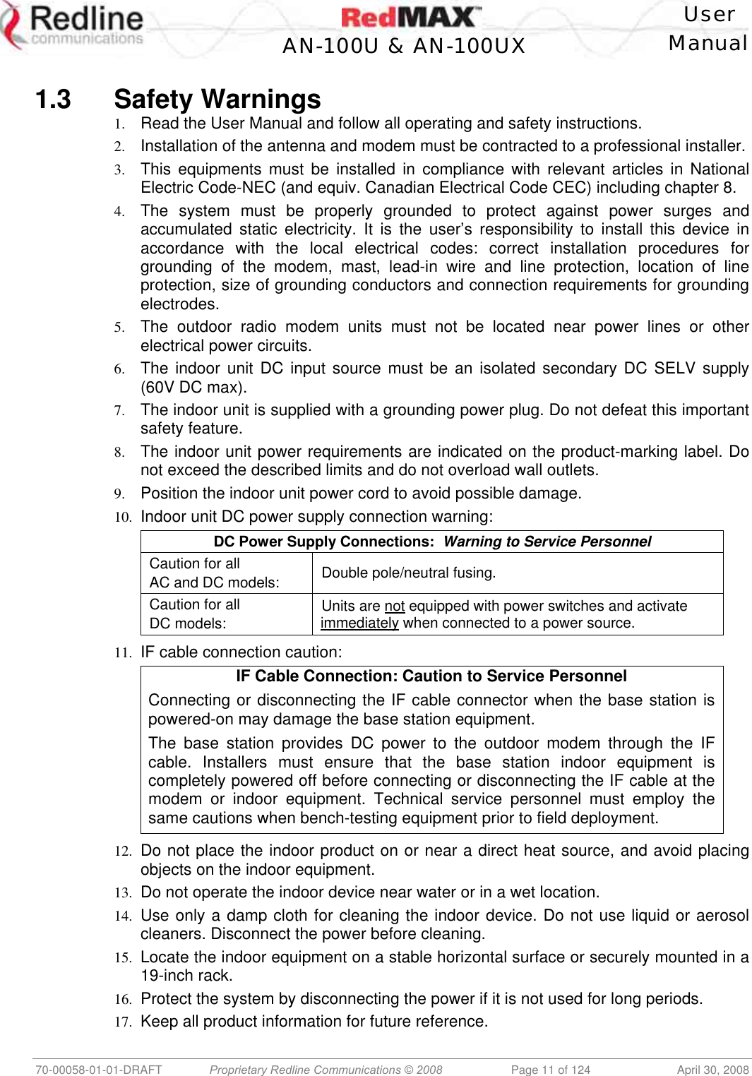
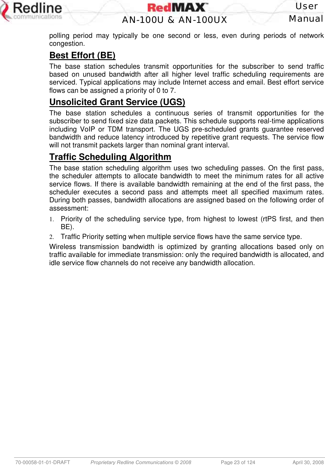
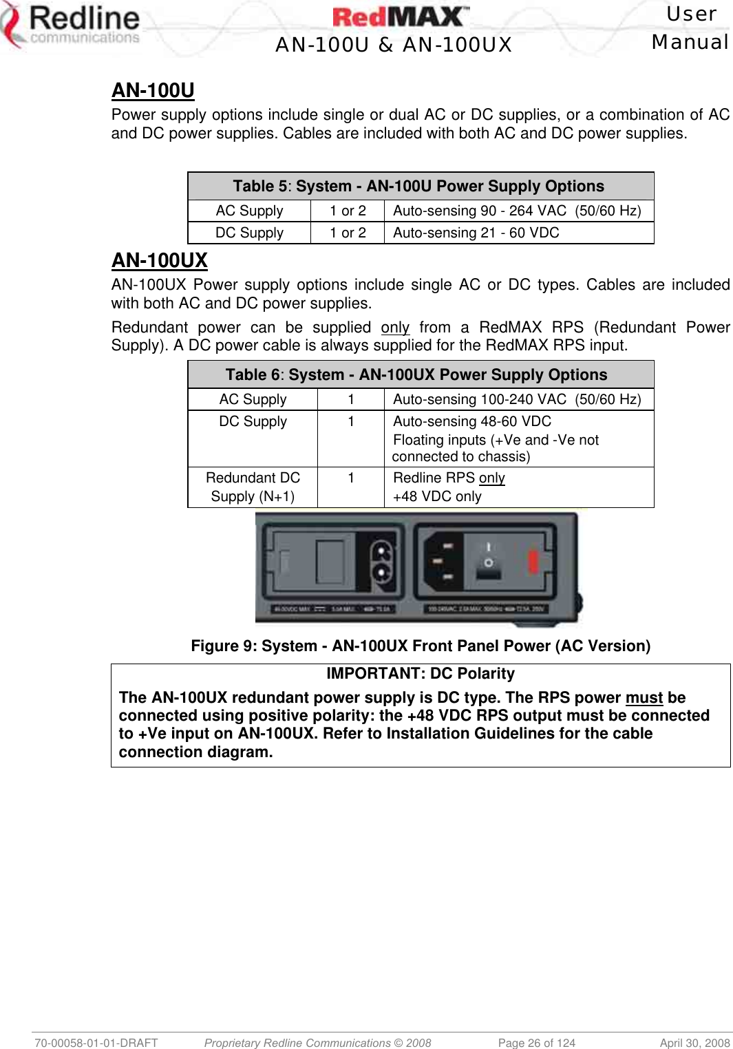
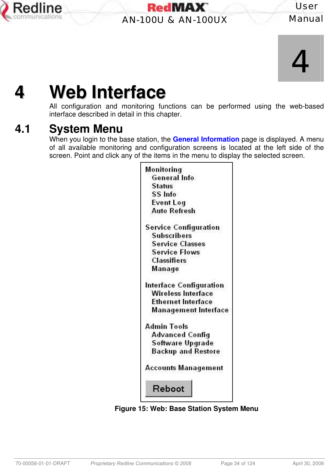
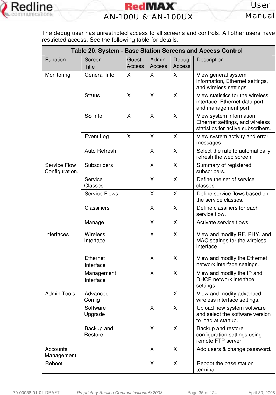
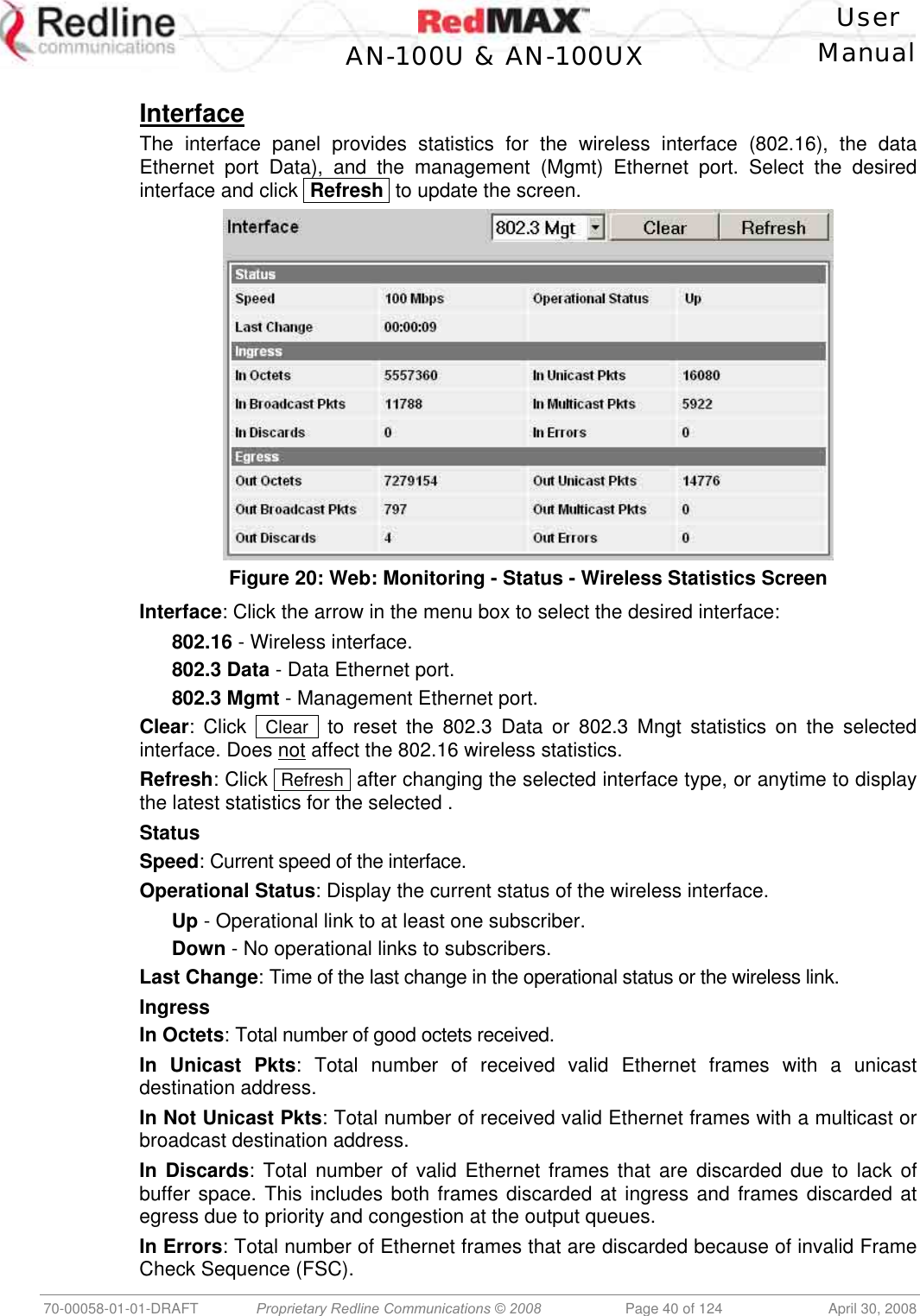
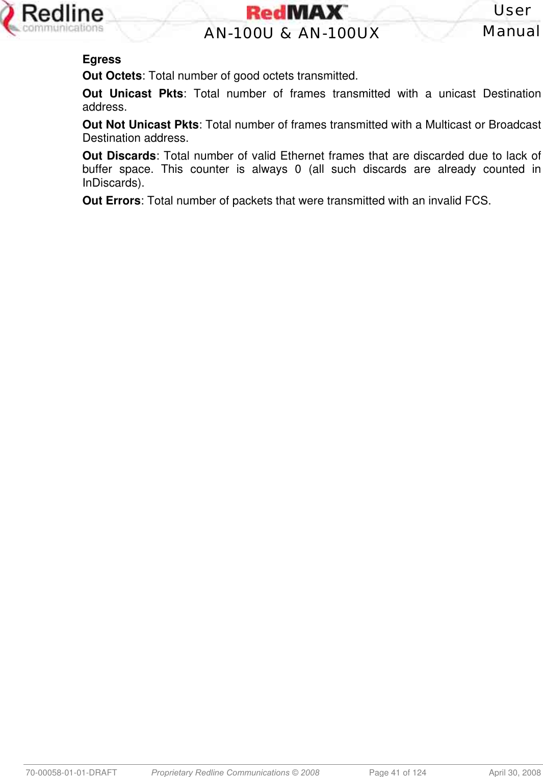
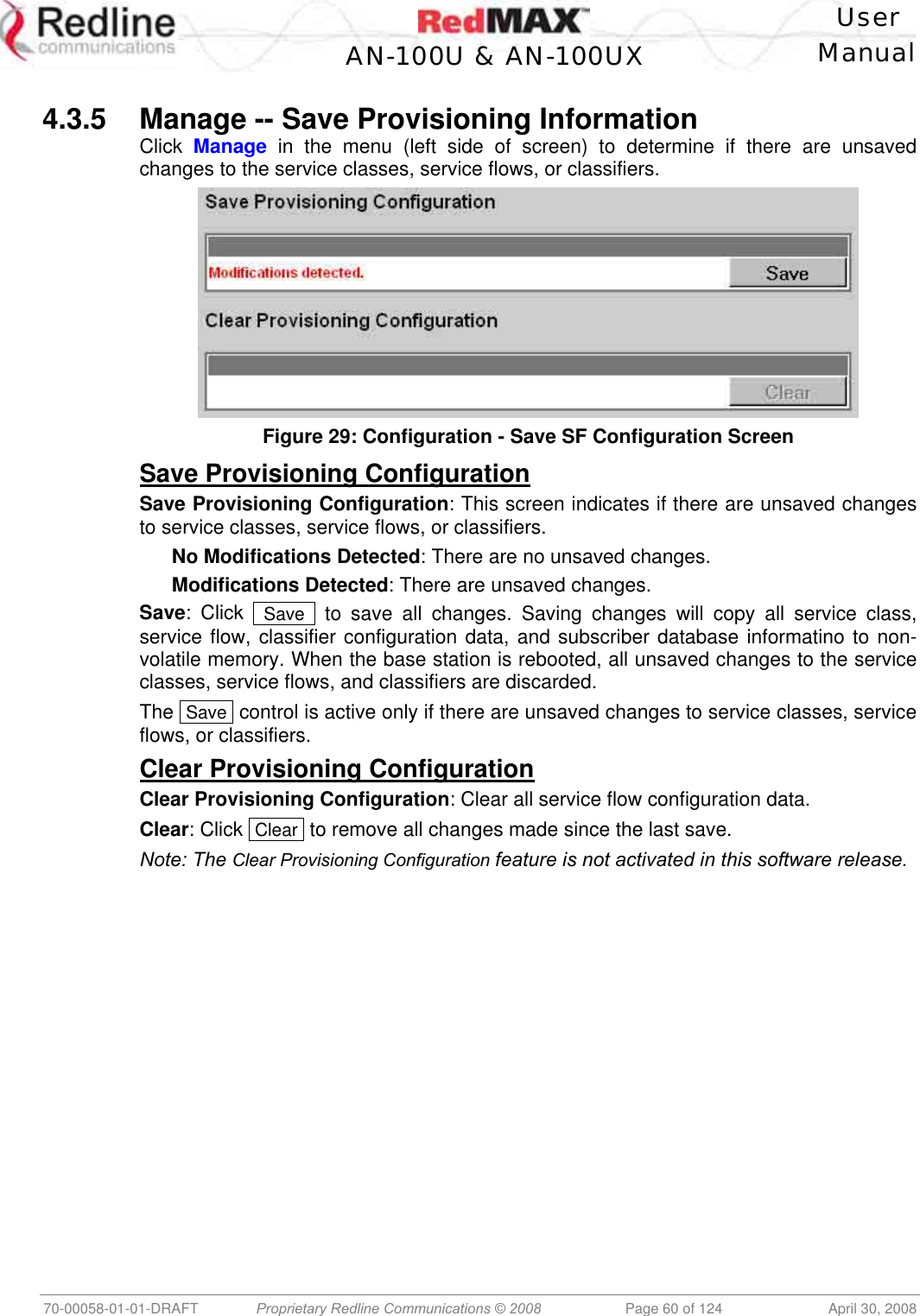
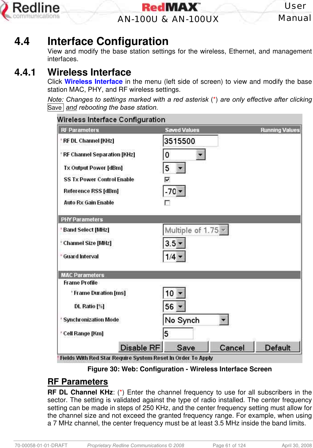
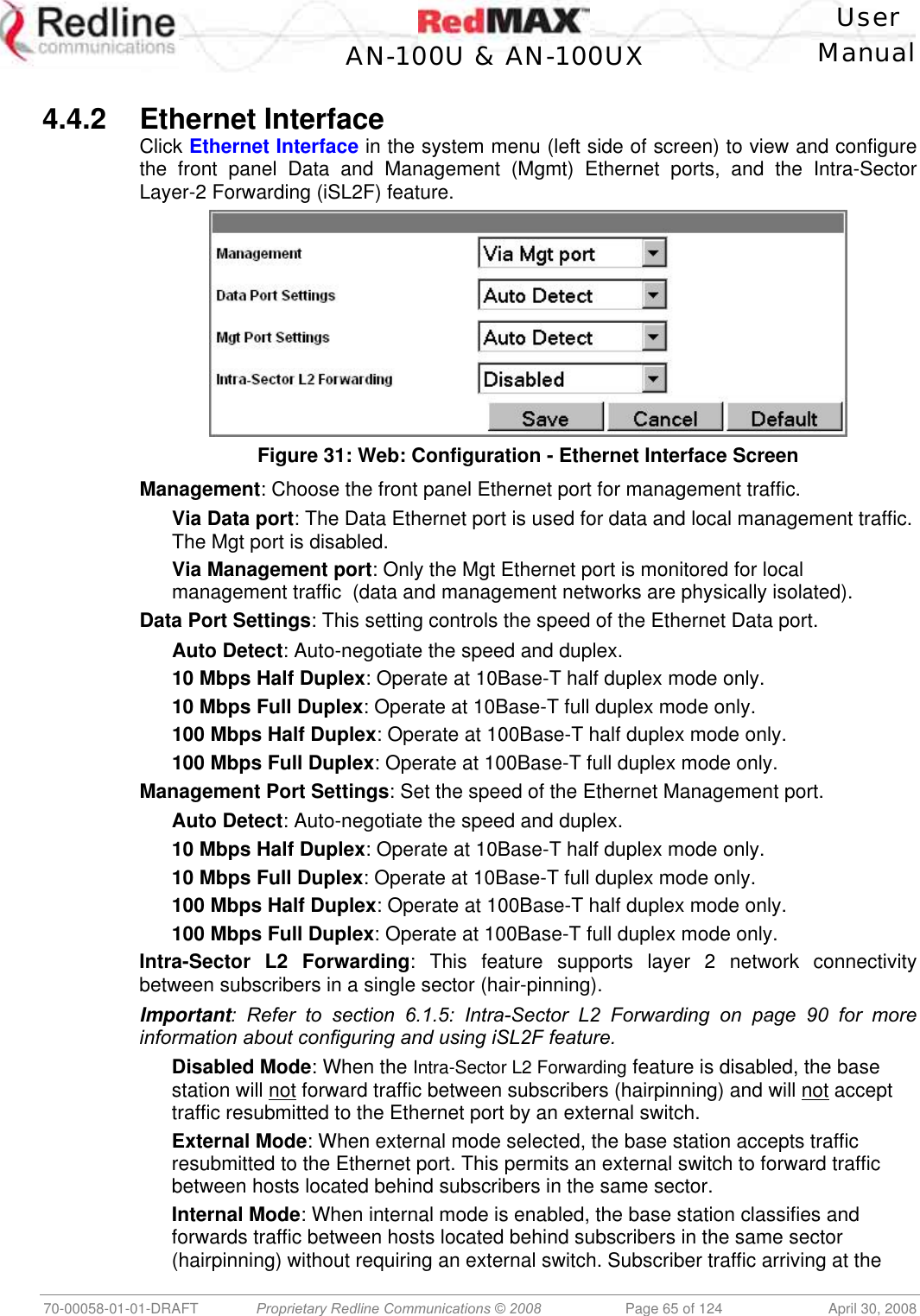
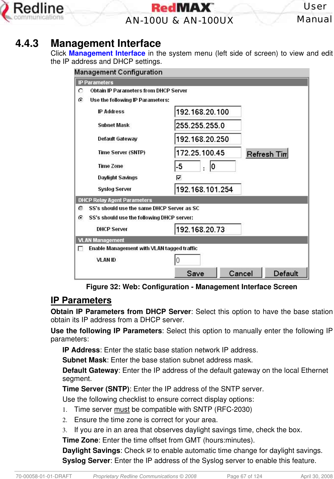
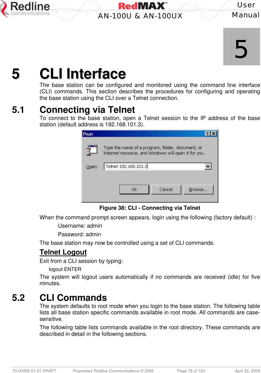
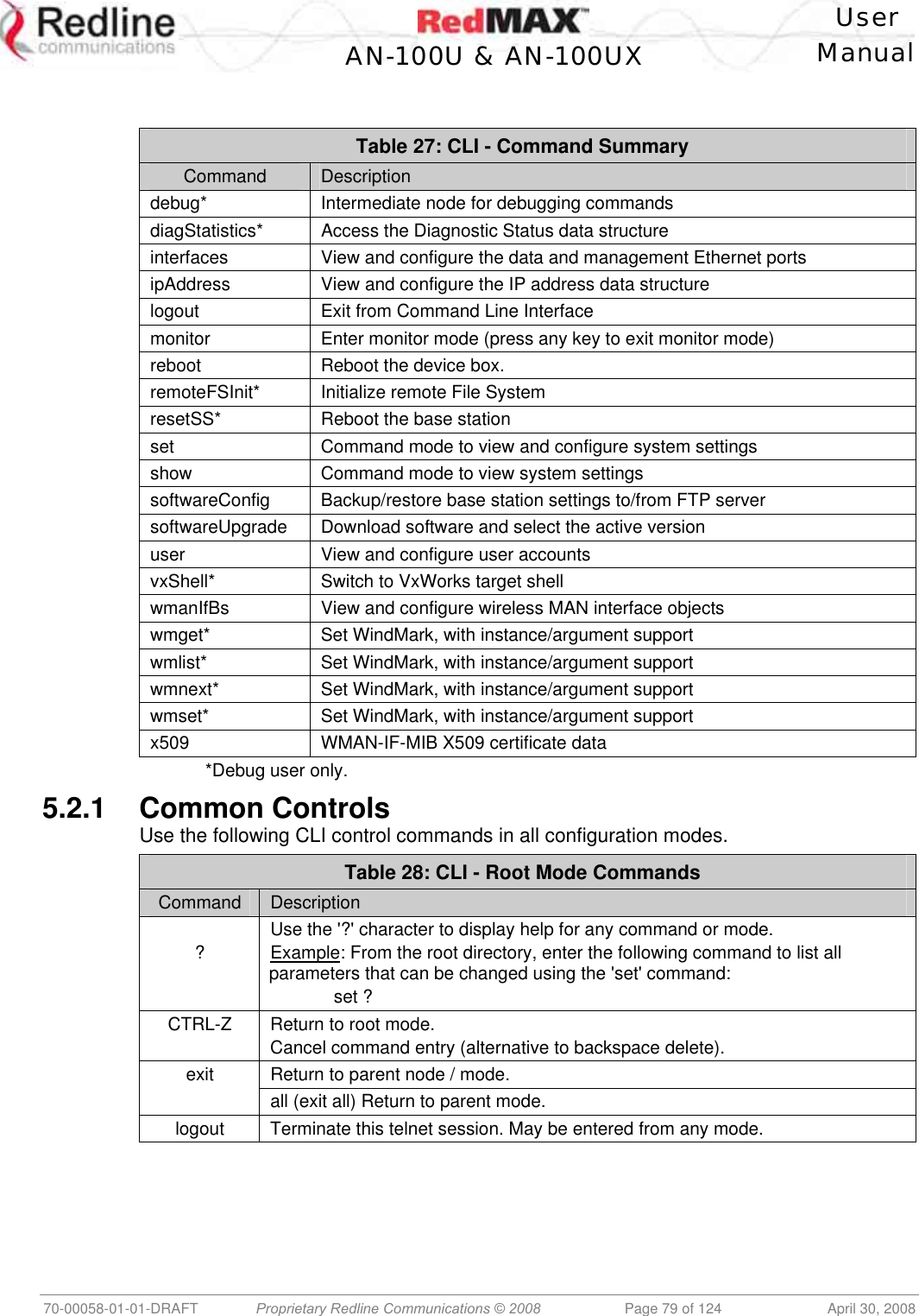
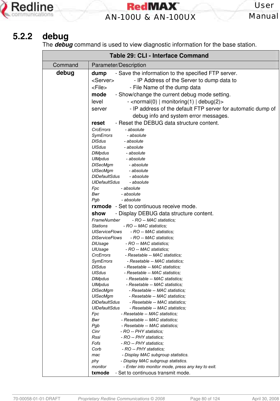
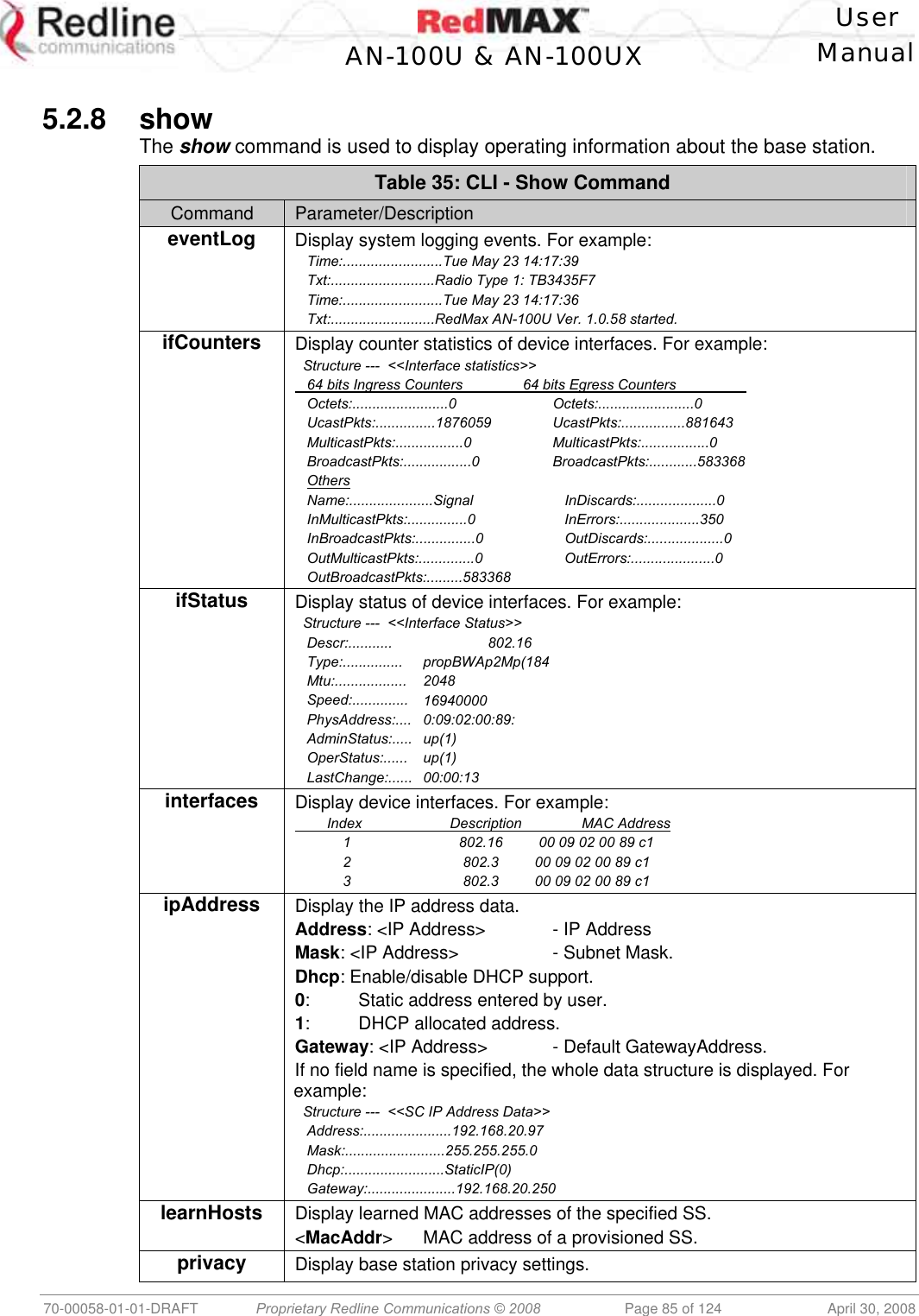
![User AN-100U & AN-100UX Manual 70-00058-01-01-DRAFT Proprietary Redline Communications © 2008 Page 38 of 124 April 30, 2008 4.2.2 Status Click Status in the system menu (left side of screen) to view status information about the wireless interface and Ethernet management interface. Values are updated according to the screen refresh rate. Figure 19: Web: Monitoring - Status - Wireless Status Screen Wireless Status CINR [dB]: Mean Carrier/(Interference + Noise) ratio. The CINR value is calculated and displayed for each automatic screen refresh. The CINR measured by the base station is based on the signal from the subscriber. Based on this value, the base station may request that the subscriber change modulation rate. Traffic Downlink [kbps]: Rate of traffic transmitted to subscribers. BW Margin Downlink [kbps]: Downlink bandwidth available that can be scheduled by the base station (based on the minimum traffic rate settings for all active service flows). CRC Errors: Number of CRC errors detected on packets received from subscribers. This counter is reset when the base station is rebooted. Note: The CRC Errors counter in the SS Info screen is reset when a subscriber is registered. Air Interface Status: Status of the base station modem: Enabled - Transceiver is operating normally. Disabled - Transceiver is disconnected, disabled, or defective. IDU Temperature [Celsius]: Internal temperature of the indoor terminal. Power Supply Status: Display the status of the power circuits. A-On - Terminal is equipped with AC circuits only. D-On - Terminal is equipped with DC circuits only. A-D - Terminal is equipped with AC and DC circuits. Active DL Service Flows: Number of currently active downlink service flows. DL SMC Rate [kbps]: Data rate for SMC channel. DL Bandwidth Usage [%]: Current usage of downlink channel. Reference RSS [dBm]: The Reference RSS setting is the target value for average Received Signal Strength (RSS) for subscribers RF signals received by the base station.](https://usermanual.wiki/Redline-Communications/AN100UXA.User-manual/User-Guide-937402-Page-38.png)
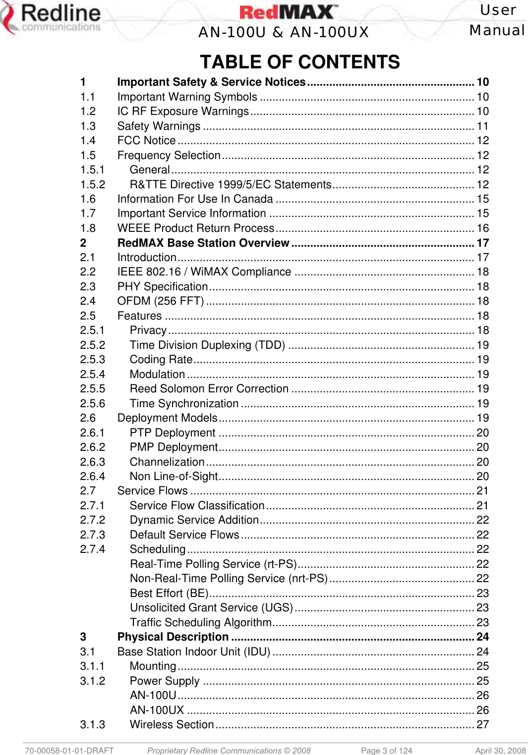
![User AN-100U & AN-100UX Manual 70-00058-01-01-DRAFT Proprietary Redline Communications © 2008 Page 39 of 124 April 30, 2008 This target value allows automatic adjustment of the subscriber Tx power for optimum performance with the minimum of RF interference. The suggested default setting for the Reference RSS value is: Channel Size Initial Setting 3.5 MHz -75 dBm 7.0 MHz -72 dBm These are the suggested initial settings; adjustments to this target value must be made based on the individual RF characteristics of each deployed sector. The RSSI value (dBm) for each subscriber can be monitored using the base station SS Info screen (Web interface). Tx power adjustments are based on a number of factors, and differences of up to 7 dB may be observed between the Reference RSS setting and measured RSSI. RF Tx Power [dBm]: Radio transmission output power level. Traffic Uplink [kbps]: Rate of traffic received from subscribers. BW Margin Uplink [kbps]: Uplink bandwidth available that can be scheduled by the base station (based on the minimum traffic rate settings for all active service flows). Registered SS's: Number of subscribers currently registered with the base station. SC Synchro Status: Status of the base station time synchronization. Refer to the RedMAX Base Station Installation Guidelines for complete details of the synchronization feature. No Synchro - Base station is not using synchronization. Master with GPS Synchro - Base station is Master and is synchronized to an external GPS clock. Master - Base station is Master and is using internal clock. Slave - Base station is Slave. Backup Master - Base station is Backup Master and will assume Master operations if Master is unavailable. ODU Temperature [Celsius]: Internal temperature of the modem. Fans Status: Display the status of the system cooling fans. oneFanOn - A single cooling fan is operating. twoFansOn - Both cooling fans are operating. Active UL Service Flows: Number of currently active uplink service flows. UL SMC Rate [kbps]: Data rate for uplink channel. UL Bandwidth Usage [%]: Current usage of uplink channel. Noise Level [dBm]: Indicates the noise level. This value is measured by sampling the radio receiver input during idle periods (base station and subscribers are not transmitting) and provides an indication of the average level of interference in the sector.](https://usermanual.wiki/Redline-Communications/AN100UXA.User-manual/User-Guide-937402-Page-39.png)
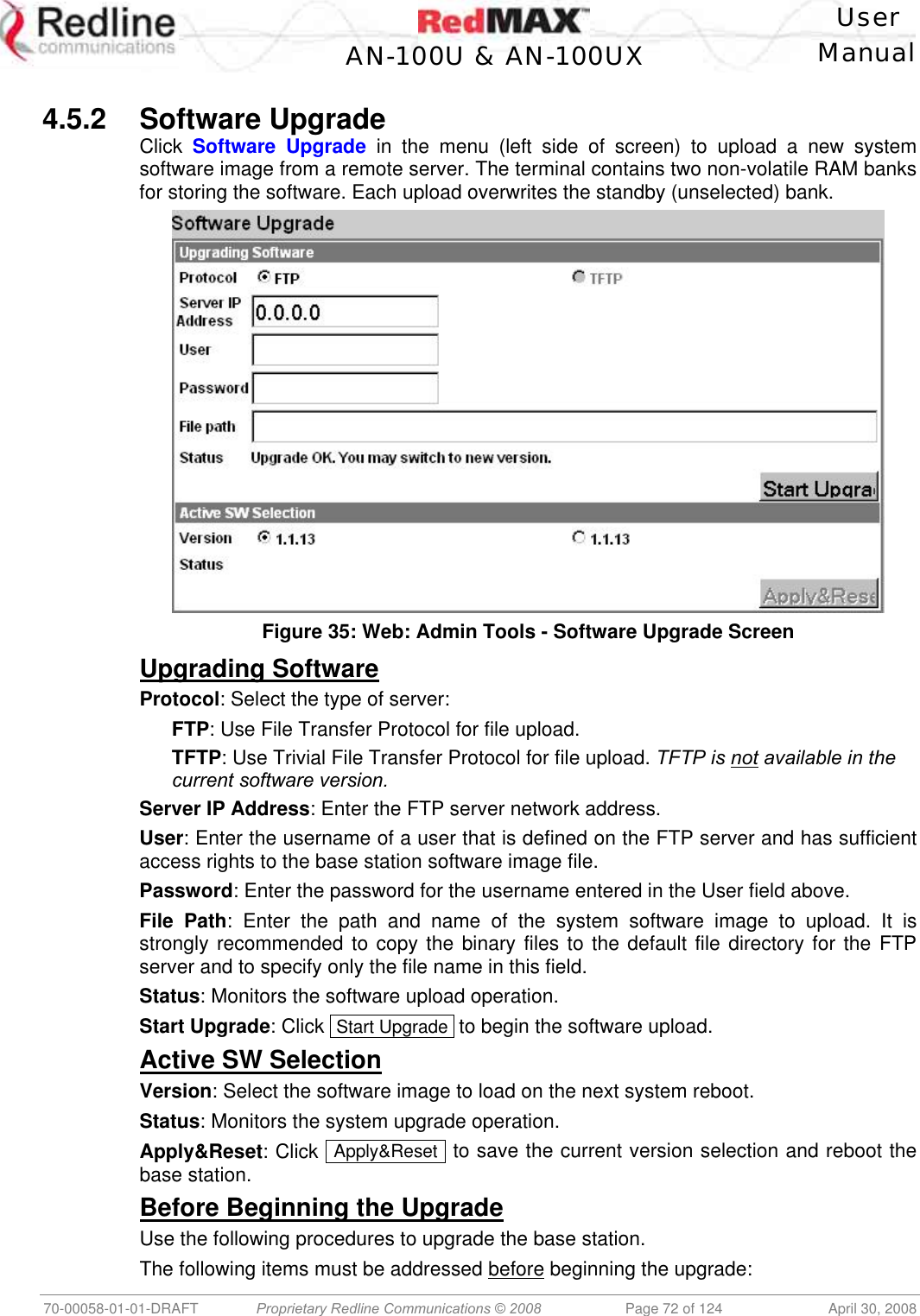
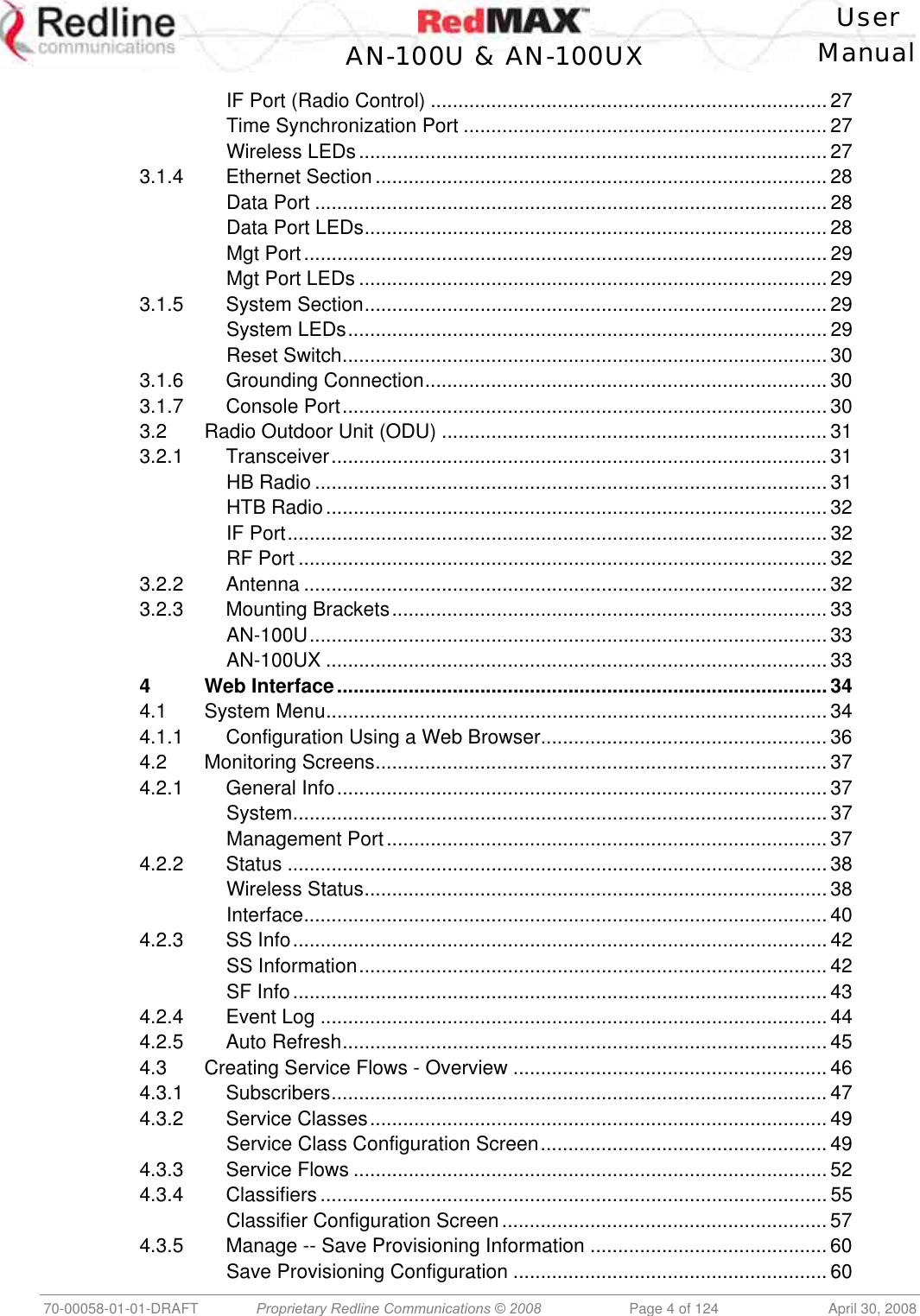
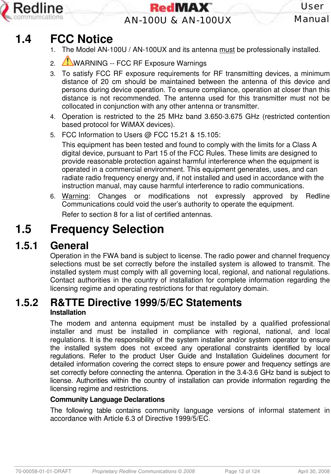
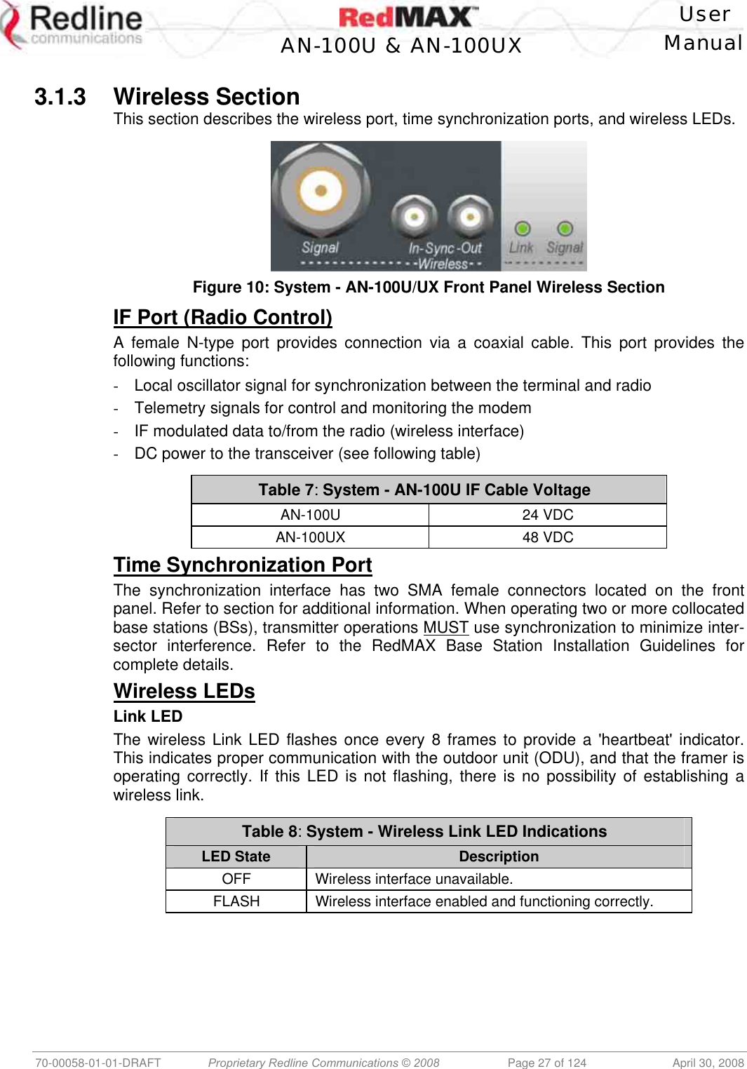
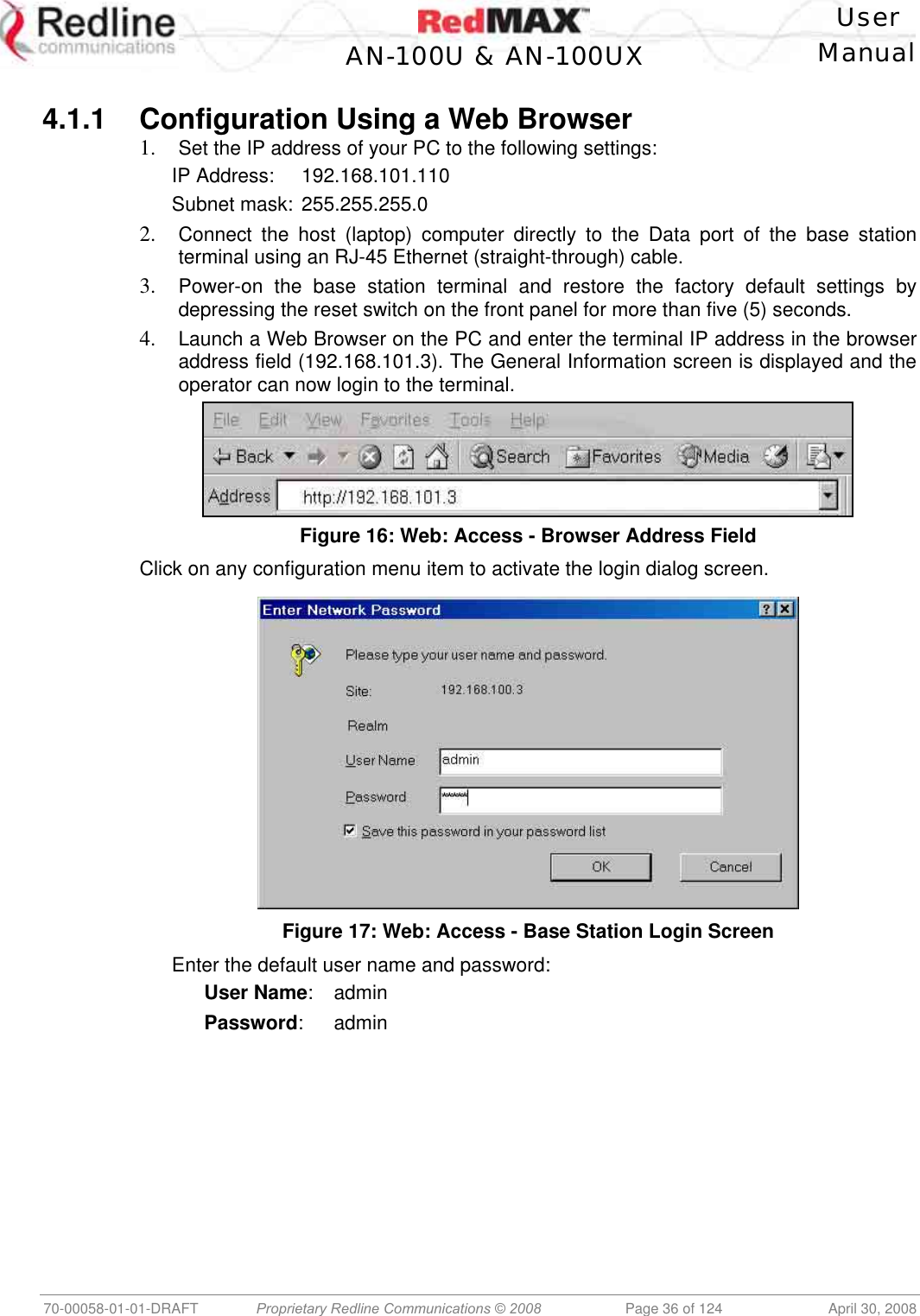
![User AN-100U & AN-100UX Manual 70-00058-01-01-DRAFT Proprietary Redline Communications © 2008 Page 73 of 124 April 30, 2008 1. You must obtain the latest base station binary files. You must copy the binary files into the default file location for the FTP server. You can not specify a 'path' in the upgrade dialog. 2. The base station performs all software upgrades using an FTP server: a) The FTP server must be located on the network connected to an active Ethernet port (Data or Mgmt) on the base station. b) The FTP server must have a user defined as follows: username: target password: secret Upgrade Base Station 1. Start a Web browser session to the base station and login. The factory default settings are as follows: Login: admin Password: admin 2. Click Software Upgrade in the left-hand menu and make the following settings: Protocol: FTP Server IP address: [enter address of FTP server] User: target Password: secret File Path: [Enter binary file name -- including .bin extension] 3. Click Upgrade and wait for the base station to download and save the binary file. This process may take a few minutes. Progress is indicated in the Status field. The Status Screen displays 'Update OK' when the upgrade is complete. 4. In the Software Upgrade screen, Select the new version and click Apply&Reset to activate the new software. Click Yes in the confirmation dialog.](https://usermanual.wiki/Redline-Communications/AN100UXA.User-manual/User-Guide-937402-Page-73.png)
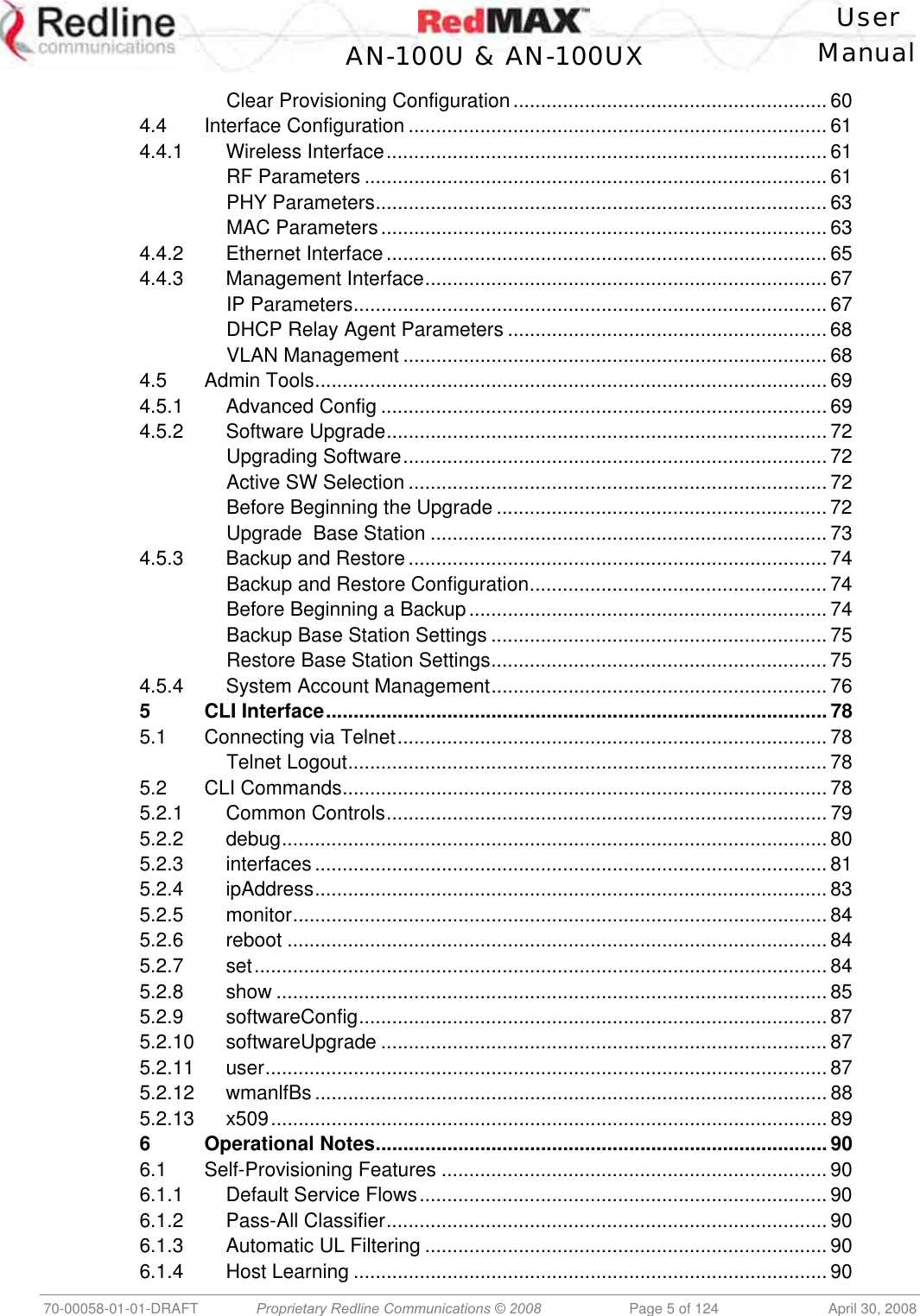
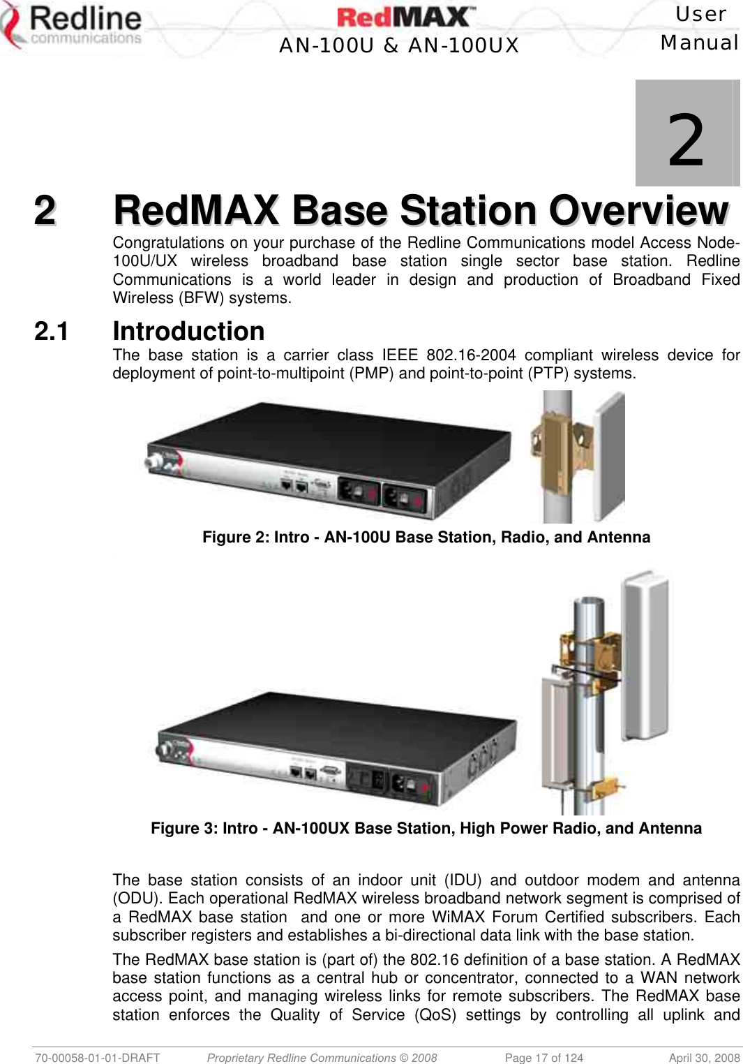
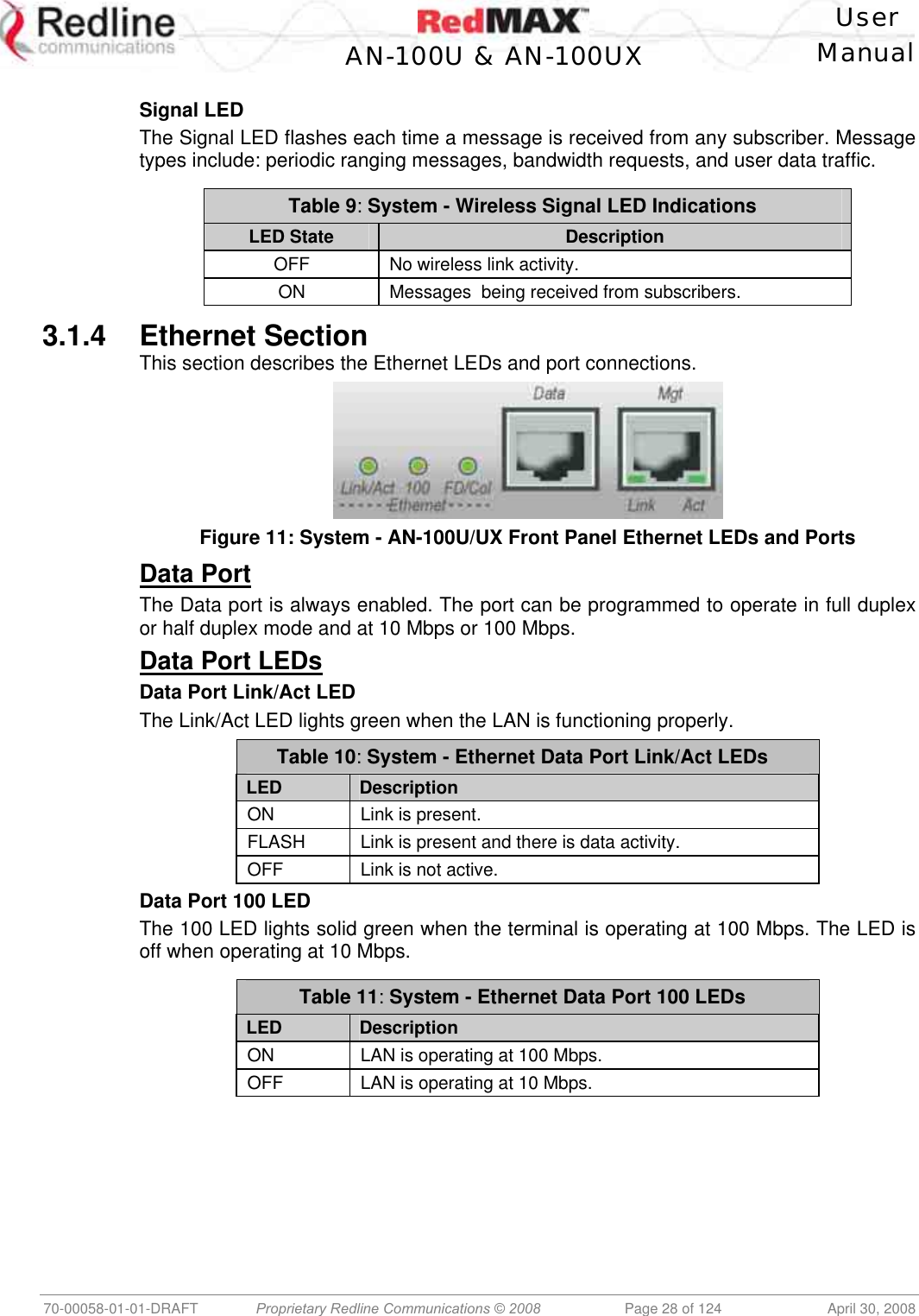
![User AN-100U & AN-100UX Manual 70-00058-01-01-DRAFT Proprietary Redline Communications © 2008 Page 93 of 124 April 30, 2008 The authentication process ensures the subscriber modem is an authentic device and not a rogue that was brought into the wireless sector area. For authentication the devices use X.509 digital certificates [IETF RFC 3280] together with RSA public-key encryption algorithm. At the end of the authentication, process the device has a shared key with its peer known as AK (Authentication Key). This Key is used to derive the TEK. Management messages between base station and subscriber modem are protected with a HMAC digest that ensures the data was not altered over the air in any way. The authenticity of the CA's signature, and whether the CA can be trusted, can be determined by examining its certificate in turn. This chain must however end somewhere, and it does so at the root certificate, so called as it is at the root of a tree structure. Root certificates are implicitly trusted. Redline Root CA certificate is issued by Verisign. It can be uses to validate the certificates of the subscriber modem and cannot be used to validate the certificates supplied by another vendor. Authentication Using Digital Certificates The entire authentication process is performed inside the base station and it does not require external AAA servers (e.g. RADIUS, TACCACS, LDAP, etc). Sixty-four Kilobytes (64 KB) of memory is reserved for X509 Root CA certificates. A root certificate allows the validation of subscriber modem certificates. Validation process implies a check of the certificates against the information stored on the base station. The result of this check is a truth value based on which the base station will allow the subscriber to join the network. There are two scenarios: 1. Base station can skip the validation of the certificates sent from subscriber and performs only a basic test to ensure is properly encoded. 2. Base station checks the digital signature with the information stored on the board. To switch between the two scenarios the operator modifies the field TrustAll under "privacy" group. 6.2.2 Configuring Privacy This section describes the CLI commands for Privacy sublayer functions. Settings for privacy modules are defined under "privacy" group. The values set by the user are taken into account only after a system reboot, even though the values are stored into NVRAM memory immediately. The privacy module on the base station always running, while the subscriber modem can be enabled or disabled. X509 Root CA Certificates Each subscriber modem shipped from the factory comes with two X509 certificates - subscriber modem certificate and CA certificate. The subscriber modem certificate is unique per subscriber modem sends the certificates to the base station during network entry procedure in order to authenticate itself. The base station verifies the certificates are valid and allows or denies the subscriber request to join the network. Base Station Privacy Settings The AK lifetime specifies the period the subscriber is authenticated with the base station, and TEK specifies the period the traffic key is valid. Changes to these parameters require a reboot. The two keys are replaced at regular time intervals as specified by their corresponding lifetimes. The operator can also specify to trust all subscriber certificates or to validate each subscriber based on stored root certificates. There are two modes: Operational Mode: The base station uses the 802.16 standard default values. Test Mode: Used only for testing the standard certification process.](https://usermanual.wiki/Redline-Communications/AN100UXA.User-manual/User-Guide-937402-Page-93.png)
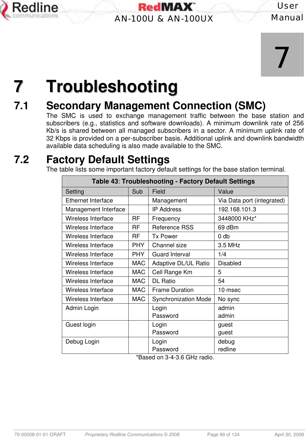
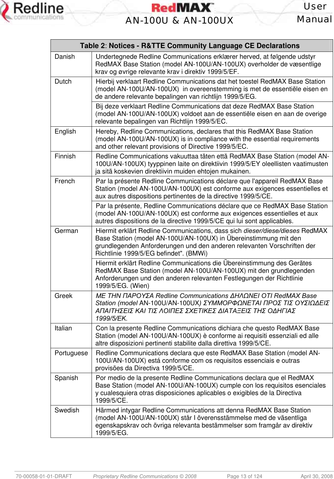
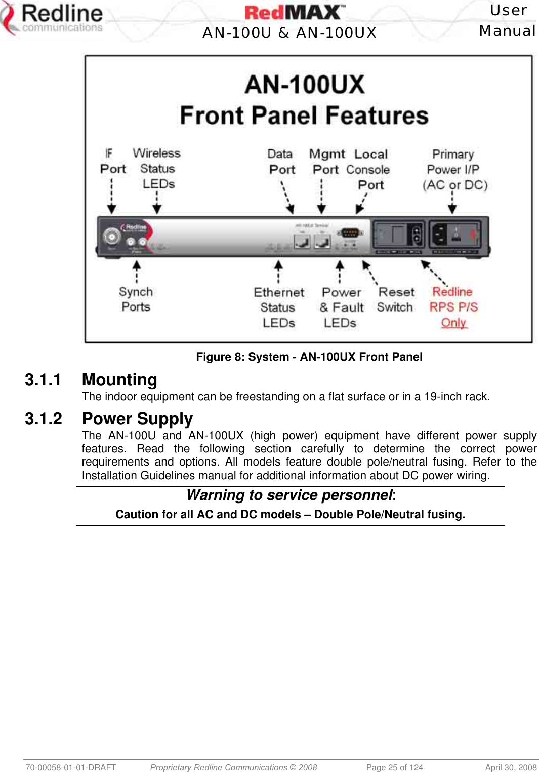
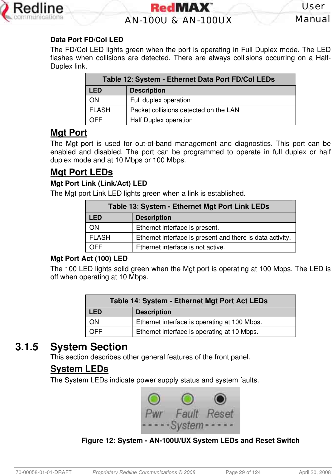
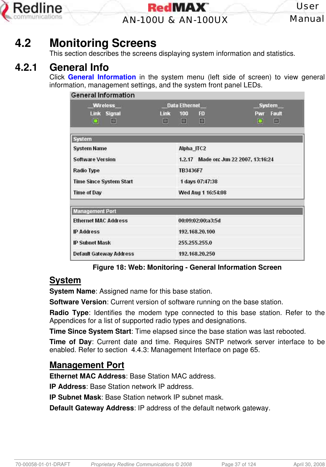
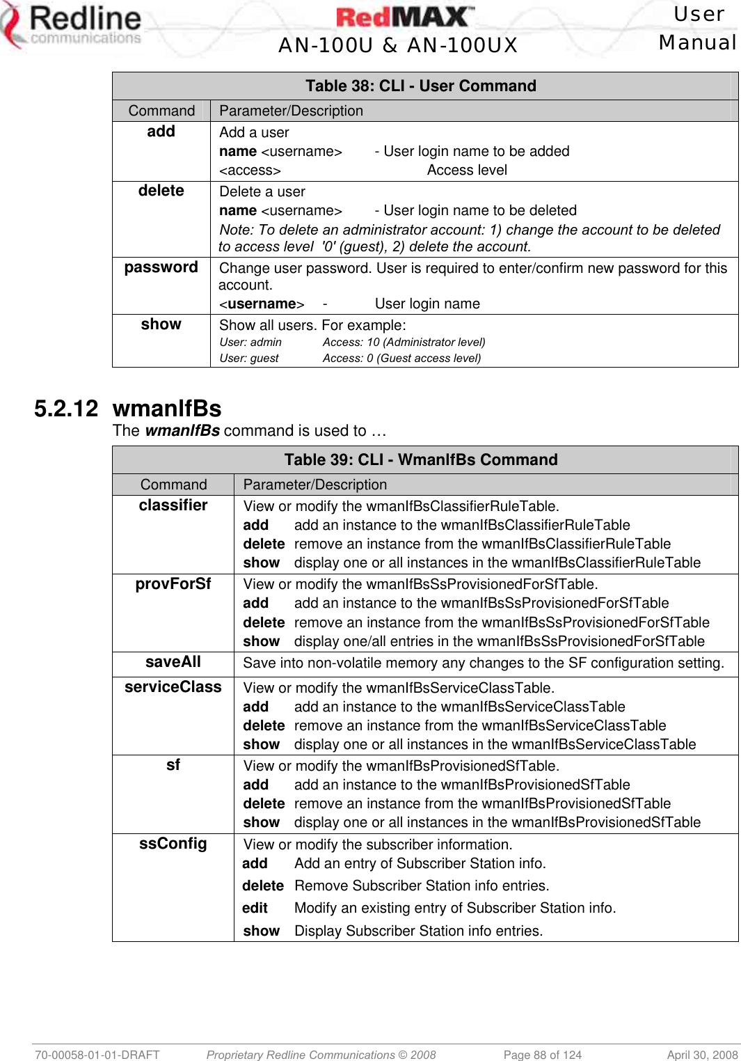
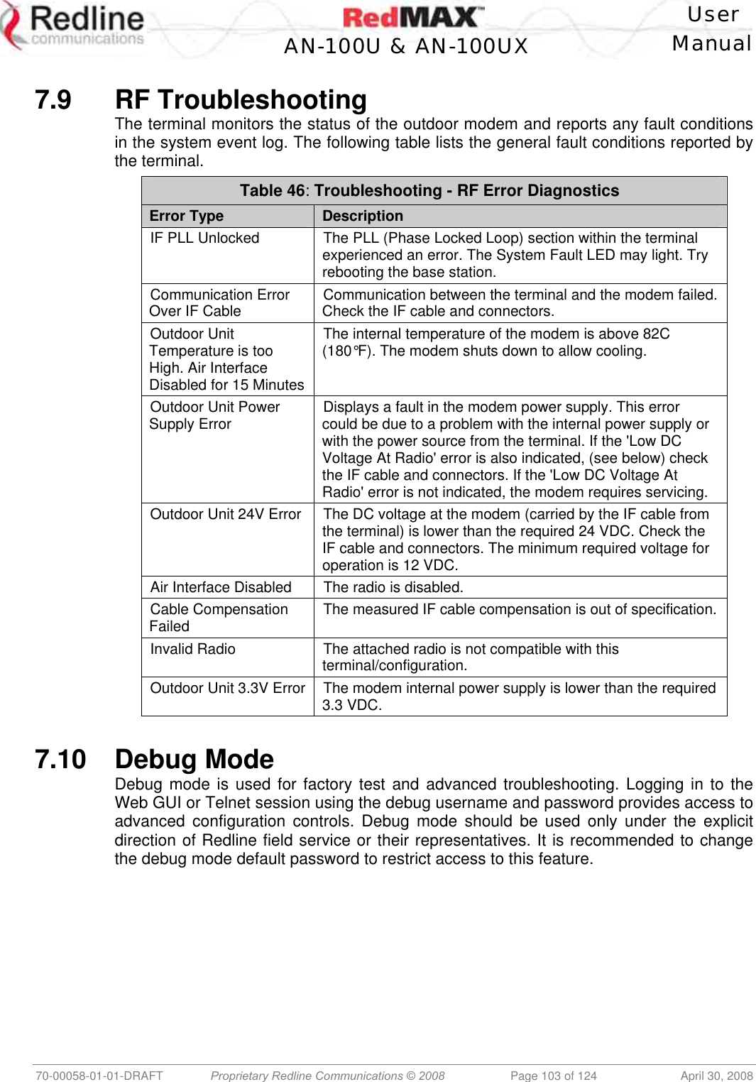
![User AN-100U & AN-100UX Manual 70-00058-01-01-DRAFT Proprietary Redline Communications © 2008 Page 100 of 124 April 30, 2008 7.3 Front Panel Diagnostics Figure 42: Diagnostics: Base Station Front Panel View 7.3.1 System LEDs The front panel of the terminal includes a number of LEDs to monitor operation of the system and assist troubleshooting. Refer to section 3: Physical Description on page 24. 7.3.2 Console Port The front panel includes the Console port. Use the CLI commands to interrogate the base station status and program most system settings. 7.3.3 System Reset Switch Throughout this section, reference is made to the reset switch, which is a micro-switch recessed in the front panel in the system block. Use a small narrow object, such as a paper clip, to access the switch. Depressing the reset switch for less than five seconds activates a short-reset (equivalent to power-cycle). Statistical values are reset. Depressing the front panel reset switch for more than five seconds activates a long-reset. A long-reset reloads the factory defaults for the IP Address, IP subnet mask, password, and statistical values are reset. 7.4 Detecting Channel Interference at Startup Following a power-cycle or reboot, the base station monitors the RF Channel to detect interference on the uplink channel. The transceiver is set to receive mode and the PHY is programmed to receive a long preamble from a WiMAX base station. If no preamble is detected during the one-second interval, the channel is considered free of interference from other WiMAX equipment. If a long preamble is received, the base station continues to monitors the channel for an additional three seconds. If an 802.16d DL-Map is received, the following message will be entered into the event log: WARNING: RF Channel Conflict with [BS Id] This message in the event log indicates that another base station has been detected using the following RF-PHY characteristics: - Same DL channel frequency as the UL channel frequency of this SC - Same Cyclic Prefix - Same channel size (i.e., 7 MHz) If a long preamble was received, but no DL-Map was detected, the following message will be entered into the event log: WARNING: Unknown Interference was detected on the UL channel This second message does not necessarily indicate interference from another base station, and may be the result of cross-interference from subscribe stations.](https://usermanual.wiki/Redline-Communications/AN100UXA.User-manual/User-Guide-937402-Page-100.png)
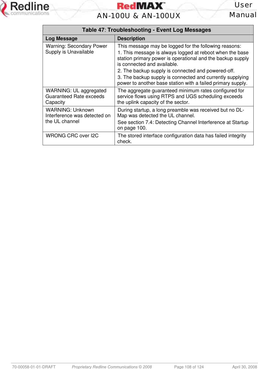
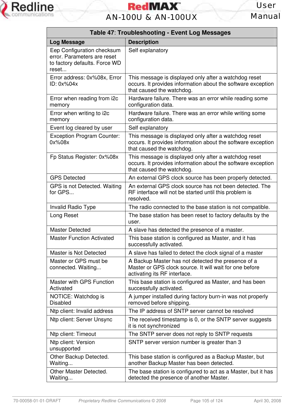
![User AN-100U & AN-100UX Manual 70-00058-01-01-DRAFT Proprietary Redline Communications © 2008 Page 104 of 124 April 30, 2008 7.11 System Log Messages Table 47: Troubleshooting - Event Log Messages Log Message Description Access Address : 0x%08x This message is displayed only after a watchdog reset occurs. It provides information about the software exception that caused the watchdog. Air Interface is Disabled The RF interface has been disabled by the user. Air Interface is Enabled The RF interface has been enabled by the user. Another Upgrade operation is currently running. Skip SNMP[CLI,WEB] upgrade The user has tried to initiate an upgrade while another upgrade is already in progress. The command has been ignored. Another Upgrade operation is currently running. Skip SNMP[CLI,WEB] synchronization The user has tried to synchronize the active and alternate images while a software upgrade is in progress. The command has been ignored. Another Upgrade operation is currently running. Skip SNMP[CLI,WEB] backup The user has tried to backup the active image to the alternate while a software upgrade is in progress. The command has been ignored. Another Upgrade operation is currently running. Skip SNMP[CLI,WEB] restore The user has tried to apply a configuration file to either the active or alternate images while a software upgrade is in progress. The command has been ignored. Another Upgrade operation is currently running. Skip switchover The user has tried to switch software versions while an upgrade is in progress. The command has been ignored. Backup Detected This base station is configured as Master, and it has detected the presence of a Backup Master Backup Function Activated This base station is configured as a Backup Master, and has been successfully activated Cable Compensation Ok. Value = [v] The attenuation of the IF cable is within operating parameters. Cause Register: 0x%08x This message is displayed only after a watchdog reset occurs. It provides information about the software exception that caused the watchdog. CRITICAL: Cable Compensation Failed The attenuation of the IF cable to the ODU is too high. CRITICAL: IF Cable Disconnected The IF cable between the base station IDU and ODU has been disconnected. CRITICAL: IF PLL Error The IF chain has encountered a PLL error. Communication with the ODU has been interrupted. CRITICAL: LO[X] Error There has been a hardware problem with Local Oscillator [X]. CRITICAL: ODU Temperature is too High The operating temperature of the base station ODU is too high to continue operation. The IDU will temporarily suspend operation to avoid damage. CRITICAL: Radio Reference Frequency Error There has been a hardware problem with the synchronization of the ODU’s reference frequency. CRITICAL: Rx IF PLL Error The IF chain has encountered a PLL error. Communication with the ODU has been interrupted.](https://usermanual.wiki/Redline-Communications/AN100UXA.User-manual/User-Guide-937402-Page-104.png)
![User AN-100U & AN-100UX Manual 70-00058-01-01-DRAFT Proprietary Redline Communications © 2008 Page 106 of 124 April 30, 2008 Table 47: Troubleshooting - Event Log Messages Log Message Description P1 Watchdog Reset The P1 processor has encountered an exception, and has prompted a reboot of the base station P2 Watchdog Reset The P2 processor has encountered an exception, and has prompted a reboot of the base station P2-Task: %#x \"%s\ This message is displayed only after a watchdog reset occurs. It provides information about the software exception that caused the watchdog. Parameters are reset to factory defaults This message appears after the user has initiated a long-reset to factory defaults Power Supply [X] is On Where X is either A or B. This signifies that the relevant power supply has been detected and is properly supplying power to the base station Primary Power Supply is On The base station primary power supply (AC or DC) is operational. Message is logged only when system has been operating on backup power. Radio Type [XX]: TBXXXXFX This message is simply a confirmation of the type of radio connected to the IDU. It should match with the radio type printed on the ODU’s sticker. RedMax base station Ver. X.X.X started System startup message. Reference Clock Calibration Done The reference clock calibration procedure initiated by the user has been completed. Reference Clock Calibration Failed The reference clock calibration procedure initiated by the user has failed. Restore configuration into active image The user-provided configuration file has been applied to the active image Restore configuration into alternate image The user-provided configuration file has been applied to the alternate (non-active) image RF capabilities are changed. Check RF and PHY parameters and activate again the RF interface Self explanatory Secondary Power Supply is Available The backup supply is connected and available if the base station primary supply fails. Status Register: 0x%08x This message is displayed only after a watchdog reset occurs. It provides information about the software exception that caused the watchdog. Synchronization Failed. Waiting for Synchronization Signal... A base station configured as Slave has detected the Master on reboot, but synchronization failed. It will wait and try again. Synchronization Lost A slave has previously synchronized with a Master, but since lost the signal and drifted out of phase. Synchronization of alternate completed successfully Software image and configuration have been applied to the alternate image, overwriting its previous contents. Synchronization of configurations not possible The synchronization of software and configuration from the active image to the alternate has failed. Synchronization Ok Synchronization with a Master or Backup Master was successful.](https://usermanual.wiki/Redline-Communications/AN100UXA.User-manual/User-Guide-937402-Page-106.png)
![User AN-100U & AN-100UX Manual 70-00058-01-01-DRAFT Proprietary Redline Communications © 2008 Page 107 of 124 April 30, 2008 Table 47: Troubleshooting - Event Log Messages Log Message Description Synchronization Signal Detected A Slave has detected the clock signal of a Master. Synchronization Signal not Detected A slave has previously synchronized with a Master, but has since lost the signal. Synchronization Signal not Detected. Waiting... A base station configured as Slave cannot detect the synchronization Master. Synchronization with Backup Failed This base station is configured as Master. It has recently rebooted, detected the presence of a Backup Master, but it has failed to resume control of the base station’s clock. Synchronization with Backup Ok This base station is configured as Master. It has recently rebooted, detected the presence of a Backup Master, and successfully resumed control of the base station’s clock. Synchronization with GPS is Lost Synchronization with a previously detected external clock source has been lost Synchronization with GPS Ok Synchronization with an external GPS clock has been successfully completed. Synchronization with Master is Lost A Backup Master has previously detected the presence of a master clock signal, and synchronized. It has since lost this signal. Synchronization with Master Ok A slave has successfully synchronized with a master’s clock signal WARNING: Clock Offset Close to End of Scale The reference clock calibration procedure initiated by the user has been completed, but the clock offset is at the boundaries of the base station’s capabilities WARNING: DL aggregated Guaranteed Rate exceeds Capacity The aggregate guaranteed minimum rates configured for service flows using RTPS and UGS scheduling exceeds the downlink capacity of the sector. WARNING: Indoor Unit Temperature > 65 Celsius The base station indoor unit has exceeded the recommended operating temperature. WARNING: ODU Temperature is [c] Celsius The operating temperature of the base station ODU is nearing the limit of its operating temperature. No action is taken. WARNING: Power Supply [X] is Off Where X is either A or B. This signifies that the relevant power supply has been detected, but it is not supplying power to the base station. Warning: Primary Power Supply is Off The base station primary power supply (AC or DC) is powered-off or failed (using backup power supply). WARNING: RF Channel Conflict with [BS Id] During startup, a long preamble and DL-Map were both detected on the UL channel. See section 7.4: Detecting Channel Interference at Startup on page 100. Warning: Secondary Power Supply is Disconnected” The backup supply is not connected to the base station.](https://usermanual.wiki/Redline-Communications/AN100UXA.User-manual/User-Guide-937402-Page-107.png)