Redline Communications AN80IE OFDM broadband wireless transceiver device. User Manual 70 00072 01 07
Redline Communications Inc. OFDM broadband wireless transceiver device. 70 00072 01 07
Contents
- 1. an80i manual update
- 2. user manual
an80i manual update
70-00072-01-07 Proprietary Redline Communications © 2008 Page 1 of 106 Sept 18, 2008
&
AN-80i System
PTP & PMP
User Manual
& User
AN-80i
Manual
70-00072-01-07 Proprietary Redline Communications © 2008 Page 2 of 106 Sept 18, 2008
Copyright Information
All rights reserved Sept 18, 2008. The information in this document is proprietary to
Redline Communications Inc. This document may not in whole or in part be copied,
reproduced, or reduced to any medium without prior consent, in writing, from Redline
Communications Incorporated.
Contact Information:
Redline Communications Inc.
302 Town Centre Blvd. Suite 100
Markham, ON
Canada L3R 0E8
Web site: http://www.redlinecommunications.com
Sales Inquiries:
North American nainfo@redlinecommunications.com
Toll-free sales 1-866-633-6669
International intlinfo@redlinecommunications.com
Support: www.redlinecommunications.com/support/support_portal.html
Document Control:
70-00072-01-06-AN-80i_User_Manual-20080918c.doc
Disclaimer
The statements, configurations, technical data, and recommendations in this document
are believed to be accurate and reliable, but are presented without express or implied
warranty. Additionally, Redline makes no representations or warranties, either expressed
or implied, regarding the contents of this product. Redline Communications shall not be
liable for any misuse regarding this product. The information in this document is subject
to change without notice.

& User
AN-80i
Manual
70-00072-01-07 Proprietary Redline Communications © 2008 Page 3 of 106 Sept 18, 2008
TABLE OF CONTENTS
1 Important Safety & Service Notices....................................................... 9
1.1 Safety Warnings ........................................................................................ 9
1.2 Important Warning Symbols .................................................................... 10
1.3 Important Service Information ................................................................. 10
1.4 Lightning Protection................................................................................. 10
1.5 Deployment in the USA -- FCC Notices .................................................. 11
1.5.1 FCC & IC Notice .................................................................................. 11
1.5.2 Installation and Operation.................................................................... 12
1.5.3 FCC Power Settings ............................................................................ 12
1.6 UL Information......................................................................................... 12
1.7 Product Information ................................................................................. 13
2 System Overview................................................................................... 14
2.1 Ethernet Port ........................................................................................... 15
2.2 RF Port .................................................................................................... 15
2.3 Mounting Brackets................................................................................... 15
2.4 Grounding Connection ............................................................................ 15
2.5 Indoor Power Block (PoE Power Adapter) .............................................. 16
2.5.1 AC Power Adapter............................................................................... 16
2.5.2 DC Power Adapter............................................................................... 16
2.6 Antenna Alignment .................................................................................. 17
2.6.1 Web Page Alignment........................................................................... 17
2.6.2 Audible Alignment................................................................................ 17
3 Web Interface - PTP............................................................................... 18
3.1 System Login........................................................................................... 18
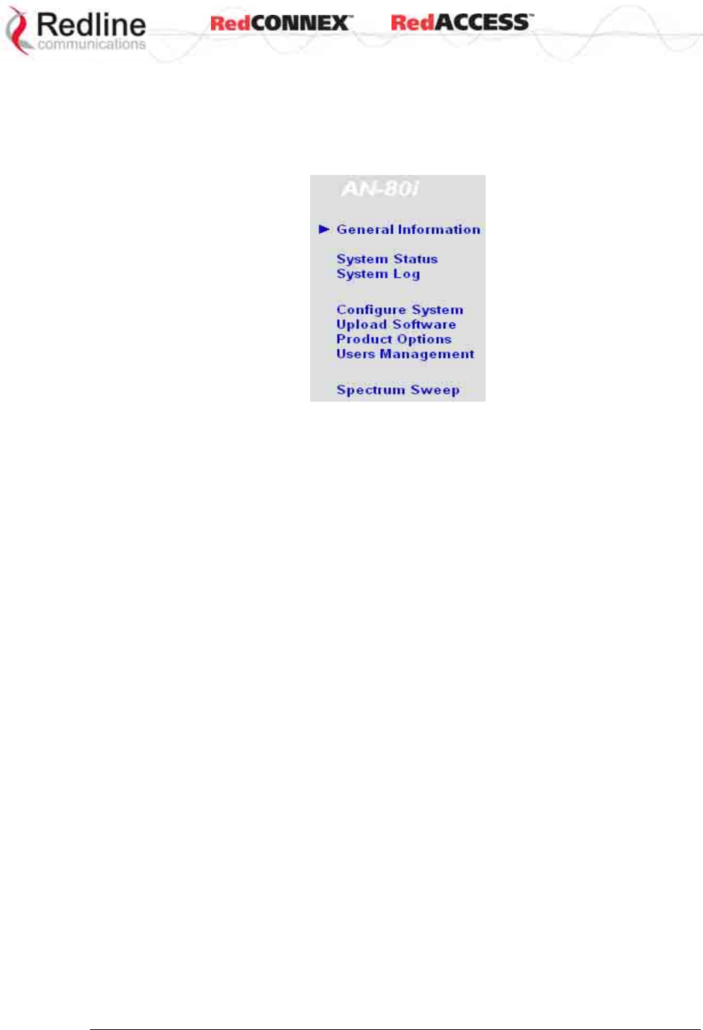
3.2 System Menu .......................................................................................... 19
3.3 System Information ................................................................................. 20
3.3.1 General Information............................................................................. 20
Dashboard........................................................................................... 20
3.3.2 General Information............................................................................. 23
General................................................................................................ 23
Ethernet............................................................................................... 24
Wireless............................................................................................... 24
3.4 System Status ......................................................................................... 25
General information............................................................................. 25
Ethernet LAN Statistics ....................................................................... 26
Wireless Statistics ............................................................................... 26
Controls ............................................................................................... 26
3.5 System Logs Screen ............................................................................... 27
3.6 System Configuration Screen.................................................................. 30
Ethernet Configuration ........................................................................ 30
Wireless Configuration ........................................................................ 33
Controls ............................................................................................... 38
3.7 Users Management ................................................................................. 39
3.8 AN-80i Product Options Screen .............................................................. 41
3.9 Upload Software...................................................................................... 42

& User
AN-80i
Manual
70-00072-01-07 Proprietary Redline Communications © 2008 Page 4 of 106 Sept 18, 2008
3.10 SNMP Settings Screen............................................................................ 43
3.10.1 Change SNMP Community ................................................................. 44
3.10.2 Change SNMP Trap Configuration...................................................... 45
3.11 Spectrum Sweep ..................................................................................... 46
4 PMP Operation....................................................................................... 48
4.1 Introduction.............................................................................................. 48
4.2 PMP Menu............................................................................................... 48
4.3 Functional Description............................................................................. 49
4.3.1 Overview.............................................................................................. 49
4.3.2 Minimum Setup Requirements ............................................................ 50
4.3.3 Packet Classification ........................................................................... 50
4.4 PMP Screens .......................................................................................... 51
4.4.1 Configuration Screen........................................................................... 51
4.4.2 Link Screen.......................................................................................... 52
4.4.3 Group Screen ...................................................................................... 53
Group .................................................................................................. 53
Wireless Traffic Parameters ................................................................ 54
4.4.4 Connection Screen .............................................................................. 55
Connection Configuration.................................................................... 55
Wireless Traffic Parameters ................................................................ 56
4.5 Browse Screens ...................................................................................... 57
4.5.1 Links Screen........................................................................................ 57
4.5.2 Groups Screen .................................................................................... 58
4.5.3 Connections Screen ............................................................................ 59
4.6 Statistics Screens.................................................................................... 60
4.6.1 Link Statistics....................................................................................... 60
4.6.2 Group Statistics.................................................................................. 61
4.6.3 Connection Statistics ........................................................................... 62
4.6.4 System Status - PMP Wireless Statistics ............................................ 63
4.7 Quick Configuration Guide ...................................................................... 63
4.7.1 Configure Pass-Through Operation..................................................... 64
Step 1: Create New Link for Each Subscriber..................................... 64
Step 2: Create Single Pass-through Group......................................... 64
Step 3: Create Connections ................................................................ 64
Step 4: Save Configuration ................................................................. 65
4.7.2 VLAN Configuration............................................................................. 65
Step 1: Change Group to VLAN Tagged............................................. 65
Step 2: Change Connections to VLAN Tagged................................... 65
Step 3: Save Configuration ................................................................. 65
5 CLI Interface........................................................................................... 66
5.1 CLI Command Summary......................................................................... 66
5.2 Connecting with Telnet............................................................................ 67
5.3 CLI Command Set................................................................................... 67
5.3.1 Chgver ................................................................................................. 67
5.3.2 Clear .................................................................................................... 68
5.3.3 Del ....................................................................................................... 68
5.3.4 Enable ................................................................................................. 68

& User
AN-80i
Manual
70-00072-01-07 Proprietary Redline Communications © 2008 Page 5 of 106 Sept 18, 2008
5.3.5 Freq ..................................................................................................... 69
5.3.6 Generate.............................................................................................. 69
5.3.7 Get....................................................................................................... 69
5.3.8 Load..................................................................................................... 71
5.3.9 Logout.................................................................................................. 72
5.3.10 New ..................................................................................................... 72
5.3.11 Ping ..................................................................................................... 72
5.3.12 Reboot ................................................................................................. 72
5.3.13 Reset ................................................................................................... 72
5.3.14 Save .................................................................................................... 73
5.3.15 Script ................................................................................................... 73
5.3.16 Set ....................................................................................................... 73
5.3.17 Show.................................................................................................... 79
5.3.18 Snmpcommunity.................................................................................. 82
5.3.19 Snmptrap ............................................................................................. 82
5.3.20 Test...................................................................................................... 82
5.3.21 Upgrade............................................................................................... 83
5.3.22 User ..................................................................................................... 83
5.3.23 Whoami ............................................................................................... 83
6 Diagnostics and Troubleshooting ....................................................... 84
6.1 Factory Default Settings .......................................................................... 84
6.2 Procedure to Restore Factory Settings ................................................... 85
6.3 Testing and Saving System Parameters ................................................. 86
6.3.1 CLI Interface ........................................................................................ 86
6.3.2 Web Interface ...................................................................................... 86
6.4 Status Codes........................................................................................... 88
6.4.1 PTP Status Codes ............................................................................... 88
6.4.2 PMP Status Codes .............................................................................. 89
7 Appendices............................................................................................ 90
7.1 AN-80i Technical Specifications.............................................................. 90
7.2 AN-80i PoE Power Adapter Specifications.............................................. 92
7.3 Antenna / Mounting Bracket Matrix ......................................................... 92
7.4 Legacy Products (Not Available to Order)............................................... 93
7.5 ETSI Certified Antennas.......................................................................... 94
7.5.1 3.3 - 3.8 GHz Radio: ETSI Certified Antennas .................................... 94
7.5.2 5.8 GHz Radio: ETSI Certified Antennas ............................................ 94
7.5.3 5.4 GHz Radio: ETSI Certified Antennas ............................................ 95
7.5.4 5.15 - 5.35 GHz Radio: ETSI Antennas............................................... 95
7.6 FCC & IC Certified Antennas .................................................................. 96
7.6.1 5.8 GHz Radio: FCC & IC Certified Antennas ..................................... 96
7.6.2 5.4 GHz Radio: FCC & IC Certified Antennas ..................................... 97
7.6.3 5.25 - 5.35 GHz Radio: FCC & IC Antennas ....................................... 97
7.6.4 4.94 - 4.99 GHz Radio: FCC & IC Antennas ....................................... 97
7.6.5 3.650 - 3.675 GHz Radio: FCC & IC Antennas ................................... 98
7.7 Regional Codes....................................................................................... 99
7.8 Security Keys and Certificates............................................................... 101
7.9 Security Certificate and Key CLI Commands ........................................ 102

& User
AN-80i
Manual
70-00072-01-07 Proprietary Redline Communications © 2008 Page 6 of 106 Sept 18, 2008
7.10 Glossary Of Terms ................................................................................ 104
LIST OF TABLES
Table 1: FCC & IC RF Recommended Safe Separation Distances .................... 11
Table 2: Wireless Link LED Diagnostics ............................................................. 20
Table 3: Wireless Signal LED Indication ............................................................. 21
Table 4: Wireless Signal LED Diagnostics.......................................................... 21
Table 5: Ethernet Link/Act LED Diagnostics ....................................................... 21
Table 6: Ethernet 100 LED Diagnostics .............................................................. 21
Table 7: Ethernet Link/Collision LED Diagnostics............................................... 22
Table 8: Web - System Log Messages ............................................................... 27
Table 9: Web - 802.1p Priority Settings .............................................................. 31
Table 10: Maximum TX Power Settings (dBm) for AN-80i Radio........................ 35
Table 11: Web - Ethernet Status Indication ........................................................ 37
Table 12: Web - Screens and User Access ........................................................ 40
Table 13: Web - Default System Users............................................................... 40
Table 14: Web - Performing a Spectrum Sweep................................................. 47
Table 15: PMP - Basic Pass-Through Group Settings........................................ 50
Table 16: PMP - Packet Classification ................................................................ 50
Table 17: PMP Maximum Achievable UBR......................................................... 52
Table 18: PMP - Basic Pass-Through Group Configuration Settings.................. 65
Table 19: CLI - Command Summary .................................................................. 66
Table 20: CLI - Root Mode Commands .............................................................. 67
Table 21: CLI - chgver......................................................................................... 67
Table 22: CLI - clear............................................................................................ 68
Table 23: CLI - del............................................................................................... 68
Table 24: CLI - enable......................................................................................... 68
Table 25: CLI - freq ............................................................................................. 69
Table 26: CLI - generate ..................................................................................... 69
Table 27: CLI - get .............................................................................................. 69
Table 28: CLI - load............................................................................................. 71
Table 29: CLI - logout.......................................................................................... 72
Table 30: CLI - new............................................................................................. 72
Table 31: CLI - ping............................................................................................. 72
Table 32: CLI - reboot ......................................................................................... 72
Table 33: CLI - reset ........................................................................................... 72
Table 34: CLI - save............................................................................................ 73
Table 35: CLI - script........................................................................................... 73
Table 36: CLI - set............................................................................................... 73
Table 37: CLI - show ........................................................................................... 79
Table 38: CLI - snmpcommunity ......................................................................... 82
Table 39: CLI - snmptrap .................................................................................... 82
Table 40: CLI - test.............................................................................................. 82
Table 41: CLI - upgrade ...................................................................................... 83
Table 42: CLI - user ............................................................................................ 83
Table 43: CLI - whoami ....................................................................................... 83
Table 44: Diag. - Factory Default Settings .......................................................... 84

& User
AN-80i
Manual
70-00072-01-07 Proprietary Redline Communications © 2008 Page 7 of 106 Sept 18, 2008
Table 45: Diag. - Web Interface Diagnostics....................................................... 87
Table 46: Diag. - PTP Status Codes ................................................................... 88
Table 47: Diag. - PMP Status Code Bits ............................................................. 89
Table 48: Diag. - PMP Status Codes .................................................................. 89
Table 49: Spec. - AN-80i Technical Specifications ............................................. 90
Table 50: Spec. - AN-80i PoE Power Adaptor Specifications ............................. 92
Table 51: Spec. - AN-80i Antenna / Mounting Bracket Matrix............................. 92
Table 52: Spec. - AN-80i Legacy Antenna / Mounting Bracket Matrix ................ 93
Table 53: Spec. - Antenna/Tx Power Setting Combinations for ETSI................. 94
Table 54: Spec. - ETSI Certified Antennas: 5.8 GHz Operation ......................... 94
Table 55: Spec. - ETSI Certified Antennas: 5.4 GHz Operation ......................... 95
Table 56: Spec. - ETSI Certified Antennas: 5.15 - 5.35 GHz Operation ............. 95
Table 57: Spec. - FCC & IC Certified Antennas: 5.8 GHz PTP Operation .......... 96
Table 58: Spec. - FCC & IC Certified Antennas: 5.8 GHz PMP Operation ......... 96
Table 59: Spec. - FCC & IC Certified Antennas: 5.4 GHz Operation.................. 97
Table 60: Spec. - FCC & IC Antennas: 5.25 - 5.35 GHz Operation .................... 97
Table 61: Spec. - FCC & IC Antennas: 4.94 - 4.99 GHz Operation .................... 98
Table 62: Spec. - Antenna/Tx Power Setting Combinations for FCC.................. 98
Table 63: Spec. - Regional Identification Codes ................................................. 99
Table 64: Security -- Keys and Certificates....................................................... 101
Table 65: Security -- Runtime Keys and Certificates ........................................ 102
Table 66: Security -- User Key and Certificate Files ......................................... 102
Table 67: Spec. - Glossary................................................................................ 104

& User
AN-80i
Manual
70-00072-01-07 Proprietary Redline Communications © 2008 Page 8 of 106 Sept 18, 2008
LIST OF FIGURES
Figure 1: Intro - AN-80i Components .................................................................. 14
Figure 2: Intro - AN-80i with Integrated Antenna................................................. 15
Figure 3: Intro - Indoor Power-over-Ethernet (PoE) Module - AC Model ............ 16
Figure 4: Intro - Indoor Power-over-Ethernet (PoE) Module - DC Model ............ 16
Figure 5: Web - Login Screen ............................................................................. 18
Figure 6: Web - System Menu ............................................................................ 19
Figure 7: Web - General Information Dashboard ................................................ 20
Figure 8: Web - General Information Screen ...................................................... 23
Figure 9: Web - System Status Screen............................................................... 25
Figure 10: Web - System Log Messages ............................................................ 27
Figure 11: Web - System and Network Configuration Screen............................. 30
Figure 12: Web - Wireless Configuration Screen................................................ 33
Figure 13: Web - Wireless Configuration Screen................................................ 34
Figure 14: Web - System Password Screen ....................................................... 39
Figure 15: Web - Product Options Screen .......................................................... 41
Figure 16: Web - Upload Software Screen ......................................................... 42
Figure 17: Web - SNMP Configuration Screen ................................................... 43
Figure 18: Web - SNMP Community Configuration Screen ................................ 44
Figure 19: Web - SNMP Trap Configuration Screen........................................... 45
Figure 20: Web - Spectrum Sweep Screen......................................................... 46
Figure 21: Web - Spectrum Sweep Results ........................................................ 47
Figure 22: PMP - Main Menu .............................................................................. 48
Figure 23: PMP - Basic Pass-through Group Configuration................................ 49
Figure 24: PMP - VLAN Tagged Traffic Example ............................................... 49
Figure 25: PMP - Wireless Settings .................................................................... 51
Figure 26: PMP - Link Configuration Screen....................................................... 52
Figure 27: PMP - Group Configuration Screen ................................................... 53
Figure 28: PMP - Connection Configuration Screen ........................................... 55
Figure 29: PMP - Links Browse Screen .............................................................. 57
Figure 30: PMP - Groups Browse Screen........................................................... 58
Figure 31: PMP - Connections Browse Screen................................................... 59
Figure 32: PMP - Link Statistics Screen.............................................................. 60
Figure 33: PMP - Group Statistics Screen .......................................................... 61
Figure 34: PMP - Connection Statistics Screen .................................................. 62
Figure 35: PMP - System Status Screen ............................................................ 63
Figure 36: PMP - Pass-through Only Deployment .............................................. 64
Figure 37: CLI - Connecting via Telnet ............................................................... 67
Figure 38: CLI - Recovering Lost IP Address...................................................... 85
Figure 39: Diag: - Saving Parameters in NVRAM ............................................... 86

& User
AN-80i
Manual
70-00072-01-07 Proprietary Redline Communications © 2008 Page 9 of 106 Sept 18, 2008
Chapter
1
1
1
I
Im
mp
po
or
rt
ta
an
nt
t
S
Sa
af
fe
et
ty
y
&
&
S
Se
er
rv
vi
ic
ce
e
N
No
ot
ti
ic
ce
es
s
1.1 Safety Warnings
PoE power adapter caution:
Warning to Service Personnel: 48 VDC
Customer equipment including personal computers, routers, etc., must be connected
only to the INPUT (DATA) port on the PoE unit.
Only the outdoors Ethernet interface cable connecting to the AN-80i can be safely
connected to the OUTPUT (DATA & POWER) connector. Connecting customer
premises Ethernet equipment directly to the OUTPUT (DATA & POWER) connector
on the Power-over-Ethernet power adapter may damage customer equipment.
1. Installation of the system must be contracted to a professional installer.
2. Read this user manual and follow all operating and safety instructions.
3. Keep all product information for future reference.
4. The power requirements are indicated on the product-marking label. Do not exceed
the described limits.
5. Use only a damp cloth for cleaning. Do not use liquid or aerosol cleaners. Disconnect
the power before cleaning.
6. Disconnect power when unit is stored for long periods.
7. The AN-80i must not be located near power lines or other electrical power circuits.
8. The system must be properly grounded to protect against power surges and
accumulated static electricity. It is the user’s responsibility to install this device in
accordance with the local electrical codes: correct installation procedures for
grounding the AN-80i, mast, lead-in wire and discharge unit, location of discharge
unit, size of grounding conductors and connection requirements for grounding
electrodes.
& User
AN-80i
Manual
70-00072-01-07 Proprietary Redline Communications © 2008 Page 10 of 106 Sept 18, 2008
1.2 Important Warning Symbols
The following symbols may be encountered during installation or troubleshooting. These
warning symbols mean danger. Bodily injury may result if you are not aware of the safety
hazards involved in working with electrical equipment and radio transmitters. Familiarize
yourself with standard safety practices before continuing.
Electro-Magnetic Radiation High Voltage
1.3 Important Service Information
1. Refer all repairs to qualified service personnel. Do not remove the covers or modify
any part of this device, as this action will void the warranty.
2. Locate the serial numbers and record these on your registration card for future
reference. Use the space below to affix serial number stickers. Also, record the MAC
address located on the AN-80i.
3. Redline does not endorse or support the use of outdoor cable assemblies: i) not
supplied by Redline, ii) third-party products that do not meet Redline's cable and
connector assembly specifications, or iii) cables not installed and weatherproofed as
specified in the Installation Guidelines manual (70-00073-01-XX). Refer to the
Redline Limited Standard Warranty and RedCare service agreements.
1.4 Lightning Protection
WARNING: The following notes are general recommendations for the system. The
wireless equipment should be installed by a qualified professional installer who must
follow local and national codes for electrical grounding and safety. Failure to meet safety
requirements and/or use of non-standard practices and procedures could result in
personal injury and damage to equipment. A direct lightning strike may cause serious
damage even if these guidelines are followed.
All outdoor wireless equipment is susceptible to lightning damage from a direct hit or
induced current from a near strike. Lightning protection and grounding practices in local
and national electrical codes serve to minimize equipment damage, service outages,
and serious injury. Reasons for lightning damage are summarized as:
a) Poorly grounded antenna sites that can conduct high lightning strike energy into
equipment.
b) Lack of properly installed lightning protection equipment that can cause equipment
failures from lightning induced currents.
A lighting protection system provides a means by which the energy may enter earth
without passing through and damaging parts of a structure. A lightning protection system
does not prevent lightning from striking; it provides a means for controlling it and
preventing damage by providing a low resistance path for the discharge of energy to
travel safely to ground. Improperly grounded connections are also a source of noise that
can cause sensitive equipment to malfunction.
A good grounding system disperses most of the surge energy from a lightning strike
away from the building and equipment. The remaining energy on the Ethernet cable
shield and center conductor can be directed safely to ground by using a lightning
arrestor in series with the cable.
& User
AN-80i
Manual
70-00072-01-07 Proprietary Redline Communications © 2008 Page 11 of 106 Sept 18, 2008
If you have determined that it is appropriate to install lightning protection for your system,
the following general industry practices are provided as a guideline only:
1. The AC wall outlet ground for the indoor POE adapter should be connected to the
building grounding system.
2. Install a lightning arrestor in series with the Ethernet cable at the point of entry to the
building. The grounding wire should be connected to the same termination point
used for the tower or mast.
3. Install a lightning arrestor in series with the Ethernet cable as close to the AN-80i as
practical. The grounding wire should be connected to the same termination point
used for the tower or mast.
4. Provide direct grounding from the AN-80i, the mounting bracket, the antenna, and
the Ethernet cable surge protection to the same ground bus on the building. Use the
grounding screws provided for terminating the ground wires.
1.5 Deployment in the USA -- FCC Notices
1.5.1 FCC & IC Notice
1. The Model AN-80i and its antenna must be professionally installed.
2. WARNING -- FCC & IC RF Exposure Warnings
To satisfy FCC and IC RF exposure requirements for RF transmitting devices, the
following distances should be maintained between the antenna of this device and
persons during device operation:
Table 1: FCC & IC RF Recommended Safe Separation Distances
Frequency (GHz) Mode Separation Distance
3.650 - 3.675 PTP / PMP 130 cm (52 in) or more
3.3 - 3.8 PTP / PMP 130 cm (52 in) or more
4.9 - 5.3 PTP / PMP 255 cm (101 in) or more
5.4 PTP / PMP 40 cm (16 in) or more
5.8 PMP 20 cm (8 in) or more
PTP 310 cm (122 in) or more
To ensure compliance, operation at closer than these distances is not
recommended. The antenna used for this transmitter must not be collocated in
conjunction with any other antenna or transmitter.
3. High power radars are allocated as primary users (meaning they have priority) of
5250-5350 MHz and 5650-5850 MHz and these radars could cause interference
and/or damage to LE-LAN devices.
4. FCC Information to Users @ FCC 15.21 & 15.105:
This equipment has been tested and found to comply with the limits for a Class A
digital device, pursuant to Part 15 of the FCC Rules. These limits are designed to
provide reasonable protection against harmful interference when the equipment is
operated in a commercial environment. This equipment generates, uses, and can
radiate radio frequency energy and, if not installed and used in accordance with the
instruction manual, may cause harmful interference to radio communications.
5. Warning: Changes or modifications not expressly approved by Redline
Communications could void the user’s authority to operate the equipment.
6. Refer to section 7.6: FCC & IC Certified Antennas for additional information.

& User
AN-80i
Manual
70-00072-01-07 Proprietary Redline Communications © 2008 Page 12 of 106 Sept 18, 2008
7. Where DFS is required by regional regulations, this function is permanently enabled
at the factory and can not be disabled by the installer or end-user. Refer to section
7.7: Regional Codes for additional information.
1.5.2 Installation and Operation
FCC Part 90 guidelines for deployment of AN-80i systems in the frequency band of
3650-3700 MHz for “restricted” CBP (Contention Based Protocol) in USA includes
restrictions on the maximum EIRP.
To comply with these guidelines, the following EIRP limitations are applied for
deployment in this band:
i) Max EIRP of 25 Watts/25 MHz (equivalent to 1 Watt/1 MHz)
ii) Peak EIRP Power Density of 1 Watt in any 1 MHz slice of spectrum.
To ensure compliance with these restrictions, refer to the following important notices:
1. The 3650-3700 MHz frequency range is a licensed band in the USA and operators
must have a valid spectrum license to operate AN-80i equipment using this band.
2. The AN-80i requires a Redline FCC-specific options key that is mandatory for
operation within the USA. This options key enforces the FCC approved operating
range of 3650-3700 MHz.
3. The AN-80i outdoor transceiver and antenna must be professionally installed.
4. Changes or modifications not expressly approved by Redline Communications could
void the user’s authority to operate the equipment.
5. Do not operate an AN-80i outdoor transceiver until you have confirmed the FCC-
specific options key is loaded and active (operating range restricted to 3650-3700
MHz). When the FCC-specific options key is installed, the operator is not able to set
an RF frequency that exceeds the allowed range of 3650-3700 MHz.
6. The AN-80i transmit power settings must not exceed values stated in the AN-80i
User Manual.
1.5.3 FCC Power Settings
FCC regulation part 90.1321 (governing operation in the 3650-3700 MHz band in the
US) states that base station transmissions are limited to a maximum transmit power of 1
Watt/MHz (peak EIRP). Refer to the section on FCC antennas at the end of this manual..
1.6 UL Information
1. The suitability of the supplied Ethernet cable is subject to the approval of Authority
Having Jurisdiction and must comply with the local electrical code.
2. The equipment must be properly grounded according with NEC and other local
safety code and building code requirements
3. To meet the over-voltage safety requirements on the telecommunications cables, a
minimum 26 AWG telecommunication line cord must be used.
4. "Pour être en conformance avec les exigences finies de sûreté de sur-tension sur les
câbles de télécommunications un fil de télécommunication ayant un calibre minimum
de 26 AWG doit être utilisé."
5. Reminder to all the BWA system installers: Attention to Section 820-40 of the NEC
which provides guidelines for proper grounding and, in particular, specifies that the
cable ground shall be connected to the grounding system of the building, as close to
the point of cable entry as is practical.

& User
AN-80i
Manual
70-00072-01-07 Proprietary Redline Communications © 2008 Page 13 of 106 Sept 18, 2008
6. AN-80i must be installed in compliance with relevant articles in National Electrical
Code-NEC (and equivalent Canadian Code-CEC) including referenced articles 725,
800 and 810 in NEC.
7. RF coaxial cable connecting an antenna to the AN-80i must comply with the local
electrical code.
1.7 Product Information
Use the following table to record important system information:
Product Information
AN-80i SN: MAC Address
PoE SN: Model #:
Antenna Model No.: Antenna SN:
Serial Number Stickers
& User
AN-80i
Manual
70-00072-01-07 Proprietary Redline Communications © 2008 Page 14 of 106 Sept 18, 2008
Chapter
2
2
2
S
Sy
ys
st
te
em
m
O
Ov
ve
er
rv
vi
ie
ew
w
The Access Node 80i system is manufactured by Redline Communications -- a world
leader in design and production of Broadband Fixed Wireless (BFW) systems.
Figure 1: Intro - AN-80i Components
The AN-80i is a high-performance, high-speed wireless Ethernet bridge for use in a
commercial, industrial, business, or government environment. The system can operate
with a 3.3-3.8, 4.9, 5.3/5.4, or 5.8 GHz radio (factory installed) using a time division
duplexing (TDD) RF transceiver to transmit and receive on the same RF channel. The
main AN-80i features include: advanced technologies to address inter-cell interference,
enhanced security features through a proprietary over-the-air encryption scheme, and
Automatic Transmitter Power Control (ATPC) to automatically achieve and maintain
optimum performance.
The AN-80i outdoor unit is housed in a weatherproof aluminum alloy case. The outdoor
unit can be used with a selection of available external antennas. When equipped with a
narrow beam antenna, the AN-80i supports long-range operations of over 50 miles (80
km) in clear line of sight (LOS) conditions. An indoor PoE power adapter provides
operational power for the AN-80i and connection to the Ethernet network.
& User
AN-80i
Manual
70-00072-01-07 Proprietary Redline Communications © 2008 Page 15 of 106 Sept 18, 2008
Each wireless link requires two AN-80i units. One AN-80i is configured as the PTP
Master (or PMP Sector Controller) and controls the wireless link. This function is
transparent to all Ethernet operations. The sector controller AN-80i uses a scheduled
request/grant mechanism to arbitrate requests for bandwidth from the remote unit --
providing non contention-based traffic with predictable transmission characteristics. The
remote AN-80i operates as a PTP Slave (or PMP Subscriber).
Figure 2: Intro - AN-80i with Integrated Antenna
2.1 Ethernet Port
The AN-80i receives DC power and exchanges data with the indoor network through the
Ethernet port. The AN-80i Ethernet port connects to the PoE Adapter using a
weatherproof Cat. 5e Ethernet cable. The Ethernet port is a female RJ-45 connector.
2.2 RF Port
The RF port is used to send and receive RF signal to/from the antenna. A short coaxial
cable is provided to connect the transceiver to an external antenna. The RF port is a
female N-type connector.
2.3 Mounting Brackets
There are two mounting brackets available for the AN-80i. The lightweight (two-point)
antenna bracket provides convenient mounting of one foot flat panel antennas. The
heavy-duty (four-point) antenna mounting bracket is available for mounting two foot flat
panel and parabolic antennas.
2.4 Grounding Connection
A ground-lug is provided on the AN-80i chassis. Use this connection to terminate a
grounding wire.
& User
AN-80i
Manual
70-00072-01-07 Proprietary Redline Communications © 2008 Page 16 of 106 Sept 18, 2008
2.5 Indoor Power Block (PoE Power Adapter)
The PoE power adapter provides power and connection to a local Ethernet network.
2.5.1 AC Power Adapter
The AC power adapter input is auto-sensing 110/220/240 VAC 50/60 Hz.
Figure 3: Intro - Indoor Power-over-Ethernet (PoE) Module - AC Model
2.5.2 DC Power Adapter
The DC power adapter input is auto-sensing 18 - 60 VDC.
Figure 4: Intro - Indoor Power-over-Ethernet (PoE) Module - DC Model

& User
AN-80i
Manual
70-00072-01-07 Proprietary Redline Communications © 2008 Page 17 of 106 Sept 18, 2008
Warning to Service Personnel: 48 VDC
Customer equipment including personal computers, routers, etc., must be connected
only to the INPUT (DATA) port on the PoE unit.
Only the outdoors Ethernet interface cable connecting to the AN-80i can be safely
connected to the OUTPUT (DATA & POWER) connector. Connecting customer
premises Ethernet equipment directly to the OUTPUT (DATA & POWER) connector
on the Power-over-Ethernet power adapter may damage customer equipment.
2.6 Antenna Alignment
The AN-80i includes both an audible alignment tool and a web-based alignment tool to
assist in pointing the antenna.
2.6.1 Web Page Alignment
The most reliable method for obtaining optimum performance from a wireless link is to
align the antenna to the position providing the highest RSSI value and the best SINADR
ratio. The web page alignment tool provides continuous updates (1 second intervals) of
the measured RSSI (received signal strength indication) and SINADR (Signal to noise
and distortion ratio). This web page can be accessed from a laptop computer and most
web-enabled handheld devices.
Use the following URL to access the AN-80i alignment web page:
http:// [AN-80i IP Address] / usr / aa.html
For example:
http://192.168.20.30/usr/aa.html
2.6.2 Audible Alignment
The signal will sound infrequently when a low signal is detected, and more often as the
signal strength increases. The audible signal is enabled and disabled through the user
interface:
Web: See Antenna Alignment Buzzer Enable under Wireless Configuration on page 33.
Telnet: See buzzer in CLI Set commands under Set on page 73.
The audible antenna alignment tool provides only rough adjustment for the subscriber
antennas. It is recommended to monitor the RSSI measurements to achieve maximum
signal strength when performing fine adjustments to the subscriber antenna. Refer to the
AN-80i Installation Guidelines for detailed instructions.
& User
AN-80i
Manual
70-00072-01-07 Proprietary Redline Communications © 2008 Page 18 of 106 Sept 18, 2008
Chapter
3
3
3
W
We
eb
b
I
In
nt
te
er
rf
fa
ac
ce
e
-
-
P
PT
TP
P
The Web Interface provides all required settings and statistics necessary to configure
and monitor the operation of the AN-80i using a standard web browser. An operator can
access and control the AN-80i remotely from any geographical location with HTTP
connectivity to that unit.
3.1 System Login
On the PC, open a browser (Internet Explorer 6 or higher recommended). For new
systems, enter the default IP address (192.168.25.2). The following dialog should be
displayed:
Figure 5: Web - Login Screen
Login to the AN-80i using your user name and password. See Table 13: Web - Default
System Users on page 40 for the factory default usernames and passwords.
If the IP address, username and/or password have been modified since installation,
contact the network administrator to determine the current settings. If the IP address, or
the user name and password cannot be determined. See section 6.2: Procedure to
Restore Factory Settings on page 85.
& User
AN-80i
Manual
70-00072-01-07 Proprietary Redline Communications © 2008 Page 19 of 106 Sept 18, 2008
3.2 System Menu
Following a successful login, the General Information screen is displayed. On the left is a
menu of all available screens. Point and click on the blue text of the menu to display that
screen.
Figure 6: Web - System Menu
The administrator (admin) has unrestricted access to all screens. All other users have
viewing access only. See 3.7: Users Management on page 39 for details.
& User
AN-80i
Manual
70-00072-01-07 Proprietary Redline Communications © 2008 Page 20 of 106 Sept 18, 2008
3.3 System Information
3.3.1 General Information
Click General Information to view the system overview screen (read-only). Refer to the
System Configuration screen for information about changing these settings.
Dashboard
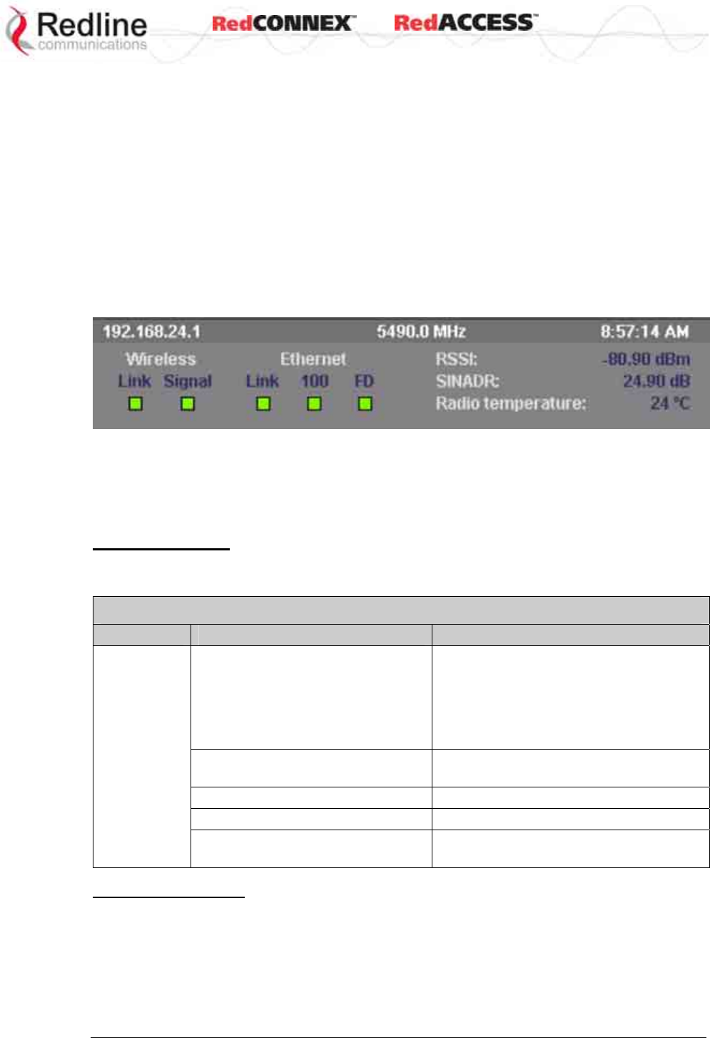
The dashboard display at the top of the General Information screen shows summary of
important operational information including: the unit IP address, operating frequency,
current time (web user's platform), wireless status, Ethernet status, Received Signal
Strength Indication (RSSI), Signal to Interference, Noise, and Distortion Ratio (SINADR),
and the radio temperature.
Figure 7: Web - General Information Dashboard
IP Address (top left of screen): Current IP address setting of this unit.
Wireless Frequency (top center of screen): User-assigned RF channel frequency.
Time (top right of screen): Displays time obtained from user's Web browser.
Wireless Link LED
The Wireless Link LED lights solid green when the wireless link is established. If the
LED is off, it may indicate one of the problems listed in the following table:
Table 2: Wireless Link LED Diagnostics
Symptom Possible Problem Solution
Link name does not match. A PTP
wireless link can be established
only between pairs of AN-80i
systems having identical Link
Name settings.
Enter identical Link Name field settings
on master and slave units. To establish a
PTP wireless link between an AN-50e
and AN-80i system, the AN-80i Link
Name field must be blank (delete all
characters).
Remote system is malfunctioning
or is not powered-on.
Verify operation of remote system.
The propagation path is blocked. Clear path or re-locate unit.
The transceiver is malfunctioning. Repair/replace unit.
No wireless
link
Antenna is not aligned with the
remote system.
Re-align the antenna.
Wireless Signal LED
The wireless signal LED lights when a wireless link is established. Signal indications are
different based on the Adaptive Modulation setting:
& User
AN-80i
Manual
70-00072-01-07 Proprietary Redline Communications © 2008 Page 21 of 106 Sept 18, 2008
Table 3: Wireless Signal LED Indication
Adaptive Modulation
Enabled The Wireless Signal LED lights solid green when the wireless link is
operating at the rate equal to the Uncoded Burst Rate setting, and
blinks when operating at a lower rate.
Disabled The Wireless Signal LED lights solid green when the wireless link is
established.
If the LED is off, it may indicate one of the problems listed in the following table:
Table 4: Wireless Signal LED Diagnostics
Symptom Possible Problem Solution
Obstructions in the propagation path
causing signal degradation.
Try to remove obstacles or re-locate
antenna.
Weak RF
Link Antenna moved, due to high winds. Re-align the antenna.
Ethernet Link LED
The Link LED lights solid green when there is an Ethernet connection and no traffic, and
blinks when traffic is detected. If the LED is off, it may indicate one of the problems listed
in the following table:
Table 5: Ethernet Link/Act LED Diagnostics
Symptom Possible Problem Solution
Poor cable connection to Ethernet
equipment.
Carefully check all cable connections.
Wrong type of cable to Ethernet
equipment.
If the Ethernet is connected to a
router, a straight-through cable is
required. If the Ethernet is connected
to a switch, a crossover cable is
required.
System processor malfunction. Apply short reset or long reset.
No Ethernet
Link
The connected Ethernet equipment
may be malfunctioning.
Repair or replace faulty equipment.
Ethernet 100 LED
The Ethernet 100 LED lights solid green when the Ethernet port is operating at 100 Mb/s
and is off when operating at 10 Mb/s. If the LED is off, it may indicate one of the
problems listed in the following table:
Table 6: Ethernet 100 LED Diagnostics
Symptom Possible Problem Solution
AN-80i is manually set for
10Base-T operation and
connected device is operating at
100Base-T or auto-negotiate.
It is strongly recommended to manually
configure all devices to matching speed
and duplex settings. If manual settings are
not available, both devices must be set to
auto-negotiate.
Ethernet 10
Mbps
The connected Ethernet device is
operating at 10Base-T.
If the AN-80i is connected to a host
computer or server operating at 10Base-T,
this is normal operation.

& User
AN-80i
Manual
70-00072-01-07 Proprietary Redline Communications © 2008 Page 22 of 106 Sept 18, 2008
Ethernet FD LED
The FD LED lights solid green when the Ethernet connection is operating in full duplex
mode and blinks when collisions are detected on the Ethernet port. When connected to a
hub, it is typical to have intermittent packet collisions. If the LED is blinking, it may
indicate one of the problems listed in the following table:
Table 7: Ethernet Link/Collision LED Diagnostics
Symptom Possible Problem Solution
Collisions are normal for half
duplex links.
Link
Collision
(FD LED
blinks)
Incompatible Ethernet port
speed.
It is strongly recommended to manually
configure all devices to matching speed
and duplex settings. If manual settings are
not available, both devices must be set to
auto-negotiate.
& User
AN-80i
Manual
70-00072-01-07 Proprietary Redline Communications © 2008 Page 23 of 106 Sept 18, 2008
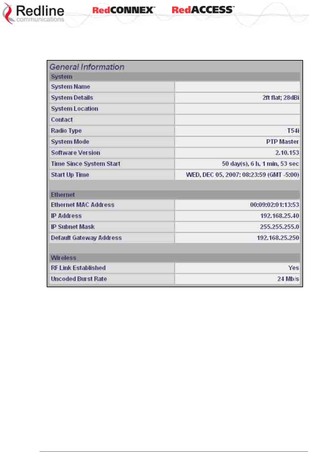
3.3.2 General Information
The General Information table provides additional detail about the unit.
Figure 8: Web - General Information Screen
General
System Name: User-assigned name for this AN-80i.
System Details: User-assigned system details information.
Contact: User-assigned contact information.
Hardware Version: Displays the hardware version of the AN-80i.
System Mode: The system designated as PTP Master establishes and manages the bi-
directional data link with a remote end AN-80i. Only one system in a wireless link must
be set for PTP Master mode.
PTP Master: AN-80i begins transmitting automatically, sends poll messages to
locate the remote AN-80i Slave, and negotiates operating settings for the link.
PTP Slave: AN-80i waits passively, monitoring the selected channel(s) until polled by
the PTP Master.
Software Version: Displays the software version in use.
Time Since System Start: Time since the system was last reset/powered-on.
Start Up Time: Time and date the system was last reset/powered-on.

& User
AN-80i
Manual
70-00072-01-07 Proprietary Redline Communications © 2008 Page 24 of 106 Sept 18, 2008
Ethernet
Ethernet MAC Address: Hardware (MAC) address of this AN-80i. This address is also
recorded on a label on the AN-80i chassis.
IP Address: User-assigned IP address of this AN-80i.
IP Subnet Mask: User assigned IP subnet mask.
Default Gateway Address: User-assigned IP address of the default router or gateway.
Wireless
RF Link Established: Status of the wireless link.
Yes - RF link successfully established with remote-end AN-80i.
No - RF link not established with remote-end AN-80i.
Uncoded Burst Rate: The current uncoded burst rate for the link.
& User
AN-80i
Manual
70-00072-01-07 Proprietary Redline Communications © 2008 Page 25 of 106 Sept 18, 2008
3.4 System Status
Click System Status in the menu to view system, Ethernet statistics, and wireless
interface statistics.
Figure 9: Web - System Status Screen
General information
System Name: Displays the user-assigned system name.
Software Version: Displays the software version in use.
RF Link Established: Status for the wireless link connection.
Yes - RF link has been successfully established with the remote-end AN-80i.
No - RF link has not been established with the remote-end AN-80i.
Uncoded Burst Rate: The negotiated uncoded burst rate (UBR) for the link.
System Mode: The PTP Master establishes and manages the wireless link with the
remote end AN-80i. Each wireless link must have only one PTP Master.
PTP Master: An-80i transmits automatically; sending poll messages to the remote
AN-80i and negotiating the UBR (modulation and coding) for the wireless link.
PTP Slave: This unit waits passively until polled by the PTP Master.
RF Channel Frequency: User-assigned RF channel.
Tx Power: The current transmit power level. If ATPC is enabled, this value may be
different than the Tx Power setting in the System Configuration screen.

& User
AN-80i
Manual
70-00072-01-07 Proprietary Redline Communications © 2008 Page 26 of 106 Sept 18, 2008
DFS Enabled: Indicate the status of the DFS feature. Refer to the Wireless
Configuration section on page 33 for a complete description of the DFS feature.
Enabled: The DFS feature is activated. See DFS Action below.
Disabled: The DFS feature is disabled.
DFS Action: Indicates the last DFS action taken by the AN-80i equipment. All DFS
actions are recorded in the event log.
None: The DFS feature is disabled.
Tx Off: Transmitter was switched off for 30 minutes.
Chg Freq: Transmitter was switched to a different frequency.
Link Distance [Miles or Km]: Distance between wireless systems. This may be the
calculated or user-assigned distance (System Configuration screen).
Status Code: Code indicating the condition of the AN-80i system. Status indications are
specific for PMP and PTP operation.
Ethernet MAC Address: System hardware address (also printed on product label).
IP Address: User-assigned IP address of the AN-80i.
IP Subnet Mask: User-assigned IP subnet mask.
Default Gateway Address: User-assigned IP for the default router or gateway.
Ethernet LAN Statistics
Rx Packets: Total packets received on the Ethernet port.
Rx Packets: Discarded: Total valid Ethernet frames received on the Ethernet port that
are discarded due to lack of buffer space.
Tx Packets: Number of packets transmitted on the Ethernet port (including Ethernet frames
and error correction bytes).
Wireless Statistics
Link ID: A unique Link ID value is generated automatically when a new link is added.
Received Signal Strength: Min: Minimum measured RSSI value.
Received Signal Strength: Mean: Average measured RSSI value.
Received Signal Strength: Max: Maximum measured RSSI value.
SINADR: Ave. signal to interference, noise, and distortion ratio measured since last refresh.
Rx Packets: Total number of packets received over the wireless interface.
Rx Packets: Retransmitted Number of wireless packets received that were retransmitted
by the remote-end system (ARQ mechanism re-transmitting unacknowledged packets).
Rx Packets - Discarded: Number of received packets discarded due to errors.
Tx Packets: Number of packets transmitted over the wireless interface.
Tx Packets - Retransmitted: Number of packets re-transmitted over the wireless interface
(ARQ mechanism re-transmitting unacknowledged packets).
Tx Packets: Discarded: Total number of packets transmitted over the wireless interface
that were not acknowledged (discarded by remote-end due to errors).
Controls
Reset Statistics: Click this button to zero the counters for the wireless and Ethernet LAN
Statistics displayed on this page.
& User
AN-80i
Manual
70-00072-01-07 Proprietary Redline Communications © 2008 Page 27 of 106 Sept 18, 2008
3.5 System Logs Screen
Click System Log in the menu to view the system activity and error messages recorded
by the AN-80i.
Figure 10: Web - System Log Messages
The following table provides a brief description of the key messages recorded in the logs
by the system.
Table 8: Web - System Log Messages
Log Message Description
1001 System Configuration Load: OK
1002 System Configuration Save: OK
1003 EEPROM Directory Load: OK
1004 EEPROM Directory Save: OK
1005 User Configuration Load: OK
1006 User Configuration Save: OK
1007 Network Configuration Load: OK
1008 Network Configuration Save: OK
1009 Network Configuration: OK
1010 Version Ctrl Data Load: OK
1011 Version Ctrl Data Save: OK
1012 System Description Load: OK
1013 System Description Save: OK
1014 Options Key Load: OK
1015 Options Key Save: OK
1016 Options Key Properties Load: OK
1017 Options Key Properties Save: OK
1018 Options Key Activated: OK
1019 Data server started: OK
1021 Upgrade: OK
1023 Firmware configuration: OK

& User
AN-80i
Manual
70-00072-01-07 Proprietary Redline Communications © 2008 Page 28 of 106 Sept 18, 2008
Table 8: Web - System Log Messages
Log Message Description
1026 Factory Data Save: OK
1029 HTTP(User Mgm): Chg User Attributes: OK
1030 SNMP Configuration Load: OK
1031 SNMP Configuration Save: OK
1032 SNTP: Time received: OK
1033 DFS: Event Detected
1033 MAC Initialization: OK
1034 DFS: Event Detected
1035 ID deleted: OK
1036 Restart freq scan (RSSI)
1037 Restart freq scan (TimeOut)
1038 Reg Req (step 1)
1039 Reg Req (step 2
1040 Reg Req (step 2)
1041 Restart freq scan (!act links)
1042 ID tables saved: OK
1043 ID defined: OK
1044 ID tables not changed: OK
1045 ID modified: OK
1046 RF frequency validation: OK
2001 System Configuration Load: Error
2002 System Configuration Save: Error
2003 EEPROM Directory Load: Error
2004 EEPROM Directory Save: Error
2005 User Configuration Load: Error
2006 User Configuration Save: Error
2007 Network Configuration Load: Error
2008 Network Configuration Save: Error
2009 Network Configuration: Error
2010 Version Ctrl Data Load: Error
2011 Version Ctrl Data Save: Error
2012 System Description Load: Error
2013 System Description Save: Error
2014 Options Key Load: Error
2015 Options Key Save: Error
2016 Options Key Properties Load: Error
2017 Options Key Properties Save: Error
2018 Options Key Activated: Error
2019 No Options Key
2020 Fail to start the data server
2021 Data server
2022 Data server

& User
AN-80i
Manual
70-00072-01-07 Proprietary Redline Communications © 2008 Page 29 of 106 Sept 18, 2008
Table 8: Web - System Log Messages
Log Message Description
2023 Upgrade client start: Error
2024 Upgrade in progress
2025 Upgrade: FAIL
2026 Upgrade: Error
2028 Factory Data Corrupted (use fallback values)
2028 TFTP: Error
2029 Firmware configuration: Error
2031 Factory Data Save: Error
2034 HTTP(User Mgm): Invalid password
2035 HTTP(User Mgm): Invalid User
2036 HTTP(User Mgm): Chg User Attributes: Error
2037 SNMP Configuration Load: Error
2038 SNMP Configuration Save: Error
2039 Invalid Options Key
2039 SNTP: Time received: Error
2040 MAC Initialization: Error
2041 MAC Busy
2042 ID database corrupted
2043 Invalid ID
2044 Max. ID number reached
2045 Int Procs programming: Error
2046 Int Procs start: Error
2047 ID action not possible
2048 ID validation: Error
2049 HW validation: Error
2050 FTP: Error
2051 RF frequency validation: Error
2099 Unknown Message
& User
AN-80i
Manual
70-00072-01-07 Proprietary Redline Communications © 2008 Page 30 of 106 Sept 18, 2008
3.6 System Configuration Screen
Click Configure System in the menu to view and adjust configuration settings for general
system identification, Ethernet, and the wireless interface.
Figure 11: Web - System and Network Configuration Screen
Ethernet Configuration
System Name: Enter the name for this AN-80i. The name may be up to thirty (30) alpha-
numeric characters including a-z, A-Z, 0-9, dash (-), and underscore (_).
System Details: Enter additional descriptive details about this AN-80i. The name may
be up to thirty (30) alpha-numeric characters including a-z, A-Z, 0-9, dash (-), and
underscore (_).
System Location: Enter additional descriptive details about this AN-80i. The name may
be up to thirty (30) alpha-numeric characters including a-z, A-Z, 0-9, dash (-), and
underscore (_).
Contact: Enter additional descriptive details about this AN-80i. The name may be up to
thirty (30) alpha-numeric characters including a-z, A-Z, 0-9, dash (-), and underscore (_).
& User
AN-80i
Manual
70-00072-01-07 Proprietary Redline Communications © 2008 Page 31 of 106 Sept 18, 2008
IP Address: Enter the IP address for this AN-80i. The IP address is routable through the
Ethernet port and over the wireless interface.
IP Subnet Mask: Enter the IP subnet mask.
Default Gateway Address: Enter the IP address of the default gateway or router on the
Ethernet segment connected to the AN-80i Ethernet port.
Flow Control Enable: Check this box to enable flow control functions (802.3x) on the
AN-80i Ethernet port. Enabling this feature allows the AN-80i to request Ethernet
devices to pause transmissions during busy periods.
Prioritized Low Latency Mode Enable: Check this box to enable priority handling of
802.1p tagged traffic. When enabled, this ensures prioritized traffic is transmitted with
the lowest achievable latency, even under conditions of high IP data traffic loading.
Table 9: Web - 802.1p Priority Settings
Priority Setting
Highest 6, 7
4, 5
0, 3, no tag
Lowest 1, 2
SNTP Enable: Check this box to enable the SNTP protocol support. This feature
allows AN-80i systems to time-stamp log messages using a network time server. When
enabled, you must enter the network address of the SNTP server in the SNTP Server IP
Address field.
SNTP Server IP Address: Enter the network address of the SNTP server. Valid only
when the SNTP Enable field is checked.
Polling Interval: Enter the SNTP polling interval (hours).
Time Zone (GMT): Enter the hours offset from GMT for this time zone. Valid only when
the SNTP Enable field is checked.
Syslog Enable: Check this box to enable the Syslog protocol support. This feature
allows AN-80i log messages to be saved in a central repository. When enabled, you
must enter the network address of the Syslog server in the Syslog Server IP Address
field.
Syslog Server IP Address: Enter the network address of the Syslog server. Valid only
when the Syslog Enable field is checked.
Ethernet Mode: Select the operating mode of the Ethernet port.
Auto - Auto-negotiate the speed connection speed.
10 - Operate at 10Base-T only.
100 - Operate at 100Base-T only.
HD - Operate at half-duplex only.
FD - Operate in full duplex only.
Important: The auto-negotiate feature does not detect the speed and duplex of
manually set Ethernet equipment. The auto-negotiate feature works correctly only
when both communicating Ethernet devices are configured for auto-negotiate. Duplex
mismatches may result in an unexpected loss of communications.
It is recommended to manually configure Ethernet devices to 100Base-T / full duplex.
& User
AN-80i
Manual
70-00072-01-07 Proprietary Redline Communications © 2008 Page 32 of 106 Sept 18, 2008
HTTP Enable: Check this box to enable the HTTP (Web) interface. If the option is
deselected, only CLI commands will be available.
Telnet Enable: Check this box to enable a Telnet access (CLI) to the AN-80i. Refer
to the CLI commands in CLI Interface on page 66.
Telnet Port: Enter Telnet port address (default is 23).
SNMP Enable: Check this box to enable the Simple Network Management Protocol
(SNMP) agent. When this item is checked, click on the blue text [Configure SNMP]
adjacent to the check box to display the SNMP Configuration screen.
Mgmt. Tag Enable: Check this box to enable VLAN tagged traffic.
The Mgmt Tag Enable setting is disabled (factory default) when shipped from the factory
or following a long-reset operation. In this mode the PTP Master and PTP Slave can be
managed through the local Ethernet port using untagged traffic. Over-the-air
management is possible only after creating a pass-through group and pass-through
connections for each PTP Slave.
When Mgmt Tag Enable is enabled, this PTP Master or PTP Slave can be managed
only using VLAN traffic tagged with the value specified in the Mgmt. VID field. Over-the-
air management is possible only after creating a VLAN tagged group and VLAN tagged
connections for each PTP Slave.
It is recommended to create and test a VLAN group for tagged management traffic
before activating the Mgmt Tag Enable function. Set the associated QoS and priority
values to ensure management traffic has adequate priority and bandwidth during system
operation.
Mgmt. VID: Enter the VLAN ID. When Mgmt. Tag Enable is selected, the system
recognizes only management commands with this VLAN ID.
Important: The VLAN network support should be verified before enabling this feature
to ensure the AN-80i system will be reachable using the VLAN tagged traffic.
& User
AN-80i
Manual
70-00072-01-07 Proprietary Redline Communications © 2008 Page 33 of 106 Sept 18, 2008
Wireless Configuration
Use settings on the following screen to configure the AN-80i wireless interface.
Figure 12: Web - Wireless Configuration Screen
RF Freq. [MHz]: Enter the center frequency for the RF channel. This setting must be
identical for both AN-80i systems operating as a wireless link. The options key controls
channel availability. Refer to Table 63: Spec. - Regional Identification Codes on page 99
for available channels. Use the Autoscan feature to enable use of multiple channels.
When the Auto Scan field is not checked, the PTP Slave will only register with a PTP
Master operating at the frequency specified in the RF Freq. [MHz] field.
Important: To minimize interference, the channel frequencies for AN-80i links
operating in close proximity should be separated by a minimum of the channel size in
use (to avoid overlapping bands).
Auto scan: Check this box to enable the PTP Slave automatically scan available
channels to locate and register with an AN-80i PTP Master. When the Auto Scan field is
checked, click on the blue text [Frequency Ranges] adjacent to the check box to display
& User
AN-80i
Manual
70-00072-01-07 Proprietary Redline Communications © 2008 Page 34 of 106 Sept 18, 2008
the Frequency Management screen. Up to 32 frequency ranges may be specified.
Frequency ranges may be entered on the PTP Master and the PTP Slave. Settings
entered on the PTP Master will be downloaded and used by the PTP Slave.
Figure 13: Web - Wireless Configuration Screen
Add Frequency Range
Begin: Enter the lower limit of the frequency scan interval (MHz). The scan interval must
be a subset of the region frequency range. The AN-80i compensates for channel size
when selecting the center frequency.
End: Enter the upper limit of the frequency scan interval (MHz). The scan interval must
be a subset of the region frequency range. The AN-80i compensates for channel size
when selecting the center frequency.
Add: Click to check the range settings and add these to the Local Frequency Range list
(if valid). To save changes to non-volatile memory, return to the Configuration Screen
and click the Save button at the bottom of the screen.
Delete Frequency Range
Index: Select the index value for the scan interval delete from the Local Ranges table.
Delete: Click the Delete button to permanently remove the selected scan interval.
Local Frequency Ranges:
These are the (optional) scan intervals for this PTP Slave. The last settings saved in
non-volatile memory will be loaded when the PTP Slave is rebooted.
Remote Frequency Ranges:
When settings are displayed in this table, the frequency scan intervals have been
downloaded from the PTP Master. Setting scan intervals in the PTP Master is optional.
When present, these settings override the local settings and are used whenever the PTP
Slave has deregistered and is scanning for a PTP Master. This list is not saved
permanently, and is discarded when the PTP Slave is rebooted.
Reload: Display the saved (Local) scan intervals.
& User
AN-80i
Manual
70-00072-01-07 Proprietary Redline Communications © 2008 Page 35 of 106 Sept 18, 2008
Save: If settings are valid, the ranges are added to the Local Frequency Range list. An
event message is logged indicating the results of the test.
Important: Clicking the Save button does not permanently save changes. You must
click Save at the bottom of the System Configuration screen.
Test: Click to check the range settings and add these to the Local Frequency Range list
(if valid). This action does not save the changes to non-volatile memory.
Operating Notes
If no scan intervals are defined, the PTP Slave will scan all frequency ranges for the
enabled region. If scan intervals are defined, only the listed channels will be scanned for
a PTP Master. If the PTP Slave checks all scan intervals three times without locating
and registering with a PTP Master, the scanning mode is changed to include all
frequency ranges for the enabled region (until registration or reboot).
The PTP Master can also be programmed with a list of scan intervals. When the PTP
Slave registers with a PTP Master that has frequency ranges defined, the list is
transmitted to the PTP Slave and is displayed as Remote Frequency Ranges. When
present, the scan intervals in the Remote Frequency Ranges table are used exclusively
during autoscan (Local Frequency Ranges are ignored). The Remote Frequency
Ranges remain in effect until the PTP Slave is rebooted.
Tx Power [dBm]: Enter the transmit power level (dBm). This setting is for the
transceiver output only. The actual EIRP depends on the gain of the connected antenna.
Refer to the following tables to determine the maximum transmit power level available at
each modulation setting. When ATPC is enabled, the Tx power is automatically adjusted
to achieve optimum performance. When DFS is enabled, the subscriber Tx power may
be automatically adjusted (regardless of ATPC setting) to avoid false DFS triggering.
Table 10: Maximum TX Power Settings (dBm) for AN-80i Radio
Modulation BPSK QPSK 16 QAM 64 QAM
Code Rate 1/2 3/4 1/2 3/4 1/2 3/4 2/3 3/4
Max. Tx Power:
T35 Radio 25 25 25 25 25 23 22 21
Max. Tx Power:
T49 / T54 / T58 Radio 25 25 23 22 21 20 18 17
PTP: v3.00 or higher / PMP: v11.0 or higher
.
Note: In PMP mode, setting the Tx power too high may reduce the SINADR value. If the
SINADR is less than expected, re-test the link using a lower Tx power setting.
Important: EIRP Levels: Where required by local regulations, the maximum
operational power per channel for a specific antenna must not exceed the maximum
allowable EIRP levels. Refer to the FCC and CE notices in this manual. The RF output
power settings must be professionally programmed by the manufacturer or a trained
professional installer. See section 7: Appendices for a list the maximum transmit power
setting based on the antenna gain for a series of frequency settings.

& User
AN-80i
Manual
70-00072-01-07 Proprietary Redline Communications © 2008 Page 36 of 106 Sept 18, 2008
DFS Action: Select the mode of operation for DFS.
The system set to PTP Master monitors for interference from radar devices and other
equipment using the same channel frequency. When interference is detected, the
system automatically takes the action selected using the drop-down menu.
None: The DFS function is disabled.
Tx Off: When radar signals are detected the transmitter is switched off for 30
minutes. This action is recorded in the message log and an SNMP trap message is
sent (if SNMP enabled).
Following an interval of thirty minutes, the same channel is monitored for one minute
and if there are no DFS triggering events, the system resumes normal operation. If
DFS trigger conditions are still detected, operation is suspended for an additional
thirty minutes. This cycle continues until no DFS trigger events are detected or the
operator manually reconfigures the system.
Chg Freq: When radar signals are detected the transmitter is switched to a different
frequency. This action is recorded in the message log and a trap message is sent (if
SNMP enabled).
The new channel is selected based on allowable frequencies for the regulatory
region of that installation. The channel is monitored for one minute before the system
is allowed to transmit. If DFS triggering events are detected, the next available
channel is selected and monitored. The system is not allowed to return to a channel
on which DFS trigger events were detected for a period of thirty minutes. If DFS
trigger events are detected on all channels, operation is suspended until the thirty-
minute time interval expires for at least one channel.
Important: Where DFS is required by regional regulations, this feature is permanently
enabled at the factory and can not be disabled by the installer or end-user.
Antenna Gain: Enter the gain (dBm) for the system antenna.
It is important that the Antenna Gain setting matches the actual antenna gain. If the
antenna gain is set higher than the true antenna gain, the system is less sensitive to
detecting interference, and is not operating in compliance with the UK/ETSI standard. If
the antenna gain is set lower than the true antenna gain, the system is more sensitive to
interference and this may result in false DFS triggers.
ATPC Enable: Check this box to enable the AN-80i to monitor the received signal
and request that the remote system adjustment its transmit level for optimum
performance. The ATPC feature must be enabled on both AN-80i units.
Important: When ATPC is enabled, best results are obtained by enabling adaptive
modulation.
Adaptive Modulation: Check this box to enable the AN-80i to automatically adjust
the transmission modulation and code settings to achieve the highest UBR that will
operate with a packet error rate (PER at layer 2) of less than 1x10e-6. If the PER
exceeds 1x10e-6, the AN-80i automatically adjusts the modulation and code settings
downwards (i.e., from 16 QAM 3/4 to 16 QAM 1/2) to operate at a lower UBR where the
PER is acceptable. When disabled, the modulation and code settings are entered
manually using the Uncoded Burst Rate setting. See Table 10: Maximum TX Power
Settings (dBm) for AN-80i Radio.
Modulation Reduction Level: Enter the number of modulation/coding levels to step
down during re-transmission of errored wireless packets. Each step down lowers the
UBR. The level can be set from 0 to 7 (recommended value = 2).
& User
AN-80i
Manual
70-00072-01-07 Proprietary Redline Communications © 2008 Page 37 of 106 Sept 18, 2008
Uncoded Burst Rate [Mb/s]: Select the desired UBR for the link. If Adaptive Modulation
is disabled, the AN-80i will transmit using only the specified settings. See Table 10:
Maximum TX Power Settings (dBm) for AN-80i Radio.
Channel Width [MHz]: Select the channel bandwidth. Refer to Table 63: Spec. -
Regional Identification Codes on page 99 for available channel widths.
Ethernet Follows Wireless: Check this box to have the AN-80i disable and enable
the Ethernet port function based on the status of the wireless interface. This feature
allows switches and routers to trigger configuration changes based on changes to the
AN-80i Ethernet port status.
Disabled ( ): The AN-80i Ethernet port is always enabled.
Enabled ( ):Ethernet port is controlled based on the status of the wireless interface.
Table 11: Web - Ethernet Status Indication
Wireless interface Status Ethernet Port Status
Link Up Enabled
Link Down Disabled
Important: The Ethernet Follows Wireless setting affects all data and management
traffic (HTTP, TELNET, and SNMP). While activated, it is not possible to manage the
AN-80i using the Ethernet port.
Ethernet follows wireless timeout [sec]: Enter the period (in seconds) the Ethernet
port will remain disabled following loss of connectivity on the wireless interface.
Following this interval, the Ethernet port will be automatically re-enabled to allow
management of the AN-80i.
Important: When Ethernet Follows Wireless Timeout is enabled, external
switches/routers monitoring the Ethernet port must be programmed to not switch
automatically when the Ethernet port function is restored -- the wireless interface may
not be operational.
System Mode: Set the operating mode for each AN-80i system.
PTP Master: This unit begins transmitting automatically; sends poll messages to the
remote AN-80i, and negotiates the wireless link.
PTP Slave: This unit waits passively, monitoring the selected channel(s) until polled
by the PTP Master, and participates in negotiating the wireless link.
Software Version: Select the version of system software to load when the AN-80i is
rebooted. The system holds two independent software images.
Encryption Type: Select an encryption type for data transmitted over the wireless
interface. When encryption is enabled, no Ethernet packets can be transferred over-the-
air unless encryption is enabled on the remote-end AN-80i and the correct Encryption
Key is entered on both AN-80i units.
None: Encryption is disabled.
Redline 64-bit: Redline proprietary encryption scheme, compatible with AN-50e.
AES 128-bit: Advanced Encryption Standard using 128-bit encryption.
AES 192-bit: Advanced Encryption Standard using 192-bit encryption.
AES 256-bit: Advanced Encryption Standard using 256-bit encryption.

& User
AN-80i
Manual
70-00072-01-07 Proprietary Redline Communications © 2008 Page 38 of 106 Sept 18, 2008
Encryption Key: The key is used to encrypt data in a way that can be decoded by the
remote-end AN-80i. Enter the MAC address of the communicating AN-80i.
Link Name: Enter the name to be used for both the local and remote-end system. A
PTP wireless link can be established only between pairs of AN-80i systems having
identical Link Name settings. This feature ensures that on power-up, reboot, or auto
scan (following deregistration or DFS event), wireless links will only register with
designated remote-end units. The name may be up to thirty (30) alpha-numeric
characters including a-z, A-Z, 0-9, dash (-), and underscore (_).
Important: To establish a PTP wireless link between an AN-50e and AN-80i system,
the AN-80i Link Name field must be blank (delete all characters).
Link Length Measurement Mode: Select the mode for setting/measuring the distance
between this and the remote-end AN-80i.
Auto: Distance is calculated automatically by the AN-80i.
Manual: Enter the link distance manually in the Link Length field.
Link Length: Enter the actual length of the path that the radio wave travels between the
two AN-80i units. The link length is used to calculate the transmission-to-response
interval and reject reflections of the transmitted signal. This setting is valid only when the
Link Length Mode is set to Manual.
Link Length Measurements Unit: Select the units for the Link Length field.
Mile: Link length distance is displayed in miles.
Km: Link length distance is displayed in kilometers.
Antenna Alignment Buzzer Enable: Check this box to enable the antenna alignment
audible tone generator in the transceiver. The rate of the tone is proportional to the
receive signal strength (faster = stronger signal).
Radio Enable: Check this box to enable the radio transmitter. If this box is unchecked
(), it will not be possible to establish a wireless link.
Controls
Save: Click to save settings currently displayed in the configuration screen. Changes to
some parameters cause a system reset when the Save button is selected.
Test: Click this button to load the current settings displayed in the configuration screen.
The AN-80i will operate with these settings for a period of five minutes. During the 'test'
period, you may click the Save button at any time to save this configuration permanently
(also terminating the five minute timer). If the Save button is not selected, the previous
saved settings are reloaded.
Reboot: Click this button to immediately reboot the AN-80i. All statistics counters are
reset.
Def Cfg: Click this button to change all configuration settings to factory default values.
Chg Ver: Click this button to toggle between software versions (on next reboot).
& User
AN-80i
Manual
70-00072-01-07 Proprietary Redline Communications © 2008 Page 39 of 106 Sept 18, 2008
3.7 Users Management
Click Users Management in the left hand menu to display the System Password screen.
This screen allows the operator to modify the system passwords.
The AN-80i supports two groups of users: admin and user. See Table 13: Web - Default
System Users on 40 for the factory default login values. See Table 12: Web - Screens
and User Access on page 40 for permissions associated with each group.
Important: There must always be at least one 'administrator' account active
on the AN-80i. You can not manage the AN-80i if all accounts are 'user'.
Figure 14: Web - System Password Screen
Change User Settings
Use this dialog to change the settings for an existing user.
User name: Select an existing user to be modified.
Group: Select the group to be associated with this username.
New Password: Enter the new password for this user.
Confirm Password: Re-enter new password for this user.
Admin Password: Enter the administrator password (security feature).
Change: Click the Change button to make these changes effective.
Add User
Use this dialog to add a new user.
& User
AN-80i
Manual
70-00072-01-07 Proprietary Redline Communications © 2008 Page 40 of 106 Sept 18, 2008
User name: Enter a name for the new user (15 characters max.).
Group: Select a group for the new user.
New Password: Enter a password for the new user (15 characters max.).
Confirm Password: Re-enter the password for the new user.
Admin Password: Enter the administrator password (security feature).
Add: Click the Add button to make these changes effective.
Delete User
Use this dialog to delete an existing user.
User name: Select an existing user.
Admin Password: Enter the administrator password (security feature).
Del: Click the Del button to make these changes effective.
Group Permissions
The following table lists the permissions associated with each group.
Table 12: Web - Screens and User Access
Screen Admin
Access User
Access Description
General Information X X View general system identification and
configuration settings.
System Status X X View system information, Ethernet statistics, and
wireless statistics.
System Log X X View the system status messages recorded by
the AN-80i.
Configure System X View and adjust configuration system, IP
address, management, and wireless settings.
Upload Software X Upload a new software binary file.
Users Management X
X
X Change your login password.
Add and delete users.
Product Options X View and change the product options key.
Spectrum Sweep X Scan a range of frequencies to detect other RF
sources (interference).
Links X Display user-defined Links.
Groups X Display user-defined Groups.
New Link X Create a new Link.
New Group X Create a new Group.
New Connection X Create a new Connection.
Save X Save changes to ID table (Links, Groups, etc).
Clear All X Clear all entries in the ID table.
The following table lists the default login names and passwords.
Table 13: Web - Default System Users
Group User Name Default Password
user user user
admin admin admin
& User
AN-80i
Manual
70-00072-01-07 Proprietary Redline Communications © 2008 Page 41 of 106 Sept 18, 2008
3.8 AN-80i Product Options Screen
Click Product Options in the left hand menu to display the Product Options screen. The
options keys (a string of numbers, letters, and dashes) enable AN-80i features including
the maximum uncoded burst rate and frequency ranges (region codes). Options key are
unique to a specific AN-80i (keyed to MAC address).
At least one valid permanent options key must be purchased and installed before the
AN-80i is placed in-service. A second options key (permanent or temporary key) may be
added to trial new options without deleting the current key.
Important: If the AN-80i is placed in-service without first entering a purchased
permanent Options Key -- you will experience a service outage on the wireless
link.
Figure 15: Web - Product Options Screen
Options Key 1: Enter a valid permanent or temporary options key.
Options Key 2: Enter a valid permanent or temporary options key.
Active Options Key: The Active Options Key field selects the preferred key. If valid, the
selected key will be activated immediately when the Activate button is clicked. This
selection is not affected by switching software versions. If the selected key expires
(temp) or the mode is changed (PTP/PMP) the AN-80i will switch to the standby key (if
valid).
Important: If the active options key is a temporary key -- always enter and
activate a purchased permanent options key before the temporary key expires --
otherwise you will experience a service outage on the wireless link.
Activate: Click the Activate button to validate, save, and activate new options keys or
changes to the Active Options Key setting. All keys are validated when the Activate
button is clicked. Invalid keys are discarded and an error message is recorded in the
event log. If two keys are entered in the same session (before clicking Activate), values
are saved only if both keys are valid.
Notes:
1. Keys are shared between PMP and PTP operation.
2. PTP mode has the following restricted operation when both options keys are invalid: 10 MHz
channel, 3 Mbps UBR, DFS permanently enabled, region based common frequency range,
no enhanced options (i.e., AES).
3. A valid options key must be entered to enable PMP mode operation.
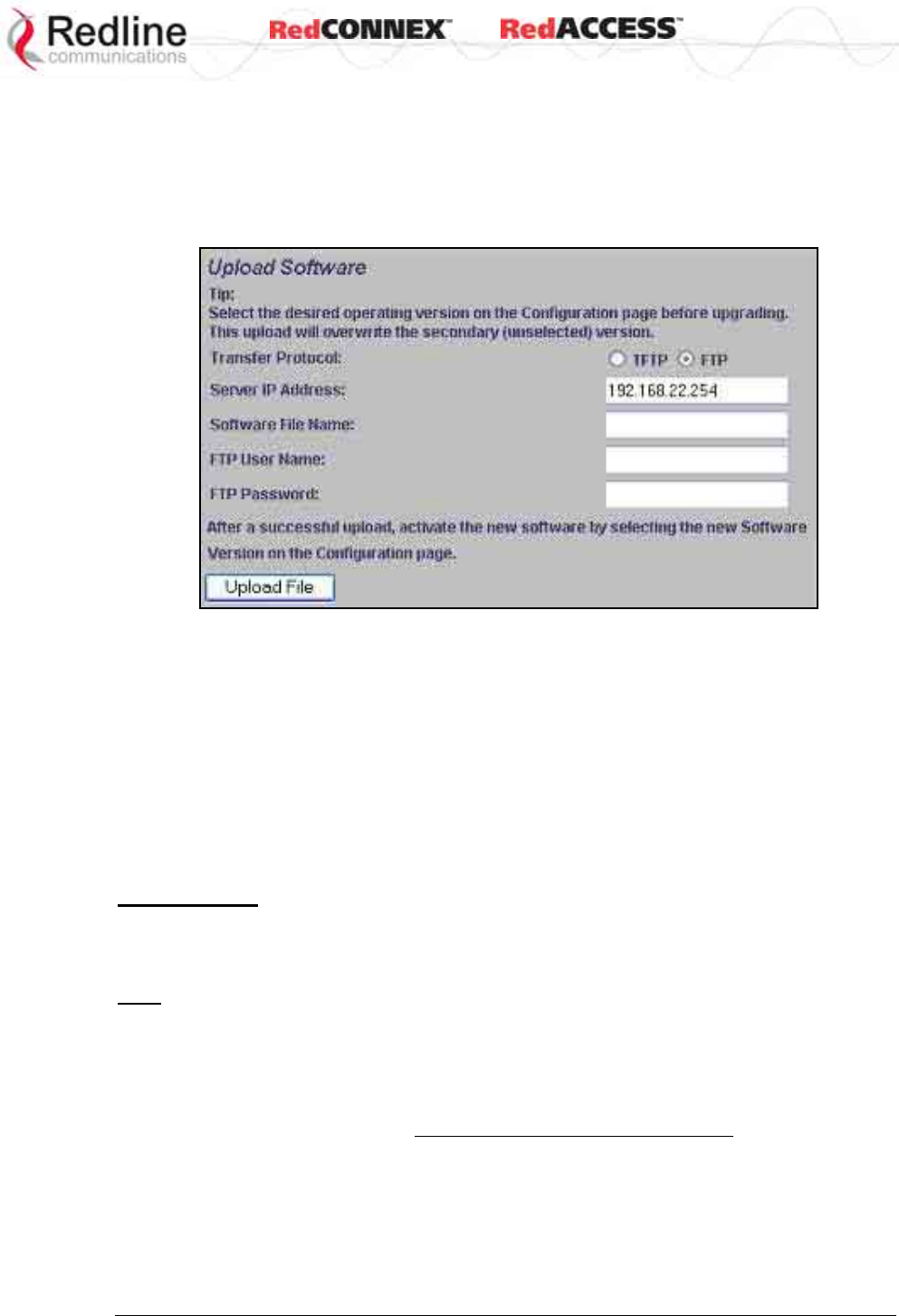
& User
AN-80i
Manual
70-00072-01-07 Proprietary Redline Communications © 2008 Page 42 of 106 Sept 18, 2008
3.9 Upload Software
Click Upload Software in the left hand menu to display the Upload Software screen. This
screen is used to upgrade the AN-80i with new software. The AN-80i contains non-
volatile storage for two versions of the software. The upload overwrites the non-
operational (unselected) version.
Figure 16: Web - Upload Software Screen
Transfer Protocol: Select the type of server:
TFTP: Use Trivial File Transfer Protocol for file upload.
FTP: Use File Transfer Protocol for file upload.
Server IP Address: Enter the IP address of the computer with the software upgrade file.
The designated computer must be running a TFTP/FTP server.
Software File Name: Name of the software binary file (including file extension).
FTP User Name: Enter the user account name on the FTP server.
FTP Password: Enter the password for the user account name on the FTP server.
Upgrade Steps
A TFTP/FTP server is used to upload the new software image file from your computer to
the AN-80i. TFTP/FTP server software must be installed and running on the computer
you are using to upload the new software file. In addition, the AN-80i software binary file
must be located in the default upload directory for the TFTP/FTP server.
1. Enter the IP Address of the computer running the TFTP/FTP server.
2. Enter the full name of the binary file (including the .bin extension).
3. Click Upload File to begin the file transfer. The upgrade file size is approximately four
Megabytes and takes a minimum of four to eight minutes to transfer. Slower network
connections may take longer. Do not interrupt the transfer process.
4. When the transfer is complete, the AN-80i verifies the integrity of the new file. If
errors were introduced during the transfer process, the software file is rejected and a
warning message is registered in the event log, and you must repeat the upload.
5. When the transfer has completed successfully, use the System Configuration screen
to select which software version to load on the next system reboot (does not switch
automatically following upload).
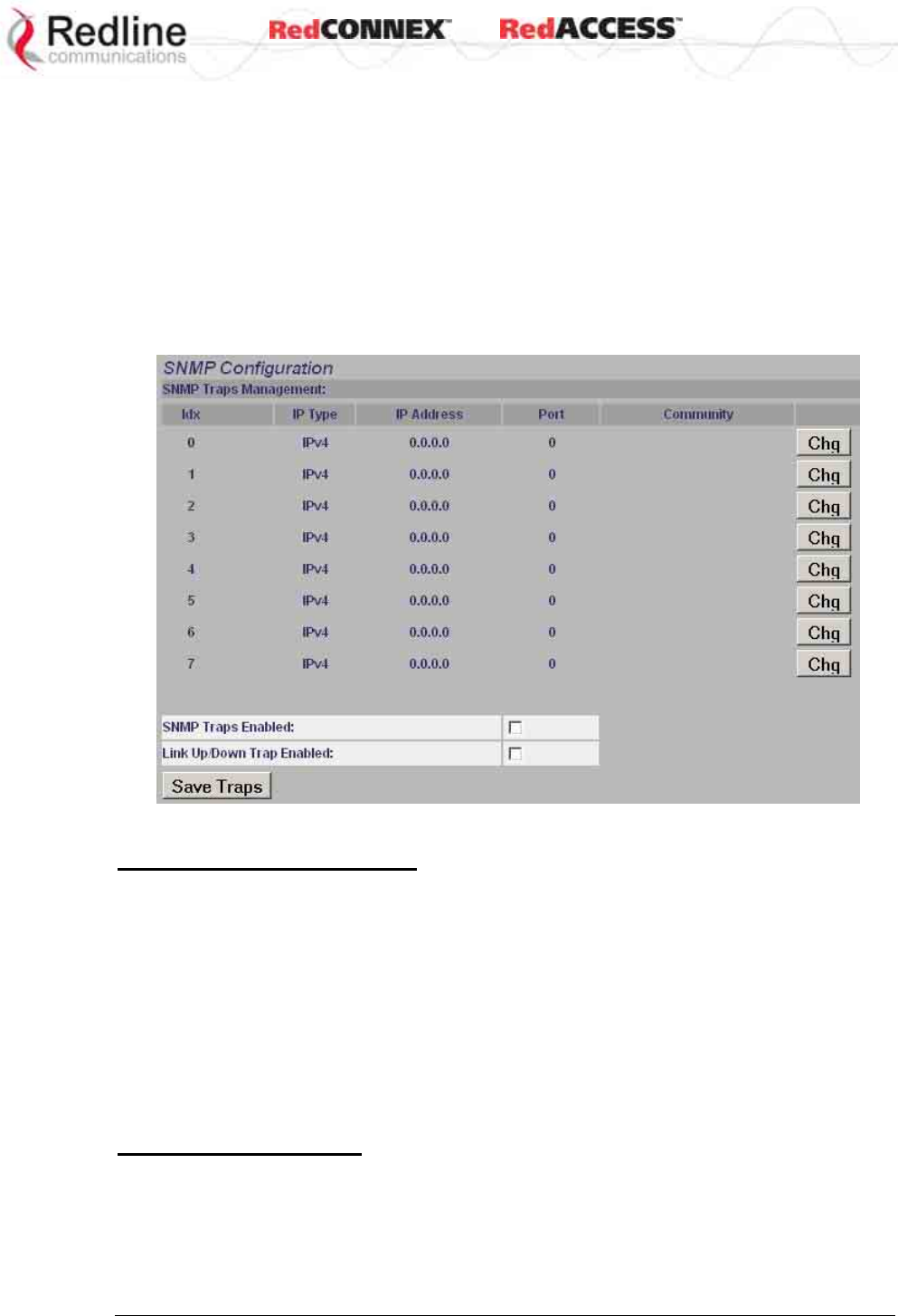
& User
AN-80i
Manual
70-00072-01-07 Proprietary Redline Communications © 2008 Page 43 of 106 Sept 18, 2008
3.10 SNMP Settings Screen
Click Configure SNMP (blue text) on the System Configuration screen to view and edit the
SNMP settings. The hyperlink appears only if the SNMP Enable box is checked.
The SNMP protocol allows an application to interrogate the AN-80i for information saved
in the MIB an to change enabled fields within the MIB. When the SNMP Agent in the AN-
80i detects an error condition, a special message known as a trap can be sent (if
enabled). A Trap Host is an IP system/server that is set up to receive SNMP trap
messages. The SNMP Configuration screen displays a list of the current communities.
The Chg buttons can be used to add, edit, or delete community settings.
Figure 17: Web - SNMP Configuration Screen
SNMP Community Management
Community Name: Displays the SNMP community name for each entry (maximum of
eight entries).
Access: Displays the access permissions for each SNMP community.
None: Deny read and write permission for this community.
Read: Grant read access permission only for this community. Deny write permission.
Write: Grant write access permission only for this community. Deny read permission.
Read&Write: Grant read and write access permission for this community.
Chg: Click the Chg button to modify the settings for the adjacent entry.
Save Comm: Click the Save Comm button to save changes to the community settings.
SNMP Traps Management
IP Address(IPv4): IP address associated with this SNMP alarm.
Port: Destination port address associated with this SNMP alarm.
Community: Community associated with this SNMP alarm.
Chg: Click the Chg button to modify the settings for the adjacent entry.
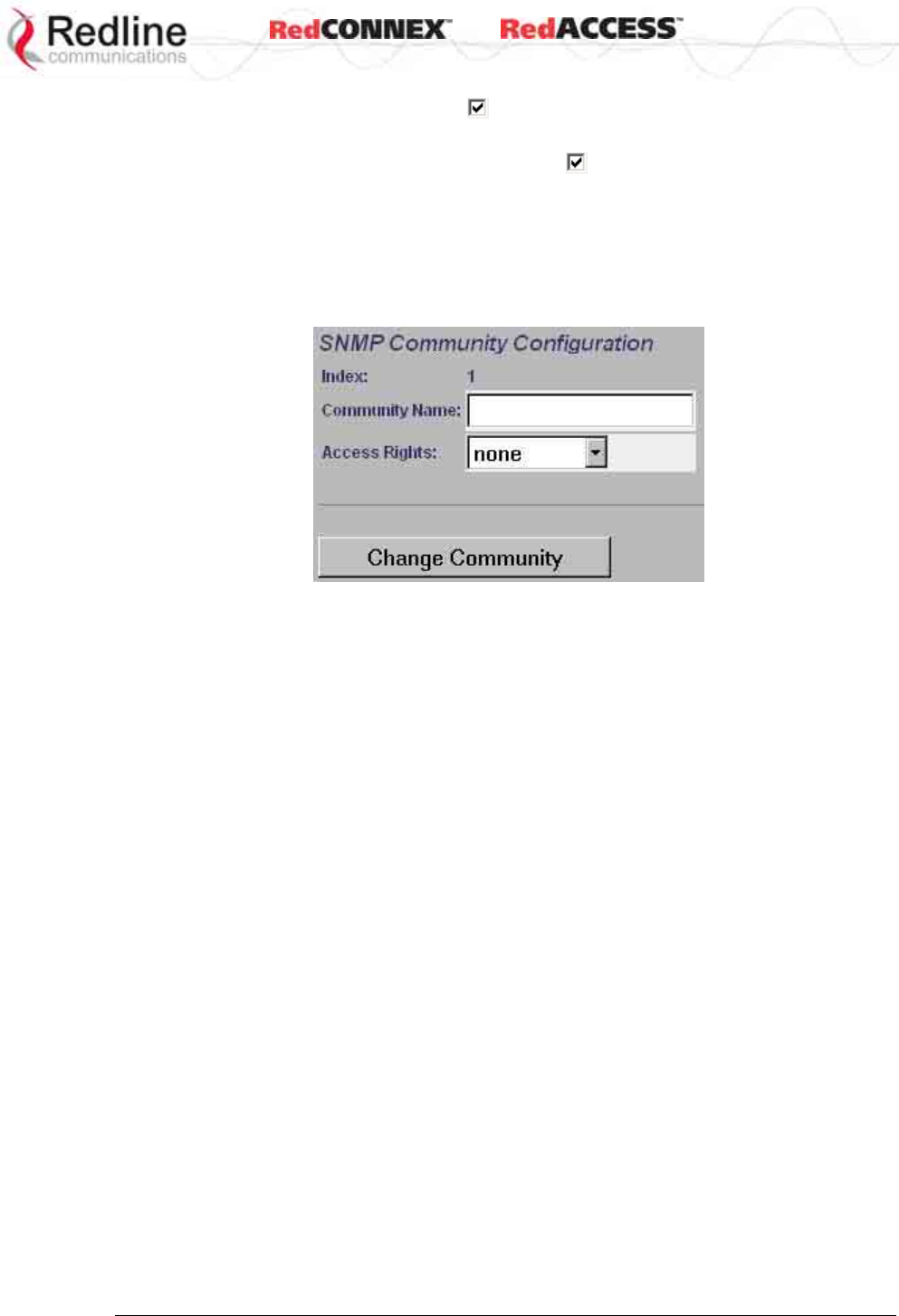
& User
AN-80i
Manual
70-00072-01-07 Proprietary Redline Communications © 2008 Page 44 of 106 Sept 18, 2008
SNMP Traps Enabled: Check this box to enable SNMP traps to be sent. If the box is
not checked, all SNMP traps are disabled.
Link Up/Down Trap Enabled: Check this box to enable an SNMP trap to be
generated for each link up and link down event.
Save Traps: Click the Save Traps button to save changes to the SNMP trap settings.
3.10.1 Change SNMP Community
Each entry in the SNMP Community Management table may be changed individually.
Click the Chg button adjacent to any entry to modify the settings.
Figure 18: Web - SNMP Community Configuration Screen
Index: Display the unique reference number for this entry.
Community Name: Enter or modify the SNMP community name for this entry.
Access Rights: Select the access permissions for this entry.
None: Deny read and write permission for this entry.
Read: Grant read access permission only for this entry. Deny write permission.
Write: Grant write access permission only for this entry. Deny read permission.
Read&Write: Grant read and write access permission for this entry.
Change Community: Click the Change Community button to copy these settings to the
community settings table. This action does not permanently save changes. To save
changes to the community settings you must also click the Save Comm button in the
SNMP Configuration screen.
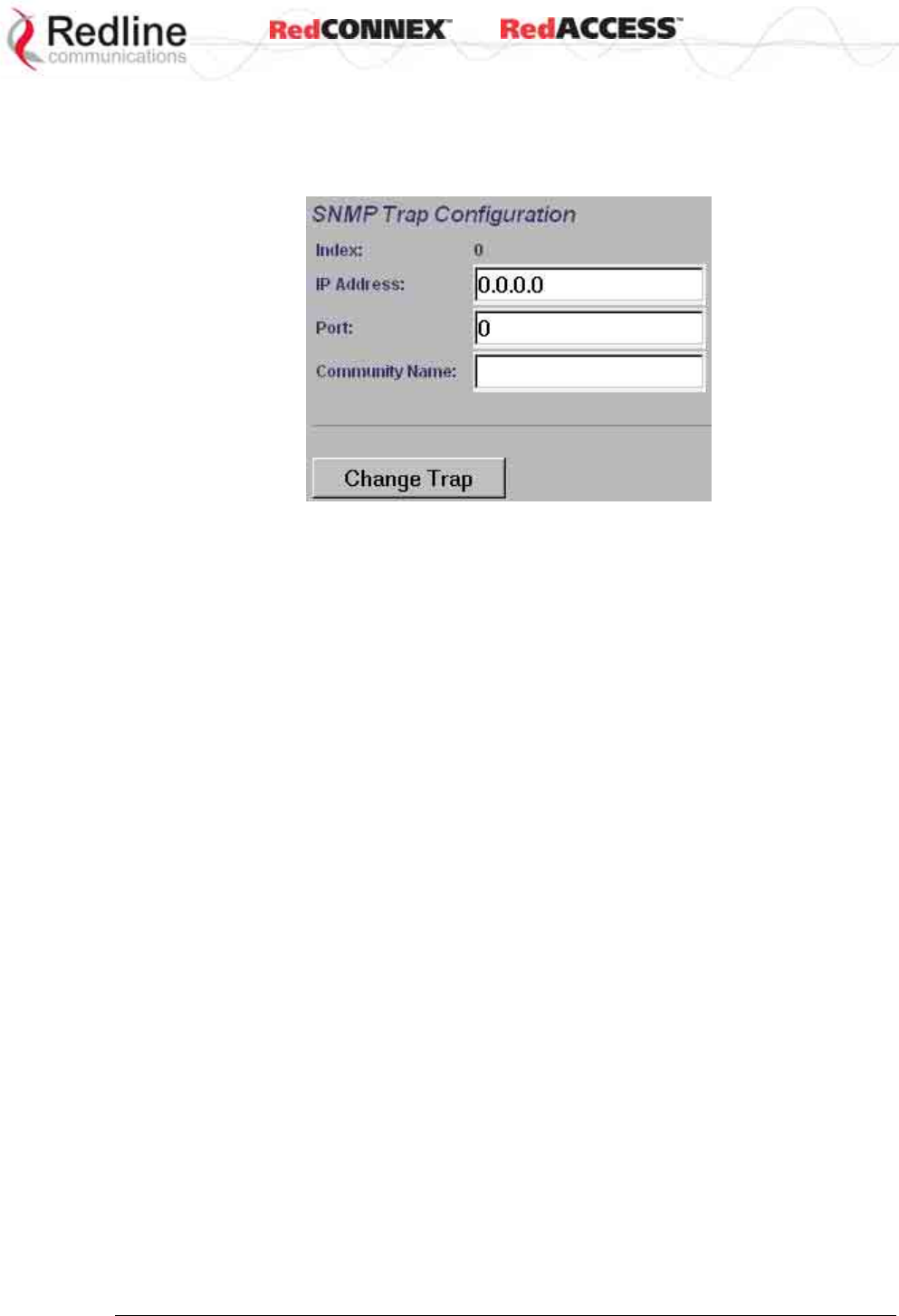
& User
AN-80i
Manual
70-00072-01-07 Proprietary Redline Communications © 2008 Page 45 of 106 Sept 18, 2008
3.10.2 Change SNMP Trap Configuration
Each of the eight entries in the SNMP Traps Management table may be changed
individually. Click the Chg button to modify the settings for the adjacent entry.
Figure 19: Web - SNMP Trap Configuration Screen
Index: Display the table position number for this entry. Position 0 is the first entry.
IP Address: Enter the IP address (IPv4) associated with this SNMP alarm.
Port: Enter the destination port address associated with this SNMP alarm.
Community Name: Enter the SNMP community name for this entry.
Change Trap: Click the Change Trap button to copy these settings to the community
settings table. This action does not permanently save changes. To save changes to the
SNMP trap settings you must click the Save Traps button in the SNMP Configuration
screen.
& User
AN-80i
Manual
70-00072-01-07 Proprietary Redline Communications © 2008 Page 46 of 106 Sept 18, 2008
3.11 Spectrum Sweep
Click Spectrum Sweep in the left hand menu to display the Spectrum Sweep configuration
screen. The spectrum sweep feature is an off-line RF survey tool to detect interference
and evaluate spectrum availability. Configurable survey parameters include the high and
low frequency limits, the step size, and the number of samples at each step. The output
graph displays the maximum (red) and average (blue) RSSI for each step.
Figure 20: Web - Spectrum Sweep Screen
Start Frequency (MHz): Enter center frequency of the lowest channel to be scanned.
See Table 63: Spec. - Regional Identification Codes on page 99.
End Frequency (MHz): Enter center frequency of the highest channel to be scanned.
See Table 63: Spec. - Regional Identification Codes on page 99.
Step (MHz): Enter the frequency step (MHz) to use when scanning from the lowest to
the highest frequency. The step selection must be a multiple of 2.5 MHz (i.e., 2.5, 5, etc).
No. of acquisitions: Enter the number of times the frequency will be sampled at each
step. The recommended range is 10 to 100 samples. When a potentially clear channel is
identified, reduce the frequency range and step size while increasing the sample size to
monitor the channel over a longer period.
Start: Left-click the Start button to begin the scan.
Performing a Sweep
The PTP Master or PMP Sector Controller transmitter is automatically disabled during
the spectrum scan. If the scan is being performed from a PTP Slave or PMP Subscriber,
the transmitter on the remote AN-80i for this link should be disabled for the duration of
the test. Use the configuration Test feature (system configuration screen) to remotely
(over-the-air) disable the remote transmitter for 5 minutes (uncheck the Radio Enable
field) and then recover automatically.
& User
AN-80i
Manual
70-00072-01-07 Proprietary Redline Communications © 2008 Page 47 of 106 Sept 18, 2008
Table 14: Web - Performing a Spectrum Sweep
Setting Description
System Mode:
PTP Slave / PMP
Subscriber
No action required: Remote end will remain passive during sweep.
System Mode:
PTP Master /PMP
Sector Controller
Use Web/CLI to disable radio on remote-end. Use 'test' function to
save and remote end will restore radio operation automatically after
5 minutes.
Figure 21: Web - Spectrum Sweep Results
& User
AN-80i
Manual
70-00072-01-07 Proprietary Redline Communications © 2008 Page 48 of 106 Sept 18, 2008
Chapter
4
4
4
P
PM
MP
P
O
Op
pe
er
ra
at
ti
io
on
n
4.1 Introduction
This section describes only the additional parameters required for configuring PMP
support, and an overview about defining and using VLAN and pass-through groups.
The AN-80i PMP software provides the following main features:
- IEEE 802.1Q standard compliance
- VLAN Groups span subscribers
- Multiple VLAN Connections per subscriber
- Multiple TLS transport based on VLAN ID classification
- QoS provisioning with individual CIR setting per connection
- VLAN trunking with tag insert/delete/re-map
- VLAN tagged management traffic
4.2 PMP Menu
The following menu items are available for configuring and monitoring the PMP
functions. See Table 13: Web - Default System Users on page 40 for the factory default
usernames and passwords.
Figure 22: PMP - Main Menu
& User
AN-80i
Manual
70-00072-01-07 Proprietary Redline Communications © 2008 Page 49 of 106 Sept 18, 2008
4.3 Functional Description
4.3.1 Overview
The AN-80i can operate as a VLAN-aware wireless switch, as a standard wireless bridge
(pass-through mode), or a combination of both. The following figure illustrates a simple
pass-though configuration. This configuration does not use VLAN tagging or filter the
Ethernet traffic.
Figure 23: PMP - Basic Pass-through Group Configuration
The following diagram illustrates a network implementation using two VLAN groups. The
packets tagged with VID=107 are classified as data traffic, while the packets tagged with
VID=108 are classified as voice traffic.
Figure 24: PMP - VLAN Tagged Traffic Example
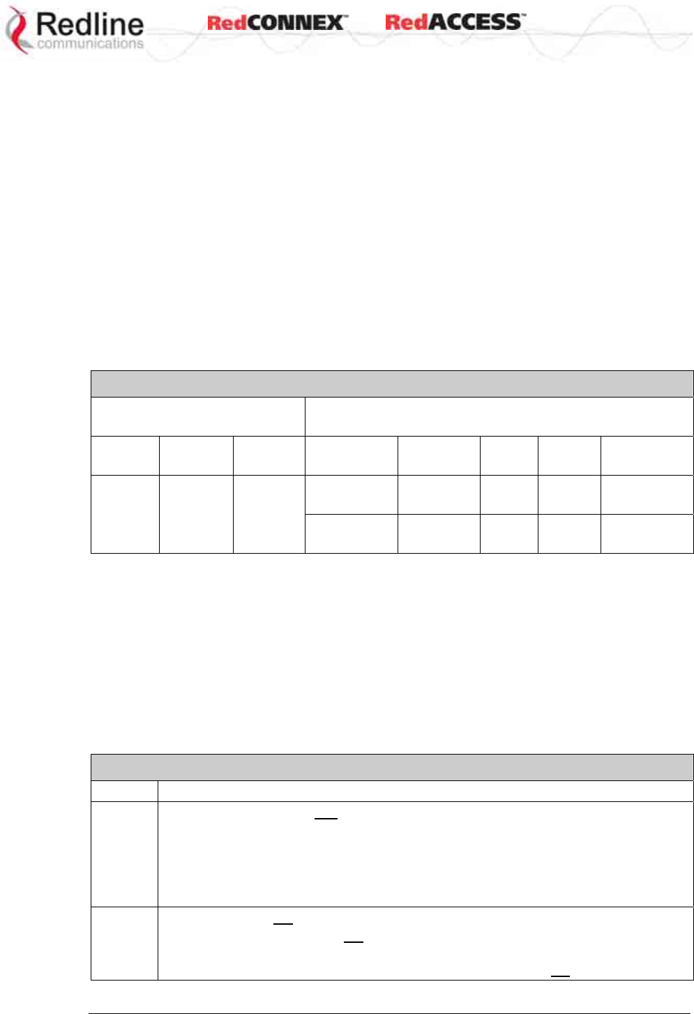
& User
AN-80i
Manual
70-00072-01-07 Proprietary Redline Communications © 2008 Page 50 of 106 Sept 18, 2008
4.3.2 Minimum Setup Requirements
A minimum set of parameters must be configured to enable data and management traffic
on any PMP deployment:
1. Create one or more Links to identify each subscriber in the sector, and set the
wireless link operating characteristics, including the maximum uplink and downlink
modulation.
2. Create one or more Groups (VLAN or pass-through) and set the operating
characteristics of this group.
3. Create one or more Connections (to Groups) for each subscriber, to assign
membership to at least one Group.
The following table provides a summary of the configuration shown in the pass-through
configuration diagram above. The actual Group ID and Link ID values are not available
until these items have been created during configuration of the system. This
configuration passes all data traffic as a standard PMP configuration.
Table 15: PMP - Basic Pass-Through Group Settings
Group Configuration
(Sector Controller) Connection Configuration
(Subscriber)
Group
Name Port
Tagging
Group
VID Connection
Name Port
Tagging
Link
ID
Group
ID
Connection
VID
SC-1 Pass
Through
NA SS-1 Pass
Through
[L-1] [SC-1] NA
SS-2 Pass
Through
[L-2] [SC-1] NA
Notes: 1. The Group ID, Conn ID, and Link ID values are assigned
automatically and must be read from the screen after items are created.
2. The QoS settings must be determined using the PMP Configuration
Tool.
4.3.3 Packet Classification
The AN-80i PMP deployment can be configured for use with VLAN tagged traffic,
untagged traffic, or a combination these two types. Ingress packets received on the
Ethernet port are classified into tagged or pass-through groups according to the criteria
in the following table. The Group settings apply to packets processed at the sector
controller, while Connection settings apply to packets processed at the subscriber.
Table 16: PMP - Packet Classification
Type Description
Tagged
Traffic
Packet has a VLAN tag and there is a Group/Connection configured for this VID.
Sector Controller: Packets are forwarded over the wireless link to all subscribers
with Connections to this VLAN Group.
Subscribers: Packets are forwarded to the sector controller. The sector
controller forwards the packets to the local Ethernet port and
subscribers with Connections to this VLAN Group.
Pass-
Through
Traffic
The packet does not have a VLAN tag, or no Group/Connection exists for this VID.
If a pass-through Group has not been defined, unclassified packets are discarded.
If a pass-through Group has been defined, classified packets are forwarded based
on the rules for tagged traffic. The packet VLAN information is not modified.
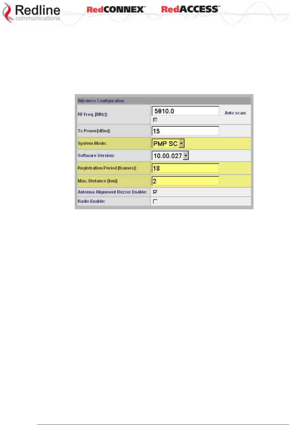
& User
AN-80i
Manual
70-00072-01-07 Proprietary Redline Communications © 2008 Page 51 of 106 Sept 18, 2008
4.4 PMP Screens
This section describes the configuration screens used to setup a PMP deployment.
4.4.1 Configuration Screen
Click Configure System in the menu to view and adjust configuration settings for general
system identification, Ethernet, and the wireless interface (partial screen shown below).
The highlighted wireless settings are specific to PMP deployments.
Figure 25: PMP - Wireless Settings
System Mode: The system designated as sector controller establishes and manages
the bi-directional data link with a remote end AN-80i. Only one system in a wireless link
must be set for Sector Controller mode.
PTP Sector Controller: AN-80i begins transmitting automatically, sends poll
messages to locate remote AN-80i subscribers, and negotiates operating settings for
the link.
PTP Subscriber: AN-80i waits passively, monitoring the selected channel(s) until
polled by the PTP Sector Controller.
Registration Period: The polling period for detecting new subscribers. Period is based
on the number of wireless frames transmitted. Permitted values are 1 to 400. The
recommended default registration period is 4.
Max. Distance [km]: Enter the distance to the subscriber located farthest away from the
sector controller (outer boundary of sector). This parameter is used to optimize
communications with the subscribers.
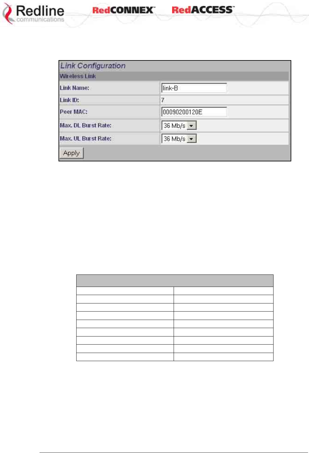
& User
AN-80i
Manual
70-00072-01-07 Proprietary Redline Communications © 2008 Page 52 of 106 Sept 18, 2008
4.4.2 Link Screen
Click New Link in the menu to add a new subscriber and choose the wireless parameters.
Figure 26: PMP - Link Configuration Screen
Link Name: Enter a name for this Link (15 characters max.). This Link name is displayed
with the Link ID on information and statistics screens.
Link ID: (Read only) A unique Link ID is generated automatically when a new link is
added.
Peer MAC: Enter the MAC address of the subscriber station. The sector controller only
registers a subscriber station if the MAC address has been entered using the link
configuration screen.
Max. DL Burst Rate: Select the downlink burst rate for unicast traffic from the sector
controller to the subscriber (based on link budget calculations).
Max UL Burst Rate: Select the uplink burst rate for unicast traffic from the subscriber to
the sector controller (based on link budget calculations).
Table 17: PMP Maximum Achievable UBR
Uncoded Burst Rate (Mbps) SINADR (dB)
54 25
48 23
36 18
24 15
18 11
12 9
9 9
6 7
& User
AN-80i
Manual
70-00072-01-07 Proprietary Redline Communications © 2008 Page 53 of 106 Sept 18, 2008
4.4.3 Group Screen
Click New Group in the left-hand menu to display a blank Group configuration screen. The
Group configuration defines how Ethernet packets are handled on the sector controller. A
Group must be created for each VLAN to be transported across the wireless interface.
Figure 27: PMP - Group Configuration Screen
Group
Group Name: Enter a name for this Group (15 characters max.). The Group name is
displayed on configuration and statistics screens.
Group ID: (Read only) A unique Group ID is generated automatically when a new Group
is created. The Group ID number is required when associating Connections to this Group.
Group Tagging Mode: Select the packet processing performed at the sector controller.
Packets are forwarded unicast (known address) or multicast (unknown address). Further
processing is performed at the subscriber based on the Connection configuration.
Tagged: Select tagged to associate a unique VID with this Group.
Packet received at sector controller Ethernet interface:
A packet with this VID has the matching (outermost only) VLAN tag removed. The
packet is forwarded over the wireless to all subscribers in this Group.
Packet received at sector controller wireless interface (from subscriber):
The packet belonging to this Group is forwarded unmodified over the wireless to all
subscribers belonging to this Group.
If the sector controller Ethernet port is enabled, a VLAN tag is added (outermost) and
set to the VID (Group VLAN ID field) for this Group and the packet is forwarded to the
sector controller Ethernet Port.
Pass-through: Select pass-through to create a Group to process all packets that do
not have a VLAN ID, or the outermost VLAN ID tag does not match the VLAN ID for
any Group. Only one pass-through Group can be defined for each sector controller. If

& User
AN-80i
Manual
70-00072-01-07 Proprietary Redline Communications © 2008 Page 54 of 106 Sept 18, 2008
a pass-through Group is not configured, all untagged packets received at the sector
controller Ethernet ingress port are discarded.
Packet received at sector controller Ethernet interface: The packet is forwarded
unmodified over the wireless to all subscribers in this Group.
Packet received at sector controller wireless interface (from subscriber): The packet
is forwarded unmodified over the wireless to all subscribers in this Group.
If the sector controller Ethernet port is enabled, the packet is also forwarded to the
sector controller Ethernet port.
Group VLAN ID: Enter the VID associated with this Group definition.
This field is used only when 'Tagged' is selected in the Group Tagging Mode field.
Default Priority: Enter the default 802.1p priority setting.
The default priority setting is used only when the Group Tagging Mode is set to 'pass-
through' mode and the associated Connection Tagging Mode is set to 'Tagged'. The Group
Default Priority value is used when adding the 802.1Q tag (Connection VLAN ID) to the
packet being forwarded.
SC Ethernet Enable: Controls the sector controller Ethernet port.
Check this box to allow ingress and egress data traffic on the sector controller
Ethernet interface. Uncheck this box ( ) to block all data traffic on the sector controller
Ethernet interface. The sector controller Ethernet port remains available for management
traffic.
SS To SS Multicast Enable:
Check this box to enable group multicast traffic between subscribers.
Uncheck this box ( ) to block all multicast traffic between subscribers.
Wireless Traffic Parameters
Changes to these settings affect the CIR and PIR for all groups and connections on the
wireless link.
Group QoS Level: This setting represents the range of CIR available to Group members
for downlink multicast/broadcast traffic.
It is strongly recommended to calculate the Group QoS Level using the Redline AN-80i
PMP Configuration Tool -- the Group QoS level can be read from the QoS column in the
Group ID Configuration section. To manually determine this setting, identify the member
Link having the lowest UBR and calculate the Group QoS Level using the formula: Burst
Rate - 1. A zero setting disables all DL broadcast and multicast traffic for this group.
Rate: Enter the maximum downlink burst rate for this Group.
It is recommended to use the 'auto' setting where the AN-80i selects the most reliable
rate. To manually determine this value, identify the Group member having the lowest DL
burst rate, and then set the Rate using the formula: Max DL Burst Rate - 1. For applications
requiring a higher broadcast/multicast rate (e.g., video), a higher setting can be used at
the risk of less reliable retransmissions.
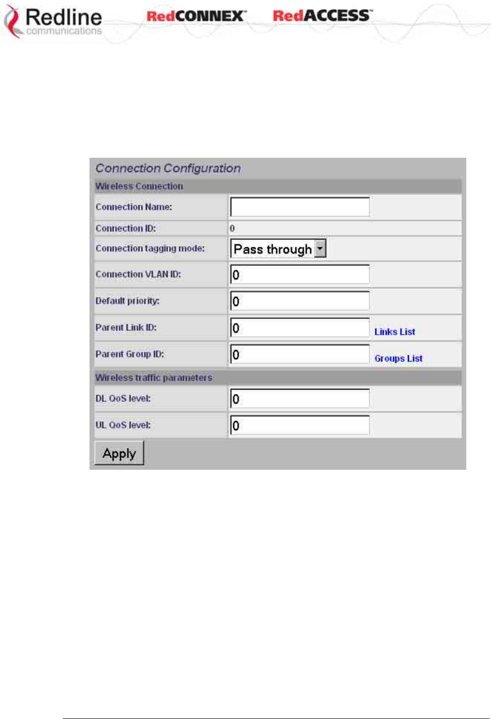
& User
AN-80i
Manual
70-00072-01-07 Proprietary Redline Communications © 2008 Page 55 of 106 Sept 18, 2008
4.4.4 Connection Screen
Click New Connection in the left-hand menu to display a blank Connection configuration
screen. To view an existing Connection, click Groups or Links, and then click Expand to
display the Connections for that Group/link, and then click Config for the desired
Connection. At least one Connection must be created for each VLAN to be transported
across the wireless switch. The Connection configuration defines how Ethernet packets
are handled on the subscribers. Each subscriber can participate in multiple VLANs.
Figure 28: PMP - Connection Configuration Screen
Connection Configuration
Connection Name: Enter a name for this Connection (15 characters max.). The
Connection name is displayed on configuration and statistics screens.
Connection ID: (Read only) A unique Connection ID is generated automatically when a
new link is created. The Connection ID number is required when assigning this Connection
to a Group.
Connection Tagging Mode: Select the packet processing at the subscriber.
Tagged: Select tagged to associate a unique VID with this Connection. Further
processing is performed at the sector controller based on the Group configuration
associated with this Connection.

& User
AN-80i
Manual
70-00072-01-07 Proprietary Redline Communications © 2008 Page 56 of 106 Sept 18, 2008
Packet received at subscriber Ethernet interface:
Each packet with this VID (Connection VLAN ID field) has the matching VLAN tag
(outermost only) removed and is forwarded over the wireless interface to the sector
controller.
Packet received at subscriber wireless interface (from sector controller):
A VLAN tag is added (outermost) and set to the VID (Connection VLAN ID field) for
this Connection. The packet is forwarded to the subscriber Ethernet port.
Pass-through: Select pass-through to create a Connection to process all untagged
packets and packets where the outermost VLAN ID tag does not match the VID
(Connection VLAN ID field) for with this Connection. Only one pass-through Connection
can be defined for each subscriber. If a pass-through Group is not configured, all
untagged packets received at the subscriber Ethernet ingress port are discarded.
Packet received at subscriber Ethernet interface:
The packet is forwarded unmodified over the wireless to the sector controller.
Packet received at subscriber wireless interface (from sector controller):
The packet is forwarded unmodified to the subscriber Ethernet port.
Connection VLAN ID: Enter the VLAN ID tag associated with this Connection definition.
This field is used only when 'Tagged' is selected in the Connection Tagging Mode field.
Default priority: Enter the default 802.1p priority setting.
The default priority setting is used only when the Connection Tagging is set to 'pass-
through' mode and the associated Group Tagging Mode is set to 'Tagged'. The
Connection Default Priority value is used when adding the 802.1Q tag (Group VLAN ID) to
the packet being forwarded.
Parent Link ID: Enter the Link ID for this Connection. This is the unique identification
value created automatically when the subscriber Link was added. See Links List below.
Links List: Click this text (right side of screen) to display a list of existing Link IDs.
Parent Group ID: Enter the Group ID for this Connection. This is the unique identification
value created automatically when the subscriber Link was added. See Groups List below.
Groups List: Click this text (right side of screen) to display a list of existing Group IDs.
Wireless Traffic Parameters
The sector controller allocates bandwidth for all subscribers using the Weighted Round
Robin algorithm with the combined total of all QoS levels acting as weights. The
aggregate QoS settings affect packet delay and jitter values for the entire sector.
It is strongly recommended to calculate DL QoS and UL QoS levels using the Redline AN-
80i PMP Configuration Tool -- the QoS levels for each Connection can be read directly
from the QoS column in the Connection ID Configuration section. To manually determine
these settings, identify the maximum UL and DL burst rate for the associated Link and
calculate the highest available level using the formula: Burst Rate - 1.
DL QoS Level: Enter the QoS level for downlink unicast traffic for this connection.
UL QoS Level: Enter the QoS level for uplink unicast traffic for this connection.
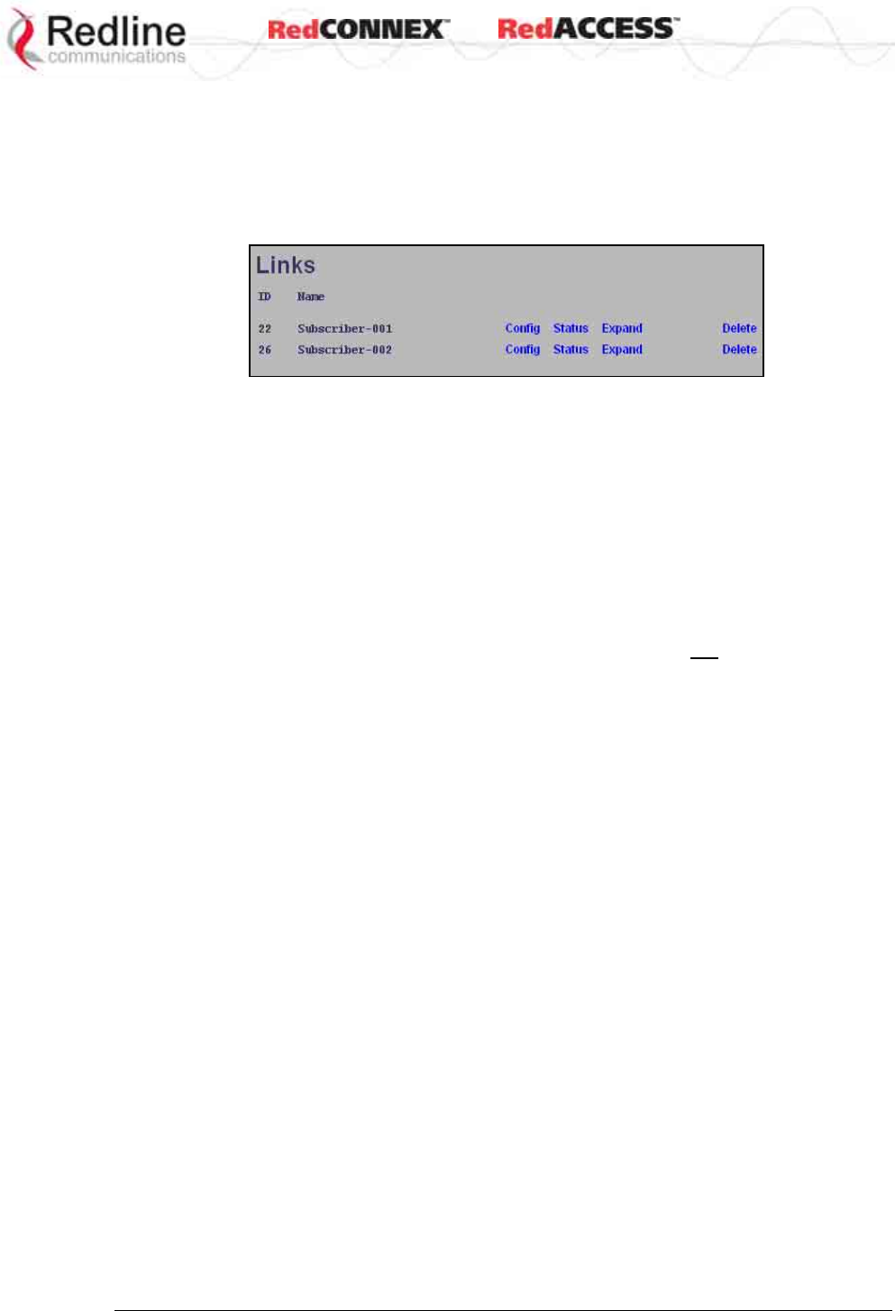
& User
AN-80i
Manual
70-00072-01-07 Proprietary Redline Communications © 2008 Page 57 of 106 Sept 18, 2008
4.5 Browse Screens
4.5.1 Links Screen
Click Links in the menu to display the links browse screen. This is a list of all configured
wireless links.
Figure 29: PMP - Links Browse Screen
ID: Unique number identifying each link.
Name: User-assigned name for each link.
Config: Click Config on any line to display the Link Configuration screen associated with
that Link.
Status: Click Status on any line to display the Link Statistics screen associated with that
Link. This includes uplink and downlink statistics for the link.
Expand: Click Expand on any line to display the Connections browse screen showing all
Connections associated with that Link.
Delete: Click Delete on any line to delete that Link. A link can not be deleted until all
Connections referencing this link are deleted.
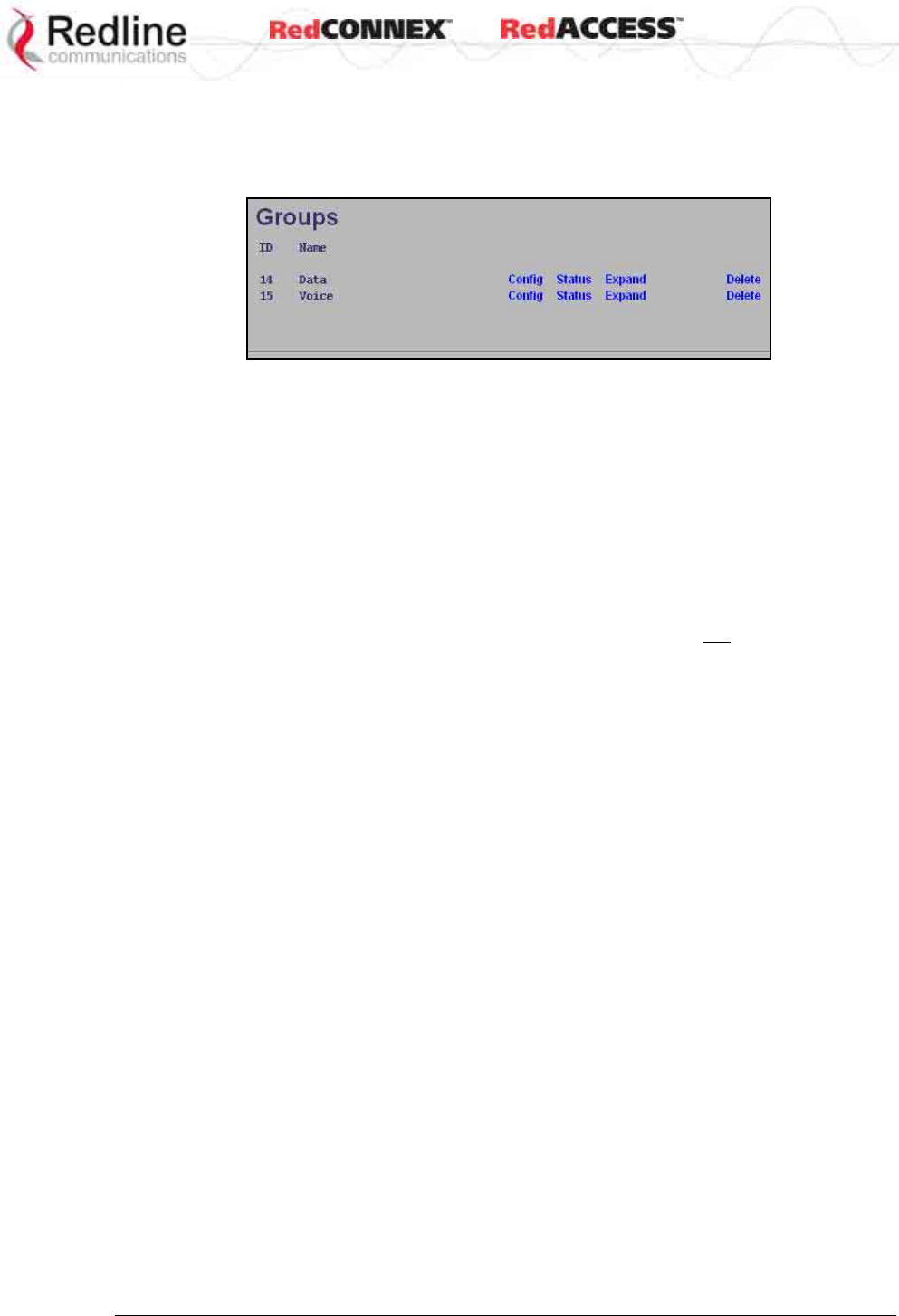
& User
AN-80i
Manual
70-00072-01-07 Proprietary Redline Communications © 2008 Page 58 of 106 Sept 18, 2008
4.5.2 Groups Screen
Click Groups in the menu to display the Groups browse screen. This is a list of all
configured Groups.
Figure 30: PMP - Groups Browse Screen
ID: Unique number identifying each Group.
Name: User-assigned name for each Group.
Config: Click Config on any line to display the Group Configuration screen associated with
that Group.
Status: Click Status on any line to display the Group Statistics screen associated with that
Group. This includes uplink and downlink statistics for the Group.
Expand: Click Expand on any line to display the Connections browse screen showing all
Connections associated with that Group.
Delete: Click Delete on any line to delete that Group. A Group can not be deleted until all
Connections referencing this Group are deleted.
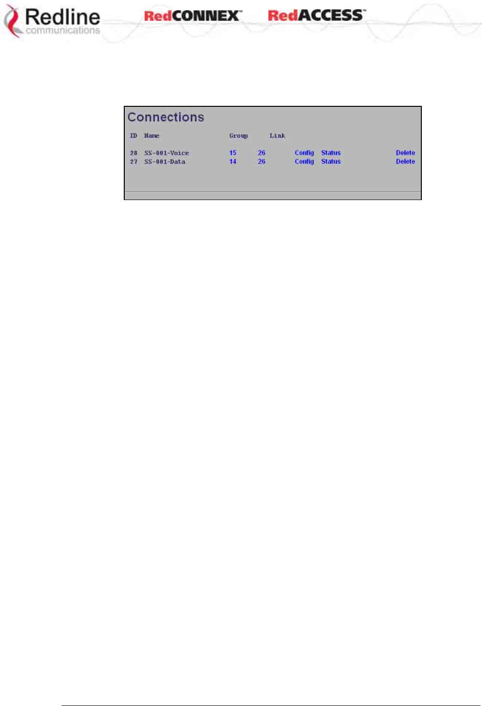
& User
AN-80i
Manual
70-00072-01-07 Proprietary Redline Communications © 2008 Page 59 of 106 Sept 18, 2008
4.5.3 Connections Screen
The Connections browse screen is accessible only from the Groups or Links browse
screens. Click Groups or Links in the menu and then click Expand for any Group or Link.
Figure 31: PMP - Connections Browse Screen
ID: Unique number identifying each Connection.
Name: User-assigned name for each Connection.
Group: Click the Group number (i.e., 4) on any line to display the Group associated with
this Connection.
Link: Click the link number (i.e., 5) on any line to display all Connections configuration for
that link.
Config (Configure): Click Config on any line to display the Link configuration screen for
that item.
Status (Statistics): Click Status on any line to display uplink and downlink statistics for
that Connection.
Expand: Click Expand on any line to display the Connections browse screen.
Delete (Delete): Click Delete on any line to delete that Connection.
& User
AN-80i
Manual
70-00072-01-07 Proprietary Redline Communications © 2008 Page 60 of 106 Sept 18, 2008
4.6 Statistics Screens
4.6.1 Link Statistics
The Link Statistics screen is accessible only from the Links browse screen. Click Links in
the menu and then click Status to display the statistics screen.
Figure 32: PMP - Link Statistics Screen
General
Link Name: User-assigned name for this link.
Link ID: Unique number identifying this link.
Peer MAC: MAC Address of the subscriber.
Active: Indicates if wireless link is operational (Active=YES).
Link Up Time: Total time the wireless link has been operational.
Link lost Count: Number of times link has been out of service.
Status Code: Code indicating the condition of the AN-80i system. Status indications are
specific for PMP and PTP operation.
Configured Connections: The number of Connections configured on this link.
Wireless
The following statistics are displayed for both uplink and downlink.
Burst Rate: The current uncoded burst rate for the link.
RSSI: RSSI measured since the last screen refresh.
SINADR: Average signal to interference, noise, and distortion ratio measured since the last
screen refresh.
Lost Frames: Number of frames lost.
& User
AN-80i
Manual
70-00072-01-07 Proprietary Redline Communications © 2008 Page 61 of 106 Sept 18, 2008
Blocks
Blocks Total: Total number of blocks retransmitted over the wireless interface.
Blocks Retransmitted: Number of blocks retransmitted over the wireless interface.
Blocks Discarded: Number of blocks discarded (could not be sent over the wireless).
Controls
Refresh: Click Refresh to update the statistics display.
Reset Statistics: Click this button to zero the counters for the wireless and Ethernet LAN
Statistics displayed on this page.
4.6.2 Group Statistics
Use the Group statistics screen to view statistics for all downlink traffic on Connections to
this Group. Click Groups in the menu to display the Groups browse screen. Click Status to
display downlink statistics for the selected Group.
Figure 33: PMP - Group Statistics Screen
General
Group Name: Name assigned to this Group.
Group ID: Unique numeric identifier for this Group.
Packet (Downlink)
Packets Discarded: Number of Ethernet packets discarded (could not be sent over the
wireless interface).
Packets Transmitted: Number of Ethernet packets transmitted over the wireless interface.
Packets Received: Number of Ethernet packets received over the wireless interface.
Controls
Reset: Click Reset to zero the statistics values.
Refresh: Click Refresh to update the statistics display.
& User
AN-80i
Manual
70-00072-01-07 Proprietary Redline Communications © 2008 Page 62 of 106 Sept 18, 2008
4.6.3 Connection Statistics
Use the Connection statistics screen to view statistics for all uplink and downlink traffic on
the selected Connection. Click Groups in the menu to display the Groups browse screen.
Click Expand to display a list of Connections. Click Status to display statistics for the
selected Group.
Figure 34: PMP - Connection Statistics Screen
General
Name: Name assigned to this Connection.
ID: Unique numeric identifier for this Connection.
Packet
Packets Discarded: Number of Ethernet packets discarded (could not be sent over the
wireless interface).
Packets Transmitted: Number of Ethernet packets transmitted over the wireless interface.
Packets Received: Number of Ethernet packets received over the wireless interface.
Controls
Reset: Click Reset to zero the statistics values.
Refresh: Click Refresh to update the statistics display.
& User
AN-80i
Manual
70-00072-01-07 Proprietary Redline Communications © 2008 Page 63 of 106 Sept 18, 2008
4.6.4 System Status - PMP Wireless Statistics
Click System Status in the menu to view system, Ethernet statistics, and wireless
interface statistics. The sector controller status screen includes information about the
PMP deployment.
Figure 35: PMP - System Status Screen
Configured Stations: This is the number of Links defined (to subscribers).
Configured Connections: The number of Connections defined for all subscribers.
Active Wireless Links: The number of registered subscribers.
Active Wireless Connections: The number of connections to registered subscribers.
For all other statistics, refer to Wireless Statistics on page 26.
4.7 Quick Configuration Guide
This procedure is to aid configuring point-to-multipoint (PMP) operation on AN-80i
systems. For complete installation and operational procedures. refer to the AN-80i
System User Manual, the AN-80i Quick Install Guide, and the Installation Guidelines
provided on CD-ROM.
The VLAN tagging feature allows the user to configure and operate an AN-80i
deployment as a VLAN-aware wireless switch. A 'group' is created at the sector
controller for each VLAN to be transported, and 'connections' are added to enable data
flow with any subscriber station participating in that VLAN. If VLAN is not required, a
default group and set of connections must be setup to define the traffic characteristics.
Prior to completing this setup, no Ethernet data traffic can be transmitted over the
wireless interface.
The procedures provided below include steps to setup a basic working configuration for
initial testing, and then to introduce VLAN traffic controls.
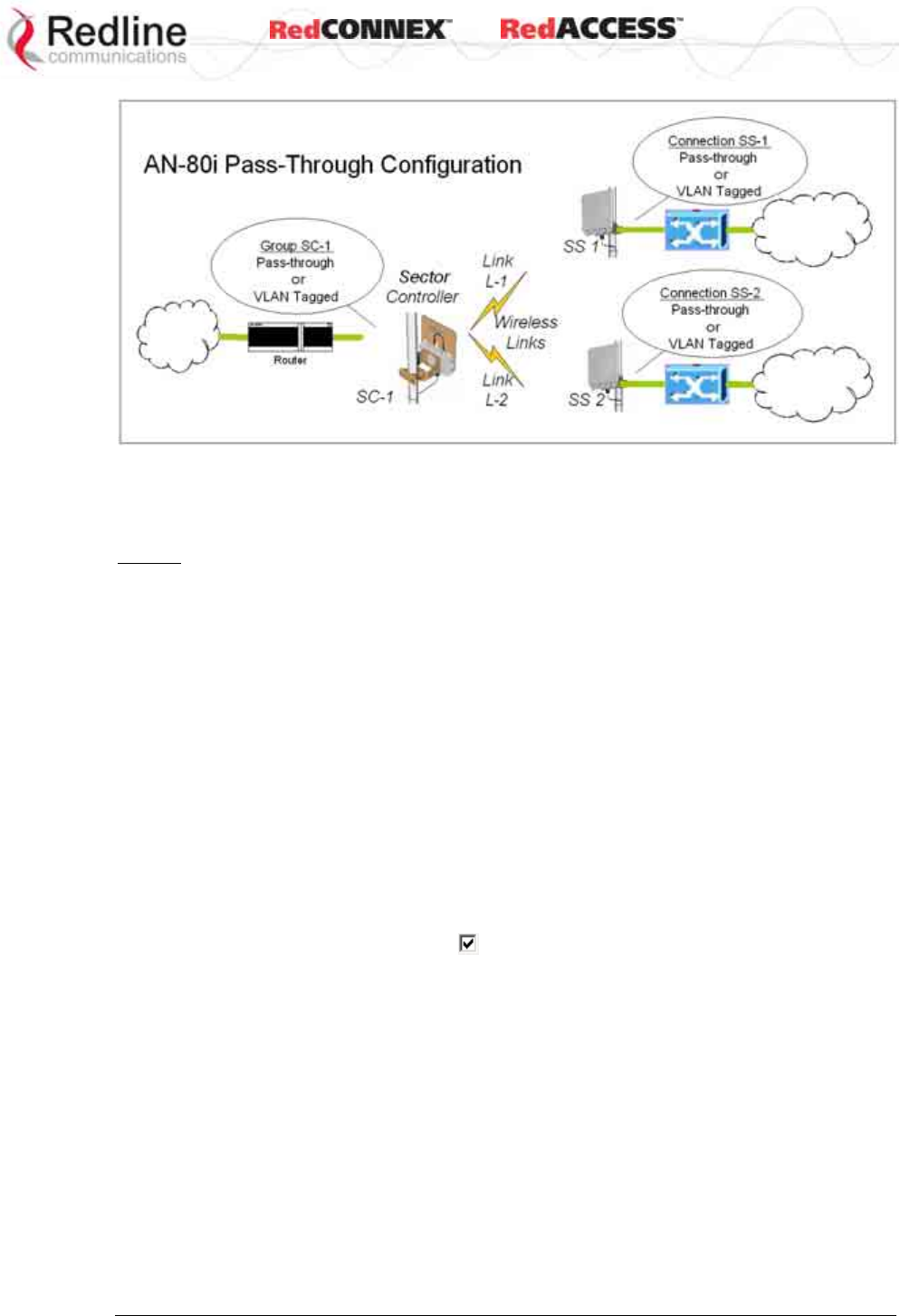
& User
AN-80i
Manual
70-00072-01-07 Proprietary Redline Communications © 2008 Page 64 of 106 Sept 18, 2008
Figure 36: PMP - Pass-through Only Deployment
4.7.1 Configure Pass-Through Operation
For initial installation and testing, it is recommended to setup a PMP configuration
without VLAN support. Use the following steps to configure a PMP pass-through link.
Step 1: Create New Link for Each Subscriber
1. Click New Link to display the Link Configuration screen.
2. Enter a unique name for this link in the Link Name field.
3. Enter the MAC address of the subscriber station in the Peer MAC field.
4. Enter the UBR for this link (based on link budget calculations).
5. Use the default values for all other fields.
6. Click the Apply button to save and activate these settings.
7. Repeat steps 1 - 6 for each subscriber station.
Step 2: Create Single Pass-through Group
1. Click New Group to display the Group Configuration screen.
2. Enter a unique name for this group in the Group Name field.
3. Set the Group Tagging Mode to Pass-through.
4. Check the SC Ethernet Enable box .
5. Set the Group QoS value for sending multicasts (i.e., 5). A value of zero (0) disables
all traffic.
6. Use the default values for all other fields.
7. Click the Apply button to save and activate these settings.
Step 3: Create Connections
1. Click New Connection to display the Connection Configuration screen.
2. Enter a unique name for this connection in the Connection Name field.
3. Set the Connection Tagging Mode to Pass-through.
4. Enter the Link ID of a subscriber station in the Link ID field.
5. Enter the Group ID in the Group ID field.
6. Set the DL QoS Level and UL QoS Levels. Default is 'MAX Burst Rate Value - 1'.
Setting the value to zero (0) disables all traffic.

& User
AN-80i
Manual
70-00072-01-07 Proprietary Redline Communications © 2008 Page 65 of 106 Sept 18, 2008
7. Click the Apply button to save and activate these connection settings.
8. Repeat steps 1 - 7 to add a connection for each subscriber station.
Step 4: Save Configuration
Click Save in the left-hand menu to permanently save all settings. The system will pass all tagged
and untagged data and management traffic.
The following table provides sample settings for a pass-though group at the sector controller and
connections to two subscriber stations.
Table 18: PMP - Basic Pass-Through Group Configuration Settings
Group Configuration (SC) Connection Configuration (SS)
Group
Name Group
Tagging
Mode
Group
VLAN
ID
Connection
Name Connection
Tagging
Mode
Link
ID
Group
ID
Connection
VLAN ID
SC-1 Pass
Through
NA SS-1 Pass
Through
[L-1]* [SC-1]* NA
SS-2 Pass
Through
[L-2]* [SC-1]* NA
*The group ID and link ID are numbers generated automatically by the AN-80i.
4.7.2 VLAN Configuration
Use these steps to convert the system from pass-through operation to VLAN tagged connections.
Step 1: Change Group to VLAN Tagged
1. Click Groups to display the Groups Configuration screen.
2. Click Config to edit the Group configuration.
3. Set the mode to Tagged in the Group Tagging Mode field.
4. Enter the VID for this group in the Group VLAN ID field.
5. Click the Apply button to save and activate these settings.
Step 2: Change Connections to VLAN Tagged
1. Click Groups in the menu to display the Groups Configuration screen.
2. Click Expand to view all connections for that Group.
3. Choose a connection and click Config to edit the Connection Configuration.
4. Set the mode to Tagged in the Connection Tagging Mode field.
5. Enter the VLAN ID for this connection in the Connection VLAN ID field.
6. Click the Apply button to save and activate these settings.
7. Repeat steps 1 through 6 for each Connection in the Group.
Step 3: Save Configuration
Click Save in the left-hand menu to permanently save and activate all settings. The system will
now pass only VLAN tagged traffic.

& User
AN-80i
Manual
70-00072-01-07 Proprietary Redline Communications © 2008 Page 66 of 106 Sept 18, 2008
Chapter
5
5
5
C
CL
LI
I
I
In
nt
te
er
rf
fa
ac
ce
e
This section describes the procedures for configuring and operating the AN-80i using
CLI over a Telnet Connection.
5.1 CLI Command Summary
All commands are case-sensitive. Use the following general format:
command <Enter>
Online help is available for all commands, and the Tab key can be used for auto-
complete functions. The following table lists all AN-80i commands available from root
mode (default mode when you login).
Table 19: CLI - Command Summary
PTP PMP Command Description
√ √ chgver Change default version of software and reboot.
√ clear Clear commands.
√ del Delete an ID.
√ enable Enable an ID.
√
freq Enter frequency ranges for autoscan and DFS.
√
generate Create DSA/RSA keys for SSH locally on AN-80i.
√ √ get Display the value of a statistic or parameter.
√ √ load Load commands.
√ logout End the current Telnet session.
√ new Create a new ID.
√
ping Send a ping message from the AN-80i system.
√
reboot Reboot the AN-80i.
√ √ reset Reset the AN-80i statistics values.
√ √ save Save the selected configuration settings.
√ script Generate a configuration script.
√ √ set View/modify a system parameter value.
√ √ show View system compound objects (i.e., configuration).
√ √ snmpcommunity View/modify the SNMP community settings.
√ √ snmptrap View/modify the SNMP trap settings.
√ √ test Activate edited changes to the system configuration for
a test period of five minutes.
√ √ upgrade Upload a software binary image to the AN-80i.
√ √ user View/modify the user/password configuration.
√
whoami Display login name for this Telnet session.
& User
AN-80i
Manual
70-00072-01-07 Proprietary Redline Communications © 2008 Page 67 of 106 Sept 18, 2008
Table 20: CLI - Root Mode Commands
PTP PMP Command Description
√ √ Tab When entering a command, hit the Tab key at any time to perform
auto-complete or view available options.
√ √ ? Use the '?' character to display help for any command or mode.
Example: From the root directory, enter the following command to
list all parameters that can be changed using the 'set' command:
set ?
√ √ CTRL-Z Return to root mode.
Cancel command entry (alternative to backspace delete).
√ √ exit
Return to parent node / mode.
all (exit all) Return to root mode.
√ √ logout Terminate this telnet session. May be entered from any mode.
5.2 Connecting with Telnet
To connect to the AN-80i, open a Telnet session to the IP address of the AN-80i. On a
Windows™ PC, open the Run command and type 'telnet' followed by the IP address of
the AN-80i. When the command prompt screen appears, login to the AN-80i. The AN-80i
may now be controlled using a set of CLI commands.
Figure 37: CLI - Connecting via Telnet
The system will logout users automatically if no commands are received (idle) for five
minutes. To exit immediately from the CLI, type the following command:
logout [ENTER]
The AN-80i supports two concurrent Telnet sessions. One session has full capabilities
and the second session is read-only (e.g., monitor or show parameter settings).
5.3 CLI Command Set
5.3.1 Chgver
Use the chgver command to change the software version loaded when the AN-80i is
rebooted.
Table 21: CLI - chgver
PTP PMP Parameter/Description
√ √ Enter this command to toggle between software versions. The setting will
alternate between the two banks of memory (no parameters).
chgver <Enter>
& User
AN-80i
Manual
70-00072-01-07 Proprietary Redline Communications © 2008 Page 68 of 106 Sept 18, 2008
5.3.2 Clear
Use the clear command to delete all IDs from an ID table.
Table 22: CLI - clear
PTP PMP Parameter/Description
√ Enter this command to delete all IDs from an ID table.
clear <idtable>
idtable - Clear all the IDs
5.3.3 Del
Use the del command to delete a specific ID or security key/certificate.
Table 23: CLI - del
PTP PMP Parameter/Description
√ del <id>
Remove a group, connection, or link id.
id number <integer>
Unique number for group, connection, or link.
√ Del <file>
file <name> <mode>
Remove a file from flash and runtime memory.
<name> File name on server. File name must be one of the
following:
dsa_key_<mac>.pem DSA key used for SSH.
rsa_key_<mac>.pem RSA Key used for SSH.
ssl_cert_<mac>.pem SSL Certificate.
ssl_key_<mac>.pem SSL Key.
usr_wcert_<mac>.der* User wireless certificate.
usr_wkey_<mac>.der* User wireless key.
usr_wacert_<mac>.der* User wireless authority
certificate
The <mac> portion is the MAC address of the board.
For example: dsa_key_00-09-02-00-01-02.pem
<mode> Can be 'usr' or 'factory'. Defaults to 'usr' if mode is not
specified.
*Not used in v3.00 software release.
5.3.4 Enable
Use the enable command to re-enable a specific ID (that was disabled).
Table 24: CLI - enable
PTP PMP Parameter/Description
√ enable
<id> - [id number]
& User
AN-80i
Manual
70-00072-01-07 Proprietary Redline Communications © 2008 Page 69 of 106 Sept 18, 2008
5.3.5 Freq
Use the freq command to configure frequency ranges when using autoscan or DFS.
Table 25: CLI - freq
PTP PMP Parameter/Description
√ freq
add Add a frequency range (up to 32 ranges).
<begin> - start frequency (MHz)
<end> - end frequency (MHz)
del Delete a frequency validation range
<index> - Frequency validation range index
print Print the list of frequency validation ranges.
Local frequency ranges:
<index> <begin> <end>
reload Reload the active list of frequency validation ranges.
5.3.6 Generate
Use the generate command to generate a DSA or RSA key for use with SSH.
Table 26: CLI - generate
PTP PMP Parameter/Description
√
generate sshkey <type>
Create keys of the specified type. The keys are saved in flash and runtime
memory.
<type> Can be dsa or rsa.
5.3.7 Get
Use the get command to view system parameters. Use the following general format to
view a parameter:
get [field] <Enter>
Table 27: CLI - get
PTP PMP Parameter/Description
√ calcdst: Calculated link distance between units.
√ √ erxpkt: Number of Ethernet packets received.
√ √ erxpktd: Number of Ethernet packets received that were discarded.
√ √ etxpkt: Number of Ethernet packets transmitted.
√ √ mac: AN-80i MAC address.
√ √ radiotype: Radio type.
√ √ rffreq: Current RF frequency setting.
√ rflink: Status of the RF link.
√ √ rfstatus: Status RF transmitter.
√ rssimax: Maximum RSSI.
√ rssimean: Mean RSSI.
√ rssimin: Minimum RSSI.

& User
AN-80i
Manual
70-00072-01-07 Proprietary Redline Communications © 2008 Page 70 of 106 Sept 18, 2008
Table 27: CLI - get
PTP PMP Parameter/Description
√ sinadr: Ration of signal to interference + noise.
√ √ swver: List the downloaded software versions.
√ √ sysuptime: Display the time since the last reboot.
√ √ txpower: Current Tx power setting.
√ ubrate: Current UBR value.
√ wrxpkt: Number of wireless packets received.
√ wrxpktd: Number of wireless packets received that were discarded.
√ wrxpktr: Number of wireless packets that were retransmitted.
√ wtxpkt: Number of wireless packets transmitted.
√ wtxpktd: Number of wireless packets transmitted that were discarded.
√ wtxpktr: Number of wireless packets that were retransmitted.
√ activeids: Number of active IDs.
√ activelinks: Number of the active links.
√ boardtype: Board type.
√ dldpkt: Downlink discarded packets counter.
√ dlrpkt: Downlink Rx packets counter.
√ dltpkt: downlink Tx packets counter.
√ idenable: ID status.
√ lactive: Link active status.
√ ldlblk: Downlink total blocks counter.
√ ldlbr: Downlink burst rate.
√ ldldblk: Downlink discarded blocks counter.
√ ldllfr: Downlink lost frames counter.
√ ldlrblk: Downlink retransmitted blocks counter.
√ ldlrssi: Downlink RSSI.
√ ldlsnr: Downlink SINADR.
√ llostc: Link lost Connection counter.
√ lrcon: Number of link registered Connections.
√ lscode: Link status code.
√ lulblk: Uplink total blocks counter.
√ lulbr: Uplink burst rate.
√ luldblk: Uplink discarded blocks counter.
√ lullfr: Uplink lost frames counter.
√ lulrblk: Uplink retransmitted blocks counter.
√ lulrssi: Uplink RSSI.
√ lulsnr: Uplink SINADR.
√ luptime: Link up-time.
√ regconn: Number of configured Connections.
√ regstations: Number of configured stations.

& User
AN-80i
Manual
70-00072-01-07 Proprietary Redline Communications © 2008 Page 71 of 106 Sept 18, 2008
Table 27: CLI - get
PTP PMP Parameter/Description
√ uldpkt: Uplink discarded packets counter.
√ ulrpkt: Uplink Rx packets counter.
√ ultpkt: Uplink Tx packets counter.
√ werxpkt: Wireless Eth Rx packets counter.
√ werxpktdis: Wireless Eth Rx discarded packets counter.
√ werxpkterr: Wireless Eth Rx packets with errors counter.
√ wetxpkt: Wireless Eth Tx packets counter.
√ wetxpktdis: Wireless Eth Tx discarded packets counter.
√ wetxpkterr: Wireless Eth Tx packets with errors counter.
5.3.8 Load
Use the load command to load an ID table from non-volatile memory.
Table 28: CLI - load
PTP PMP Parameter/Description
√ load idtable - Load all IDs from flash memory.
√ load file <server> <name> <mode>
Load saved security keys information from file on FTP server.
<server> IP address of the TFTP server. Files must be stored in the
TFTP server default download directory.
<name> File name on server. File name must be one of the
following:
dsa_key_<mac>.pem DSA key used for SSH.
rsa_key_<mac>.pem RSA Key used for SSH.
ssl_cert_<mac>.pem SSL Certificate.
ssl_key_<mac>.pem SSL Key.
usr_wcert_<mac>.der User wireless certificate.
usr_wkey_<mac>.der User wireless key.
usr_wacert_<mac>.der User wireless authority
certificate.
Where, <mac> is the MAC address of the board.
For example: dsa_key_00-09-02-00-01-02.pem
<mode> Defaults to 'usr' if mode is not specified.
run - Display keys currently in-use.
usr - Display the user-specified keys and certificates.
√ √ load script<server> <name>
Use the script command to load the AN-80i configuration information
from a file (created using script command) from a remote TFTP server.
The file must be located in the TFTP default directory.
<server> - [server IP address]
<name> - [script file name]
& User
AN-80i
Manual
70-00072-01-07 Proprietary Redline Communications © 2008 Page 72 of 106 Sept 18, 2008
5.3.9 Logout
Use the logout command to terminate the current Telnet session.
Table 29: CLI - logout
PTP PMP Parameter/Description
√ new Terminate the current Telnet session.
5.3.10 New
Use the new command to create a new link, group, or connector ID.
Table 30: CLI - new
PTP PMP Parameter/Description
√ new
<id_type> - [link | group | conn]
<id> - <id number>
5.3.11 Ping
Use the ping command to initiate an ICMP ping command from the AN-80i.
Table 31: CLI - ping
PTP PMP Parameter/Description
√ ping
<address> - Target IP address
<count> - Number of ICMP packets to send [1..16].
5.3.12 Reboot
Use the reboot command to reboot the AN-80i.
Table 32: CLI - reboot
PTP PMP Parameter/Description
√ √ reboot <seconds> Time to reboot the AN-80i.
<seconds> Time in seconds (0 cancels previous reboot command).
5.3.13 Reset
Use the reset command to set all AN-80i statistics values to zero.
Table 33: CLI - reset
PTP PMP Parameter/Description
√ √ stats: Reset the AN-80i statistics counters.
reset stats <Enter>
& User
AN-80i
Manual
70-00072-01-07 Proprietary Redline Communications © 2008 Page 73 of 106 Sept 18, 2008
5.3.14 Save
Use the save command to copy edited parameter settings into non-volatile memory.
save [option] <Enter>
Table 34: CLI - save
PTP PMP Parameter/Description
√ √ config: Save Ethernet, wireless, and user configuration settings.
snmp: Save SNMP settings.
defaultconfig: Overwrite parameters with the factory default settings. The
following settings are not affected: system name, location, details and contact,
frequency list, SNMP configuration, IDs table (PMP only).
5.3.15 Script
Use the script command to save a file containing a string of CLI commands that can be
used to restore the current (active) configuration of the AN-80i. Saved configuration files
can be viewed, copied, and/or modified using a text editor.
The file will be saved in the TFTP default directory. The filename may be any name and
extension valid for the TFTP server platform. It is recommended use a filename that
uniquely identifies the An-80i unit and the current date (e.g., Red80-AD0023-
080723.cfg).
See also 'loadscript' command.
Table 35: CLI - script
PTP PMP Parameter/Description
√ √ script
<server> - [TFTP server IP address]
<name> - [script file name]
5.3.16 Set
Use the set command to view and/or change a parameter.
View a parameter:
set [field] <Enter>
Change a parameter:
set [field] [value] <Enter>
Table 36: CLI - set
PTP PMP Parameter/Description
√ activekey: Current active options key.
<active_idx> - [ 0 | 1]
√
adaptmod: Enable or disable the adaptive modulation function.
off - Disable
on - Enable
When enabled, the AN-80i will automatically change the modulation to the
highest setting that can sustain a packet error rate lower than 1x10e-6. If the
packet error rate exceeds 1x10e-6, the system automatically steps down
modulation/code rate (i.e., from 16 QAM 3/4 to 16 QAM 1/2 ) to maintain the
wireless link quality.

& User
AN-80i
Manual
70-00072-01-07 Proprietary Redline Communications © 2008 Page 74 of 106 Sept 18, 2008
Table 36: CLI - set
PTP PMP Parameter/Description
√ antgain: Enter value for antenna gain (dBi).
When DFS is enabled, it is important that the Antenna Gain setting matches
the true antenna gain. If the antenna gain is set higher incorrectly, the AN-80i is
less sensitive to detecting interference, and is not operating in compliance with
the UK/ETSI standard.
√ atpc: Enable or disable the ATPC function. Both AN-80i units monitor Rx signal
and automatically adjust the Tx level of the transmitting system to optimize
system performance. The ATPC feature must be enabled on both ends of the
link.
off - Disable
on - Enable
This mode can be changed only if allowed by the options key. If the options key
does not allow changes: 1) value is specified by the options key, 2) executing a
set command for this field will generate an error message.
√ √ autoscan: Enable or disable the Autoscan function.
off - Disable
on - Enable
When enabled, the PTP Subscriber (system mode) AN-80i automatically scans
available channels to locate the current operating frequency of the PTP Sector
Controller system. Executing a set command this field on a PTP Sector
Controller will generate an error message.
√ bsporten: Sector controller Ethernet port enable.
<id> - [id number]
<mode> - <on/off>
√ √ buzzer: Enable or disable the audible alignment buzzer.
off - Disable
on - Enable
When enabled, the rate of the tone is proportional to the receive signal strength
(faster = stronger signal).
√ √ chwidth: Enter the channel bandwidth in MHz. Valid entries are 10, 20, and 40.
√ congid: Connection's group ID.
<id> - [id number]
<gid> - <gid>
√ conlid: Connection's Link ID.
<id> - [id number]
<lid> - <lid>
√ conpri: Connection priority.
<id> - [id number]
<pri> - <VLAN priority>
√ convid: Connection VLAN ID.
<id> - [id number]
<vid> - <VLAN ID>
√ conviden: Connection VLAN enable.
<id> - [id number]
<mode> - <on/off>

& User
AN-80i
Manual
70-00072-01-07 Proprietary Redline Communications © 2008 Page 75 of 106 Sept 18, 2008
Table 36: CLI - set
PTP PMP Parameter/Description
√ dfsaction: Select the mode of operation for DFS. The system set to master-
mode monitors for interference from radar devices and other equipment using
the same channel frequency. When interference is detected, the system
automatically takes the action selected using the drop-down menu:
<action> - [none=0 | txoff=1 | chgfreq=2]
None: The DFS function is disabled.
Tx Off: Transmission is immediately disabled when radar signals are
detected. This action is recorded in the message log and an SNMP trap
message is sent (if SNMP enabled).
Chg Freq: Relocate transmission to an alternative frequency immediately
when radar signals are detected. This action is recorded in the message
log and a trap message is sent (if SNMP enabled).
√ dlqos: Downlink QoS.
<id> - [id number]
<qos> - <QoS>
√ dlrate: Downlink rate.
<id> - [id number]
<rate> - <rate>
√ dst: Enter the actual length of the path that the wave travels in order to
establish the link. Units are defined by dstmu setting.
This value is used to calculate the transmission-to-response interval and
disregard reflections of the transmitted signal. Used only if dstmod is set to
'manual'.
√ dstmode: Select the mode for determining the distance of the wireless link.
auto: Distance is calculated automatically by the AN-80i.
manual: Operator enters link distance.
√ dstmu: Select the measurement unit for the link length (dstmode).
mile - dstmode units are miles
km - dstmode units are kilometers
√ efw: Enable or disable the Ethernet Follows Wireless function.
off - Disable
on - Enable
When Ethernet Follows Wireless is enabled the Ethernet port status is
controlled to reflect the status of the wireless interface. When the AN-80i
detects that the wireless interface has failed (or is manually disabled), the local
Ethernet port is immediately disabled. The Ethernet port is enabled when the
AN-80i registers on the wireless link.
√ efwtimeout: Enter the period (in seconds) the Ethernet port will remain
disabled following loss of connectivity on the wireless interface. Following this
interval, the Ethernet port will be automatically re-enabled to allow
management of the AN-80i.
√ encmode: Enable or disable the encryption function.
off - Disable
on - Enable
If encryption is enabled, the correct encryption keys must be entered on both
communicating systems.

& User
AN-80i
Manual
70-00072-01-07 Proprietary Redline Communications © 2008 Page 76 of 106 Sept 18, 2008
Table 36: CLI - set
PTP PMP Parameter/Description
√ enckey: Enter the encryption key. If encryption is enabled, the correct
encryption keys must be entered on both communicating systems. Used only if
encmode is set to 'on'.
<mac> - <MAC address>
√ √ ethmode: Enter the Ethernet speed and duplex setting.
auto - Auto-negotiate
10hd - 10Base-T Half Duplex
10fd - 10Base-T Full Duplex
10hd - 100Base-T Half Duplex
100fd - 100Base-T Full Duplex
√ exit: Exit from the current mode (go up one level).
√ √ flowctrl: Enable or disable the flow control function. The Flow control feature
enables the AN-80i to request other Ethernet devices to pause transmission
during busy periods.
off - Disable
on - Enable
√ √ gateway: Enter the IP address of the default gateway on this segment.
√ √ gmt: Enter the time offset from GMT (i.e., -5 for EST).
√ grppri: Group priority.
<id> - [id number]
<pri> - <VLAN priority>
√ grpqos: Group QoS.
<id> - [id number]
<qos> - <QoS>
√ grprate: Group rate.
<id> - [id number]
<rate> - <group rate>
√ grpvid: Group VLAN ID.
<id> - [id number]
<vid> - <VLAN ID>
√ grpviden: Group VLAN enable.
<id> - [id number]
<mode> - <on/off>
√ √ http: Enable or disable the HTTP function. When disabled, the Web interface
will not be available.
off - Disable
on - Enable
√ idname: ID name.
<id> - [id number]
<name> - <id name> - maximum 15 characters
√ lkname: Link name.
<name> - <id name> - maximum 15 characters
√ √ ipaddr: Enter the IP address and subnet mask of the AN-80i.
Address - IP Address
Mask - Subnet Mask
Yes - Confirmation to proceed

& User
AN-80i
Manual
70-00072-01-07 Proprietary Redline Communications © 2008 Page 77 of 106 Sept 18, 2008
Table 36: CLI - set
PTP PMP Parameter/Description
√ maxdst: Maximum distance to a subscriber [Km].
<distance> - Maximum distance from SC to SS [Km].
√ √ maxtxpower: Enter the Tx power level (dBm).
This setting is for the transceiver output only. The actual EIRP depends on the
gain of the connected antenna. See section 7: Appendices for a list the
maximum transmit power setting based on the antenna gain for a series of
frequency settings. The maximum value for this field is determined by the
options key.
√ mgmtag: Management VLAN enable.
<mode> - [on | off]
√ mgmvid: Management VLAN ID.
<vlan_id> - <VLAN ID>
√ mrate: Enter the maximum uncoded burst rate (Mbps). Entry values are
dependant on the channel bandwidth (chwidth).
10 MHz: 3, 4.5, 6, 9, 12, 18, 24 or 27
20 MHz: 6, 12, 18, 24, 30, 36, 48, or 54
40 MHz: 12, 24, 36, 48, 60, 72, 96, or 108
The maximum value for this field is determined by the options key.
√ √ netmask: Enter the IP netmask.
√ √ optionskey: Enter the options key string.
<kIdx> - Index of the options key [0 | 1]
<kStr> - [<options_key_string>]
√ peermac: Peer MAC address.
<id> - [id number]
<mac> - <MAC address>
√ pllm: Enable or disable prioritized low latency mode;
off - Disable
on - Enable
√ √ radio: Enable or disable the radio transmitter.
off - Disable
on - Enable
√ ratedif: Enter the number of modulation levels to step down during re-
transmission of errored wireless packets. The level can be set from 0 to 7
(recommended value = 2).
√ regper: Frames number between registrations.
<frames> - The number of frames between registrations [4..100].
√ √ rffreq: Enter the center frequency for the RF channel. When operating multiple
links in close proximity, channel frequencies should be separated by a
minimum of the channel size to minimize interference. For example, when
operating in with 20 MHz channels, the separation must be greater than 20
MHz.
√ √ snmp: SNMP enable setting.
off - Disable the SNMP agent.
on - Enable the SNMP agent.
√ √ snmptraplink: Enable or disable sending an SNMP trap message for each
link-up and link-down event.
<setting> - [on | off]

& User
AN-80i
Manual
70-00072-01-07 Proprietary Redline Communications © 2008 Page 78 of 106 Sept 18, 2008
Table 36: CLI - set
PTP PMP Parameter/Description
√ snmptraps: Status of the SNMP traps flag.
<mode> - [on | off]
√ snmptraps: Enable or disable sending all SNMP traps.
<setting> - [on | off]
√ √ sntp: SNTP enable setting.
off - Disable SNTP protocol support.
on - Enable SNTP protocol support.
√ √ sntpip: Enter the SNTP server IP address. Valid only if sntp is enabled.
√ √ sntppoll: Enter the interval to synchronize with the sntp server.
<polltime> - SNTP polling interval [hours].
√ sstoss: Status of packet routing between SSs.
<id> - [id number]
<mode> - <on/off> - Route broadcast packets from SS to SS
√ √ syscontact: Enter additional descriptive details about this AN-80i. The
description can be any combination of up to 20 letters and numbers.
√ √ sysdescr: Enter descriptive details about this AN-80i. The description can be
any combination of up to 20 letters and numbers.
√ √ sysloc: Enter descriptive details about the location of this AN-80i. The
description can be any combination of up to 20 letters and numbers.
√ √ syslog: Syslog enable setting.
off - Disable syslog server protocol support.
on - Enable syslog server protocol support.
√ √ syslogip: Enter the syslog server IP address. Valid only if syslog is enabled.
√ √ sysmode:
PTP Operation:
ptpsector controller - The sector controller (base station) begins
transmitting automatically; sending poll messages to locate the
remote subscribers (ptpsubscriber).
ptpsubscriber - Subscriber waits passively, monitoring the selected
channel(s) until polled by the ptpsector controller (base station).
PMP Operation:
pmpsc - The sector controller (base station) begins transmitting
automatically; sending poll messages to locate the remote
subscribers (pmpss).
pmpss - Subscribers wait passively, monitoring the selected channel(s)
until polled by the pmpsc (sector controller).
<SysMode> - [pmpss | pmpsc]
√ √ sysname: Enter the name for this AN-80i. The name can be any combination
of up to 20 letters and numbers.
√ √ telnet: Enable or disable the Telnet port. If the Telnet port is disabled, it will not
be possible to use the CLI interface.
off - Disable
on - Enable
Changes to this field are effective only following reboot.
√ √ telnetport: Enter Telnet port address (default is 23).

& User
AN-80i
Manual
70-00072-01-07 Proprietary Redline Communications © 2008 Page 79 of 106 Sept 18, 2008
Table 36: CLI - set
PTP PMP Parameter/Description
√ ulqos: Uplink QoS.
<id> - [id number]
<qos> - <QoS>
√ ulrate: Set the uplink rate.
<id> - [id number]
<rate> - <rate>
5.3.17 Show
Use the show command to display system statistics.
show <Enter> Change to 'show' mode.
show [field] <Enter> Display values for the selected parameter.
Table 37: CLI - show
PTP PMP Description
√ config: list all system configuration information.
Example:
192.168.25.2(show)# config
System Information:
sysname = 1234567890
sysdescr = b
sysloc = c
syscontact = d
telnetport = 23
snmp = On
snmptraps = On
snmptraplink = On
mgmtag = Off
mgmvid = 0
Ethernet Configuration:
ipaddr = 192.168.25.2
netmask = 255.255.255.0
gateway = 192.168.25.1
flowctrl = Off
sntp = On
sntpip = 192.168.25.1
sntppoll = 24
gmt = +0:00
syslog = Off
syslogip = 192.168.25.1
ethmode = auto
http = On
telnet = On
Wireless Configuration:
rffreq = 5610.0
autoscan = Off maxtxpower = 15
chwidth = 20 MHz
sysmode = pmpsc swver = 10.00.027
(other: 2.00.004)
buzzer = On
regper = 18
maxdst = 2
radio = Off = 2
radio = Off
√ conns: list all Connections.
<id> - [id number]
Example:
192.168.25.2(show)# conns 14
27 SS-001-Data Conn

& User
AN-80i
Manual
70-00072-01-07 Proprietary Redline Communications © 2008 Page 80 of 106 Sept 18, 2008
Table 37: CLI - show
PTP PMP Description
√ files <mode> List the key and certificate files.
<mode> Defaults to 'usr' if mode is not specified.
run - Display keys currently in use.
usr - Display the user-specified keys and certificates.
√ groups: list all Groups.
Example:
192.168.25.2(show)# groups
14 Data Group
15 Voice Group
√ idtable: list all system IDs.
Example:
192.168.25.2(show)# idtable
ID Name Type Status
----------------------------------------------------------------------------------------------------
4 Link Not Enabled
5 Link Not Enabled
14 Data Group Enabled
15 Voice Group Enabled
24 Conn Not Enabled
25 Conn Not Enabled
26 Subscriber-001 Link Enabled
27 SS-001-Data Conn Enabled
28 SS-001-Voice Conn Enabled
√ links: list of links.
Example:
192.168.25.2(show)# links
26 Subscriber-001 Link
√ √ log: list the system log.
Example:
192.168.25.2(show)# log
000d, 00:00:00 1005 - User Configuration Load: OK
000d, 00:00:00 1016 - Options Key Properties Load: OK
000d, 00:00:00 1014 - Options Key Load: OK
000d, 00:00:00 1018 - Options Key Activated: OK
000d, 00:00:00 1001 - System Configuration Load: OK
000d, 00:00:00 1030 - SNMP Configuration Load: OK
000d, 00:00:00 1012 - System Description Load: OK
000d, 00:00:00 1007 - Network Configuration Load: OK
000d, 00:00:00 1010 - Version Ctrl Data Load: OK
000d, 00:00:02 1009 - Network Configuration: OK
000d, 00:00:11 1023 - Firmware configuration: OK
000d, 00:00:26 1033 - MAC Initialization: OK
000d, 00:13:29 2039 - SNTP: Time received: OK
000d, 02:15:00 1006 - User Configuration Save: OK

& User
AN-80i
Manual
70-00072-01-07 Proprietary Redline Communications © 2008 Page 81 of 106 Sept 18, 2008
Table 37: CLI - show
PTP PMP Description
√ √ snmp: list the SNMP Configuration.
Example:
Trap Configuration:
SNMP Enabled: On
Traps Enabled: On
Trap Link Up/Down Enabled: On
0: 192.168.23.254 : 162 : public
√ √ stats
<id> - <id>
Example:
(show)# stats 14
General Information:
sysname = abcdef
sysdescr = b
sysloc = c
syscontact = d
mac = 00:09:02:00:bb:77
boardtype = AN-80i Rev 1.0
radiotype = T54i
swver = 10.00.023 (other: 10.00.019)
sysuptime = 8 day(s), 20 hr, 19 min
sysstarttime = N/A
sysmode = pmpsc
rffreq = 5490.0
txpower = 10
chwidth = 20 MHz
rfstatus = 0 *
Ethernet Statistics:
erxpkt = 3081
erxpktd = 0
etxpkt = 8089
Wireless Statistics:
regstations = 0
regconn = 0
activelinks = 0
activeids = 0
Wireless Ethernet Statistics:
werxpkt = 4592
werxpktdis = 0
werxpkterr = 0
wetxpkt = 0
wetxpktdis = 0
wetxpkterr = 0
* Status codes are displayed in binary format. See section 6.4: Status Codes on
page 88 for details of the RF status codes.

& User
AN-80i
Manual
70-00072-01-07 Proprietary Redline Communications © 2008 Page 82 of 106 Sept 18, 2008
5.3.18 Snmpcommunity
Use the snmpcommunity command to configure SNMP community permissions.
Table 38: CLI - snmpcommunity
PTP PMP Description
√ √ add: add a new snmp community to the snmp community table. The
index value is assigned automatically. Up to eight community entries can
be entered in the table.
snmpcommunity add <name> <string> <Enter>
snmpcommunity add <rights> 0 | r | w | rw <Enter>
Where.
0 (zero):Deny read and write permission.
r: Grant read access permission only. Deny write permission.
w: Grant write access permission only. Deny read permission.
rw: Grant read and write access permission for this community.
default: Set all snmp parameters to factory default settings.
snmpcommunity default <idx> <Enter>
del: Delete the specified community entry.
snmpcommunity del <idx> <Enter>
print: List all SNMP communities and associated permissions.
snmpcommunity print <Enter>
5.3.19 Snmptrap
Use the snmptrap command to configure the SNMP trap message reporting.
Table 39: CLI - snmptrap
PTP PMP Description
√ √ add: add a new snmp trap to the snmp trap table. The index value is assigned
automatically. Up to eight settings can be entered.
snmptrap add <ipaddr> <port> <community> <Enter>
change: Modify the specified snmp setting.
snmptrap change <idx> [-p <port>] [-i <ip_add>] [-c <community] <Ent>
del: Delete the specified snmp setting.
snmptrap del <idx> <Enter>
print: List all SNMP trap settings.
snmptrap print <Enter>
5.3.20 Test
Use the test command to load the current edited (but not permanently saved)
configuration settings.
Table 40: CLI - test
PTP PMP Parameter/Description
√ √ config - AN-80i configuration settings
test config <Enter>
& User
AN-80i
Manual
70-00072-01-07 Proprietary Redline Communications © 2008 Page 83 of 106 Sept 18, 2008
The AN-80i will operate with these settings for a period of five minutes. During the 'test'
period, you may click the Save button at any time to save this configuration permanently
(also terminating the five minute timer). If the Save button is not selected, the previous
saved settings are reloaded.
5.3.21 Upgrade
Use the upgrade command to upload a new software binary file to the AN-80i.
Table 41: CLI - upgrade
PTP PMP Description
√ √
ipaddr: Enter the IP address of the TFTP server.
filename: Enter the name of the binary file to be uploaded to the AN-80i.
upgrade <ipaddr> <filename> <Enter>
You must specify the TFTP server address and the full name of the binary file
(including .bin extension). The AN-80i software binary file must be located in
the default directory of the TFTP server.
5.3.22 User
Use the user command to manage user accounts, passwords, and user Groups. When
in user mode, only the <chgpasswd> field is available, since the user can change only
his own password. The other commands are available only for members of the
administrator Group.
Table 42: CLI - user
PTP PMP Description
√ √ add: Administrators can use this command to add new user accounts. This
option is available only for administrators.
user add <username> <usertype> <Enter>
chgpasswd: For the user accounts, the chgpasswd command must be
executed without the <username> parameter -- user's can change only their
own password.
user chgpasswd [<username>] <Enter>
Administrators can change their own password, or specify a <username> to
change the password of the specified user account.
user chgpasswd [<username>] <Enter>
del: Administrators can use this command to delete user accounts. This option
is available only for administrators.
user del <username> <Enter>
print: Administrators can use this command to display a list of user accounts.
This option is available only for administrators.
user print <Enter>
5.3.23 Whoami
Use the whoami command to display the username of the current Telnet session. This
command is not available when logged in as administrator.
Table 43: CLI - whoami
PTP PMP Parameter/Description
√ whoami - Display username for this session.
& User
AN-80i
Manual
70-00072-01-07 Proprietary Redline Communications © 2008 Page 84 of 106 Sept 18, 2008
Chapter
6
6
6
D
Di
ia
ag
gn
no
os
st
ti
ic
cs
s
a
an
nd
d
T
Tr
ro
ou
ub
bl
le
es
sh
ho
oo
ot
ti
in
ng
g
This section provides basic diagnostic and troubleshooting procedures to help solve
problems that may occur with the system. If the system is not operating correctly after
applying the suggestions in this section, please contact your local Redline
representative. Include the model name and serial number of the system in your
communications.
6.1 Factory Default Settings
The following parameters are the factory default settings for the AN-80i.
Table 44: Diag. - Factory Default Settings
Section Item Factory Default Setting
System User Name admin
Password admin
Ethernet IP Address 192.168.25.2
Subnet Mask 255.255.255.0
Gateway 0.0.0.0
Wireless RF Channel Set by factory key.
Tx power 14 dBm
Encryption Enabled / no key
Note: Factory defaults can only be restored using the CLI 'save' command.
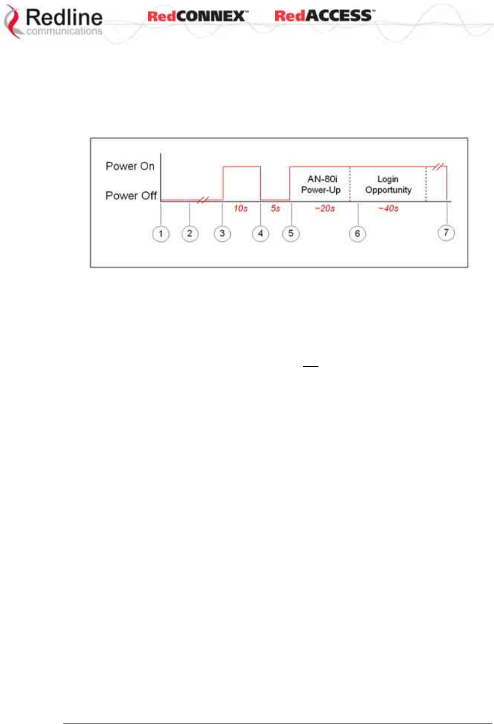
& User
AN-80i
Manual
70-00072-01-07 Proprietary Redline Communications © 2008 Page 85 of 106 Sept 18, 2008
6.2 Procedure to Restore Factory Settings
The AN-80i features a method to gain access to the CLI command prompt for a unit
where the IP address, username, and/or password is unknown. This method requires
local access to the AN-80i PoE power adapter, the ability to power-cycle the AN-80i, a
PC with a telnet client, and an Ethernet cable.
Figure 38: CLI - Recovering Lost IP Address
Use the following steps to gain access to the CLI command prompt:
1. Power-off the AN-80i PoE adapter. Remove the local network Ethernet cable and
connect your computer directly to the PoE adapter DATA (INPUT) Ethernet port.
2. Open a command prompt window on the PC and enter the command:
telnet 192.168.25.2 <Do not press Enter key at this time>
3. Restore power to the AN-80i PoE adapter and wait for 10 seconds.
4. Power-off the AN-80i PoE adapter for 5 seconds (7 seconds maximum).
5. Restore power to the AN-80i PoE adapter and wait for approximately 20 seconds.
6. Press the Enter key on the PC (start the Telnet session). When the login prompt
appears, you have approximately 30 seconds to login using 'admin' as the user
name and 'admin' as password. After login, all AN-80i CLI commands are available.
If the login prompt does not appear, re-enter the Telnet command (up to 60 seconds
from power-on). If this is not successful, repeat steps 2 to 6 using a wait time in step
5 (30 to 40 seconds).
7. Use the following command to restore the default IP address, username and
password:
save defaultconfig <Enter>
The following parameters are not affected by the 'save defaultconfig' command:
- System Name, System Location, System Details and Contact
- Frequency list
- SNMP configuration
- ID table (PMP only)
8. Power-off the PoE adapter and re-connect the network cable. Restore power to the
PoE adapter.
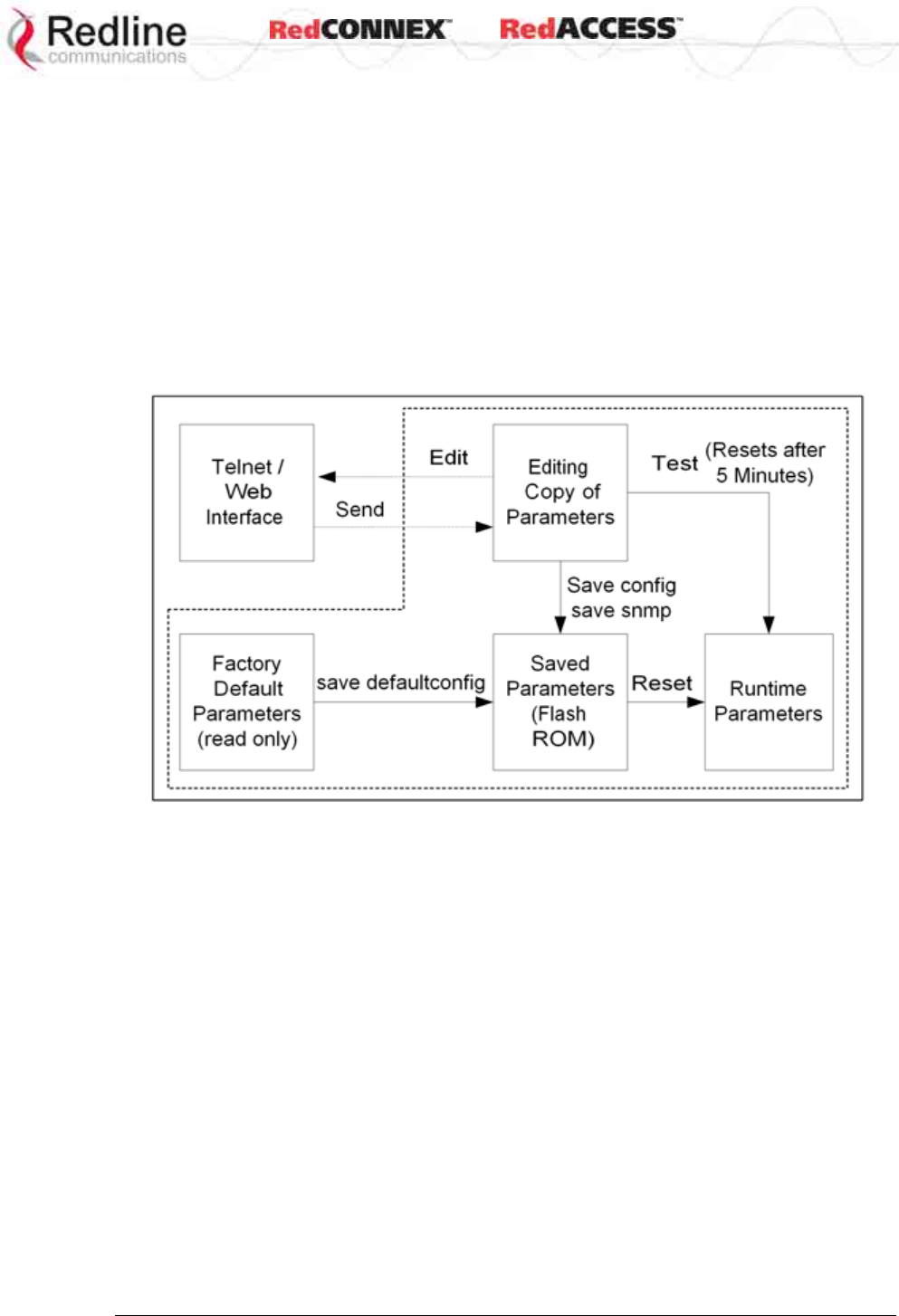
& User
AN-80i
Manual
70-00072-01-07 Proprietary Redline Communications © 2008 Page 86 of 106 Sept 18, 2008
6.3 Testing and Saving System Parameters
The AN-80i is a highly configurable communications device. All user settings are saved
in non-volatile RAM. The system configuration and snmp settings are saved separately.
6.3.1 CLI Interface
Use the 'test' command to have the AN-80i load the edited settings. The AN-80i will
operate with these settings for a period of five minutes. During the test period, you may
click the Save button at any time to save this configuration permanently. Otherwise, after
five minutes, the AN-80i will reboot and load the previously saved settings.
Note: Factory defaults can only be restored using the CLI commands.
Figure 39: Diag: - Saving Parameters in NVRAM
6.3.2 Web Interface
The Test button is located on the System Configuration page. Click this button to have
the AN-80i load the current settings displayed in the configuration screen. The AN-80i
will operate with these settings for a period of five minutes. During the test period you
may click the Save button at any time to save this configuration permanently (also
terminating the five minute timer). After five minutes, if the Save function button has not
been applied, the AN-80i will reboot and load the previously saved settings.
Attempt to login to the AN-80i using a Web browser. Microsoft Internet Explorer is
recommended. If the AN-80i does not respond by displaying the login dialog box, check
that the correct IP address is being used. The value 192.168.25.2 is the factory default
value and may have been changed during installation.
Test is to verify the IP address is reachable from the computer. Use the ping command
to test the Connection between the AN-80i and host computer.
>ping 192.168.25.2
If the ping test is successful, the host computer was able to send and receive packets
to/from the AN-80i. The problem may be with the Internet browser or related settings on
the host computer. Reboot the host computer to try to resolve the problem.

& User
AN-80i
Manual
70-00072-01-07 Proprietary Redline Communications © 2008 Page 87 of 106 Sept 18, 2008
If the ping is unsuccessful, there may be problems using that IP address; the IP address
may be incorrect, or there may be a duplicate address. For correct operation the host
computer and the AN-80i must be on the same subnet. For example, if the AN-80i is
using the factory default settings, the host computer could be set for an IP of
192.168.25.3 and a subnet mask of 255.255.255.0.
If the correct IP address of the AN-80i cannot be determined, it is recommended to
perform the IP recovery procedure. See section 6.2: Procedure to Restore Factory
Settings on page 85.
The following table lists some common troubleshooting tips for the web interface.
Table 45: Diag. - Web Interface Diagnostics
Symptom Possible Problem Solution
Incorrect IP
address and/or
Subnet Mask.
Perform a ping test from the host computer command
line.
If the ping test is unsuccessful, then the problem is
with the IP address. Perform a long reset to apply the
default address (192.168.25.2) and Subnet Mask
(255.255.255.0)
Problems with host
computer, or AN-
80i.
If the ping is successful, reset the AN-80i, and/or reset
the host computer.
General
Information
screen is not
displayed
Host PC ARP table
is incorrectly
configured
Run 'arp -d' whenever the AN-80i is swapped. Check
that the subnet mask for the host PC matches the
subnet mask of the AN-80i. Check that the host PC's
address is 192.168.25.n, where 'n' is not equal to 0,2,
or 255.
& User
AN-80i
Manual
70-00072-01-07 Proprietary Redline Communications © 2008 Page 88 of 106 Sept 18, 2008
6.4 Status Codes
6.4.1 PTP Status Codes
The PTP status code is displayed in a series of decimal characters representing the
status of six different alarm conditions. The value '1' indicates the associated condition is
active. All unused bits are set to zero.
To determine the status, the decimal number must be converted to binary notation. It is
recommended to use a scientific calculator that supports binary notation (i.e., Windows
on-screen calculator). Set the mode for decimal and enter the status code. Change the
mode to binary and match active bits (1) to the following table.
For example, if 'RF High Temp. Warning' (2) and ' PHY lock error' (1 0000) were active,
the status code value would be 34 (binary 100010) (leading zeros are not displayed).
Table 46: Diag. - PTP Status Codes
Error Type Error #
Decimal* Error #
(binary)
Description
Tx Power
1 1 Power output is less than 10 dBm. This message
may appear before the RF link is established.
RF High
Temp.
Warning
2 10 The transceiver internal temperature rose above
185F / 85C. The transceiver will shut down for 30
seconds to allow cooling.
RF PLL Lock
Error
16 1 0000 The PLL (Phase Locked Loop) section within the
AN-80i experienced an error. Reset the AN-80i.
PHY lock
error
32 10 0000 The PLL (Phase Locked Loop) section within the
AN-80i experienced an error. Reset the AN-80i.
80 MHz PLL
lock error
64 100 0000 The PLL (Phase Locked Loop) section within the
AN-80i experienced an error. Reset the AN-80i.
Firmware
Configuration
Error
128 1000 0000 Error detected in the AN-80i configuration file.
*Displayed decimal value if this is the only active error condition.
& User
AN-80i
Manual
70-00072-01-07 Proprietary Redline Communications © 2008 Page 89 of 106 Sept 18, 2008
6.4.2 PMP Status Codes
The PMP status code is displayed in a series of hexadecimal characters representing
the status of different alarm conditions. The value '1' indicates the associated condition
is active. All unused bits are set to zero.
To determine the status, the hexadecimal number must be converted to binary notation.
It is recommended to use a scientific calculator that supports binary notation (i.e.,
Windows on-screen calculator). Set the mode for Hex and enter the status code.
Change the mode to binary and match active bits (1) to the PMP Status Codes table.
For example, if 'Radio Over Temperature' bit 1 and 'PLL Error' bit 4 were active, the
status code value would be Hex '12' (binary 1 0010).
Table 47: Diag. - PMP Status Code Bits
31 30 29 28 27 26 25 24 23 22 21 20 19 18 17 16 15 14 13 12 11 9 8 7 6 5 4 3 2 1 0
Table 48: Diag. - PMP Status Codes
Bit Description
1 Radio over-temperature
4, 5, 6 PLL Errors
8 Firmware Error
16 No Ethernet packets received by the wireless MAC
17, 18, 19, 20,
21, 22, 23, 24,
25, 26, 27, 28
MAC Internal Errors

& User
AN-80i
Manual
70-00072-01-07 Proprietary Redline Communications © 2008 Page 90 of 106 Sept 18, 2008
Chapter
7
7
7
A
Ap
pp
pe
en
nd
di
ic
ce
es
s
7.1 AN-80i Technical Specifications
Table 49: Spec. - AN-80i Technical Specifications
T35 Radio:
RF Band: 3.320 - 3.798 GHz (TDD) 1
Rx Sensitivity: -95 dBm @ 3 Mbps max.
Center Freq. Steps: 1 MHz 2
Channel Size: PTP: 5, 7, 10, 14, 20, 28 MHz (software selectable) 1
PMP: 10, 20 MHz (software selectable) 1
T49 Radio:
RF Band: 4.900 - 5.350 GHz (TDD) 1
Rx Sensitivity: -88 dBm @ 3 Mbps max.
Center Freq. Steps: 2.5 MHz 2
Channel Size: PTP: 10, 20, 40 MHz (software selectable) 1
PMP: 10, 20 MHz (software selectable) 1
T54 Radio:
RF Band: 5.470 - 5.725 GHz (TDD) 1
Rx Sensitivity: -85 dBm @ 3 Mbps max.
Center Freq. Steps: 2.5 MHz 2
Channel Size: PTP: 10, 20, 40 MHz (software selectable) 1
PMP: 10, 20 MHz (software selectable) 1
T58 Radio:
RF Band: 5.725 - 5.850 GHz (TDD) 1
Rx Sensitivity: -85 dBm @ 3 Mbps max.
Center Freq. Steps: 2.5 MHz 2
Channel Size: PTP: 10, 20, 40 MHz (software selectable) 1
PMP: 10, 20 MHz (software selectable) 1
System Capability: LOS, Optical-LOS, and Non-LOS
RF: > 50 dB Rx Dynamic Range
Maximum Tx Power: 25 dBm (Ave. Max.) 3,8
Minimum Tx Power: -10 dBm
Automatic Transmit Power Control (ATPC)
Dynamic Frequency Selection (DFS)
Automatic link distance ranging
Up to 80 km (50 mi) line-of-sight @ 48 dBm EIRP 3
Data Rate: Up to 90 Mbps average Ethernet rate (40 MHz channel) 4
Rx Sensitivity: -88 dBm @ 3 Mbps max.
PoE Cable: Up to 91 m (300 ft) 5
Network Attributes: 802.3x Ethernet flow control

& User
AN-80i
Manual
70-00072-01-07 Proprietary Redline Communications © 2008 Page 91 of 106 Sept 18, 2008
Table 49: Spec. - AN-80i Technical Specifications
DHCP pass-through, transparent bridge
802.1p network traffic prioritization 6
802.1Q VLAN classification 7
Modulation/Coding Rates: BPSK 1/2, BPSK 3/4, QPSK 1/2, QPSK 3/4, 16 QAM 1/2, 16
QAM 3/4, 64 QAM 2/3 and 64 QAM 3/4
Over The Air Encryption: Proprietary private key encryption, X.509 certificates
AES-128 and AES-256 options 6
MAC: Concatenation
Time Division Multiple Access (TDMA)
Automatic Repeat Request (ARQ) error correction
Dynamic adaptive modulation (bi-dir. burst to burst auto select) 6
Packet fragmentation 7
Network Services: Transparent to 802.3 services and applications
Duplex Technique: Dynamic TDD (time division duplex)
Wireless Transmission: OFDM (orthogonal frequency division multiplexing)
Network Connection: 10/100 Ethernet (RJ-45)
System Configuration: HTTP/HTTPS (Web) interface, SNMP, SSH, Telnet (CLI), TFTP
Network Management: SNMP V2: standard and proprietary MIBs
Power Requirements: Standard IEEE 802.3af (15.4 W Max.)
Operating Temperature: -40 C to 60 C
Dimensions/Weight: 289 mm x 190 mm x 51.5 mm (11.38 in x 7.50 in x 2.03 in)
Humidity: 0% to 95% Non-condensing
Weight: 2 Kg (4.4 lb) without bracket or antenna
Storage Temperature: -50 C to 70 C
Compliance: Safety: IEC, EN, and UL/CSA 60950
EMC: EN 301 489-1, EN 301 489-17
5.8 GHz Radio: Industry Canada RSS 210, FCC part 15, ETSI EN
302 502
5.4 GHz Radio (w/DFS): Industry Canada RSS 210, FCC part 15,
ETSI EN 301 893
4.9 GHz Radio (w/DFS): Industry Canada RSS 210, FCC part 90,
ETSI EN 301 893
Ingress Protection: IP67
FCC part 15, ETSI EN 302 502;
FCC part 90, ETSI EN 301 893
1 Actual RF Band limited by regional regulations.
Refer to Table 63: Spec. - Regional Identification Codes on page 99 for available channels.
2 Center frequency is dependent on region.
3 Maximum operational power per channel with a given antenna is limited in accordance to maximum
allowable EIRP levels for the region.
4 Actual Ethernet data throughput is dependent on: protocols, packet size, burst rate, transmission
latency, and link distance.
5 With lightning arrestor installed.
6 PTP Only
7 PMP Only
8 Maximum power based on radio type.
Specifications are subject to change without notice.

& User
AN-80i
Manual
70-00072-01-07 Proprietary Redline Communications © 2008 Page 92 of 106 Sept 18, 2008
7.2 AN-80i PoE Power Adapter Specifications
Table 50: Spec. - AN-80i PoE Power Adaptor Specifications
PoE Power Block: CINCON Model TR60A-POE-L
Input: Auto-sensing 110/220/240 VAC 50/60 Hz
Output: 48 VDC 1.2A Max. Load
Environmental: Operating temperature: 0 to 60 C
Storage Temperature: -50 to 70 C
Operating Humidity: 5% to 95%
Dimensions: 35 x 70 x 150 mm (1.38 x 2.76 x 5.91 in)
Specifications are subject to change without notice.
7.3 Antenna / Mounting Bracket Matrix
Table 51: Spec. - AN-80i Antenna / Mounting Bracket Matrix
Redline Order Gain Type Freq. (GHz) Mounting
(Part) Number (dBi) 3.3 -
3.8
4.9 -
5.0
5.15 -
5.35
5.25 -
5.35
5.4 5.8 Bracket
A12015EAS
(48-00065-00) 15 120°
panel
80i-HD-MNT
(13-00043-00)
A1815MTF
(48-00012-00)
18 15°
panel
80i-HD-MNT
(13-00043-00)
A2014ARF
(48-00054-00)
20 13.8°
panel
80i-HD-MNT
(13-00043-00)
A2209MTFD
(48-00021-02) 22 9°
panel
80i-LW-MNT
(13-00052)
80i-HD-MNT
(13-00043-00)
A2212RWP
(48-00030-00) 22 12°
parabolic
80i-SA-MNT
(13-00052)
A2408MTF
(48-00009-00)
24 8°
panel
80i-HD-MNT
(13-00043-00)
A2510PWP
(48-00056-00)
25 10°
panel
80i-HD-MNT
(13-00043-00)
A2804MTF
(48-00024-00) 28 4.5°
panel
80i-HD-MNT
(13-00043-00)
A2808PWP 28 8°
panel
A2906PWP
(48-00063-00) 29 6°
parabolic
80i-SA-MNT
(13-00052)
A3204PWP
(48-00064-00) 32 4°
parabolic
80i-SA-MNT
(13-00052)
A3403RWP
(48-00033-00) 34.6 3.4°
parabolic
80i-SA-MNT
(13-00052)
A36009MMO
(48-00048-01) 9 360°
omni
80i-SA-MNT
(13-00052)

& User
AN-80i
Manual
70-00072-01-07 Proprietary Redline Communications © 2008 Page 93 of 106 Sept 18, 2008
Table 51: Spec. - AN-80i Antenna / Mounting Bracket Matrix
Redline Order Gain Type Freq. (GHz) Mounting
(Part) Number (dBi) 3.3 -
3.8
4.9 -
5.0
5.15 -
5.35
5.25 -
5.35
5.4 5.8 Bracket
A6017EAS
(48-00067-00) 17.5 62°
panel
80i-HD-MNT
(13-00043-00)
A9016EAS
(48-00066-00) 16.6 90°
panel
80i-HD-MNT
(13-00043-00)
PA14120EAS
(48-00059-00)
14 120°
panel
80i-HD-MNT
(13-00043-00)
PA14120EASH
(48-00060-00)
14 120°
panel
80i-HD-MNT
(13-00043-00)
PA1590EAS
(48-00052-00)
15 90°
panel
80i-HD-MNT
(13-00043-00)
PA1590EASH
(48-00053-00)
15 90°
panel
80i-HD-MNT
(13-00043-00)
PA1660EASH
(48-00051-00)
16 60°
panel
80i-HD-MNT
(13-00043-00)
PA1760EAS
(48-00050-00)
17 60°
panel
80i-HD-MNT
(13-00043-00)
7.4 Legacy Products (Not Available to Order)
Table 52: Spec. - AN-80i Legacy Antenna / Mounting Bracket Matrix
Redline Order Gain Type Freq. (GHz) Mounting
(Part) Number (dBi) 3.3 -
3.8
4.90 -
5.00
5.15 -
5.35
5.25 -
5.35
5.4 5.8 Bracket
A12015MTS
(48-00047-00) 15 120°
panel
80i-HD-MNT
A2806RWP
(48-00031-00) 28 6.2°
parabolic
80i-SA-MNT
A3104RWP
(48-00032-00) 31.2 4.2°
parabolic
80i-SA-MNT
A6015MTS
(48-00014-00) 16 60°
panel
80i-HD-MNT
A6017RWS
(48-00028-00) 17 60°
panel
80i-HD-MNT
A9014MTS
(48-00017-00) 14 90°
panel
80i-HD-MNT
A9016RWS
(48-00029-00) 16 90°
panel
80i-HD-MNT
& User
AN-80i
Manual
70-00072-01-07 Proprietary Redline Communications © 2008 Page 94 of 106 Sept 18, 2008
7.5 ETSI Certified Antennas
The RF output power and selection must be professionally programmed and installed by
the manufacturer or a trained professional installer.
7.5.1 3.3 - 3.8 GHz Radio: ETSI Certified Antennas
The following table lists ETSI certified 3.3 - 3.8 GHz antennas. Operation is restricted to
10 MHz and 20 MHz channel operation only.
Table 53: Spec. - Antenna/Tx Power Setting Combinations for ETSI
Redline Part
Number
Gain
(dBi)
Description
A2014ARF
(48-00054-00)
20 13.8°, 3.3-3.8 GHz, horizontal or vertical polarization
A2408MTF
(48-00009-00)
24 8°, 3.3-3.8 GHz, horizontal or vertical polarization
A1815MTF
(48-00012-00)
18 15°, 3.3-3.8 GHz, horizontal or vertical polarization
A2510PWP
(48-00056-00)
25 10°, 3.3-3.6 GHz, horizontal or vertical polarization
A2808PWP 28 8°, 3.3-3.8 GHz, horizontal or vertical polarization
PA1760EAS
(48-00050-00)
17 60°, 3.3-3.8 GHz, vertical polarization only
PA1660EASH
(48-00051-00)
16 60°, 3.3-3.8 GHz, horizontal polarization only
PA1590EAS
(48-00052-00)
15 90°, 3.3-3.8 GHz, vertical polarization only
PA1590EASH
(48-00053-00)
15 90°, 3.3-3.8 GHz, horizontal polarization only
PA14120EAS
(48-00059-00)
14 120°, 3.3-3.8 GHz, vertical polarization only
PA14120EASH
(48-00060-00)
14 120°, 3.3-3.8 GHz, horizontal polarization only
7.5.2 5.8 GHz Radio: ETSI Certified Antennas
The following table lists ETSI certified 5.8 GHz antennas. Operation is restricted to 10
MHz and 20 MHz channel operation only.
Table 54: Spec. - ETSI Certified Antennas: 5.8 GHz Operation
Redline Part
Number
Gain
(dBi)
Antenna Type App. Tx Power
Setting (dBm)
A36009MMO
(48-00048-01)
9 360°, 5.0 - 6.0 GHz, omni directional PMP 13
A12015EAS
(48-00065-00)
15 120°, 4.9-5.9 GHz, sector flat panel PMP 9
A9016EAS
(48-00066-00)
16.6 90°, 4.9-5.9 GHz, sector flat panel PMP 7
A6017EAS
(48-00067-00)
17.5 62°, 4.9-5.9 GHz, sector flat panel PMP 5
A2209MTFD
(48-00021-02)
22 9°, 5.15-5.875 GHz, flat panel PTP -1
A2212RWP
(48-00030-00)
22 12°, 5.250-5.850 GHz, parabolic PTP -1
& User
AN-80i
Manual
70-00072-01-07 Proprietary Redline Communications © 2008 Page 95 of 106 Sept 18, 2008
7.5.3 5.4 GHz Radio: ETSI Certified Antennas
The following table lists ETSI certified 5.4 GHz antennas.
Table 55: Spec. - ETSI Certified Antennas: 5.4 GHz Operation
Redline Part
Number
Gain
(dBi)
Antenna Type App. Tx Power
Setting (dBm)
A36009MMO
(48-00048-01)
9 360°, 5.0 - 6.0 GHz, omni PMP 10
A12015EAS
(48-00065-00)
15 120°, 4.9-5.9 GHz, sector flat panel PMP 5
A9016EAS
(48-00066-00)
16.6 90°, 4.9-5.9 GHz, sector flat panel PMP 3
A6017EAS
(48-00067-00)
17.5 62°, 4.9-5.9 GHz, sector flat panel PMP 2
A2209MTFD
(48-00021-02)
22 9°, 5.15-5.875 GHz, flat panel PTP 8
A2212RWP
(48-00030-00)
22 12°, 5.250-5.850 GHz, parabolic PTP 8
A2804MTF
(48-00024-00)
28 4.5°, 5.15-5.875 GHz, flat panel PTP 1
A2806RWP
(48-00031-00)
28 6.2°, 5.250-5.850 GHz, parabolic PTP 1
A2906PWP
(48-00063-00)
29 6°, 4.900-5.875 GHz, parabolic PTP 10
A3104RWP
(48-00032-00)
31.2 4.2°, 5.250-5.850 GHz, parabolic PTP -1
A3204PWP
(48-00064-00)
32 4°, 4.900-5.875 GHz, 3 ft, parabolic PTP -3
7.5.4 5.15 - 5.35 GHz Radio: ETSI Antennas
The following table lists ETSI certified 5.15-5.35 GHz antennas.
Table 56: Spec. - ETSI Certified Antennas: 5.15 - 5.35 GHz Operation
Redline Order
(Part) Number
Gain
(dBi)
Antenna Type App. Tx Power
Setting (dBm)
A12015EAS
(48-00065-00)
15 120°, 4.9-5.9 GHz, sector flat panel PMP 3
A9016EAS
(48-00066-00)
16.6 90°, 4.9-5.9 GHz, sector flat panel PMP 2
A6017EAS
(48-00067-00)
17.5 62°, 4.9-5.9 GHz, sector flat panel PMP 0
A2209MTFD
(48-00021-02)
22 9°, 5.15-5.875 GHz, flat panel PTP -4
& User
AN-80i
Manual
70-00072-01-07 Proprietary Redline Communications © 2008 Page 96 of 106 Sept 18, 2008
7.6 FCC & IC Certified Antennas
7.6.1 5.8 GHz Radio: FCC & IC Certified Antennas
This device has been designed to operate with the antennas listed below, and having a
maximum gain of 34.6 dBi. Antennas having a gain greater than 34.6 dBi are strictly
prohibited for use with this device. The RF output power and selection must be
professionally programmed and installed by the manufacturer or a trained professional
installer. The required antenna impedance is 50 ohms. The following tables list FCC and
IC certified antennas.
Table 57: Spec. - FCC & IC Certified Antennas: 5.8 GHz PTP Operation
Redline Order
(Part) Number
Gain
(dBi)
Description App. Ave. GUI
Power
Display
(dBm)
Minimum
Conducted
Power
(dBm)
Max
Conducted
Power
(dBm)
A2209MTFD
(48-00021-02)
22 9°, 5.15-5.875 GHz, flat panel PTP 20 -12.7 26.2
A2212RWP
(48-00030-00)
22 12°, 5.250-5.850 GHz, parabolic PTP 20 -12.7 26.2
A2804MTF
(48-00024-00)
28 4.5°, 5.15-5.875 GHz, flat panel PTP 20 -12.7 26.2
A2806RWP
(48-00031-00)
28 6.2°, 5.250-5.850 GHz, parabolic PTP 20 -12.7 26.2
A2906PWP
(48-00063-00)
29 6°, 4.900-5.875 GHz, parabolic PTP 20 -12.7 26.2
A3104RWP
(48-00032-00)
31.2 4.2°, 5.250-5.850 GHz, parabolic PTP 20 -12.7 26.2
A3204PWP
(48-00064-00)
32 4°, 4.900-5.875 GHz, parabolic PTP 20 -12.7 26.2
A3403RWP
(48-00033-00)
34.6 3.4°, 5.250-5.850 GHz, parabolic PTP 20 -12.7 26.2
Table 58: Spec. - FCC & IC Certified Antennas: 5.8 GHz PMP Operation
Redline Part
Number
Gain
(dBi)
Description App. Tx Power
Setting
(dBm)
Tx Peak
Conducted
Power
(dBm)
A36009MMO
(48-00048-01)
9 360°, 5.0 - 6.0 GHz, omni directional PMP 13 20.3
A12015EAS
(48-00065-00)
15 120°, 4.9-5.9 GHz, sector flat panel PMP 9 19.4
A9016EAS
(48-00066-00)
16.6 90°, 4.9-5.9 GHz, sector flat panel PMP 7 17.2
A6017EAS
(48-00067-00)
17.5 62°, 4.9-5.9 GHz, sector flat panel PMP 5 14.9
A9014MTS
(48-00017-00)
14 90°, 5.150-5.875 GHz, sector flat panel PMP 10 20.5
A12015MTS
(48-00047-00)
15 120°, 5.15-5.875 GHz, sector, flat
panel
PMP 9 19.4
A6015MTS
(48-00014-00)
16 60°, 5.150-5.875 GHz, sector flat panel PMP 8 18.3
A9016RWS
(48-00029-00)
16 90°, 5.250-5.850 GHz, sector, flat
panel
PMP 8 18.3
A6017RWS
(48-00028-00)
17 60°, 5.250-5.850 GHz, sector, flat
panel
PMP 7 17.1
& User
AN-80i
Manual
70-00072-01-07 Proprietary Redline Communications © 2008 Page 97 of 106 Sept 18, 2008
7.6.2 5.4 GHz Radio: FCC & IC Certified Antennas
This device has been designed to operate with the antennas listed below, and having a
maximum gain of 22 dBi. Antennas not included in this list or having a gain greater than
22 dBi are strictly prohibited for use with this device. The required antenna impedance is
50 ohms. The following table lists FCC and IC certified antennas:
Table 59: Spec. - FCC & IC Certified Antennas: 5.4 GHz Operation
Redline Order
(Part) Number
Gain
(dBi)
Description App. Tx Power
Setting (dBm)
A36009MMO
(48-00048-01)
9 360°, 5.0 - 6.0 GHz, omni directional PMP 13
A12015EAS
(48-00065-00)
15 120°, 4.9-5.9 GHz, sector flat panel PMP 9
A9016EAS
(48-00066-00)
16.6 90°, 4.9-5.9 GHz, sector flat panel PMP 7
A6017EAS
(48-00067-00)
17.5 62°, 4.9-5.9 GHz, sector flat panel PMP 5
A2209MTFD
(48-00021-02)
22 9°, 5.15-5.875 GHz, sector, flat panel PTP -1
7.6.3 5.25 - 5.35 GHz Radio: FCC & IC Antennas
This device has been designed to operate with the antennas listed below, and having a
maximum gain of 22 dBi. Antennas not included in this list or having a gain greater than
22 dBi are strictly prohibited for use with this device. The required antenna impedance is
50 ohms. The RF output power and selection must be professionally programmed and
installed by the manufacturer or a trained professional installer. The following table lists
FCC* and IC certified antennas:
Table 60: Spec. - FCC & IC Antennas: 5.25 - 5.35 GHz Operation
Tx Power Setting
(dBm)
Tx Peak Conducted
Power (dBm)
Channel Size (MHz) Channel Size (MHz)
Redline Order
(Part) Number
Gain
(dBi)
Description App.
10 20 40 10 20 40
A36009MMO
(48-00048-01)
9 360°, 5.0 - 6.0 GHz,
omni directional
PMP 12 14 N/A 20 21 N/A
A12015EAS
(48-00065-00)
15 120 deg., .9-5.9 GHz,
sector flat panel
PMP 6 8 N/A 21 22 N/A
A9016EAS
(48-00066-00)
16.6 90 deg., 4.9-5.9 GHz,
sector flat panel
PMP 5 7 N/A 21 22 N/A
A6017EAS
(48-00067-00)
17.5 62 deg., 4.9-5.9 GHz,
sector flat panel
PMP 4 6 N/A 20 22 N/A
A2209MTFD
(48-00021-02)
22 9°, 5.15-5.875 GHz,
sector, flat panel
PTP -4 -2 -1 17 19 20
* FCC regulations require the DFS function be permanently enabled at the factory
and can not be disabled by the installer/end-user when operating in the 5.25-5.35
GHz range.
7.6.4 4.94 - 4.99 GHz Radio: FCC & IC Antennas
This device has been designed to operate with the antennas listed below, and having a
maximum gain of 32 dBi. Antennas not included in this list or having a gain greater than
32 dBi are strictly prohibited for use with this device. The required antenna impedance is
50 ohms. The RF output power and selection must be professionally programmed and
installed by the manufacturer or a trained professional installer. The following table lists
FCC and IC certified antennas:
& User
AN-80i
Manual
70-00072-01-07 Proprietary Redline Communications © 2008 Page 98 of 106 Sept 18, 2008
Table 61: Spec. - FCC & IC Antennas: 4.94 - 4.99 GHz Operation
GUI Settings (dBm) Tx Peak Conducted
Power (dBm)
Channel Size (MHz) Channel Size (MHz)
Redline Order
(Part) Number Gain
(dBi)
Description App.
10 20 40* 10 20 40*
A12015EAS
(48-00065-00)
15 120 deg., .9-5.9 GHz,
sector flat panel
PMP 18 20 N/A 42 43 N/A
A9016EAS
(48-00066-00)
16.6 90 deg., 4.9-5.9 GHz,
sector flat panel
PMP 18 20 N/A 43 44 N/A
A6017EAS
(48-00067-00)
17.5 62 deg., 4.9-5.9 GHz,
sector flat panel
PMP 18 20 N/A 44 45 N/A
A2906PWP
(48-00063-00)
29 6 deg., 4.900-5.875 GHz,
2 ft parabolic
PMP 15 19 N/A 53 57 N/A
A3204PWP
(48-00064-00)
32 4 deg., 4.900-5.875 GHz,
3 ft parabolic
PMP
13 16 19 54 58 60
* Industry Canada (IC) only -- FCC regulations do not allow use of 40 MHz
channels.
7.6.5 3.650 - 3.675 GHz Radio: FCC & IC Antennas
This device has been designed to operate with the antennas listed below, and having a
maximum gain of 32 dBi. Antennas not included in this list or having a gain greater than
32 dBi are strictly prohibited for use with this device. The required antenna impedance is
50 ohms. The RF output power and selection must be professionally programmed and
installed by the manufacturer or a trained professional installer. The following table lists
FCC and IC certified antennas:
Table 62: Spec. - Antenna/Tx Power Setting Combinations for FCC
GUI Setting for Channel (dBm) Redline Order
(Part) Number
Gain
(dBi)
Description
3.5
MHz
5
MHz
7
MHz
10
MHz
14
MHz
20
MHz
28
MHz
A2014ARF
(48-00054-00)
20 13.8 deg., 3.3-3.8 GHz
horizontal or vertical
polarization
15 17 18 20 21 23 24
A2408MTF
(48-00009-00)
24 8 deg., 3.3-3.8 GHz
horizontal or vertical
polarization
11 13 14 16 17 19 20
A1815MTF
(48-00012-00)
18 15 deg., 3.3-3.8 GHz
horizontal or vertical
polarization
17 19 20 22 23 25 25
A2510PWP
(48-00056-00)
25 10 deg., 3.3-3.6 GHz
horizontal or vertical
polarization
10 12 13 15 16 18 19
A2808PWP 28 8 deg., 3.3-3.8 GHz
horizontal or vertical
polarization
7 9 10 12 13 15 16
PA1760EAS
(48-00050-00)
17 60 deg., 3.3-3.8 GHz
vertical polarization
only
18 20 21 23 24 25 25
PA1660EASH
(48-00051-00)
16 60 deg., 3.3-3.8 GHz
horizontal polarization
only
19 21 22 24 25 25 25
PA1590EAS
(48-00052-00)
15 90 deg., 3.3-3.8 GHz
vertical polarization
only
20 22 23 25 25 25 25
& User
AN-80i
Manual
70-00072-01-07 Proprietary Redline Communications © 2008 Page 99 of 106 Sept 18, 2008
Table 62: Spec. - Antenna/Tx Power Setting Combinations for FCC
GUI Setting for Channel (dBm) Redline Order
(Part) Number
Gain
(dBi)
Description
3.5
MHz
5
MHz
7
MHz
10
MHz
14
MHz
20
MHz
28
MHz
PA1590EASH
(48-00053-00)
15 90 deg., 3.3-3.8 GHz
horizontal polarization
only
20 22 23 25 25 25 25
PA14120EAS
(48-00059-00)
14 120 deg., 3.3-3.8 GHz
vertical polarization
only
20 23 24 25 25 25 25
PA14120EASH
(48-00060-00)
14 120 deg., 3.3-3.8 GHz
horizontal polarization
only
20 23 24 25 25 25 25
7.7 Regional Codes
The regional code is incorporated into the options key. This feature enforces compliance
to regional regulatory statutes.
Table 63: Spec. - Regional Identification Codes
Regions Band
DFS/CBP
Required 1
Channel
Size (MHz)
Channel
Step (MHz)
Start - End 2
(MHz)
Region 01
US 5.8 ISM No 10 2.5 5730 - 5845
20 2.5 5735 - 5840
CALA, Canada,
China, Middle-
East, US 40 2.5 5745 - 5830
Region 02
UK 5.8G Yes 3
10 2.5 5730 - 5790
5820 - 5845
UK, Jersey,
Norway
20 2.5 5735 - 5785
5825 - 5840
Region 03
CE 5.4G Yes 4 10 20 5500 - 5700
20 20 5500 - 5700
EU
40 20 5500 - 5700
Region 04
US 5.4 ICM Yes 5 10 2.5 5475 - 5720
20 2.5 5480 - 5715
US
40 2.5 5490 - 5705
Region 05
IC 5.4G
Yes 6 10 2.5 5475 - 5595
5655 - 5720
20 2.5 5480 - 5590
5660 - 5715
Canada
40 2.5 5490 - 5580
5670 - 5705
Region 06
IN 5.8 G No 10 2.5 5830 - 5870
20 2.5 5735 - 5865
India
40 2.5 5845 - 5855
Region 07
DE 5.8 G Yes 8 10 2.5 5750 - 5870
20 2.5 5765 - 5865
Denmark
Region 08
US No 10 2.5 4945 - 4985 US
4940 - 4990 20 2.5 4950 - 4980
US Yes
5 10 2.5 5260 - 5340
5.250 - 5.350 20 2.5 5265 - 5335
& User
AN-80i
Manual
70-00072-01-07 Proprietary Redline Communications © 2008 Page 100 of 106 Sept 18, 2008
Table 63: Spec. - Regional Identification Codes
Regions Band
DFS/CBP
Required 1
Channel
Size (MHz)
Channel
Step (MHz)
Start - End 2
(MHz)
Region 09
IC 4.9 G No 7 10 2.5 4945 - 4985
20 2.5 4950 - 4980
Canada
40 2.5 4960 - 4970
IC 5.3 G No 6 10 2.5 5260 - 5340
20 2.5 5265 - 5335
40 2.5 5280 - 5320
Region 10
JP 4.9 G No 10 2.5 4905 - 5085 Japan
20 2.5 4910 - 5080
Region 11
CE .2 G No 10 2.5 5155 - 5245
5.155 - 5.245 20 2.5 5160 - 5240
EU
40 2.5 5170 - 5230
CE Yes
4 10 2.5 5255 - 5345
5.255 - 5.345 20 2.5 5260 - 5340
40 2.5 5270 - 5330
Region 12
US Yes
5 10 2.5 5260 - 5340 US
5.260 - 5.350 20 2.5 5265 - 5335
40 2.5 5280 - 5320
Region 13
IC 5.3 G No 6 10 2.5 5260 - 5340
20 2.5 5265 - 5335
Canada
40 2.5 5280 - 5320
Region 14
No 5 1 3302.5 - 3797.5
7 1 3303.5 - 3796.5
10 1 3305 - 3795
14 1 3307 - 3793
20 1 3310 - 3790
28 1 3314 - 3786
Region 15
US FCC 3.6 G Yes9
3.5 1 _3652 - 3673
_5 1 _3653 - 3672
_7 1 3654 - 3671
10 1 3655 - 3670
14 1 3657 - 3668
20 1 3660 - 3665
Notes:
1. Where DFS is required by regional regulations, this function is permanently enabled at the
factory and can not be disabled by the installer or end-user.
2. Center frequencies.
3. UK VNS 2107/ EN302 502
4. ETSI EN301893 v1.3.1
5. FCC Part 15
6. IC RSS-210
7. IC RSS-111
8. TKG § 55/EN302 502
9. CBP (Contention Based Protocol) as per FCC regulation CFR Part 90.1321

& User
AN-80i
Manual
70-00072-01-07 Proprietary Redline Communications © 2008 Page 101 of 106 Sept 18, 2008
7.8 Security Keys and Certificates
The certificates and keys required by the cryptographic modules are saved in non-
volatile memory. The certificates and keys are checked and loaded at each reboot. User
(usr) settings take precedence over factory (factory) settings. The following table lists the
methods for using CLI to configure operation with SSH or SSL.
Using SSH
When the software is first upgraded, the SSH 'usr' fields for DSA and RSA are blank.
The operator may download a customer-defined RSA and DSA key pair, or use the
'generate' command to create keys locally on the AN-80i. Note that customer-defined
key files must conform to the filename format described in Table 66: Security -- User Key
and Certificate Files. For example, the DSA key file for AN-80i with MAC address 00-09-02-00-
01-02 may be named: dsa_key_00-09-02-00-01-02.pem.
Using SSL (TLS)
When the software is first upgraded, the SSL 'usr' fields are blank. The operator may
download a customer-defined RSA and DSA key pair, or use the default (embedded)
certificate and private key (identical for all AN-80i units). Note that customer-defined
certificate and key files must conform to the filename format described in Table 66:
Security -- User Key and Certificate Files. For example, SSL certificate file for AN-80i with
MAC address 00-09-02-00-01-02 may be named: ssl_cert_00-09-02-00-01-02.pem.
Table 64: Security -- Keys and Certificates
Feature Parameters Field Upgrade Factory 3.00 Unit
(Future)
SSH:
Secure
CLI
dsa_key_<mac>.pem
rsa_key<mac>.pem.
1. Use 'generate' command to
create RSA and DSA key pair
locally on AN-80i and save in
'usr' settings.
--- or ---
2. Use 'load' command to save
customer-defined RSA and
DSA key pair in 'usr' settings.
(1) and (2) as in field
upgrade plus:
3. Factory supplied RSA
and DSA key pair may be
pre-loaded into factory
settings for out-of-box
SSH functionality.
SSL:
Secure
Web
ssl_cert<mac>.pem
ssl_key<mac>.pem
1. Use the default (embedded)
certificate and private key.
--- or ---
2. Use 'load' command to save
customer-defined certificate and
private key in 'usr' settings.
(1) and (2) as in field
upgrade.
Note: Use the 'minus' character to delimit the MAC address.
& User
AN-80i
Manual
70-00072-01-07 Proprietary Redline Communications © 2008 Page 102 of 106 Sept 18, 2008
7.9 Security Certificate and Key CLI Commands
The following table lists keys and certificates loaded into runtime settings at reboot. Use
the CLI command 'show files run' to display the runtime settings.
Table 65: Security -- Runtime Keys and Certificates
dsa_key_<mac>.pem DSA key used for SSH.
rsa_key_<mac>.pem RSA Key used for SSH.
ssl_cert<mac>.pem SSL X.509 certificate.
ssl_key<mac>.pem SSL RSA key.
fact_wacert_<mac>.der* Factory X.509 authority certificate for the wireless
cryptographic module. Can not be changed by the end-
user.
fact_wcert_<mac>.der* Factory X.509 certificate for the wireless cryptographic
module.
fact_wkey_<mac>.der* Factory RSA key for the wireless cryptographic module.
usr_wacert_<mac>.der* User X.509 authority certificate for the wireless
cryptographic module.
usr_wcert_<mac>.der* User X.509 certificate for the wireless cryptographic
module.
usr_wkey_<mac>.der* User RSA key for the wireless cryptographic module.
*Not used in v3.00 software release.
The following table lists the keys and certificates entered by the operator (administrator).
Use the CLI commands 'load' and 'del' to add and remove files. Use the CLI command
'generate' to update the DSA and RSA key files locally on the AN-80i.
Table 66: Security -- User Key and Certificate Files
dsa_key_<mac>.pem DSA key used for SSH.
rsa_key_<mac>.pem RSA Key used for SSH.
ssl_cert<mac>.pem SSL Certificate.
ssl_key<mac>.pem SSL Key.
usr_wacert_<mac>.der* User wireless authority certificate
usr_wcert_<mac>.der* User wireless certificate.
usr_wkey_<mac>.der* User wireless key.
*Not used in v3.00 software release.
Use the following CLI commands to view and modify the security certificates and keys.
show files <mode>
List the key and certificate files.
<mode> run - displays keys currently in use.
usr - displays user-specified keys and certificates (default if mode not
specified).

& User
AN-80i
Manual
70-00072-01-07 Proprietary Redline Communications © 2008 Page 103 of 106 Sept 18, 2008
generate sshkey <type>
Create keys of the specified type. The keys are saved in flash and runtime memory.
<type> Can be dsa or rsa.
load file <server> <name> <mode>
Save specified file in flash memory and runtime settings.
<server> IP address of the TFTP server. Files must be stored in the TFTP server
default download directory.
<name> File name on server. File name must be one of the following:
dsa_key_<mac>.pem DSA key used for SSH.
rsa_key_<mac>.pem RSA Key used for SSH.
ssl_cert_<mac>.pem SSL Certificate.
ssl_key_<mac>.pem SSL Key.
usr_wcert_<mac>.der User wireless certificate.
usr_wkey_<mac>.der User wireless key.
usr_wacert_<mac>.der User wireless authority certificate
The <mac> portion is the MAC address of the board.
For example: dsa_key_00-09-02-00-01-02.pem
<mode> Can be 'usr' or 'factory'. Defaults to 'usr' if mode is not specified.
del file <name> <mode>
Remove a file from flash and runtime memory.
<name> File name on server. File name must be one of the following:
dsa_key_<mac>.pem DSA key used for SSH.
rsa_key_<mac>.pem RSA Key used for SSH.
ssl_cert_<mac>.pem SSL Certificate.
ssl_key_<mac>.pem SSL Key.
usr_wcert_<mac>.der* User wireless certificate.
usr_wkey_<mac>.der* User wireless key.
usr_wacert_<mac>.der* User wireless authority certificate
The <mac> portion is the MAC address of the board.
For example: dsa_key_00-09-02-00-01-02.pem
<mode> Can be 'usr' or 'factory'. Defaults to 'usr' if mode is not specified.
*Not used in v3.00 software release.

& User
AN-80i
Manual
70-00072-01-07 Proprietary Redline Communications © 2008 Page 104 of 106 Sept 18, 2008
7.10 Glossary Of Terms
Table 67: Spec. - Glossary
Term Definition
Antenna
Gain
The measure of antenna performance relative to a theoretical antenna called an
isotropic antenna.
ARQ Automatic Repeat Request. This is the protocol used over the air for error
correction.
ATPC Automatic Transmission Power Control. The sector controller-end system
automatically adjusts the RF transmit level of both systems to optimize
performance of the link.
Beamwidth The angle of signal coverage provided by an antenna.
BFW Broadband Fixed Wireless
Bps Bits Per Second. Unit of measurement for the rate at which data is transmitted.
BPSK Binary Phase Shift Keying
Channel A communications path wide enough to permit a single RF transmission.
CIR Committed information rate
dB A ratio expressed in decibels.
dBi A ratio, measured in decibels, of the effective gain of an antenna compared to
an isotropic antenna.
dBm Decibels above a milliwatt.
DFS Dynamic Frequency Selection (DFS) can detect interference from other devices
using the same frequency (especially radar) and automatically take a pre-
selected action such as disable transmission or use alternative frequency.
DHCP Dynamic Host Configuration Protocol. A DHCP server automatically issues IP
addresses within a specified range to devices on a network.
Directional
Antenna
An antenna that concentrates transmission power into one direction.
Encryption For the purposes of privacy, the transformation of data into an unreadable
format until reformatted with a decryption key.
Ethernet A LAN architecture using a bus or star topology.
FD Full Duplex. Refers to the transmission of data in two directions simultaneously.
FWA Fixed Wireless Access
Gain The ratio of the output amplitude of a signal to the input amplitude of a signal.
Typically expressed in decibels (dB).
Gateway A network point that acts as an entrance to another network.
GHz Gigahertz. 1,000,000,000 Hz, or 1,000 MHz
GUI Graphical User Interface
IP Internet Protocol. See TCP/IP.
Isotropic A theoretic construct of an antenna that radiates its signal 360 degrees both
vertically and horizontally—a perfect sphere. Generally used as a reference.
IXC Inter-exchange Carrier. A long-distance phone company.
LEC Local Exchange Carriers. The traditional local wired phone company.
LED Light Emitting Diode
LOS Line Of Sight. A clear direct path between two antennas, with no obstructions
within the first Fresnel zone.
MAC Media Access Control. A unique number assigned to a network device.

& User
AN-80i
Manual
70-00072-01-07 Proprietary Redline Communications © 2008 Page 105 of 106 Sept 18, 2008
Table 67: Spec. - Glossary
Term Definition
Corresponds to ISO Network Model Layer 2 data link layer.
MHz Megahertz. 1,000,000 Hz
Modem MOdulator/DEModulator. A hardware device that converts digital data into
analog and vice versa.
Modulation Any of several techniques for combining user information with a transmitter
carrier signal.
Multipath The radio echoes created as a radio signal bounces off objects.
NVRAM Non-volatile RAM. System parameters are stored in NVRAM. This data is not
affected by powering off the system.
NLOS Non Line Of Sight. Completely obstructed path between two antennas.
OFDM Orthogonal Frequency Division Multiplexing. OFDM spreads data to be
transmitted over a large number of orthogonal carriers.
OLOS Optical Line Of Sight. A clear direct path between two antennas, with
obstructions within the first Fresnel zone.
Packet A bundle of data organized in a specific way for transmission. The three
principal elements of a packet include the header, the text, and the trailer (error
detection and correction bits).
PHY Physical Layer. Provides for the transmission of data through a communications
channel by defining the electrical, mechanical, and procedural specifications.
PIR Peak Information Rate
PMP Point to Multipoint
PTP Point to Point
QAM Quadrature Amplitude Modulation
QPSK Quadrature Phase Shift Keying
Receiver
Sensitivity
A measurement of the weakest signal a receiver can receive and still correctly
translate it into data.
RF Radio Frequency
RSSI Received Signal Strength Indication
Rx Receiver
S/N Signal to Noise Ratio
SINADR Signal to noise and distortion ratio.
SSL Secure Sockets Layer, a communications protocol, superceded by Transport
Layer Security (TLS).
TCP/IP Transmission Control Protocol/Internet Protocol
The standard set of protocols used by the Internet for transferring information
between computers, handsets, and other devices.
TFTP Trivial File Transfer Protocol
TLS Transport Layer Security (TLS) and its predecessor, Secure Sockets Layer
(SSL), are cryptographic protocols that provide secure communications on the
Internet for web browsing, e-mail, Internet faxing, instant messaging and other
data transfers.
Tx Transmitter
UBR Uncoded Burst Rate

70-00072-01-07 Proprietary Redline Communications © 2008 Page 106 of 106 Sept 18, 2008
302 Town Centre • Suite 100 • Markham, Ontario • Canada • L3R 0E8
www.redlinecommunications.com