Redline Communications AN80IE OFDM broadband wireless transceiver device User Manual 70 00072 01 07
Redline Communications Inc. OFDM broadband wireless transceiver device 70 00072 01 07
UserManual.wiki
>
Redline Communications
>
AN80IE User Manual
>
user manual
Contents
1.
an80i manual update
2.
user manual
user manual
Navigation menu
Upload a User Manual
Namespaces
Wiki Guide
HTML
PDF
Info
Views
User Manual
Discussion / Help
Navigation

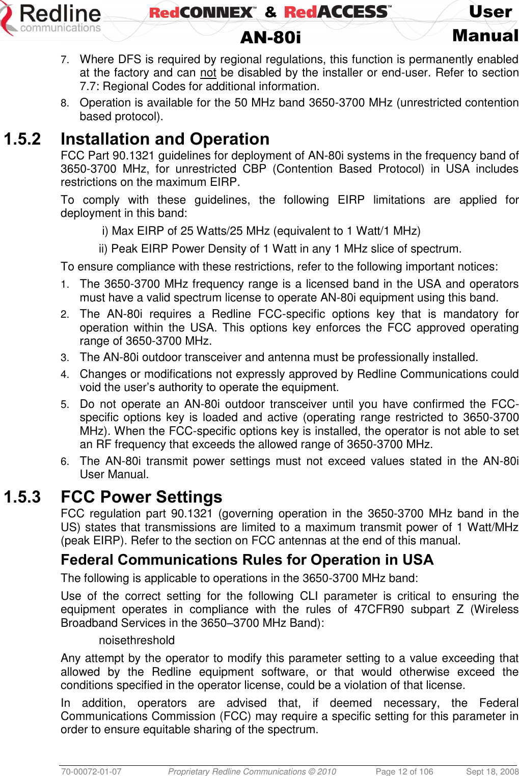
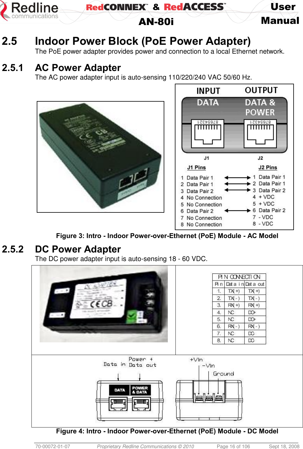
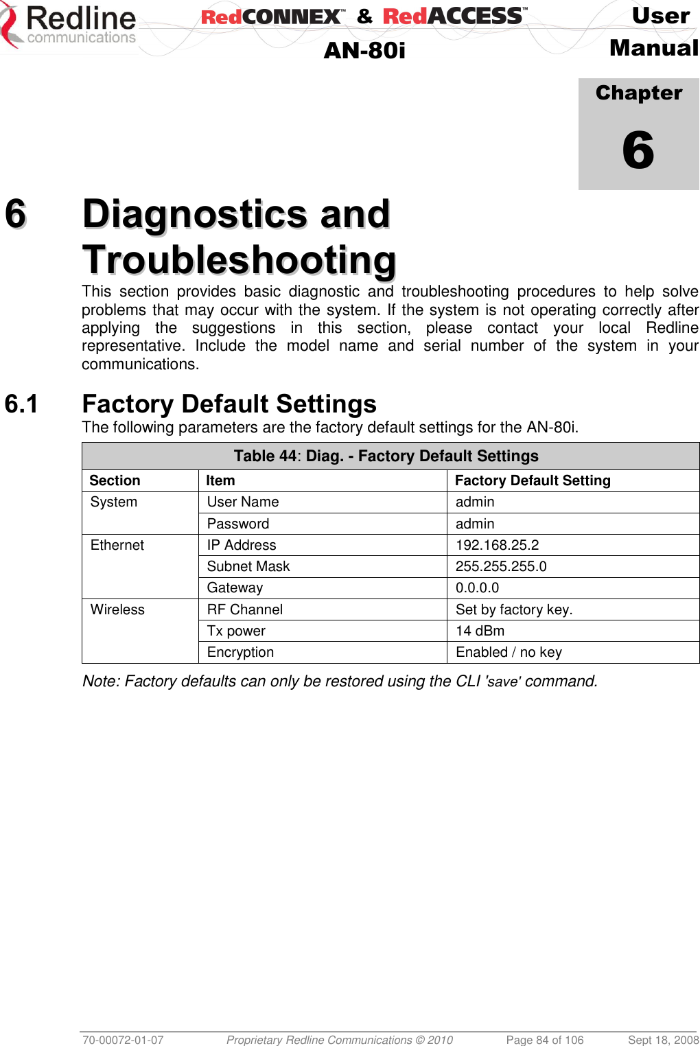
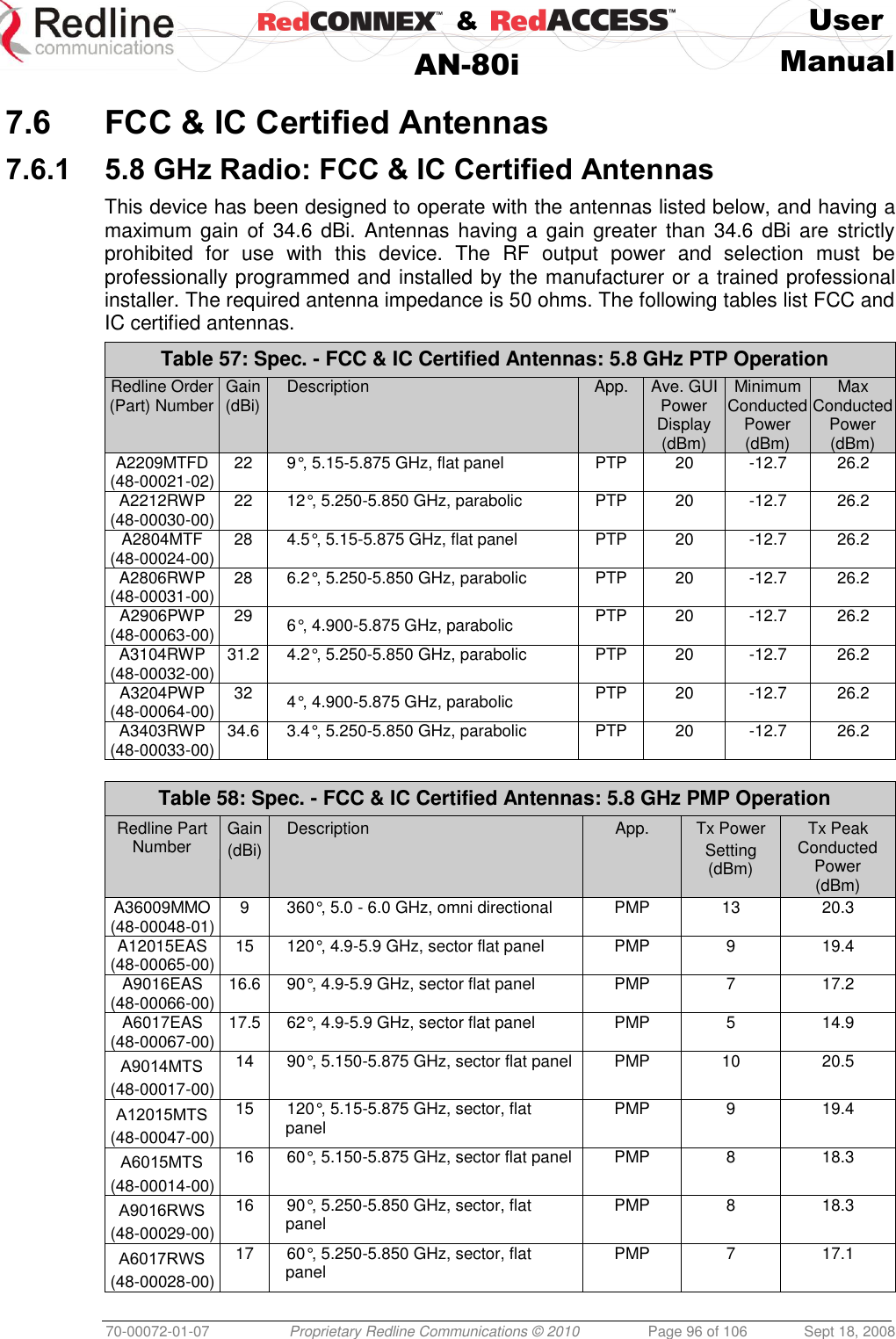
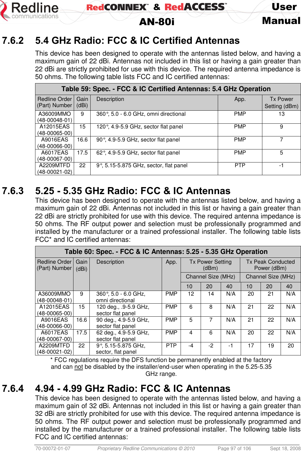
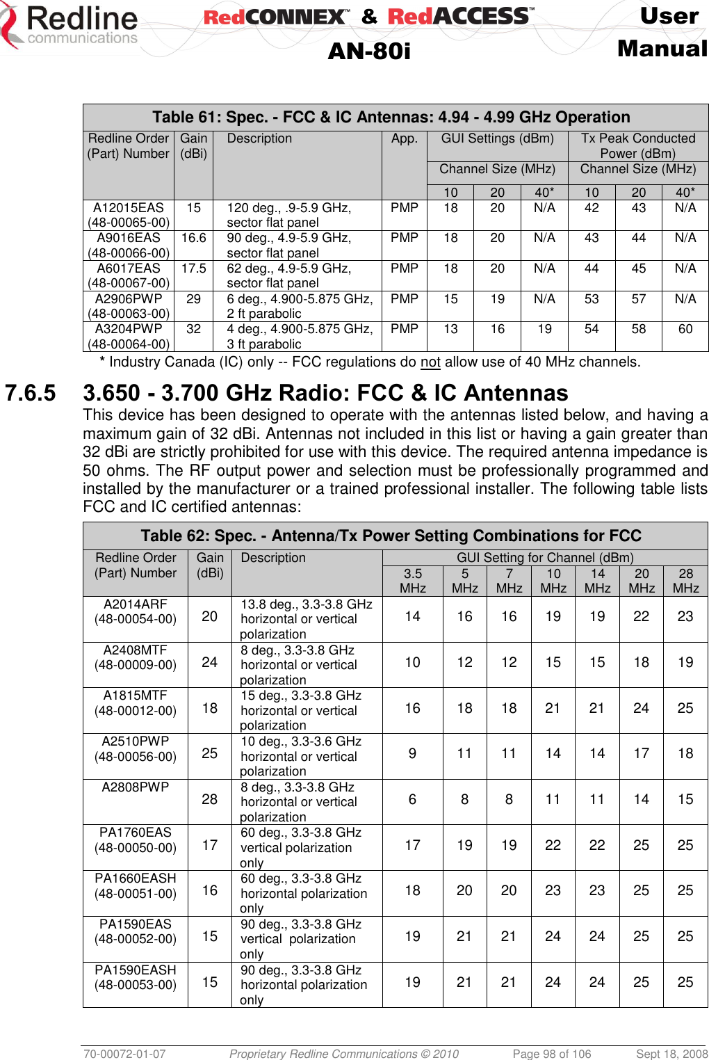
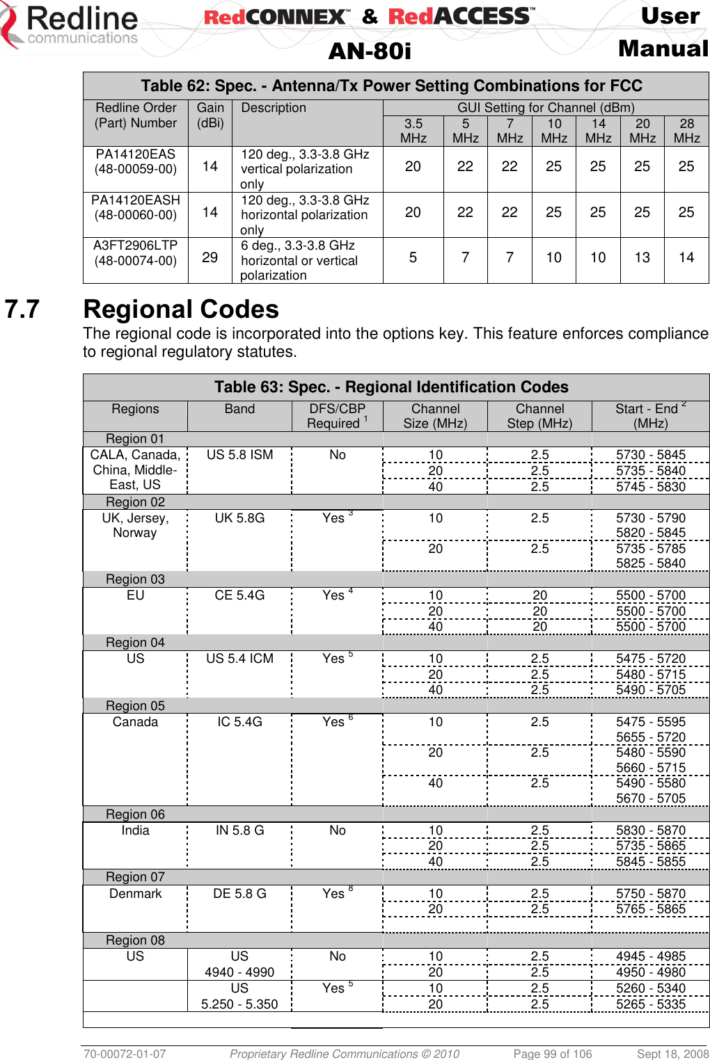
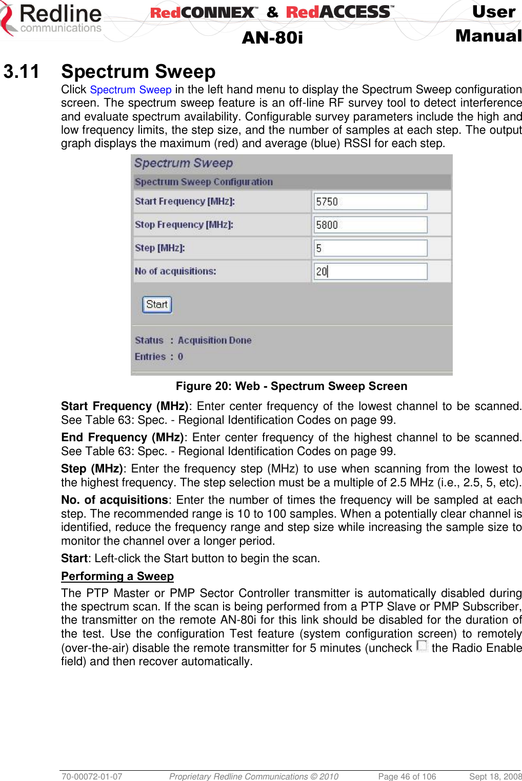
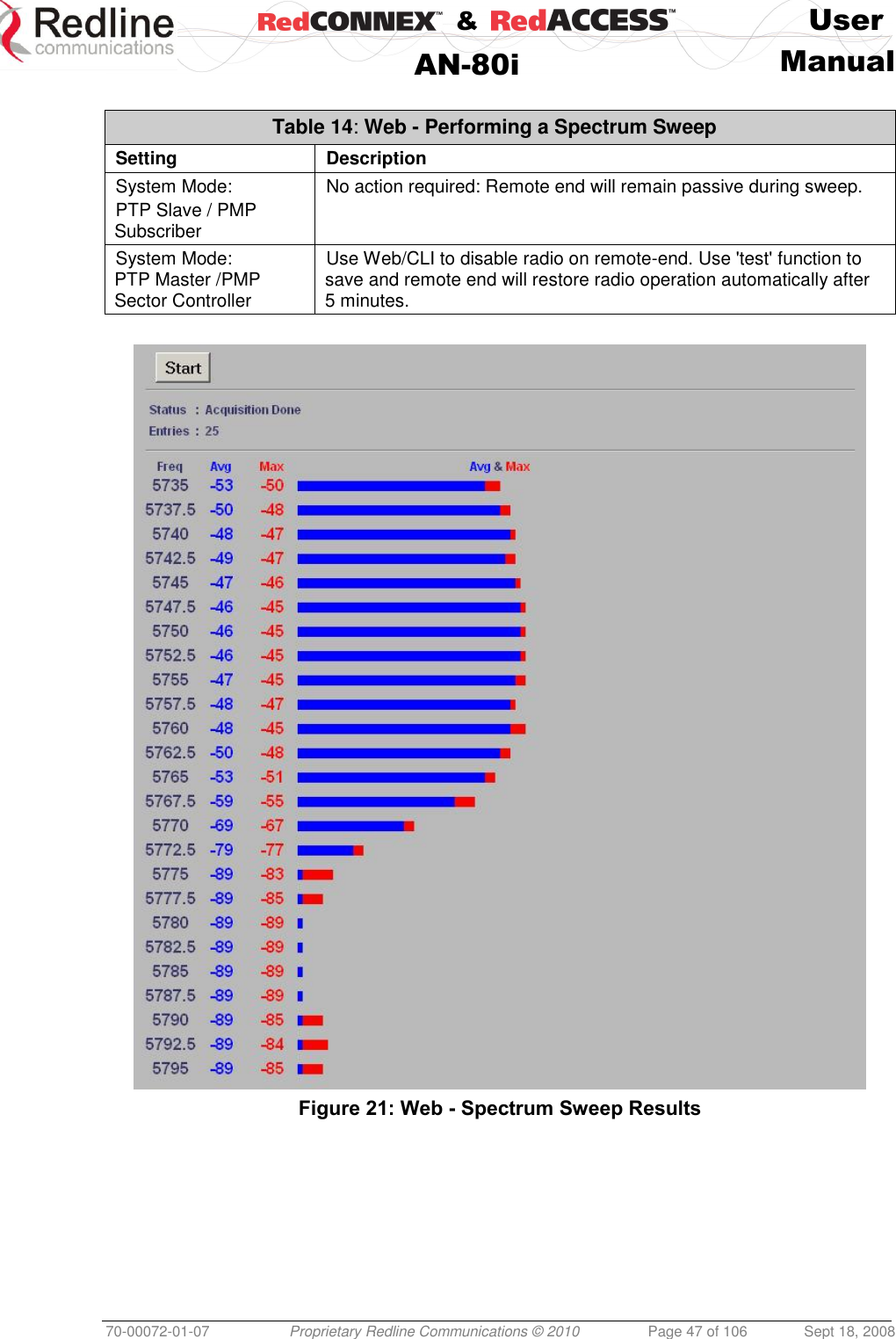
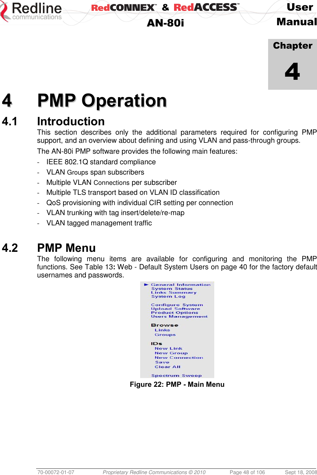
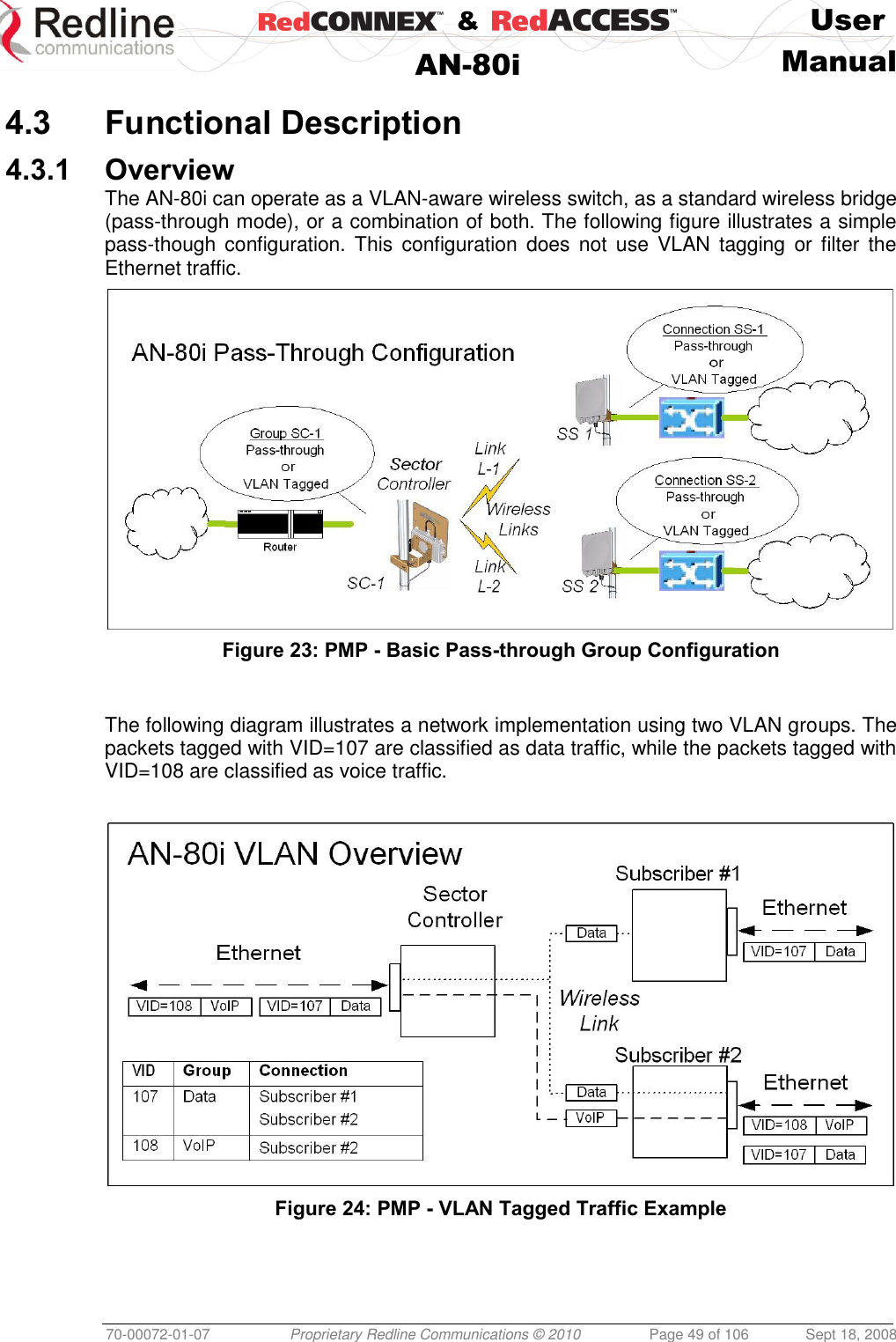
![& User AN-80i Manual 70-00072-01-07 Proprietary Redline Communications © 2010 Page 17 of 106 Sept 18, 2008 Warning to Service Personnel: 48 VDC Customer equipment including personal computers, routers, etc., must be connected only to the INPUT (DATA) port on the PoE unit. Only the outdoors Ethernet interface cable connecting to the AN-80i can be safely connected to the OUTPUT (DATA & POWER) connector. Connecting customer premises Ethernet equipment directly to the OUTPUT (DATA & POWER) connector on the Power-over-Ethernet power adapter may damage customer equipment. 2.6 Antenna Alignment The AN-80i includes both an audible alignment tool and a web-based alignment tool to assist in pointing the antenna. 2.6.1 Web Page Alignment The most reliable method for obtaining optimum performance from a wireless link is to align the antenna to the position providing the highest RSSI value and the best SINADR ratio. The web page alignment tool provides continuous updates (1 second intervals) of the measured RSSI (received signal strength indication) and SINADR (Signal to noise and distortion ratio). This web page can be accessed from a laptop computer and most web-enabled handheld devices. Use the following URL to access the AN-80i alignment web page: http:// [AN-80i IP Address] / usr / aa.html For example: http://192.168.20.30/usr/aa.html 2.6.2 Audible Alignment The signal will sound infrequently when a low signal is detected, and more often as the signal strength increases. The audible signal is enabled and disabled through the user interface: Web: See Antenna Alignment Buzzer Enable under Wireless Configuration on page 33. Telnet: See buzzer in CLI Set commands under Set on page 73. The audible antenna alignment tool provides only rough adjustment for the subscriber antennas. It is recommended to monitor the RSSI measurements to achieve maximum signal strength when performing fine adjustments to the subscriber antenna. Refer to the AN-80i Installation Guidelines for detailed instructions.](https://usermanual.wiki/Redline-Communications/AN80IE.user-manual/User-Guide-1282965-Page-17.png)
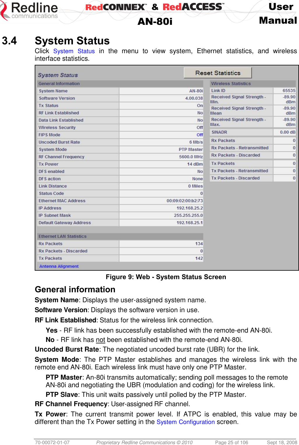
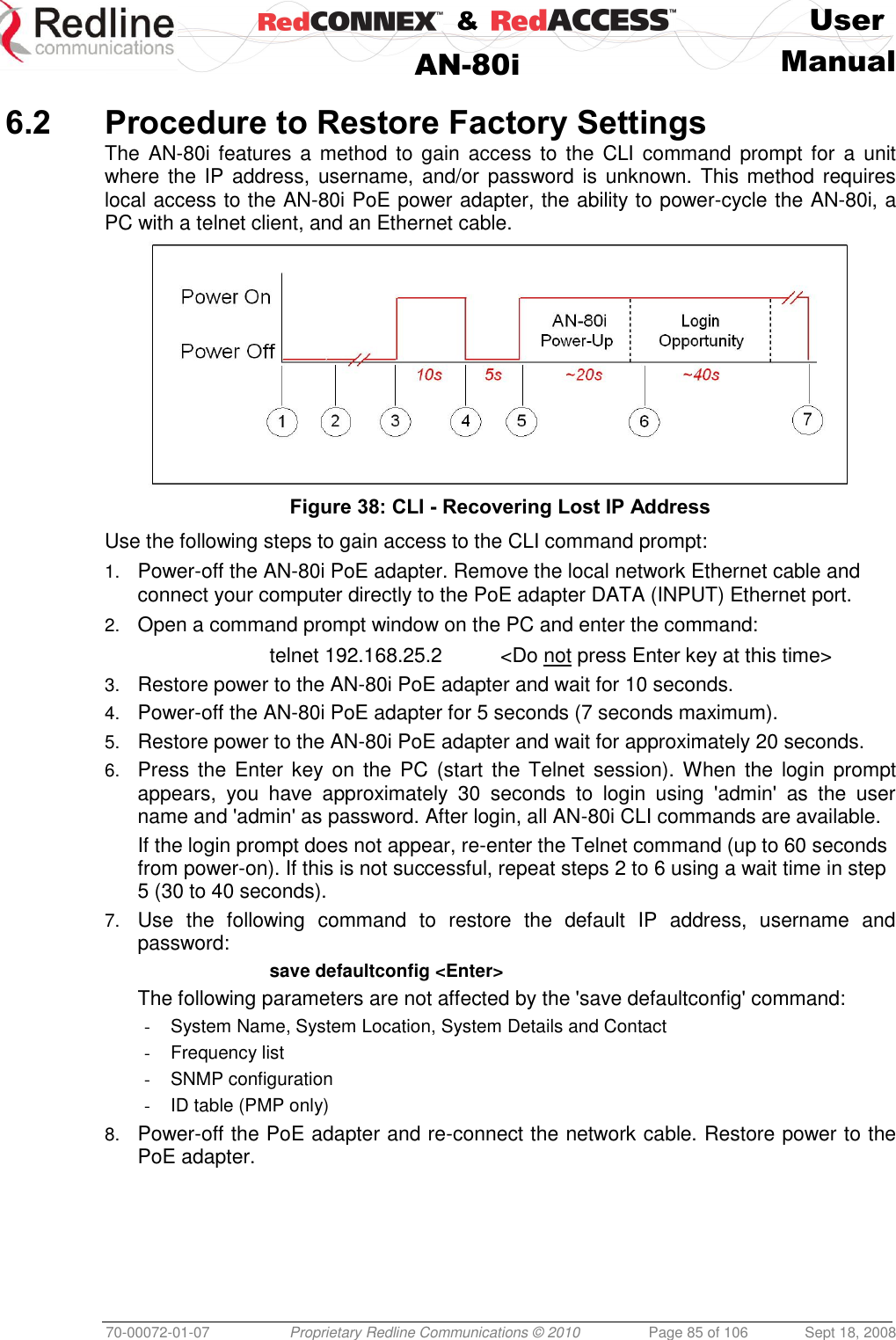
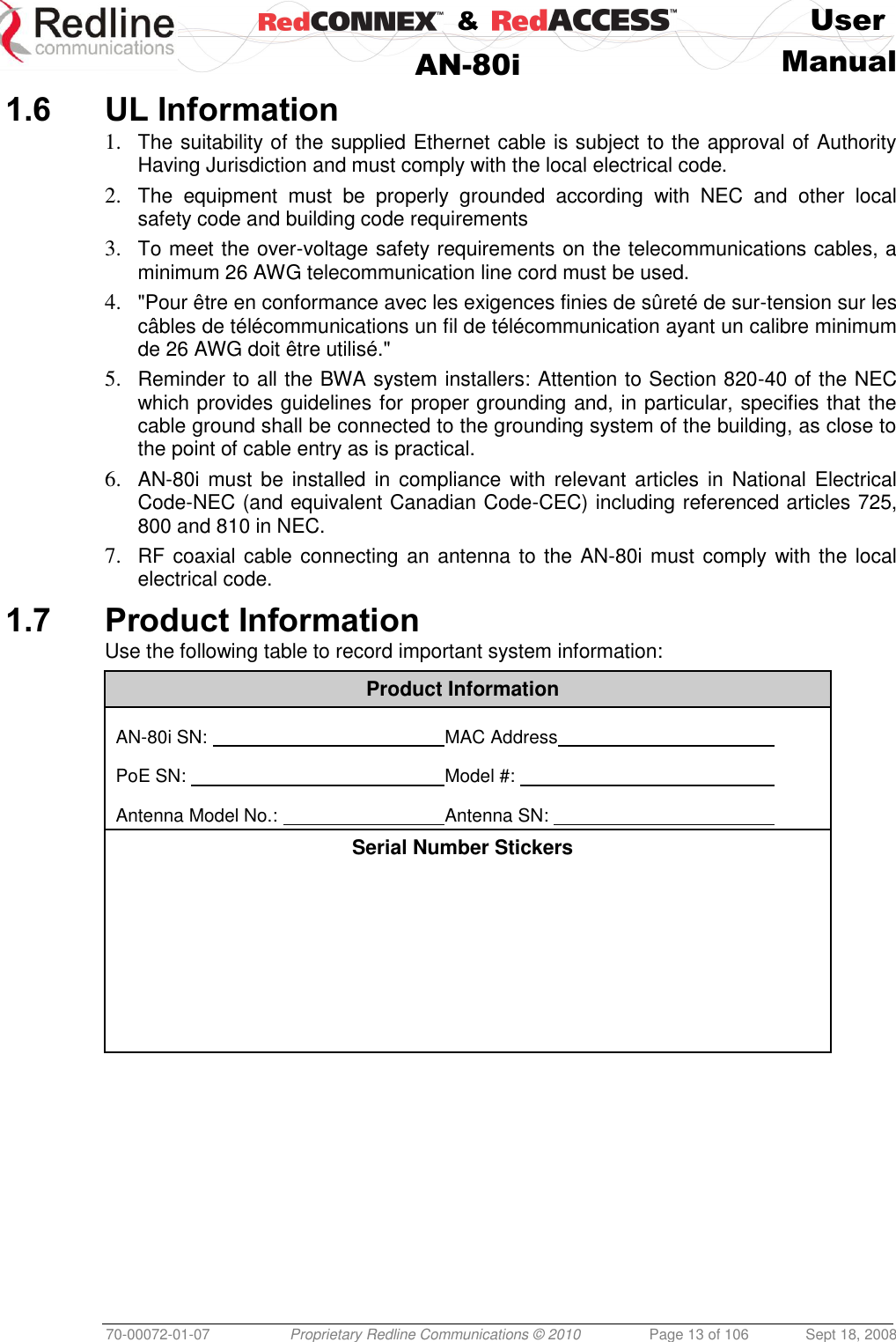
![& User AN-80i Manual 70-00072-01-07 Proprietary Redline Communications © 2010 Page 26 of 106 Sept 18, 2008 DFS Enabled: Indicate the status of the DFS feature. Refer to the Wireless Configuration section on page 33 for a complete description of the DFS feature. Enabled: The DFS feature is activated. See DFS Action below. Disabled: The DFS feature is disabled. DFS Action: Indicates the last DFS action taken by the AN-80i equipment. All DFS actions are recorded in the event log. None: The DFS feature is disabled. Tx Off: Transmitter was switched off for 30 minutes. Chg Freq: Transmitter was switched to a different frequency. Link Distance [Miles or Km]: Distance between wireless systems. This may be the calculated or user-assigned distance (System Configuration screen). Status Code: Code indicating the condition of the AN-80i system. Status indications are specific for PMP and PTP operation. Ethernet MAC Address: System hardware address (also printed on product label). IP Address: User-assigned IP address of the AN-80i. IP Subnet Mask: User-assigned IP subnet mask. Default Gateway Address: User-assigned IP for the default router or gateway. Ethernet LAN Statistics Rx Packets: Total packets received on the Ethernet port. Rx Packets: Discarded: Total valid Ethernet frames received on the Ethernet port that are discarded due to lack of buffer space. Tx Packets: Number of packets transmitted on the Ethernet port (including Ethernet frames and error correction bytes). Wireless Statistics Link ID: A unique Link ID value is generated automatically when a new link is added. Received Signal Strength: Min: Minimum measured RSSI value. Received Signal Strength: Mean: Average measured RSSI value. Received Signal Strength: Max: Maximum measured RSSI value. SINADR: Ave. signal to interference, noise, and distortion ratio measured since last refresh. Rx Packets: Total number of packets received over the wireless interface. Rx Packets: Retransmitted Number of wireless packets received that were retransmitted by the remote-end system (ARQ mechanism re-transmitting unacknowledged packets). Rx Packets - Discarded: Number of received packets discarded due to errors. Tx Packets: Number of packets transmitted over the wireless interface. Tx Packets - Retransmitted: Number of packets re-transmitted over the wireless interface (ARQ mechanism re-transmitting unacknowledged packets). Tx Packets: Discarded: Total number of packets transmitted over the wireless interface that were not acknowledged (discarded by remote-end due to errors). Controls Reset Statistics: Click this button to zero the counters for the wireless and Ethernet LAN Statistics displayed on this page.](https://usermanual.wiki/Redline-Communications/AN80IE.user-manual/User-Guide-1282965-Page-26.png)
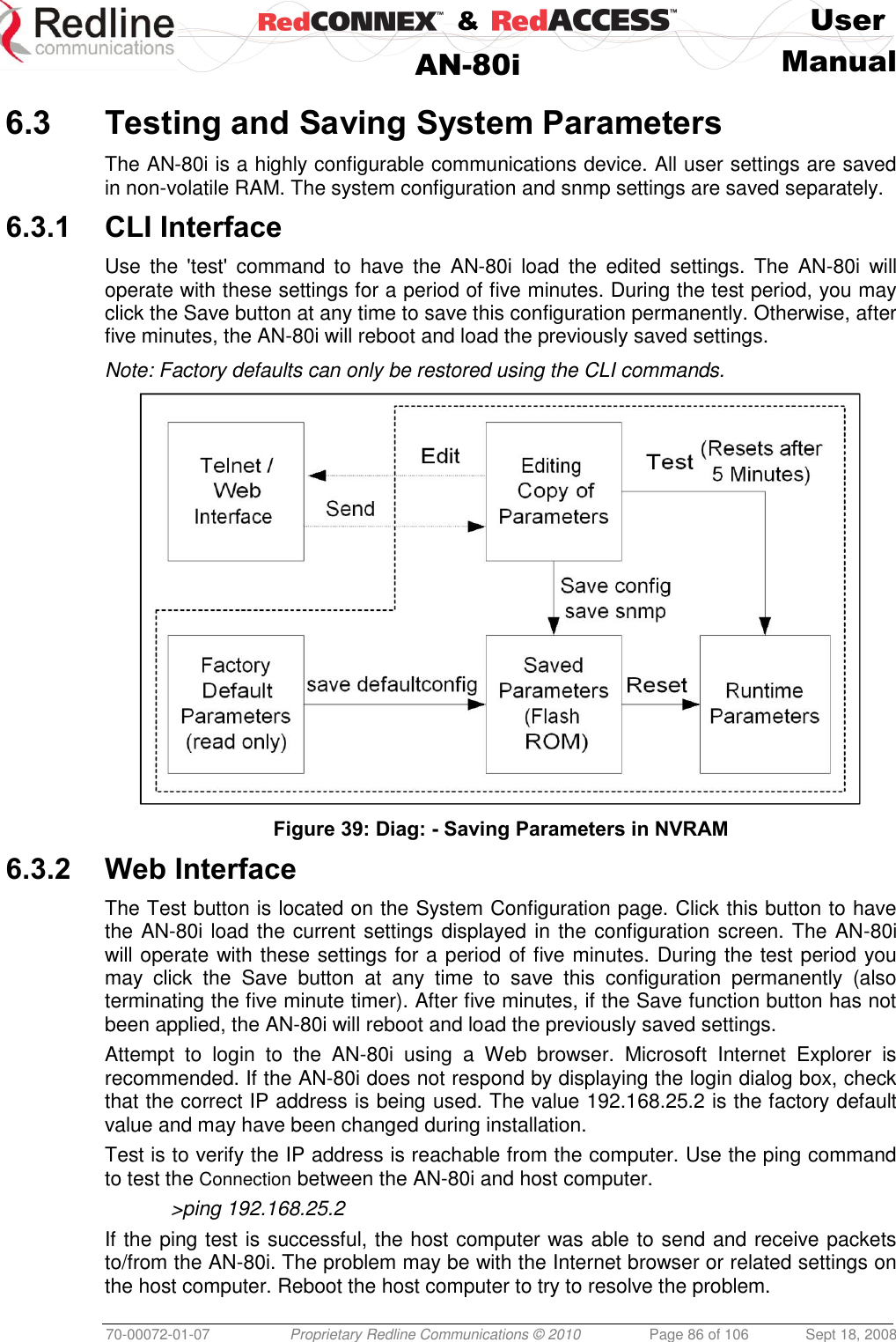
![& User AN-80i Manual 70-00072-01-07 Proprietary Redline Communications © 2010 Page 32 of 106 Sept 18, 2008 HTTP Enable: Check this box to enable the HTTP (Web) interface. If the option is deselected, only CLI commands will be available. Telnet Enable: Check this box to enable a Telnet access (CLI) to the AN-80i. Refer to the CLI commands in CLI Interface on page 66. Telnet Port: Enter Telnet port address (default is 23). SNMP Enable: Check this box to enable the Simple Network Management Protocol (SNMP) agent. When this item is checked, click on the blue text [Configure SNMP] adjacent to the check box to display the SNMP Configuration screen. Mgmt. Tag Enable: Check this box to enable VLAN tagged traffic. The Mgmt Tag Enable setting is disabled (factory default) when shipped from the factory or following a long-reset operation. In this mode the PTP Master and PTP Slave can be managed through the local Ethernet port using untagged traffic. Over-the-air management is possible only after creating a pass-through group and pass-through connections for each PTP Slave. When Mgmt Tag Enable is enabled, this PTP Master or PTP Slave can be managed only using VLAN traffic tagged with the value specified in the Mgmt. VID field. Over-the-air management is possible only after creating a VLAN tagged group and VLAN tagged connections for each PTP Slave. It is recommended to create and test a VLAN group for tagged management traffic before activating the Mgmt Tag Enable function. Set the associated QoS and priority values to ensure management traffic has adequate priority and bandwidth during system operation. Mgmt. VID: Enter the VLAN ID. When Mgmt. Tag Enable is selected, the system recognizes only management commands with this VLAN ID. Important: The VLAN network support should be verified before enabling this feature to ensure the AN-80i system will be reachable using the VLAN tagged traffic.](https://usermanual.wiki/Redline-Communications/AN80IE.user-manual/User-Guide-1282965-Page-32.png)
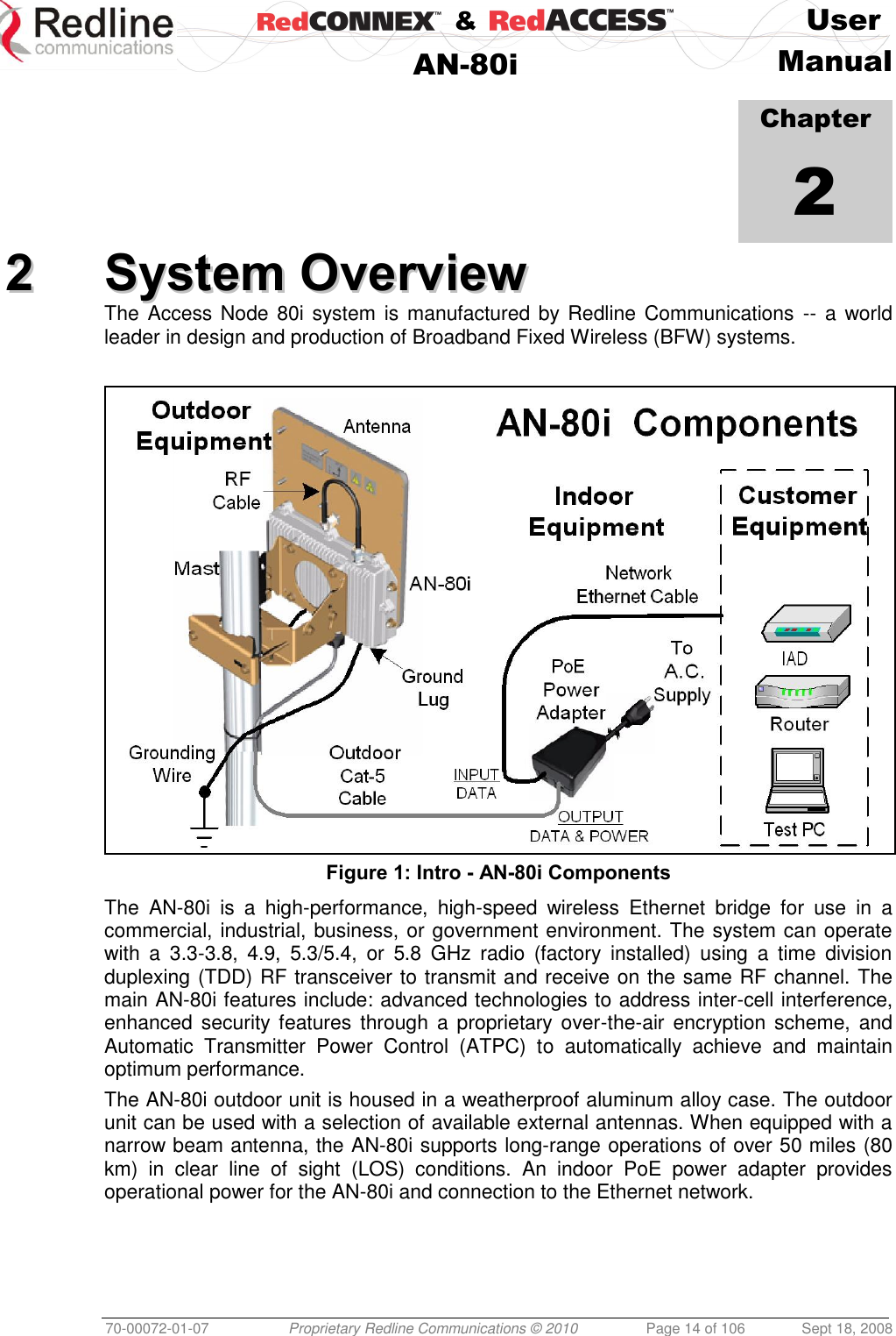
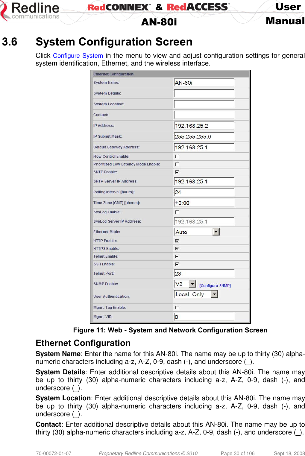
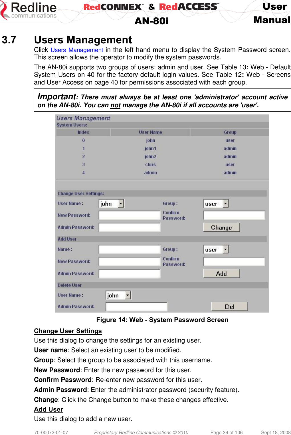
![& User AN-80i Manual 70-00072-01-07 Proprietary Redline Communications © 2010 Page 33 of 106 Sept 18, 2008 Wireless Configuration Use settings on the following screen to configure the AN-80i wireless interface. Figure 12: Web - Wireless Configuration Screen RF Freq. [MHz]: Enter the center frequency for the RF channel. This setting must be identical for both AN-80i systems operating as a wireless link. The options key controls channel availability. Refer to Table 63: Spec. - Regional Identification Codes on page 99 for available channels. Use the Autoscan feature to enable use of multiple channels. When the Auto Scan field is not checked, the PTP Slave will only register with a PTP Master operating at the frequency specified in the RF Freq. [MHz] field. Important: To minimize interference, the channel frequencies for AN-80i links operating in close proximity should be separated by a minimum of the channel size in use (to avoid overlapping bands). Auto scan: Check this box to enable the PTP Slave automatically scan available channels to locate and register with an AN-80i PTP Master. When the Auto Scan field is checked, click on the blue text [Frequency Ranges] adjacent to the check box to display](https://usermanual.wiki/Redline-Communications/AN80IE.user-manual/User-Guide-1282965-Page-33.png)
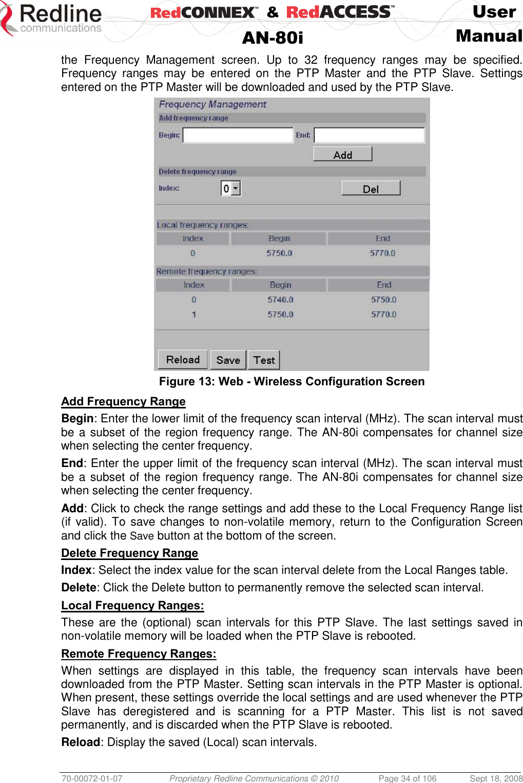
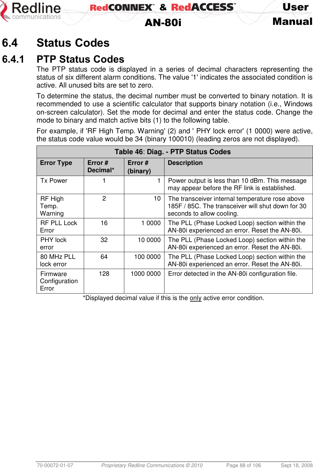
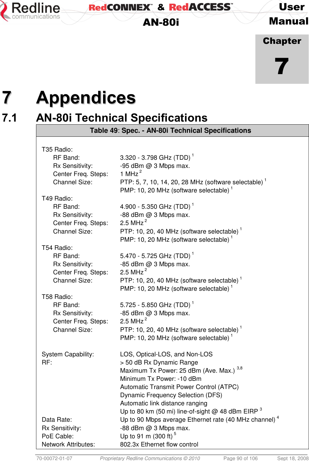
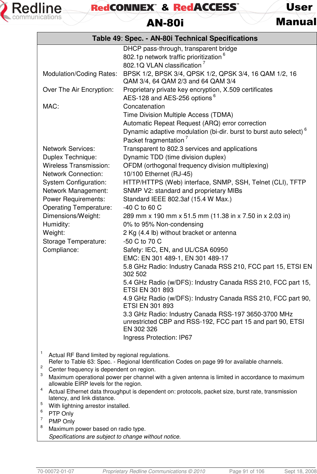
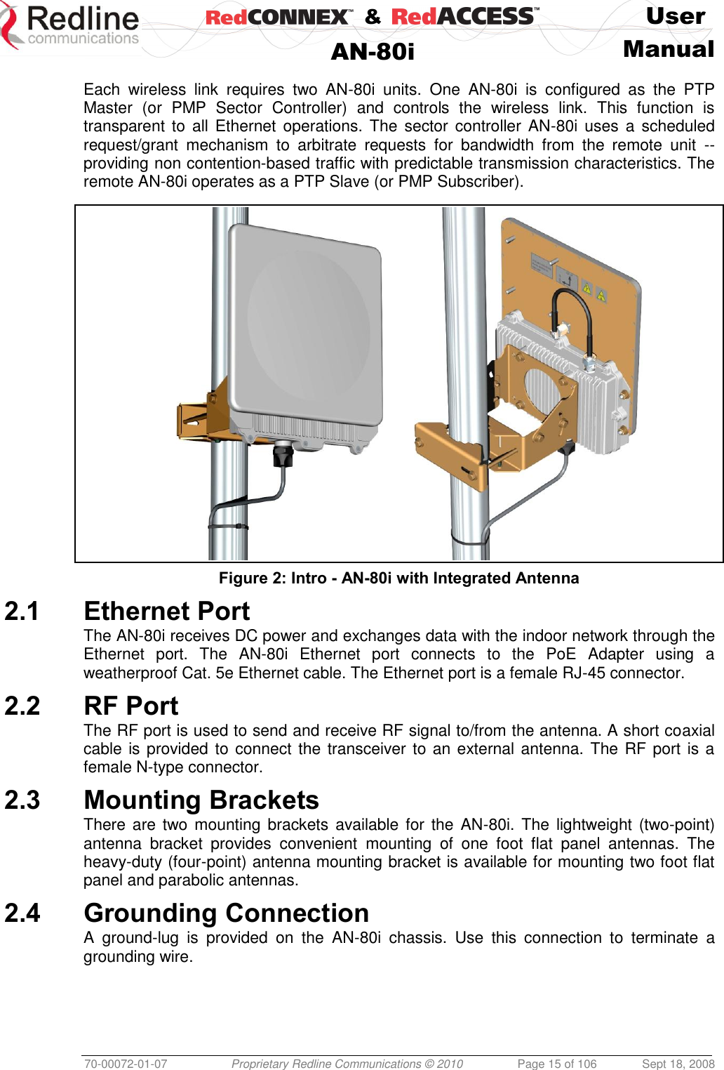
![& User AN-80i Manual 70-00072-01-07 Proprietary Redline Communications © 2010 Page 35 of 106 Sept 18, 2008 Save: If settings are valid, the ranges are added to the Local Frequency Range list. An event message is logged indicating the results of the test. Important: Clicking the Save button does not permanently save changes. You must click Save at the bottom of the System Configuration screen. Test: Click to check the range settings and add these to the Local Frequency Range list (if valid). This action does not save the changes to non-volatile memory. Operating Notes If no scan intervals are defined, the PTP Slave will scan all frequency ranges for the enabled region. If scan intervals are defined, only the listed channels will be scanned for a PTP Master. If the PTP Slave checks all scan intervals three times without locating and registering with a PTP Master, the scanning mode is changed to include all frequency ranges for the enabled region (until registration or reboot). The PTP Master can also be programmed with a list of scan intervals. When the PTP Slave registers with a PTP Master that has frequency ranges defined, the list is transmitted to the PTP Slave and is displayed as Remote Frequency Ranges. When present, the scan intervals in the Remote Frequency Ranges table are used exclusively during autoscan (Local Frequency Ranges are ignored). The Remote Frequency Ranges remain in effect until the PTP Slave is rebooted. Tx Power [dBm]: Enter the transmit power level (dBm). This setting is for the transceiver output only. The actual EIRP depends on the gain of the connected antenna. Refer to the following tables to determine the maximum transmit power level available at each modulation setting. When ATPC is enabled, the Tx power is automatically adjusted to achieve optimum performance. When DFS is enabled, the subscriber Tx power may be automatically adjusted (regardless of ATPC setting) to avoid false DFS triggering. Table 10: Maximum TX Power Settings (dBm) for AN-80i Radio Modulation BPSK QPSK 16 QAM 64 QAM Code Rate 1/2 3/4 1/2 3/4 1/2 3/4 2/3 3/4 Max. Tx Power: T35 Radio 25 25 25 25 25 23 22 21 Max. Tx Power: T49 / T54 / T58 Radio 25 25 23 22 21 20 18 17 PTP: v3.00 or higher / PMP: v11.0 or higher . Note: In PMP mode, setting the Tx power too high may reduce the SINADR value. If the SINADR is less than expected, re-test the link using a lower Tx power setting. Important: EIRP Levels: Where required by local regulations, the maximum operational power per channel for a specific antenna must not exceed the maximum allowable EIRP levels. Refer to the FCC and CE notices in this manual. The RF output power settings must be professionally programmed by the manufacturer or a trained professional installer. See section 7: Appendices for a list the maximum transmit power setting based on the antenna gain for a series of frequency settings.](https://usermanual.wiki/Redline-Communications/AN80IE.user-manual/User-Guide-1282965-Page-35.png)
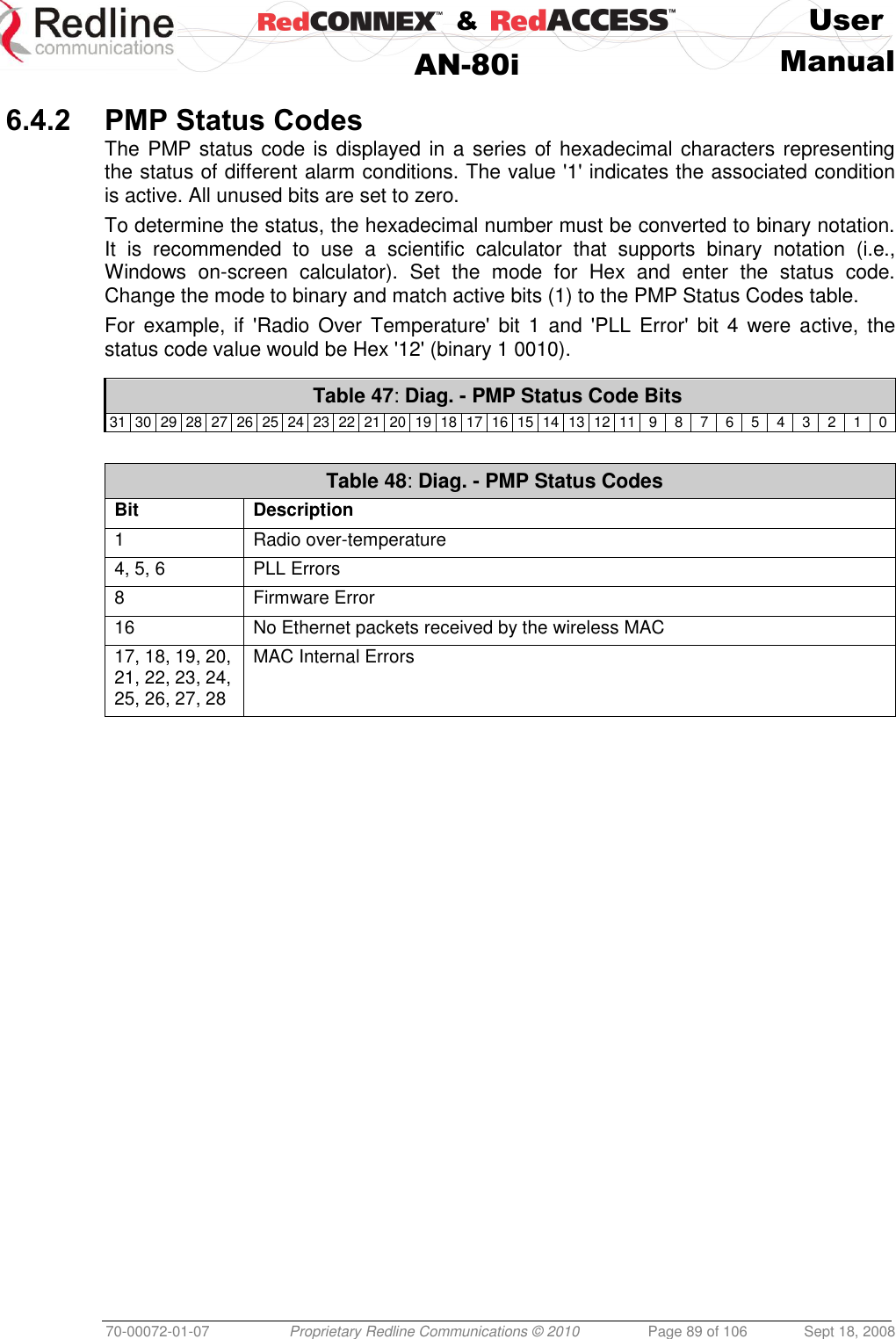
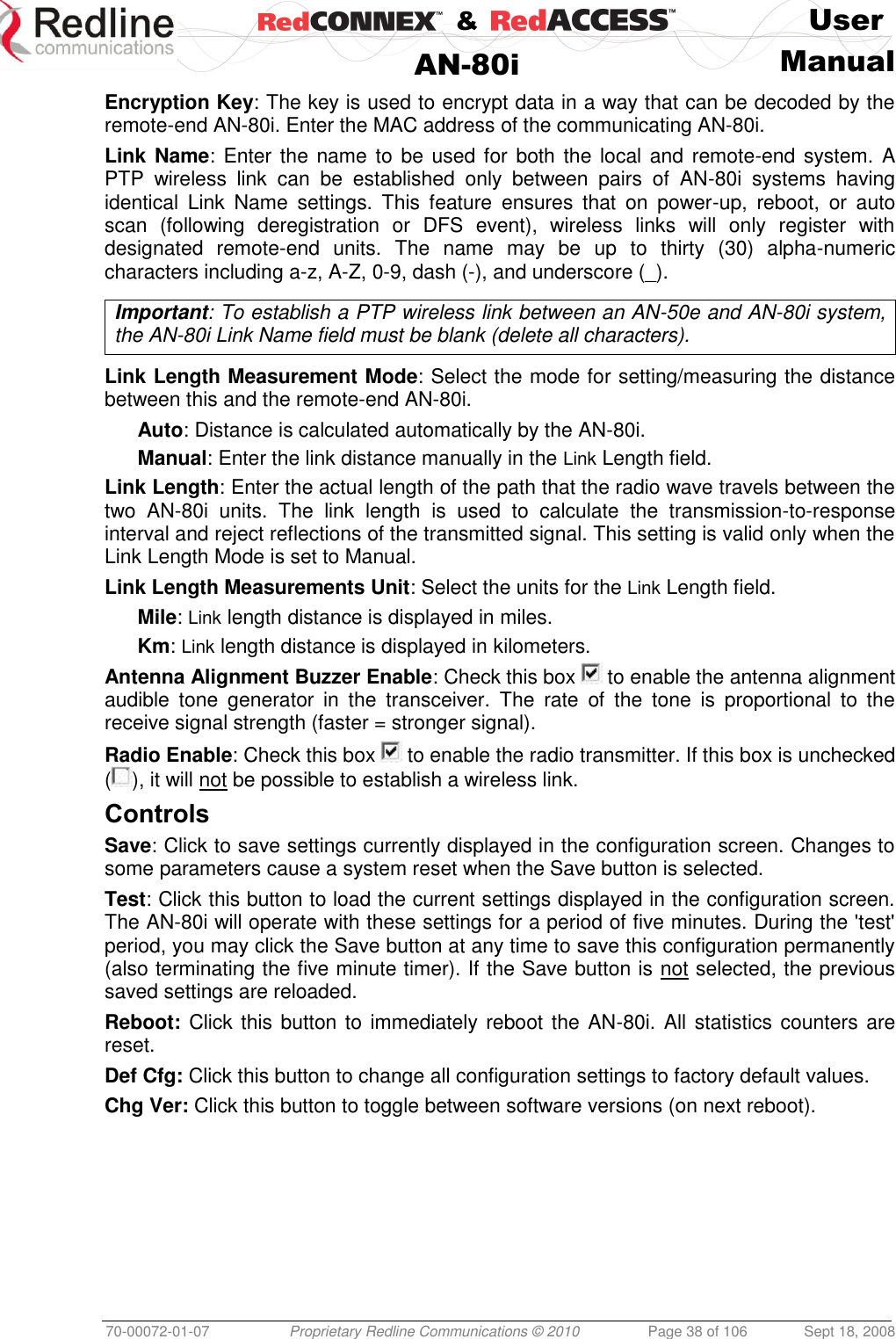
![& User AN-80i Manual 70-00072-01-07 Proprietary Redline Communications © 2010 Page 37 of 106 Sept 18, 2008 Uncoded Burst Rate [Mb/s]: Select the desired UBR for the link. If Adaptive Modulation is disabled, the AN-80i will transmit using only the specified settings. See Table 10: Maximum TX Power Settings (dBm) for AN-80i Radio. Channel Width [MHz]: Select the channel bandwidth. Refer to Table 63: Spec. - Regional Identification Codes on page 99 for available channel widths. Ethernet Follows Wireless: Check this box to have the AN-80i disable and enable the Ethernet port function based on the status of the wireless interface. This feature allows switches and routers to trigger configuration changes based on changes to the AN-80i Ethernet port status. Disabled ( ): The AN-80i Ethernet port is always enabled. Enabled ( ):Ethernet port is controlled based on the status of the wireless interface. Table 11: Web - Ethernet Status Indication Wireless interface Status Ethernet Port Status Link Up Enabled Link Down Disabled Important: The Ethernet Follows Wireless setting affects all data and management traffic (HTTP, TELNET, and SNMP). While activated, it is not possible to manage the AN-80i using the Ethernet port. Ethernet follows wireless timeout [sec]: Enter the period (in seconds) the Ethernet port will remain disabled following loss of connectivity on the wireless interface. Following this interval, the Ethernet port will be automatically re-enabled to allow management of the AN-80i. Important: When Ethernet Follows Wireless Timeout is enabled, external switches/routers monitoring the Ethernet port must be programmed to not switch automatically when the Ethernet port function is restored -- the wireless interface may not be operational. System Mode: Set the operating mode for each AN-80i system. PTP Master: This unit begins transmitting automatically; sends poll messages to the remote AN-80i, and negotiates the wireless link. PTP Slave: This unit waits passively, monitoring the selected channel(s) until polled by the PTP Master, and participates in negotiating the wireless link. Software Version: Select the version of system software to load when the AN-80i is rebooted. The system holds two independent software images. Encryption Type: Select an encryption type for data transmitted over the wireless interface. When encryption is enabled, no Ethernet packets can be transferred over-the-air unless encryption is enabled on the remote-end AN-80i and the correct Encryption Key is entered on both AN-80i units. None: Encryption is disabled. Redline 64-bit: Redline proprietary encryption scheme, compatible with AN-50e. AES 128-bit: Advanced Encryption Standard using 128-bit encryption. AES 192-bit: Advanced Encryption Standard using 192-bit encryption. AES 256-bit: Advanced Encryption Standard using 256-bit encryption.](https://usermanual.wiki/Redline-Communications/AN80IE.user-manual/User-Guide-1282965-Page-37.png)
![& User AN-80i Manual 70-00072-01-07 Proprietary Redline Communications © 2010 Page 50 of 106 Sept 18, 2008 4.3.2 Minimum Setup Requirements A minimum set of parameters must be configured to enable data and management traffic on any PMP deployment: 1. Create one or more Links to identify each subscriber in the sector, and set the wireless link operating characteristics, including the maximum uplink and downlink modulation. 2. Create one or more Groups (VLAN or pass-through) and set the operating characteristics of this group. 3. Create one or more Connections (to Groups) for each subscriber, to assign membership to at least one Group. The following table provides a summary of the configuration shown in the pass-through configuration diagram above. The actual Group ID and Link ID values are not available until these items have been created during configuration of the system. This configuration passes all data traffic as a standard PMP configuration. Table 15: PMP - Basic Pass-Through Group Settings Group Configuration (Sector Controller) Connection Configuration (Subscriber) Group Name Port Tagging Group VID Connection Name Port Tagging Link ID Group ID Connection VID SC-1 Pass Through NA SS-1 Pass Through [L-1] [SC-1] NA SS-2 Pass Through [L-2] [SC-1] NA Notes: 1. The Group ID, Conn ID, and Link ID values are assigned automatically and must be read from the screen after items are created. 2. The QoS settings must be determined using the PMP Configuration Tool. 4.3.3 Packet Classification The AN-80i PMP deployment can be configured for use with VLAN tagged traffic, untagged traffic, or a combination these two types. Ingress packets received on the Ethernet port are classified into tagged or pass-through groups according to the criteria in the following table. The Group settings apply to packets processed at the sector controller, while Connection settings apply to packets processed at the subscriber. Table 16: PMP - Packet Classification Type Description Tagged Traffic Packet has a VLAN tag and there is a Group/Connection configured for this VID. Sector Controller: Packets are forwarded over the wireless link to all subscribers with Connections to this VLAN Group. Subscribers: Packets are forwarded to the sector controller. The sector controller forwards the packets to the local Ethernet port and subscribers with Connections to this VLAN Group. Pass-Through Traffic The packet does not have a VLAN tag, or no Group/Connection exists for this VID. If a pass-through Group has not been defined, unclassified packets are discarded. If a pass-through Group has been defined, classified packets are forwarded based on the rules for tagged traffic. The packet VLAN information is not modified.](https://usermanual.wiki/Redline-Communications/AN80IE.user-manual/User-Guide-1282965-Page-50.png)
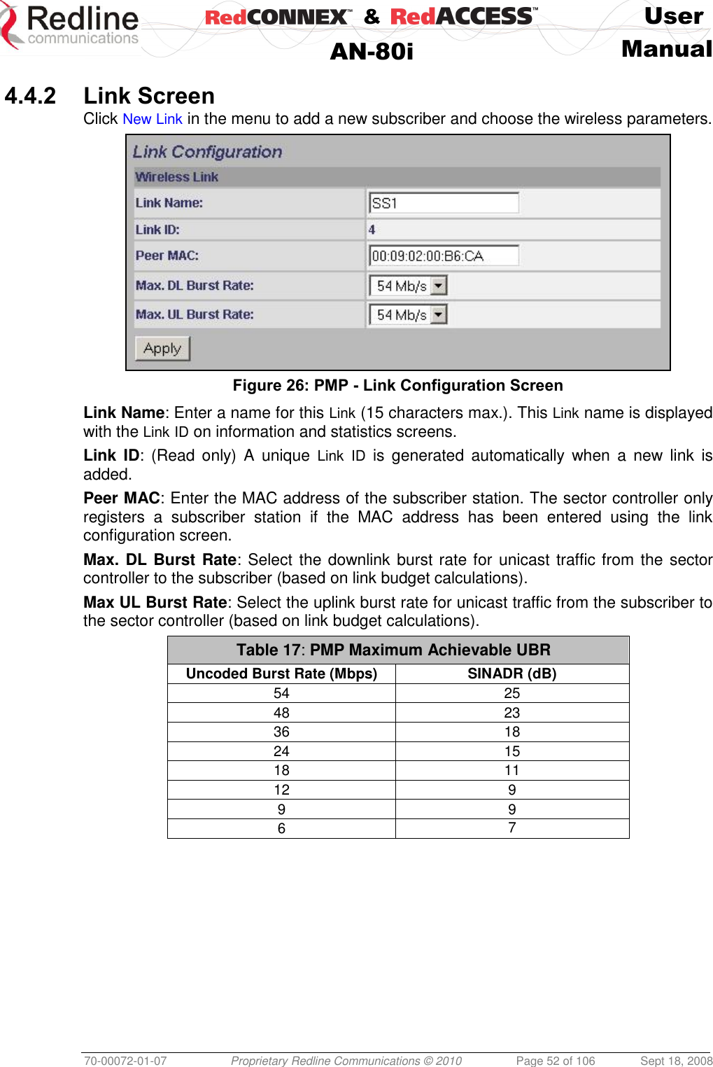
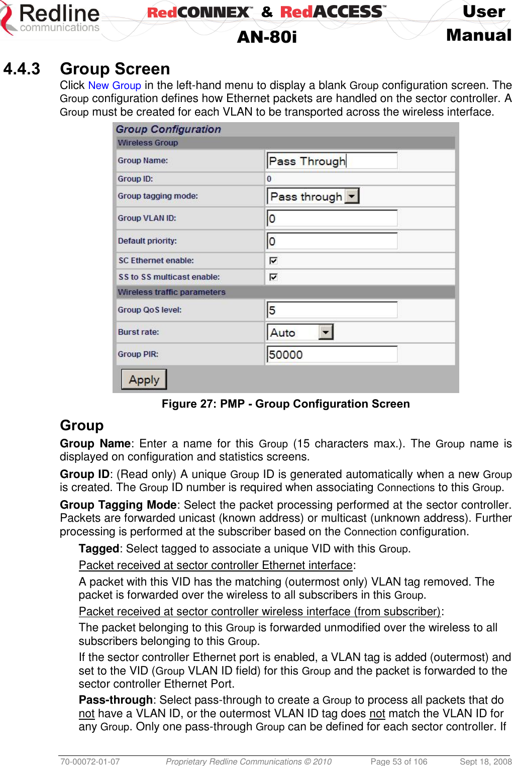
![& User AN-80i Manual 70-00072-01-07 Proprietary Redline Communications © 2010 Page 51 of 106 Sept 18, 2008 4.4 PMP Screens This section describes the configuration screens used to setup a PMP deployment. 4.4.1 Configuration Screen Click Configure System in the menu to view and adjust configuration settings for general system identification, Ethernet, and the wireless interface (partial screen shown below). The highlighted wireless settings are specific to PMP deployments. Figure 25: PMP - Wireless Settings System Mode: The system designated as sector controller establishes and manages the bi-directional data link with a remote end AN-80i. Only one system in a wireless link must be set for Sector Controller mode. PTP Sector Controller: AN-80i begins transmitting automatically, sends poll messages to locate remote AN-80i subscribers, and negotiates operating settings for the link. PTP Subscriber: AN-80i waits passively, monitoring the selected channel(s) until polled by the PTP Sector Controller. Registration Period: The polling period for detecting new subscribers. Period is based on the number of wireless frames transmitted. Permitted values are 1 to 400. The recommended default registration period is 4. Max. Distance [km]: Enter the distance to the subscriber located farthest away from the sector controller (outer boundary of sector). This parameter is used to optimize communications with the subscribers.](https://usermanual.wiki/Redline-Communications/AN80IE.user-manual/User-Guide-1282965-Page-51.png)
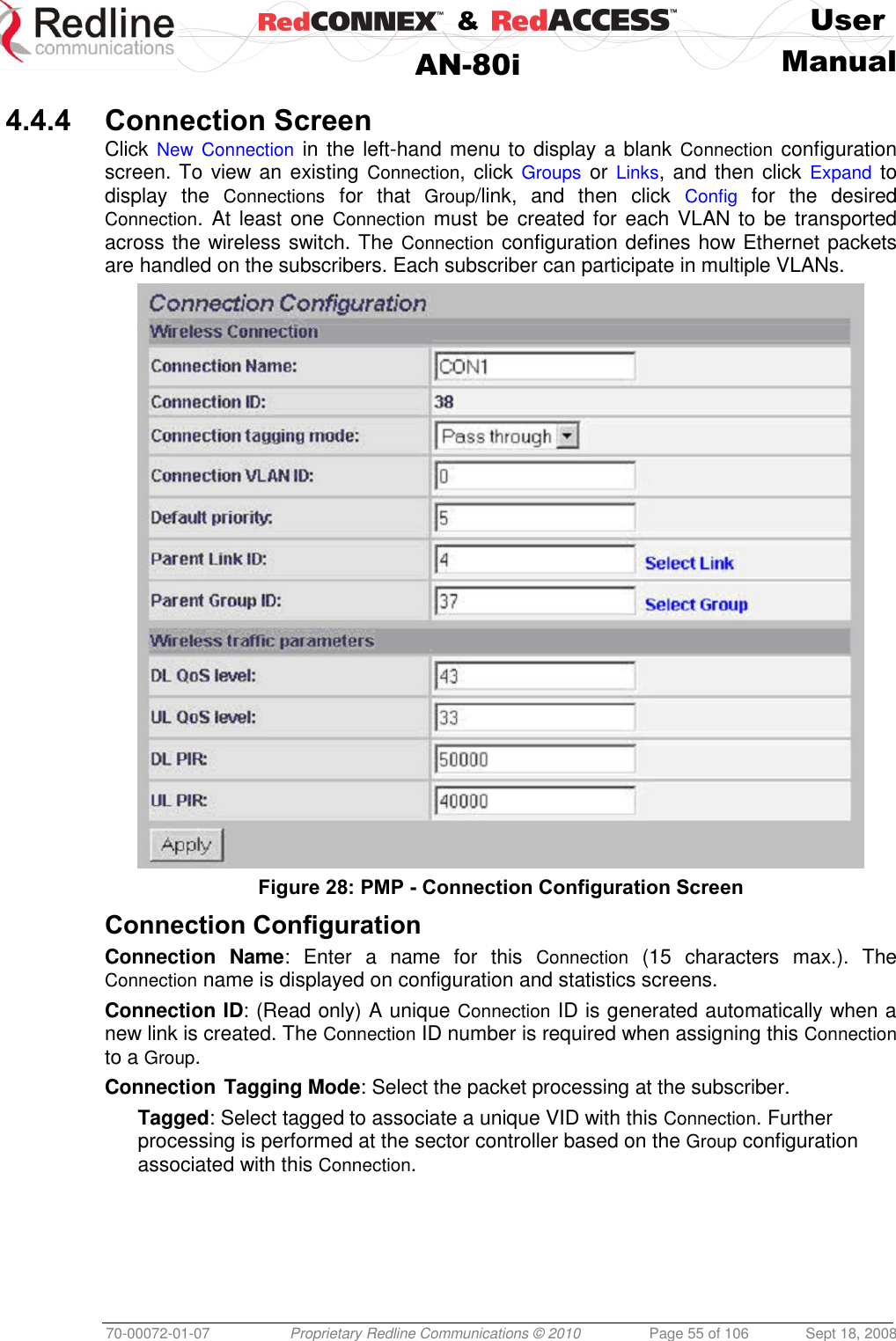
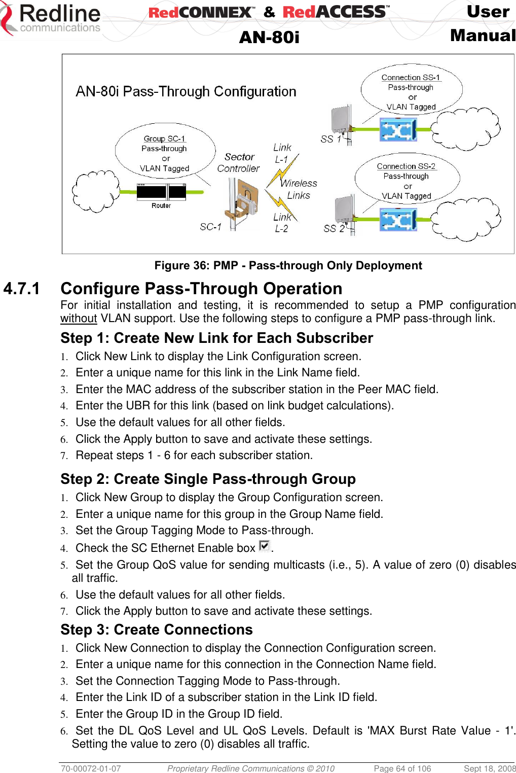
![& User AN-80i Manual 70-00072-01-07 Proprietary Redline Communications © 2010 Page 65 of 106 Sept 18, 2008 7. Click the Apply button to save and activate these connection settings. 8. Repeat steps 1 - 7 to add a connection for each subscriber station. Step 4: Save Configuration Click Save in the left-hand menu to permanently save all settings. The system will pass all tagged and untagged data and management traffic. The following table provides sample settings for a pass-though group at the sector controller and connections to two subscriber stations. Table 18: PMP - Basic Pass-Through Group Configuration Settings Group Configuration (SC) Connection Configuration (SS) Group Name Group Tagging Mode Group VLAN ID Connection Name Connection Tagging Mode Link ID Group ID Connection VLAN ID SC-1 Pass Through NA SS-1 Pass Through [L-1]* [SC-1]* NA SS-2 Pass Through [L-2]* [SC-1]* NA *The group ID and link ID are numbers generated automatically by the AN-80i. 4.7.2 VLAN Configuration Use these steps to convert the system from pass-through operation to VLAN tagged connections. Step 1: Change Group to VLAN Tagged 1. Click Groups to display the Groups Configuration screen. 2. Click Config to edit the Group configuration. 3. Set the mode to Tagged in the Group Tagging Mode field. 4. Enter the VID for this group in the Group VLAN ID field. 5. Click the Apply button to save and activate these settings. Step 2: Change Connections to VLAN Tagged 1. Click Groups in the menu to display the Groups Configuration screen. 2. Click Expand to view all connections for that Group. 3. Choose a connection and click Config to edit the Connection Configuration. 4. Set the mode to Tagged in the Connection Tagging Mode field. 5. Enter the VLAN ID for this connection in the Connection VLAN ID field. 6. Click the Apply button to save and activate these settings. 7. Repeat steps 1 through 6 for each Connection in the Group. Step 3: Save Configuration Click Save in the left-hand menu to permanently save and activate all settings. The system will now pass only VLAN tagged traffic.](https://usermanual.wiki/Redline-Communications/AN80IE.user-manual/User-Guide-1282965-Page-65.png)
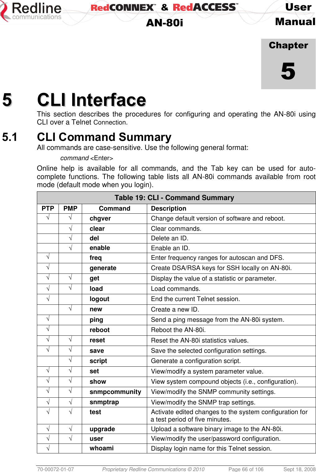
![& User AN-80i Manual 70-00072-01-07 Proprietary Redline Communications © 2010 Page 67 of 106 Sept 18, 2008 Table 20: CLI - Root Mode Commands PTP PMP Command Description √ √ Tab When entering a command, hit the Tab key at any time to perform auto-complete or view available options. √ √ ? Use the '?' character to display help for any command or mode. Example: From the root directory, enter the following command to list all parameters that can be changed using the 'set' command: set ? √ √ CTRL-Z Return to root mode. Cancel command entry (alternative to backspace delete). √ √ exit Return to parent node / mode. all (exit all) Return to root mode. √ √ logout Terminate this telnet session. May be entered from any mode. 5.2 Connecting with Telnet To connect to the AN-80i, open a Telnet session to the IP address of the AN-80i. On a Windows™ PC, open the Run command and type 'telnet' followed by the IP address of the AN-80i. When the command prompt screen appears, login to the AN-80i. The AN-80i may now be controlled using a set of CLI commands. Figure 37: CLI - Connecting via Telnet The system will logout users automatically if no commands are received (idle) for five minutes. To exit immediately from the CLI, type the following command: logout [ENTER] The AN-80i supports two concurrent Telnet sessions. One session has full capabilities and the second session is read-only (e.g., monitor or show parameter settings). 5.3 CLI Command Set 5.3.1 Chgver Use the chgver command to change the software version loaded when the AN-80i is rebooted. Table 21: CLI - chgver PTP PMP Parameter/Description √ √ Enter this command to toggle between software versions. The setting will alternate between the two banks of memory (no parameters). chgver <Enter>](https://usermanual.wiki/Redline-Communications/AN80IE.user-manual/User-Guide-1282965-Page-67.png)
![& User AN-80i Manual 70-00072-01-07 Proprietary Redline Communications © 2010 Page 68 of 106 Sept 18, 2008 5.3.2 Clear Use the clear command to delete all IDs from an ID table. Table 22: CLI - clear PTP PMP Parameter/Description √ Enter this command to delete all IDs from an ID table. clear <idtable> idtable - Clear all the IDs 5.3.3 Del Use the del command to delete a specific ID or security key/certificate. Table 23: CLI - del PTP PMP Parameter/Description √ del <id> Remove a group, connection, or link id. id number <integer> Unique number for group, connection, or link. √ Del <file> file <name> <mode> Remove a file from flash and runtime memory. <name> File name on server. File name must be one of the following: dsa_key_<mac>.pem DSA key used for SSH. rsa_key_<mac>.pem RSA Key used for SSH. ssl_cert_<mac>.pem SSL Certificate. ssl_key_<mac>.pem SSL Key. usr_wcert_<mac>.der* User wireless certificate. usr_wkey_<mac>.der* User wireless key. usr_wacert_<mac>.der* User wireless authority certificate The <mac> portion is the MAC address of the board. For example: dsa_key_00-09-02-00-01-02.pem <mode> Can be 'usr' or 'factory'. Defaults to 'usr' if mode is not specified. *Not used in v3.00 software release. 5.3.4 Enable Use the enable command to re-enable a specific ID (that was disabled). Table 24: CLI - enable PTP PMP Parameter/Description √ enable <id> - [id number]](https://usermanual.wiki/Redline-Communications/AN80IE.user-manual/User-Guide-1282965-Page-68.png)
![& User AN-80i Manual 70-00072-01-07 Proprietary Redline Communications © 2010 Page 69 of 106 Sept 18, 2008 5.3.5 Freq Use the freq command to configure frequency ranges when using autoscan or DFS. Table 25: CLI - freq PTP PMP Parameter/Description √ freq add Add a frequency range (up to 32 ranges). <begin> - start frequency (MHz) <end> - end frequency (MHz) del Delete a frequency validation range <index> - Frequency validation range index print Print the list of frequency validation ranges. Local frequency ranges: <index> <begin> <end> reload Reload the active list of frequency validation ranges. 5.3.6 Generate Use the generate command to generate a DSA or RSA key for use with SSH. Table 26: CLI - generate PTP PMP Parameter/Description √ generate sshkey <type> Create keys of the specified type. The keys are saved in flash and runtime memory. <type> Can be dsa or rsa. 5.3.7 Get Use the get command to view system parameters. Use the following general format to view a parameter: get [field] <Enter> Table 27: CLI - get PTP PMP Parameter/Description √ calcdst: Calculated link distance between units. √ √ erxpkt: Number of Ethernet packets received. √ √ erxpktd: Number of Ethernet packets received that were discarded. √ √ etxpkt: Number of Ethernet packets transmitted. √ √ mac: AN-80i MAC address. √ √ radiotype: Radio type. √ √ rffreq: Current RF frequency setting. √ rflink: Status of the RF link. √ √ rfstatus: Status RF transmitter. √ rssimax: Maximum RSSI. √ rssimean: Mean RSSI. √ rssimin: Minimum RSSI.](https://usermanual.wiki/Redline-Communications/AN80IE.user-manual/User-Guide-1282965-Page-69.png)
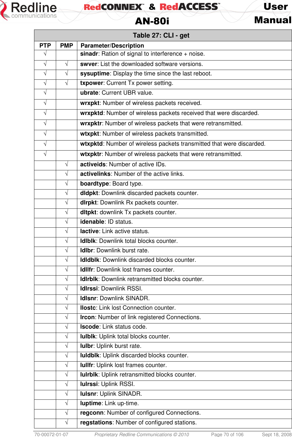
![& User AN-80i Manual 70-00072-01-07 Proprietary Redline Communications © 2010 Page 71 of 106 Sept 18, 2008 Table 27: CLI - get PTP PMP Parameter/Description √ uldpkt: Uplink discarded packets counter. √ ulrpkt: Uplink Rx packets counter. √ ultpkt: Uplink Tx packets counter. √ werxpkt: Wireless Eth Rx packets counter. √ werxpktdis: Wireless Eth Rx discarded packets counter. √ werxpkterr: Wireless Eth Rx packets with errors counter. √ wetxpkt: Wireless Eth Tx packets counter. √ wetxpktdis: Wireless Eth Tx discarded packets counter. √ wetxpkterr: Wireless Eth Tx packets with errors counter. 5.3.8 Load Use the load command to load an ID table from non-volatile memory. Table 28: CLI - load PTP PMP Parameter/Description √ load idtable - Load all IDs from flash memory. √ load file <server> <name> <mode> Load saved security keys information from file on FTP server. <server> IP address of the TFTP server. Files must be stored in the TFTP server default download directory. <name> File name on server. File name must be one of the following: dsa_key_<mac>.pem DSA key used for SSH. rsa_key_<mac>.pem RSA Key used for SSH. ssl_cert_<mac>.pem SSL Certificate. ssl_key_<mac>.pem SSL Key. usr_wcert_<mac>.der User wireless certificate. usr_wkey_<mac>.der User wireless key. usr_wacert_<mac>.der User wireless authority certificate. Where, <mac> is the MAC address of the board. For example: dsa_key_00-09-02-00-01-02.pem <mode> Defaults to 'usr' if mode is not specified. run - Display keys currently in-use. usr - Display the user-specified keys and certificates. √ √ load script<server> <name> Use the script command to load the AN-80i configuration information from a file (created using script command) from a remote TFTP server. The file must be located in the TFTP default directory. <server> - [server IP address] <name> - [script file name]](https://usermanual.wiki/Redline-Communications/AN80IE.user-manual/User-Guide-1282965-Page-71.png)
![& User AN-80i Manual 70-00072-01-07 Proprietary Redline Communications © 2010 Page 72 of 106 Sept 18, 2008 5.3.9 Logout Use the logout command to terminate the current Telnet session. Table 29: CLI - logout PTP PMP Parameter/Description √ new Terminate the current Telnet session. 5.3.10 New Use the new command to create a new link, group, or connector ID. Table 30: CLI - new PTP PMP Parameter/Description √ new <id_type> - [link | group | conn] <id> - <id number> 5.3.11 Ping Use the ping command to initiate an ICMP ping command from the AN-80i. Table 31: CLI - ping PTP PMP Parameter/Description √ ping <address> - Target IP address <count> - Number of ICMP packets to send [1..16]. 5.3.12 Reboot Use the reboot command to reboot the AN-80i. Table 32: CLI - reboot PTP PMP Parameter/Description √ √ reboot <seconds> Time to reboot the AN-80i. <seconds> Time in seconds (0 cancels previous reboot command). 5.3.13 Reset Use the reset command to set all AN-80i statistics values to zero. Table 33: CLI - reset PTP PMP Parameter/Description √ √ stats: Reset the AN-80i statistics counters. reset stats <Enter>](https://usermanual.wiki/Redline-Communications/AN80IE.user-manual/User-Guide-1282965-Page-72.png)
![& User AN-80i Manual 70-00072-01-07 Proprietary Redline Communications © 2010 Page 73 of 106 Sept 18, 2008 5.3.14 Save Use the save command to copy edited parameter settings into non-volatile memory. save [option] <Enter> Table 34: CLI - save PTP PMP Parameter/Description √ √ config: Save Ethernet, wireless, and user configuration settings. snmp: Save SNMP settings. defaultconfig: Overwrite parameters with the factory default settings. The following settings are not affected: system name, location, details and contact, frequency list, SNMP configuration, IDs table (PMP only). 5.3.15 Script Use the script command to save a file containing a string of CLI commands that can be used to restore the current (active) configuration of the AN-80i. Saved configuration files can be viewed, copied, and/or modified using a text editor. The file will be saved in the TFTP default directory. The filename may be any name and extension valid for the TFTP server platform. It is recommended use a filename that uniquely identifies the An-80i unit and the current date (e.g., Red80-AD0023-080723.cfg). See also 'loadscript' command. Table 35: CLI - script PTP PMP Parameter/Description √ √ script <server> - [TFTP server IP address] <name> - [script file name] 5.3.16 Set Use the set command to view and/or change a parameter. View a parameter: set [field] <Enter> Change a parameter: set [field] [value] <Enter> Table 36: CLI - set PTP PMP Parameter/Description √ activekey: Current active options key. <active_idx> - [ 0 | 1] √ adaptmod: Enable or disable the adaptive modulation function. off - Disable on - Enable When enabled, the AN-80i will automatically change the modulation to the highest setting that can sustain a packet error rate lower than 1x10e-6. If the packet error rate exceeds 1x10e-6, the system automatically steps down modulation/code rate (i.e., from 16 QAM 3/4 to 16 QAM 1/2 ) to maintain the wireless link quality.](https://usermanual.wiki/Redline-Communications/AN80IE.user-manual/User-Guide-1282965-Page-73.png)
![& User AN-80i Manual 70-00072-01-07 Proprietary Redline Communications © 2010 Page 74 of 106 Sept 18, 2008 Table 36: CLI - set PTP PMP Parameter/Description √ antgain: Enter value for antenna gain (dBi). When DFS is enabled, it is important that the Antenna Gain setting matches the true antenna gain. If the antenna gain is set higher incorrectly, the AN-80i is less sensitive to detecting interference, and is not operating in compliance with the UK/ETSI standard. √ atpc: Enable or disable the ATPC function. Both AN-80i units monitor Rx signal and automatically adjust the Tx level of the transmitting system to optimize system performance. The ATPC feature must be enabled on both ends of the link. off - Disable on - Enable This mode can be changed only if allowed by the options key. If the options key does not allow changes: 1) value is specified by the options key, 2) executing a set command for this field will generate an error message. √ √ autoscan: Enable or disable the Autoscan function. off - Disable on - Enable When enabled, the PTP Subscriber (system mode) AN-80i automatically scans available channels to locate the current operating frequency of the PTP Sector Controller system. Executing a set command this field on a PTP Sector Controller will generate an error message. √ bsporten: Sector controller Ethernet port enable. <id> - [id number] <mode> - <on/off> √ √ buzzer: Enable or disable the audible alignment buzzer. off - Disable on - Enable When enabled, the rate of the tone is proportional to the receive signal strength (faster = stronger signal). √ √ chwidth: Enter the channel bandwidth in MHz. Valid entries are 10, 20, and 40. √ congid: Connection's group ID. <id> - [id number] <gid> - <gid> √ conlid: Connection's Link ID. <id> - [id number] <lid> - <lid> √ conpri: Connection priority. <id> - [id number] <pri> - <VLAN priority> √ convid: Connection VLAN ID. <id> - [id number] <vid> - <VLAN ID> √ conviden: Connection VLAN enable. <id> - [id number] <mode> - <on/off>](https://usermanual.wiki/Redline-Communications/AN80IE.user-manual/User-Guide-1282965-Page-74.png)
![& User AN-80i Manual 70-00072-01-07 Proprietary Redline Communications © 2010 Page 75 of 106 Sept 18, 2008 Table 36: CLI - set PTP PMP Parameter/Description √ dfsaction: Select the mode of operation for DFS. The system set to master-mode monitors for interference from radar devices and other equipment using the same channel frequency. When interference is detected, the system automatically takes the action selected using the drop-down menu: <action> - [none=0 | txoff=1 | chgfreq=2] None: The DFS function is disabled. Tx Off: Transmission is immediately disabled when radar signals are detected. This action is recorded in the message log and an SNMP trap message is sent (if SNMP enabled). Chg Freq: Relocate transmission to an alternative frequency immediately when radar signals are detected. This action is recorded in the message log and a trap message is sent (if SNMP enabled). √ dlqos: Downlink QoS. <id> - [id number] <qos> - <QoS> √ dlrate: Downlink rate. <id> - [id number] <rate> - <rate> √ dst: Enter the actual length of the path that the wave travels in order to establish the link. Units are defined by dstmu setting. This value is used to calculate the transmission-to-response interval and disregard reflections of the transmitted signal. Used only if dstmod is set to 'manual'. √ dstmode: Select the mode for determining the distance of the wireless link. auto: Distance is calculated automatically by the AN-80i. manual: Operator enters link distance. √ dstmu: Select the measurement unit for the link length (dstmode). mile - dstmode units are miles km - dstmode units are kilometers √ efw: Enable or disable the Ethernet Follows Wireless function. off - Disable on - Enable When Ethernet Follows Wireless is enabled the Ethernet port status is controlled to reflect the status of the wireless interface. When the AN-80i detects that the wireless interface has failed (or is manually disabled), the local Ethernet port is immediately disabled. The Ethernet port is enabled when the AN-80i registers on the wireless link. √ efwtimeout: Enter the period (in seconds) the Ethernet port will remain disabled following loss of connectivity on the wireless interface. Following this interval, the Ethernet port will be automatically re-enabled to allow management of the AN-80i. √ encmode: Enable or disable the encryption function. off - Disable on - Enable If encryption is enabled, the correct encryption keys must be entered on both communicating systems.](https://usermanual.wiki/Redline-Communications/AN80IE.user-manual/User-Guide-1282965-Page-75.png)
![& User AN-80i Manual 70-00072-01-07 Proprietary Redline Communications © 2010 Page 76 of 106 Sept 18, 2008 Table 36: CLI - set PTP PMP Parameter/Description √ enckey: Enter the encryption key. If encryption is enabled, the correct encryption keys must be entered on both communicating systems. Used only if encmode is set to 'on'. <mac> - <MAC address> √ √ ethmode: Enter the Ethernet speed and duplex setting. auto - Auto-negotiate 10hd - 10Base-T Half Duplex 10fd - 10Base-T Full Duplex 10hd - 100Base-T Half Duplex 100fd - 100Base-T Full Duplex √ exit: Exit from the current mode (go up one level). √ √ flowctrl: Enable or disable the flow control function. The Flow control feature enables the AN-80i to request other Ethernet devices to pause transmission during busy periods. off - Disable on - Enable √ √ gateway: Enter the IP address of the default gateway on this segment. √ √ gmt: Enter the time offset from GMT (i.e., -5 for EST). √ grppri: Group priority. <id> - [id number] <pri> - <VLAN priority> √ grpqos: Group QoS. <id> - [id number] <qos> - <QoS> √ grprate: Group rate. <id> - [id number] <rate> - <group rate> √ grpvid: Group VLAN ID. <id> - [id number] <vid> - <VLAN ID> √ grpviden: Group VLAN enable. <id> - [id number] <mode> - <on/off> √ √ http: Enable or disable the HTTP function. When disabled, the Web interface will not be available. off - Disable on - Enable √ idname: ID name. <id> - [id number] <name> - <id name> - maximum 15 characters √ lkname: Link name. <name> - <id name> - maximum 15 characters √ √ ipaddr: Enter the IP address and subnet mask of the AN-80i. Address - IP Address Mask - Subnet Mask Yes - Confirmation to proceed](https://usermanual.wiki/Redline-Communications/AN80IE.user-manual/User-Guide-1282965-Page-76.png)
![& User AN-80i Manual 70-00072-01-07 Proprietary Redline Communications © 2010 Page 77 of 106 Sept 18, 2008 Table 36: CLI - set PTP PMP Parameter/Description √ maxdst: Maximum distance to a subscriber [Km]. <distance> - Maximum distance from SC to SS [Km]. √ √ maxtxpower: Enter the Tx power level (dBm). This setting is for the transceiver output only. The actual EIRP depends on the gain of the connected antenna. See section 7: Appendices for a list the maximum transmit power setting based on the antenna gain for a series of frequency settings. The maximum value for this field is determined by the options key. √ mgmtag: Management VLAN enable. <mode> - [on | off] √ mgmvid: Management VLAN ID. <vlan_id> - <VLAN ID> √ mrate: Enter the maximum uncoded burst rate (Mbps). Entry values are dependant on the channel bandwidth (chwidth). 10 MHz: 3, 4.5, 6, 9, 12, 18, 24 or 27 20 MHz: 6, 12, 18, 24, 30, 36, 48, or 54 40 MHz: 12, 24, 36, 48, 60, 72, 96, or 108 The maximum value for this field is determined by the options key. √ √ netmask: Enter the IP netmask. √ √ noisethreshold: Enter the maximum noise threshold (-104 dBm to -65 dBm). If the measured noise (or interference) level exceeds this threshold, the equipment stops transmitting until the noise level is lower than this threshold. √ √ optionskey: Enter the options key string. <kIdx> - Index of the options key [0 | 1] <kStr> - [<options_key_string>] √ peermac: Peer MAC address. <id> - [id number] <mac> - <MAC address> √ pllm: Enable or disable prioritized low latency mode; off - Disable on - Enable √ √ radio: Enable or disable the radio transmitter. off - Disable on - Enable √ ratedif: Enter the number of modulation levels to step down during re-transmission of errored wireless packets. The level can be set from 0 to 7 (recommended value = 2). √ regper: Frames number between registrations. <frames> - The number of frames between registrations [4..100]. √ √ rffreq: Enter the center frequency for the RF channel. When operating multiple links in close proximity, channel frequencies should be separated by a minimum of the channel size to minimize interference. For example, when operating in with 20 MHz channels, the separation must be greater than 20 MHz. √ √ snmp: SNMP enable setting. off - Disable the SNMP agent. on - Enable the SNMP agent.](https://usermanual.wiki/Redline-Communications/AN80IE.user-manual/User-Guide-1282965-Page-77.png)
![& User AN-80i Manual 70-00072-01-07 Proprietary Redline Communications © 2010 Page 78 of 106 Sept 18, 2008 Table 36: CLI - set PTP PMP Parameter/Description √ √ snmptraplink: Enable or disable sending an SNMP trap message for each link-up and link-down event. <setting> - [on | off] √ snmptraps: Status of the SNMP traps flag. <mode> - [on | off] √ snmptraps: Enable or disable sending all SNMP traps. <setting> - [on | off] √ √ sntp: SNTP enable setting. off - Disable SNTP protocol support. on - Enable SNTP protocol support. √ √ sntpip: Enter the SNTP server IP address. Valid only if sntp is enabled. √ √ sntppoll: Enter the interval to synchronize with the sntp server. <polltime> - SNTP polling interval [hours]. √ sstoss: Status of packet routing between SSs. <id> - [id number] <mode> - <on/off> - Route broadcast packets from SS to SS √ √ syscontact: Enter additional descriptive details about this AN-80i. The description can be any combination of up to 20 letters and numbers. √ √ sysdescr: Enter descriptive details about this AN-80i. The description can be any combination of up to 20 letters and numbers. √ √ sysloc: Enter descriptive details about the location of this AN-80i. The description can be any combination of up to 20 letters and numbers. √ √ syslog: Syslog enable setting. off - Disable syslog server protocol support. on - Enable syslog server protocol support. √ √ syslogip: Enter the syslog server IP address. Valid only if syslog is enabled. √ √ sysmode: PTP Operation: ptpsector controller - The sector controller (base station) begins transmitting automatically; sending poll messages to locate the remote subscribers (ptpsubscriber). ptpsubscriber - Subscriber waits passively, monitoring the selected channel(s) until polled by the ptpsector controller (base station). PMP Operation: pmpsc - The sector controller (base station) begins transmitting automatically; sending poll messages to locate the remote subscribers (pmpss). pmpss - Subscribers wait passively, monitoring the selected channel(s) until polled by the pmpsc (sector controller). <SysMode> - [pmpss | pmpsc] √ √ sysname: Enter the name for this AN-80i. The name can be any combination of up to 20 letters and numbers. √ √ telnet: Enable or disable the Telnet port. If the Telnet port is disabled, it will not be possible to use the CLI interface. off - Disable on - Enable Changes to this field are effective only following reboot.](https://usermanual.wiki/Redline-Communications/AN80IE.user-manual/User-Guide-1282965-Page-78.png)
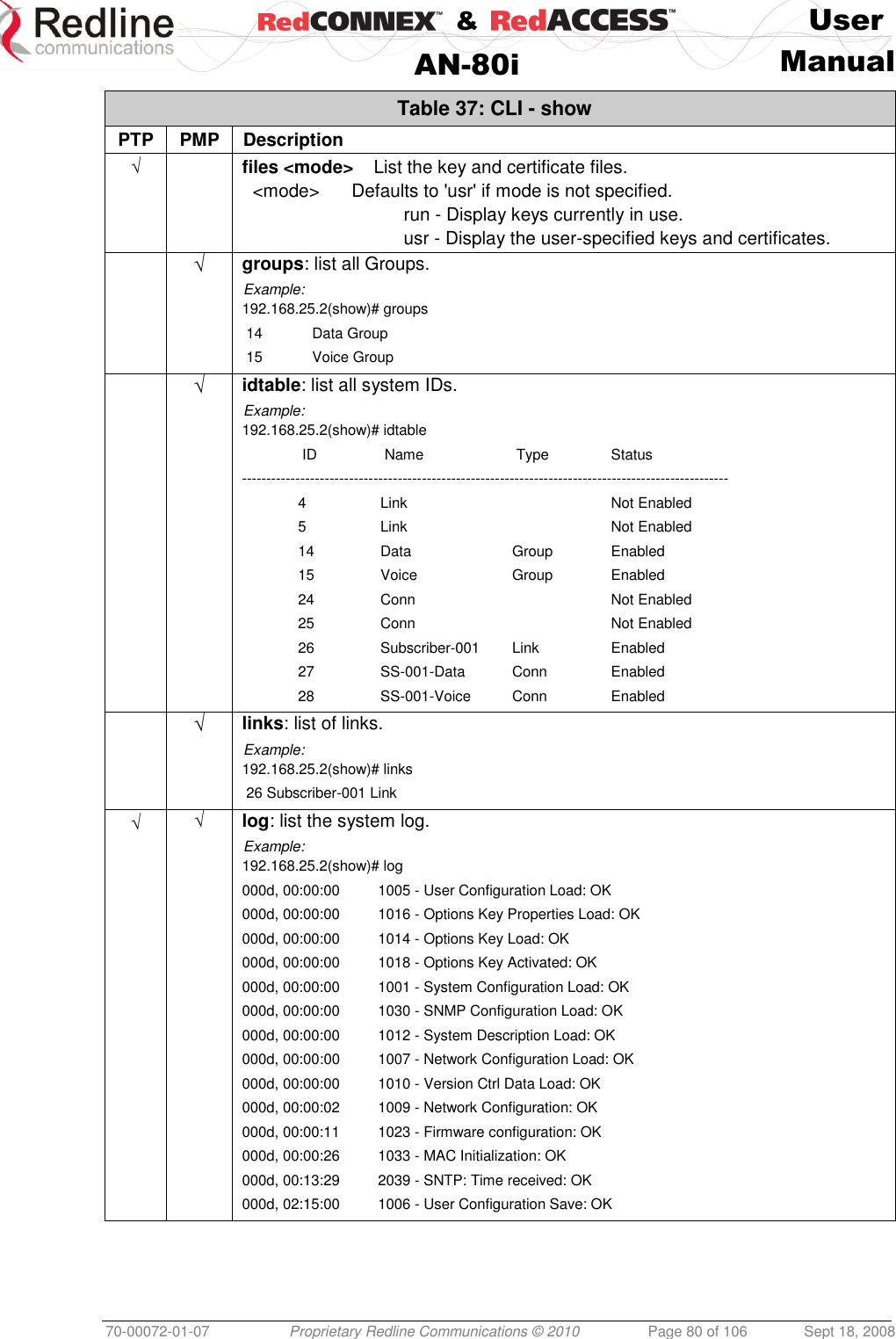
![& User AN-80i Manual 70-00072-01-07 Proprietary Redline Communications © 2010 Page 79 of 106 Sept 18, 2008 Table 36: CLI - set PTP PMP Parameter/Description √ √ telnetport: Enter Telnet port address (default is 23). √ ulqos: Uplink QoS. <id> - [id number] <qos> - <QoS> √ ulrate: Set the uplink rate. <id> - [id number] <rate> - <rate> 5.3.17 Show Use the show command to display system statistics. show <Enter> Change to 'show' mode. show [field] <Enter> Display values for the selected parameter. Table 37: CLI - show PTP PMP Description √ config: list all system configuration information. Example: 192.168.25.2(show)# config System Information: sysname = 1234567890 sysdescr = b sysloc = c syscontact = d telnetport = 23 snmp = On snmptraps = On snmptraplink = On mgmtag = Off mgmvid = 0 Ethernet Configuration: ipaddr = 192.168.25.2 netmask = 255.255.255.0 gateway = 192.168.25.1 flowctrl = Off sntp = On sntpip = 192.168.25.1 sntppoll = 24 gmt = +0:00 syslog = Off syslogip = 192.168.25.1 ethmode = auto http = On telnet = On Wireless Configuration: rffreq = 5610.0 autoscan = Off maxtxpower = 15 chwidth = 20 MHz sysmode = pmpsc swver = 10.00.027 (other: 2.00.004) buzzer = On regper = 18 maxdst = 2 radio = Off = 2 radio = Off √ conns: list all Connections. <id> - [id number] Example: 192.168.25.2(show)# conns 14 27 SS-001-Data Conn](https://usermanual.wiki/Redline-Communications/AN80IE.user-manual/User-Guide-1282965-Page-79.png)
![& User AN-80i Manual 70-00072-01-07 Proprietary Redline Communications © 2010 Page 82 of 106 Sept 18, 2008 5.3.18 Snmpcommunity Use the snmpcommunity command to configure SNMP community permissions. Table 38: CLI - snmpcommunity PTP PMP Description √ √ add: add a new snmp community to the snmp community table. The index value is assigned automatically. Up to eight community entries can be entered in the table. snmpcommunity add <name> <string> <Enter> snmpcommunity add <rights> 0 | r | w | rw <Enter> Where. 0 (zero):Deny read and write permission. r: Grant read access permission only. Deny write permission. w: Grant write access permission only. Deny read permission. rw: Grant read and write access permission for this community. default: Set all snmp parameters to factory default settings. snmpcommunity default <idx> <Enter> del: Delete the specified community entry. snmpcommunity del <idx> <Enter> print: List all SNMP communities and associated permissions. snmpcommunity print <Enter> 5.3.19 Snmptrap Use the snmptrap command to configure the SNMP trap message reporting. Table 39: CLI - snmptrap PTP PMP Description √ √ add: add a new snmp trap to the snmp trap table. The index value is assigned automatically. Up to eight settings can be entered. snmptrap add <ipaddr> <port> <community> <Enter> change: Modify the specified snmp setting. snmptrap change <idx> [-p <port>] [-i <ip_add>] [-c <community] <Ent> del: Delete the specified snmp setting. snmptrap del <idx> <Enter> print: List all SNMP trap settings. snmptrap print <Enter> 5.3.20 Test Use the test command to load the current edited (but not permanently saved) configuration settings. Table 40: CLI - test PTP PMP Parameter/Description √ √ config - AN-80i configuration settings test config <Enter>](https://usermanual.wiki/Redline-Communications/AN80IE.user-manual/User-Guide-1282965-Page-82.png)
![& User AN-80i Manual 70-00072-01-07 Proprietary Redline Communications © 2010 Page 83 of 106 Sept 18, 2008 The AN-80i will operate with these settings for a period of five minutes. During the 'test' period, you may click the Save button at any time to save this configuration permanently (also terminating the five minute timer). If the Save button is not selected, the previous saved settings are reloaded. 5.3.21 Upgrade Use the upgrade command to upload a new software binary file to the AN-80i. Table 41: CLI - upgrade PTP PMP Description √ √ ipaddr: Enter the IP address of the TFTP server. filename: Enter the name of the binary file to be uploaded to the AN-80i. upgrade <ipaddr> <filename> <Enter> You must specify the TFTP server address and the full name of the binary file (including .bin extension). The AN-80i software binary file must be located in the default directory of the TFTP server. 5.3.22 User Use the user command to manage user accounts, passwords, and user Groups. When in user mode, only the <chgpasswd> field is available, since the user can change only his own password. The other commands are available only for members of the administrator Group. Table 42: CLI - user PTP PMP Description √ √ add: Administrators can use this command to add new user accounts. This option is available only for administrators. user add <username> <usertype> <Enter> chgpasswd: For the user accounts, the chgpasswd command must be executed without the <username> parameter -- user's can change only their own password. user chgpasswd [<username>] <Enter> Administrators can change their own password, or specify a <username> to change the password of the specified user account. user chgpasswd [<username>] <Enter> del: Administrators can use this command to delete user accounts. This option is available only for administrators. user del <username> <Enter> print: Administrators can use this command to display a list of user accounts. This option is available only for administrators. user print <Enter> 5.3.23 Whoami Use the whoami command to display the username of the current Telnet session. This command is not available when logged in as administrator. Table 43: CLI - whoami PTP PMP Parameter/Description √ whoami - Display username for this session.](https://usermanual.wiki/Redline-Communications/AN80IE.user-manual/User-Guide-1282965-Page-83.png)