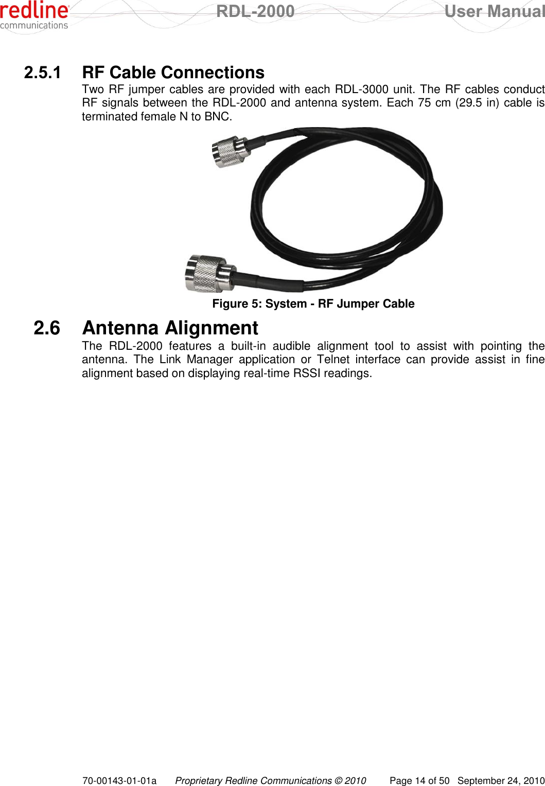
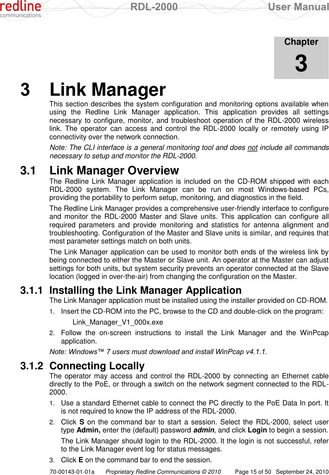
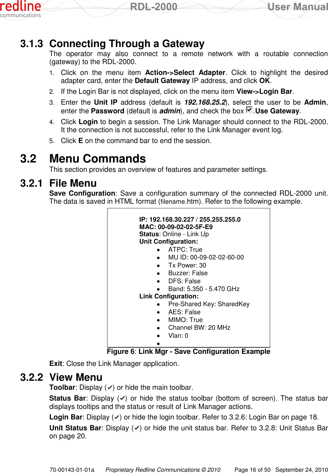
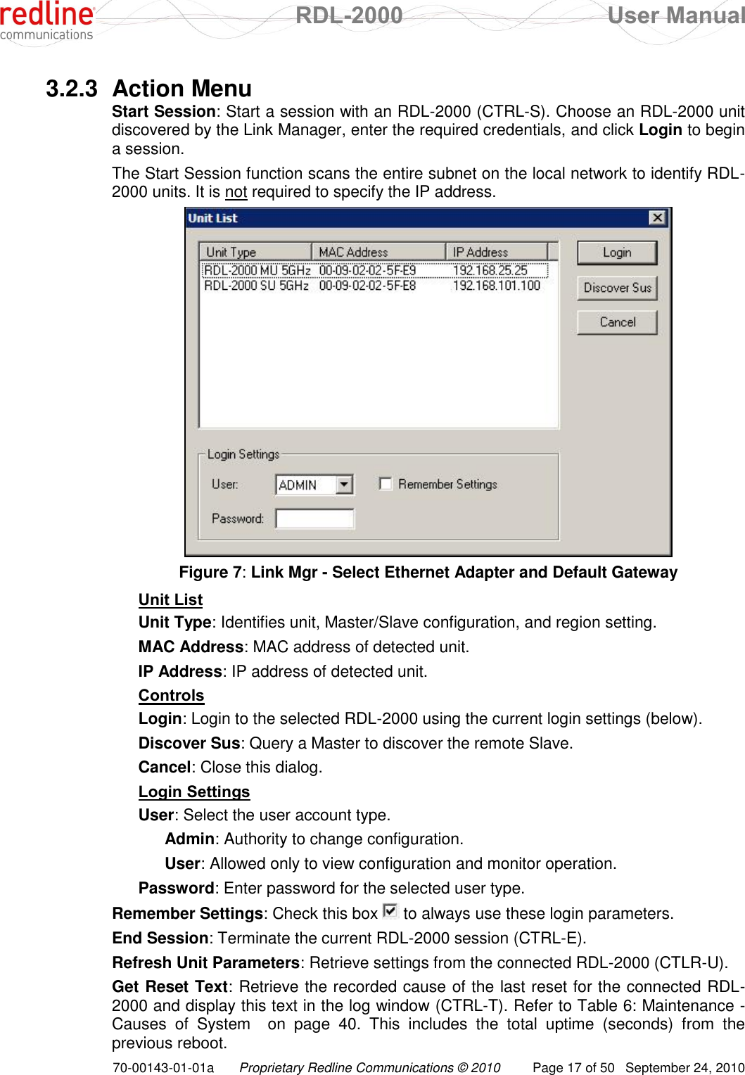
Redline Communications RDL2000 Broadband Wireless Ethernet Bridge User Manual 70 00143 01 01a
Redline Communications Inc. Broadband Wireless Ethernet Bridge 70 00143 01 01a
UserManual.wiki
>
Redline Communications
>
RDL2000 User Manual
>
User Manual
Contents
1.
User Manual
2.
Installation Manual
User Manual
Navigation menu
Upload a User Manual
Namespaces
Wiki Guide
HTML
PDF
Info
Views
User Manual
Discussion / Help
Navigation
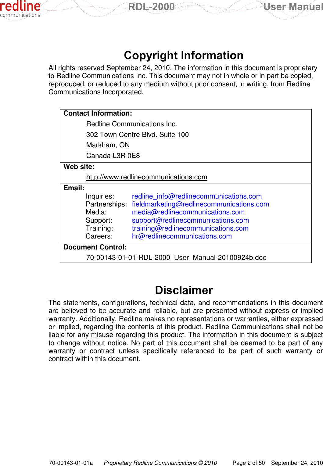
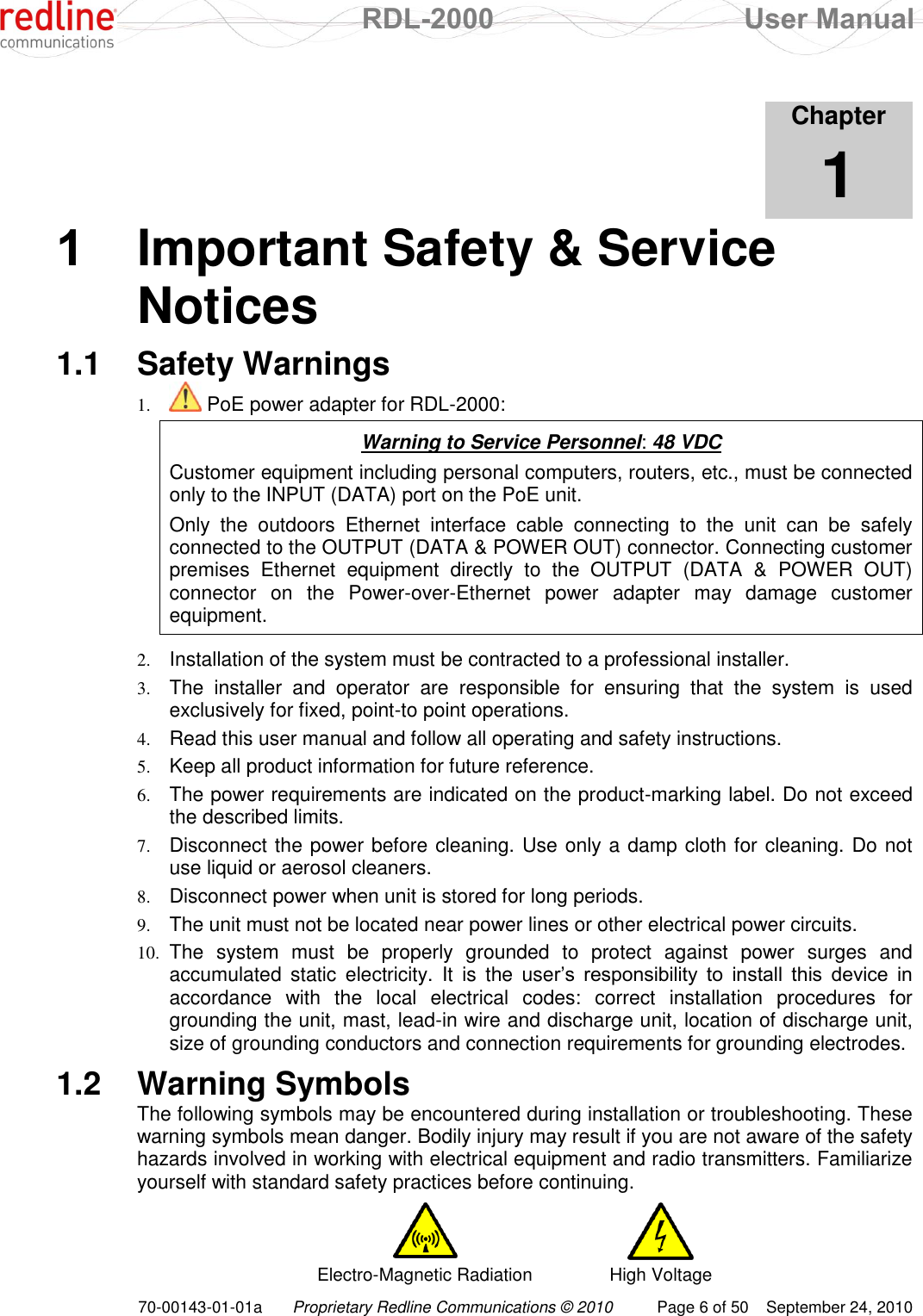
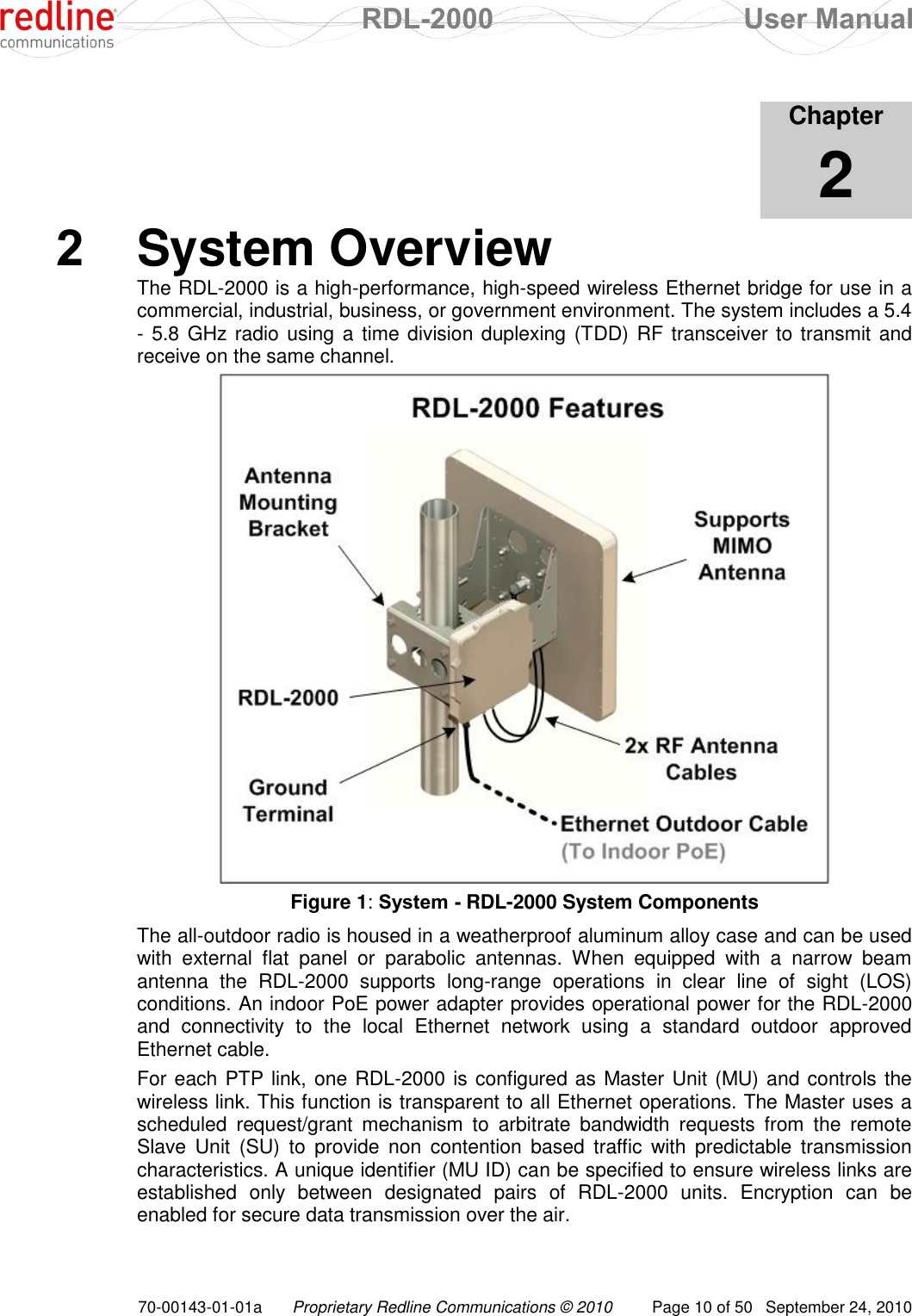
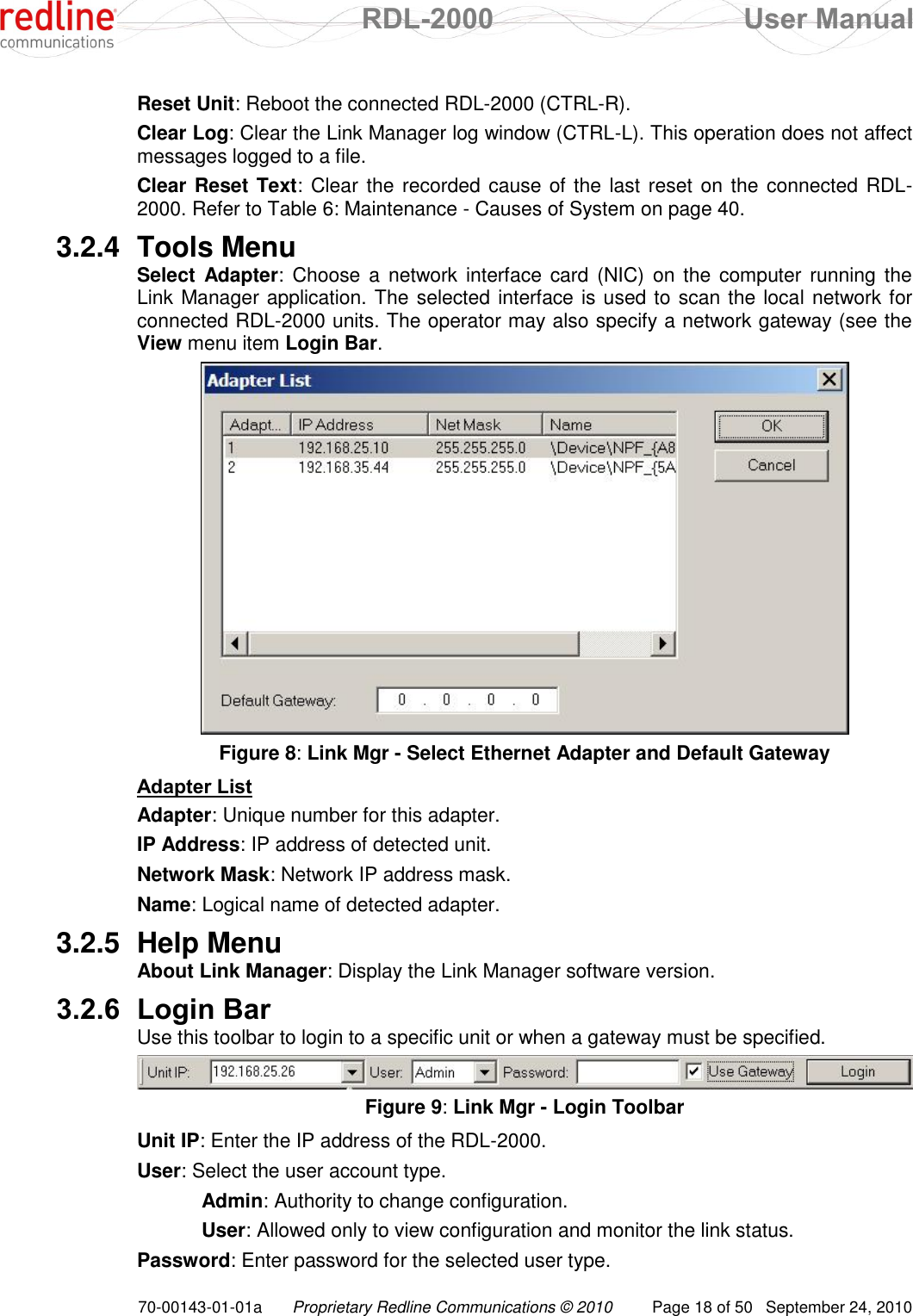
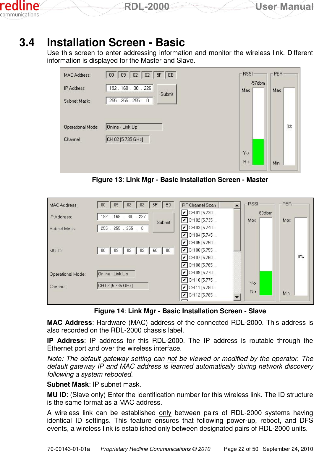
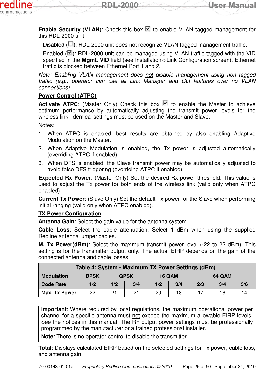
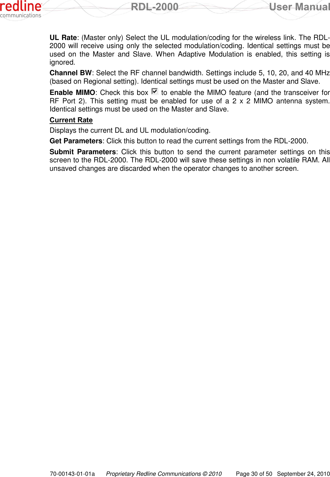
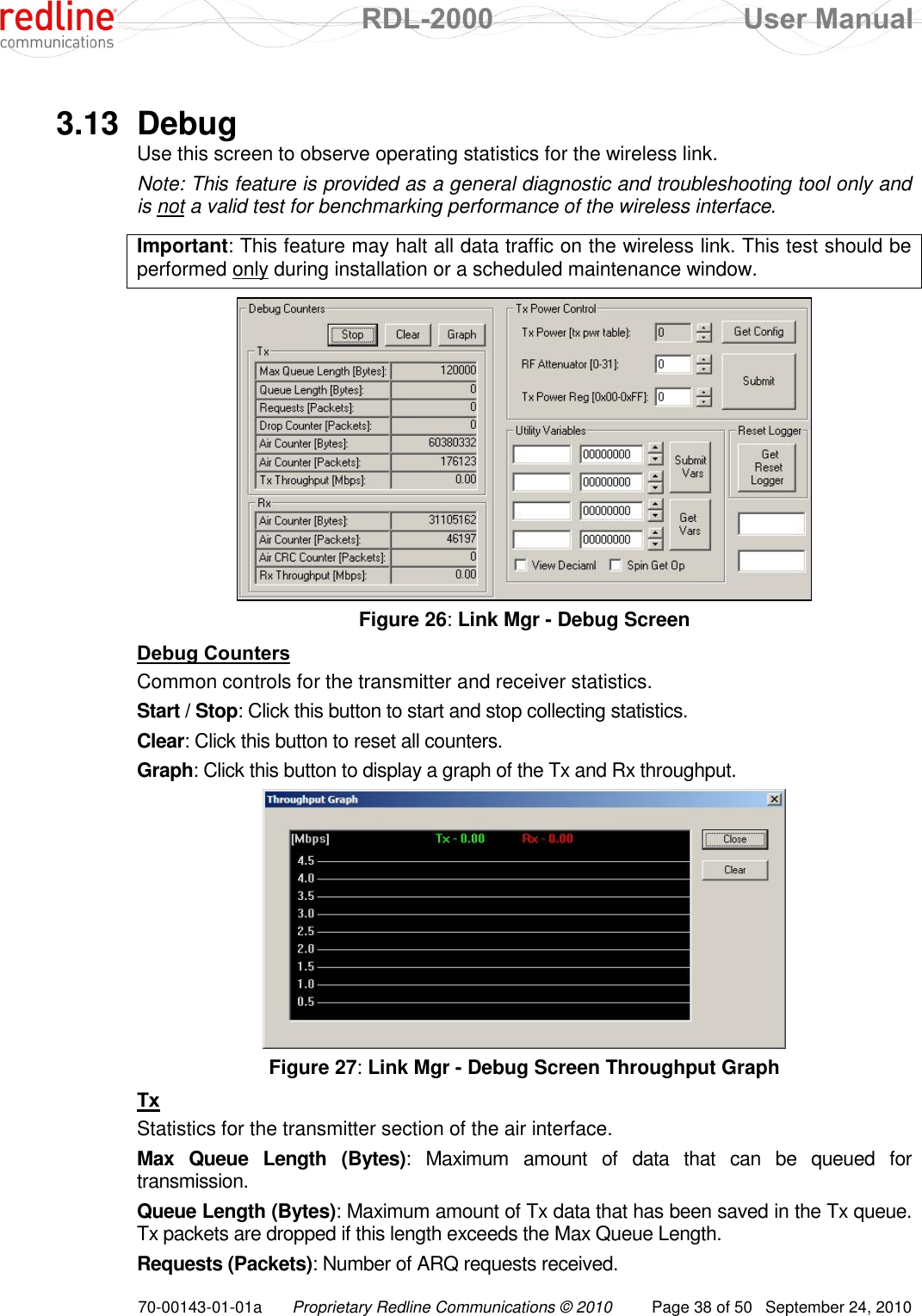
![RDL-2000 User Manual 70-00143-01-01a Proprietary Redline Communications © 2010 Page 42 of 50 September 24, 2010 Chapter 5 5 CLI Interface This section describes the RDL-2000 operations available when using the Command Link Interface (CLI) over a Telnet Connection. All commands are case-sensitive. The user is not required to login for basic access. Note: The CLI does not support all features necessary to configure and operate the RD-2000. Use the Link Manager applications to deploy and monitor the RDL-2000 units. 5.1 CLI Command Summary The following table contains a summary of available CLI commands. Table 8: CLI -Command Summary Master Slave Command Description √ aes Activate/deactivate AES (encryption) √ √ atpc Set ATPC mode and power level √ autorate Activate/deactivate auto rates √ extsync Set/show ext/GPS sync (not supported in this release) √ √ firmware Upgrade firmware √ √ help, ? Show all available commands √ id Set/show id (MAC address format) √ √ ip Set/show IP √ √ logger Activate/deactivate Ethernet logger √ mgmtvid Set/show Mgmt VLAN tag √ √ power Set/show tx power √ √ pwd Set password √ √ quit Exit shell √ rate Set/show peer downlink/uplink rates √ √ reset Reset unit and exit shell √ √ rssi Activate/deactivate RSSI collection √ √ rtext Show last reset text √ set Set/show link peer with this MAC address √ √ sweep Perform spectrum sweep √ √ switchbank Switch firmware banks and reset √ update Program non volatile flash with parameter changes √ √ [user pass] Login to modify parameters](https://usermanual.wiki/Redline-Communications/RDL2000.User-Manual/User-Guide-1349694-Page-42.png)
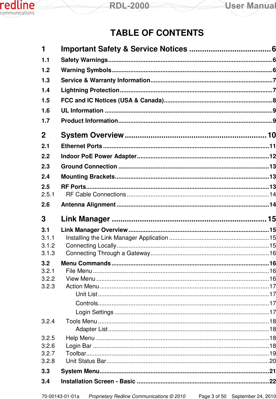
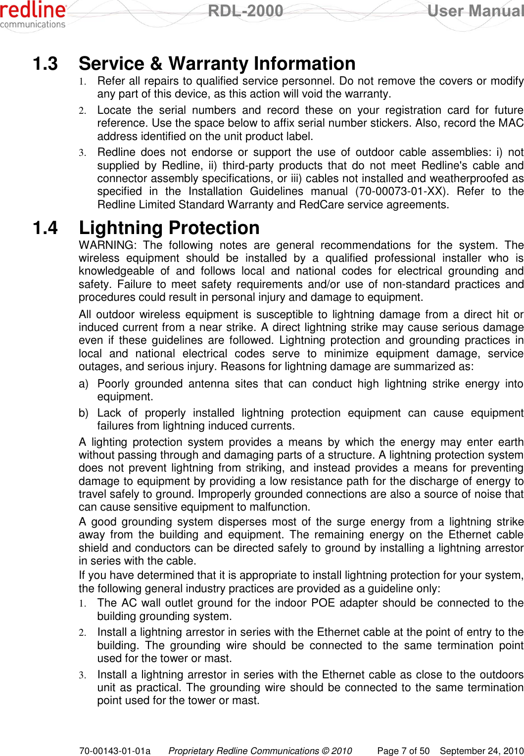
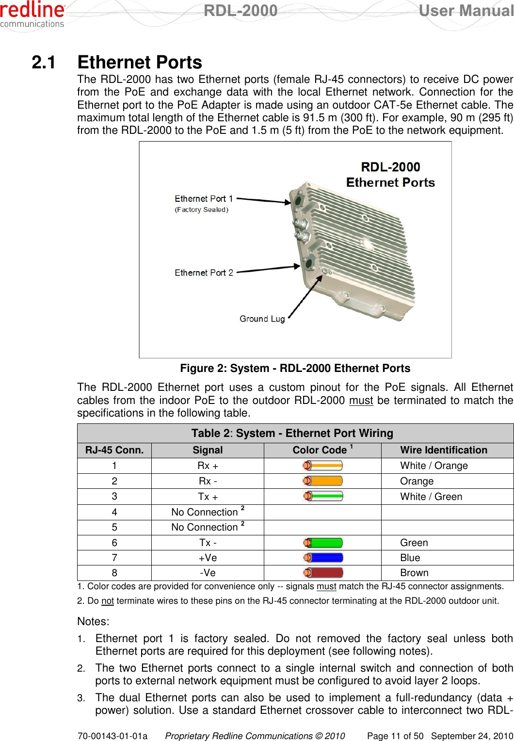
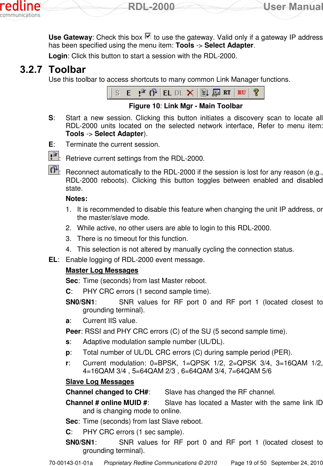
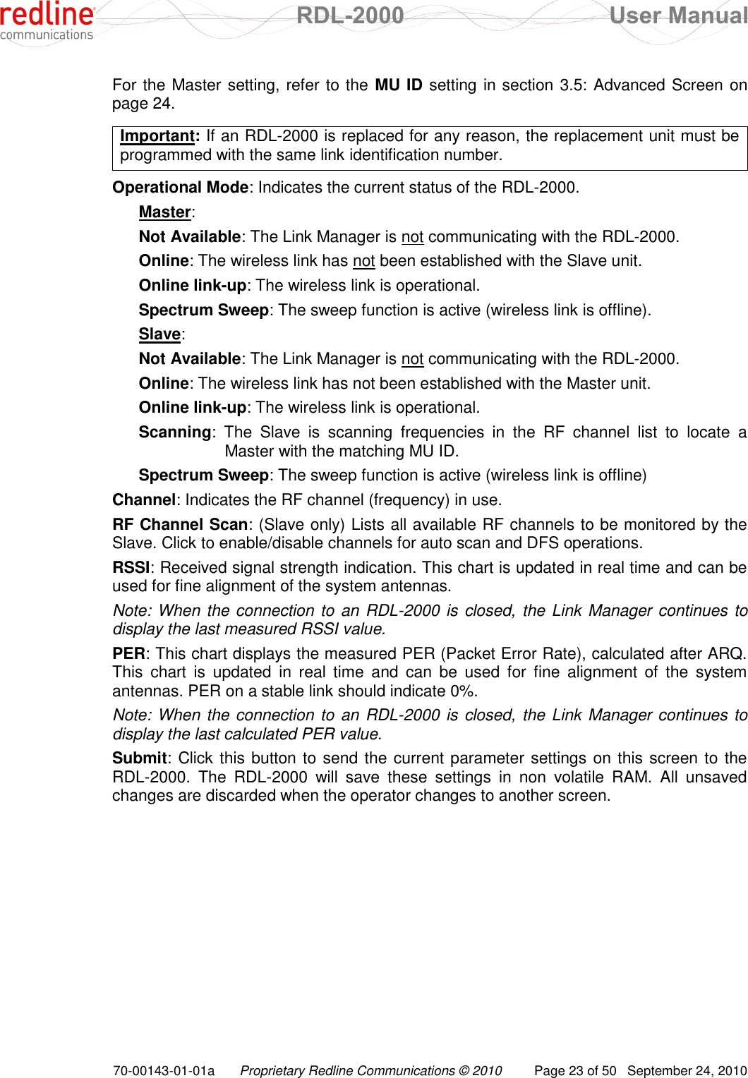
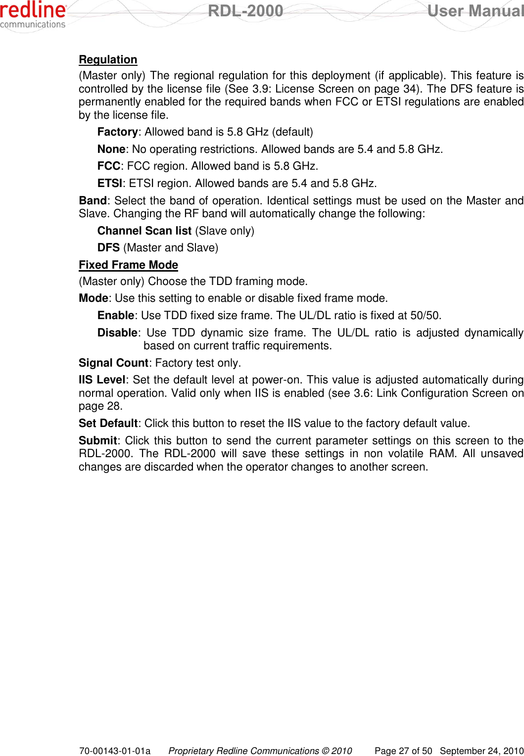
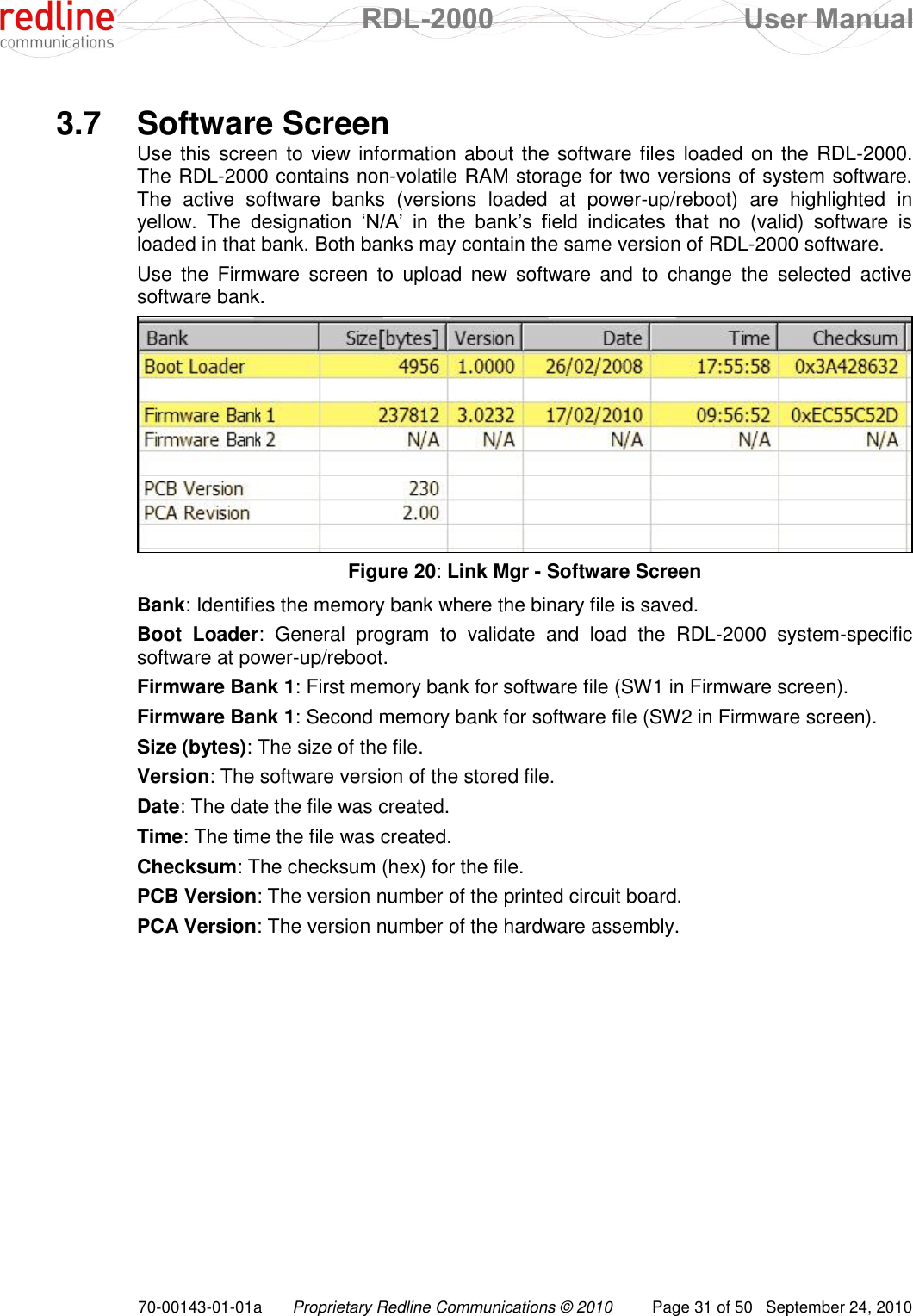
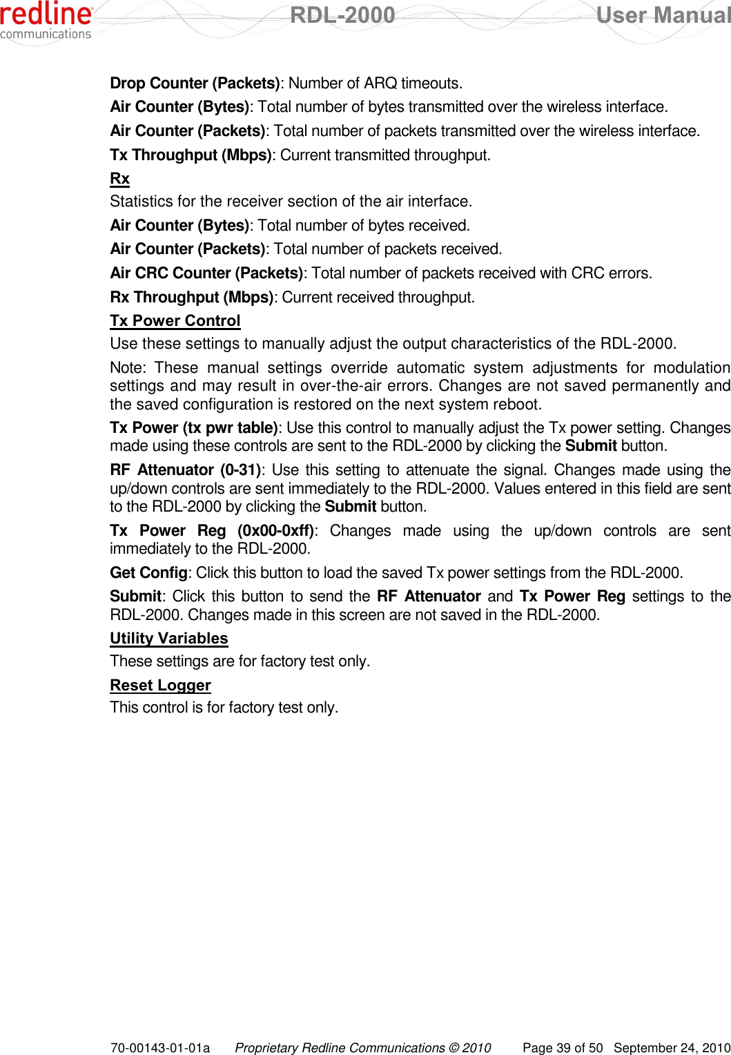
![RDL-2000 User Manual 70-00143-01-01a Proprietary Redline Communications © 2010 Page 43 of 50 September 24, 2010 5.2 Starting a Telnet Session Telnet provides the operator with basic monitoring capabilities from a remote workstation (platform independent). 1. Configure the PC Ethernet adapter (NIC) to be in the same subnet as the RDL-2000. For example, if the RDL-2000 is using the default address 192.168.25.2, set the PC to address to 192.168.25.10. 2. Use an Ethernet cable to connect the PC to the DATA IN port of the PoE power adapter. Important: Do not connect the PC directly to the Ethernet cable from the RDL-2000 -- this may result in damage to the Ethernet interface card in the PC. 3. Power-on the RDL-2000 by connecting AC power to the PoE power adapter. 4. On a PC, open the Run command (Start->Run) and type 'telnet' followed by the IP address of the RDL-2000. telnet 192.168.25.2 [Enter] The system should respond with a prompt similar to the following example: RDL-2000 MU 5GHz 00:09:02:02:5F:FF 192.168.25.2 This prompt provides the following information: Unit type: RDL-2000 Configuration: MU - master, SU - slave RF Frequency: e.g., 5 GHz MAC Address: e.g., 00:09:02:02:5F:FF IP Address: e.g., 192.168.25.2 5.3 Login Procedure The user is not required to login for basic CLI access to view current settings. A login is required to change any parameter setting. The CLI interface is always waiting for the operator to login. Simply type the username and password on a single line and then press Enter. For example, login using the default username and password: [192.168.25.2] >> admin admin [Enter] admin authorized 5.4 Telnet Commands Use the update command to activate and permanently save changes to the RDL-2000 settings. Saving changes to some parameters will automatically reset the RDL-2000. Refer to section 4.2: Reset Causes on page 40. Important: Parameter changes made using CLI commands are effective immediately! Table 9: CLI - Command Summary aes <off> <on> <SharedKey> View or change the AES encryption mode. [blank] - Display current mode/setting. off - Disable AES.](https://usermanual.wiki/Redline-Communications/RDL2000.User-Manual/User-Guide-1349694-Page-43.png)
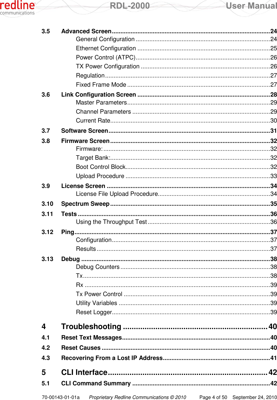
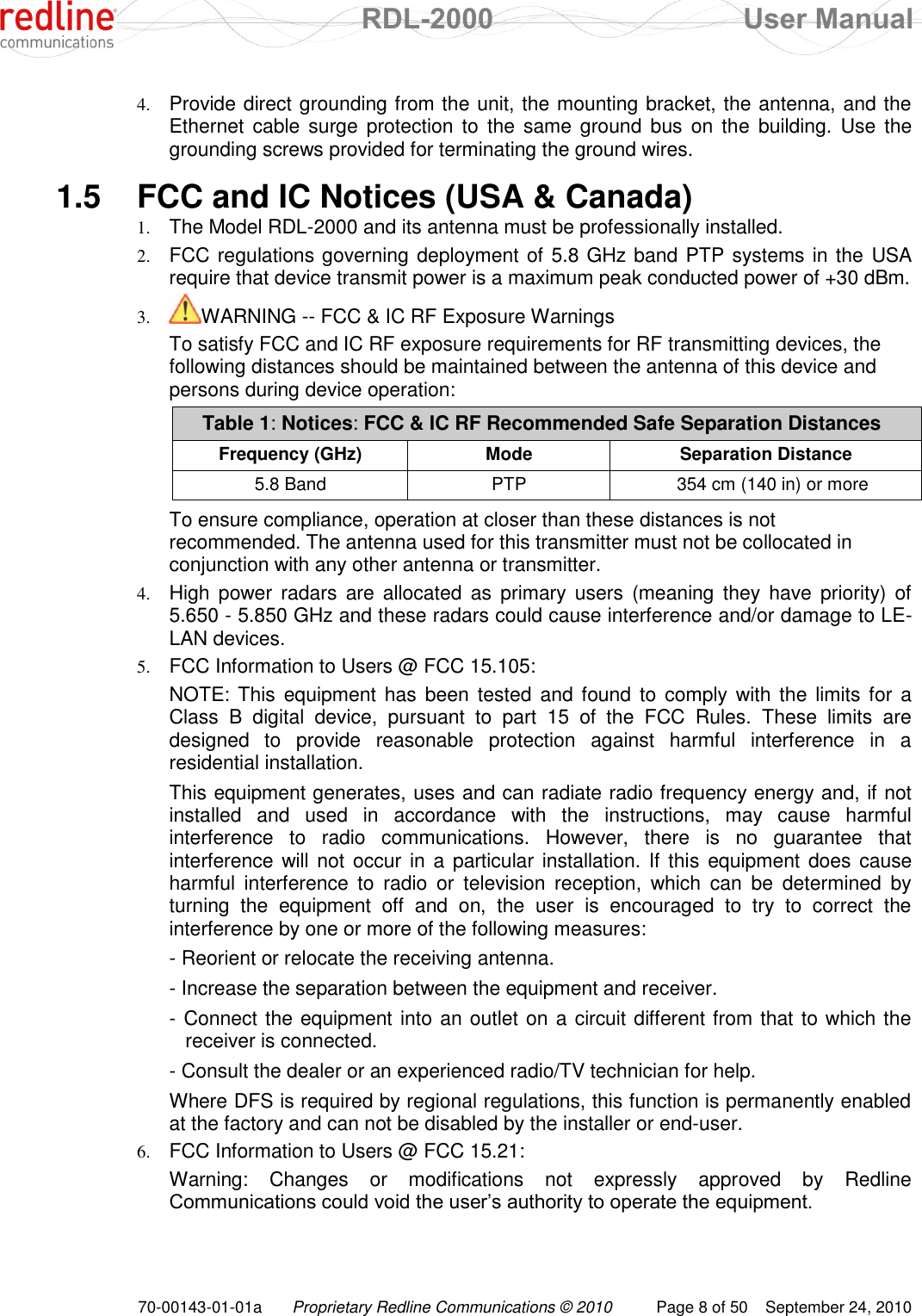
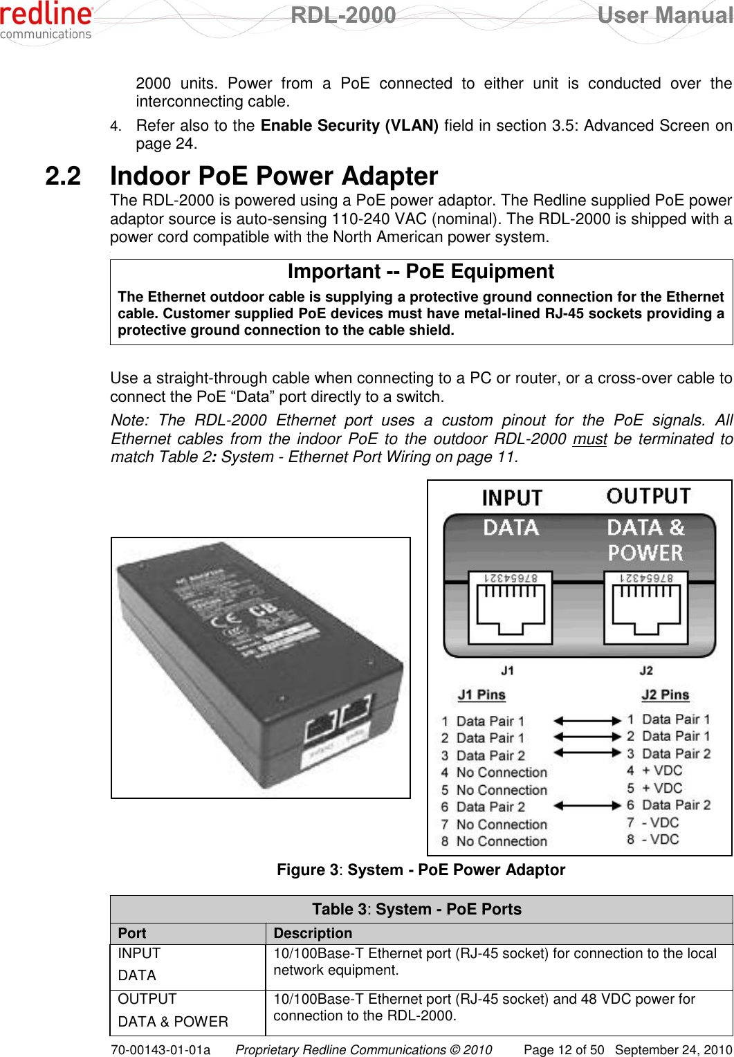
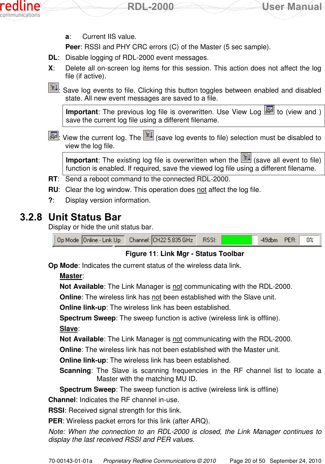
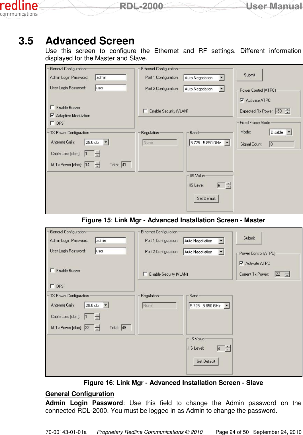
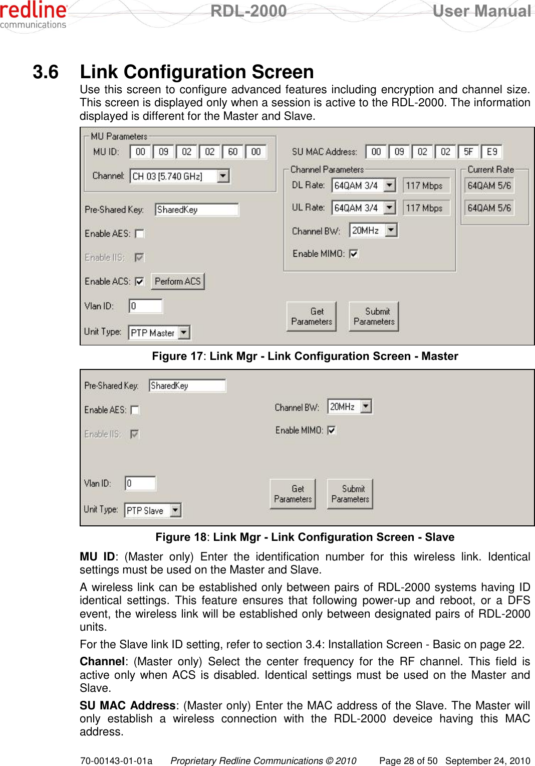
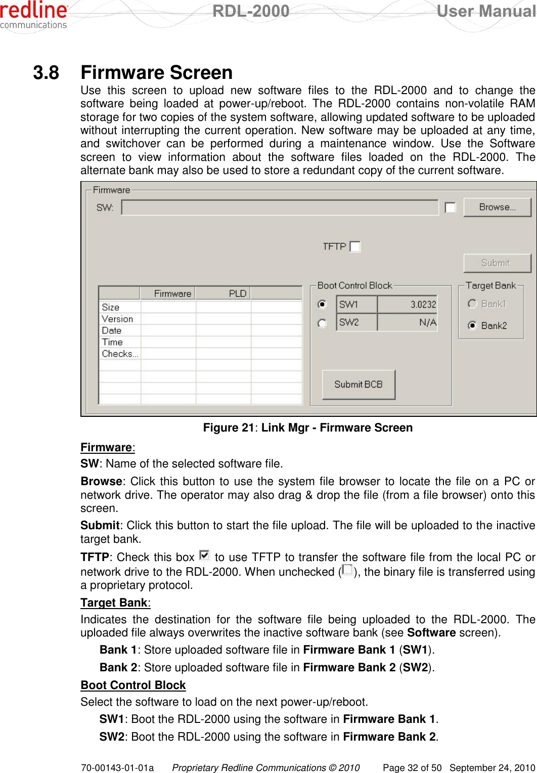
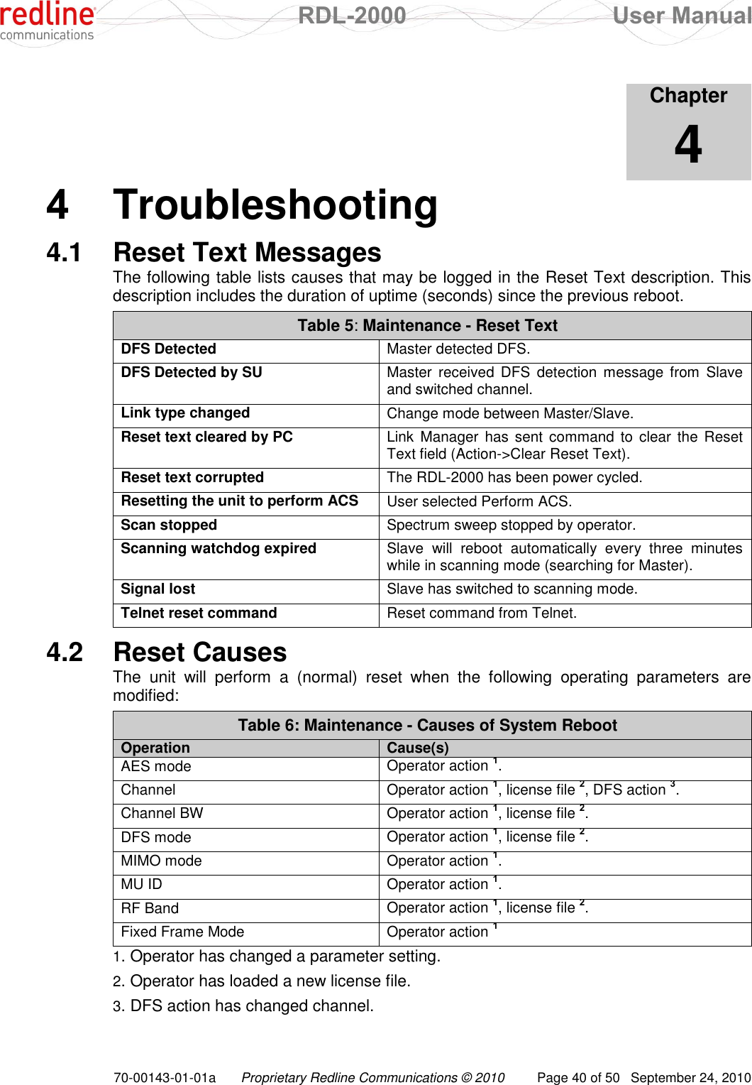
![RDL-2000 User Manual 70-00143-01-01a Proprietary Redline Communications © 2010 Page 44 of 50 September 24, 2010 Table 9: CLI - Command Summary on - Enable AES. SharedKey - View or enter the cryptographic key to be shared between the Master and Slave when AES encryption is enabled. The key must be a maximum of 16 bytes, and include only alphanumeric characters (a-z, 0-9). This field is used only when AES is enabled. Identical encryption settings must be used on the Master and Slave. Example: Use the following command to enable AES on the Master. [192.168.25.2] >>:aes on SharedKey123 aes on SharedKey123 Important: The Master and Slave RDL-2000 units must have identical encryption settings or the system will not establish a wireless link. atpc <off> <on> <power> View or change the automatic transmit power control (ATPC) mode settings. [blank] - Display current mode/setting. Master: Display current ATPC RSSI level. Slave: Display current Tx power level. off - Disable ATPC. on - Enable ATPC. power - Enter the target Rx power threshold (dBm). Example: Use the following command to enable ATPC on the Master and set the RSSI threshold of the link to -60 dBm. [192.168.25.2] >>:atpc on -60 autorate <off> <on> View or change the adaptive modulation settings. When adaptive modulation is disabled, the RDL-2000 will transmit using only using the selected modulation/coding (see rate command). When adaptive modulation is enabled, the modulation/coding is adjusted automatically based on current link conditions. [blank] - Display current mode/setting. off - Disable adaptive modulation. on - Enable adaptive modulation. Example: Enable adaptive modulation on the master: [192.168.25.2] >>:autorate on MU autorate autorate on extsync This function not supported in this release. firmware <[blank] | file.brn> View the firmware versions or upload a new binary file. The RDL-2000 contains non-volatile storage for two versions of the software. The upload function overwrites the non-operational version. [blank] - Display current software versions. The text 'FFFF FFFF' indicates that no software is loaded in the alternate bank. binary - Full name of binary file (including the .bin extension).to upload to the RDL-2000. A TFTP server must be installed and running on the computer running](https://usermanual.wiki/Redline-Communications/RDL2000.User-Manual/User-Guide-1349694-Page-44.png)
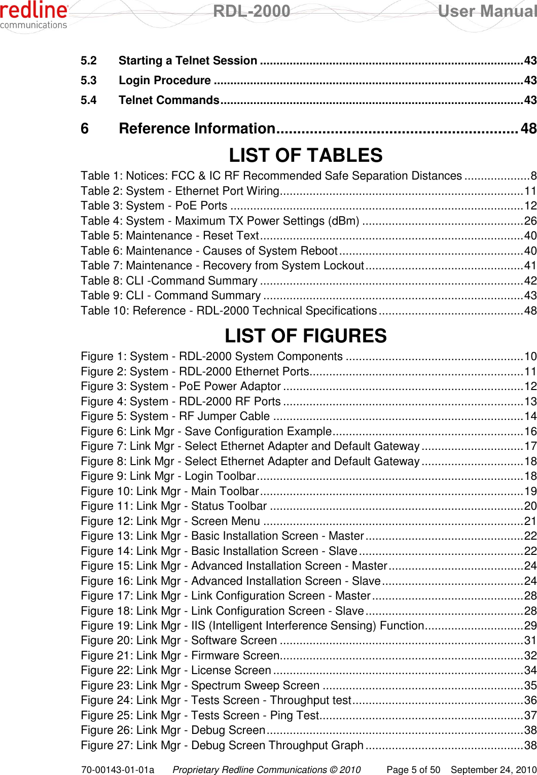
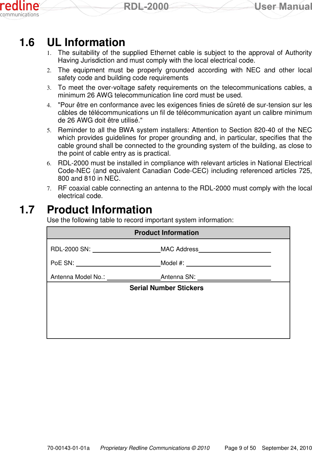
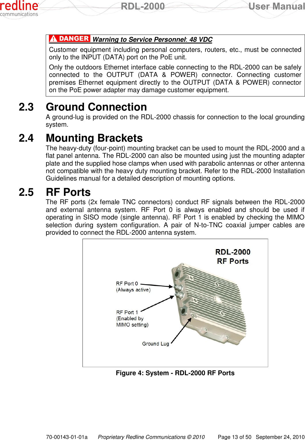
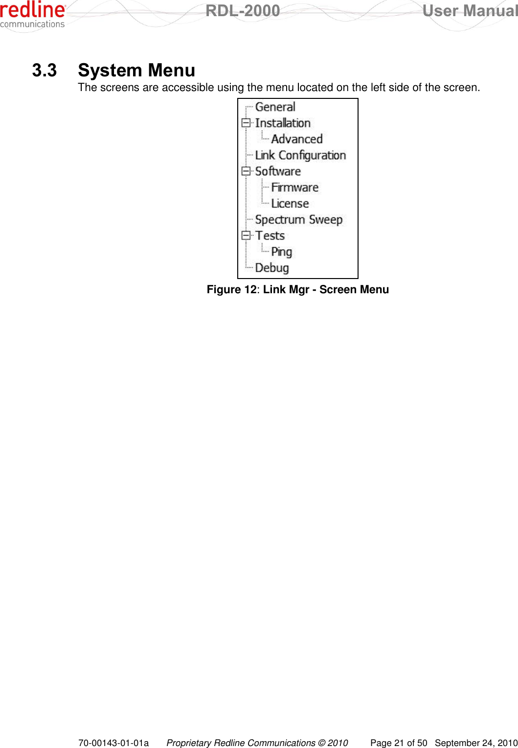
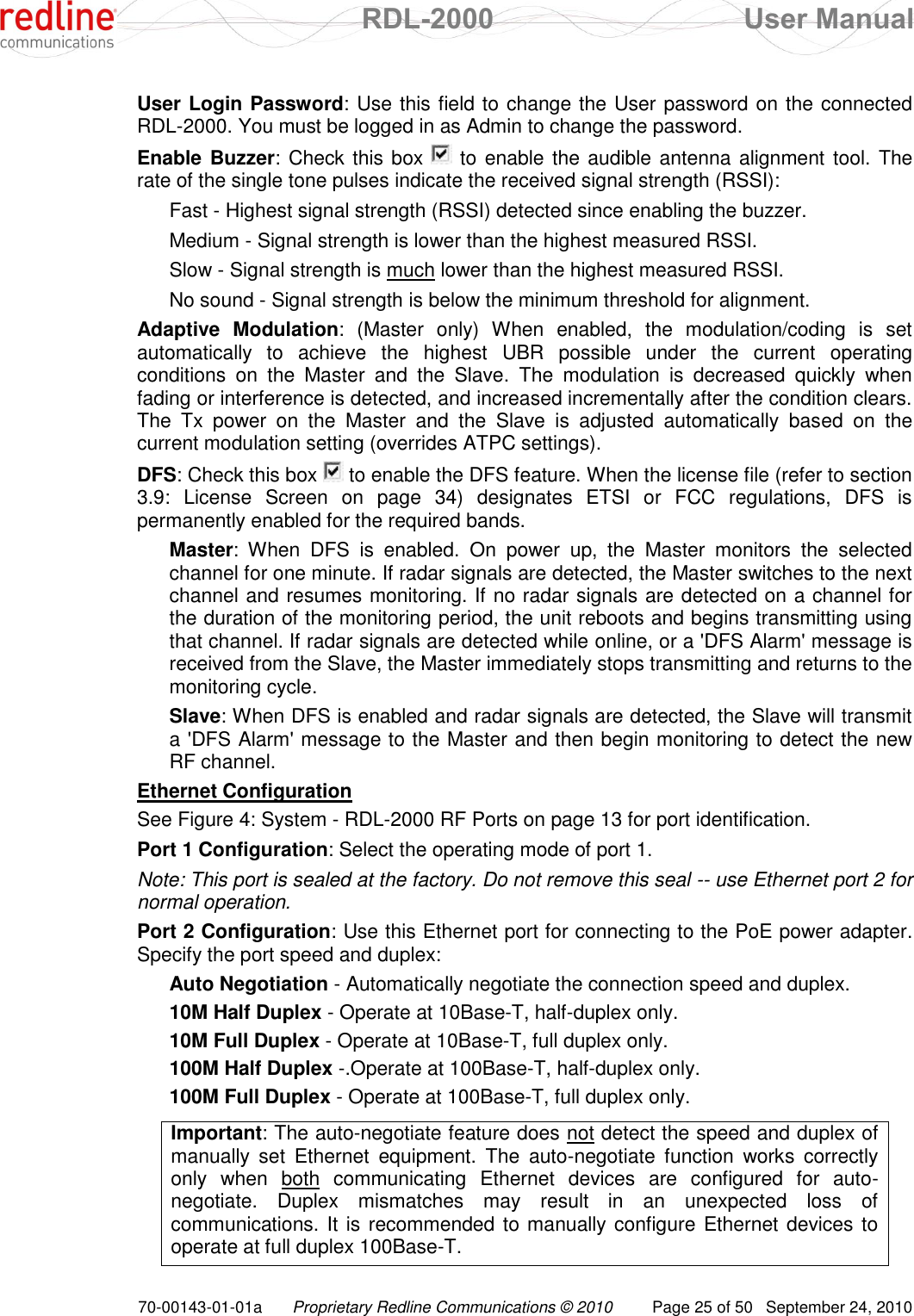
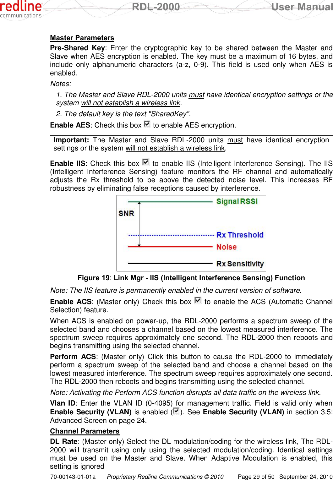
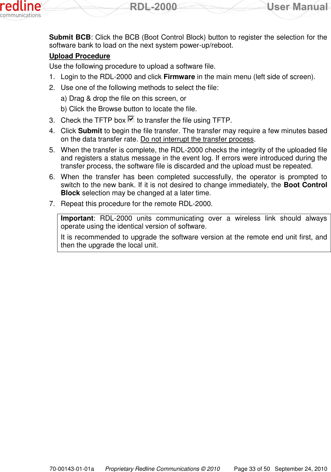
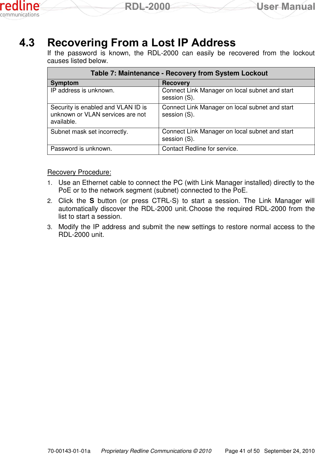
![RDL-2000 User Manual 70-00143-01-01a Proprietary Redline Communications © 2010 Page 45 of 50 September 24, 2010 Table 9: CLI - Command Summary the Telnet session. To upgrade the firmware, the computer hosting the Telnet session must also have a TFTP server. The firmware file must be located in the TFTP servers default directory (can not specify a path). When the transfer has completed successfully, use the switchbanks command to enable the new software version. Example: Upload the software binary file abc.brn to the inactive bank on the RDL-2000: [192.168.25.2] >>: firmware abc.brn id <id_value> View or modify the RDL-2000 Master identifier (MU ID). This identifier ensures the slave established a link only with the designated Master. The identifier is in MAC-address format. [blank] - Display current ID. id_value - Specify the ID for this unit. Example: Set the RDL-2000 ID to 0050c24f7fd2: [192.168.25.2] >>: id 0050c24f7fd2 ip <address> View or modify the RDL-2000 IP address. [blank] - Display current IP address. address - Specify the new IP address for this unit. Example: Set the RDL-2000 IP address to 192.168.20.25: [192.168.25.2] >>: ip 192.168.20.25 logger <off> <on> Change the logger settings. When enabled, the logger feature sends all RDL-2000 event messages directly to the screen running the CLI session. All CLI commands remain available while the logger feature is enabled. off - Disable the logger. on - Enable he logger. Example: Enable the logger: [192.168.25.2] >>: logger on mgmtvid <VID> View or modify the RDL-2000 management VLAN ID setting. When security is enabled, the RDL-2000 can be managed only using VLAN traffic tagged with the value specified in the mgmtvid field. [blank] - Display current VLAN ID. address - Specify the new VLAN ID for this RDL-2000. Example: Set the RDL-2000 VLAN ID to 12: [192.168.25.2] >>: mgmtvid 12 power View the current RDL-2000 TX power output. When automatic controls are enabled, the displayed value may be different than the TX Power setting in the Link Manager Installation->Advanced screen. Example: Display the current Tx power setting: [192.168.25.2] >>: power](https://usermanual.wiki/Redline-Communications/RDL2000.User-Manual/User-Guide-1349694-Page-45.png)
![RDL-2000 User Manual 70-00143-01-01a Proprietary Redline Communications © 2010 Page 46 of 50 September 24, 2010 Table 9: CLI - Command Summary Current power = 15 dBm pwd <new_pswd> <new_pswd> Change the password of the current user (must be logged-in) new_pwd - Enter the new password twice (second entry is for confirmation). Password changes are saved immediately and do not require the update command. Example: Change password to Az123: [192.168.25.2] >>: pwd Az123 Az123 quit Exit from this Telnet session. Important: If required, save parameters before exiting (see update command). All unsaved changes are discarded. Example: Exit from this session: [192.168.25.2] >>: quit Connection to host has been lost. rate <dl_rate> <ul_rate> View or modify the RDL-2000 downlink and uplink rates. Rate settings are: 0 = BPSK 1/2, 1 = QPSK 1/2, 2 = QPSK 3/4, 3 = 16 QAM 1/2, 4 = 16 QAM 3/4, 5 = 64 QAM 2/3, 6 = 64 QAM 3/4, and 7 = 64 QAM 5/6 dl_rate: Enter the desired maximum downlink modulation/coding for the link. When Adaptive Modulation is disabled, the RDL-2000 downlink rate is fixed at this modulation/coding. When Adaptive Modulation is enabled, this setting is ignored. ul_rate: Select the desired maximum uplink modulation/coding for the link. When Adaptive Modulation is disabled, the RDL-2000 uplink rate is fixed at this modulation/coding. When Adaptive Modulation is enabled, this setting is ignored. Example: Set the RDL-2000 rate to downlink = 64 QAM 5/6 and uplink = 64 QAM 2/3: [192.168.25.2] >>: rate 7 5 reset Reboot the RDL-2000. The current Telnet session will be closed. Unsaved changes will be discarded. Example: Reset the RDL-2000: [192.168.25.2] >>: reset Connection to host has been lost. rtext [clear] View or clear the recorded cause of the last system reset. [blank] - Display cause of last reset. clear - Delete the cause of the last reset. Example: Clear the cause of the last reset: [192.168.25.2] >>: rtext clear rssi [clear] View or enable/disable the RSSI collection settings. [blank] - Display current mode/setting.](https://usermanual.wiki/Redline-Communications/RDL2000.User-Manual/User-Guide-1349694-Page-46.png)
![RDL-2000 User Manual 70-00143-01-01a Proprietary Redline Communications © 2010 Page 47 of 50 September 24, 2010 Table 9: CLI - Command Summary off - Disable RSSI. on - Enable RSSI. Example: Read current RSSI value: [192.168.25.2] >>:rssi rssi -59 [dBm] sweep <start | stop> <all | channel(s)> Perform an RF scan for interference. No user data is transmitted over the wireless link while this test is running. A reboot is required to restore normal operation. Start: Begin scanning the selected channels. The wireless link is offline. Stop: Stop scanning channels. Reboot and resume normal operation. all: Scan all available channels channel(s): Enter one or more RF channel frequencies to be scanned. Example: Scan all enabled channels: [192.168.25.2] >>:sweep start all RF Analyzer: CH = #1 rssi = -77 dBm RF Analyzer: CH = #2 rssi = -78 dBm RF Analyzer: CH = #3 rssi = -48 dBm switchbank [soft | pld | both] Switch between the active and inactive banks of the software. A system reboot is required to activate the selected software version. soft or [blank]: Switch the software load. pld: Switch the firmware load (e.g., bootloader). both: Switch the software and firmware load. Example: Switch to the alternate software load and reboot: [192.168.25.2] >>: switchbank update Activate and permanently save (non volatile RAM) all changes to the system parameters. Saving changes to some parameters will automatically reset the RDL-2000. Example: Activate and save all parameter changes: [192.168.25.2] >>: update](https://usermanual.wiki/Redline-Communications/RDL2000.User-Manual/User-Guide-1349694-Page-47.png)