Redline Communications RDL3000 Advanced Broadband Wireless Infrastructure solution User Manual 70 00158 01 DRAFT
Redline Communications Inc. Advanced Broadband Wireless Infrastructure solution 70 00158 01 DRAFT
Contents
- 1. USer Manual
- 2. User Manual
- 3. user manual
USer Manual
70-00158-01-DRAFT Proprietary Redline Communications © 2010 Page 1 of 142 November 25, 2010
RDL-3000
Advanced Broadband Wireless
Infrastructure Solutions
User Manual
RDL-3000 User Manual
70-00158-01-DRAFT Proprietary Redline Communications © 2010 Page 2 of 142 November 25, 2010
Copyright Information
All rights reserved November 25, 2010. The information in this document is proprietary
to Redline Communications Inc. This document may not in whole or in part be copied,
reproduced, or reduced to any medium without prior consent, in writing, from Redline
Communications Incorporated.
Contact Information:
Redline Communications Inc.
302 Town Centre Blvd. Suite 100
Markham, ON
Canada L3R 0E8
Web site:
http://www.redlinecommunications.com
Email: Inquiries: redline_info@redlinecommunications.com
Partnerships: fieldmarketing@redlinecommunications.com
Media: media@redlinecommunications.com
Support: support@redlinecommunications.com
Training: training@redlinecommunications.com
Careers: hr@redlinecommunications.com
Document Control:
70-00158-01-00-RDL-3000_User_Manual-20101125a.doc
Disclaimer
The statements, configurations, technical data, and recommendations in this document
are believed to be accurate and reliable, but are presented without express or implied
warranty. Additionally, Redline makes no representations or warranties, either expressed
or implied, regarding the contents of this product. Redline Communications shall not be
liable for any misuse regarding this product. The information in this document is subject
to change without notice. No part of this document shall be deemed to be part of any
warranty or contract unless specifically referenced to be part of such warranty or
contract within this document.

RDL-3000 User Manual
70-00158-01-DRAFT Proprietary Redline Communications © 2010 Page 3 of 142 November 25, 2010
CONTENTS SUMMARY
1 Important Notices ................................................................. 13
1.1 Service & Safety ............................................................................................... 13
1.2 Regulatory Notices .......................................................................................... 15
2 System Features ................................................................... 17
2.1 General Description ......................................................................................... 17
2.2 Ethernet Port .................................................................................................... 18
2.3 Synchronization I/O Port (PPS) ....................................................................... 18
2.4 GPS Antenna Port (GPS ANTENNA) ............................................................... 18
2.5 RF Ports ............................................................................................................ 18
2.6 Ground Lug ...................................................................................................... 19
2.7 Audible Alignment ........................................................................................... 19
2.8 Management Interfaces ................................................................................... 20
2.9 PoE Power Adapter .......................................................................................... 21
3 Functional Overview ............................................................. 22
3.1 Overview ........................................................................................................... 22
3.2 PMP Mode ......................................................................................................... 23
3.3 PTP Mode ......................................................................................................... 38
4 Web Interface ........................................................................ 39
4.1 Connecting With a Web Browser .................................................................... 39
4.2 System Menu .................................................................................................... 41
4.3 Dashboard Display .......................................................................................... 44
4.4 Status Screens ................................................................................................. 46
4.5 Configuration Screens ..................................................................................... 57
4.6 Provisioning Screens ...................................................................................... 74
4.7 Utilities Screens ............................................................................................... 86
5 CLI Interface .......................................................................... 95
5.1 Telnet Access ................................................................................................... 95
5.2 Command Summary ........................................................................................ 95
5.3 Command Set ................................................................................................... 97
6 Diagnostics & Troubleshooting ......................................... 118
6.1 Interface Connection Issues ......................................................................... 118

RDL-3000 User Manual
70-00158-01-DRAFT Proprietary Redline Communications © 2010 Page 4 of 142 November 25, 2010
6.2 Status Codes .................................................................................................. 119
6.3 Working with System Parameters................................................................. 120
6.4 Factory Default Settings ................................................................................ 121
6.5 Long Reset (Recover from Lost Password or IP) ........................................ 123
7 Security ............................................................................... 126
7.1 Overview ......................................................................................................... 126
7.2 Wireless Authentication ................................................................................ 127
7.3 AES Encryption .............................................................................................. 128
7.4 SSH for Secure CLI ........................................................................................ 129
7.5 HTTPS/SSL for Secure Web .......................................................................... 130
8 Appendices ......................................................................... 132
8.1 Technical Specifications ............................................................................... 132
8.2 Classification: Services and Service Groups .............................................. 134
8.3 Regional Codes .............................................................................................. 138
8.4 FCC & IC Certified Antennas ......................................................................... 140

RDL-3000 User Manual
70-00158-01-DRAFT Proprietary Redline Communications © 2010 Page 5 of 142 November 25, 2010
TABLE OF CONTENTS
1 Important Notices ................................................................. 13
1.1 Service & Safety ............................................................................................... 13
1.1.1 Safety Warnings .............................................................................................. 13
1.1.2 Warning Symbols ............................................................................................ 13
1.1.3 Lightning Protection ........................................................................................ 14
1.1.4 Service & Warranty Information ...................................................................... 14
1.2 Regulatory Notices .......................................................................................... 15
1.2.1 Deployment in USA and Canada: FCC & IC Notices ....................................... 15
1.2.2 UL Information ................................................................................................ 16
2 System Features ................................................................... 17
2.1 General Description ......................................................................................... 17
2.2 Ethernet Port .................................................................................................... 18
2.3 Synchronization I/O Port (PPS) ....................................................................... 18
2.4 GPS Antenna Port (GPS ANTENNA) ............................................................... 18
2.5 RF Ports ............................................................................................................ 18
2.6 Ground Lug ...................................................................................................... 19
2.7 Audible Alignment ........................................................................................... 19
2.8 Management Interfaces ................................................................................... 20
2.8.1 Web Browser (HTTP) ...................................................................................... 20
2.8.2 Telnet (CLI) ..................................................................................................... 20
2.8.3 SNMP ............................................................................................................. 20
2.9 PoE Power Adapter .......................................................................................... 21
3 Functional Overview ............................................................. 22
3.1 Overview ........................................................................................................... 22
3.2 PMP Mode ......................................................................................................... 23
3.2.1 Subscriber Links ............................................................................................. 23
3.2.2 Services and Service Groups .......................................................................... 24
3.2.3 Setting Wireless Rates .................................................................................... 27
3.2.4 Pass through Mode ......................................................................................... 28
3.2.5 Subscriber-to-Subscriber Traffic ...................................................................... 29
3.2.6 VLAN Tagged Management ............................................................................ 30
3.2.7 PMP Configurations ........................................................................................ 31
VLAN Services ............................................................................................. 31
TLS (Transparent LAN Services) ................................................................. 34
Tagged Traffic .............................................................................................. 35
3.3 PTP Mode ......................................................................................................... 38
4 Web Interface ........................................................................ 39

RDL-3000 User Manual
70-00158-01-DRAFT Proprietary Redline Communications © 2010 Page 6 of 142 November 25, 2010
4.1 Connecting With a Web Browser .................................................................... 39
4.2 System Menu .................................................................................................... 41
4.2.1 Sector Controller and Subscriber Menus ......................................................... 41
4.2.2 Command and Screen Account Permissions .................................................. 42
4.3 Dashboard Display .......................................................................................... 44
4.3.1 General Information ........................................................................................ 44
4.3.2 Wireless Leds ................................................................................................. 44
Link LED ...................................................................................................... 44
Signal LED ................................................................................................... 44
4.3.3 Ethernet LEDs ................................................................................................. 44
Link LED ...................................................................................................... 45
100 LED ....................................................................................................... 45
FD LED ........................................................................................................ 45
4.4 Status Screens ................................................................................................. 46
4.4.1 General Information ........................................................................................ 46
System ......................................................................................................... 46
Ethernet ....................................................................................................... 47
4.4.2 System Status ................................................................................................. 48
Wireless System .......................................................................................... 48
Wireless Summary ....................................................................................... 49
Wireless Ethernet Statistics .......................................................................... 49
Ethernet Port Statistics ................................................................................. 49
4.4.3 Subscriber Links Summary Screen (SC Only) ................................................. 50
4.4.4 Subscriber Link Status .................................................................................... 51
General ........................................................................................................ 51
Wireless ....................................................................................................... 52
Wireless Packets .......................................................................................... 52
4.4.5 Subscriber Services Summary Screen (SS Only) ............................................ 53
4.4.6 System Messages (Log) ................................................................................. 54
4.5 Configuration Screens ..................................................................................... 57
4.5.1 System Screen ................................................................................................ 57
System Identification .................................................................................... 58
Basic Ethernet Configuration ........................................................................ 58
Advanced Ethernet Configuration ................................................................. 58
4.5.2 RADIUS Setup ................................................................................................ 61
4.5.3 SNMP Configuration ....................................................................................... 62
SNMP Community Settings .......................................................................... 62
SNMP v3 Security Settings .......................................................................... 63
SNMP Trap Destination Settings .................................................................. 64
SNMP Trap Settings .................................................................................... 65
4.5.4 Wireless Configuration .................................................................................... 66
Basic Wireless Configuration........................................................................ 66
Advanced Wireless Configuration ................................................................ 68
Frequency Management Screen .................................................................. 70
4.5.5 Wireless Security ............................................................................................ 72

RDL-3000 User Manual
70-00158-01-DRAFT Proprietary Redline Communications © 2010 Page 7 of 142 November 25, 2010
4.6 Provisioning Screens ...................................................................................... 74
4.6.1 Subscriber Links ............................................................................................. 74
4.6.2 Subscriber Link Configuration ......................................................................... 76
Basic Subscriber Link Configuration ............................................................. 76
Advanced Subscriber Link Configuration ...................................................... 76
4.6.3 Service Groups ............................................................................................... 79
4.6.4 Service Group Status ...................................................................................... 80
General ........................................................................................................ 80
Broadcast Ethernet packets ......................................................................... 80
4.6.5 Service Group Configuration ........................................................................... 81
Basic Service Group Configuration............................................................... 81
Advanced Service Group Configuration ....................................................... 82
4.6.6 Subscriber Service Status ............................................................................... 83
General ........................................................................................................ 83
Ethernet Packets .......................................................................................... 83
4.6.7 Subscriber Service Configuration .................................................................... 84
Basic Service Configuration ......................................................................... 84
Advanced Service Configuration .................................................................. 85
4.7 Utilities Screens ............................................................................................... 86
4.7.1 Spectrum Sweep ............................................................................................. 86
Spectrum Sweep Configuration .................................................................... 86
Spectrum Sweep Chart ................................................................................ 87
Performing a Sweep ..................................................................................... 87
4.7.2 Users Management ......................................................................................... 88
System Users ............................................................................................... 89
Change User Settings .................................................................................. 89
Add User ...................................................................................................... 89
Delete User .................................................................................................. 89
4.7.3 Product Options .............................................................................................. 90
4.7.4 Antenna Alignment Screen.............................................................................. 92
4.7.5 Firmware Management Screen ....................................................................... 93
Firmware Version ......................................................................................... 93
Firmware Upgrade ....................................................................................... 93
5 CLI Interface .......................................................................... 95
5.1 Telnet Access ................................................................................................... 95
5.2 Command Summary ........................................................................................ 95
5.3 Command Set ................................................................................................... 97
5.3.1 apply ............................................................................................................... 97
5.3.2 arp .................................................................................................................. 97
5.3.3 chgver ............................................................................................................. 98
5.3.4 clear ................................................................................................................ 98
5.3.5 del ................................................................................................................... 98
5.3.6 enable ............................................................................................................. 99
5.3.7 freq ................................................................................................................. 99
5.3.8 generate ........................................................................................................ 100

RDL-3000 User Manual
70-00158-01-DRAFT Proprietary Redline Communications © 2010 Page 8 of 142 November 25, 2010
5.3.9 get ................................................................................................................. 100
5.3.10 load ............................................................................................................... 103
5.3.11 logout ............................................................................................................ 104
5.3.12 new ............................................................................................................... 104
5.3.13 ping ............................................................................................................... 104
5.3.14 reboot ........................................................................................................... 104
5.3.15 reset .............................................................................................................. 104
5.3.16 save .............................................................................................................. 105
5.3.17 script ............................................................................................................. 105
5.3.18 set ................................................................................................................. 106
5.3.19 show ............................................................................................................. 114
5.3.20 snmpcommunity ............................................................................................ 115
5.3.21 snmptrap ....................................................................................................... 115
5.3.22 upgrade ......................................................................................................... 116
5.3.23 user ............................................................................................................... 117
5.3.24 whoami ......................................................................................................... 117
6 Diagnostics & Troubleshooting ......................................... 118
6.1 Interface Connection Issues ......................................................................... 118
6.2 Status Codes .................................................................................................. 119
6.3 Working with System Parameters................................................................. 120
6.3.1 Parameters Overview .................................................................................... 120
6.3.2 Test Configuration Changes .......................................................................... 121
6.4 Factory Default Settings ................................................................................ 121
6.5 Long Reset (Recover from Lost Password or IP) ........................................ 123
6.5.1 Long Reset Using Telnet ............................................................................... 123
6.5.2 Restore Default Passwords Only................................................................... 124
6.5.3 Restore Factory Configuration ...................................................................... 124
7 Security ............................................................................... 126
7.1 Overview ......................................................................................................... 126
7.1.1 Authentication ............................................................................................... 126
7.1.2 Management Security ................................................................................... 126
7.1.3 Data Security ................................................................................................ 126
7.1.4 Physical Security ........................................................................................... 126
7.2 Wireless Authentication ................................................................................ 127
7.2.1 Out-of-Box Operation .................................................................................... 127
7.2.2 Generate X.509 Certificate and Key Files ..................................................... 127
7.2.3 Load Wireless X.509 Certificate and Key Files .............................................. 127
7.2.4 Enable Authentication ................................................................................... 127
7.3 AES Encryption .............................................................................................. 128
7.3.1 Out of Box Operation .................................................................................... 128
7.3.2 Enabling AES ................................................................................................ 128
7.4 SSH for Secure CLI ........................................................................................ 129

RDL-3000 User Manual
70-00158-01-DRAFT Proprietary Redline Communications © 2010 Page 9 of 142 November 25, 2010
7.4.1 Out-of-Box Operation .................................................................................... 129
7.4.2 Enable SSH .................................................................................................. 129
7.4.3 Loading an SSH Key File .............................................................................. 129
7.4.4 SSH Key Generate Utility .............................................................................. 130
7.5 HTTPS/SSL for Secure Web .......................................................................... 130
7.5.1 Out-of-Box Operation .................................................................................... 130
7.5.2 Enable HTTPS/SSL ...................................................................................... 130
7.5.3 Loading HTTPS/SSL Certificate and Key Files .............................................. 130
8 Appendices ......................................................................... 132
8.1 Technical Specifications ............................................................................... 132
8.2 Classification: Services and Service Groups .............................................. 134
8.2.1 Packet Classification at the Sector Controller ................................................ 134
8.2.2 Packet Classification at the Subscriber ......................................................... 136
8.2.3 VLAN (802.1Q) Fields ................................................................................... 137
8.3 Regional Codes .............................................................................................. 138
8.4 FCC & IC Certified Antennas ......................................................................... 140
8.4.1 4.94 - 4.99 GHz Radio: FCC & IC Antennas ................................................. 140
8.4.2 5.8 GHz Radio: FCC & IC Antennas ............................................................. 140

RDL-3000 User Manual
70-00158-01-DRAFT Proprietary Redline Communications © 2010 Page 10 of 142 November 25, 2010
LIST OF TABLES
Table 1: FCC & IC RF Recommended Safe Separation Distances ................................ 15
Table 2: Web - Operation - Traffic Classification ............................................................ 24
Table 3: Web - Operation - Wireless Rates` .................................................................. 27
Table 4: Web - Screens and User Access ..................................................................... 42
Table 5: Web - System Log Messages .......................................................................... 54
Table 6: Web - Required FreeRadius Files .................................................................... 61
Table 7: Web - Maximum TX Power Settings (dBm) for All Modes ................................ 67
Table 8: Defaults with No Options Key .......................................................................... 91
Table 9: CLI - Command Summary ............................................................................... 96
Table 10: CLI - Root Mode Commands ......................................................................... 96
Table 11: CLI - arp......................................................................................................... 97
Table 12: CLI - arp......................................................................................................... 97
Table 13: CLI - chgver ................................................................................................... 98
Table 14: CLI - clear ...................................................................................................... 98
Table 15: CLI - del ......................................................................................................... 98
Table 16: CLI - enable ................................................................................................... 99
Table 17: CLI - freq........................................................................................................ 99
Table 18: CLI - generate .............................................................................................. 100
Table 19: CLI - get ....................................................................................................... 100
Table 20: CLI - load ..................................................................................................... 103
Table 21: CLI - logout .................................................................................................. 104
Table 22: CLI - new ..................................................................................................... 104
Table 23: CLI - ping ..................................................................................................... 104
Table 24: CLI - reboot .................................................................................................. 104
Table 25: CLI - reset .................................................................................................... 105
Table 26: CLI - save .................................................................................................... 105
Table 27: CLI - script ................................................................................................... 105
Table 28: CLI - set ....................................................................................................... 106
Table 29: CLI - show ................................................................................................... 114
Table 30: CLI - snmpcommunity .................................................................................. 115
Table 31: CLI - snmptrap ............................................................................................. 115
Table 32: CLI - upgrade ............................................................................................... 116
Table 33: CLI - user ..................................................................................................... 117
Table 34: CLI - whoami ............................................................................................... 117
Table 35: Diag. - Web Interface Diagnostics ................................................................ 118
Table 36: Diag. - PMP Status Code Bits ...................................................................... 119
Table 37: Diag. - PMP Status Codes ........................................................................... 119
Table 38: Diag. - Factory Default Settings ................................................................... 121
Table 39: Spec. - RDL-3000 Technical Specifications ................................................. 132
Table 40: Spec. - Classification: Packet Received on SC Ethernet Port ...................... 134
Table 41: Spec. - Classification: Packet Received on SC Wireless Interface ............... 135
Table 42: Spec. - Classification: Packet Received on SS Ethernet Port ....................... 136
Table 43: Spec. - Classification: Packet Received on SS Wireless Interface ............... 136
Table 44: Spec. - 802.1Q Tag Field ............................................................................. 137
Table 45: Spec. - Regional Identification Codes .......................................................... 138

RDL-3000 User Manual
70-00158-01-DRAFT Proprietary Redline Communications © 2010 Page 11 of 142 November 25, 2010
Table 46: Spec. - FCC & IC Antennas: 4.94 - 4.99 GHz PTP Operation ...................... 140
Table 47: Spec. - FCC & IC Certified Antennas: 5.8 GHz PTP Operation .................... 140
Table 48: Spec. - FCC & IC Certified Antennas: 5.8 GHz PTP Band Edge Operation . 141
LIST OF FIGURES
Fig. 1: Intro - RDL-3000 System Components ............................................................... 17
Fig. 2: Intro - RDL-3000 - Ethernet and Sync Ports (Bottom View of Radio) .................. 18
Fig. 3: Intro - RDL-3000 RF Ports (Top View of Radio) .................................................. 19
Fig. 4: Intro - RDL-3000 - RF Jumper Cables ................................................................ 19
Fig. 5: Intro - Web Login to the RDL-3000 ..................................................................... 20
Fig. 6: Intro - Indoor Power-over-Ethernet (PoE) Module - AC Model ............................ 21
Fig. 7: PMP - RDL-3000 Distributed L2 VLAN-Aware Wireless Switch .......................... 22
Fig. 8: PMP - Wireless Subscriber Links ........................................................................ 23
Fig. 9: PMP - Services and Service Groups ................................................................... 24
Fig. 10: PMP - Services (Subscriber) ............................................................................. 25
Fig. 11: PMP - Service Groups (Sector Controller) ........................................................ 26
Fig. 12: PMP - Wireless Rates ....................................................................................... 27
Fig. 13: PMP - Pass through Mode ................................................................................ 28
Fig. 14: PMP - Subscriber-to-Subscriber Unicast Traffic ................................................ 29
Fig. 15: PMP - VLAN Tagged Management ................................................................... 30
Fig. 16: PMP - Operation - VLAN Services - Default Groups and Services .................... 31
Fig. 17: PMP - Operation - VLAN Services - VLAN Mapping ......................................... 32
Fig. 18: PMP - Operation - Strict VLAN Tagging ............................................................ 33
Fig. 19: PMP - Operation - TLS - Extended TLS and Double Tagging ........................... 34
Fig. 20: PMP - Operation - Tagged Traffic - Designated Management Group ................ 35
Fig. 21: PMP - Operation - Tagged Traffic - Port-by-Port Tagging ................................. 36
Fig. 22: PMP - Operation - Tagged Traffic - Tagging Groups of Ports............................ 37
Fig. 23: PTP - RDL-3000 PTP Mode Configuration........................................................ 38
Fig. 24: Web - Connecting a PC to the RDL-3000 ......................................................... 39
Fig. 25: Web - Login Screen .......................................................................................... 40
Fig. 26: Web - Main Menus for Sector Controller and Subscriber .................................. 41
Fig. 27: Web - Dashboard Display ................................................................................. 44
Fig. 28: Web - General Information Screen ................................................................... 46
Fig. 29: Web - SC System Status Screen ...................................................................... 48
Fig. 30: Web - SS System Status Screen ...................................................................... 49
Fig. 31: Web - Subscriber Links Summary Screen ........................................................ 50
Fig. 32: Web - Subscriber Link Status Screen ............................................................... 51
Fig. 33: Web - Services Summary Screen ..................................................................... 53
Fig. 34: Web - System Log Messages ........................................................................... 54
Fig. 35: Web - Config - PMP SC System Configuration Screen ..................................... 57
Fig. 36: Web - VLAN Tagged Management ................................................................... 60
Fig. 37: Web - VLAN Tagged Management Example .................................................... 60
Fig. 38: Web - RADIUS Configuration Screen ............................................................... 61
Fig. 39: Web - SNMP Configuration Screen .................................................................. 62
Fig. 40: Web - SNMP Community Configuration Screen ................................................ 63

RDL-3000 User Manual
70-00158-01-DRAFT Proprietary Redline Communications © 2010 Page 12 of 142 November 25, 2010
Fig. 41: Web - SNMP V3 Configuration ......................................................................... 63
Fig. 42: Web - SNMP v3 Configuration Dialog ............................................................... 64
Fig. 43: Web - SNMP Trap Configuration Screen (V2/V3) ............................................. 65
Fig. 44: Web - Wireless Configuration Screen -- Sector Controller ................................ 66
Fig. 45: Web - Wireless Configuration Screen -- Subscriber .......................................... 67
Fig. 46: Web - Frequency Management Screen ............................................................ 70
Fig. 47: Web - Wireless Security Screen - Sector Controller .......................................... 72
Fig. 48: Web - Wireless Security Screen - Subscriber ................................................... 73
Fig. 49: Web - Links Screen (Master List) ...................................................................... 74
Fig. 50: Web - Subscriber Link Configuration Screen .................................................... 76
Fig. 51: Web - Service Groups Screen (Master List) ...................................................... 79
Fig. 52: Web - Service Group Status Screen ................................................................. 80
Fig. 53: Web - Service Group Configuration Screen ...................................................... 81
Fig. 54: Web - Service Status Screen ............................................................................ 83
Fig. 55: Web - Service Configuration Screen ................................................................. 84
Fig. 56: Web - Spectrum Sweep Screen ........................................................................ 86
Fig. 57: Web - Users Management Screen .................................................................... 88
Fig. 58: Web - Product Options Screen ......................................................................... 90
Fig. 59: Web - Antenna Alignment Tool Screen ............................................................. 92
Fig. 60: Web - Firmware Management Screen .............................................................. 93
Fig. 61: Telnet - Connecting a PC to the RDL-3000 ....................................................... 95
Fig. 62: Diag: - Saving Parameters in Non Volatile RAM ............................................. 120
Fig. 63: Diag. - Recovering Lost IP Address ................................................................ 123
RDL-3000 User Manual
70-00158-01-DRAFT Proprietary Redline Communications © 2010 Page 13 of 142 November 25, 2010
1 Important Notices
1.1 Service & Safety
1.1.1 Safety Warnings
1. PoE power adapter caution:
Warning to Service Personnel: 48 VDC
Customer equipment including personal computers, routers, etc., must be connected
only to the INPUT (DATA) port on the PoE unit.
Only the outdoors Ethernet interface cable connecting to the unit can be safely
connected to the OUTPUT (DATA & POWER) connector. Connecting customer
premises Ethernet equipment directly to the OUTPUT (DATA & POWER) connector
on the Power-over-Ethernet power adapter may damage customer equipment.
2. Installation of the system must be contracted to a professional installer.
3. Read this manual and follow all operating and safety instructions.
4. Keep all product information for future reference.
5. The power requirements are indicated on the product-marking label. Do not exceed
the described limits.
6. Disconnect the power before cleaning, or when the unit is not be in-use for an
extended period.
7. The unit must not be located near power lines or other electrical power circuits.
8. The system must be properly grounded to protect against power surges and
accumulated static electricity. It is the user’s responsibility to install this device in
accordance with the local electrical codes: correct installation procedures for
grounding the unit, mast, lead-in wire and discharge unit, location of discharge unit,
size of grounding conductors and connection requirements for grounding
electrodes.
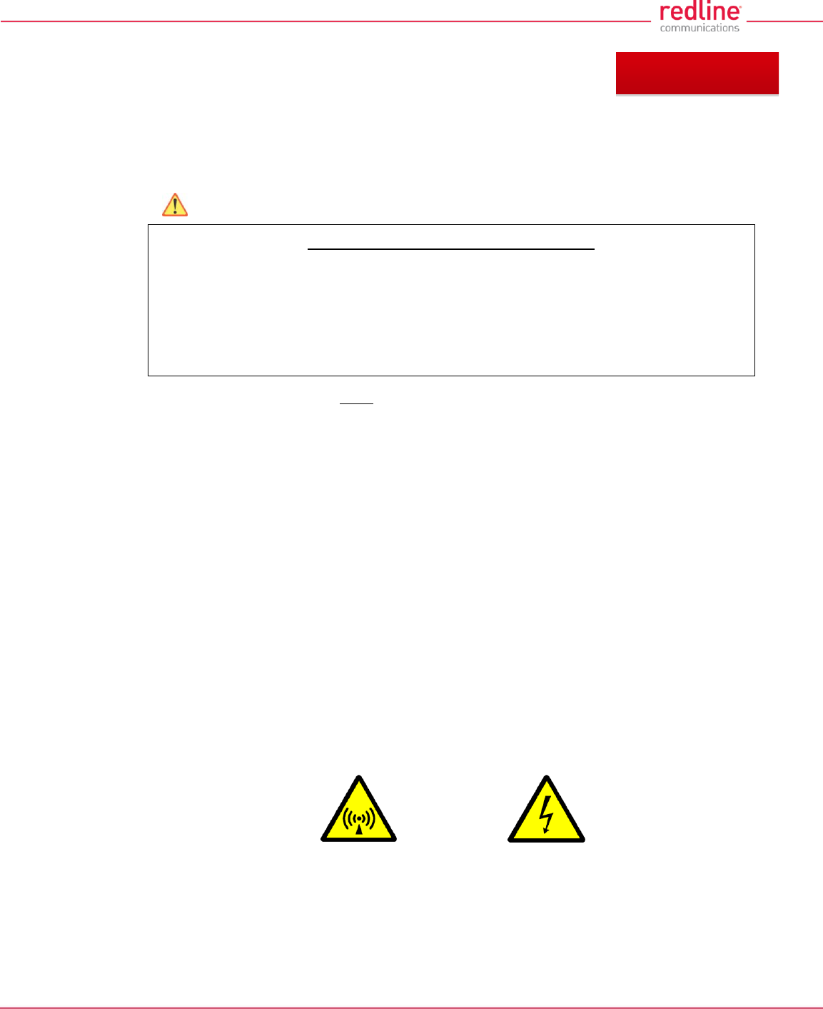
1.1.2 Warning Symbols
These symbols may be encountered during installation or troubleshooting. These
warning symbols mean danger. Bodily injury may result if you are not aware of the safety
hazards involved in working with electrical equipment and radio transmitters. Familiarize
yourself with standard safety practices before continuing.
Electro-Magnetic Radiation
High Voltage
Chapter 1

RDL-3000 User Manual
70-00158-01-DRAFT Proprietary Redline Communications © 2010 Page 14 of 142 November 25, 2010
1.1.3 Lightning Protection
WARNING: This user manual provides notes are general recommendations for the
system. The wireless equipment should be installed by a qualified professional installer
who is knowledgeable of and follows local and national codes for electrical grounding
and safety. Failure to meet safety requirements and/or use of non-standard practices
and procedures could result in personal injury and damage to equipment.
All outdoor wireless equipment is susceptible to lightning damage from a direct hit or
induced current from a near strike. A direct lightning strike may cause serious damage
even if these guidelines are followed. Lightning protection and grounding practices in
local and national electrical codes serve to minimize equipment damage, Service
outages, and serious injury. Reasons for lightning damage are summarized as:
- Poorly grounded antenna sites that can conduct high lightning strike energy into
equipment.
- Lack of properly installed lightning protection equipment can cause equipment
failures from lightning induced currents.
A lighting protection system provides a means by which the energy may enter earth
without passing through and damaging parts of a structure. A lightning protection system
does not prevent lightning from striking; it provides a means for preventing damage to
equipment by providing a low resistance path for the discharge of energy to travel safely
to ground. Improperly grounded connections are also a source of noise that can cause
sensitive equipment to malfunction.
A good grounding system disperses most of the surge energy from a lightning strike
away from the building and equipment. The remaining energy on the Ethernet cable
shield and conductors can be directed safely to ground by installing a lightning arrestor
in series with the cable.
If you have determined that it is appropriate to install lightning protection for your system,
the following general industry practices are provided as a guideline only:
1. The AC wall outlet ground for the indoor POE adapter should be connected to the
building grounding system.
2. Install a lightning arrestor in series with the Ethernet cable at the point of entry to the
building. The grounding wire should be connected to the same termination point
used for the tower or mast.
3. Provide direct grounding connections from the RDL-3000, the mounting bracket, the
antenna, and the Ethernet cable surge protection to the common building ground
bus. Use the grounding screws provided for terminating the ground wires.
1.1.4 Service & Warranty Information
1. Refer all repairs to qualified Service personnel. Do not remove the covers or modify
any part of this device, as this action will void the warranty.
2. Locate the serial numbers and record these for future reference. Use the space
below to affix serial number stickers. Also, record the MAC address identified on the
unit product label.
3. Redline does not endorse or support the use of outdoor cable assemblies: i) not
supplied by Redline, ii) third-party products that do not meet Redline's cable and
connector assembly specifications, or iii) cables not installed and weatherproofed as
specified in the RDL-3000 Installation Guidelines manual. Refer to the Redline
Limited Standard Warranty and RedCare Service agreements.
RDL-3000 User Manual
70-00158-01-DRAFT Proprietary Redline Communications © 2010 Page 15 of 142 November 25, 2010
1.2 Regulatory Notices
1.2.1 Deployment in USA and Canada: FCC & IC Notices
Read the following notices about deployment in the USA and Canada:
1. The Model RDL-3000 and its antenna must be professionally installed.
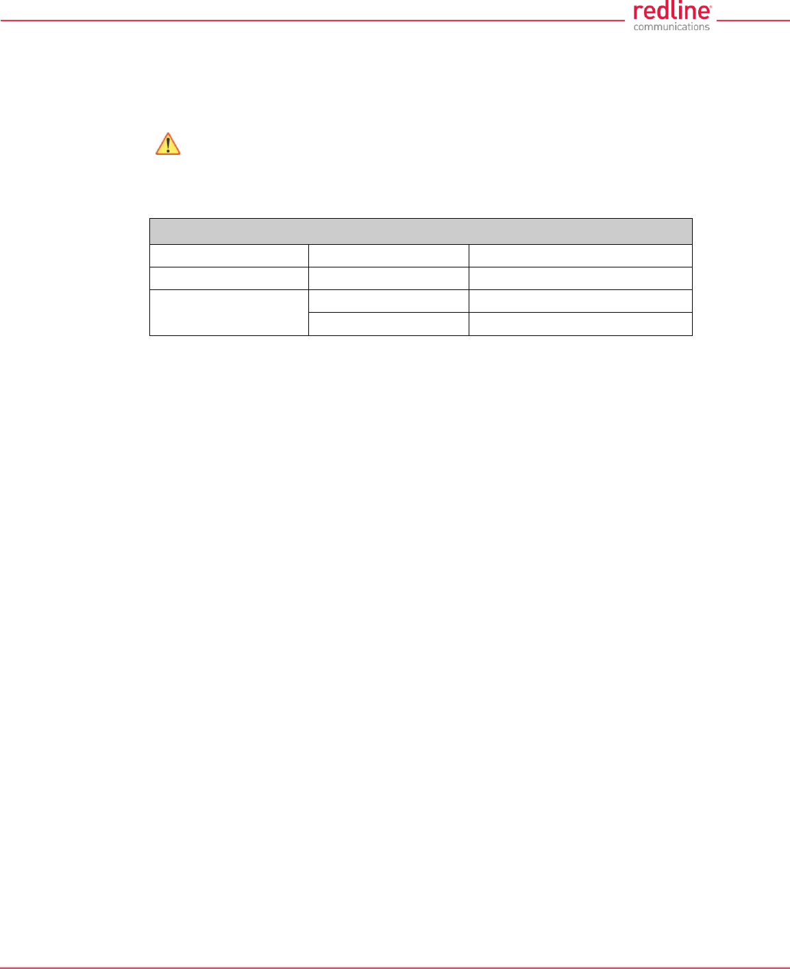
2. WARNING -- FCC & IC RF Exposure Warnings
To satisfy FCC and IC RF exposure requirements for RF transmitting devices, the
following distances should be maintained between the antenna of this device and
persons during device operation:
Table 1: FCC & IC RF Recommended Safe Separation Distances
Frequency (GHz)
Deployment
Separation Distance
4.9 - 5.3
PTP or PMP
270 cm (107 in) or more
5.8
PMP
20 cm (8 in) or more
PTP
270 cm (107 in) or more
To ensure compliance, operation at closer than these distances is not
recommended. The antenna used for this transmitter must not be collocated in
conjunction with any other antenna or transmitter.
3. FCC Information to Users @ FCC 15.105:
NOTE: This equipment has been tested and found to comply with the limits for a
Class B digital device, pursuant to part 15 of the FCC Rules. These limits are
designed to provide reasonable protection against harmful interference in a
residential installation.
This equipment generates, uses and can radiate radio frequency energy and, if not
installed and used in accordance with the instructions, may cause harmful
interference to radio communications. However, there is no guarantee that
interference will not occur in a particular installation. If this equipment does cause
harmful interference to radio or television reception, which can be determined by
turning the equipment off and on, the user is encouraged to try to correct the
interference by one or more of the following measures:
- Reorient or relocate the receiving antenna.
- Increase the separation between the equipment and receiver.
- Connect the equipment into an outlet on a circuit different from that to which the
receiver is connected.
- Consult the dealer or an experienced radio/TV technician for help.
Where DFS is required by regional regulations, this function is permanently enabled
at the factory and can not be disabled by the installer or end-user.
4. FCC Information to Users @ FCC 15.21:
Warning: Changes or modifications not expressly approved by Redline
Communications could void the user’s authority to operate the equipment.

RDL-3000 User Manual
70-00158-01-DRAFT Proprietary Redline Communications © 2010 Page 16 of 142 November 25, 2010
1.2.2 UL Information
1. The suitability of the supplied Ethernet cable is subject to the approval of Authority
Having Jurisdiction and must comply with the local electrical code.
2. The equipment must be properly grounded according with NEC and other local
safety code and building code requirements
3. To meet the over-voltage safety requirements on the telecommunications cables, a
minimum 26 AWG telecommunication line cord must be used.
4. "Pour être en conformance avec les exigences finies de sûreté de sur-tension sur les
câbles de télécommunications un fil de télécommunication ayant un calibre minimum
de 26 AWG doit être utilisé."
5. Reminder to all the BWA system installers: Attention to Section 820-40 of the NEC
which provides guidelines for proper grounding and, in particular, specifies that the
cable ground shall be connected to the grounding system of the building, as close to
the point of cable entry as is practical.
6. RDL-3000 must be installed in compliance with relevant articles in National
Electrical Code-NEC (and equivalent Canadian Code-CEC) including referenced
articles 725, 800 and 810 in NEC.
7. RF coaxial cable connecting an antenna to the RDL-3000 must comply with the
local electrical code.
RDL-3000 User Manual
70-00158-01-DRAFT Proprietary Redline Communications © 2010 Page 17 of 142 November 25, 2010
2 System Features
2.1 General Description
The RDL-3000 system is manufactured by Redline Communications -- a world leader in
design and production of Broadband Fixed Wireless (BFW) systems.
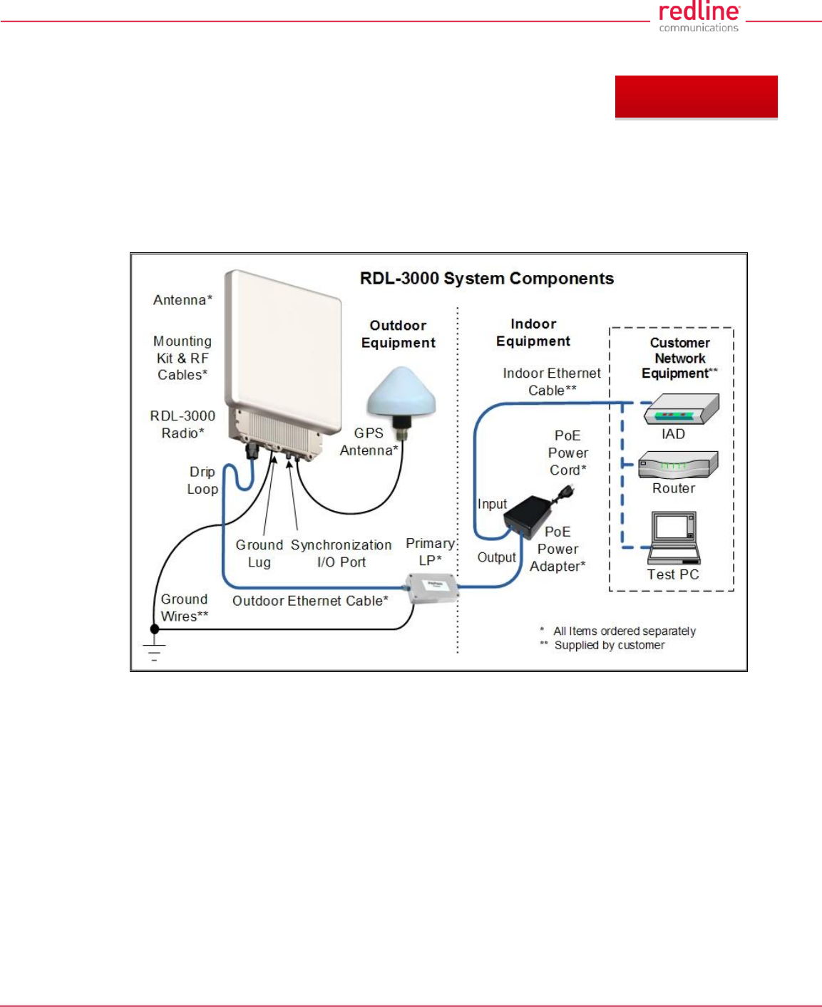
Fig. 1: Intro - RDL-3000 System Components
RDL-3000 is a high-performance, high-speed wireless Ethernet bridge. The system
operates in the 4.9 - 5.8 GHz band using two time division duplexing (TDD) RF
transceivers to transmit and receive on the same. Main features include advanced
technologies to address inter-cell interference and enhanced security features that
provide over-the-air encryption.
The RDL-3000 outdoor unit is housed in a weatherproof aluminum alloy case. An indoor
PoE power adapter provides operational power for the RDL-3000 and connection to the
Ethernet network. The outdoor unit can be used with a selection of antennas.
One RDL-3000 must be configured as a Sector Controller (PMP SC) to control all RF
transmissions in a sector that may contain many subscribers. The Sector Controller uses
a scheduled request/grant mechanism to arbitrate bandwidth requests from the remote
unit PMP subscribers to provide non contention-based traffic with predictable
transmission characteristics. One or more RDL-3000 units may be configured as
subscriber units (PMP SS) controlled by the Sector Controller.
Chapter 2
RDL-3000 User Manual
70-00158-01-DRAFT Proprietary Redline Communications © 2010 Page 18 of 142 November 25, 2010
Note: PMP and PTP modes of operation are controlled by options keys. Refer to these
sections of the manual for additional details.
2.2 Ethernet Port
The Ethernet port (female RJ-45 connector) receives DC power and exchanges data
with the local network. The Ethernet port connects to the PoE Adapter using a
weatherproof CAT-5e Ethernet cable. The maximum total length of the Ethernet cable is
100 m (328 ft). For example, 98 m from the RDL-3000 to the PoE and 2 m from the PoE
to the local network equipment.
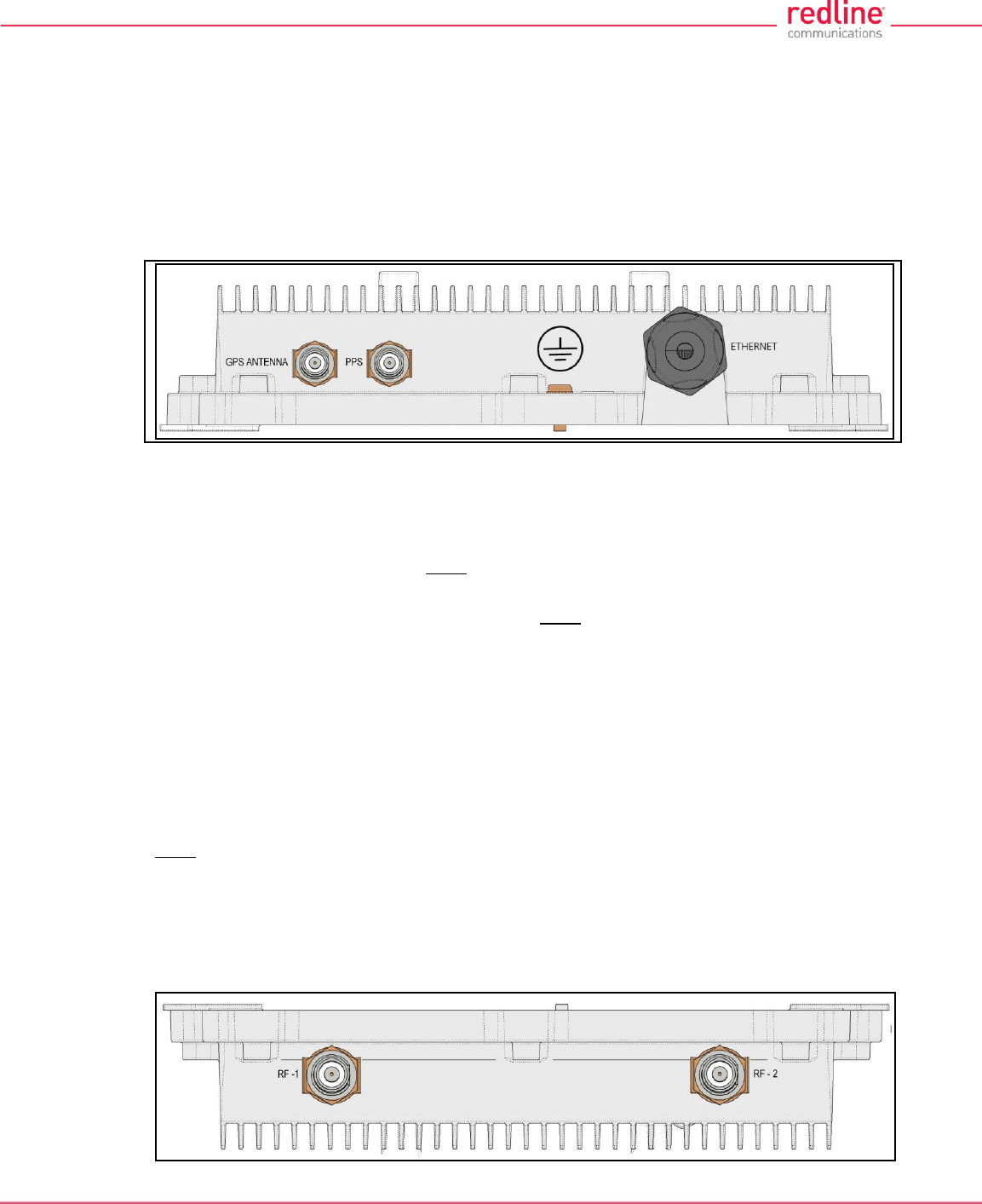
Fig. 2: Intro - RDL-3000 - Ethernet and Sync Ports (Bottom View of Radio)
2.3 Synchronization I/O Port (PPS)
The PPS port (TNC / F) connector. The function of this port is determined by the
software configurable settings. A protective weatherproof plastic cap is installed on this
port for all new units. This port must be weatherproofed when a synchronization cable
and/or BNC Tee connector is installed.
Note: The RDL-3000 synchronization feature must be used to minimize inter-sector RF
interference at any site where two or more base stations are deployed. This feature
synchronizes the transmit and receive cycles of collocated RDL-3000 base stations to
minimize inter-sector interference. Up to four collocated base stations may be controlled
using the synchronization cables. A GPS receiver is required at each site when the site
is part of a network of geographically collocated cells.
2.4 GPS Antenna Port (GPS ANTENNA)
The GPS antenna port (TNC / F) is available only on RDL-3000 units factory-equipped
with GPS hardware. This port receives signals from a GPS antenna. A protective
weatherproof plastic cap is installed on this port for all new units. The GPS antenna port
must be weatherproofed when a GPS antenna cable is installed.
2.5 RF Ports
The two RF ports are female N-type connectors. The ports conduct RF signals between
the RDL-3000 and the antenna system (ordered separately). Short coaxial cable(s) are
provided to connect the transceiver to an external antenna. The RDL-3000 can be
operated using a SISO (single antenna) or MIMO (multiple antenna_ system.
RDL-3000 User Manual
70-00158-01-DRAFT Proprietary Redline Communications © 2010 Page 19 of 142 November 25, 2010
Fig. 3: Intro - RDL-3000 RF Ports (Top View of Radio)
Note: For SISO mode, the antenna can be connected to either RF port. Select the
antenna port using the Web interface (Configuration->Wireless->Radio Mode). The
unused RF port must be sealed and weatherproofed.
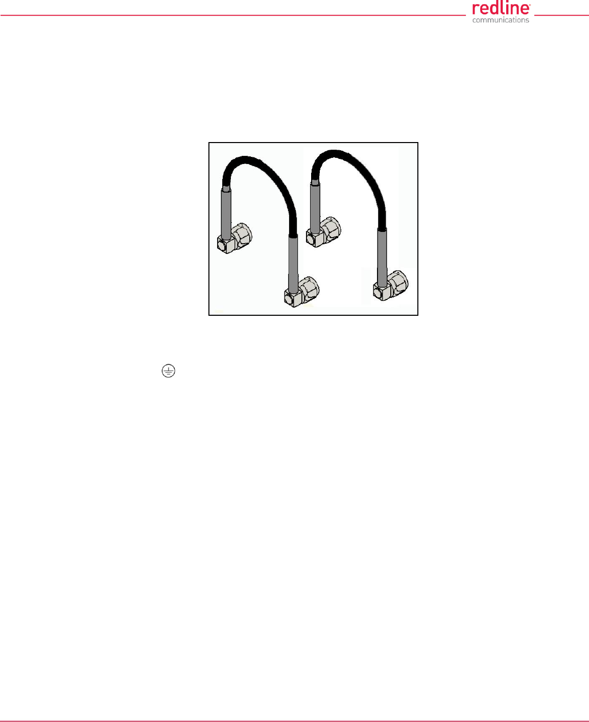
Two RF jumper cables are provided with each mounting kit. The RF cables conduct RF
signals between the RDL-2000 and antenna system. Each 75 cm (29.5 in) cable is
terminated female N-type to TNC.
Fig. 4: Intro - RDL-3000 - RF Jumper Cables
2.6 Ground Lug
A ground-lug is provided on the RDL-3000 chassis. Use this connection to terminate
a grounding wire. All RDL-3000 systems must be properly grounded to protect against
power surges and accumulated static electricity.
2.7 Audible Alignment
When enabled, the audible alignment signal chirps slowly when a low signal level is
detected, and faster for stronger signals. To enable or disable the audible tool through
the user interface:
Web: See Antenna Alignment Buzzer Enable in the Wireless Configuration screen.
Telnet: See 'buzzer' listed under the CLI 'set' commands (e.g., set buzzer on).
RDL-3000 User Manual
70-00158-01-DRAFT Proprietary Redline Communications © 2010 Page 20 of 142 November 25, 2010
2.8 Management Interfaces
The operator can use a standard web browser to access all settings and statistics
necessary to configure and monitor the operation of the RDL-3000. All functions are also
supported using the Command Line Interface (CLI) using Telnet (see page 95). The
RDL-3000 can also be configured monitored using SNMP (documentation provided
separately). If the IP address, username and/or password have been modified since
installation, contact the network administrator to determine the current settings.
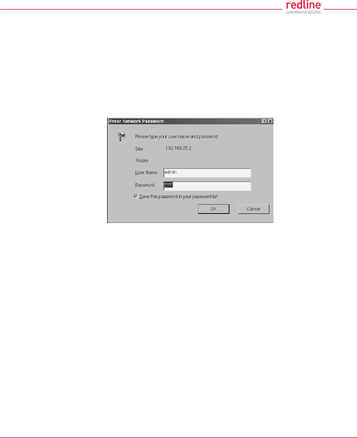
2.8.1 Web Browser (HTTP)
Open a Web browser (Internet Explorer 6 or higher recommended) and enter the unit IP
address. For new systems, the default IP address is 192.168.25.2. The following login
dialog should be displayed:
Fig. 5: Intro - Web Login to the RDL-3000
There is no logout command on the Web interface.
2.8.2 Telnet (CLI)
The RDL-3000 supports two concurrent Telnet sessions. One session with full read/write
capabilities (administrator) and a second concurrent session with read-only access (e.g.,
monitor or show parameter settings).
To connect to the RDL-3000 CLI management, open a Telnet session to the IP address
of the RDL-3000. When the command prompt screen appears, login to the RDL-3000.
Users are logged out automatically when no commands are received (idle) for a period
of ten minutes. Type the following command to exit immediately from the CLI:
logout [ENTER]
2.8.3 SNMP
The RDL-3000 can also be configured and monitored using SNMP (v2c/v3). The Redline
Management Information Base (MIB) is available to operators (documentation provided
separately). The Redline Management Suite is a set of applications designed to assist
provisioning, monitoring and maintaining the Redline components deployed in Radio
Access Networks (RANs). Contact your Redline representative or visit the Redline
website for further information.
RDL-3000 User Manual
70-00158-01-DRAFT Proprietary Redline Communications © 2010 Page 21 of 142 November 25, 2010
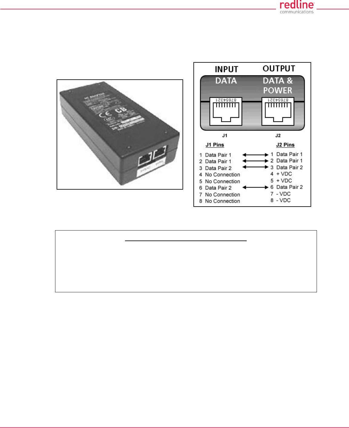
2.9 PoE Power Adapter
The PoE power adapter (Standard IEEE 802.3at PoE, 25 W max.) provides power and
connectivity to a local Ethernet network. The AC power adapter input is auto-sensing
110/220/240 VAC 50/60 Hz.
Fig. 6: Intro - Indoor Power-over-Ethernet (PoE) Module - AC Model
Warning to Service Personnel: 48 VDC
Customer equipment including personal computers, routers, etc., must be connected
only to the INPUT (DATA) port on the PoE unit. Only the outdoors Ethernet interface
cable connecting to the RDL-3000 can be safely connected to the OUTPUT (DATA &
POWER) connector. Connecting customer premises Ethernet equipment directly to
the OUTPUT (DATA & POWER) connector on the Power-over-Ethernet power
adapter may damage customer equipment.
RDL-3000 User Manual
70-00158-01-DRAFT Proprietary Redline Communications © 2010 Page 22 of 142 November 25, 2010
3 Functional Overview
Operation in PMP mode is controlled by the options keys. When a PMP-only options key
is activated, the RDL-3000 operation is restricted to the number of purchased subscriber
connections. This mode is not equivalent to operating the RDL-3000 in PTP mode with
multiple remote units. Enter PMP-only options keys before deploying and configuring the
RDL-3000 units.
The GUI and Telnet functions are identical for PMP and PTP operation. It is required to
configure one unit as the master (PMP SC) and all remote units as subscribers (PMP
SS). A separate range of RF power settings are provided for PMP operation. The
graphical user interface (GUI) and Telnet functions are identical for both PTP and PMP
operation. The RDL-3000 can also be configured and monitored using SNMP
(documentation provided separately).
Note: Refer to the RDL-3000 installation Guidelines for additional information about
installing and operating the RDL-3000 in PMP mode.
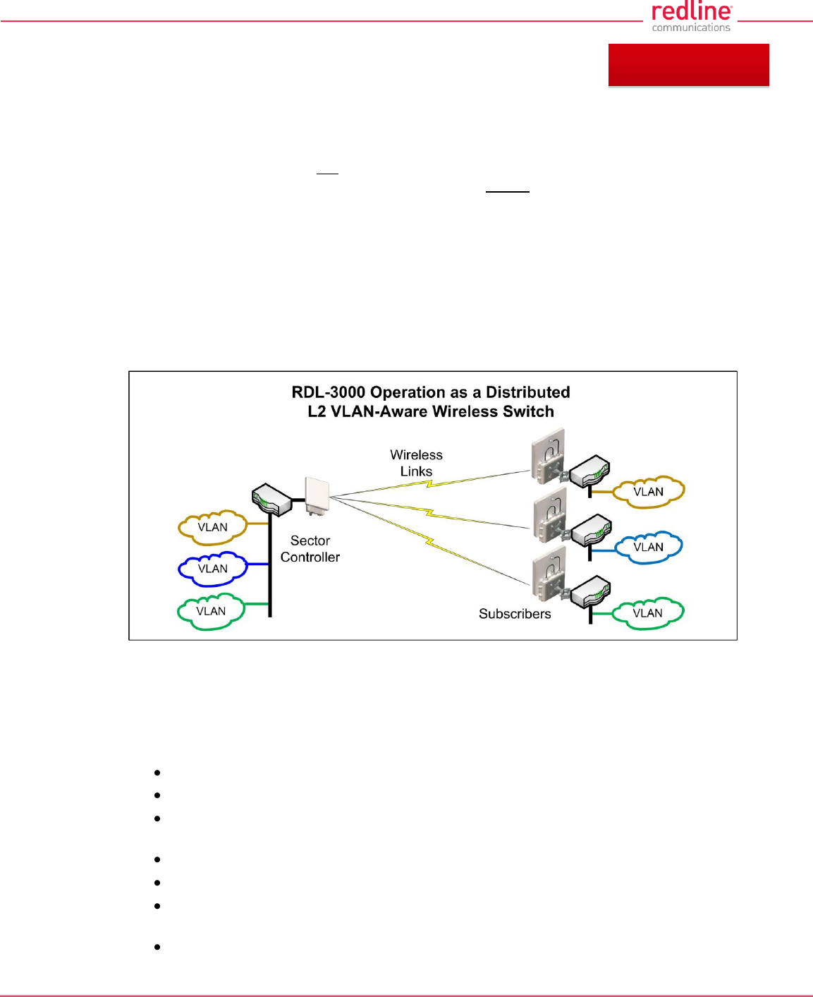
Fig. 7: PMP - RDL-3000 Distributed L2 VLAN-Aware Wireless Switch
3.1 Overview
This section describes only the additional parameters required for configuring PMP
support, and an overview about defining and using VLAN and pass-through groups.
The RDL-3000 PMP firmware provides the following main features:
IEEE 802.1Q/1p standards compliance
Multiple Virtual Local Area Network (VLAN) services per subscriber
Individual Committed Information Rate (CIR) and Peak Information Rate (PIR)
setting per service
VLAN Service Groups span subscribers
VLAN tagged management traffic
Multiple Transparent LAN Services (TLS) transport based on VLAN ID
classification
VLAN trunking with tag insert/delete/re-map
Chapter 3
Chapter 3
RDL-3000 User Manual
70-00158-01-DRAFT Proprietary Redline Communications © 2010 Page 23 of 142 November 25, 2010
3.2 PMP Mode
The RDL-3000 can operate as a VLAN-aware wireless L2 switch, with traffic being
classified and processed based on the packet VLAN ID. The RDL-3000 also provides a
Pass through mode that can be used to process traffic that is not matched to a known
VID, or simply to forward all traffic received on a port.
The deployed RDL-3000 wireless network provides features of a standard wireless L2
bridge (pass-through mode) and a VLAN-aware wireless L2 switch (tagged mode).
These features and other system capabilities are explained in the following sections.
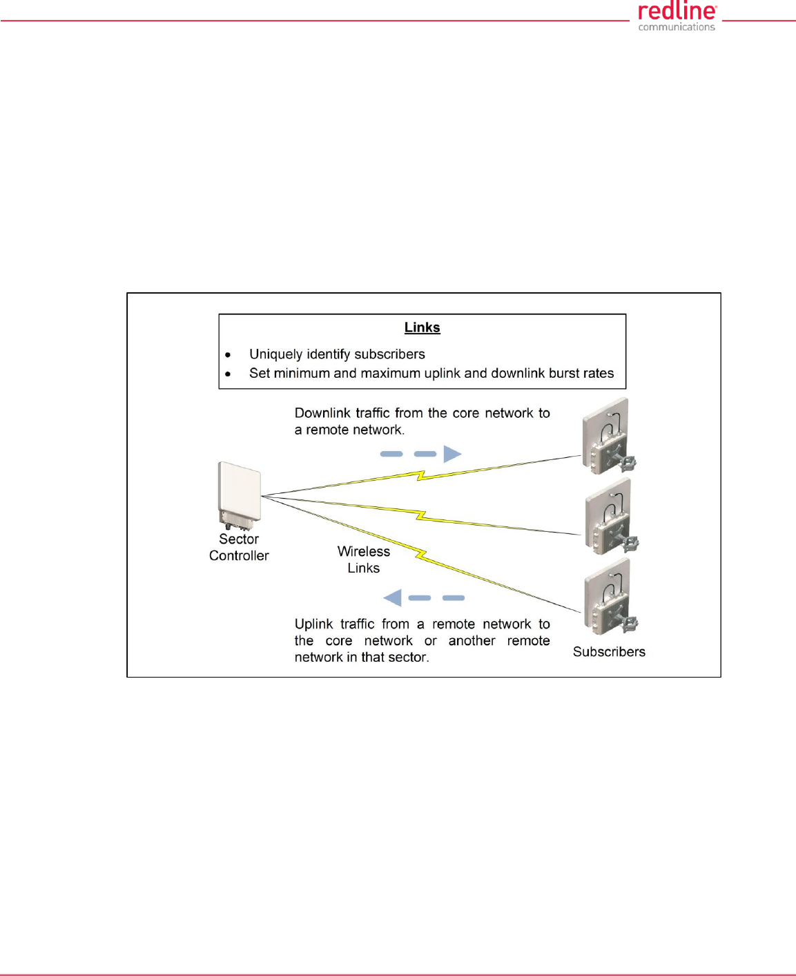
3.2.1 Subscriber Links
Subscriber Links define the characteristics of the wireless interfaces between the sector
controller and subscribers. Each link is uniquely identified with a name and MAC
address. The uplink and downlink uncoded burst rates (UBR) can be set individually for
each link in the sector.
Fig. 8: PMP - Wireless Subscriber Links
RDL-3000 User Manual
70-00158-01-DRAFT Proprietary Redline Communications © 2010 Page 24 of 142 November 25, 2010
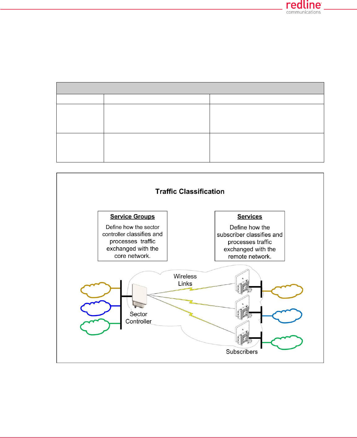
3.2.2 Services and Service Groups
The RDL-3000 can operate as a VLAN-aware wireless L2 switch, with traffic being
classified and processed based on the packet VLAN ID. The RDL-3000 also provides a
Pass through mode that can be used to process traffic that is not matched to a known
VID, or simply to forward all traffic received on a port.
The following table lists the two methods to classify and process traffic received at the
RDL-3000 Ethernet port.
Table 2: Web - Operation - Traffic Classification
Type
Function
Settings
Service
Classify and process traffic received
and transmitted over the subscriber
Ethernet port.
Tagging Mode (VLAN/Pass through)
VLAN ID (tag)
Default Priority
Service
Group
Classify and process traffic received
and transmitted over the sector
controller Ethernet port.
Tagging Mode (VLAN/Pass through)
VLAN ID (tag)
Default Priority
Fig. 9: PMP - Services and Service Groups
See the following sections for additional information about Service Groups and Services.
RDL-3000 User Manual
70-00158-01-DRAFT Proprietary Redline Communications © 2010 Page 25 of 142 November 25, 2010
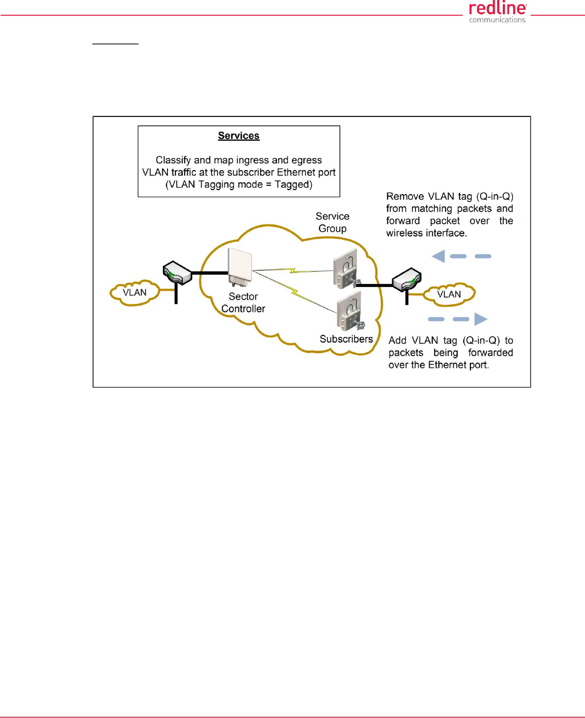
Services
Services are used to classify and process ingress and egress packets on the subscriber
Ethernet port, and to set wireless uplink and downlink rates for unicast traffic to/from the
host subscriber. Service settings include VLAN ID (tag), default priority, parent Link, and
parent Service Group. See 3.2.3: Setting Wireless Rates on page 27 for wireless rate
settings.
Fig. 10: PMP - Services (Subscriber)
If the Ethernet port ingress packet has a VLAN tag and the VID matches a Service
Group, the VLAN tag is removed (Q-in-Q) and the packet is forwarded over the wireless
interface.
Packets received over the wireless link are processed by the Service associated with the
originating parent Service Group. If the VLAN Tagging mode is 'tagged', a VLAN tag with
the Service VID is added to the packet (Q-in-Q), and the packet is forwarded over the
subscriber Ethernet port.
Note: At least one Service Group (sector controller) and one Service (subscriber) must
be defined before Ethernet traffic can be exchanged over the wireless interface.
RDL-3000 User Manual
70-00158-01-DRAFT Proprietary Redline Communications © 2010 Page 26 of 142 November 25, 2010
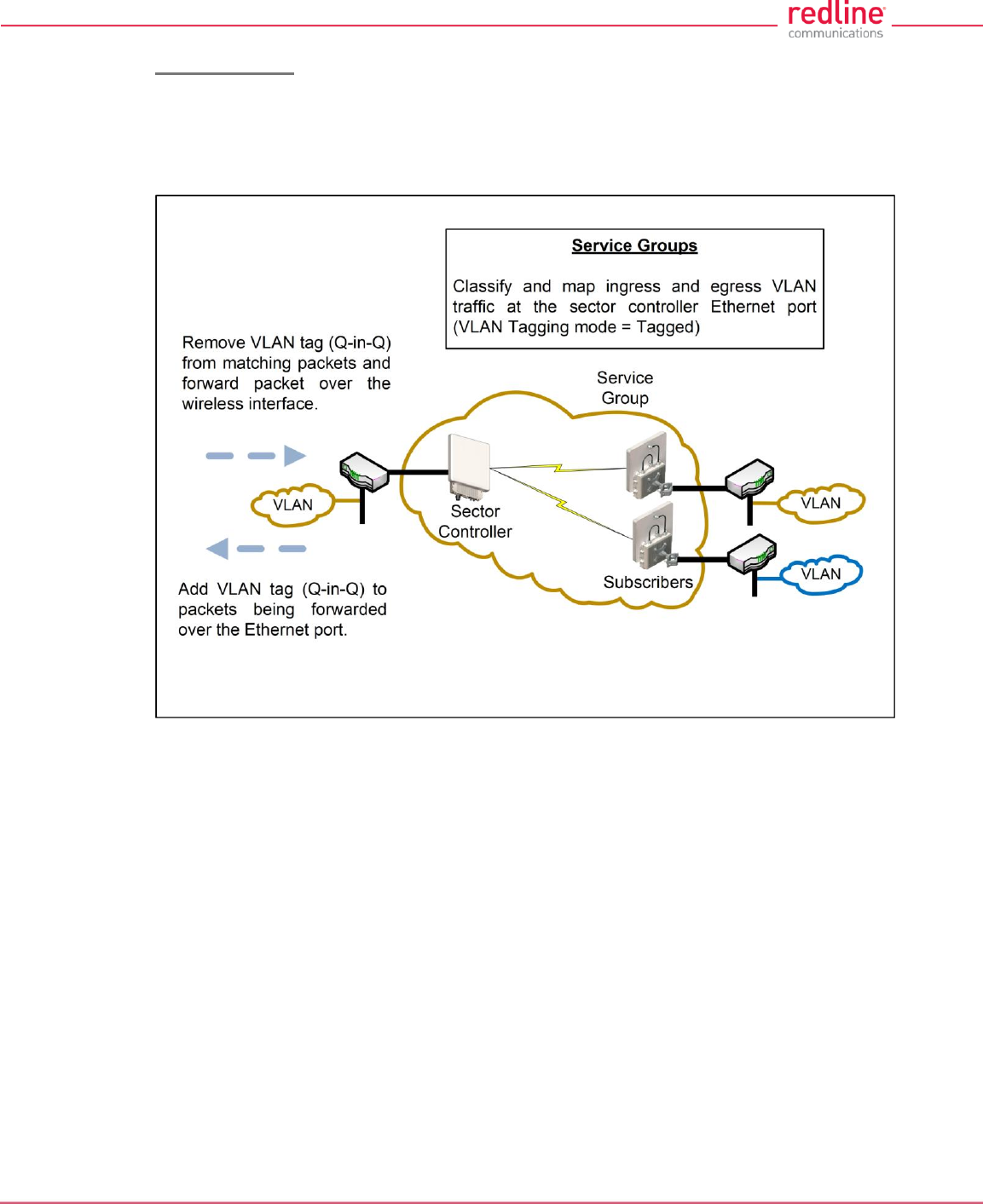
Service Groups
Service Groups classify and process ingress and egress packets on the sector controller
Ethernet port, and to set wireless broadcast and multicast rates for Service Group
members (broadcast group). Service Group settings include VLAN ID (tag), default
priority, and broadcast rates. See 3.2.3: Setting Wireless Rates on page 27 for wireless
rate settings.
Fig. 11: PMP - Service Groups (Sector Controller)
If the Ethernet port ingress packet has a VLAN tag and the VID matches a Service
Group, the VLAN tag is removed (Q-in-Q) and the packet is forwarded over the wireless
interface. Unicast packets addressed to a Service Group member are forwarded only to
that host subscriber. Broadcast, multicast, and unknown unicast packets are forwarded
to all Service Group members.
Packets received over the wireless link are processed by the parent Service Group of
the originating Service. If the VLAN tagging mode is 'tagged', a VLAN tag with the
Service Group VID is added to the packet (Q-in-Q), and the packet is forwarded over the
Ethernet port.
Note: At least one Service Group (sector controller) and one Service (subscriber) must
be defined before Ethernet traffic can be exchanged over the wireless interface.
RDL-3000 User Manual
70-00158-01-DRAFT Proprietary Redline Communications © 2010 Page 27 of 142 November 25, 2010
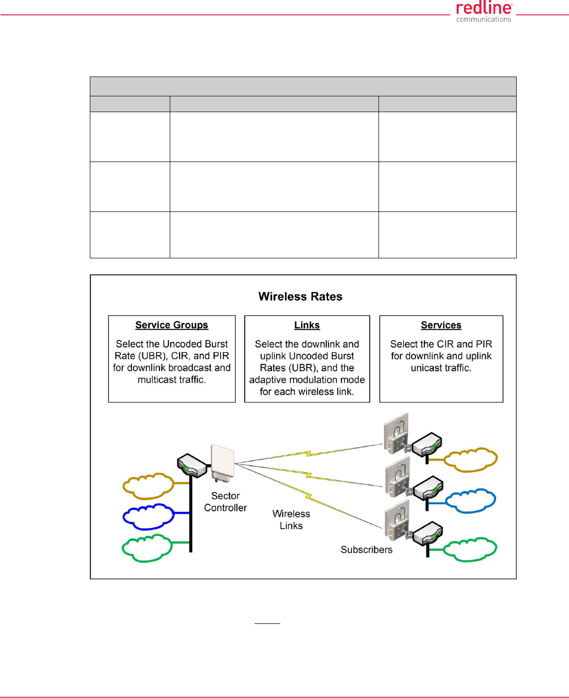
3.2.3 Setting Wireless Rates
The wireless bandwidth is shared between all subscribers in a sector. Use the following
settings to control traffic rates over the wireless interface.
Table 3: Web - Operation - Wireless Rates`
Type
Function
Wireless Settings
Link
Select the Uncoded Burst Rate (UBR) for the
link to this subscriber. The RDL-3000 sets
the modulation and coding settings required
to provide the selected rate.
Downlink UBR
Uplink UBR
Adaptive modulation mode
Service
Select the uplink and downlink Committed
Information Rates (CIR) and peak
Information Rates (PIR) rates for unicast*
traffic to/from this subscriber.
Downlink CIR / PIR
Uplink CIR / PIR
Service
Group
Set the rates for downlink multicast and
broadcast traffic belonging to this group.
Downlink Burst rate
Downlink CIR / PIR
Fig. 12: PMP - Wireless Rates
*Unicast traffic with an unknown destination (all RDL-3000 units maintain a forwarding table) is
transmitted two modulation steps below the lowest rate currently in-use across all active
Services.
RDL-3000 User Manual
70-00158-01-DRAFT Proprietary Redline Communications © 2010 Page 28 of 142 November 25, 2010
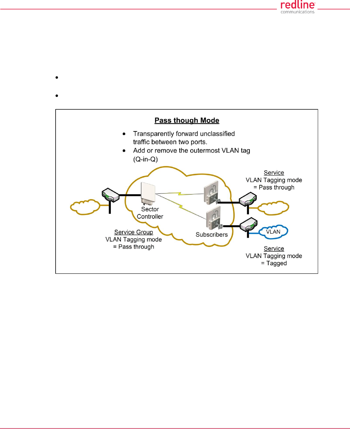
3.2.4 Pass through Mode
Pass through mode is used to process traffic that is untagged or where the VLAN tag
does not match the VID of any Service or Service Group. Ingress and egress packets
processed by a Service Group or Service set to 'Pass through' mode are forwarded
without modification.
Pass through mode can be used to:
Transparently forward all unclassified traffic between two ports (both ports are 'Pass
though' mode).
Add or remove the outermost VLAN tag (Q-in-Q), depending on the direction of the
traffic (only one port is using 'Pass though' mode).
Fig. 13: PMP - Pass through Mode
Notes:
1. Only one Service Group (sector controller) may be set to 'Pass though' mode.
2. Only one Service on a subscriber may be set to 'Pass though' mode.
RDL-3000 User Manual
70-00158-01-DRAFT Proprietary Redline Communications © 2010 Page 29 of 142 November 25, 2010
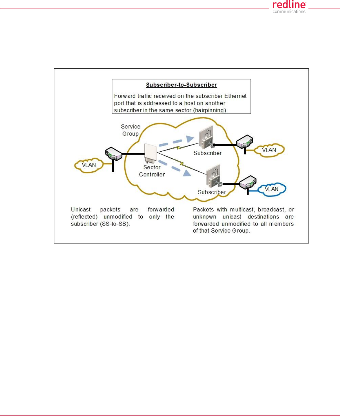
3.2.5 Subscriber-to-Subscriber Traffic
SS to SS traffic is any packet received on a subscriber Ethernet port that is addressed to
a host on another subscriber in the same sector. Unicast traffic is forwarded to the sector
controller and then retransmitted (unmodified) over the wireless interface to the
destination subscriber. Broadcast and multicast traffic is forwarded to the sector
controller and processed by the parent Service Group of the originating Service.
Fig. 14: PMP - Subscriber-to-Subscriber Unicast Traffic
Notes:
1. SS to SS broadcast and multicast traffic may optionally be blocked.
RDL-3000 User Manual
70-00158-01-DRAFT Proprietary Redline Communications © 2010 Page 30 of 142 November 25, 2010
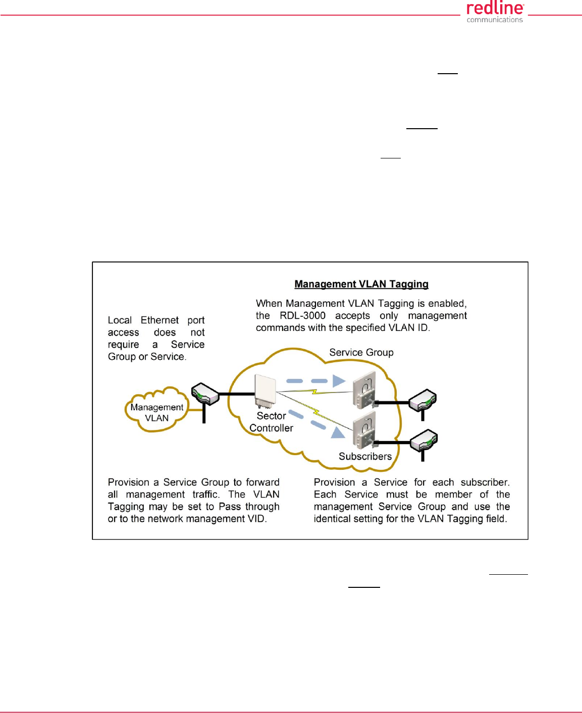
3.2.6 VLAN Tagged Management
When Management VLAN Tagging is enabled, the management VID must be
specified. When this feature is enabled, the RDL-3000 recognizes only management
commands with this VID.
For management using the local Ethernet port, it is not required to create a Service
Group (sector controller) or Service (subscriber). When Management VLAN Tagging is
enabled, the VLAN tags on ingress packets are checked before the packets are
submitted for classification to a Service Group or Service.
Over-the-air management on PMP systems is possible only after creating a Service
Group to classify the management traffic and a member Service for each participating
subscriber. The Service Group and member Services should all specify the same VID.
Select CIR and priority values that ensure adequate bandwidth and priority for
management traffic during normal system operation. For network security, over the air
management is only available from the sector controller.
For initial installation and setup, it is recommended to use Pass through mode for the
management Service Group and member Services.
Fig. 15: PMP - VLAN Tagged Management
Note: If the Management VLAN Tagging feature is to be used, it is strongly
recommended to create and test VLAN connectivity before enabling VLAN Management.
If any connectivity issue exists with VLAN services, the RDL-3000 unit management
functions will be unreachable and a site visit and/or long reset operation may be required
to recover control of the unit.
RDL-3000 User Manual
70-00158-01-DRAFT Proprietary Redline Communications © 2010 Page 31 of 142 November 25, 2010
3.2.7 PMP Configurations
This section provides basic configuration scenarios that illustrate the flexibility inherent in
the RDL-3000 design.
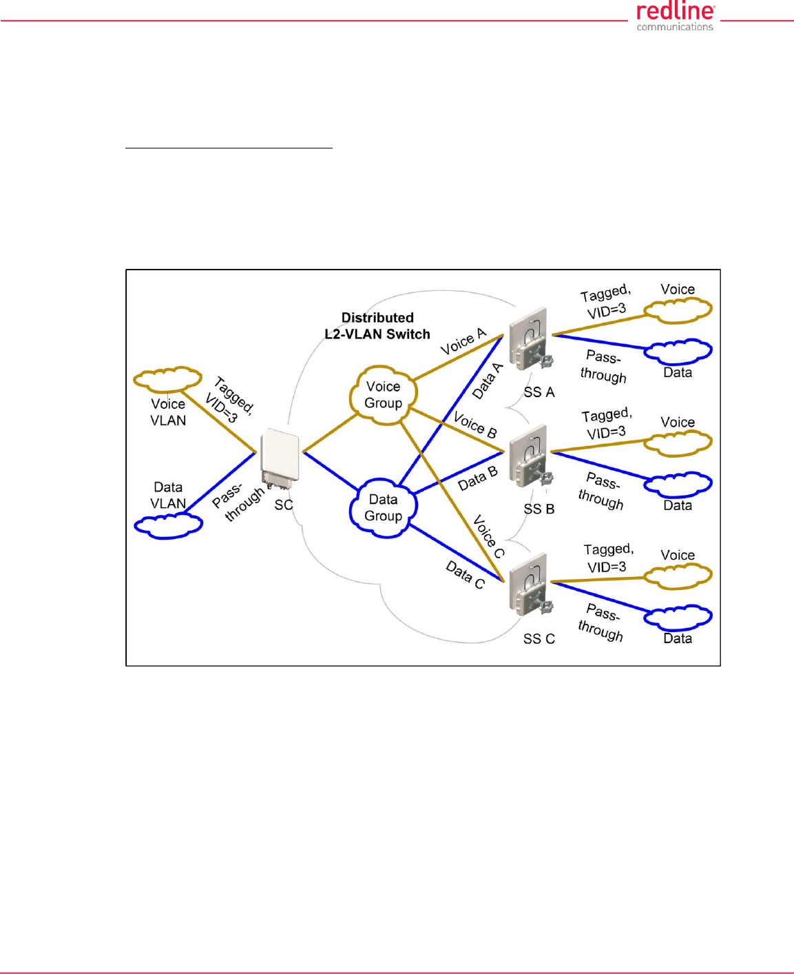
VLAN Services
Default Groups and Services
Fig. 16 displays an example of VLAN usage where all traffic not classified to the Voice'
Group is classified to the Data Group. The 'Voice' Group and Services are configured for
tagged traffic, and the Data Group and Connections are configured for pass-through
mode.
Note: This configuration does not enforce a Service Group to have a Service on every
subscriber, or be enabled to the sector controller Ethernet port.
Fig. 16: PMP - Operation - VLAN Services - Default Groups and Services
RDL-3000 User Manual
70-00158-01-DRAFT Proprietary Redline Communications © 2010 Page 32 of 142 November 25, 2010
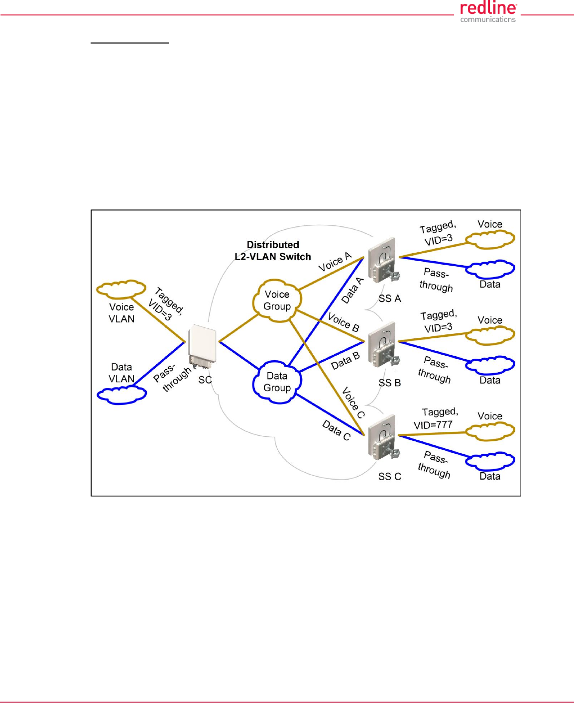
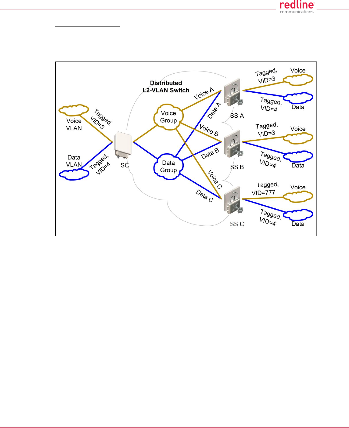
VLAN Mapping
Fig. 17 displays an example of the RDL-3000 VLAN mapping feature. Similar to Label
Switch Router (LSR) in Multi-protocol Label Switching (MPLS), the RDL-3000 PMP
system can map (change) the VLAN tag based on the ingress and egress port. The
VLAN tagging can be specified separately for each Service Group (sector controller port)
and Service (subscriber port).
In this example, the VLAN tag for Service Group 'Voice', and Services 'Voice A' and
'Voice B' are set to VID=3, and the VLAN tag for 'Voice C' is set to VID=777.
Ingress packets with VID=3 received on the sector controller Ethernet port are classified
to the 'Voice Group'. These packets are forwarded over the wireless interface to
members of this Service Group (based on packet destination address). Packets
addressed to subscriber A or B will be tagged with VID=3, while packets addressed to
subscriber C will be tagged with VID=777.
Fig. 17: PMP - Operation - VLAN Services - VLAN Mapping
Ingress broadcast and multicast traffic with VID=3 arriving at the sector controller
Ethernet port is classified to the 'Voice' Services Group (VID=3), and be forwarded over
the wireless interface to all group members, and will exit the Ethernet port on Subscriber
A and B tagged with VID=3, and Subscriber C tagged with VID=777.
RDL-3000 User Manual
70-00158-01-DRAFT Proprietary Redline Communications © 2010 Page 33 of 142 November 25, 2010
Strict VLAN Tagging
Fig. 18 displays an example of VLAN usage where only tagged traffic is allowed to pass
through the system. If a Subscriber port has no pass-through connection, or the Sector
Controller port has no pass-through group, then that port does not accept untagged
traffic or tags that are not explicitly configured.
Fig. 18: PMP - Operation - Strict VLAN Tagging
RDL-3000 User Manual
70-00158-01-DRAFT Proprietary Redline Communications © 2010 Page 34 of 142 November 25, 2010
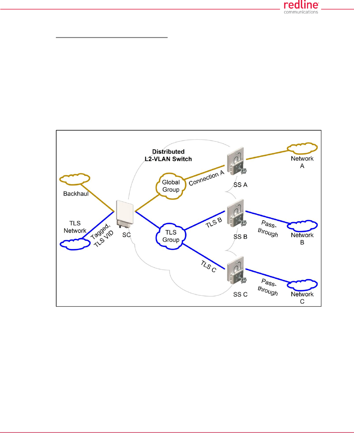
TLS (Transparent LAN Services)
Extended TLS and Double Tagging
Fig. 19 displays an extension of this configuration in which the TLS is extended via the
Sector Controller and over the backbone to other locations. In order to keep the TLS
traffic separate from the rest of the network, the Sector Controller port for the TLS Group
is configured 'tagged' by a user-specified VID referred to in this example as TLS VID.
This solution allows unmodified traffic to be exchanged between Network B, Network C,
and a remotely located network called TLS Network. If Subscriber B receives a tagged
Ethernet packet from Network B, or Subscriber C receives a tagged Ethernet packet
from Network C, the packet will exit the Sector Controller port double-tagged (Q-in-Q).
When the Sector Controller receives a double-tagged packet from the TLS network that
is classified into the TLS Group, the outer tag is removed before the packet is forwarded
to Network B or C.
Fig. 19: PMP - Operation - TLS - Extended TLS and Double Tagging
RDL-3000 User Manual
70-00158-01-DRAFT Proprietary Redline Communications © 2010 Page 35 of 142 November 25, 2010
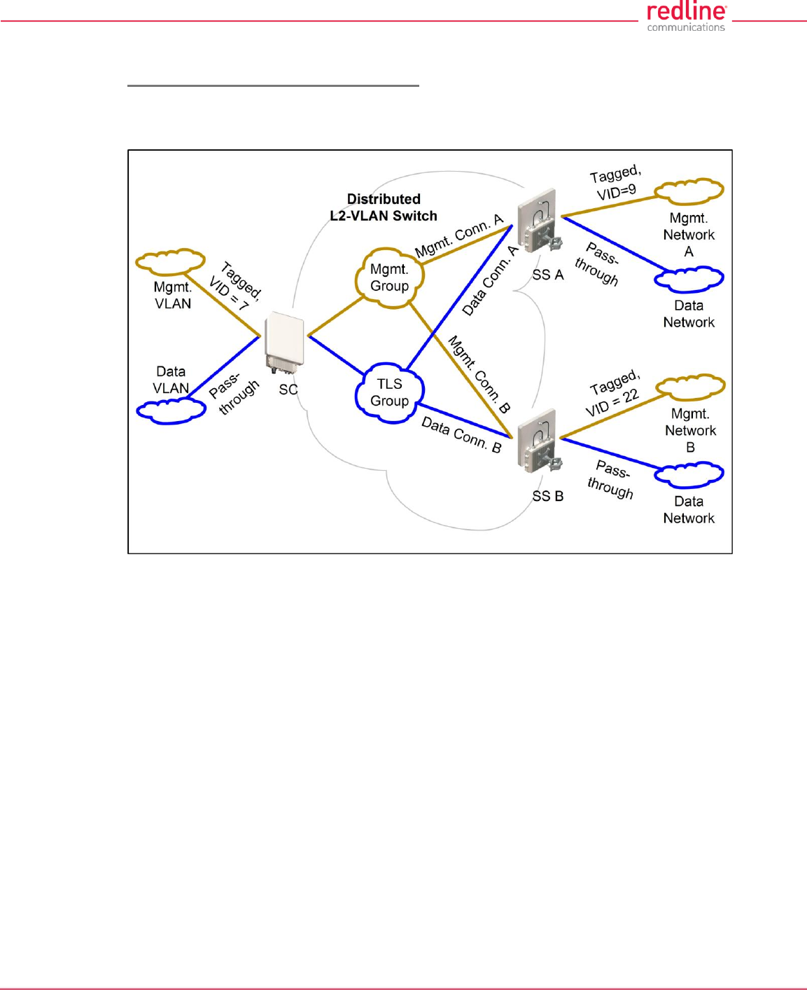
Tagged Traffic
Using a Designated Management Group
Fig. 20 describes a system management scenario where management traffic is tagged
at the Sector Controller as well as the Subscribers. The system will map (change) the
VLAN tags depending on the ingress and egress ports.
Fig. 20: PMP - Operation - Tagged Traffic - Designated Management Group
RDL-3000 User Manual
70-00158-01-DRAFT Proprietary Redline Communications © 2010 Page 36 of 142 November 25, 2010
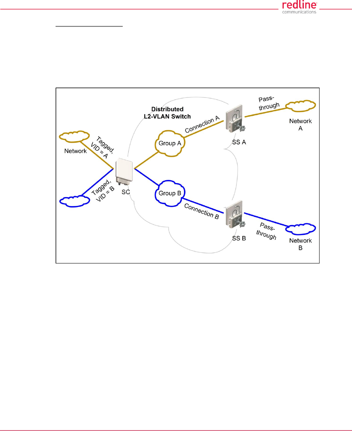
Port-by-Port Tagging
Fig. 21 displays an example of port-based tagging in which all Subscriber ports are
untagged and the Sector Controller port traffic is tagged based-on the source or
destination subscriber. For every tag at the Sector Controller, a distinct group is defined
and each group has exactly one connection on the required link (Subscriber port).
Note that the tagged port is not necessarily the Sector Controller port, and may be one
of the Subscriber ports. Note also in Fig. 21 that tagged traffic entering one of the
Subscribers exits the Sector Controller port double-tagged.
Fig. 21: PMP - Operation - Tagged Traffic - Port-by-Port Tagging
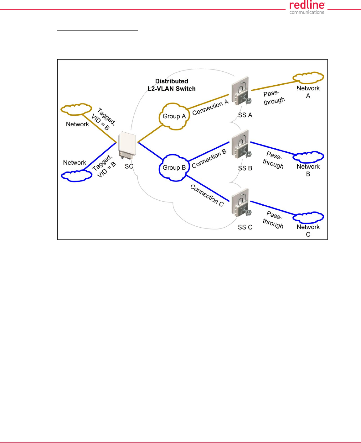
RDL-3000 User Manual
70-00158-01-DRAFT Proprietary Redline Communications © 2010 Page 37 of 142 November 25, 2010
Tagging Groups of Ports
Fig. 22 displays an extension of the previous port-by-port tagging example where a
group can have more than one connection (i.e., the same tag extends over a number of
Subscriber ports).
Fig. 22: PMP - Operation - Tagged Traffic - Tagging Groups of Ports
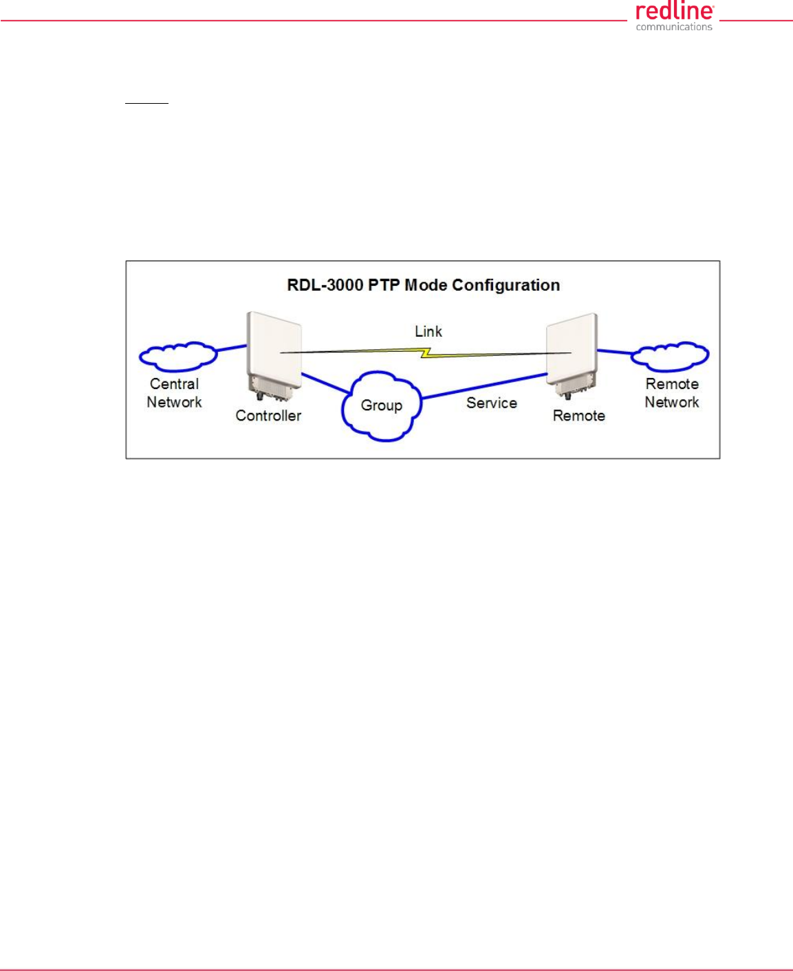
RDL-3000 User Manual
70-00158-01-DRAFT Proprietary Redline Communications © 2010 Page 38 of 142 November 25, 2010
3.3 PTP Mode
Operation in PTP mode is controlled by the options keys. Enter PTP-only options keys
before deploying and configuring the RDL-3000 units. When a PTP-only options key is
activated, the RDL-3000 operation is restricted to a single point-to-point connection. A
separate range of RF power settings are provided for PTP operation.
The GUI and Telnet functions are identical for PTP and PMP operation. It is required to
configure one unit as the controller (PMP SC) and one unit as a remote (PMP SS). The
graphical user interface (GUI) and Telnet functions are identical for both PTP and PMP
operation.
Note: Refer to the RDL-3000 installation Guidelines for additional information about
installing and operating the RDL-3000 in PTP mode.
Fig. 23: PTP - RDL-3000 PTP Mode Configuration
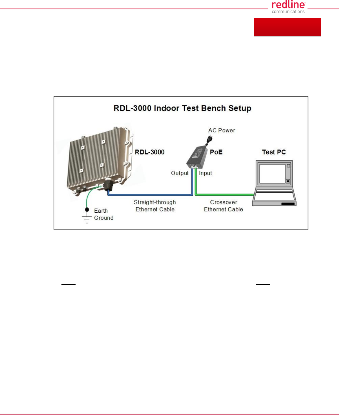
RDL-3000 User Manual
70-00158-01-DRAFT Proprietary Redline Communications © 2010 Page 39 of 142 November 25, 2010
4 Web Interface
4.1 Connecting With a Web Browser
The RDL-3000 can be configured and monitored using a PC equipped with a standard
Web browser (Internet Explorer 6.0 or higher). The following diagram illustrates the
required standard Ethernet Cat-5e cable connection from the RDL-3000 Ethernet port to
the PoE, and the Ethernet Cat-5e crossover cable from the PoE to the PC.
Fig. 24: Web - Connecting a PC to the RDL-3000
Important Notes:
1. The system must be properly grounded to protect against power surges and
accumulated static electricity.
2. When configuring the RDL-3000 in sector controller mode (PMP SC), the RF ports
must be properly terminated to a dummy RF load, or the radio must be disabled
(Radio Enable = Off).
3. This diagram does not illustrate the lightning protection required for outdoors
installation of the RDL-3000 equipment.
Chapter 4
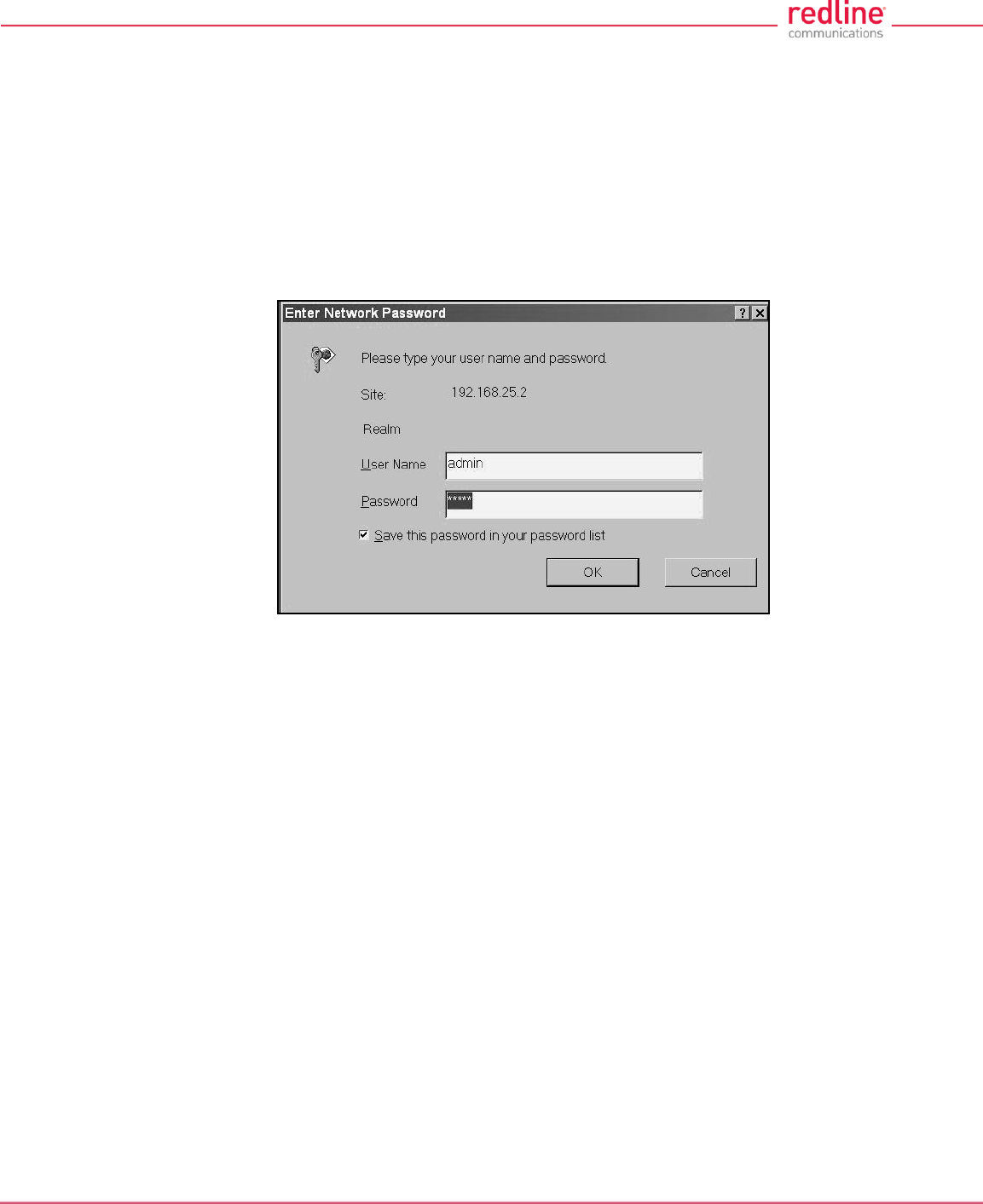
RDL-3000 User Manual
70-00158-01-DRAFT Proprietary Redline Communications © 2010 Page 40 of 142 November 25, 2010
Use the following steps to establish a Web session with the RDL-3000.
1. The IP address and subnet mask of the PC must be on the same subnet as the RDL-
3000. For example:
IP address = 192.168.25.11
Net Mask = 255.255.255.0
2. On the PC, open a browser and enter the unit RDL-3000 IP address. The factory default IP
address is 192.168.25.2.
3. Enter the username and password to login. The factory default username is 'admin', and the
default password is 'admin'.
Fig. 25: Web - Login Screen
4. If the login was successful, the General Information screen will be displayed in the Web
browser.
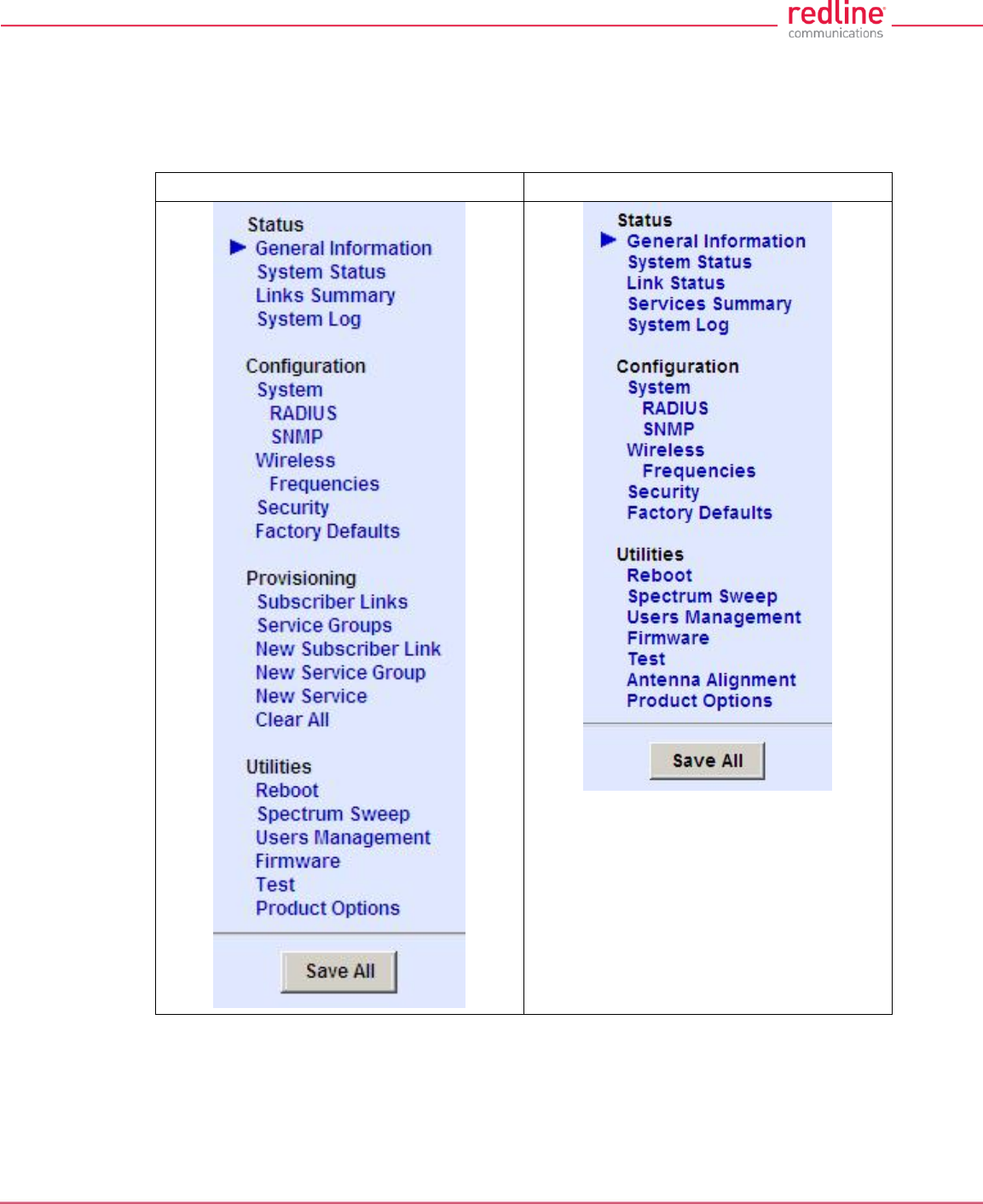
RDL-3000 User Manual
70-00158-01-DRAFT Proprietary Redline Communications © 2010 Page 41 of 142 November 25, 2010
4.2 System Menu
4.2.1 Sector Controller and Subscriber Menus
The following functions are available for configuring and monitoring the RDL-3000.
Sector Controller Menu
Subscriber Menu
Fig. 26: Web - Main Menus for Sector Controller and Subscriber
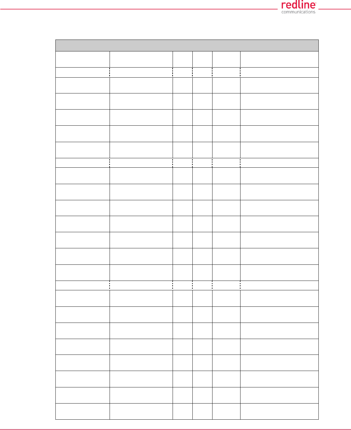
RDL-3000 User Manual
70-00158-01-DRAFT Proprietary Redline Communications © 2010 Page 42 of 142 November 25, 2010
4.2.2 Command and Screen Account Permissions
The following table lists the permissions associated with each group.
Table 4: Web - Screens and User Access
Menu Command
Screen
PMP
SC
PMP
SS
User
Access
Description
Status
General
Information
General Information
√
√
√
View general identification
and configuration.
System Status
System Status
√
√
√
View system, Ethernet,
and wireless statistics.
Links Summary
Subscriber Links
Summary
√
X
√
View all wireless links.
Services
Summary
Subscriber Services
Summary
X
√
√
View all wireless links.
System Log
System Events
√
√
√
View the system status
messages.
Configuration
System
System
Configuration
√
√
View and adjust system,
and network settings.
RADIUS
RADIUS
Configuration
√
√
View and adjust RADIUS
server settings.
SNMP
SNMP Configuration
√
√
View and adjust SNMP
settings.
Wireless
Wireless
Configuration
√
√
View and adjust wireless
settings.
Frequencies
Frequency
Management
√
√
View and adjust RF
scanning lists.
Security
Security
Configuration
√
√
View and adjust
encryption settings.
Factory
Defaults
√
√
Restore factory default
settings. 1
Provisioning
Subscriber
Links
Subscriber Links
√
X
Display all Subscriber
Links.
Link Status
Subscriber Link
Status
√
X
Link
Configuration
Subscriber Link
Configuration
√
X
Service Groups
Service Groups
√
X
√
Display all Service
Groups.
Group Status
Service Group
Status
√
X
Group
Configuration
Service Group
Configuration
√
X
Services
Services
√
X
√
Display all Service
Groups.
Service
Status
Service Status
√
X
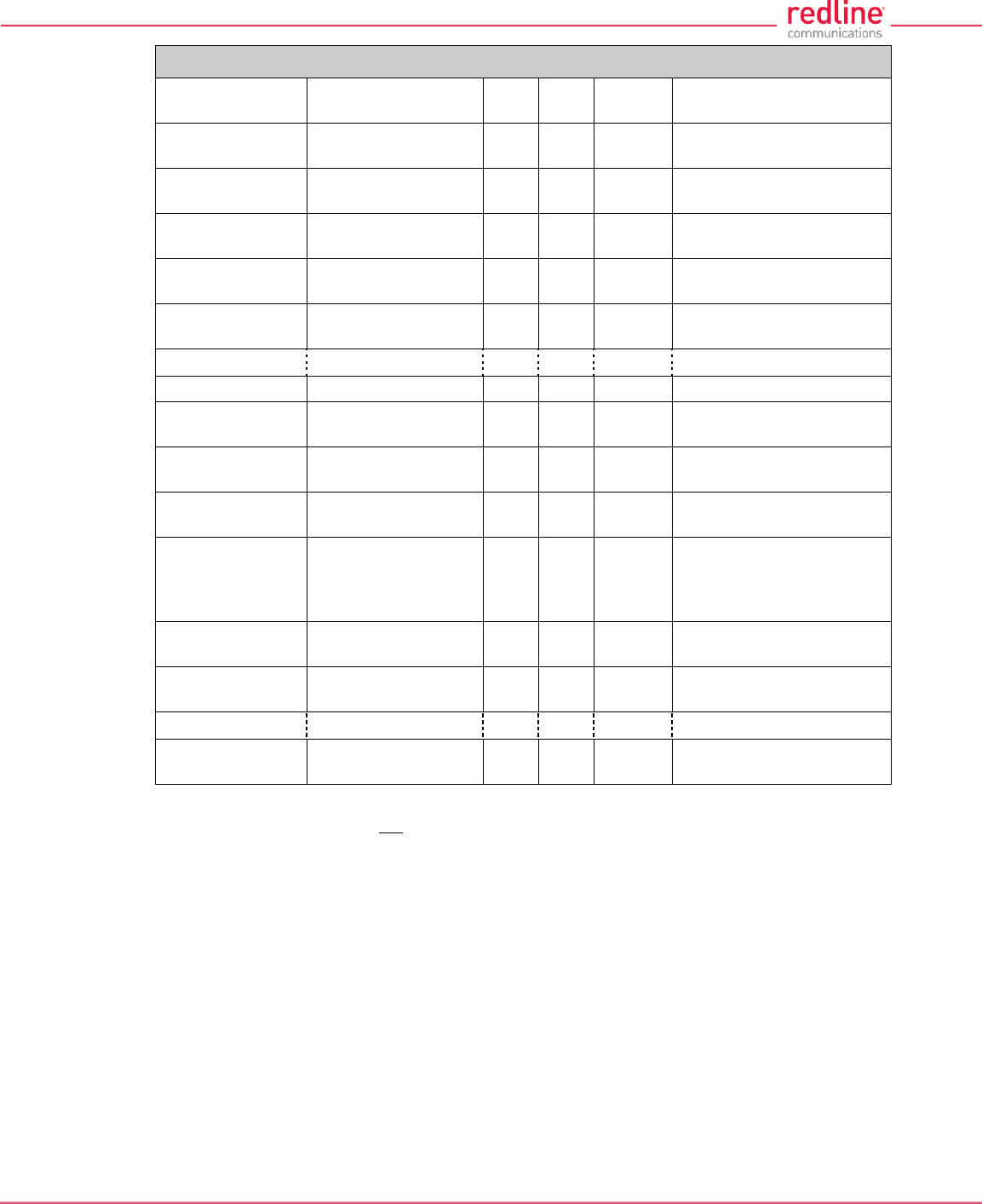
RDL-3000 User Manual
70-00158-01-DRAFT Proprietary Redline Communications © 2010 Page 43 of 142 November 25, 2010
Table 4: Web - Screens and User Access
Menu Command
Screen
PMP
SC
PMP
SS
User
Access
Description
Service
Configuration
Service
Configuration
√
X
New Link
Subscriber Link
Configuration
√
X
Create a new Link.
New Group
Service Group
Configuration
√
X
Create a new Service
Group.
New Service
Service
Configuration
√
X
Create a new Service.
Clear All
√
X
Delete all Links, Service
Groups and Services.
Utilities
Reboot
√
√
Reboot the RDL-3000.
Spectrum
Sweep
Spectrum Sweep
√
√
Scan for interference.
Users
Management
Users Management
√
√
√
Manage user accounts
and passwords.
Firmware
Firmware
Management
√
√
Upload new firmware.
Test
√
√
Test for 5 minutes, and
then restore the last
saved configuration (no
reboot).
Antenna
Alignment
Antenna Alignment
X
√
Display RSSI readings.
Product
Options
Product Options
√
√
View / change the product
options key.
Misc.
Save All
√
√
Save all configuration
changes.
Notes:
1. The following settings are not affected: system name, location, details and contact, frequency
list, SNMP configuration, Idtable.
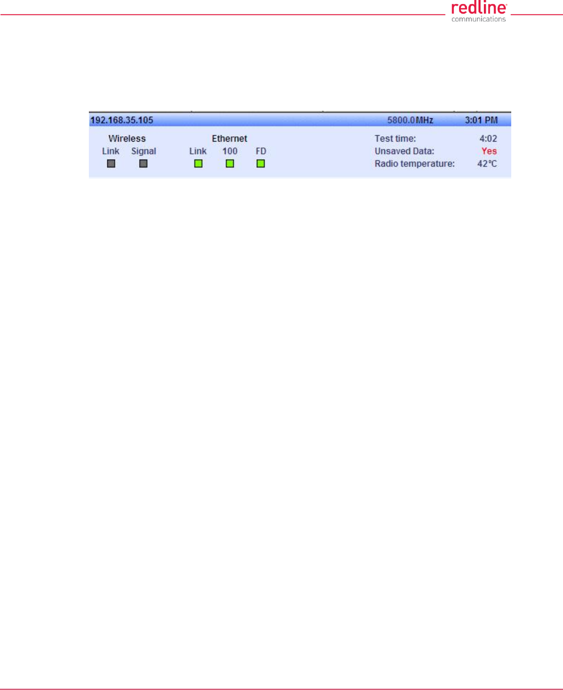
RDL-3000 User Manual
70-00158-01-DRAFT Proprietary Redline Communications © 2010 Page 44 of 142 November 25, 2010
4.3 Dashboard Display
4.3.1 General Information
The dashboard is displayed at the top of all screens. This feature displays a summary of
important operational information including the unit IP address, operating frequency,
time, wireless and Ethernet status, and the radio temperature.
Fig. 27: Web - Dashboard Display
IP Address: IP address of this unit.
Wireless Frequency: RF frequency in use.
Time: Current time obtained from Web browser.
Test time: Visible only when the Test function is active. The last saved configuration is
restored when counter reaches zero (no reboot).
Unsaved Data: Indicates if the running configuration matches the saved configuration.
No: There are no differences between the running and saved configurations.
Yes: There are differences between the running and saved configurations. The current
settings are discarded at the next system rebooted or when the saved configuration is
restored through use of the Test function. Click Save All in the main menu to save the
current running configuration. This configuration will be restored on power-up, reboot, or
the end of a test cycle.
Saving: The system is saving the runtime parameters to non-volatile RAM.
Radio Temperature: Internal temperature of the radio.
4.3.2 Wireless Leds
These LED indicators provide a summary of the wireless status.
Link LED
The wireless Link LED lights solid green under the following conditions:
Sector Controller: Wireless link is established to one or more subscribers.
Subscriber: Wireless link is established to the sector controller.
Signal LED
The wireless Signal LED operation is based on the Adaptive Modulation and Uncoded
Burst Rate (UBR) settings for each subscriber. These fields are on the Subscriber Link
Configuration screen.
Adaptive Modulation Enabled: LED lights solid green when the wireless link is
operating at the rate equal to the UBR setting for this link. The LED blinks when the link
is operating at a rate lower than the UBR setting.
Adaptive Modulation Disabled: LED lights solid green when the wireless link is
established.
4.3.3 Ethernet LEDs
These LED indicators provide a summary of the Ethernet port status.

RDL-3000 User Manual
70-00158-01-DRAFT Proprietary Redline Communications © 2010 Page 45 of 142 November 25, 2010
Link LED
The Ethernet Link LED lights solid green when there is an Ethernet connection and no
traffic, and blinks when traffic is detected.
100 LED
The Ethernet 100 LED lights solid green when the Ethernet port is operating at 100 Mb/s
and the LED is off when operating at 10 Mb/s.
FD LED
The FD LED lights solid green when the Ethernet connection is operating in full duplex
mode and blinks when collisions are detected on the Ethernet port.
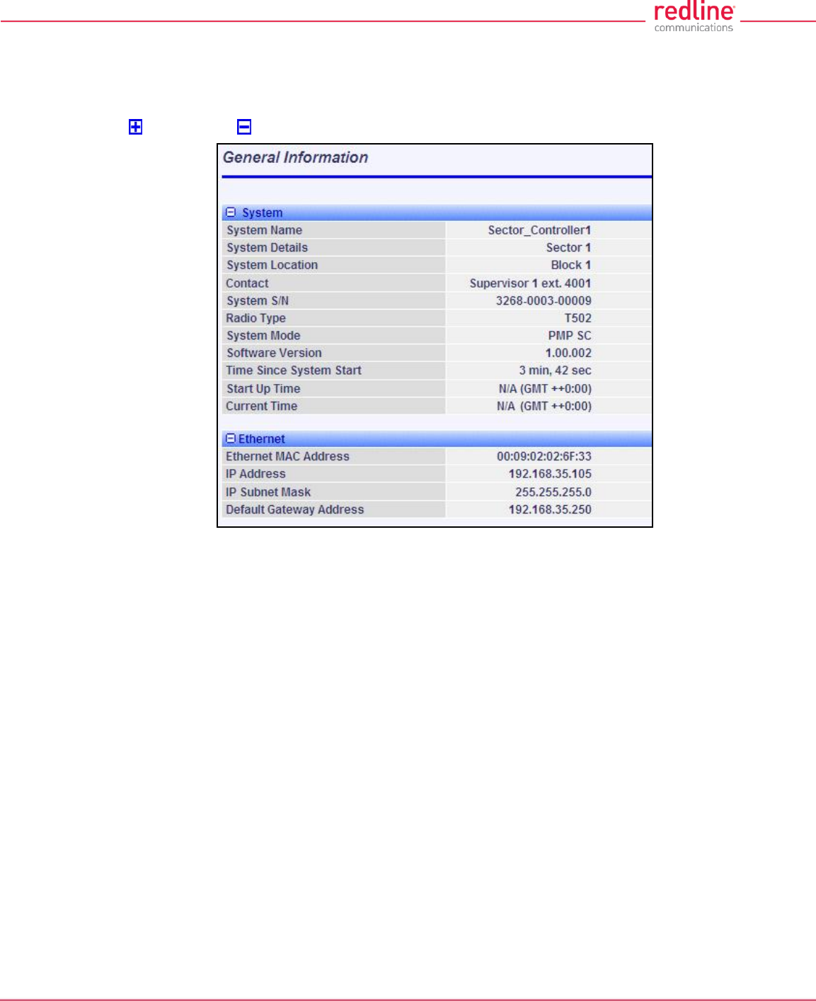
RDL-3000 User Manual
70-00158-01-DRAFT Proprietary Redline Communications © 2010 Page 46 of 142 November 25, 2010
4.4 Status Screens
4.4.1 General Information
The General Information screen displays system and the Ethernet interface details. Click
to expand or to hide fields.
Fig. 28: Web - General Information Screen
System
System Name: User-assigned name for this RDL-3000.
System Details: User-assigned system details information.
System Location: User-assigned system location information.
Contact: User-assigned contact information.
System SN: Displays the unique serial number identifying this unit.
Radio Type: Displays the factory installed radio type. Refer to section 8.1 System
Specifications.
System Mode: Operating mode of this unit:
PMP SC: Operating as a sector controller, the RDL-3000 begins transmitting
automatically, sends poll messages to locate and register remote subscribers, and
negotiates operating settings for each subscriber.
PMP SS: Operating as a subscriber, the RDL-3000 monitors the selected channel(s)
until polled by the sector controller.
Firmware Version: Displays the firmware version in use.
Time Since System Start: Elapsed time since the last system reboot/power-cycle.
Start Up Time: Time and date of the last system reboot/powered-cycle.
Current Time: Current time on the RDL-3000 internal clock. The time may be unavailable if
the SNTP (time server) feature is disabled. The screen will display 'N/A (GMT +0:00'.

RDL-3000 User Manual
70-00158-01-DRAFT Proprietary Redline Communications © 2010 Page 47 of 142 November 25, 2010
Ethernet
Ethernet MAC Address: MAC address of the network interface on this unit.
IP Address: Network IP address for this unit.
IP Subnet Mask: Network IP subnet mask.
Default Gateway Address: Network IP address of the default router or gateway.
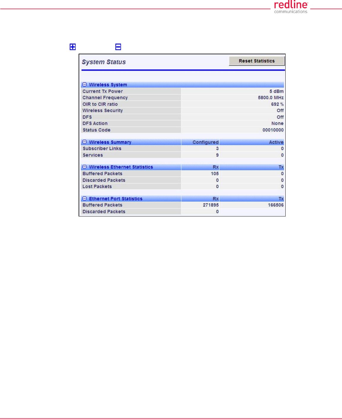
RDL-3000 User Manual
70-00158-01-DRAFT Proprietary Redline Communications © 2010 Page 48 of 142 November 25, 2010
4.4.2 System Status
Click System Status in the main menu to view information about the wireless interface
and Ethernet port. This screen is identical for the sector controller and subscriber units.
Click to expand or to hide fields.
Fig. 29: Web - SC System Status Screen
Wireless System
Current Tx Power: The current transmit power level.
Channel Frequency: The RF channel in-use.
OIR to CIR Ratio: (SC only) This value indicates if the system can meet the current
scheduling requirements. A positive value indicates that surplus bandwidth is available.
Wireless Security: Status of the wireless security selection.
Off - No wireless security.
On - Data sent over the wireless interface is encrypted.
DFS: Status of the DFS function.
Off: The DFS function is disabled.
On: DFS function is activated. See DFS Action below.
DFS Action: The avoidance action to be taken when radar signals are detected. All DFS
actions are recorded in the event log.
None: The DFS feature is disabled.
Tx Off: Radio transmitter is disabled for 30 minutes.
Chg Freq: Radio transmitter is changed to a different RF frequency.
Status Code: Code indicating the status of the RDL-3000 system. Code '0000 0000'
indicates normal operation. Refer to section 6.2: Status Codes on page 119.
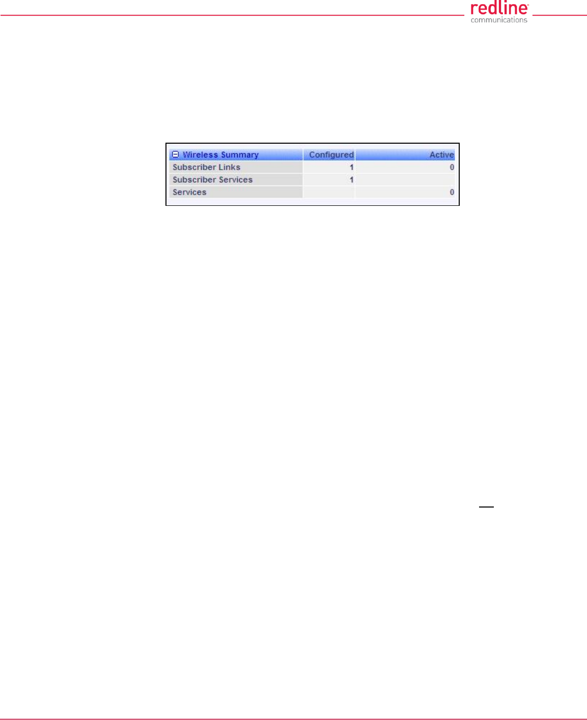
RDL-3000 User Manual
70-00158-01-DRAFT Proprietary Redline Communications © 2010 Page 49 of 142 November 25, 2010
Wireless Summary
Subscriber Links: Status of the wireless links to subscribers.
Configured: Number of provisioned Subscriber Links.
Active: Number of subscribers that are online (registered with sector controller).
Subscriber Services: (Subscriber only) Status of the Subscriber Services for this
subscriber.
Configured: Number of provisioned Services.
Fig. 30: Web - SS System Status Screen
Services: Status of the Services for all subscribers.
Configured: (SC only) Number of provisioned Services.
Active: Number of active Services (subscriber are active).
Wireless Ethernet Statistics
Buffered Packets: Number of packets successfully processed over the wireless interface,
excluding discarded and errored packets.
Rx: Received wireless packets.
Tx: Transmitted wireless packets.
Discarded Packets: Number of packets discarded by the local unit.
Rx: Received wireless packets discarded (buffer overflow).
Tx: Transmitted wireless packets discarded by the local unit due to errors (e.g., buffer
overflow, or unacknowledged by remote end unit).
Lost Packets: Total number of packets containing errors (e.g., CRC).
Rx: Received wireless packets with errors.
Tx: Transmitted wireless packets with errors detected by remote end unit.
Ethernet Port Statistics
Buffered Packets: Packets processed through the Ethernet port. Total does not include
discarded or errored packets.
Rx: Number of ingress packets received on the Ethernet port.
Tx: Number or egress packets transmitted on the Ethernet port.
Discarded Packets: Total number of packets discarded due to buffer overflow.
Rx: Received packets discarded due to errors (e.g., CRC or buffer overflow).
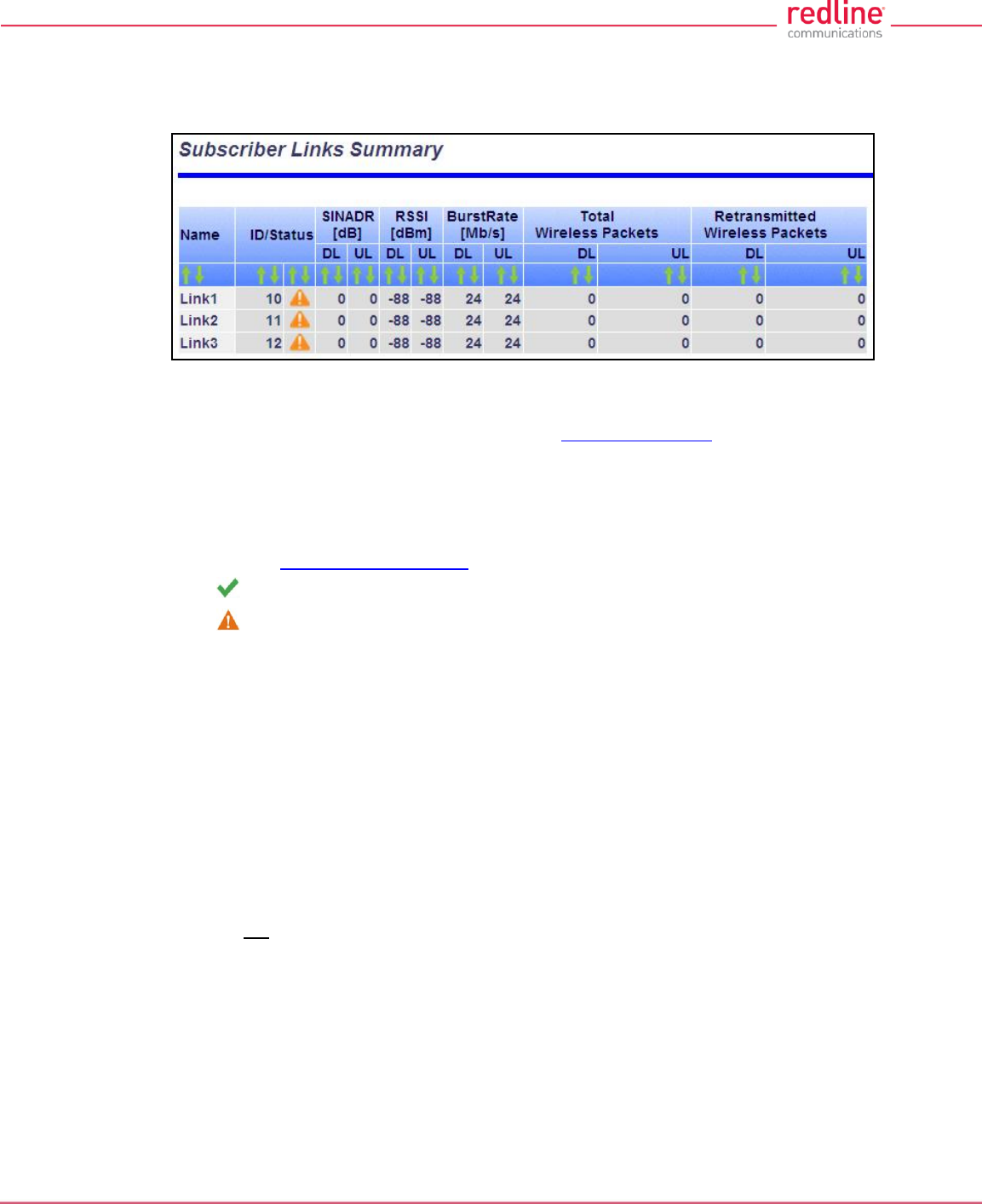
RDL-3000 User Manual
70-00158-01-DRAFT Proprietary Redline Communications © 2010 Page 50 of 142 November 25, 2010
4.4.3 Subscriber Links Summary Screen (SC Only)
Click Links Summary in the main menu (SC) to view the status of all wireless links. This
screen is available only on subscriber units.
Fig. 31: Web - Subscriber Links Summary Screen
Name: Operator-assigned name for wireless Links and related Services. Click on a
Subscriber Link name (e.g., Link1) to display the Link Configuration screen
ID/Status: Subscriber Link identifier and status indicator.
ID: A unique numeric ID generated automatically when the Subscriber Link was
created. This value is required when using the CLI interface to modify Link settings.
Status: Graphic indication of the status of this link or Service. Click on the symbol to
display the Subscriber Link Status screen.
The link or Service is available.
The link or Service is unavailable (offline or disabled).
SINADR [dB]: Ratio of the average RF signal strength to interference, noise, and distortion.
DL: SINADR reported by the remote end unit.
UL: Received signal strength to noise measured by this unit.
RSSI [dBm]: Received signal strength indicator.
DL: RSSI reported by the remote end unit.
UL: Received signal strength measured by this unit.
Burst Rate [Mb/s]: The current uplink and downlink uncoded burst rate for the link.
DL: Operator-assigned maximum downlink burst rate setting.
UL: Operator-assigned maximum uplink burst rate setting.
Total Wireless Packets: Total packets successfully processed over the wireless interface.
Total does not include discarded or errored packets.
DL: Total packets transmitted over the wireless interface.
UL: Total packets received over the wireless interface.
Retransmitted Wireless Packets: Total number of wireless packets that have been
retransmitted over the wireless interface.
DL: Total packets retransmitted over the wireless interface.
UL: Total packets retransmitted by the remote end.
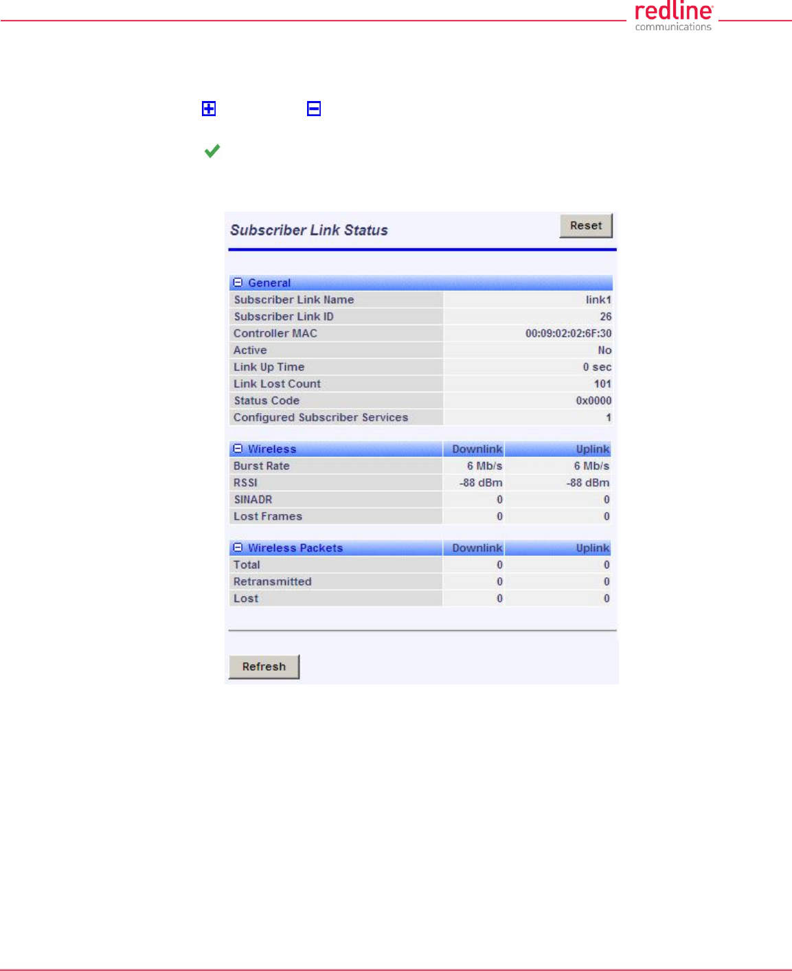
RDL-3000 User Manual
70-00158-01-DRAFT Proprietary Redline Communications © 2010 Page 51 of 142 November 25, 2010
4.4.4 Subscriber Link Status
The Subscriber Link Status screen provides a summary view of the status of the
selected Subscriber Link. This screen is identical for the sector controller and subscriber
units. Click to expand or to hide fields.
SC: Click Provisioning->Subscriber Links in the main menu and then click on the Link
status (e.g., ) to display this screen.
SS: Click Link Status in the main menu to view the status of the wireless link for this
subscriber.
Fig. 32: Web - Subscriber Link Status Screen
General
Subscriber Link Name: User-assigned name for this link.
Subscriber Link ID: Unique number identifying this link.
Subscriber MAC: MAC Address of the subscriber.
Active: Indicates if wireless link is operational (Active=YES).
Link Up Time: Total time the wireless link has been operational.
Link lost Count: Number of times link has been out of service.
Status Code: Code indicating the condition of the RDL-3000 system.
Configured Subscriber Services: The number of Services provisioned on this link.

RDL-3000 User Manual
70-00158-01-DRAFT Proprietary Redline Communications © 2010 Page 52 of 142 November 25, 2010
Wireless
The following statistics are displayed for the downlink and uplink.
Burst Rate: The current uncoded burst rate for the link.
RSSI: Received signal strength indicator.
SINADR: Average signal to interference, noise, and distortion ratio.
Lost Frames: Number of frames lost.
Wireless Packets
The following statistics are displayed for the downlink and uplink.
Total: Total packets successfully processed over the wireless interface. Total does not
include discarded or errored packets.
Retransmitted: Total number of wireless packets that have been retransmitted over the
wireless interface.
Lost: Total packets discarded by the local system due to errors.
SINADR [dB]: Ratio of the average RF signal strength to interference, noise, and distortion.
DL: SINADR reported by the remote end unit.
UL: Received signal strength to noise measured by this unit.
RSSI [dBm]: Received signal strength indicator.
DL: RSSI reported by the remote end unit.
UL: Received signal strength measured by this unit.
Burst Rate [Mb/s]: The current uplink and downlink uncoded burst rate for the link.
DL: Operator-assigned maximum downlink burst rate setting.
UL: Operator-assigned maximum uplink burst rate setting.
Controls
Refresh: Click to update displayed statistics counters.
Reset: Click to reset displayed statistics counters.
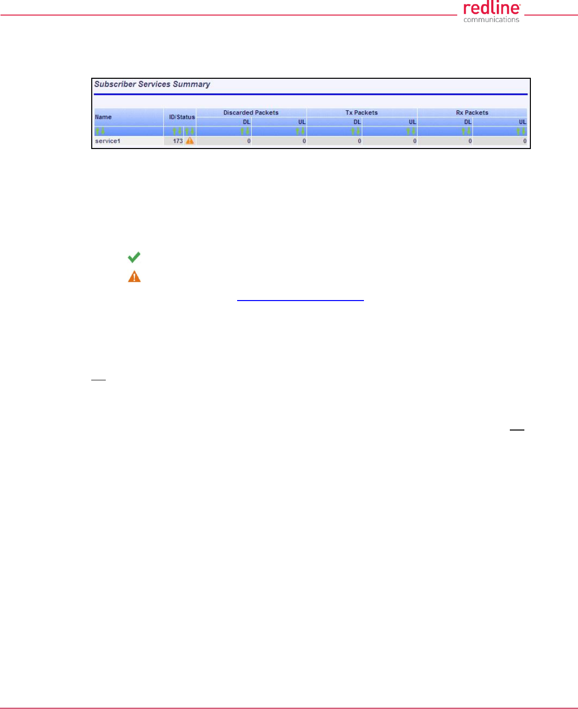
RDL-3000 User Manual
70-00158-01-DRAFT Proprietary Redline Communications © 2010 Page 53 of 142 November 25, 2010
4.4.5 Subscriber Services Summary Screen (SS Only)
Click Services Summary in the main menu (SS) to view the status of all Services on
this subscriber. This screen is available only on the subscriber unit.
Fig. 33: Web - Services Summary Screen
Name: Operator-assigned name for Service.
ID/Status: Service identifier and status indicator.
ID: A unique numeric ID generated automatically when the Service was created. This
value is required when using the CLI interface to modify Services settings.
Status: Graphic indication of the status of this link or Service.
The link or Service is available.
The Link or Service is unavailable (offline or disabled).
Click the status to display the Subscriber Service Status screen.
Discarded Packets: Total number of packets discarded by the local system due to errors.
UL: Received wireless packets discarded.
DL: Transmitted wireless packets discarded by remote end unit.
Tx Packets: Total packets successfully transmitted over the wireless interface. Total does
not include discarded or errored packets.
DL: Total packets sector controller has reported transmitting to this subscriber.
UL: Total packets subscriber has transmitted to sector controller.
Rx Packets: Total packets successfully received over the wireless interface. Total does not
include discarded or errored packets.
DL: Total packets subscriber has received from sector controller.
UL: Total packets sector controller has reported receiving from subscriber.
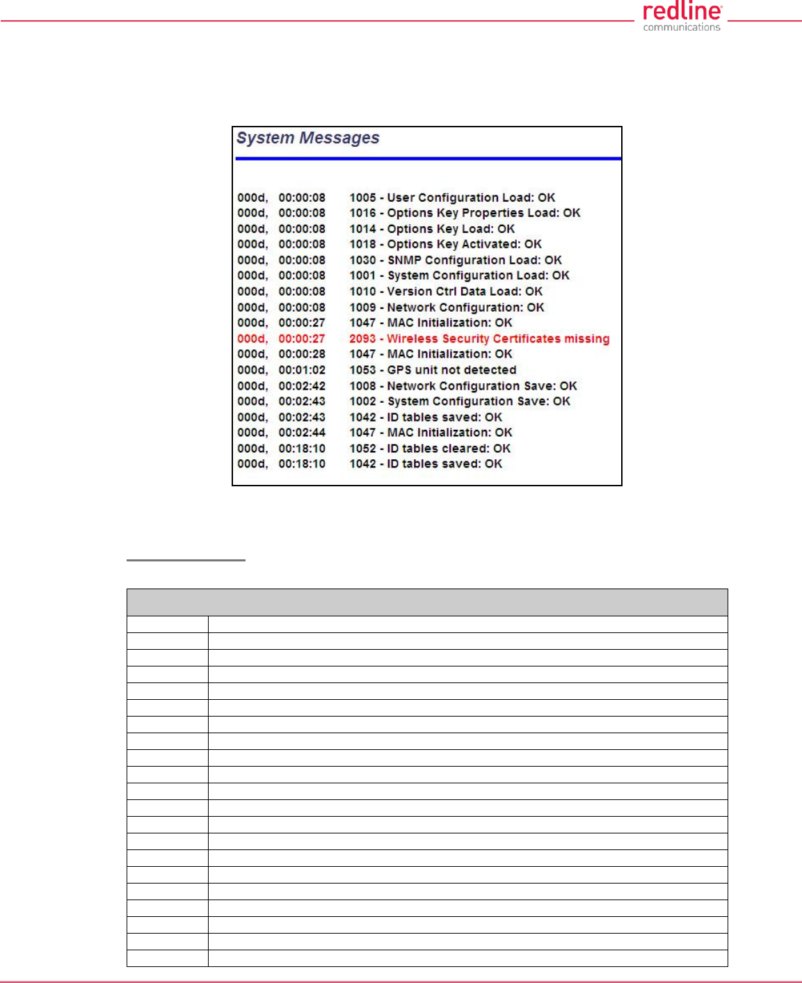
RDL-3000 User Manual
70-00158-01-DRAFT Proprietary Redline Communications © 2010 Page 54 of 142 November 25, 2010
4.4.6 System Messages (Log)
Click System Log in the main menu to view the system activity and error messages
recorded by the RDL-3000. This screen is identical for the sector controller and
subscriber units.
Fig. 34: Web - System Log Messages
Clear Log: Click to erase all messages from the system log file.
Event Messages
The following table provides a brief description of the key system messages.
Table 5: Web - System Log Messages
Event ID
Event Description
1001
System Configuration Load: OK
1002
System Configuration Save: OK
1003
EEPROM Directory Load: OK
1004
EEPROM Directory Save: OK
1005
User Configuration Load: OK
1006
User Configuration Save: OK
1007
Network Configuration Load: OK
1008
Network Configuration Save: OK
1009
Network Configuration: OK
1010
Version Ctrl Data Load: OK
1011
Version Ctrl Data Save: OK
1012
System Description Load: OK
1013
System Description Save: OK
1014
Options Key Load: OK
1015
Options Key Save: OK
1016
Options Key Properties Load: OK
1017
Options Key Properties Save: OK
1018
Options Key Activated: OK
1019
Data server started: OK
1021
Upgrade: OK

RDL-3000 User Manual
70-00158-01-DRAFT Proprietary Redline Communications © 2010 Page 55 of 142 November 25, 2010
Table 5: Web - System Log Messages
Event ID
Event Description
1023
Firmware configuration: OK
1026
Factory Data Save: OK
1029
HTTP(User Mgm): Chg User Attributes: OK
1030
SNMP Configuration Load: OK
1031
SNMP Configuration Save: OK
1032
SNTP: Time received: OK
1033
DFS: Event Detected
1033
MAC Initialization: OK
1034
DFS: Event Detected
1035
ID deleted: OK
1036
Restart freq scan (RSSI)
1037
Restart freq scan (TimeOut)
1038
Reg Req (step 1)
1039
Reg Req (step 2
1040
Reg Req (step 2)
1041
Restart freq scan (act links)
1042
ID tables saved: OK
1043
ID defined: OK
1044
ID tables not changed: OK
1045
ID modified: OK
1046
RF frequency validation: OK
2001
System Configuration Load: Error
2002
System Configuration Save: Error
2003
EEPROM Directory Load: Error
2004
EEPROM Directory Save: Error
2005
User Configuration Load: Error
2006
User Configuration Save: Error
2007
Network Configuration Load: Error
2008
Network Configuration Save: Error
2009
Network Configuration: Error
2010
Version Ctrl Data Load: Error
2011
Version Ctrl Data Save: Error
2012
System Description Load: Error
2013
System Description Save: Error
2014
Options Key Load: Error
2015
Options Key Save: Error
2016
Options Key Properties Load: Error
2017
Options Key Properties Save: Error
2018
Options Key Activated: Error
2019
No Options Key
2020
Fail to start the data server
2021
Data server
2022
Data server
2023
Upgrade client start: Error
2024
Upgrade in progress
2025
Upgrade: FAIL
2026
Upgrade: Error
2028
Factory Data Corrupted (use fallback values)
2028
TFTP: Error
2029
Firmware configuration: Error
2031
Factory Data Save: Error
2034
HTTP(User Mgm): Invalid password
2035
HTTP(User Mgm): Invalid User

RDL-3000 User Manual
70-00158-01-DRAFT Proprietary Redline Communications © 2010 Page 56 of 142 November 25, 2010
Table 5: Web - System Log Messages
Event ID
Event Description
2036
HTTP(User Mgm): Chg User Attributes: Error
2037
SNMP Configuration Load: Error
2038
SNMP Configuration Save: Error
2039
Invalid Options Key
2039
SNTP: Time received: Error
2040
MAC Initialization: Error
2041
MAC Busy
2042
ID database corrupted
2043
Invalid ID
2044
Max. ID number reached
2045
Int Procs programming: Error
2046
Int Procs start: Error
2047
ID action not possible
2048
ID validation: Error
2049
HW validation: Error
2050
FTP: Error
2051
WS: Timeout (WS_SEND_SESSION_REQ)
2063
SSH RSA KEY missing, using default key
2064
SSH DSA KEY missing, using default key
2065
SSL Certificate missing, using default one
2066
SSL KEY missing, using default one
2070
Pre Shared Key ERROR
2071
Authentication Packet Validation ERROR
2072
Encryption Key Validation ERROR
2073
Signature Validation ERROR
2074
Certificate Validation ERROR
2075
RNG self test ERROR
2076
DSA pair wise test failed
2077
RNG self test failed
2078
TDES self test failed
2079
AES self test failed
2080
SHA self test failed
2081
HMAC self test failed
2082
RSA self test failed
2083
DES self test failed
2084
MAC AES self test failed
2086
Upgrade image validation: ERROR
2087
Upgrade ERROR: image save
2088
SSH RSA KEY missing, using generated key
2089
SSH DSA KEY missing, using generated key
2090
Test not executed when FIPS mode changed
2091
The options key expires in less than 6 days
2092
SSL Certificate missing, HTTPS disabled
2093
Wireless Security Certificates missing
2094
Firmware validation: ERROR (%s)
2095
Image validation: ERROR
2099
Unknown Message
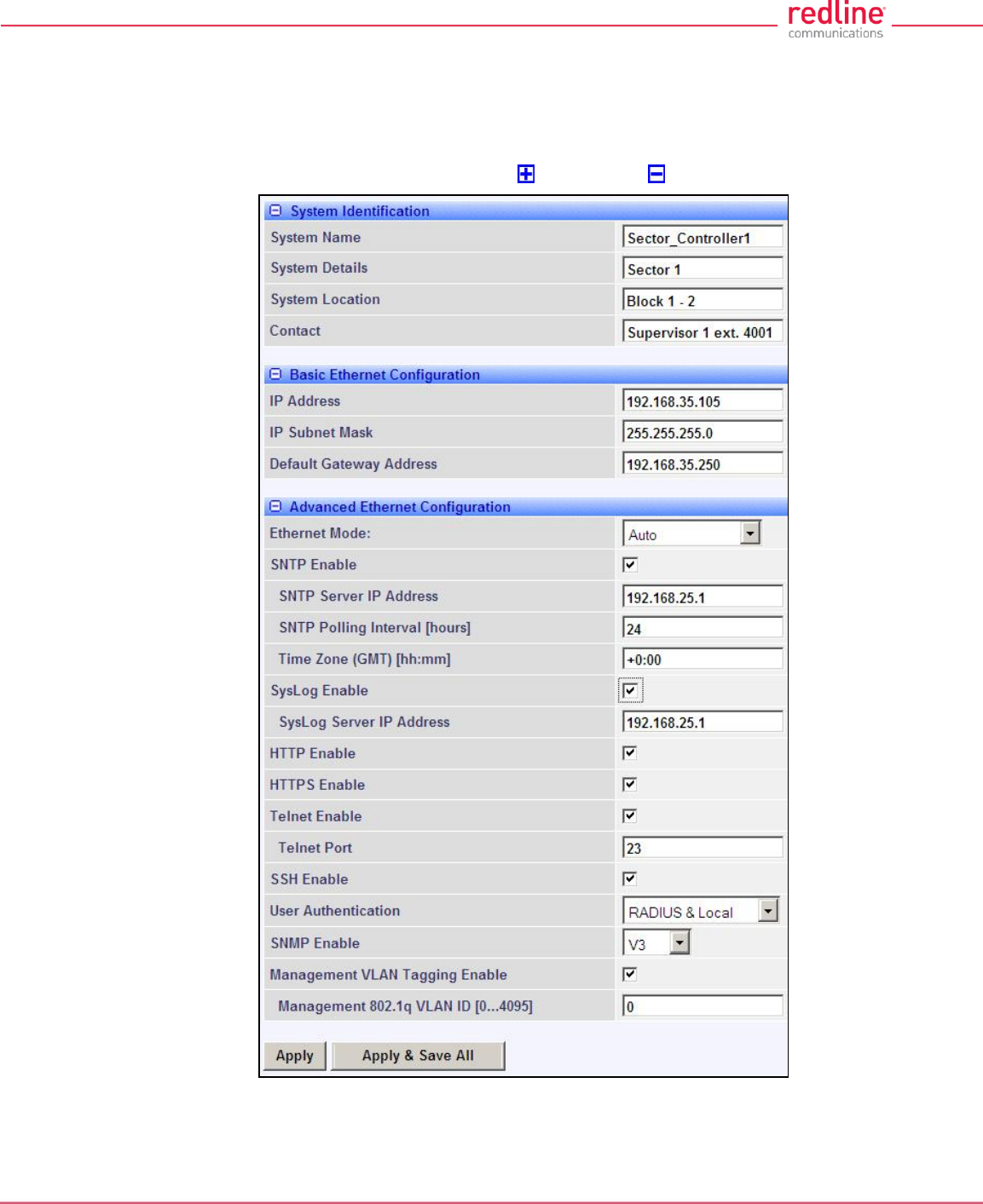
RDL-3000 User Manual
70-00158-01-DRAFT Proprietary Redline Communications © 2010 Page 57 of 142 November 25, 2010
4.5 Configuration Screens
4.5.1 System Screen
Click Configuration-> System in the main menu to view and adjust configuration
settings for system identification and Ethernet settings. This screen is identical for the
sector controller and subscriber units. Click to expand or to hide fields.
Fig. 35: Web - Config - PMP SC System Configuration Screen
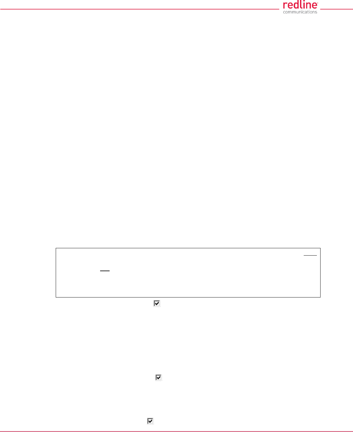
RDL-3000 User Manual
70-00158-01-DRAFT Proprietary Redline Communications © 2010 Page 58 of 142 November 25, 2010
System Identification
System Name: Enter the name for this RDL-3000. The system name may be up to thirty
alpha-numeric characters including a-z, A-Z, 0-9, dash (-), and underscore (_).
System Details: Enter additional descriptive details about this RDL-3000. The system
details may be up to thirty alpha-numeric characters including a-z, A-Z, 0-9, dash (-), and
underscore (_).
System Location: Enter additional descriptive details about this RDL-3000. The system
location information may be up to thirty alphanumeric characters including a-z, A-Z, 0-9,
dash (-), and underscore (_).
Contact: Enter additional descriptive details about this RDL-3000. The contact
information may be up to thirty alpha-numeric characters including a-z, A-Z, 0-9, dash (-
), and underscore (_).
Basic Ethernet Configuration
IP Address: Enter the IP address for this RDL-3000. The IP address is routable both
through the Ethernet port and over the wireless interface.
IP Subnet Mask: Enter the IP subnet mask.
Default Gateway Address: Enter the IP address of the default gateway or router on the
Ethernet segment connected to the RDL-3000 Ethernet port.
Advanced Ethernet Configuration
Ethernet Mode: Select the operating mode of the Ethernet port.
Auto - Automatically negotiate the connection speed and duplex.
10Mbps HD - Operate at 10Base-T half-duplex only.
10Mbps FD - Operate at 10Base-T full duplex only.
100Mbps HD -.Operate at 100Base-T half-duplex only.
100Mbps FD - Operate at 100Base-T full duplex only.
Important: The auto-negotiate function works correctly only when both
communicating Ethernet devices are configured for auto-negotiate. The auto-negotiate
feature does not detect the speed and duplex of Ethernet equipment operating at a
fixed speed and duplex. Duplex mismatches may result in an unexpected loss of
communications. It is recommended to set the Ethernet ports to operate at a fixed
speed of 100Base-T using full duplex.
SNTP Enable: Check this box to enable the SNTP protocol support. This feature
allows RDL-3000 systems to time-stamp log messages using a network time server.
When enabled, you must enter the network address of the SNTP server in the SNTP
Server IP Address field.
When SNTP is enabled, the following additional configuration fields are visible:
SNTP Server IP Address: Enter the network address of the SNTP server.
SNTP Polling Interval [hours]: Enter the SNTP polling interval (hours).
Time Zone (GMT) [hh:mm]: Enter the hours offset from GMT for this time zone.
Syslog Enable: Check this box to enable the Syslog protocol support. This feature
allows RDL-3000 log messages to be saved in a central repository. When enabled, you
must enter the network address of the Syslog server in the Syslog Server IP Address
field. When Syslog is enabled, the following additional configuration field is visible:
Syslog Server IP Address: Enter the network address of the Syslog server.
HTTP Enable: Check this box to enable the HTTP (Web) interface.

RDL-3000 User Manual
70-00158-01-DRAFT Proprietary Redline Communications © 2010 Page 59 of 142 November 25, 2010
HTTPS Enable: Check this box to enable HTTPS operation (secure/encrypted Web
session). Refer to page 126 for a complete description of this feature.
Telnet Enable: Check this box to enable a Telnet access (CLI) to the RDL-3000.
When Telnet is enabled, the following additional configuration field is visible:
Telnet Port: Enter Telnet port address (default is 23).
SSH Enable: Check this box to enable SSH operation (secure/encrypted CLI). Refer to
page 126 for a complete description of this feature.
User Authentication: The RDL-3000 supports a local authorization policy and secure
centralized authentication management using a RADIUS server. At least one policy is
always enabled, and both may be enabled to operate together.
The RDL-3000 can be configured for the following authentication modes:
Local Only: Use only RDL-3000 local authentication functions (default). Local
authentication uses user names and password information managed by the RDL-
3000. This method is supported by all versions of RDL-3000 firmware.
RADIUS Only: Use only RADIUS for user authentication.
An access request to the RDL-3000 is forwarded to the RADIUS server. At least one
RADIUS server must be enabled in this mode. The configuration can be done
through the CLI or HTTP. The following parameters must be specified for each
RADIUS server (primary server and optional backup server):
Local + RADIUS: Both methods of user authentication are enforced.
When Local + RADIUS or RADIUS Only is selected, click on the main menu item
RADIUS to display the RADIUS Configuration screen.
Note: When user authentication is set to RADIUS Only or Local + RADIUS, the
authorization data is retrieved from the RADIUS server at 10-minute intervals. For
example, if a user's authorization is changed on the RADIUS server, it may require up to
ten minutes before the RDL-3000 is updated with the new information.
SNMP Enable: Select the version of Simple Network Management Protocol (SNMP).
The SNMP protocol allows an application to interrogate information and change enabled
fields within the RDL-3000 Management Information Base (MIB).
none: SNMP is disabled.
v2: Supports SNMP v1 and v2c commands.
v3: Supports SNMP v3 exclusively. SNMP v1 and SNMP v2c commands not
accepted and an authorization policy is enforced.
When SNMP is enabled, click on the main menu item Configuration: SNMP to display
the SNMP Configuration screen.
Management VLAN Tagging Enable: Control the VLAN tagged management function.
Disabled ( ): There are no restrictions for management traffic.
Enabled ( ): This unit can be managed only using VLAN traffic tagged with the value
specified in the Mgmt. VID field.
On all PMP systems, over-the-air management is possible only after creating a Service
Group for device management and adding a Service for each subscriber. For installation
and setup, it is recommended to use Pass Through settings for this group and member
Service for each subscriber. Set appropriate CIR and priority values to ensure that
management traffic has adequate priority and bandwidth during system operation.
When Management VLAN Tagging is enabled, the following additional configuration field
is visible:
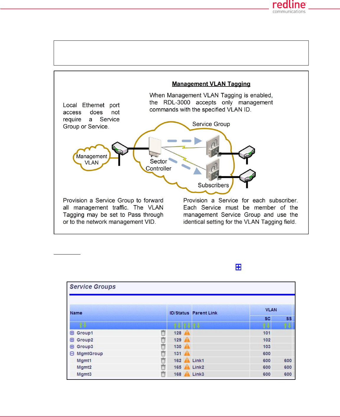
RDL-3000 User Manual
70-00158-01-DRAFT Proprietary Redline Communications © 2010 Page 60 of 142 November 25, 2010
Management 802.1Q VLAN ID [0...4095]: Enter the management VLAN ID. When
Management VLAN Tagging Enable is selected, the system recognizes only
management commands where the Ethernet packet has this VLAN ID.
Important: If the Management VLAN Tagging feature is required, it is recommended
to test the VLAN connectivity before activating this function. Otherwise, the RDL-3000
unit may become unmanageable require a long reset operation to recover control.
Fig. 36: Web - VLAN Tagged Management
Example
In the following example, the network management VLAN ID=600. Identical settings are
used on the Service Group and each subscriber Service. Click to display the Services
associated with each Service Group.
Fig. 37: Web - VLAN Tagged Management Example

RDL-3000 User Manual
70-00158-01-DRAFT Proprietary Redline Communications © 2010 Page 61 of 142 November 25, 2010
4.5.2 RADIUS Setup
When Radius or Local + RADIUS is checked, click Configuration->System->RADIUS in
the main menu to display the RADIUS Configuration screen. Identical screens are used
for the sector controller and subscriber units. Click to expand or to hide fields.
Fig. 38: Web - RADIUS Configuration Screen
The following fields are provided for the primary and secondary RADIUS server:
Server Enable: Control the RADIUS server mode.
Disabled ( ):.Do not use the Primary/Secondary RADIUS server.
Enabled ( ): Use the Primary/Secondary RADIUS server for user authentication.
Server IP Address: RADIUS server IP address.
Server Auth-port: Listening port address on RADIUS server (default port is 1812).
Shared secret: Password for RADIUS server. Must conform to security policy.
Request retries: Maximum number for attempts to contact target RADIUS server.
Request time-out: Time to wait for response from RADIUS server (seconds).
When using a FreeRadius server, the following files must be modified on the RADUIS
server platform. See the RADIUS documentation for additional operating details.
Table 6: Web - Required FreeRadius Files
Define RDL-3000 client.
clients.conf
client 192.168.0.0/16 {secret = secret shortname = RDL3000 }
Add an admin account
users.conf
admuser : Auth-Type := Local, User-Password == "abc"
Service-Type = Administrative-User
Add user account
users.conf
usrjoe: Auth-Type := Local, User-Password == "pass"
Service-Type = NAS-Prompt-User
Reject an account.
users.conf
lameuser: Auth-Type := Reject
Reply-Message = "Account has been disabled."
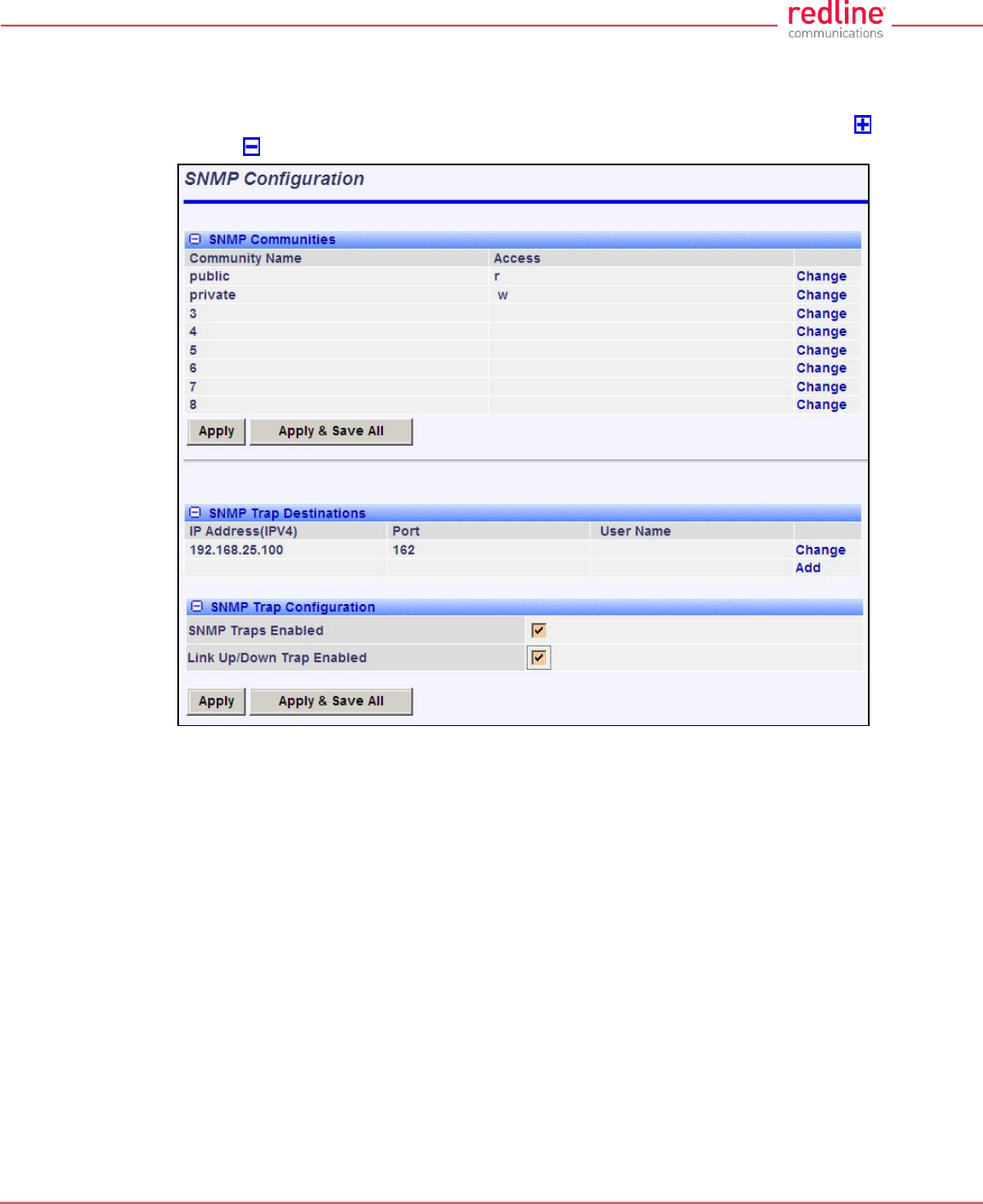
RDL-3000 User Manual
70-00158-01-DRAFT Proprietary Redline Communications © 2010 Page 62 of 142 November 25, 2010
4.5.3 SNMP Configuration
Click Configuration->System->SNMP in the main menu to display the SNMP
Configuration screen. Use this screen to view and modify all SNMP related parameters.
The SNMP screens are identical for the sector controller and subscriber units. Click to
expand or to hide fields.
Fig. 39: Web - SNMP Configuration Screen
SNMP Community Settings
Use this section of the screen to manage the SNMP community settings. The RDL-3000
supports up to eight separate community strings. Each community name is assigned
specific access rights (read/write). The 'public' and 'private' community strings are
default access values and should be changed to secure system access.
Community Name: SNMP community name for this entry.
Access: Access permissions for this entry.
None: No access permissions for this entry.
Read: Read access permission only for this entry. Deny write permission.
Write: Write access permission only for this entry. Deny read permission.
Read&Write: Read and write access permission for this entry.
Change: Click to modify the existing SNMP community string.
Add: Click to add a new SNMP community string. Up to eight strings may be entered.
Apply: Click to activate the SNMP Community settings displayed on this screen.
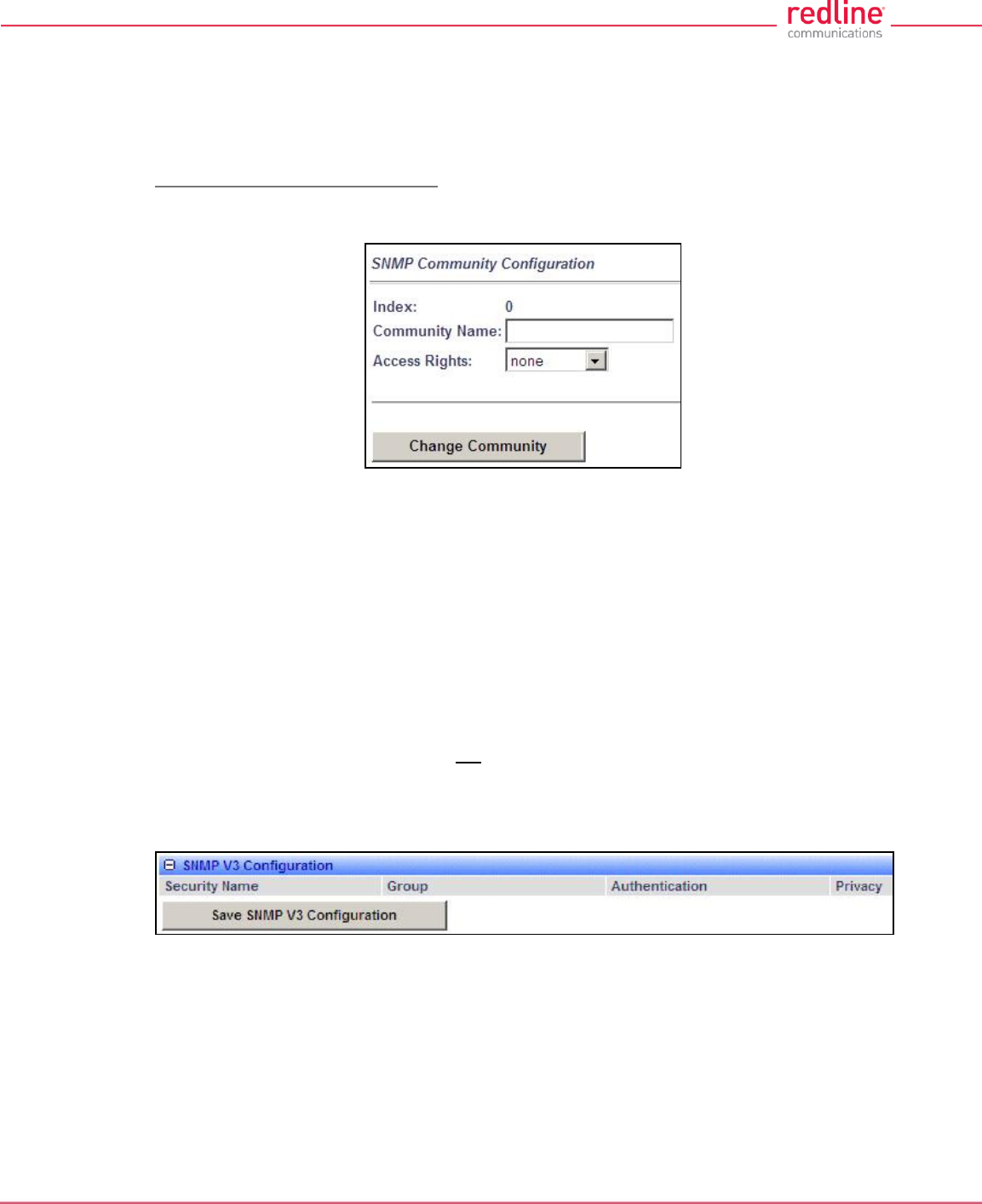
RDL-3000 User Manual
70-00158-01-DRAFT Proprietary Redline Communications © 2010 Page 63 of 142 November 25, 2010
Apply & Save All: Click to activate and permanently save the SNMP Community
settings on this screen. These settings will be restored on power-up, reboot, or at the
end of a test cycle.
Note: Clicking on another main menu item before clicking Apply or Apply & Save All will
discard any changes made to settings displayed on the current screen.
Edit SNMP Community Settings
Click Change or Add in the SNMP Communities section of the screen to modify existing
community strings or add new community strings.
Fig. 40: Web - SNMP Community Configuration Screen
Index: Display the unique reference number for this entry. This value is required when
using the CLI interface to modify SNMP Community settings.
Community Name: Enter or modify the SNMP community name for this entry.
Access Rights: Select the access permissions for this entry.
None: Deny read and write permission for this entry.
Read: Grant read access permission only for this entry. Deny write permission.
Write: Grant write access permission only for this entry. Deny read permission.
Read&Write: Grant read and write access permission for this entry.
Change Community: Click to accept the displayed settings and return to the SNMP
Configuration screen. Clicking does not activate changes.
SNMP v3 Security Settings
SNMP v3 supports authentication and privacy settings to provide secure management
access. Security methods are associated with RDL-3000 user accounts.
Fig. 41: Web - SNMP V3 Configuration
Security Name: User name of the SNMP v3 account.
Group: Group association for the SNMP v3 account.
Authentication: Authorization method for the SNMP v3 account.
MD5: MD5 (Message-Digest algorithm 5) is a cryptographic hash function with a
128-bit hash value (RFC 1321).
SHA: SHA (secure Hash Algorithm) is a set of cryptographic hash functions.
Privacy: Privacy method for this account.
None: Deny read and write permission for this entry.
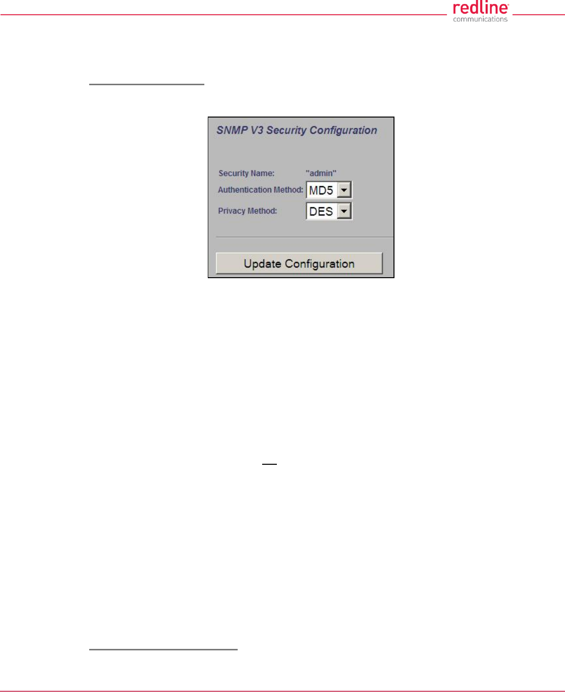
RDL-3000 User Manual
70-00158-01-DRAFT Proprietary Redline Communications © 2010 Page 64 of 142 November 25, 2010
DES: DES (Data Encryption Standard) is an encryption standard.
AES: AES (Advanced Encryption Standard) is an encryption standard.
Save SNMP v3 Configuration: Click to activate the displayed settings.
Edit SNMP v3 Security
Click Change or Add in the SNMP community section of the screen to modify the
associated SNMP v3 security settings. The following popup dialog is displayed:
Fig. 42: Web - SNMP v3 Configuration Dialog
Security Name: name of the selected account to use for SNMP v3 requests.
Authentication Method: Select the access permissions for this entry.
MD5: MD5 (Message-Digest algorithm 5) is a cryptographic hash function with a
128-bit hash value (RFC 1321).
SHA: SHA (secure Hash Algorith) is a set of cryptographic hash functions.
Privacy Method: Select the access permissions for this entry.
None: Deny read and write permission for this entry.
DES: DES (Data Encryption Standard) is an encryption standard.
AES: AES (Advanced Encryption Standard) is an encryption standard.
Update Configuration: Click to accept the displayed settings and return to the SNMP
Configuration screen. Clicking does not activate changes.
SNMP Trap Destination Settings
This section of the SNMP Configuration screen displays the SNMP trap destination
settings. SNMP trap messages inform network management devices of changes to the
RDL-3000 status.
IP Address (IPv4): IP address of this trap listener. A copy of each SNMP trap message
is transmitted to this address.
Port: Destination port address of this trap listener.
Community String: (SNMP v2) Community string associated with this trap listener.
User Name: (SNMP v3) User account associated with this trap listener.
Change: Click Change to modify the existing SNMP community string.
Add: Click to create a new SNMP community string (up to eight community strings).
Edit SNMP Trap Destinations
Click Change or Add in the SNMP Trap Destinations section of the screen to modify the
list of trap listeners. The following popup dialog is displayed:
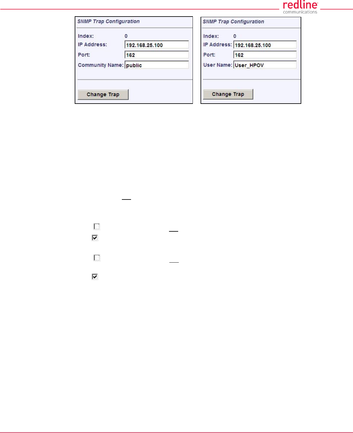
RDL-3000 User Manual
70-00158-01-DRAFT Proprietary Redline Communications © 2010 Page 65 of 142 November 25, 2010
Fig. 43: Web - SNMP Trap Configuration Screen (V2/V3)
Index: Display the unique reference number for this entry. This value is required when
using the CLI interface to modify SNMP trap settings.
IP Address: Enter the IP address (IPv4) associated with this SNMP trap alarm.
Port: Enter the destination port address associated with this SNMP trap alarm.
Community Name: (v2) Enter the community name associated with this trap
destination.
User Name: (v3) Enter the user account associated with this trap destination.
Change Trap: Click to accept these settings and return to the SNMP Configuration
screen. Clicking does not activate changes.
SNMP Trap Settings
SNMP Traps Enabled: Control the SNMP trap message function.
Disabled ( ): The RDL-3000 does not send SNMP trap messages.
Enabled ( ): The RDL-3000 sends SNMP trap messages.
Link Up/Down Trap Enabled: Control SNMP trap messages for the link status.
Disabled ( ): The RDL-3000 does not send SNMP trap messages based on changes
to the wireless link status.
Enabled ( ): A trap message is sent for each change to the wireless link status.
Apply: Click to activate the displayed SNMP Trap Destinations and SNMP Trap
Configuration settings.
Apply & Save All: Click to activate and permanently save the SNMP Trap Destinations
and SNMP Trap Configuration settings displayed on this screen. These settings will be
restored on power-up, reboot, or at the end of a test cycle.
Note: Clicking on another main menu item before clicking Apply or Apply & Save All will
discard any changes made to settings displayed on the current screen.
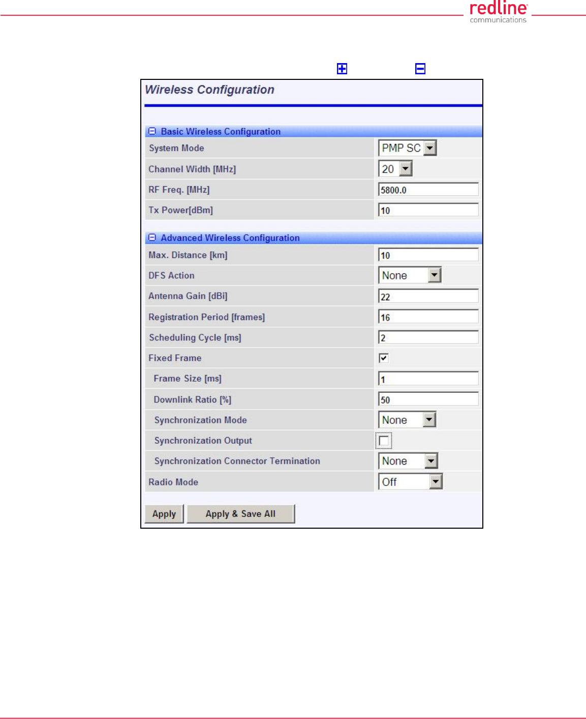
RDL-3000 User Manual
70-00158-01-DRAFT Proprietary Redline Communications © 2010 Page 66 of 142 November 25, 2010
4.5.4 Wireless Configuration
Use these settings to configure the RDL-3000 wireless interface. This screen is different
on the sector controller and subscriber unit. Click to expand or to hide fields.
Fig. 44: Web - Wireless Configuration Screen -- Sector Controller
Basic Wireless Configuration
System Mode: The system designated as sector controller establishes and manages
the bi-directional data link with a remote end RDL-3000. Only one system in a wireless
link must be set for Sector Controller mode (PMP SC).
PMP SC: RDL-3000 automatically sends poll messages to locate and register
remote RDL-3000 subscribers, and negotiates operating settings for the link.
PMP SS: RDL-3000 monitors the selected channel(s) until polled by the PMP Sector
Controller.
Channel Width [MHz]: Select the channel bandwidth. The options key controls channel
availability.
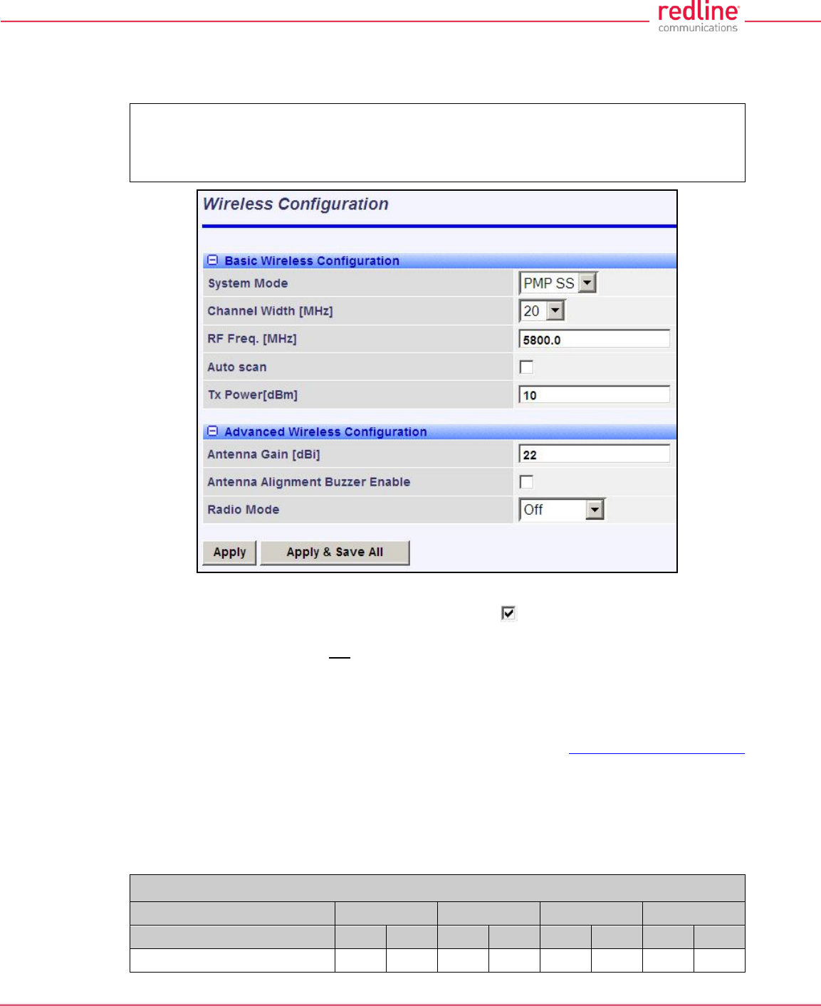
RDL-3000 User Manual
70-00158-01-DRAFT Proprietary Redline Communications © 2010 Page 67 of 142 November 25, 2010
RF Freq. [MHz]: Enter the center frequency for the RF channel.
The options key controls channel availability. Use the Auto scan feature to enable
subscribers to scan multiple channels.
Important: To minimize interference between RDL-3000 links operating in close
proximity, RF frequency settings should be separated by a guard interval equal or
greater than the channel size. For example, when using a 20 MHz channel, the RF
frequencies should be separated by >20 MHz.
Fig. 45: Web - Wireless Configuration Screen -- Subscriber
Auto scan: (Subscriber Only) Check this box to enable the subscriber to
automatically scan available channels to locate and register with an RDL-3000 PMP
Master. When Auto scan is not enabled, the wireless link can be established only at the
frequency specified in the RF Freq. [MHz] field.
By default, the subscriber will scan the entire frequency band enabled by the options key
(see section 8.3: Regional Codes on page 138). To reduce the scanning/connection
time, the operator may specify a subset of frequency ranges to scan. Click on the main
menu item Configuration -> Frequencies to display the Frequency Management
screen.
Tx Power [dBm]: Enter the transmit power level (dBm). This setting is for the
transceiver output only. The actual EIRP depends on the gain of the connected antenna.
See the following tables to determine the maximum transmit power level available at
each modulation setting. When DFS is enabled, the subscriber Tx power may be
adjusted automatically to avoid falsely triggering the DFS feature.
Table 7: Web - Maximum TX Power Settings (dBm) for All Modes
Modulation
BPSK
QPSK
16 QAM
64 QAM
Code Rate
1/2
3/4
1/2
3/4
1/2
3/4
2/3
3/4
Max. Tx Power
25
25
25
25
23
23
22
22

RDL-3000 User Manual
70-00158-01-DRAFT Proprietary Redline Communications © 2010 Page 68 of 142 November 25, 2010
Important: EIRP Levels: Where required by local regulations, the maximum
operational power per channel for a specific antenna must not exceed the maximum
allowable EIRP levels. See the FCC and CE notices in this manual. The RF output
power settings must be professionally programmed by the manufacturer or a trained
professional installer.
Advanced Wireless Configuration
Max. Distance [km]: (SC only) Enter the distance to the subscriber located farthest
away from the sector controller (outer boundary of sector).
DFS Action: (SC only) Select the mode of operation for DFS.
The PMP SC monitors for interference from radar devices and other equipment using
the same channel frequency. When interference is detected, the PMP SC automatically
takes the selected action:
None: The DFS function is disabled. Where DFS is required by regional regulations,
this feature is permanently enabled at the factory and can not be disabled by the
installer or end-user.
Tx Off: When radar signals are detected the transmitter is switched off for 30
minutes. This action is recorded in the message log and an SNMP trap message is
sent (if SNMP enabled). Following an interval of thirty minutes, the same channel is
monitored for one minute and if there are no DFS triggering events, the system
resumes normal operation. If DFS trigger conditions are still detected, operation is
suspended for an additional thirty minute period.
Chg Freq: When radar signals are detected the transmitter is switched to a different
frequency. This action is logged and a trap message is sent (if enabled). A new
channel is selected based on allowable frequencies for the regulatory region set by
the active options key. Each selected channel is monitored for one minute, and if
DFS triggering events are detected, the next available channel is selected. The
system is not allowed to return to a channel on which DFS trigger events were
detected for a period of thirty minutes. If DFS trigger events are detected on all
channels, operation is suspended until the time expires for at least one channel.
Antenna Gain: Enter the antenna gain specified by the manufacturer. This field is
required for DFS-enabled systems.
It is important to enter the correct value. If this value is set higher than the true gain, the
sensitivity is too low and the RDL-3000 will not be operating in compliance with the
UK/ETSI standard. If this value is set lower than the true gain, the RDL-3000 is more
sensitive to interference and may experience false triggers.
Antenna Alignment Buzzer Enable: (SS only) Audible antenna alignment tool.
Disabled ( ): The antenna alignment tool is disabled (no tone).
Enabled ( ): The antenna alignment audible tone generator is active. The rate of the
tone increases when a stronger signal is detected.
Registration Period [frames]: (SC only) The polling period for detecting new
subscribers. This period is based on the number of wireless frames transmitted.
Permitted values are 1 to 100 frames (recommended frame period: 4).
Scheduling Cycle: Enter the duration of the traffic scheduling period (e.g., 5 ms). This
setting affects the volume (and latency) of traffic transmitted over the wireless interface
during each cycle.
Longer scheduling cycles can provide more efficient packet processing.
Shorter scheduling cycles can provide lower latency:
RDL-3000 User Manual
70-00158-01-DRAFT Proprietary Redline Communications © 2010 Page 69 of 142 November 25, 2010
DL latency: Avg. 0.5/ Max. 2 * Scheduling Cycle
UL latency: Avg. 0.5/ Max. 3 * Scheduling Cycle
Note: The effects of changes to the scheduling cycle will vary based aggregate traffic
composition (packet rate, packet size, etc).
Fixed Frame: Select the wireless frame mode.
Disabled ( ): RDL-3000 adjusts the wireless frame size dynamically based on uplink
and downlink traffic patterns.
Enabled ( ): Wireless frame size is fixed at the value specified in the Frame Size
field. Fixed frame mode must be used when using synchronization (collocated base
stations). The Fixed Frame size and Downlink Ratio must be identical for all
synchronized base stations operating in a geographical area. When fixed frame mode
is enabled, the PIR is limited as follows:
Max PIR = CIR * Scheduling Cycle / Frame Size
Frame Size [ms]: When Fixed Frame mode is selected, the frame size must be
specified (1 to 20 milliseconds).
Downlink Ratio [%]: (SC only) When Fixed Frame mode is selected, the proportion
of each frame reserved for downlink data must be specified (20-80 %).
Synchronization Mode: (SC only) When Fixed Frame mode is selected, the
synchronization mode must be specified.
None: Synchronization is disabled.
Internal: Transmissions are synchronized to the RDL-3000 internal clock. If a GPS
module is installed and synchronized to one or more satellites, transmissions are
synchronized to the module 1 PPS output.
External: Synchronize this unit to a 1 PPS signal received on the PPS port.
Synchronization Output: (SC only) When Fixed Frame mode is selected, the
synchronization output port (PPS) mode must be specified.
Disabled ( ):The PPS port is disabled.
Enabled ( ): The synchronization port output is active. The synchronization output
port (PPS) termination must be specified.
Synchronization Output Termination: (SC only) When the synchronization port
(PPS) output is enabled, the impedance must be specified. When collocated RDL-
3000 units have the PPS ports cabled together for synchronization, only the last RDL-
3000 in the daisy-chain should have the termination set to 50 or 75 ohms (based on
cable type). Refer to the RDL-3000 Installation Guidelines for more information.
None: Port termination is high impedance.
50 Ohms: Port termination impedance is 50 Ohms.
75 Ohms: Port termination impedance is 75 Ohms.
Radio Enable: Select the operational mode for the antenna system.
Off: RF Port 1 and RF port 2 radio transmitters are disabled (no RF output).
RF Port 1: The RF transmitter on RF Port 1 is enabled (RF port 2 is disabled).
RF Port 2: The RF transmitter on RF Port 2 is enabled (RF port 1 is disabled).
RF Port 1 & 2: The RF transmitter is operating in MIMO mode. Transmitting on port 1
and listening on ports 1 and 2.
RF Port 2 & 1: The RF transmitter is operating in MIMO mode (both ports enabled).
Transmitting on port 2 and listening on ports 1 and 2.
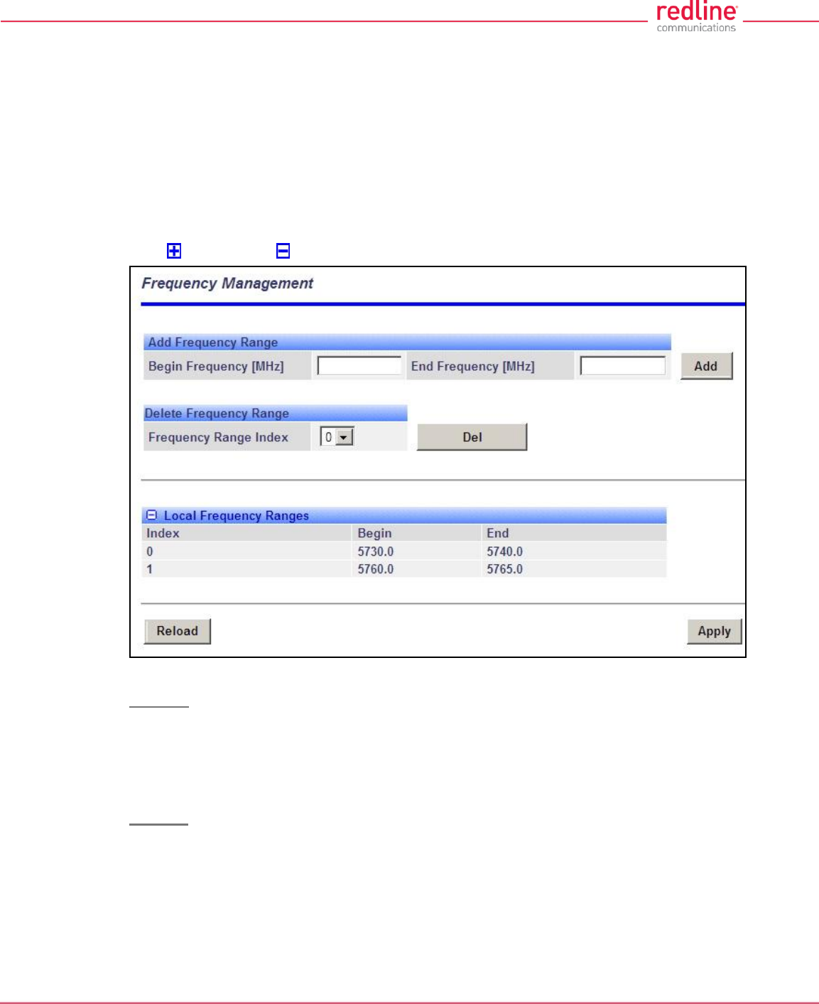
RDL-3000 User Manual
70-00158-01-DRAFT Proprietary Redline Communications © 2010 Page 70 of 142 November 25, 2010
Apply: Click to accept and activate the wireless settings displayed on this screen.
Apply & Save All: Click to permanently save the wireless settings displayed on this
screen. These settings will be restored on power-up, reboot, or at the end of a test cycle.
Note: Clicking on another main menu item before clicking Apply or Apply & Save All will
discard any changes made to settings displayed on the current screen.
Frequency Management Screen
Click Configuration->Wireless->Frequencies to display the Frequency Management
screen. Up to 32 frequency ranges may be entered. Settings entered on the sector
controller are automatically downloaded and used by subscribers with the Auto Scan
feature enabled. This screen is identical for the sector controller and subscriber units.
Click to expand or to hide fields.
Fig. 46: Web - Frequency Management Screen
PMP SC
The sector controller can be programmed with a master list of frequency ranges. When a
subscriber registers with the sector controller, this list is automatically downloaded to the
subscriber and displayed as the Remote Frequency Ranges. Subscribers with Auto
Scan enabled use these downloaded range settings exclusively. These settings remain
in effect until the subscriber is rebooted, at which time the settings are erased.
PMP SS
When no frequency ranges are entered, the subscriber scans all available frequency
ranges for that region to locate a sector controller. If all frequency ranges are scanned
three times without detecting and registering with a sector controller, the subscriber is
gin scanning the entire frequency band enabled by the options key.
Frequency ranges downloaded from the sector controller, or programmed manually, are
scanned as the first priority. Downloaded ranges are deleted when the subscriber is
rebooted.
RDL-3000 User Manual
70-00158-01-DRAFT Proprietary Redline Communications © 2010 Page 71 of 142 November 25, 2010
Add Frequency Range
Begin: Enter the lower limit of the frequency scan interval (MHz). The scan interval
must be a subset of the region frequency range. The unit automatically compensates
for channel size when selecting the center frequency.
End: Enter the upper limit of the frequency scan interval (MHz). The scan interval
must be a subset of the region frequency range. The unit automatically compensates
for channel size when selecting the center frequency.
Add: Click to save the new range settings in the Local Frequency Range list. This
action does not check the validity of the specified range (see Test and Save buttons
at the bottom of the screen).
Delete Frequency Range
Index: Choose the index value of the scan interval to be deleted from local frequency
range table.
Delete: Click to permanently remove the selected (index) scan interval.
Local Frequency Ranges
These settings are saved in non-volatile memory and loaded when the unit is
rebooted.
Index: Index value of this entry in the local frequency range table.
Begin: Lower limit of the frequency scan interval (MHz).
End: Upper limit of the frequency scan interval (MHz).
Remote Frequency Ranges
If values have been downloaded, these settings is used when recovering from a loss
of registration. This list is not saved permanently, and is discarded when the unit is
rebooted.
Controls
Reload: Reload and display the saved (Local) scan intervals. Unsaved changes are
discarded.
Apply: Check the validity of the current range settings in the Local Frequency Range
list. All valid settings are activated.
Note: Click Save All in the main menu to save changes permanently.
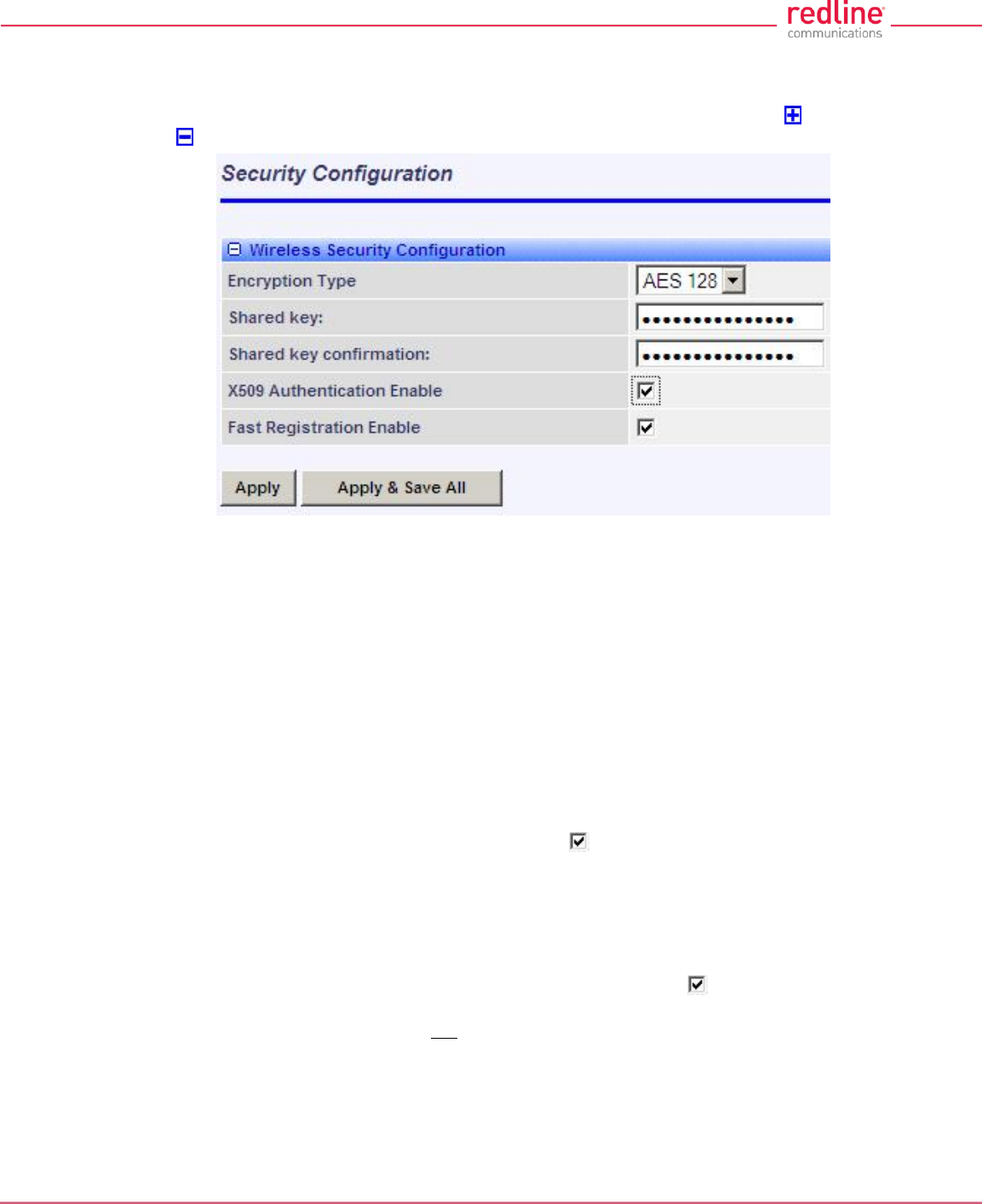
RDL-3000 User Manual
70-00158-01-DRAFT Proprietary Redline Communications © 2010 Page 72 of 142 November 25, 2010
4.5.5 Wireless Security
Click Configuration->Wireless->Security to display the Security Configuration screen.
This screen is identical for the sector controller and subscriber units. Click to expand
or to hide fields.
Fig. 47: Web - Wireless Security Screen - Sector Controller
Encryption Type: Select the encryption type to use for data transmitted over the
wireless interface. If an encryption type is selected, the identical setting must be made
on both communicating units before Ethernet packets can be transferred over-the-air.
None: Encryption is disabled.*
AES 128: Advanced Encryption Standard using 128-bit encryption.
AES 192: Advanced Encryption Standard using 192-bit encryption.
AES 256: Advanced Encryption Standard using 256-bit encryption.
Shared key: Enter the encryption key to be shared between the sector controller and all
subscribers in this sector. This is required only when encryption is enabled.
Shared key confirmation: Re-enter key to minimize errors. This field must be identical
to the Shared Key field.
X.509 Authentication Enable: Check this box to require authentication using an
installed X.509 certificate. The user-defined unit certificate, authority certificate, and RSA
private key must be downloaded using the CLI 'load' command. Uncheck this box to
allow network connections without requiring authentication.
Note: This dialog item is visible only if enabled by the Options Key and X.509 certificates
are loaded on the RDL-3000.
Fast Registration Enable: (Subscriber only) Check this box to enable the sector
controller to use pre-shared keys for quick authentication of a subscriber (bypass Diffie-
Hellman method). This feature is not available in FIPS mode.
SC MAC: (Subscriber only) MAC address of the sector controller. The subscriber will
establish a wireless link only with the base station having the MAC address recorded in
this field. If this field is blank, the subscriber will establish a wireless link with any base
station.
Apply: Click to activate the security settings displayed on this screen.
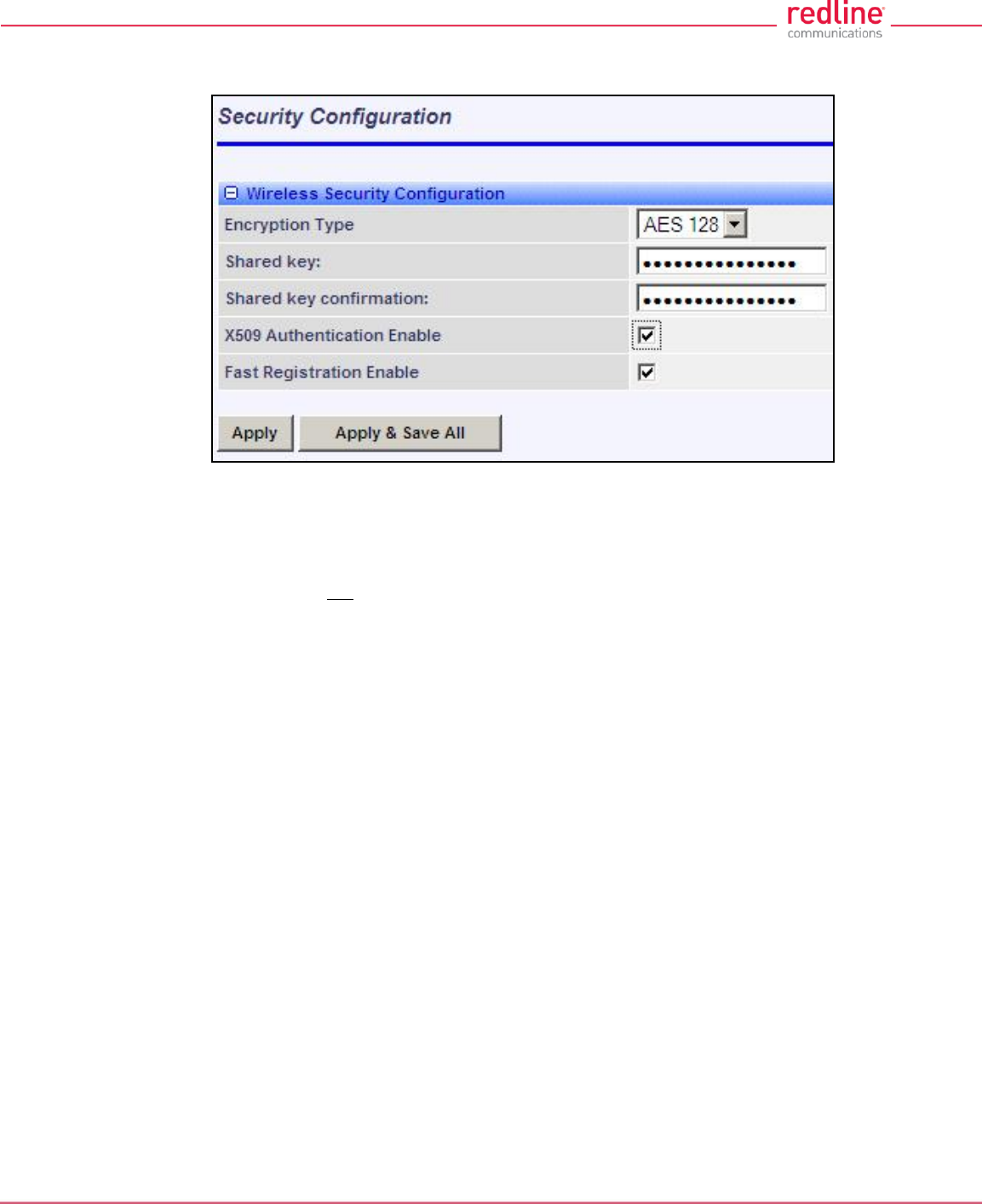
RDL-3000 User Manual
70-00158-01-DRAFT Proprietary Redline Communications © 2010 Page 73 of 142 November 25, 2010
Apply & Save All: Click to activate and permanently save the security settings on this
screen. These settings will be restored on power-up, reboot, or at the end of a test cycle.
Fig. 48: Web - Wireless Security Screen - Subscriber
Notes:
1. Clicking on another main menu item before clicking Apply or Apply & Save All will
discard any changes made to settings displayed on the current screen.
2. HTTPS (SSL) is not available until an X.509 certificate and DSA private key have
been loaded (ssl_cert_<mac>.pem and ssl_key_<mac>.pem).
3. AES encryption is not available until the X.509 certificate and key files have been
loaded (usr_wacert_<mac>.der, usr_wcert_<mac>.der, and usr_wkey_<mac>.der).
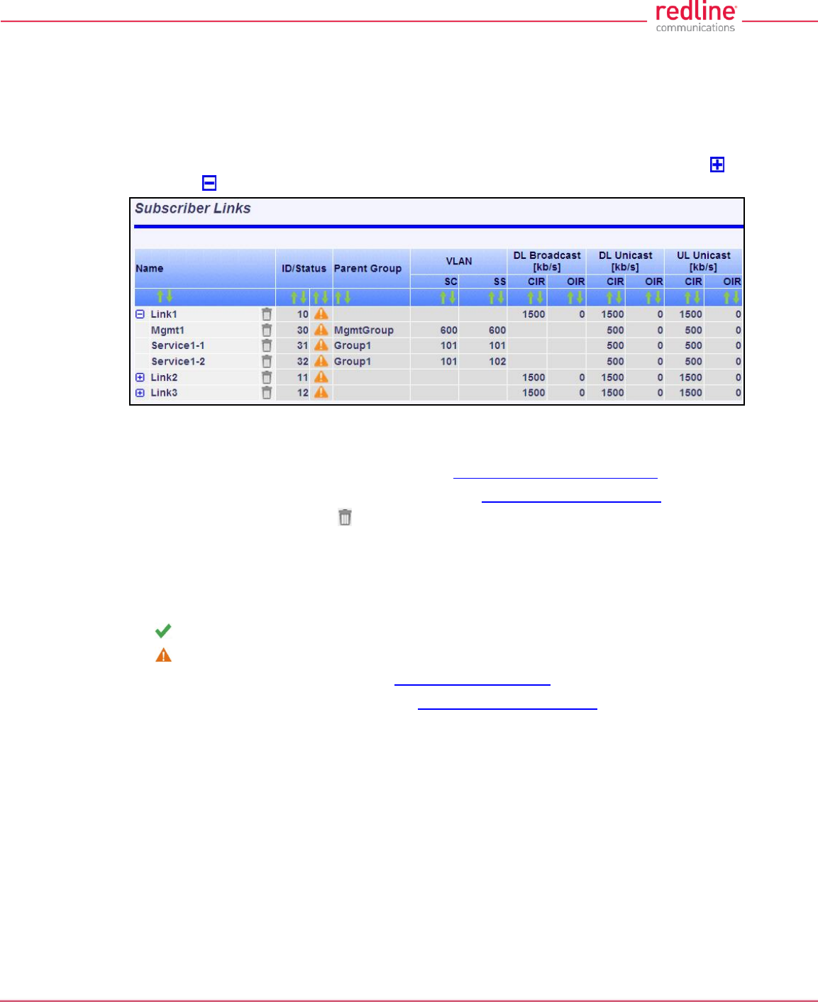
RDL-3000 User Manual
70-00158-01-DRAFT Proprietary Redline Communications © 2010 Page 74 of 142 November 25, 2010
4.6 Provisioning Screens
This section describes monitoring and configuring Links, Service Groups, and Services.
4.6.1 Subscriber Links
The Subscriber Links screen provides a summary view of configuration settings for all
Subscriber Links and provisioned Services. Click Provisioning->Subscriber Links in
the main menu to display operating statistics for all subscriber wireless links. Click to
expand or to hide Service names.
Fig. 49: Web - Links Screen (Master List)
Name: Operator-assigned name for wireless Subscriber Links and Services.
Click the Link name (e.g., Link1) to display the Subscriber Link Configuration screen.
Click the Service Name (Service1-1) to display the Subscriber Service Status screen.
Click on the trashcan symbol ( ) to delete this Link.
ID/Status: Subscriber Link or Service identifier and status indicator.
ID: Numeric ID generated automatically when creating the Subscriber Link. This
value is required when using the CLI interface to modify provisioning settings.
Status: Graphic indication of the status of this Link or Service.
The Subscriber Link or Service is available (online).
The Subscriber Link or Service is unavailable (offline or disabled).
Click the Link status to display the Subscriber Link Status screen
Click the Service status to display the Subscriber Service Status screen.
Parent Group: The Service is a member of this Service Group.
VLAN: VLAN tagging settings.
SC: VLAN classification for this Service Group. This Service Group processes only
ingress packets (sector controller Ethernet port) having this VID. This VID is removed
before the packet is forwarded over the wireless interface.
Each egress packet belonging to this Service Group has this VID added (Q-in-Q) before
the packet is forwarded over the sector controller Ethernet port.
SS: VLAN classification for this Service.
This Service processes only ingress packets (subscriber Ethernet port) having this VID.
This VID is removed before the packet is forwarded over the wireless interface. Each
egress packet belonging to this Service has this VID added (Q-in-Q) before the packet is
forwarded over the subscriber Ethernet port.
DL Broadcast (Kbps): Broadcast traffic downlink rates.

RDL-3000 User Manual
70-00158-01-DRAFT Proprietary Redline Communications © 2010 Page 75 of 142 November 25, 2010
CIR: Requested minimum committed downlink bandwidth.
OIR: Calculated available downlink bandwidth (based on scheduling cycle).
DL Unicast (Kbps): Unicast traffic downlink rates.
CIR: Requested minimum committed downlink bandwidth.
OIR: Available downlink bandwidth (based on scheduling cycle).
UL Unicast (Kbps): Unicast traffic uplink rates.
CIR: Requested minimum committed uplink bandwidth.
OIR: Calculated available uplink bandwidth (based on scheduling cycle).
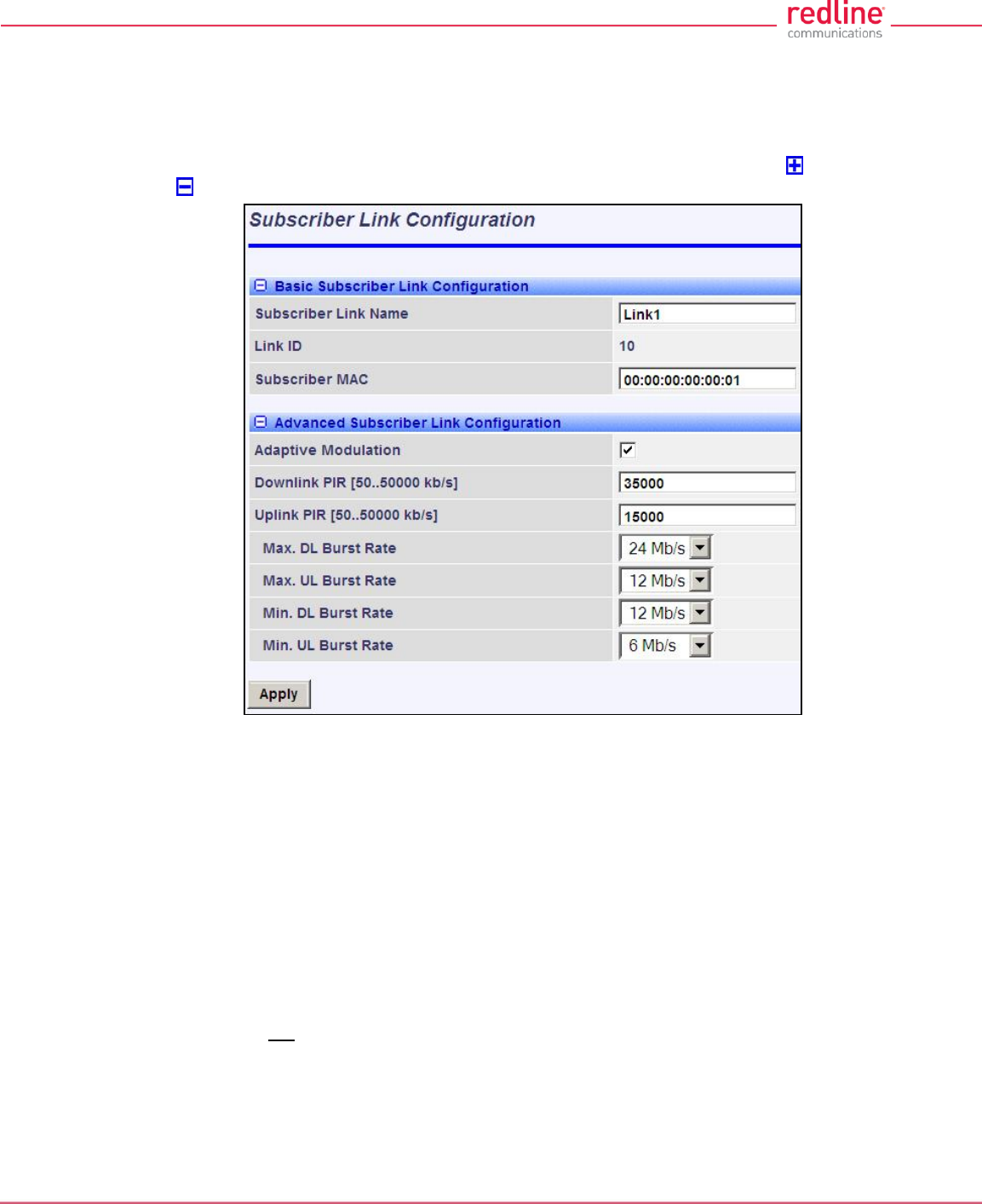
RDL-3000 User Manual
70-00158-01-DRAFT Proprietary Redline Communications © 2010 Page 76 of 142 November 25, 2010
4.6.2 Subscriber Link Configuration
Use this screen to display and modify settings for a Subscriber Link.
Click Provisioning-> New Subscriber Link in the main menu to add a new Subscriber
Link. To edit an existing Subscriber Link, click Provisioning-> Subscriber Links in the
main menu and click on the name of the Subscriber Link (e.g., Link1). Click to expand
or to hide fields.
Fig. 50: Web - Subscriber Link Configuration Screen
Basic Subscriber Link Configuration
Subscriber Link Name: Enter a name to identify this wireless link. This identifier is
displayed on configuration and statistics screens. The name may contain up to fifteen
alpha-numeric characters including a-z, A-Z, 0-9, dash (-), and underscore (_).
Link ID: (Read only) A unique numeric ID generated automatically when the Subscriber
Link is created. This value is required when using the CLI interface to modify SNMP
settings.
Subscriber MAC: Enter the MAC address of the subscriber for this wireless link. The
sector controller will establish a wireless link only with the subscriber having this MAC
address.
For example, when a subscriber unit is replaced (e.g., hardware upgrade), the sector
controller will not establish a wireless link until this field is updated with the MAC address
of the replacement unit.
Advanced Subscriber Link Configuration
Adaptive Modulation: The adaptive modulation feature automatically adjusts
modulation and coding settings to maintain wireless link operation during periods of

RDL-3000 User Manual
70-00158-01-DRAFT Proprietary Redline Communications © 2010 Page 77 of 142 November 25, 2010
transient interference, power variations (fade), and reflections. Adaptive modulation can
be enabled or disabled individually for each Subscriber Link.
When Adaptive modulation is disabled, the modulation and coding are adjusted
automatically to achieve the highest throughput where packet error rates (PER) are
lower than factory-set values. When packet error rates exceed this threshold, the
modulation/code combination is adjusted to maintain the connection at a lower
throughput rate (graceful degradation). The operator must select the maximum and
minimum burst rates for the uplink and downlink.
When Adaptive modulation is disabled, the operator must select only the maximum
uncoded burst rate (UBR) for the uplink and downlink.
Max. DL Burst Rate: Maximum downlink UBR for unicast traffic to this subscriber.
Max. UL Burst Rate: Maximum uplink UBR for unicast traffic from this subscriber.
When Adaptive modulation is enabled, the operator must also select the maximum
uncoded burst rate (UBR) for the uplink and downlink.
Min. DL Burst Rate: (Displayed only when adaptive modulation is enabled) Minimum
downlink UBR for unicast traffic. When the downlink rate falls below this threshold, the
affected rate statistics are displayed in red (Subscriber Links Summary screen) and the
downlink PIR for all Services/Service Groups are reduced proportionally until the
condition clears.
Min UL Burst Rate: (Displayed only when adaptive modulation is enabled) Minimum
uplink UBR for unicast traffic. When the uplink rate falls below this threshold, the
affected rate statistics are displayed in red (Subscriber Links Summary screen) and the
downlink PIR for all Services/Service Groups are reduced proportionally until the
condition clears.
Note: Adjustments to modulation and coding cause temporary changes to the PIR of all
connections on that wireless link. This ensures degradation of the RF signal on any
wireless link does not affect the throughput of other links in the sector.
When adaptive modulation adjusts the uplink or downlink modulation/coding settings of a
wireless link to below the desired minimum burst rate setting, the burst rates are
displayed in red and the
Example: In a link operating at 16 QAM 3/4, transient interference may result in a
temporary change from to 16 QAM 1/2 to maintain the required PER. The RDL-3000
periodically tests transmission at a higher rate and resumes operation at the normal rate
after the interference has cleared.
Downlink PIR: Enter the peak downlink information rate (aggregate downlink traffic for
all Services and Service Groups).
Uplink PIR: Enter the peak uplink information rate (aggregate uplink traffic for all
Services and Service Groups).
Note: Uplink and downlink traffic transmitted over the wireless interface is monitored to
enforce PIR settings (50 - 50000 Kbps). Traffic statistics are reset at the beginning of
each common one-second clock tick. If the maximum throughput is reached on any Link
before the end of the current interval, that Link is excluded from sending additional traffic
until after the next clock tick.
For example, if a Link transmits its full data allocation in the first 650 ms of the current
metering interval, the Link will not receive any additional bandwidth allocation until the
beginning of the next interval (enforced pause of 350 ms).

RDL-3000 User Manual
70-00158-01-DRAFT Proprietary Redline Communications © 2010 Page 78 of 142 November 25, 2010
When adaptive modulation is enabled, automatic adjustments to the modulation/coding
will result in relative changes to the PIR of that wireless link. Incorrect PIR settings may
result in excessive latency or dropped packets (buffer full condition).
DL Burst Rate: Downlink burst rate for unicast traffic. The RDL-3000 will establish a
wireless link only at the specified rate. The communicating wireless unit must also be
operating at the same fixed rate.
UL Burst Rate: Uplink burst rate for unicast traffic. The RDL-3000 will establish a
wireless link only at the specified rate. The communicating wireless unit must also be
operating at the same fixed rate.
Controls
Apply: Click to accept and activate displayed settings.
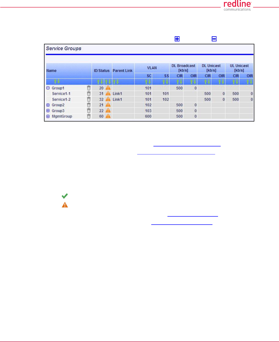
RDL-3000 User Manual
70-00158-01-DRAFT Proprietary Redline Communications © 2010 Page 79 of 142 November 25, 2010
4.6.3 Service Groups
The Service Groups screen provides a summary view of configuration settings for all
Service Groups and provisioned Services. Click Provisioning->Service Groups in the
main menu to display the Service Groups screen. Click to expand or to hide fields.
Fig. 51: Web - Service Groups Screen (Master List)
Name: Identifies Service Groups and member Services.
Click the Service Group name to display the Service Group Configuration screen.
Click the Service name to display the Subscriber Service Configuration screen.
ID/Status: Identifier and status for the Subscriber Link or Service.
ID: Unique identifier for this Service Group or Service. A unique numeric ID
generated automatically when the Service Group or Service was created. This value
is required when using the CLI interface to modify Service Group or Service settings.
Status: The status of this Service Group or Service.
Service Group or Service is available.
Service Group or Service is unavailable (down/offline).
Click the Service Group status to display the Service Group Status screen.
Click the Service status to display the Subscriber Service Status screen.
Parent Link: The Service is assigned to this Subscriber Link.
VLAN: VLAN classification settings.
SC: VLAN classification setting at the sector controller (Service Group).
SS: VLAN classification setting at the subscriber (Service).
DL Broadcast (Kbps): Minimum rate for downlink broadcast traffic.
CIR: Operator requested bandwidth.
OIR: Assigned bandwidth.
UL Unicast (Kbps): Minimum rate for uplink unicast traffic.
CIR: Operator requested bandwidth.
OIR: Assigned bandwidth.
DL Unicast (Kbps): Minimum rate for downlink unicast traffic.
CIR: Operator requested bandwidth.
OIR: Assigned bandwidth.
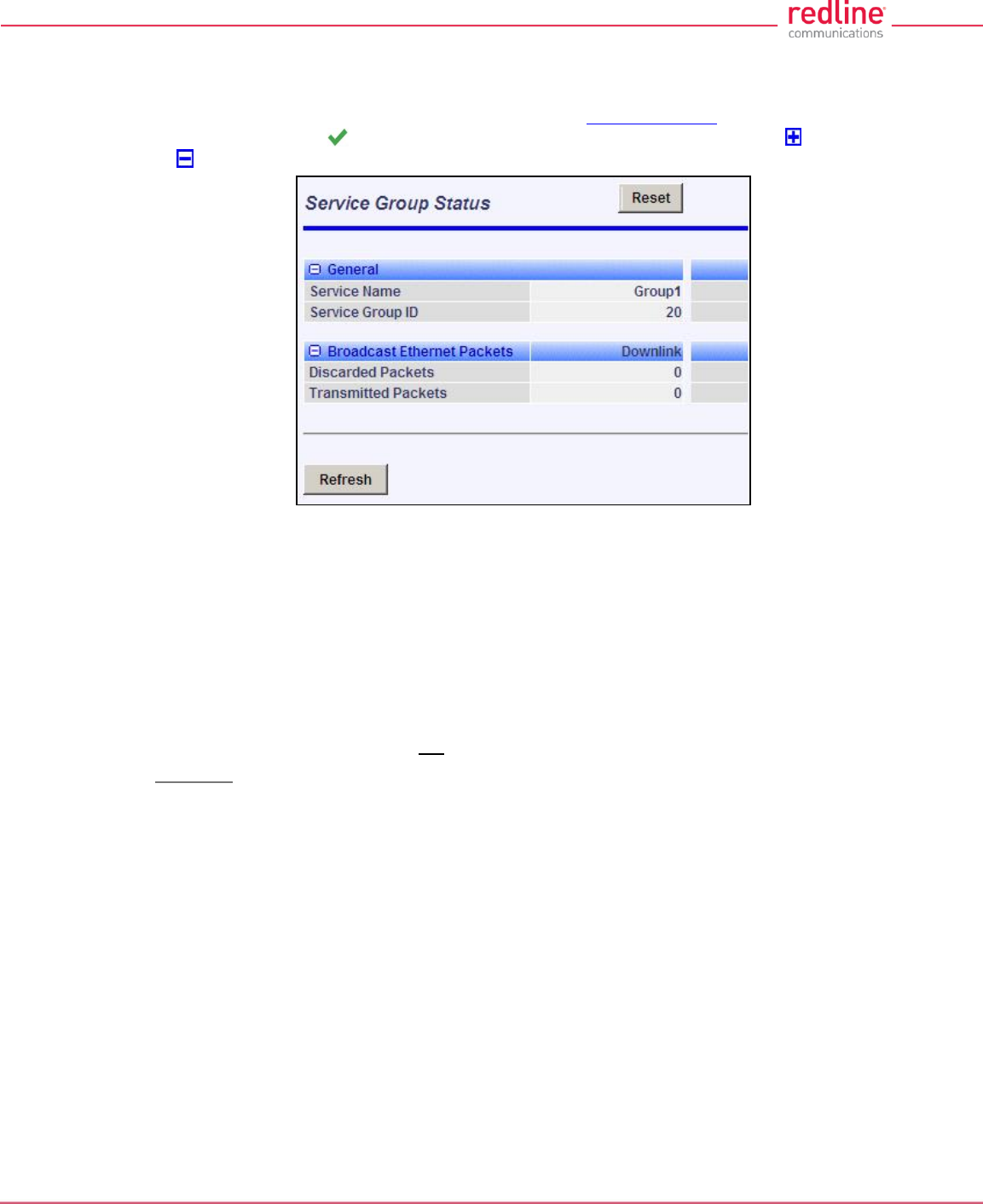
RDL-3000 User Manual
70-00158-01-DRAFT Proprietary Redline Communications © 2010 Page 80 of 142 November 25, 2010
4.6.4 Service Group Status
Use this screen to monitor the status of all Service Groups. Click Provisioning-
>Service Groups in the main menu to display the Service Groups screen. Click on the
status symbol (e.g., ) to display the Service Group Status screen. Click to expand
or to hide fields.
Fig. 52: Web - Service Group Status Screen
General
Service Group Name: Name of the Service Group.
Service Group ID: A unique numeric ID for this Service Group. This value is required
when using the CLI interface to modify Service Group settings.
Broadcast Ethernet packets
Discarded Packets: Total packets discarded by the local system due to errors.
Transmitted Packets: Total broadcast (or multicast) packets successfully transmitted
over the wireless interface (does not include discarded or errored packets).
Controls
Reset: Click to reset displayed statistics counters.
Refresh: Click to update displayed statistics counters.
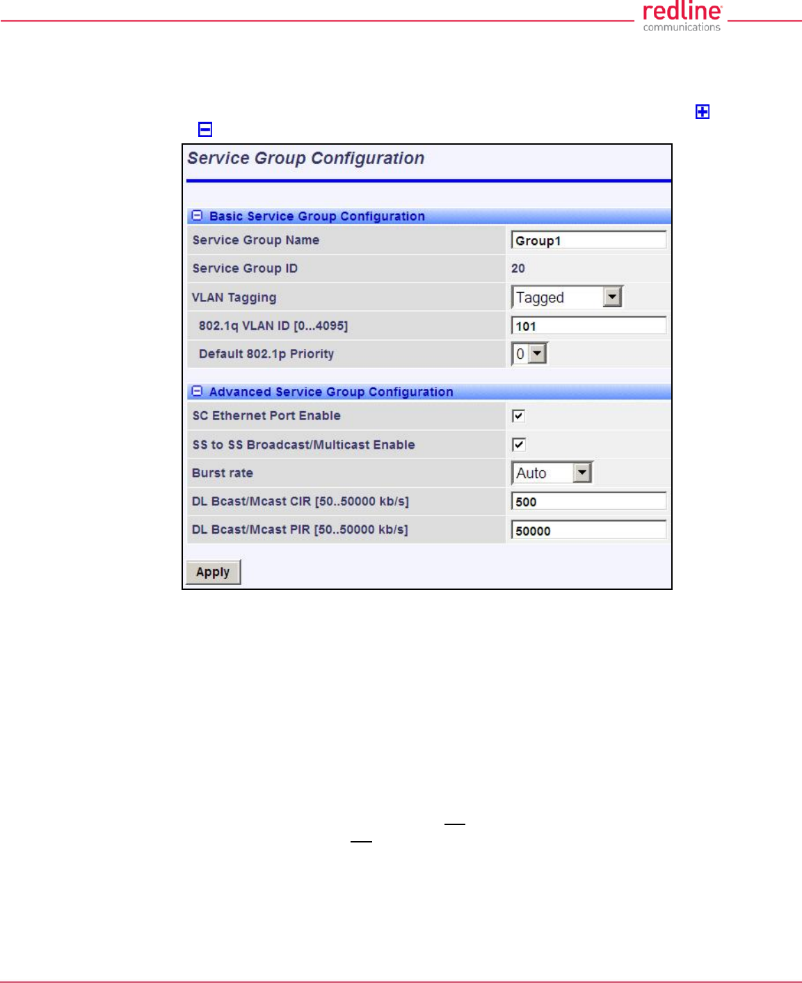
RDL-3000 User Manual
70-00158-01-DRAFT Proprietary Redline Communications © 2010 Page 81 of 142 November 25, 2010
4.6.5 Service Group Configuration
Use this screen to create new Service Groups or view/modify existing Service Groups.
Click Service Groups in the main menu, locate the desired Service Group in the table,
and click on the Service Group name (Name column) to display this screen. Click to
expand or to hide fields.
Fig. 53: Web - Service Group Configuration Screen
Basic Service Group Configuration
Service Group Name: Enter a unique name to identify this Service group. This identifier
is displayed on configuration and statistics screens. The name may contain up to fifteen
(15) alpha-numeric characters including a-z, A-Z, 0-9, dash (-), and underscore (_).
Service Group ID: (Read only) A unique numeric ID generated automatically when a
Service Group is created. This value is required when using the CLI interface to modify
Service Group settings.
VLAN Tagging: Select the classification mode for this Service Group.
Tagged: Select tagged to associate a unique VID with this Group.
Pass-through: Classify all packets that do not have a VLAN ID, or where the
outermost VLAN ID tag does not match the VLAN ID for any tagged Group. Ethernet
ingress port are discarded.
802.1Q VLAN ID [0-4095]: Enter the VID associated with this Group definition.
This field is used only when 'Tagged' is selected in the Group Tagging Mode field.
Default Priority: Enter the default 802.1p priority setting.
RDL-3000 User Manual
70-00158-01-DRAFT Proprietary Redline Communications © 2010 Page 82 of 142 November 25, 2010
The default priority is used to set the 802.1p priority field when a Service Group is set to
Tagged mode (add VLAN tag) and no priority information was received with the packet.
Advanced Service Group Configuration
SC Ethernet Port Enable: Controls the function of the sector controller Ethernet port for
group multicast traffic.
Enabled ( ): Broadcast and multicast traffic received from subscribers is forwarded
over the sector controller Ethernet port.
Disabled ( ): Broadcast and multicast traffic received from subscribers is not
forwarded over the sector controller Ethernet port.
SS To SS Broadcast and multicast Enable:
Enabled ( ): Broadcast and multicast traffic received from subscribers is forwarded
over the wireless interface to all subscribers associated with the group.
Disabled ( ): Broadcast and multicast traffic received from subscribers is not
forward over the wireless interface.
Burst Rate: Enter the uncoded burst rate for downlink broadcast and multicast traffic
belonging to this Group. Use the 'Auto' setting (recommended) to have the rate selected
automatically based on the current operating conditions. To set this to a fixed value, first
identify the group member having the lowest Max DL Burst Rate setting, and then
calculate the rate using the formula:
Burst_Rate = Max DL Burst Rate - 1
Note: Applications requiring a higher broadcast or multicast rate (e.g., video) may use a
higher setting at the risk of less reliable retransmissions.
DL Bcast/Mcast CIR [50..50000 Kbps]: Set the CIR for downlink broadcast and
multicast traffic belonging to this group.
DL Bcast/Mcast PIR [50..50000 Kbps]: Set the PIR for downlink broadcast and
multicast traffic belonging to this group.
Note: Traffic transmitted over the wireless interface is monitored to enforce CIR/PIR
settings. Traffic statistics are reset at the beginning of each common one-second clock
tick. When adaptive modulation is enabled, automatic adjustments to the
modulation/coding will result in relative changes to the CIR/PIR of that wireless link.
Controls
Apply: Click to accept and activate displayed settings.
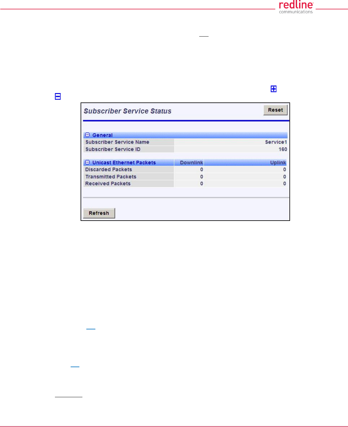
RDL-3000 User Manual
70-00158-01-DRAFT Proprietary Redline Communications © 2010 Page 83 of 142 November 25, 2010
4.6.6 Subscriber Service Status
Services status and configuration screens can not be displayed directly; the operator
must first select a Subscriber Link or Service Group, and then choose the Service from
the list. Refer to the following screens:
4.4.5: Subscriber Services Summary Screen (SS Only) on page 53
4.6.1: Subscriber Links on page 74
4.6.3: Service Groups on page 79
This screen displays status and statistics information for a Service. Click to expand or
to hide fields.
Fig. 54: Web - Service Status Screen
General
Service Name: Operator-assigned name for this Service.
Service ID: A unique numeric ID generated automatically when the Service was created.
This value is required when using the CLI interface to modify Service settings.
Ethernet Packets
Packets: Discarded: Total number of packets discarded by the local system due to errors.
Rx: Received wireless packets discarded.
Tx: Transmitted wireless packets discarded by remote end unit.
Packets Transmitted: Total packets successfully processed over the wireless interface.
Total does not include discarded or errored packets.
Rx: Total received wireless packets.
Tx: Total transmitted wireless packets.
Packets Received: Total packets successfully processed over the wireless interface. Total
does not include discarded or errored packets.
Rx: Total received wireless packets.
Tx: Total transmitted wireless packets.
Controls
Reset: Click to zero all displayed statistics counters.
Refresh: Click to update displayed statistics counters.
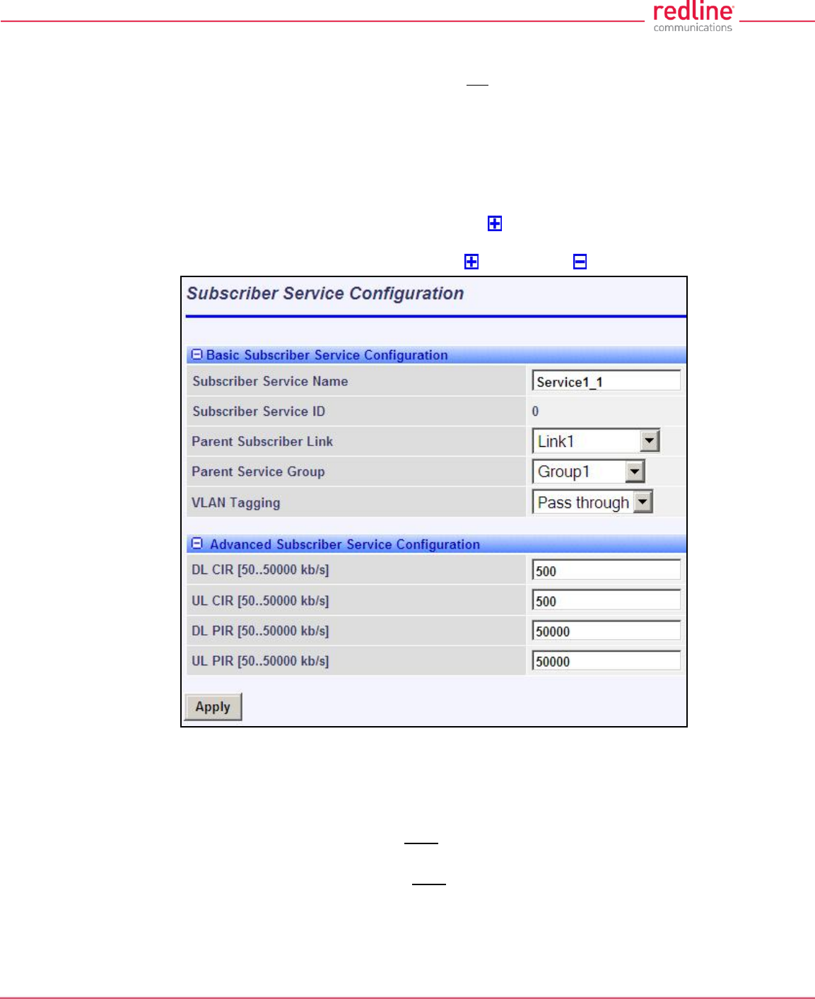
RDL-3000 User Manual
70-00158-01-DRAFT Proprietary Redline Communications © 2010 Page 84 of 142 November 25, 2010
4.6.7 Subscriber Service Configuration
Services status and configuration screens can not be displayed directly; the operator
must first select a Subscriber Link or Service Group, and then choose the Service from
the list. Refer to the following screens:
4.4.5: Subscriber Services Summary Screen (SS Only) on page 53
4.6.1: Subscriber Links on page 74
4.6.3: Service Groups on page 79
To add a new Service, click New Service in the main menu. To edit existing Services,
click Subscriber Links in the main menu, click to expand the Link hosting this
Service, and then click the Service name (Name field). The Service Configuration screen
is displayed and the fields can be updated. Click to expand or to hide fields.
Fig. 55: Web - Service Configuration Screen
Basic Service Configuration
Service Name: Enter a name for this Service (15 characters maximum). The Service
name is displayed on configuration and statistics screens.
Parent Subscriber Link: Each Service must be associated with a Link (subscriber). Use
the drop-down menu to choose the Subscriber Link for this service.
Parent Service Group: Each Service must be associated with a Service Group to
manage broadcast and multicast traffic. Use the drop-down menu to choose the Service
Group for this service.
VLAN Tagging: Select the classification mode for this Service.
Tagged: Select tagged to associate a unique VID with this Group.

RDL-3000 User Manual
70-00158-01-DRAFT Proprietary Redline Communications © 2010 Page 85 of 142 November 25, 2010
Pass-through: Classify all packets that do not have a VLAN tag, or where the
outermost VLAN ID tag does not match the VLAN ID for any tagged Group.
802.1Q VLAN ID [0-4095]: Enter the VID associated with this Group definition.
This field is used only when 'Tagged' is selected in the Group Tagging Mode field.
Default Priority: Enter the default 802.1p priority setting.
The default priority is used to set the 802.1p priority field when a Service is set to
Tagged mode (add VLAN tag) and no priority information was received with the
packet.
Advanced Service Configuration
DL CIR: Enter the committed information rate for downlink unicast traffic.
UL CIR: Enter the committed information rate for uplink unicast traffic.
DL PIR: Enter the peak information rate for downlink unicast traffic.
UL PIR: Enter the peak information rate for uplink unicast traffic
The traffic each Service transmits over the wireless interface is monitored to enforce
PIR settings (50 - 50000 Kbps). Traffic statistics are reset at the beginning of each
common one-second clock tick. If the maximum throughput is reached on any Service
before the end of the current interval, that Service is excluded from sending additional
traffic until after the next clock tick.
For example, if a Service transmits its full data allocation in the first 650 ms of the
current metering interval, that Service will not receive any additional bandwidth allocation
until the beginning of the next interval (enforced pause of 350 ms).
When adaptive modulation is enabled, automatic adjustments to the modulation/coding
will result in relative changes to the PIR of all Services and Service Groups using that
wireless link. Incorrect PIR settings may result in excessive latency or dropped packets
(buffer full condition).
Controls
Apply: Click to accept and activate displayed settings.
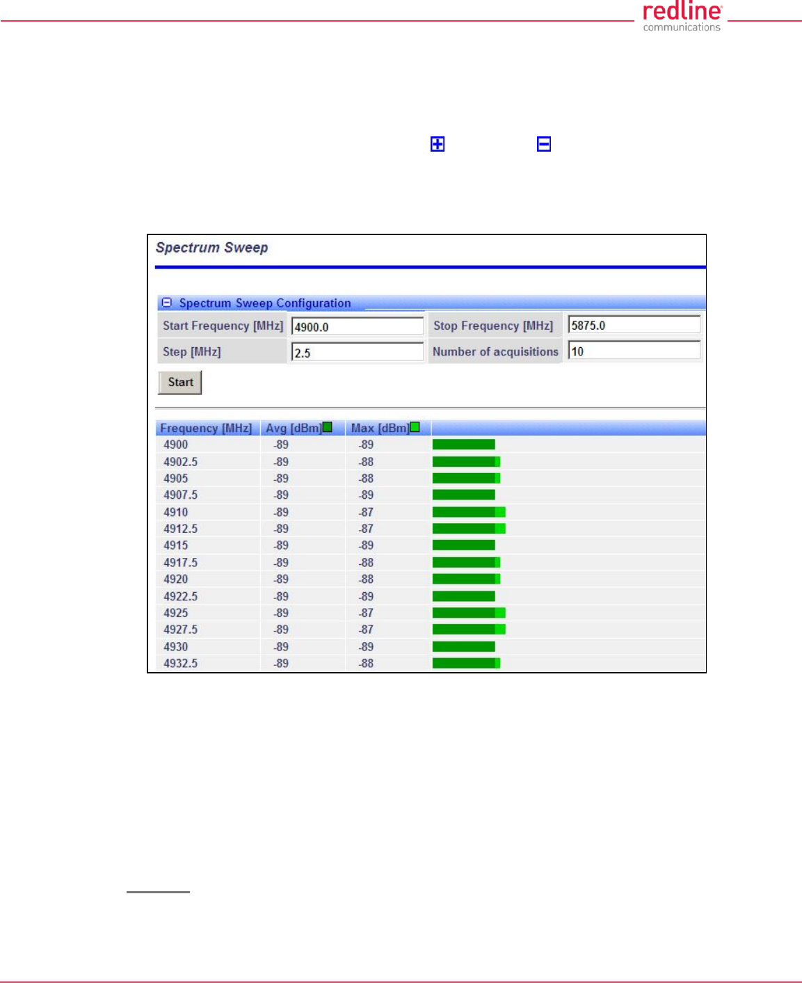
RDL-3000 User Manual
70-00158-01-DRAFT Proprietary Redline Communications © 2010 Page 86 of 142 November 25, 2010
4.7 Utilities Screens
4.7.1 Spectrum Sweep
Use the RDL-3000 Spectrum Sweep feature to determine if RF spectrum is clear of
interference. Click Utilities -> Spectrum Sweep in the left hand menu to display the
Spectrum Sweep configuration screen. Click to expand or to hide fields.
Configurable survey settings allow you to scan a specific frequency range. Configurable
survey parameters include the high and low frequency limits, the step size, and the
number of samples at each step. The output graph displays the average (dark green)
and maximum (light green) RSSI measured at each step.
Fig. 56: Web - Spectrum Sweep Screen
Spectrum Sweep Configuration
Start Frequency (MHz): Enter center frequency of the lowest channel to be scanned.
End Frequency (MHz): Enter center frequency of the highest channel to be scanned.
Step (MHz): Enter the frequency step (MHz) to use when scanning from the lowest to
the highest frequency. The step selection must be a multiple of 2.5 MHz (e.g., 2.5, 5,
etc).
No. of acquisitions: Enter the number of times the frequency is sampled at each step.
The recommended range is 10 to 100 samples.
Controls
Start: Click to begin the scan.

RDL-3000 User Manual
70-00158-01-DRAFT Proprietary Redline Communications © 2010 Page 87 of 142 November 25, 2010
Spectrum Sweep Chart
Frequency (MHz): Center frequency of the scanned channel.
Ave (dBm): Average measured signal for all samples.
Max (dBm): Maximum measured signal for all samples.
Bar Graph: Graph of average (dark green) and peak (light green) results.
Performing a Sweep
1. Prepare the RDL-3000:
For PMP sector controllers, the transmitter is disabled automatically during a sweep.
Note: To run a sweep from a PMP Subscriber location, the sector controller
transmitter must be disabled for the duration of the test.
2. Click Wireless Spectrum Sweep in the main menu. It is recommended to scan
using the smallest available channel with a step size of 1/2 the planned channel
size (e.g., use a 5 MHz step size when scanning for a free 10 MHz channel). For
example:
Start/Stop = 5735 / 5830
Step [MHz] = 5
No. of Acquisitions = 10
3. Click Start button to begin the sweep.
4. Review the results. A channel may be considered 'clear' when free of interference
for at least +/- one-half the channel bandwidth from the desired center frequency.
For example, a 20 MHz channel should have no interference detected for at least
+/- 10 MHz from the candidate channel.
When a potentially clear channel is identified, reduce the frequency range and step
size while increasing the sample size to monitor the channel over a longer period.
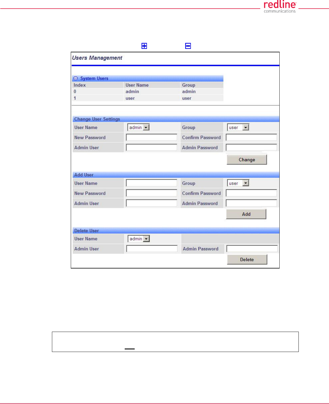
RDL-3000 User Manual
70-00158-01-DRAFT Proprietary Redline Communications © 2010 Page 88 of 142 November 25, 2010
4.7.2 Users Management
Use the Users Management screen to manage user account and passwords on the
RDL-3000. Click Utilities -> Users Management in the left hand menu to display the
System Password screen. Click to expand or to hide fields.
Fig. 57: Web - Users Management Screen
The RDL-3000 supports administrator and user accounts. See Table 4: Web -
Screens and User Access on page 42 for permissions associated with each group.
Administrators can add new user accounts and modify passwords. Usernames may be 1
to 19 alpha-numeric characters including a-z, A-Z, 0-9, dash (-), and underscore (_),
Passwords may be 8 to 15 alpha-numeric characters including a-z, A-Z, 0-9, dash (-),
and underscore (_).
Important: There must always be at least one 'administrator' account active on
the RDL-3000. You can not manage the RDL-3000 if all accounts are 'user'.
Note: When user authentication is set to RADIUS Only or Local + RADIUS, the
authorization data is retrieved from the RADIUS server at ten minute intervals. For
example, if a user's authorization is changed on the RADIUS server, it may be up to ten
minutes (max.) before the RDL-3000 is updated.

RDL-3000 User Manual
70-00158-01-DRAFT Proprietary Redline Communications © 2010 Page 89 of 142 November 25, 2010
System Users
User Name: User-assigned login name for this user.
Group: Select a group for the new user account. See Table 4: Web - Screens and User
Access table.
Change User Settings
Use these controls to change the settings for an existing account.
User name: Select the existing user account to be modified.
Group: Select the group to be associated with this username (optional).
New Password: Enter the new user password for this account (optional).
Confirm Password: Re-enter new user password (if changing user password).
Admin User: Enter the name of the administrator authorizing this change.
Admin Password: Enter the administrator password.
Change: Click to activate and permanently save changes.
Add User
Use these controls to create a new account.
Name: Enter a name for the new user account.
New Password: Enter a password for the new account.
Confirm Password: Re-enter the password for the new account.
Admin User: Enter the name of the administrator authorizing this change.
Admin Password: Enter the administrator password.
Add: Click to activate the new account and permanently save changes.
Delete User
Use these controls to delete an existing user.
User name: Select an existing user account.
Admin User: Enter the name of the administrator authorizing this change.
Admin Password: Enter the administrator password.
Del: Click to delete user and permanently save changes.
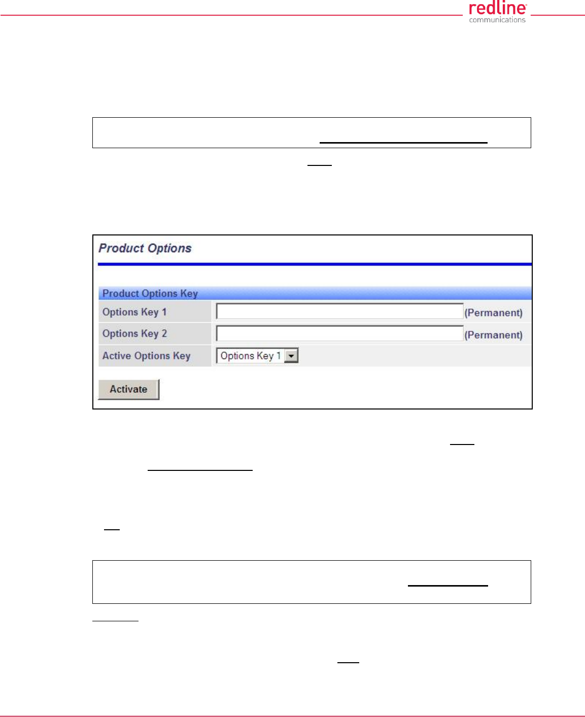
RDL-3000 User Manual
70-00158-01-DRAFT Proprietary Redline Communications © 2010 Page 90 of 142 November 25, 2010
4.7.3 Product Options
Click Utilities -> Product Options in the left hand menu to display the Product Options
screen. The options keys (a string of numbers, letters, and dashes) enable RDL-3000
features including the maximum uncoded burst rate and frequency ranges (See 8.3:
Regional Codes on page 138). Options key are unique to a specific RDL-3000 (keyed to
MAC address).
Important: If the RDL-3000 is placed in-Service without entering a purchased
permanent Options Key, the wireless link will experience Service outages.
At least one valid permanent options key must be purchased and installed before the
RDL-3000 is placed in-Service. A second options key (permanent or temporary key) may
be added to trial new options without deleting the current key. Advance notice is
provided when a temporary options key is about to expire. If the temporary options key is
selected as the active key, a message is logged and an SNMP trap is generated every 6
hours during the last five days of operation.
Fig. 58: Web - Product Options Screen
Options Key 1: Enter a valid permanent key. A permanent Options Key must be entered
for in-Service operation. The temporary options key shipped with the RDL-3000 will
expire and Service is interrupted.
Options Key 2: Enter a second valid permanent or temporary options key (optional).
Active Options Key: The Active Options Key field selects the preferred key. If valid, the
selected key is activated immediately when the Activate button is clicked. This selection
is not affected by switching firmware versions. If the (temporary) active key expires, the
RDL-3000 will attempt to remain operational by automatically switching to the other key
(e.g., permanent key).
Important: Always enter and activate a purchased permanent options key before
testing temporary keys -- otherwise you will experience a Service outage on the
wireless link when the temporary key expires.
Controls
Activate: Click to validate and activate options key(s). Invalid keys are discarded and an
error message is recorded in the event log. If two keys are entered in the same session
(before clicking Activate), keys are saved only if both keys are valid. When each key is
validated, the key 'type' is displayed adjacent to the key indicating either 'Permanent' or
'Temporary'.
RDL-3000 User Manual
70-00158-01-DRAFT Proprietary Redline Communications © 2010 Page 91 of 142 November 25, 2010
The RDL-3000 has the following default settings when operating with no option key:
Table 8: Defaults with No Options Key
System
SNMP
V2
VLAN for Data (Classification)
Disabled
VLAN for Management
Disabled
Wireless
System Mode
PMP SS Only
Channel Width
10 MHz
RF Freq.
T502 radio (MHz): 3300-3800, 3650-3700, 4400-
5000, 4940-4990, 5150-5250, 5495-5600, 5650-
5725, 5725-5795, 5815-5850
Auto Scan
Disabled
Tx Power
10 dBm max.
DFS
Permanently Enabled
Security
AES
Disabled
Secure Management:
HTTPS, SSH, SNMPv3
Disabled
X.509 Authentication
Disabled
Provisioning.
No of Subscribers
0
Max UL/DL UBR
3 Mbps
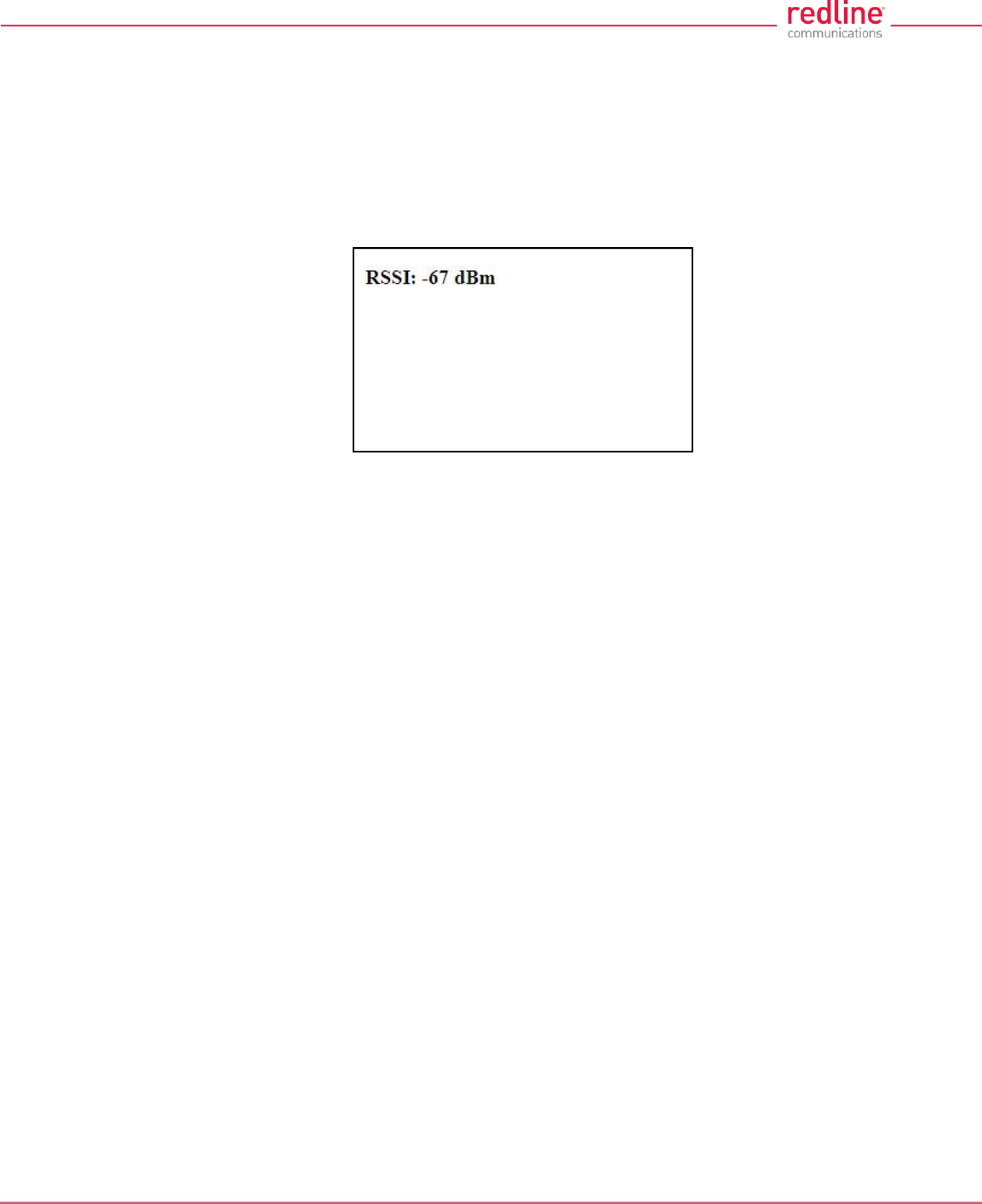
RDL-3000 User Manual
70-00158-01-DRAFT Proprietary Redline Communications © 2010 Page 92 of 142 November 25, 2010
4.7.4 Antenna Alignment Screen
Click Utilities -> Antenna Alignment in the main menu to display the Antenna
Alignment Tool screen. This screen is used to assist when aligning the subscriber
antenna.
The most reliable method for obtaining optimum performance from a wireless link is by
fine alignment of the antenna to the position providing the highest RSSI (Received
Signal Strength Indication). This web page assists alignment by providing continuous
updates of the current measured RSSI value.
Fig. 59: Web - Antenna Alignment Tool Screen
If Wi-Fi service is available, you may also be able to access the web alignment page
directly from a laptop computer and most web-enabled handheld devices using the
following URL:
http:// [RDL-3000 IP Address] / usr / aa.html
For example: http:// 192.168.20.25 / usr / aa.html
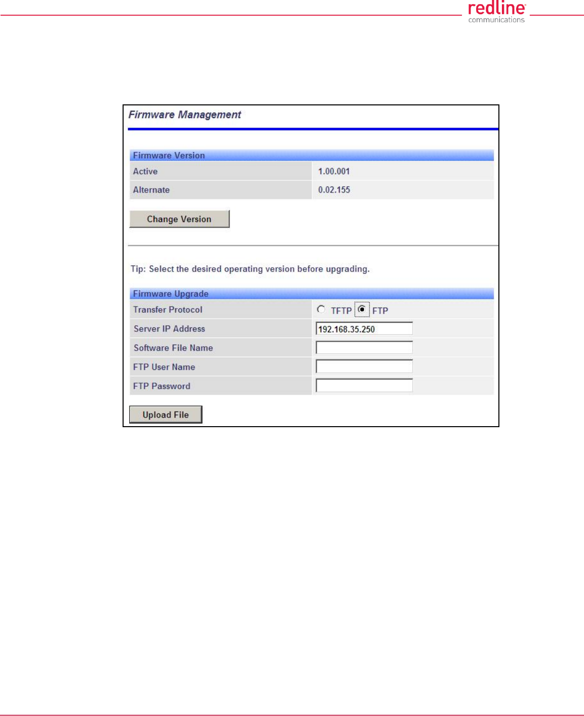
RDL-3000 User Manual
70-00158-01-DRAFT Proprietary Redline Communications © 2010 Page 93 of 142 November 25, 2010
4.7.5 Firmware Management Screen
Click Utilities -> Firmware in the main menu to display the Firmware Management
screen. This screen is used to upgrade the RDL-3000 with new firmware. The RDL-3000
contains non-volatile storage for two versions of the firmware. The upload overwrites the
Alternative (inactive) version.
Fig. 60: Web - Firmware Management Screen
Firmware Version
Active: This is the firmware currently in use by the RDL-3000.
Alternative: This is the inactive firmware. Firmware downloaded to the RDL-3000 will
overwrite this version.
Change Version: Click to switch the Active and Alternative firmware versions and
reboot the RDL-3000.
Firmware Upgrade
Transfer Protocol: Select the type of file server:
TFTP: Use Trivial File Transfer Protocol for file upload.
FTP: Use File Transfer Protocol for file upload.
Server IP Address: Enter the IP address of the computer with the firmware upgrade file.
The designated computer must be running a TFTP/FTP server.
Firmware File Name: Name of the firmware binary file (including file extension).
FTP User Name: Enter the user account name on the FTP server (FTP only).
FTP Password: Enter the password for the user account name on the FTP server (FTP
only).

RDL-3000 User Manual
70-00158-01-DRAFT Proprietary Redline Communications © 2010 Page 94 of 142 November 25, 2010
Upgrade Steps
Important; The RDL-3000 firmware binary file must be located in the default upload
directory of the TFTP/FTP server.
1. Login to the RDL-3000 Web interface and click Utilities -> Firmware in the main
menu.
2. Select TFTP or FTP, enter the IP Address of the server, and enter the full name of
the binary file (including the .bin extension). If FTP is selected, enter account name
and password.
3. Click Upload File to begin the file transfer. The transfer may require up to eight
minutes based on the data transfer rate. Do not interrupt the transfer process.
When the transfer is complete, the RDL-3000 checks the integrity of the uploaded file
and registers a status message in the event log. If errors were introduced during the
transfer process, the firmware file is discarded and the upload must be repeated.
4. When the transfer has completed successfully, click the Change Version button to
select the firmware version to load on the next system reboot.
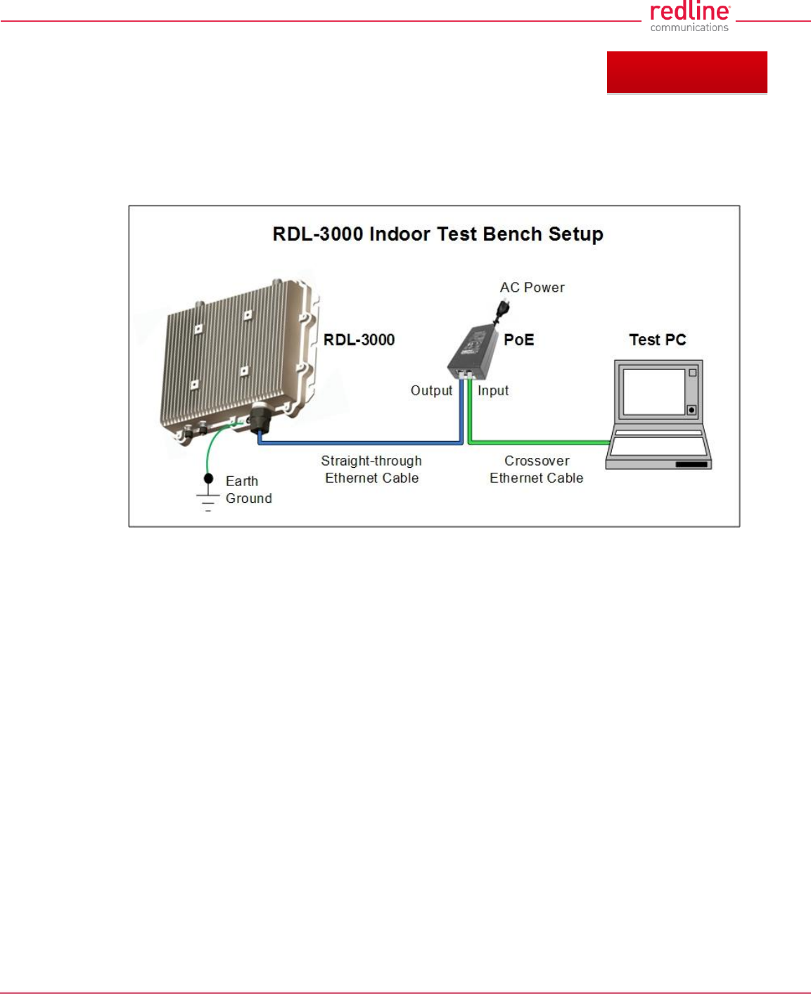
RDL-3000 User Manual
70-00158-01-DRAFT Proprietary Redline Communications © 2010 Page 95 of 142 November 25, 2010
5 CLI Interface
This section describes the procedures for configuring and operating the RDL-3000 using
CLI over a Telnet connection. The following procedures require a PC equipped with a
Web browser, Ethernet port, and an Ethernet Cat-5e crossover cable for connection to
the PoE power adapter.
Fig. 61: Telnet - Connecting a PC to the RDL-3000
The IP address and subnet mask of the PC must be on the same subnet as the RDL-
3000.
For example: IP address = 192.168.25.11, Net Mask = 255.255.255.0
5.1 Telnet Access
Use the following steps to establish a Telnet session with the RDL-3000. Refer to the
RDL-3000 User Manual section 5: CLI Interface for a complete description of the
available commands.
1. On the PC, open a Telnet client and enter the unit IP address. The factory default IP is
'192.168.25.2'.
2. Login to the RDL-3000 using the assigned username and password. The default username is
'admin', and the default password is 'admin'.
For example,
telnet 192.168.25.2
username: admin
password: admin
5.2 Command Summary
Online help is available for all commands, and the Tab key can be used for auto-
complete functions. The following table lists all RDL-3000 commands available from root
mode (default mode when you login).
Chapter 5
RDL-3000 User Manual
70-00158-01-DRAFT Proprietary Redline Communications © 2010 Page 96 of 142 November 25, 2010
Table 9: CLI - Command Summary
Command
Description
apply
Activate changes without overwriting saved configuration.
arp
Add static ARP definitions to the RDL-3000 ARP table.
chgver
Change default version of firmware and reboot.
clear
Clear commands.
del
Delete an ID.
enable
Enable an ID.
freq
Enter frequency ranges for autoscan and DFS.
generate
Create DSA key for SSH locally on RDL-3000.
get
Display the value of a statistic or parameter.
load
Load commands.
logout
End the current Telnet session.
new
Create a new ID.
ping
Send a ping message from the RDL-3000 system.
reboot
Reboot the RDL-3000.
reset
Reset the RDL-3000 statistics values.
save
Save the selected configuration settings.
script
Generate a configuration script.
set
View/modify a system parameter value.
show
View system compound objects (e.g., configuration).
snmpcommunity
View/modify the SNMP community settings.
snmptrap
View/modify the SNMP trap settings.
upgrade
Upload a firmware binary image to the RDL-3000.
user
View/modify the user/password configuration.
whoami
Display login name for this Telnet session.
Table 10: CLI - Root Mode Commands
Command
Description
Tab
When entering a command, hit the Tab key at any time to perform auto-
complete or view available options.
?
Use the '?' character to display help for any command or mode.
Example: From the root directory, enter the following command to list all
parameters that can be changed using the 'set' command:
set ?
CTRL-Z
Return to root mode.
Cancel command entry (alternative to backspace delete).
exit
Return to parent node / mode.
all (exit all) Return to root mode.
logout
Terminate this telnet session. May be entered from any mode.
RDL-3000 User Manual
70-00158-01-DRAFT Proprietary Redline Communications © 2010 Page 97 of 142 November 25, 2010
5.3 Command Set
5.3.1 apply
Use the apply command to activate changes to the configuration without overwriting the
last saved configuration. This is equivalent to clicking the Apply button in the
configuration screens.
Table 11: CLI - arp
apply <config>
config
Activate all changes to the configuration, but do not save changes permanently in the
non volatile RAM.
Note: Use this command in combination with reboot to temporarily test changes to the
configuration. For example:
5.3.2 arp
Use the arp command to manually (e.g., for wireless link aggregation). A maximum of
two static (persistent) entries can be added to the table. Use the 'save config' command
to permanently save changes to the static entries in the ARP table. Static entries loaded
at boot time are recorded in the RDL-3000 system log.
Table 12: CLI - arp
arp <add> <del> <print>
add <Host> <MAC>
Add a new static entry in the RDL-3000 ARP table. Use 'save config' to save these
entries permanently. A maximum of two static entries can be added to the table.
Host Host IP address. Must be same subnet as RDL-3000 unit.
MAC Host MAC address (e.g., 01-02-03-04-05-06)
del <Host>
Delete a static or dynamic entry from the ARP table. Also see command 'clear arptable'.
Host: Host IP address of ARP entry to be deleted
print
Print the ARP table. The * indicates manually entered values.
For example:
192.168.25.12# arp print
192.168.25.1 at 00:05:5d:e0:5b:10
192.168.25.22 at 11:22:33:44:55:66 *
192.168.25.33 at 01:02:03:04:05:06 *
192.168.25.201 at 00:05:5d:e0:5b:10
Persistent MACs:
192.168.25.22 at 11:22:33:44:55:66
192.168.25.33 at 01:02:03:04:05:06
RDL-3000 User Manual
70-00158-01-DRAFT Proprietary Redline Communications © 2010 Page 98 of 142 November 25, 2010
5.3.3 chgver
Use the chgver command to change the firmware version loaded when the RDL-3000 is
rebooted.
Table 13: CLI - chgver
Use this command to switch to alternate firmware version.
chgver (no options)
Switch to the binary saved in the alternate version of firmware. This command works silently
(no operator confirmation) and the RDL-3000 reboots immediately.
Note: Use 'get swver' to list the active and alternate versions of firmware.
5.3.4 clear
Use the clear command to delete all entries in a table.
Table 14: CLI - clear
Enter this command to delete all contents from a data structure.
clear <arptable> <freqlist> <idtable> <log>
arptable
Delete all static entries in the ARP table (refer to arp).
freqlist
Delete all frequency ranges from list (refer to 'freq' command).
idtable
Delete all IDs from the idtable.
log
Delete all messages from the log.
5.3.5 del
Use the del command to delete a specific ID or security key/certificate.
Table 15: CLI - del
Delete file information from the RDL-3000 non-volatile memory.
del <file> <folder> <id>
file <name> <mode>
Remove a file from runtime memory and non volatile RAM.
name <filename>
File name must be of the following format:
dsa_key_<mac>.pem DSA key used for SSH.
rsa_key_<mac>.pem RSA Key used for SSH.
ssl_cert_<mac>.pem SSL Certificate.
ssl_key_<mac>.pem SSL Key.
usr_wcert_<mac>.der* User wireless certificate.
usr_wkey_<mac>.der* User wireless key.
usr_wacert_<mac>.der* User wireless authority certificate.
The <mac> portion is the MAC address of the board. For example: dsa_key_00-
09-02-00-01-02.pem
mode <usr | factory | fips>
Specify the type of information to display.
RDL-3000 User Manual
70-00158-01-DRAFT Proprietary Redline Communications © 2010 Page 99 of 142 November 25, 2010
Table 15: CLI - del
usr User entered files (default if type is not specified).
factory Factory default files (requires hardware jumper selection).
fips FIPS mode files.
id <id>
Remove a Service Group, Service, or Link table entry.
id Unique number for Service Group, Service, or Link.
folder <usr | factory | fips>
Remove all files from the specified table.
usr - User entered files (default).
factory - Factory use only.
fip - FIPS mode files.
5.3.6 enable
Use the enable command to enable a specific ID (that was disabled).
Table 16: CLI - enable
Enable a Service Group, Service, or Link id.
enable <id>
Enable a specific ID.
id Unique number for Service Group, Service, or Link.
5.3.7 freq
Use the freq command to configure frequency ranges when using autoscan or DFS.
Table 17: CLI - freq
freq <add> <clearall> <del> <print> <reload>
add <begin> <end>
Add a frequency range (up to 32 ranges).
begin - start frequency (MHz)
end - end frequency (MHz)
clearall
Delete all entries from the frequency list.
del <idx>
Delete a frequency validation range
idx - Frequency validation range index. Use 'print' to display IDs.
print
Print the list of frequency ranges.
Local frequency ranges:
index begin end
-------------------------------
0 5810.0 5820.0
1 5830.0 5835.0
reload
Reload the active list of frequency validation ranges.
RDL-3000 User Manual
70-00158-01-DRAFT Proprietary Redline Communications © 2010 Page 100 of 142 November 25, 2010
5.3.8 generate
Use the generate command to generate a DSA key for use with SSH. The generated
key is saved in runtime memory and non volatile RAM.
Table 18: CLI - generate
Use the built-in utility to create SSH keys.
generate <sshkey>
The RDL-3000 will generate a key using its internal encryption engine.
sshkey <dsa | rsa>
dsa Generate DSA key for SSH.
rsa Generate RSA key for SSH.
Note: A system reboot is required to activate the new key.
5.3.9 get
Use the get command to view system parameters. Use the following general format to
view a parameter.
Table 19: CLI - get
Display parameters.
get <parameter>
activeids
Number of active IDs (Services, Service Groups, and Links).
activelinks
Number of active Links.
dldpkt
Number of downlink discarded packets.
dloir <id>
Get the downlink offered information rate for the service.
dlrpkt
Number of downlink Rx packets.
dltpkt
Downlink Tx packets.
erxpkt
Number of Ethernet packets received.
erxpktd
Number of Ethernet packets received that were discarded.
ethsts
Speed and duplex settings for the Ethernet port.
etxpkt
Number of Ethernet packets transmitted.
grpoir <id>
Get the Offered Information Rate (OIR) for the specified service Group.
id Index value of the Service Group
idenable <id>
Check the status of a Link, Service Group, or Service.
RDL-3000 User Manual
70-00158-01-DRAFT Proprietary Redline Communications © 2010 Page 101 of 142 November 25, 2010
Table 19: CLI - get
off = Link, Service Group, or Service is disabled (use enable to activate).
on = Link, Service Group, or Service is active (enabled).
lactive <id>
Link active status.
ldlblk
Downlink total blocks.
ldlbr
Downlink burst rate.
ldldblk
Downlink discarded blocks.
ldllfr
Downlink lost frames.
ldlrblk
Downlink retransmitted blocks.
ldlrssi
Downlink RSSI.
ldlsnr
Downlink SINADR.
llostc
Wireless link lost.
lrcon
Number of Services provisioned on this Link.
lrsrv
Number of links with registered service connections.
lscode
Link status code.
lulblk
Uplink total blocks.
lulbr
Uplink burst rate.
luldblk
Uplink discarded blocks.
lullfr
Uplink lost frames.
lulrblk
Uplink retransmitted blocks.
lulrssi
Uplink RSSI.
lulsnr
Uplink SINADR.
luptime

RDL-3000 User Manual
70-00158-01-DRAFT Proprietary Redline Communications © 2010 Page 102 of 142 November 25, 2010
Table 19: CLI - get
Link up-time.
mac
RDL-3000 MAC address.
radiotype
Radio type.
regconn
Number of configured connections. (?)
regsrv
Number of configured Services.
regstations
Number of configured stations.
rffreq
RF frequency setting.
rfstatus
Status RF transmitter.
swver
List the downloaded firmware versions.
sysstarttime
Time when the system started.
sysuptime
Time elapsed from reboot.
temperature
Internal temperature of the radio.
txpower
Current Tx power setting.
uldpkt
Uplink discarded packets.
uloir <id>
Get the uplink offered information rate (OIR) for the service.
ulrpkt
Uplink Rx packets.
ultpkt
Uplink Tx packets.
werxpkt
Wireless Eth Rx packets.
werxpktdis
Wireless Eth Rx discarded packets.
werxpkterr
Wireless Eth Rx packets with errors.
wetxpkt
Wireless Eth Tx packets.
RDL-3000 User Manual
70-00158-01-DRAFT Proprietary Redline Communications © 2010 Page 103 of 142 November 25, 2010
Table 19: CLI - get
wetxpktdis
Wireless Eth Tx discarded packets.
wetxpkterr
Wireless Eth Tx packets with errors.
5.3.10 load
Use the load command to install encryption keys into the RDL-3000.
Table 20: CLI - load
Load stored information from non volatile RAM or a remote server.
load <file> <idtable> <script>
file <server IP> <filename> <usr | factory | fips> <tftp | sftp> <user> <password>
Load a key or certificate file from FTP server. The file is saved in non volatile RAM area. A
reboot is required to activate changes to security data. The filename must be one of the
following:
dsa_key_<mac>.pem DSA key used for SSH.
rsa_key_<mac>.pem* RSA Key used for SSH.
ssl_cert_<mac>.pem SSL Certificate.
ssl_key_<mac>.pem SSL Key.
usr_wcert_<mac>.der** User wireless certificate.
usr_wkey_<mac>.der User wireless key.
usr_wacert_<mac>.der User wireless authority certificate.
The <mac> portion is the MAC address of the board.
For example: dsa_key_00-09-02-00-01-02.pem
Specify where to store the security information.
usr User entered files (default if type is not specified).
factory Default files.
fips FIPS mode files (FIPS mode must be active).
For example:
load file 192.168.25.10 ssl_key_00-09-02-00-b2-73.pem usr tftp
idtable (no parameters)
Load all IDs from flash memory. This can be used to restore all IDs from the last saved
configuration.
script <server IP> <filename>
Use this command to load the RDL-3000 configuration information from a file (created
using script command) located on a remote TFTP server. The file must be located in the
TFTP default directory. The 'save config' command must be used to save the loaded
configuration in non volatile memory. A reboot may be required to activate the loaded
configuration settings.
For example:
load script 192.168.25.10 RDL3000-Unit035-091121.cfg
RDL-3000 User Manual
70-00158-01-DRAFT Proprietary Redline Communications © 2010 Page 104 of 142 November 25, 2010
5.3.11 logout
Use the logout command to terminate the current Telnet session.
Table 21: CLI - logout
End the current Telnet session.
logout
Terminate the current Telnet session (no parameters).
5.3.12 new
Use the new command to create a new Service Group, Service, or Link.
Table 22: CLI - new
Create a new Service Group, Service, or Link.
new <conn> <group> <link>
conn <id>
Create a new Service.
id - Specify a unique ID for this connection:
group <id>
Create a new Service Group.
id - Specify a unique ID for this Service Group:
link <id>
Create a new Link.
id - Specify a unique ID for this Link:
5.3.13 ping
Use the ping command to initiate an ICMP ping command from the RDL-3000.
Table 23: CLI - ping
Send an ICMP ping command. This can be used to confirm network access to FTP/TFTP
servers, syslog servers, etc.
ping <IP address> <Number of Packets>
IP address IP address of target.
Number of Packets Number of ICMP packets to send (1 to 16).
5.3.14 reboot
Use the reboot command to reboot the RDL-3000 firmware.
Table 24: CLI - reboot
Command the RDL-3000 to reboot. Entering 0 (zero) cancels reboot in-progress.
reboot <seconds>
seconds Number of seconds to wait before rebooting.
Note: Use this command in combination with Apply to temporarily test changes to the
configuration. For example:
set radio rf1 rf2 Modify desired parameter
reboot 600 Schedule reboot in 5 minutes
apply Activate configuration changes (without saving)
(5 min later) RDL-3000 reboots and loads saved configuration
5.3.15 reset
Use the reset command to zero the RDL-3000 statistics or ID table.
RDL-3000 User Manual
70-00158-01-DRAFT Proprietary Redline Communications © 2010 Page 105 of 142 November 25, 2010
Table 25: CLI - reset
Reset RDL-3000 values.
reset <stats>
Enter ID of specific Service, Service Group, or Link to be reset.
stats <id>
Reset statistics for a Service Group, Service, or Link.
id - Specify an ID to reset statistics only for that Service Group, Service, or Link.
Default is to reset all statistics.
5.3.16 save
Use the save command to copy edited parameter settings into non-volatile memory.
save [option] <Enter>
Table 26: CLI - save
Copy parameters to non-volatile memory. Does not affect security settings.
save <config> <defaultconfig> <idtable> <snmp>
config
Save Ethernet, wireless, and user configuration settings.
defaultconfig
Overwrite parameters with the factory default settings. The following settings are not
affected: system name, location, details and contact, frequency list, SNMP configuration,
Idtable.
idtable
Save current idtable settings.
snmp
Save current SNMP settings.
5.3.17 script
Use the script command to save a file containing a string of Commands that can be
used to restore the current (active) configuration of the RDL-3000. Saved configuration
files can be viewed, copied, and/or modified using a text editor.
The file is saved in the TFTP default directory. The filename may be any name and
extension valid for the TFTP server platform. It is recommended use a filename that
uniquely identifies the RDL-3000 unit and the current date (e.g., Red80-AD0023-
080723.cfg). See 'load' command.
Table 27: CLI - script
Create and save a script file containing all configuration settings.
script <server> <name>
server - TFTP server IP address
name - Script file name
Note: User account groups, usernames and passwords are not saved by the script
command. Accounts must be created manually by a user using Telnet or a Web
browser. The 'user' commands are interactive and can not be automated.
RDL-3000 User Manual
70-00158-01-DRAFT Proprietary Redline Communications © 2010 Page 106 of 142 November 25, 2010
5.3.18 set
Use the set command to view and/or change a parameter. Use the apply command to
activate changes made using the set command. Use the save command to permanently
save changes (to non volatile RAM).
Table 28: CLI - set
View and change general parameter settings.
set <parameter>
activekey <1 | 2> <key>
Select the active options key (position 1 or 2). Advance notice is provided when a
temporary options key is about to expire. If the temporary options key is
selected as the active key, a message is logged and an SNMP trap is
generated every 6 hours during the last five days of operation.
key - Optionally enter a new key value.
adaptmod <off | on>
Enable or disable the adaptive modulation function.
off - Disable
on - Enable
antgain <gain>
Set the antenna gain (used for DFS).
<gain> Enter gain in dBm.
autoscan <off | on>
Enable or disable the Autoscan function.
off - Disable
on - Enable
When enabled, the Subscriber automatically scans available channels to locate
the current operating frequency.
bsmac <00:00:00:00:00:00 | mac_address>
If set to a non-zero value, the subscriber is allowed to connect only to this base station
with this MAC address (may use '-' or ':' for separators).
bsporten <id> <off | on>
Enable and disable sector controller Ethernet port.
id - ID of port
off - Disabled
on - Enabled
buzzer <off | on>
Enable or disable the audible alignment buzzer.
off - Disable
on - Enable
When enabled, the rate of the tone is proportional to the receive signal strength
(faster rate = stronger signal).
chsize <bandwidth>
Enter the channel bandwidth (enabled by options key).
bandwidth Enter bandwidth in MHz (e.g., 20).
congid <id> <gid>
Assign a Service Group to this Service.

RDL-3000 User Manual
70-00158-01-DRAFT Proprietary Redline Communications © 2010 Page 107 of 142 November 25, 2010
Table 28: CLI - set
id - Service ID number.
gid - Service Group ID number.
conlid <id> <lid>
Assign a Link to this Service.
id - Service ID number.
lid - Link ID number.
conpri <id> <0 - 7>
Service default priority.
convid <id> <1 - 4095>
Set or show Service VLAN ID
id - Service reference ID number.
conviden <id> <off | on>
Enable or disable VLAN connections.
id - Service ID number.
on - VLAN is enabled.
off - VLAN is disabled.
dfsaction <none | txoff | chgfreq>
Select the mode of operation for DFS.
None (0): The DFS function is disabled.
Tx Off (1): Transmission is immediately disabled when radar signals are
detected. This action is recorded in the message log and an SNMP trap
message is sent (if SNMP enabled).
Chg Freq (2): Relocate transmission to an alternative frequency immediately
when radar signals are detected. This action is recorded in the message log
and a trap message is sent (if SNMP enabled).
dlminrate <id> <1 - 54>
Link minimum downlink uncoded burst rate (Mbps). Entry values are dependent on the
channel bandwidth (chsize).
id = Link ID number.
dlcir <id> <50 - 50000>
Service downlink committed information rate (CIR) (Kbps).
id - Service ID number.
dlpir <id> <50 - 50000>
Service downlink peak information rate (PIR) (Kbps).
id - Service ID number.
dlrate <id> <6 - 54>
Link maximum downlink uncoded burst rate.
id = Link ID number.
dlratio <20-80>
Set the downlink ratio.
encmode <0 - 4>
Set the encryption mode. The same encryption level must be selected on
communicating systems.
0 - Disable

RDL-3000 User Manual
70-00158-01-DRAFT Proprietary Redline Communications © 2010 Page 108 of 142 November 25, 2010
Table 28: CLI - set
1 - 64-bit (Redline)
2 - AES 128
3 - AES 192
4 - AES 256
ethmode <auto | 10hd | 10fd | 100 fd | 100hd>
Enter a value for the combined Ethernet speed and duplex.
auto - Auto-negotiate
10hd - 10Base-T Half Duplex
10fd - 10Base-T Full Duplex
100hd - 100Base-T Half Duplex
100fd - 100Base-T Full Duplex
fastreg <off | on>
Fast registration mode.
id - Service reference ID number.
fixframe <off|on>
Configure the fixed frame mode.
off - Use dynamic frames based on traffic patterns.
on - Wireless frames are fixed at the size specified in the framesize field.
framesize <size>
When Fixed Frame is enabled, enter the frame size in milliseconds.
size - Enter the fixed frame size (ms).
gateway <ip>
Enter the IP address of the default gateway on this segment.
gmt <value>
Enter the time offset from GMT (e.g., -5 for EST).
grpcir <id> <50 - 50000>
Service Group Committed Information Rate (CIR) for downlink broadcast and multicast
traffic.
id - Group ID number.
grppir <id> <50 - 50000>
Service Group peak information rate (PIR) (Kbps). Applies to uplink and downlink
traffic.
id - Group ID number.
grprate <id> <6 - 54>
Service Group maximum rate (Mbps). Applies to uplink and downlink.
id - Group reference ID number.
grppri <id> <pri>
Service Group default priority.
id - Group reference ID number.
pri - Group 802.1p priority setting (0-7).
grpvid <id> <vid>
Display/set the value of the VLAN ID for this Service Group.
id - [id number]

RDL-3000 User Manual
70-00158-01-DRAFT Proprietary Redline Communications © 2010 Page 109 of 142 November 25, 2010
Table 28: CLI - set
vid - VLAN ID
grpviden <id> <off | on>
Display the status or enable/disable this Service Group.
id - [id number]
off - Disabled
on -Enabled
http <off | on>
Enable or disable the HTTP function. When disabled, the Web interface will not be
available.
off - Disable
on - Enable
https <off | on>
Enable or disable the HTTPS function.
off - Disable
on - Enable
idname <id> <name>
View or modify the name associated with an ID.
id - ID for Link, Service, or Service Group.
name - Name (maximum 15 text characters).
ipaddr <ip> <mask>
Enter the IP address and subnet mask of the RDL-3000. Confirmation is required.
Example:
set ipaddr ip 192.168.100.10 mask 255.255.255.0
ldlpir <id> <50-50000>
Link downlink PIR.
id = Link ID number.
lulpir <id> <50-50000>
Link uplink PIR.
id = Link ID number.
maxdst <distance>
Maximum distance to a subscriber.
value - Distance (Km) to farthest subscriber.
maxtxpower <-10 - 25>
Enter the Tx power level (dBm). This setting is for the transceiver output only. The
actual EIRP depends on the gain of the connected antenna. The maximum
value is determined by the options key.
mgmtag <off | on>
Enable or disable the HTTPS function. See also mgmvid.
off - Do not use VLAN to identify management traffic.
on - Enable VLAN tagged management traffic. See mgmvid.
mgmvid <1 - 4095>
Specify Management VLAN ID. See also mgmtag.
vlan_id - Management VLAN ID.
RDL-3000 User Manual
70-00158-01-DRAFT Proprietary Redline Communications © 2010 Page 110 of 142 November 25, 2010
Table 28: CLI - set
netmask <mask>
RDL-3000 IP netmask in standard format.
For example: set netmask 255.255.255.0
optionskey <key> <1 | 2>
Enter the options key string followed by the key position (0 or 1). This command works
silently to validate, save, and activate the key. Event messages are logged for each of
these operations. Enter the 'show log' command to view event messages.
peermac <MAC>
MAC address of the communicating RDL-3000. Required for wireless encryption. Use
form: aa:bb:cc:dd:ee:ff
pskey <key>
Pre-shared key.
radio <off/ rf1 / rf2 / rf1 rf2 / rf2 rf1>
Enable or disable the radio transmitter.
off - Disable both radios
rf1: only radio 1 is used
rf2: only radio 2 is used
rf1 rf2: both radios receive, only radio 1 transmits
rf2 rf1: both radios receive, only radio 2 transmits
radius <ip | mode | port | retries | secret | timeout>
Configure the RADIUS server (allowed in FIPS mode).
The first parameter for all commands must be the radius server identifier (1 or 2):
ip <1 | 2> <IP address>
IP address of RADIUS server.
1 - Primary RADIUS server.
2 - Secondary RADIUS server.
For example: Set the primary RADIUS server IP address and then set the
secondary RADIUS server IP address:
set radius ip 1 192.168.100.50
set radius ip 2 192.168.100.51
mode <1 | 2> <off | on>
Mode of RADIUS server.
off - Disable RADIUS server.
on - Enable RADIUS server.
port <1 | 2> < 1-9999 >
Listening port address on RADIUS server (default port is 1812).
retries <1 | 2> < 1-999 >
Maximum number for attempts to contact target RADIUS server.
secret <1 | 2> < text >
Password for RADIUS server. Must conform to security policy.
timeout<1 | 2> < 1- 90 >
Time to wait for response from RADIUS server (seconds).
regper <4 - 100>
The number of frames between registrations.
rffreq < 3.5 - 40>
Center frequency (MHz) for the RF channel. Sites operating in close proximity should
minimize interference by using a factor of the channel size for separation. For

RDL-3000 User Manual
70-00158-01-DRAFT Proprietary Redline Communications © 2010 Page 111 of 142 November 25, 2010
Table 28: CLI - set
example, 20 MHz channels should have >20 MHz separation.
schcycle <1-20>
The period determines the amount of data to be sent on a Service group or Service
during each scheduling cycle. Enter scheduling cycle (ms).
snmp < off | on>
SNMP enable setting.
off - Disable the SNMP agent.
on - Enable the SNMP agent.
snmptraplink < off | on>
SNMP trap message for each Link-up and Link-down event.
off - Disable the SNMP trap message.
on - Enable the SNMP trap message.
snmptraps < off | on>
Enable or disable sending all SNMP traps.
off - Disable all SNMP trap messages.
on - Enable all SNMP trap messages.
sntp < off | on>
SNTP enable setting.
off - Disable SNTP protocol support.
on - Enable SNTP protocol support.
sntpip <ip>
Enter the SNTP server IP address. Valid only if sntp is enabled.
sntppoll <1 - 24>
Enter the SNTP polling interval in hours. Enter period in hours.
ssh <off | on>
Enable or disable the SSH function.
off - Disable
on - Enable
sstoss <id> <off | on>
Status of packet routing between SSs.
id - Link ID number.
off - Disable forwarding broadcast packets from SS to SS.
on - Enable forwarding broadcast packets from SS to SS.
srvgid <id> <gid>
Assign a Service Group ID to this Service.
id - Service ID number.
gid - Service Group ID number.
srvgid <id> <lid>
Assign a Link ID to this Service.
id - Service ID number.
lid - Link ID number.
srvpri <id> <pri>
Assign a priority to this Service.

RDL-3000 User Manual
70-00158-01-DRAFT Proprietary Redline Communications © 2010 Page 112 of 142 November 25, 2010
Table 28: CLI - set
id - Service ID number.
pri - Assign a priority (0-7).
srvvid <id> <vlan_id>
Assign a VLAN ID to this Service.
id - Service ID number.
vlan_id - Service VLAN ID.
srvviden <id> <mode>
Enable/disable VLAN for this Service.
id - Service ID number.
mode - off = Pass Through, on = VLAN tagged.
syncmode < none | int : internal | ext : external >
Enable/disable VLAN for this Service.
none - Synchronization is disabled.
int - Synchronization using internal clock (or GPS if available).
ext - Synchronize to PPS port input.
syncout < off | on >
Enable/disable synchronization port (PPS).
off - Synchronization port is disabled.
on - Synchronization port is enabled.
syncterm < none | 50 | 75 >
Enable/disable VLAN for this Service.
none - High impedance.
50 - Port termination impedance is 50 Ohms.
75 - Port termination impedance is 75 Ohms.
syscontact <text>
Enter contact descriptive for this RDL-3000. Enter up to thirty (30) alpha-numeric
characters including a-z, A-Z, 0-9, dash (-), and underscore (_).
sysdescr <text>
Enter system description for this RDL-3000. Enter up to thirty (30) alpha-numeric
characters including a-z, A-Z, 0-9, dash (-), and underscore (_).
sysloc <location>
Enter location description for this RDL-3000 location. Enter up to thirty (30) alpha-
numeric characters including a-z, A-Z, 0-9, dash (-), and underscore (_).
syslog <off | on>
Syslog enable setting.
off - Disable syslog server protocol support.
on - Enable syslog server protocol support.
syslogip <ip>
Enter the syslog server IP address. Valid only if syslog is enabled.
sysmode <pmpsc | pmpss>
pmpsc - The sector controller (base station) begins transmitting automatically;
sending poll messages to locate the remote subscribers (pmpss).
pmpss - Subscribers wait passively, monitoring the selected channel(s) until
polled by the pmpsc (sector controller).

RDL-3000 User Manual
70-00158-01-DRAFT Proprietary Redline Communications © 2010 Page 113 of 142 November 25, 2010
Table 28: CLI - set
sysname <text>
Enter the name for this RDL-3000. Use any combination of up to 20 letters and
numbers.
telnet <off | on>
Enable or disable the Telnet port. If the Telnet port is disabled, it will not be possible to
use the CLI interface.
off - Disable
on - Enable
Changes to this field are effective only following reboot.
telnetport <1 - 65535>
Telnet port address
port - Limits for the telnet port are 22..79 and 81..65534 (default is 23).
Changes to this field are effective only following reboot.
ulcir <id> <50-50000>
Enter the uplink committed information rate for the service (Kbps).
id: -[id number]
ulminrate <id> <6 - 54>
Link minimum downlink uncoded burst rate.
id = Link ID number.
ulpir <id> <50 - 50000>
Service uplink peak information rate (PIR) (Kbps).
id - Service ID number.
ulrate <id> <1-54>
Link maximum uplink uncoded burst rate.
id = Link ID number.
usrauthmode <local> <radius>
Set the user authentication mode. Specify local services, the RADIUS server,
or both in combination.
local - use local authentication.
radius - Use the RADIUS server.
x509auth <off | on>
Enable or disable authentication.
off - Allow network registrations without authentication.
on - Require authentication using X.509 certificates.
RDL-3000 User Manual
70-00158-01-DRAFT Proprietary Redline Communications © 2010 Page 114 of 142 November 25, 2010
5.3.19 show
Use the show command to display system statistics.
Table 29: CLI - show
Display PMP system parameters and statistics.
show <config> <conns> <groups> <files> <idtable> <links> <log> <snmp> <service>
<stats>
config
Display system configuration information.
conns <id>
Display information for a Service. Default is to display all Services.
id ID of Service.
192.168.25.2(show)# conns 4
96 Data A Conn
97 Voice A Conn
files <run | usr>
Display the key and certificate files.
run - Display keys currently in use.
usr - Display the user keys and certificates (default).
groups
Display information for all Service Groups.
192.168.25.2(show)# groups
64 Voice Group
65 Data Group
idtable
Display information for all system IDs.
192.168.25.2(show)# idtable
ID Name Type Status
------------------------------------------------------
4 Sub A Link Enabled
5 Sub B Link Enabled
10 Sub C Link Enabled
15 Sub D Link Enabled
64 Voice Group Enabled
65 Data Group Enabled
96 Data A Conn Enabled
97 Voice A Conn Enabled
98 Data B Conn Enabled
99 Voice B Conn Enabled
100 Data C Conn Enabled
101 Voice C Conn Enabled
links
Display information for all Links.
192.168.25.2(show)# links
4 Sub A Link Down
5 Sub B Link Down
10 Sub C Link Down
15 Sub D Link Down
log
Display the system events log.
service
Show the list of enabled service connections.
192.168.25.2(show)# service 17
174 service1 Conn
RDL-3000 User Manual
70-00158-01-DRAFT Proprietary Redline Communications © 2010 Page 115 of 142 November 25, 2010
Table 29: CLI - show
snmp
Display the SNMP configuration.
stats
Display available statistics.
5.3.20 snmpcommunity
Use the snmpcommunity command to configure SNMP community permissions.
Table 30: CLI - snmpcommunity
Configure SNMP community permissions.
snmpcommunity <add> <clearall> <default> <del> <print>
add <name> <rights>
Add a new SNMP community to the SNMP community table. The index value is assigned
automatically. Up to eight community entries can be entered.
name
Enter the SNMP community name.
rights
Specify the rights for this community string. Where.
0: Deny read and write permission (enter zero).
r: Grant read access permission only.
w: Grant write access permission only.
rw: Grant read and write access permission.
clearall (no parameters)
Delete all SNMP parameters.
default <idx>
Set all SNMP parameters to factory default settings.
idx Specify single entry to be set to default (use 'print' command to display ids).
del <idx>
Delete the specified community entry.
idx Specify single entry to be deleted (use 'print' command to display ids).
print
List all SNMP communities and associated permissions.
5.3.21 snmptrap
Use the snmptrap command to configure the SNMP trap message reporting.
Table 31: CLI - snmptrap
Configure SNMP community trap settings.
snmptrap <add> <change> <clearall> <del> <print>
add <ipaddr> <port> <identity>
Create a new SNMP trap. The index value is assigned automatically. Up to eight settings
may be entered.
ipaddr Enter destination IP address
port Enter destination port address.
RDL-3000 User Manual
70-00158-01-DRAFT Proprietary Redline Communications © 2010 Page 116 of 142 November 25, 2010
Table 31: CLI - snmptrap
identity v2: Enter associated SNMP community string.
v3: Enter account username for authorization.
change <idx> [-p <port>] [-i <ip_add>] [-c <community>] [-u username]
Modify the specified SNMP setting.
idx Index of the SNMP trap (use 'print' command to display ids).
-i <ip_add>] Enter destination IP address.
-p <port>] Enter destination port address.
-c <community> Enter associated SNMP community string (SNMP V1 or V2).
-u <username> Enter account username for authorization (SNMP V3 only).
clearall
Delete all SNMP parameters.
del <idx>
Delete the specified SNMP trap.
idx Index of the SNMP trap to be deleted (use 'print' command to display ids).
Linkupdown
Trap indicates when the wireless Link is lost and recovered.
Off -
On -
print
List all SNMP trap settings.
5.3.22 upgrade
Use the upgrade command to upload a new firmware binary file to the RDL-3000.
Table 32: CLI - upgrade
Configure SNMP community permissions.
upgrade <ip addr> <file name> <user name> <password>
ip addr
IP address of the FTP/TFTP server.
file name
Name of the binary file to be uploaded.
user name
FTP account name (FTP server only).
password
FTP account password (FTP server only).
TFTP: You must specify the TFTP server address and the full name of the binary file (including
.bin extension). The firmware binary file must be located in the default directory of the TFTP
server.
FTP: You must specify the FTP server address, account user name, account password, and the
full name of the binary file (including .bin extension). The firmware binary file must be located in
the default directory for the specified user account.
RDL-3000 User Manual
70-00158-01-DRAFT Proprietary Redline Communications © 2010 Page 117 of 142 November 25, 2010
5.3.23 user
Use the user command to manage user accounts, passwords, and user Groups. When
in user mode, only the <chgpasswd> field is available, since the user can change only
their own password. The other commands are available only for members of the
administrator Group.
Table 33: CLI - user
Manage the user accounts.
user <add> <attr> <chgpasswd> <del> <print>
add <username> <usertype>
Administrators can use this command to add new user accounts. Usernames may be 1 to
19 alpha-numeric characters including a-z, A-Z, 0-9, dash (-), and underscore (_),
Passwords may be 8 to 15 alpha-numeric characters including a-z, A-Z, 0-9, dash (-), and
underscore (_). The operator must confirm their own password and a password for the
new account.
The RDL-3000 supports administrator and user accounts. See Table 4: Web - Screens
and User Access on page 42 for permissions associated with each group.
username Enter name of new administrator or user account.
usertype Specify the type of account being created.
user User account.
admin Administrator account.
attr <username> < none | MD5 | SHA > < none | DES | AES >
Designate an authentication method and privacy method to be used for SNMP v3
requests. An authentication method must be selected to enable usage of the privacy
method. Only combination SHA authentication + AES privacy is valid in FIPS mode.
username - Account to setup for SNMP v3 authorization.
chgpasswd <user name>
Administrators can change the password of any account. Users can change only their own
password. Users are prompted to enter new password information.
username Account to be modified.
del <username>
Delete a user account.
username Account to be deleted.
print
Display a list of user accounts.
5.3.24 whoami
Use the whoami command to display the username of the current Telnet session. This
command is not available when logged in as administrator.
Table 34: CLI - whoami
Display username for this Telnet session.
whoami
RDL-3000 User Manual
70-00158-01-DRAFT Proprietary Redline Communications © 2010 Page 118 of 142 November 25, 2010
6 Diagnostics & Troubleshooting
This section provides basic diagnostic and troubleshooting procedures to help solve
problems that may occur with the system. If the system is not operating correctly after
applying the suggestions in this section, please contact your local Redline
representative. Include the model name and serial number of the system in your
communications.
6.1 Interface Connection Issues
Attempt to login to the RDL-3000 using a Web browser. Microsoft Internet Explorer is
recommended. If the RDL-3000 does not respond by displaying the login dialog box,
check that the correct IP address is being used. The value 192.168.25.2 is the factory
default value and may have been changed during installation.
Test is to verify the IP address is reachable from the computer. Use the ping command
to test the Service between the RDL-3000 and host computer.
>ping 192.168.25.2
If the ping test is successful, the host computer was able to send and receive packets
to/from the RDL-3000. The problem may be with the Internet browser or related settings
on the host computer. Reboot the host computer to try to resolve the problem.
If the ping is unsuccessful, there may be problems using that IP address; the IP address
may be incorrect, or there may be a duplicate address. For correct operation the host
computer and the RDL-3000 must be on the same subnet. For example, if the RDL-3000
is using the factory default settings, the host computer could be set for an IP of
192.168.25.3 and a subnet mask of 255.255.255.0.
If the correct IP address of the RDL-3000 cannot be determined, it is recommended to
perform a Long Reset operation. refer to section 6.5: Long Reset (Recover from Lost
Password or IP) on page 123. The following table lists some common troubleshooting
tips for the web interface.
Table 35: Diag. - Web Interface Diagnostics
Symptom
Possible Problem
Solution
General
Information
screen is not
displayed
Incorrect IP
address and/or
Subnet Mask.
Perform a ping test from the host computer command
line. If the ping test is unsuccessful (timeout), then the
problem may be the IP address is not correct. Perform
a long reset to apply the default IP address
(192.168.25.2) and subnet Mask (255.255.255.0)
Problems with host
computer, or RDL-
3000.
If the ping is successful, reset the RDL-3000 and/or
reset the host computer.
Host PC ARP table
is incorrectly
configured
Run 'arp -d' whenever the RDL-3000 is replaced.
Check that the subnet mask for the host PC matches
the subnet mask of the RDL-3000. Verify that the host
and the RDL-3000 are set for the same subnet and
are not using a duplicate or reserved IP address.
Chapter 6
RDL-3000 User Manual
70-00158-01-DRAFT Proprietary Redline Communications © 2010 Page 119 of 142 November 25, 2010
6.2 Status Codes
The PMP status code is displayed in a series of hexadecimal characters representing
the status of different alarm conditions. The value '1' indicates the associated condition
is active. All unused bits are set to zero.
To determine the status, the hexadecimal number must be converted to binary notation.
It is recommended to use a scientific calculator that supports binary notation (e.g.,
Windows on-screen calculator). Set the mode for Hex and enter the status code.
Change the mode to binary and match active bits (1) to the PMP Status Codes table.
For example, if 'Radio Over Temperature' bit 1 and 'PLL Error' bit 4 were active, the
status code value would be Hex '12' (binary 1 0010).
Table 36: Diag. - PMP Status Code Bits
31
30
29
28
27
26
25
24
23
22
21
20
19
18
17
16
15
14
13
12
11
9
8
7
6
5
4
3
2
1
0
Table 37: Diag. - PMP Status Codes
Bit
Description
1
Radio over-temperature
4, 5, 6
PLL Errors
8
Firmware Error
16
No Ethernet packets received by the wireless MAC
17, 18, 19, 20, 21, 22,
23, 24, 25, 26, 27, 28
MAC Internal Errors
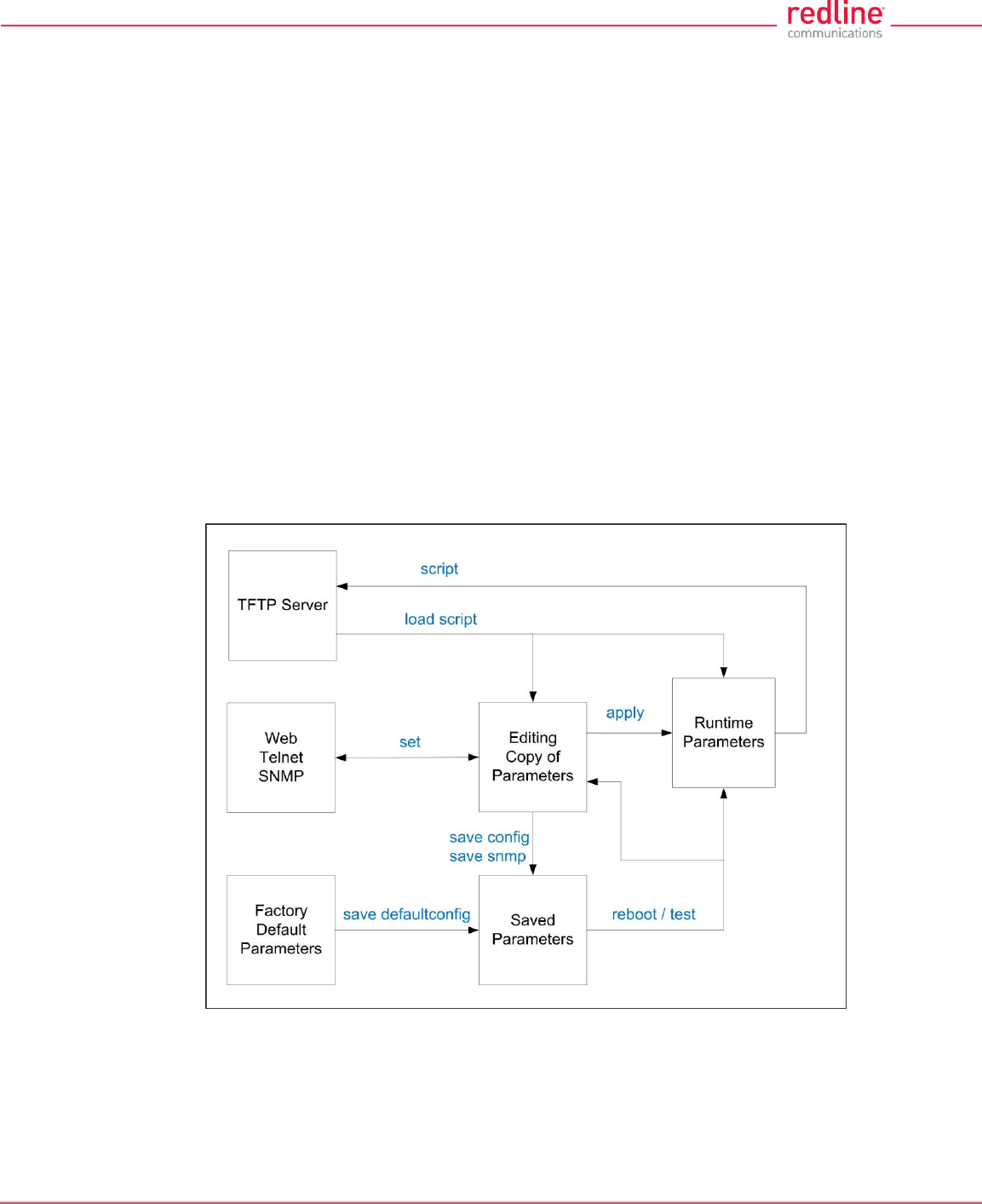
RDL-3000 User Manual
70-00158-01-DRAFT Proprietary Redline Communications © 2010 Page 120 of 142 November 25, 2010
6.3 Working with System Parameters
The RDL-3000 is a highly configurable communications device. This section describes
how to view, modify, test, and save parameter settings.
6.3.1 Parameters Overview
The RDL-3000 maintains the following sets of parameters:
Runtime Parameters Currently active system settings. These values are loaded
from 'Saved Parameters' at system reboot.
Editing Copy of Parameters These values are loaded from 'Saved Parameters' at system
reboot. The operator can use the Web or CLI interface to
modify these values. Activate changes by using the 'apply'
function. Save changes permanently by using the 'save'
functions.
Saved Parameters These values are saved in non volatile RAM and are loaded at
reboot. Use the 'save' function to overwrite the last saved
settings with the current contents of the 'Editing Copy of
Parameters'. A separate copy of Saved Parameters is
maintained for each firmware version (Active and Alternative).
Factory Default Parameters Load these settings to restore the RDL-3000 to a known state.
-
Fig. 62: Diag: - Saving Parameters in Non Volatile RAM
TFTP Server The 'Runtime Parameters' can be saved to a file on a TFTP
server. Settings are saved as CLI commands in a text file.
Saved configurations can be loaded directly from a file.
Factory Default Parameters Use this function to restore the RDL-3000 to a known state.
RDL-3000 User Manual
70-00158-01-DRAFT Proprietary Redline Communications © 2010 Page 121 of 142 November 25, 2010
6.3.2 Test Configuration Changes
The operator can use the reboot and apply functions to test changes to the configuration
that may result in loss of the wireless link. Use the following steps to test new setup
values for a five minute period and then restore the last saved configuration.
1. Make all necessary editing changes to the configuration.
2. Issue the command 'reboot 300'. This will set a timer to reboot the RDL-3000 in five
minutes (5 x 60 seconds). A longer or shorter time can also be specified.
3. Issue the 'apply' command to activate all edited changes.
4. If connectivity to the RDL-3000 is lost, wait 5 minutes for the unit to reboot
automatically and restore the previous settings.
5. If the setting are satisfactory, use 'save config' to save these settings and 'reboot 0'
to cancel the timed reboot operation.
6.4 Factory Default Settings
Use the Web interface (click Factory Defaults in main menu) or the CLI interface (save
defaultconfig) to restore the RDL-3000 to a known state.
Table 38: Diag. - Factory Default Settings
CLI Parameter
Web Field
Option
Key
Def Cfg Button Setting
System
syscontact
System Contact
Blank
sysdescr
System Details
Blank
sysloc
System Location
Blank
sysname
System Name
RDL-3000
Ethernet
ethmode
Ethernet Mode
Auto
gateway
Default Gateway Address
192.168.25.1
gmt
Time Offset
+0.00
http
HTTP Enable
On
https
HTTPS Enable
N/C
ipaddr
IP Address
192.168.25.2
mgmtag
Mgmt Tag Enable
Off
mgmvid
Mgmt VID
0
netmask
IP Subnet Mask
255.255.255.0
snmp
SNMP
V2
snmpcommunity
SNMP Community
Strings
"Public". read
"Private" read/write
snmptraplink
SNMP Traps
Off
snmptraplist
SNMP Trap List
Cleared
snmptraps
SNMP Trap Links
Off
snmpversion
SNMP Version
V2 (if SNMP enabled) 1
sntp
SNTP Enable
N/C
RDL-3000 User Manual
70-00158-01-DRAFT Proprietary Redline Communications © 2010 Page 122 of 142 November 25, 2010
Table 38: Diag. - Factory Default Settings
CLI Parameter
Web Field
Option
Key
Def Cfg Button Setting
sntpip
SNTP IP Address
192.168.25.1
sntppoll
Polling Interval
24
ssh
SSH
N/C
syslog
Sys Log Enable
Off
syslogip
Sys Log IP
192.168.25.1
telnet
Telnet Enable
On
telnetport
Telnet Port
23
userauthmode
User Authentication
Local
Wireless
antgain
Antenna Gain
30
autoscan
Autoscan
Off
chsize
Channel Size
Key = No change
No Key = 10 MHz
dfsaction
DFS Action
Y
Based on Key:
No Key = chgfreq
Required = chgfreq
Not Req = none
dlratio
Downlink Ratio
No change.
pskey
Pre-shared key
No change.
fixframe
Fixed Frame Mode
Off
framesize
Framing Cycle
1
maxdst
Max. Distance
0
radio
Radio Enable
rf1
regper
Registration Period
16
rffreq
RF Freq. (MHz)
Based on key
T502 = 5800
schcycle
Scheduling Cycle
2
syncmode
Synchronization mode
None
syncout
Sync port mode
None (port disabled)
syncterm
Sync port impedance
None (high)
sysmode
System Mode
Key = unchanged
No Key = PMP SS
txpower
Tx Power
14
Misc.
activekey
Active Key
No change
adaptmod
Adaptive
Off
arptable
No change.
buzzer
Buzzer
Off
dlcir
Service DL CIR
500
encmode
Encryption Type
Y
None
files
No change
freq
Frequency List
No change.
grpcir
Service UL CIR
500
idtable
No change
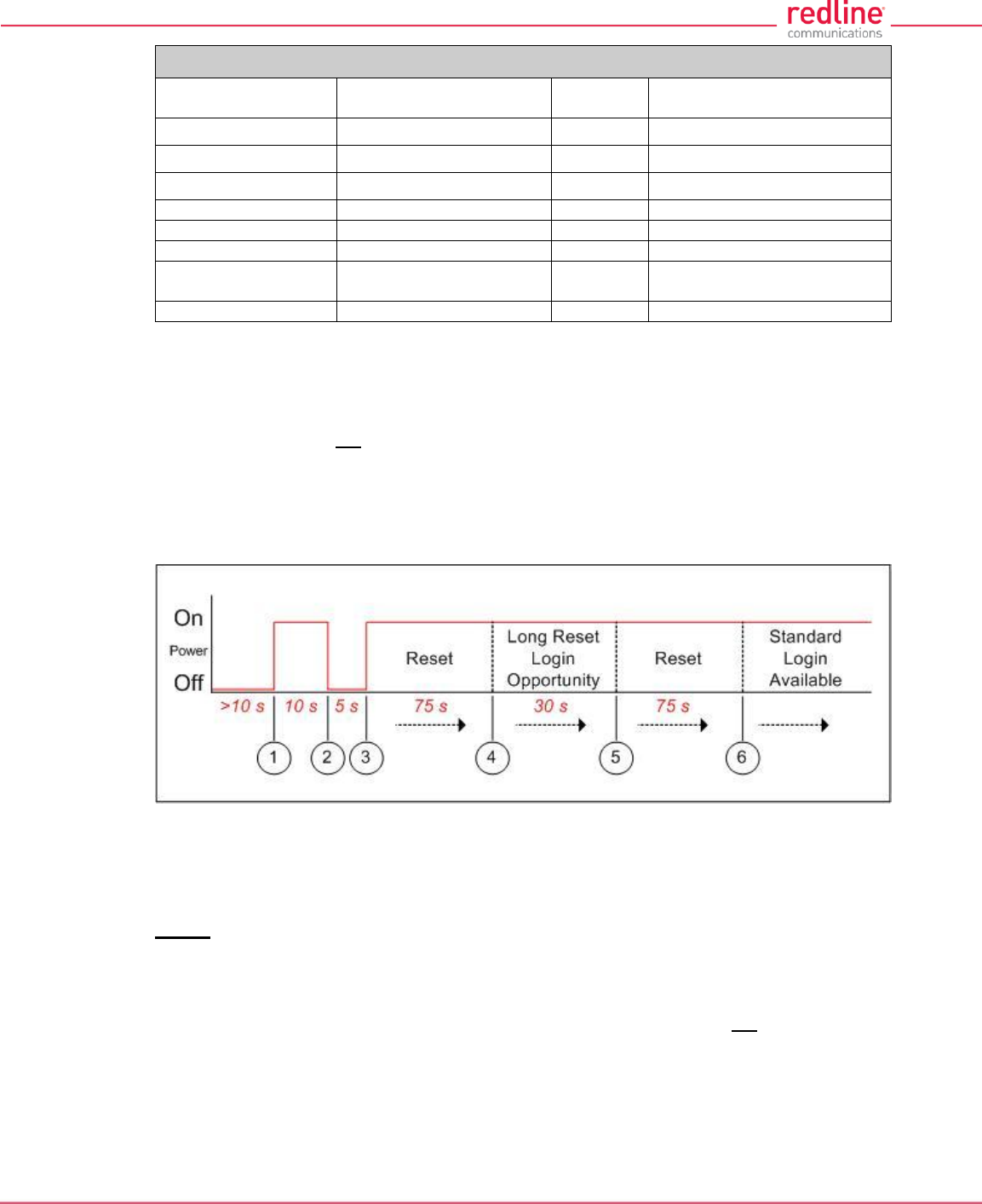
RDL-3000 User Manual
70-00158-01-DRAFT Proprietary Redline Communications © 2010 Page 123 of 142 November 25, 2010
Table 38: Diag. - Factory Default Settings
CLI Parameter
Web Field
Option
Key
Def Cfg Button Setting
maxtxpower
Maximum Tx Power
14 dBm
optionskey
Options Key
No change
radius
RADIUS
Disabled
ulcir
Service UL CIR
500
ulpir
Service UL PIR
50 000
ulpir
Service UL PIR
50 000
user
Users Management
screen
user/password:
admin / admin 2
x509auth
X.509 Authentication
Off
1. SNMP v2 only in PMP mode; 2. All user-created accounts are deleted.
6.5 Long Reset (Recover from Lost Password or IP)
If the operator can not access the RDL-3000 management interface (forgotten IP,
username, and/or password), a long reset operation must be performed to provide
access the unit. The long reset provides an opportunity to login to the RDL-3000 using
the default IP, usernames and passwords. The long reset procedure requires local
access to the RDL-3000 PoE adapter to power-cycle the RDL-3000, and a PC with an
Ethernet cable and a Telnet client or Web browser.
Fig. 63: Diag. - Recovering Lost IP Address
6.5.1 Long Reset Using Telnet
Use the following steps to gain access to the RDL-3000 management interface. It is
recommended to use a clock display on the PC to ensure accurate timing.
Telnet
1. Power-off the RDL-3000 PoE adapter and remove the local network Ethernet cable.
Use an Ethernet jumper cable to connect the PC directly to the PoE adapter DATA
(INPUT) Ethernet port. Prepare the PC for Telnet access by opening a command
prompt window on the PC and typing the following command (do not press the Enter
key until step 6):
telnet 192.168.25.2
2. Restore power to the RDL-3000 PoE adapter and wait 10 seconds.
3. Power-off the RDL-3000 PoE adapter for 5 seconds.
4. Restore power to the RDL-3000 PoE adapter.
RDL-3000 User Manual
70-00158-01-DRAFT Proprietary Redline Communications © 2010 Page 124 of 142 November 25, 2010
5. Wait approximately 75 seconds, then press the ENTER key on the PC to start the
Telnet session. When the login prompt appears, you have a window of 30 seconds to
login using the default username (admin) and password (admin).
If a login prompt does not appear, re-enter the Telnet command during the 30
second interval. If this is not successful, repeat steps 1 to 4 using an initial wait time
of 70 to 90 seconds).
Logging in to the unit immediately restores the admin and user accounts to factory
default usernames and login values, and deletes all other user accounts. No other
parameters are changed. All standard configuration commands are now available to
the operator. If the IP was unknown, this can be now displayed and/or changed.
If the operator does not login during this step, the RDL-3000 reboots automatically
after 30 seconds and is operational after an additional 75 seconds.
6. Modify settings as required and reboot the RDL-3000 to exit from long reset mode.
Web
If using a web browser to access the RDL-3000, prepare the PC for by opening a Web
browser on the PC and typing the following URL into the address bar:
http://192.168.25.2
Follow the steps for 'Long Reset Using Telnet', substituting the Web browser for Telnet.
6.5.2 Restore Default Passwords Only
Use this procedure if the unit IP address is known and it is desired only to restore the
default usernames and passwords. All other configuration settings are preserved.
Telnet
1. Perform a long reset and use Telnet to login to the RDL-3000 using the default IP
address (192.168.25.2), and the default administrator username (admin) and
password (admin).
2. Enter the command reboot to restart the unit. Do not enter any other commands.
3. Login to the RDL-3000 using the user-configured IP address and the default
administrator username (admin) and password (admin).
Web
1. Perform a long reset and use a Web browser to login to the RDL-3000 using the
default IP address (192.168.25.2), and the default administrator username (admin)
and password (admin).
2. Click Configuration->System to display the System Configuration screen.
3. Click on the Reboot buttons at the bottom of the screen to reboot the RDL-3000.
4. Login to the RDL-3000 using the user-configured IP address and the default
administrator username and password (admin/admin).
6.5.3 Restore Factory Configuration
Use the following steps to restore the RDL-3000 to the factory configuration
Telnet
1. Perform a long reset and use Telnet to login to the RDL-3000 using the default IP
address (192.168.25.2), and the default administrator username (admin) and
password (admin).
2. Enter the command save defaultconfig. The RDL-3000 will automatically reboot.

RDL-3000 User Manual
70-00158-01-DRAFT Proprietary Redline Communications © 2010 Page 125 of 142 November 25, 2010
3. Wait for the reboot to complete (10 seconds) and login to the RDL-3000 using the
default IP address (192.168.25.2) and the default administrator username (admin)
and password (admin).
Web
1. Perform a long reset and use a Web browser to login to the RDL-3000 using the
default IP address (192.168.25.2), and the default administrator username (admin)
and password (admin).
2. Click Configuration->System to display the System Configuration screen.
3. Click on the Def Cfg button at the bottom of the screen to reload the factory settings
and automatically reboot the RDL-3000.
4. Wait for the reboot to complete (10 seconds) and login to the RDL-3000 using the
default IP address (192.168.25.2) and the default administrator username (admin)
and password (admin).
RDL-3000 User Manual
70-00158-01-DRAFT Proprietary Redline Communications © 2010 Page 126 of 142 November 25, 2010
7 Security
7.1 Overview
The Redline RDL-3000 provides a high level of security and reliability. Security features
include wireless authentication using X.509 certificates, and wireless encryption using
AES encryption. AES encryption is optional and may be purchased separately and
enabled by loading an AES-enabled options key.
7.1.1 Authentication
The RDL-3000 supports the following authentication features:
X.509 certificates for authentication
Challenge-response mechanism during the link establishment
7.1.2 Management Security
The RDL-3000 includes security mechanisms for device management.
TLS 1.0 for HTTPS for secure Web access
SSH v2 for secure command line operation
SNMP v3 with AES support
7.1.3 Data Security
The RDL-3000 includes security mechanisms that provide sender authentication and
security and integrity for data sent over the wireless interface. These features include:
Wireless speed encryption/decryption for data traffic
Messages encrypted and validated using AES in CCM (Counter with Cipher Block
Chaining-Message Authentication Code)
Key derivation with separate keys for data traffic and key transport:
Diffie-Hellman for key establishment
AES Wrap algorithm for key transport
Keys changed at random intervals
AES (Advanced Encryption Standard) option is an encryption standard used worldwide
to protect sensitive information. The AES cryptographic cipher uses a block length of
128 bits and key lengths of 128, 192 or 256 bits. As used in the United States, AES is a
Federal Information Processing Standard (FIPS), specifically, FIPS Publication 197, that
specifies a cryptographic algorithm for use by U.S. Government organizations to protect
sensitive, information. The AES block cipher has been ratified as a standard by National
Institute of Standards and Technology of the United States (NIST).
7.1.4 Physical Security
The Redline RDL-3000 is enclosed in a weatherproof aluminum alloy case. The
module’s enclosure is sealed using tamper-evident labels, which prevent the case
covers from being removed without signs of tampering.
The security of the RDL-3000 system is further increased by the following factors:
Chapter 7
RDL-3000 User Manual
70-00158-01-DRAFT Proprietary Redline Communications © 2010 Page 127 of 142 November 25, 2010
Stream cipher cannot be reverse-engineered -- even by destroying the equipment
Key generation algorithm cannot be reverse-engineered -- even by destroying the
equipment
MAC address of a system cannot be changed without damaging the equipment
Two communicating RDL-3000 systems detecting they have the same MAC address
will immediately shut down
Important Security Guidelines:
1. Store encryption keys and certificate information in a secure location.
2. Always use secure transfer (e.g., SSH or SSL) when working with encryption keys
and certificates.
3. It is recommended to use the RDL-3000 local Ethernet port to transfer encryption
keys and certificates, or sftp if loading certificates or keys across an open network.
7.2 Wireless Authentication
Wireless authentication is a standard feature on all RDL-3000 systems.
7.2.1 Out-of-Box Operation
Wireless authentication is not supported out of box. Each RDL-3000 system to use
wireless authentication must meet the following requirements:
1. The operator must generate and load X.509 certificate and key files
2. The wireless certificate and key files must be loaded into the user (usr) table. The
files can only be loaded using the CLI interface (Telnet or SSH). Reboot the RDL-
3000 to activate the certificate and key.
3. Configure and activate authentication services.
7.2.2 Generate X.509 Certificate and Key Files
Use a commercially available tool to create the required X.509 certificates and keys.
The filenames used must comply with the following requirements:
usr_wacert_<mac>.der X.509 authority certificate
usr_wcert_<mac>.der X.509 certificate
usr_wkey_<mac>.der Private key
7.2.3 Load Wireless X.509 Certificate and Key Files
Use the following steps to setup wireless authentication:
1. Copy the certificate and key files to the default directory of a TFTP server.
2. Use the Command 'load' to copy the certificate and key files from the TFTP server to
the RDL-3000.
3. Use the command 'show files usr' to verify the files have been successfully loaded.
4. Reboot the RDL-3000 to activate changes.
7.2.4 Enable Authentication
The wireless X.509 certificate and key files must be loaded into the usr table and the
RDL-3000 rebooted to activate the new keys before wireless authentication can be
enabled.
Use one of the following methods to enable authentication:
CLI: set x509auth on

RDL-3000 User Manual
70-00158-01-DRAFT Proprietary Redline Communications © 2010 Page 128 of 142 November 25, 2010
Web: Configuration screen -> Wireless Security Configuration:
X.509 Authentication Enable
Note: Save the configuration to activate changes.
Example
Load certificate files and key from the TFTP server at 192.168.25.10 to the RDL-3000 having
MAC address 00 09 02 01 C1 9A.
192.168.25.2# load file 192.168.25.10 usr_wacert_00-09-02-01-C1-9A.der usr tftp
192.168.25.2# load file 192.168.25.10 usr_wcert_00-09-02-01-C1-9A.der usr tftp
192.168.25.2# load file 192.168.25.10 usr_wkey_00-09-02-01-C1-9A.der usr tftp
192.168.25.2# show files usr
dsa_key.pem size=672 md5=fa9bd7a1f465fd7e9fed30150b0608c4
usr_wkey.der size=1194 md5=1c5c5ddd0f08604a3b48cf41a8570557
usr_wacert.der size=1144 md5=ff0ce6923fc67a02d1e7bc6fa4856f94
usr_wcert.der size=999 md5=82b115af9dba510e5af8ce558e964265
192.168.25.2# reboot
...
192.168.25.2# set x509auth on
192.168.25.2# save config
7.3 AES Encryption
AES 128 bit wireless encryption is a standard feature on all RDL-3000 systems. AES
246-bit wireless encryption is an optional feature that may be purchased separately.
AES encryption is not supported on RDL-3000 systems.
7.3.1 Out of Box Operation
AES encryption is not supported out of box. Each RDL-3000 system to be use AES
encryption must meet the following requirements:
1. AES 128-bit:
An options key enabled for AES 128-bit operation must be obtained (no charge),
loaded on the RDL-3000, and be the currently active options key. AES 128-bit
operation is a standard feature for RDL-3000 systems.
2. AES 256-bit:
An options key enabled for AES 256-bit operation must be purchased, loaded on the
RDL-3000, and be the currently active options key. AES 256-bit operation is a
chargeable upgrade for RDL-3000 systems.
7.3.2 Enabling AES
Use the following steps to setup and enable AES encryption:
1. Obtain an AES-enabled upgrade options key for all communicating RDL-3000
systems.
2. Copy the new options key to each RDL-3000 and set this to be the active key.
See section 4.7.3: Product Options on page 90.
3. Choose the same AES encryption setting on all communicating RDL-3000 systems.
A data link can be established only between systems with identical security settings.
Web: Configuration screen -> Wireless Security Configuration: Encryption Type
(None, 64-Bit, AES 128, AES 192, AES 256)
4. Enter the shared key to be used for all communicating RDL-3000 units.
5. Save the configuration to active changes.

RDL-3000 User Manual
70-00158-01-DRAFT Proprietary Redline Communications © 2010 Page 129 of 142 November 25, 2010
7.4 SSH for Secure CLI
SSH is a standard feature on all RDL-3000 systems. SSH provides secure access when
using the command line interface (CLI) to manage RDL-3000 equipment. When SSH is
required, TELNET (unsecured access) should be disabled. Use an SSH client (e.g.,
OpenSSH, Putty, etc) to access an RDL-3000 using SSH.
It is recommended that system operators generate a unique certificate and private-public
keys, and load these on the RDL-3000 before using the HTTPS feature in a production
environment.
7.4.1 Out-of-Box Operation
The RDL-3000 provides out-of-box use of the SSH interface. If no user-generated DSA
key has been loaded on the RDL-3000, a temporary key is generated automatically.
Each reboot, a new self-generated key (ssh_key<mac>.pem) is loaded into the user
table. The self-generating key feature is disabled when the user loads a key in the
user (usr) table or creates a key using the CLI 'generate' command.
Note: When using the self-generated key, a warning message may be displayed, based
on the SSH client security settings (e.g., 'Warning: Potential Security Breach. The servers
host key does not match ...'). The operator has full access to the secure CLI interface.
7.4.2 Enable SSH
SSH is disabled by (factory) default. Use the CLI or Web interface to enable SSH:
Web interface: Configuration screen -> Ethernet: SSH Enable
CLI Command: set ssh on
7.4.3 Loading an SSH Key File
Use the following steps to load user-generated X.509 certificate and key files:
1. Use a commercially available tool to create the required key file. The DSA key file
must conform to the following:
Maximum key size is 2048 bits
Key filename must be in the following format:
dsa_key_<mac>.pem
2. Copy the key file to the default directory on a TFTP server.
3. Use the CLI 'load' command to load the SSH DSA key into the user (usr) table. It is
recommended to use the local Ethernet port when transferring encryption keys and
certificates to the RDL-3000.
4. Reboot the RDL-3000 to activate changes.
5. Login to the RDL-3000 and verify the files have been successfully loaded.
Example
Use TFTP server at IP address 192.168.25.10 to load an SSH key file for the RDL-3000 with
MAC address 00 09 02 01 C1 9A.
192.168.25.2# load file 192.168.25.10 dsa_key_00-09-02-01-C1-9A.pem usr tftp
192.168.25.2# show files usr
dsa_key.pem size=672 md5=fa9bd7a1f465fd7e9fed30150b0608c4
192.168.25.2#
192.168.25.2# reboot

RDL-3000 User Manual
70-00158-01-DRAFT Proprietary Redline Communications © 2010 Page 130 of 142 November 25, 2010
7.4.4 SSH Key Generate Utility
Use the Command 'generate sshkey dsa' to create a DSA key and save this file in the
user (usr) table. This key file is persistent through reboots. After executing the generate
command, the RDL-3000 must be rebooted to activate the new key.
Example: Generate a new DSA key file.
192.168.25.2# generate sshkey dsa
192.168.25.2# reboot
7.5 HTTPS/SSL for Secure Web
HTTPS (SSL) is a standard feature on all RDL-3000 systems. HTTPS uses
authentication and encryption to provide secure access over an unsecured network.
When HTTPS is required, HTTP (unsecured access) should be disabled.
7.5.1 Out-of-Box Operation
The RDL-3000 provides out-of-box HTTPS (SSL) using an embedded X.509 certificate.
The embedded certificate is identical for all shipped RDL-3000 equipment and is
intended only to for initial system configuration. Use of the embedded certificate does
not provide a secure solution.
When using the embedded certificate, warning messages may be displayed based on
browser security settings (e.g., 'The security certificate presented was not issued by a trusted
certificate authority. The security certificate presented was issued for a different website address.)
The operator has full access to the secure Web interface.
It is recommended that system operators generate a unique certificate and private-public
keys, and load these on the RDL-3000 before using the HTTPS feature in a production
environment.
7.5.2 Enable HTTPS/SSL
HTTPS is disabled by (factory) default. Use the Web interface or CLI to enable HTTPS:
Web interface: Configuration screen -> Ethernet: HTTPS Enable
Command: set https on
Save the configuration to active changes.
To access the RDL-3000 using HTTPS, the URL entered in the Web browser must
specify 'https' or directly reference port 443.
Example: To access the RDL-3000 when HTTPS is enabled (default IP shown):
https://192.168.25.2/ (Web browser automatically redirects to port 443)
http://192.168.25.2:443/ (Operator specifies port 443)
7.5.3 Loading HTTPS/SSL Certificate and Key Files
Use the following steps to load user-generated X.509 certificate and key files:
1. Use a commercially available tool to create the required certificate and key files.
The X.509 certificate file must conform to the following:
Maximum file size is 1400 bytes
Subject must match the access method (e.g., IP or name)
Filename must be formatted as follows:
ssl_cert_<mac>.pem
The SSL (RSA) key file must conform to the following:
Maximum 2048 bits.

RDL-3000 User Manual
70-00158-01-DRAFT Proprietary Redline Communications © 2010 Page 131 of 142 November 25, 2010
Filename must be formatted as follows:
ssl_key_<mac>.pem
2. Copy the key files to the default directory on a TFTP server.
3. Use the CLI 'load' command to load the RSA key and certificate. It is recommended
to use the local Ethernet port when transferring encryption keys and certificates to
the RDL-3000.
4. Use the command 'show files usr' to verify the files have been successfully loaded.
5. Reboot the RDL-3000 to activate changes to the key files. HTTPS is available when
the system reboot is completed.
Example
Load HTTPS (SSL) key and certificate files from the TFTP server at 192.168.25.1 to the RDL-
3000 having MAC address 00 09 02 01 C1 9A.
192.168.25.2# load file 192.168.25.1 ssl_cert_00-09-02-01-C1-9A.pem usr tftp
192.168.25.2# load file 192.168.25.1 ssl_key_00-09-02-01-C1-9A.pem usr tftp
192.168.25.2# show files usr
dsa_key.pem size=672 md5=fa9bd7a1f465fd7e9fed30150b0608c4
usr_ssl_key.der size=1194 md5=1c5c5ddd0f08604a3b48cf41a8570557
usr_ssl_cert.der size=1144 md5=ff0ce6923fc67a02d1e7bc6fa4856f94
192.168.25.2# reboot
RDL-3000 User Manual
70-00158-01-DRAFT Proprietary Redline Communications © 2010 Page 132 of 142 November 25, 2010
8 Appendices
8.1 Technical Specifications
Table 39: Spec. - RDL-3000 Technical Specifications
RF:
T502 Radio:
RF Band: 4.940 - 5.850 GHz (TDD) 1
Rx Sensitivity: -89 dBm @ 3 Mbps max.
Center Freq. Steps: 2.5 MHz 2
Channel Size: 5, 10, 20 MHz (firmware selectable) 1
Rx Sensitivity: -98 dBm @ 3 Mbps max., 5 MHz channel, BPSK
System Capability: LOS, Optical-LOS, and Non-LOS
> 50 dB Rx Dynamic Range
Maximum Tx Power: 25 dBm (Ave. Max.) 1,3
Minimum Tx Power: -10 dBm
Dynamic Frequency Selection (DFS)
Automatic link distance ranging
Ethernet Data Rate: Up to 100 Mbps average rate (20 MHz chan.)4
PoE Cable: Up to 91 m (300 ft) 5
Over The Air Encryption: AES-128 and AES-256
Node Authentication: X.509 certificates
Network Attributes: 802.3x Ethernet flow control
Automatic link ranging
DHCP pass-through, Transparent bridge
802.1Q VLAN classification
CIR/PIR Support
Modulation/Coding: BPSK 1/2, QPSK 1/2, 16 QAM 1/2, 16 QAM 3/4, 64 QAM 2/3 and
64 QAM 3/4
MAC: Time Division Multiple Access (TDMA)
Automatic Repeat Request (ARQ) error correction (per link)
Dynamic adaptive modulation (per link)
Packet fragmentation, Concatenation
Network Services: Transparent to 802.3 Services and applications
Duplex Technique: Dynamic TDD (time division duplex) (per link)
Wireless Transmission: OFDM (orthogonal frequency division multiplexing)
Network Service: 10/100 Ethernet (RJ-45)
System Configuration: HTTP/HTTPS (Web) interface, SNMP, SSH, Telnet (CLI), TFTP
Network Management: SNMP v2c or v3: standard and proprietary MIBs
Power Requirements: Standard IEEE 802.3at PoE (25 W max.)
Operating Temperature: -40 C to 60 C (-40o F to 140o F)
Dimensions/Weight: 290.7 mm x 268.4 mm x 63.5 mm (11.45 in x 10.57 in x 2.50 in)
Ingress Protection: IP67
Weight: 2.7 Kg (6 lb) without bracket or antenna
Storage Temperature: -50 C to 70 C
Chapter 8
RDL-3000 User Manual
70-00158-01-DRAFT Proprietary Redline Communications © 2010 Page 133 of 142 November 25, 2010
Table 39: Spec. - RDL-3000 Technical Specifications
Compliance: Safety: IEC, EN, and UL/CSA 60950
EN 301 489-1, EN 301 489-17
4.9 GHz: Industry Canada RSS 1116,
FCC Part 906
5.4 GHz: ETSI EN 301 893 Industry Canada RSS 2106,
FCC part 156
5.8 GHz: ETSI EN 302 502, Industry Canada RSS 2106,
FCC part 156
1 Limited by regional regulations.
See 8.3: Regional Codes on page 138 for available channels.
2 Center frequency is dependent on region.
3 Maximum power based on radio type, modulation, and coding.
4 Actual Ethernet data throughput is dependent on: protocols, packet size, burst rate, transmission
latency, link distance, and license key options.
5 With lightning arrestor installed.
6 Pending.
Specifications are subject to change without notice.
Note: Refer to the RDL-3000 antenna Guide for a list of supported antennas and mounting brackets.
RDL-3000 User Manual
70-00158-01-DRAFT Proprietary Redline Communications © 2010 Page 134 of 142 November 25, 2010
8.2 Classification: Services and Service Groups
8.2.1 Packet Classification at the Sector Controller
The RDL-3000 PMP deployment can be configured for use with VLAN tagged traffic,
untagged traffic, or a combination these two types. Ingress packets received on the
sector controller Ethernet port are classified according to the criteria in the following
table. These descriptions do not include management traffic for the RDL-3000 sector
controller or subscriber.
Table 40: Spec. - Classification: Packet Received on SC Ethernet Port
VLAN tag matches a Service Group VID
Known unicast address
Priority: Preserve original 802.1p priority bits.
Tag: Remove outermost matching VLAN tag.
Forward: To destination only.
Rate: Downlink rate of member Service for this
subscriber.
Unknown unicast
address:
Priority: Preserve original 802.1p priority bits.
Tag: Remove outermost matching VLAN tag.
Forward: All Service Group members.
Rate: Two modulation steps below the lowest rate
currently in-use across all active Services
Multicast or broadcast
address:
Priority: Preserve original 802.1p priority bits.
Tag: Remove outermost matching VLAN tag.
Forward: All Service Group members.
Rate: Downlink rate of this Service Group.
VLAN tag does not match any Service Group VID -- OR -- untagged packet
Pass through service
group not defined:
Discard packet.
Pass through service
group defined
--- AND ---
known unicast
destination
Priority: Service Group default priority.
Tag: Unchanged
Forward: Destination only.
Rate: Downlink rate of member Service for this
subscriber.
Pass through service
group defined
--- AND ---
unknown address
(all types)
Priority: Service Group default priority.
Tag: Unchanged
Forward: All Service Group members.
Rate: Two modulation steps below the lowest rate
currently in-use across all active Services.
Pass through service
group defined
--- AND ---
multicast or broadcast
address
Priority: Service Group default priority.
Tag: Unchanged
Forward: All Service Group members.
Rate: Downlink rate of this Service Group.

RDL-3000 User Manual
70-00158-01-DRAFT Proprietary Redline Communications © 2010 Page 135 of 142 November 25, 2010
Table 41: Spec. - Classification: Packet Received on SC Wireless Interface
Service Group type: Tagged
Known unicast address
--- AND ---
destination is Ethernet
port
Priority: Use priority received with packet
Tag: Add VLAN tag (outermost) for this Service
(Q in Q).
Forward: To sector controller Ethernet port 1.
Known unicast address
--- AND ---
destination is subscriber
Forward: Retransmit packet unmodified over the wireless
interface to the destination subscriber.
Rate: Downlink rate for member Service on this
subscriber.
Multicast or broadcast
Forward: Retransmit packet unmodified over the wireless
interface to all members of this Service Group 2.
Rate: Downlink rate for Service Group.
--- AND ---
Priority: Use priority received with packet
Tag: Add VLAN tag (outermost) for this Service
(Q in Q).
Forward: To sector controller Ethernet port 1.
Service Group type: Pass through
Known unicast address
--- AND ---
destination is Ethernet
port
Forward: Packet unmodified to the sector controller
Ethernet port 1.
Known unicast address
--- AND ---
destination is a
subscriber
Forward: Retransmit packet unmodified over the wireless
interface to all members of this Service Group 2.
Rate: Downlink rate for member Service on this
subscriber.
Unknown unicast
Forward: Retransmit packet unmodified over the wireless
interface to all members of this Service Group 2.
Rate: Downlink rate is two modulation steps below the
lowest rate currently in-use across all active
Services.
--- AND ---
Priority: Use priority received with packet
Tag: Add VLAN tag (outermost) for this Service
(Q in Q).
Forward: To sector controller Ethernet port 1.
Multicast or broadcast
Forward: Retransmit packet unmodified over the wireless
interface to all members of this Service Group 2.
Rate: Downlink rate for Service Group.
--- AND ---
Forward: Packet unmodified to the sector controller
Ethernet port 1.
Notes: 1 If sector controller Ethernet port is enabled, 2. If SS to SS Multicast enabled.
RDL-3000 User Manual
70-00158-01-DRAFT Proprietary Redline Communications © 2010 Page 136 of 142 November 25, 2010
8.2.2 Packet Classification at the Subscriber
The RDL-3000 PMP deployment can be configured for use with VLAN tagged traffic,
untagged traffic, or a combination these two types. Ingress packets received on the
subscriber Ethernet port are classified according to the criteria in the following table.
Table 42: Spec. - Classification: Packet Received on SS Ethernet Port
VLAN tag matches a Service VID
Known unicast
Priority: Preserve original 802.1p priority bits.
Tag: Remove outermost matching VLAN tag.
Forward: To sector controller.
Rate: Uplink rate of Service matching this tag.
Unknown unicast:
Priority: Preserve original 802.1p priority bits.
Tag: Remove outermost matching VLAN tag.
Forward: To sector controller.
Rate: Uplink rate of Service matching this tag.
Known multicast or
broadcast:
Priority: Preserve original 802.1p priority bits.
Tag: Remove outermost matching VLAN tag.
Forward: To sector controller.
Rate: Uplink rate of Service matching this tag.
VLAN tag does not match any Service VID -- OR -- untagged packet
Pass through service
group not defined:
Discard packet.
Pass through service
group defined
--- AND ---
known unicast
Priority: Service Group default priority.
Tag: Unchanged
Forward: To sector controller.
Rate: Uplink rate of (Pass through) member Service.
Pass through service
group defined
--- AND ---
unknown unicast
Priority: Service Group default priority.
Tag: Unchanged
Forward: To sector controller.
Rate: Uplink rate of (Pass through) member Service.
Pass through service
group defined
--- AND ---
multicast or broadcast
Priority: Service Group default priority.
Tag: Unchanged
Forward: To sector controller.
Rate: Uplink rate of (Pass through) member Service.
Notes: 1 If SS to SS Multicast enabled.
Table 43: Spec. - Classification: Packet Received on SS Wireless Interface
Member of Service Group type: Tagged
Any type
Priority: Use priority received with packet
Tag: Add VLAN tag (outermost) for this Service
(Q in Q).
Forward: To subscriber Ethernet port.
Member of Service Group type: Pass through
Any type
Forward packet unmodified to the subscriber Ethernet port .
RDL-3000 User Manual
70-00158-01-DRAFT Proprietary Redline Communications © 2010 Page 137 of 142 November 25, 2010
8.2.3 VLAN (802.1Q) Fields
The tag is located at the position used for the EtherType/Size field in untagged frames.
Table 44: Spec. - 802.1Q Tag Field
16 bits
3 bits
1 bit
12 bits
TPID
PCP
CFI
VID
Tag Protocol Identifier (TPID): 16-bit field set to 0x8100 identifies the IEEE 802.1Q-
tagged frame. Located at the EtherType/Size field position (untagged frame).
Priority Code Point (PCP): 3-bit field IEEE 802.1p priority bits from 0 (lowest) to 7
(highest).
Canonical Format Indicator (CFI): 1-bit field. Value 0 indicates MAC address is in
canonical format (e.g., for Ethernet switches).
VLAN Identifier (VID): 12-bit field specifying the VLAN. Value 0 indicates the frame
does not belong to any VLAN and the 802.1Q tag is specifying only a priority. VLAN
value may be 1 to 4094.
RDL-3000 User Manual
70-00158-01-DRAFT Proprietary Redline Communications © 2010 Page 138 of 142 November 25, 2010
8.3 Regional Codes
A regional code is integrated into each options key. This feature enforces compliance to
regional regulatory statutes.
Options keys are unique to a specific RDL-3000 (keyed to MAC address). Available
frequencies are limited to the radio type (e.g., 5.4 GHz).
Table 45: Spec. - Regional Identification Codes
Regions
Band
Radio
DFS/CBP
Required 1
Channel
Size (MHz)
Channel
Step (MHz)
Start - End 2
(MHz)
Region 00
Lab Use Only
5.400-5.875
T502
User
3.5
2.5
5470-5875
selectable
5
2.5
5470-5875
7
2.5
5470-5875
10
2.5
5470-5875
14
2.5
5470-5875
20
2.5
5470-5875
Region 01
ME
5725-5850
T502
Not required 3
3.5
2.5
CALA
5
2.5
5.8G
7
2.5
10
2.5
5730-5845
14
2.5
20
2.5
5735-5840
Region 04
CE 5.8G
5725-5875
T502
Not required 4
3.5
2.5
5
2.5
7
2.5
10
2.5
5730-5870
14
2.5
20
2.5
5735-5865
Region 05
US 5.8G
5725-5850
T502
Not required 3
3.5
2.5
5
2.5
7
2.5
10
2.5
5730-5845
14
2.5
20
2.5
5735-5840
US 5.3G
5250-5350
T502
Required 3
3.5
2.5
5
2.5
7
2.5
10
2.5
5260-5340
14
2.5
20
2.5
5265-5335
Region 06
IC 5.8G
5725-5850
T502
Not required 3
3.5
2.5
5
2.5
7
2.5
10
2.5
5730-5845
14
2.5
20
2.5
5735-5840
IC 4.9G
5250-5350
T502
Not required 5
3.5
2.5
5
2.5
7
2.5
10
2.5
5260-5340
14
2.5
20
2.5
5265-5335
RDL-3000 User Manual
70-00158-01-DRAFT Proprietary Redline Communications © 2010 Page 139 of 142 November 25, 2010
Table 45: Spec. - Regional Identification Codes
Regions
Band
Radio
DFS/CBP
Required 1
Channel
Size (MHz)
Channel
Step (MHz)
Start - End 2
(MHz)
IC 5.3G
5250-5350
T502
Not required 5
3.5
2.5
5
2.5
7
2.5
10
2.5
5260-5340
14
2.5
20
2.5
5265-5335
Region 07
AUS 5.8G
5725-5850
T502
Not required 3
3.5
2.5
5
2.5
7
2.5
10
2.5
5730-5845
14
2.5
20
2.5
5735-5840
Region 08
GER 5.8G
T502
Required 6
3.5
2.5
5
2.5
7
2.5
10
2.5
5750-5870
14
2.5
20
2.5
5765-5865
Region 09
IN 5.8G
T502
Not required
3.5
2.5
5
2.5
7
2.5
10
2.5
5830-5870
14
2.5
20
2.5
5835-5865
Notes:
1. Where DFS is required by regional regulations, this function is permanently enabled at the
factory and can not be disabled by the installer or end-user.
2. Center frequencies.
3. FCC Part 15
4. ETSI EN302 502 v1.2.1
5. IC RSS-210
6. TKG § 55/EN302 502
RDL-3000 User Manual
70-00158-01-DRAFT Proprietary Redline Communications © 2010 Page 140 of 142 November 25, 2010
8.4 FCC & IC Certified Antennas
8.4.1 4.94 - 4.99 GHz Radio: FCC & IC Antennas
This device has been designed to operate with the antennas listed in the following table,
operating with the maximum specified gain settings.
Table 46: Spec. - FCC & IC Antennas: 4.94 - 4.99 GHz PTP Operation
Redline Order #
Application
Gain
Type
Max. Tx Power Setting (dBm)
(dBi)
5 MHz
10 MHz
20 MHz
A9014MTD
PTP
14
90°, 4.9-5.9 GHz,
Panel, Dual Pol.
22
22
22
A6015MTD
PTP
15
60°, 4.9-5.9 GHz,
Panel, Dual Pol.
22
22
22
A2308MFD
PTP
23
8°, 4.9-5.9 GHz,
Panel, Dual Pol.
22
22
22
A2FT2906LTPD
PTP
29
6°, 4.9-5.9 GHz,
Parabolic, Dual Pol.
18
22
22
A3FT3204LTPD
PTP
32
4°, 4.9-5.9 GHz,
Parabolic, Dual Pol.
15
18
22
8.4.2 5.8 GHz Radio: FCC & IC Antennas
This device has been designed to operate with the antennas listed in the following table,
operating with the maximum specified gain settings.
Table 47: Spec. - FCC & IC Certified Antennas: 5.8 GHz PTP Operation
Redline Order #
Application
Gain
Type
Max. Tx Power Setting (dBm)
(dBi)
5 MHz
10 MHz
20 MHz
A9014MTD
PTP
14
90°, 4.9-5.9 GHz,
Panel, Dual Pol.
22
22
22
A6015MTD
PTP
15
60°, 4.9-5.9 GHz,
Panel, Dual Pol.
22
22
22
A2308MFD
PTP
23
8°, 4.9-5.9 GHz,
Panel, Dual Pol.
22 *
22
22
A2FT2906LTPD
PTP
29
6°, 4.9-5.9 GHz,
Parabolic, Dual Pol.
19 *
19
19
A3FT3204LTPD
PTP
32
4°, 4.9-5.9 GHz,
Parabolic, Dual Pol.
16 *
16
16
* 5 MHz channel set to the lowest/highest channel setting is allowed only at reduced power. See Table 48:
Spec. - FCC & IC Certified Antennas: 5.8 GHz PTP Band Edge Operation.
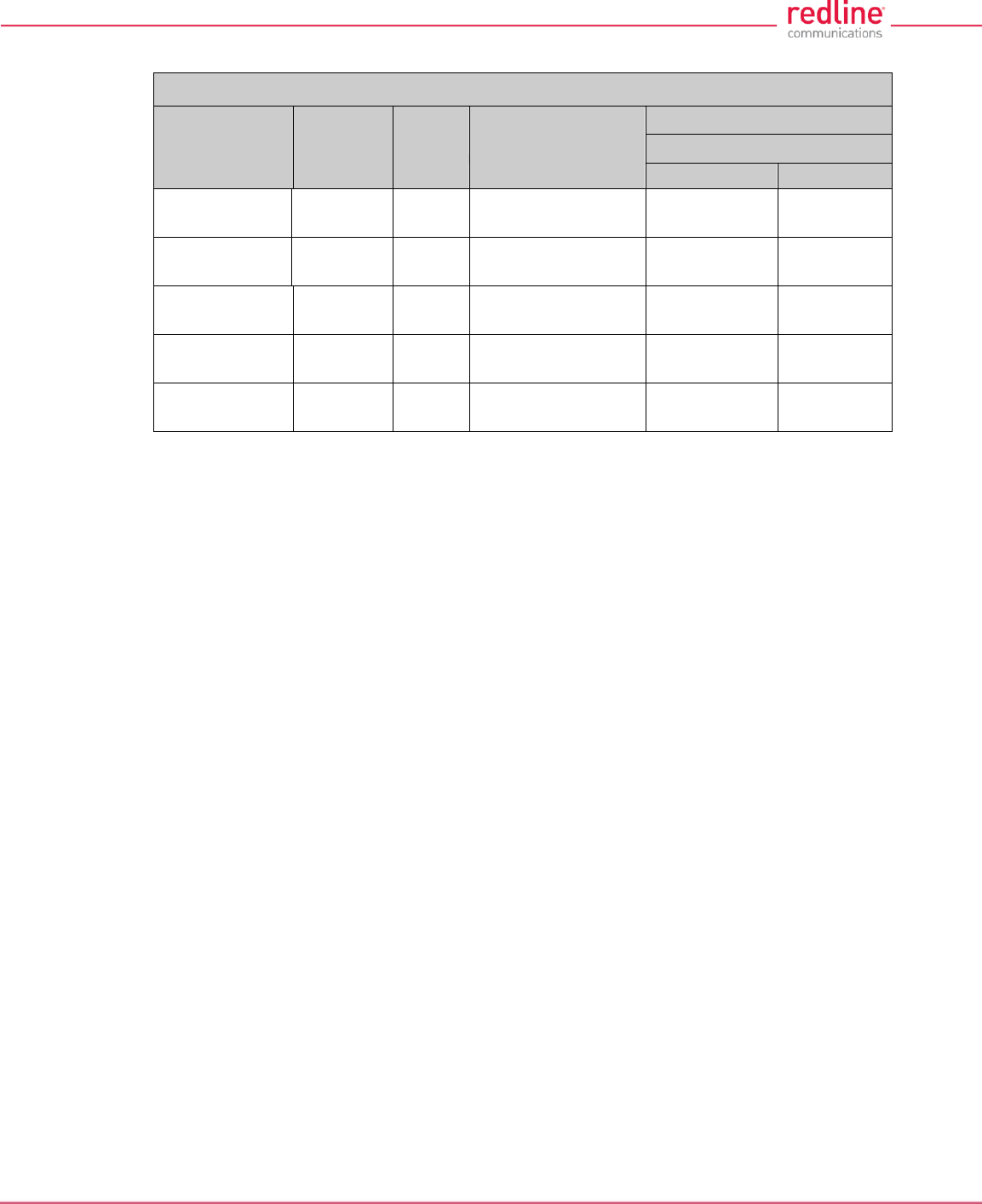
RDL-3000 User Manual
70-00158-01-DRAFT Proprietary Redline Communications © 2010 Page 141 of 142 November 25, 2010
Table 48: Spec. - FCC & IC Certified Antennas: 5.8 GHz PTP Band Edge Operation
Redline Order #
Application
Gain
(dBi)
Type
Max. Tx Power Setting (dBm)
5 MHz Channel Setting
5.730 GHz
5.845 GHz
A9014MTD
PTP
14
90°, 4.9-5.9 GHz,
Panel, Dual Pol.
18
18
A6015MTD
PTP
15
60°, 4.9-5.9 GHz,
Panel, Dual Pol.
18
18
A2308MFD
PTP
23
8°, 4.9-5.9 GHz,
Panel, Dual Pol.
18
18
A2FT2906LTPD
PTP
29
6°, 4.9-5.9 GHz,
Parabolic, Dual Pol.
18
18
A3FT3204LTPD
PTP
32
4°, 4.9-5.9 GHz,
Parabolic, Dual Pol.
16
16

70-00158-01-DRAFT Proprietary Redline Communications © 2010 Page 142 of 142 November 25, 2010
302 Town Centre Suite 100 Markham, Ontario Canada L3R 0E8
www.redlinecommunications.com