Redline Communications RDL3000A Advanced Broadband Wireless Infrastructure Solution User Manual 70 00158 01 DRAFT
Redline Communications Inc. Advanced Broadband Wireless Infrastructure Solution 70 00158 01 DRAFT
UserManual.wiki
>
Redline Communications
>
RDL3000A User Manual
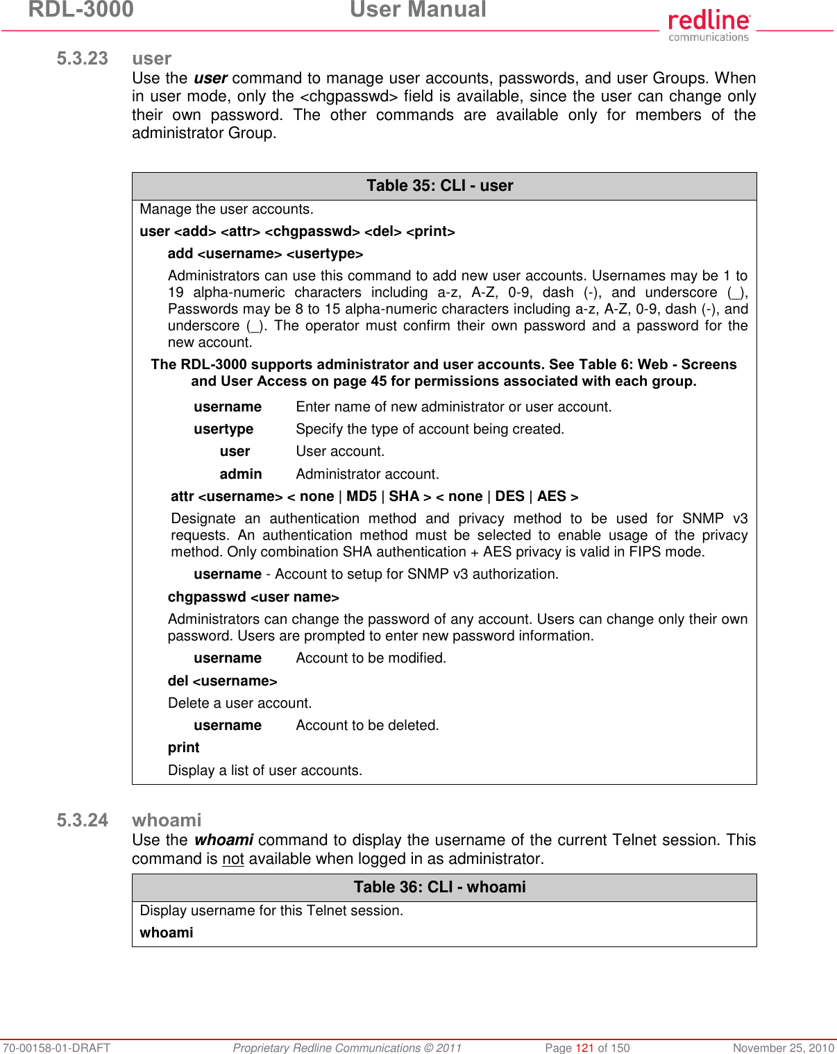
user manual
Navigation menu
Upload a User Manual
Namespaces
Wiki Guide
HTML
PDF
Info
Views
User Manual
Discussion / Help
Navigation
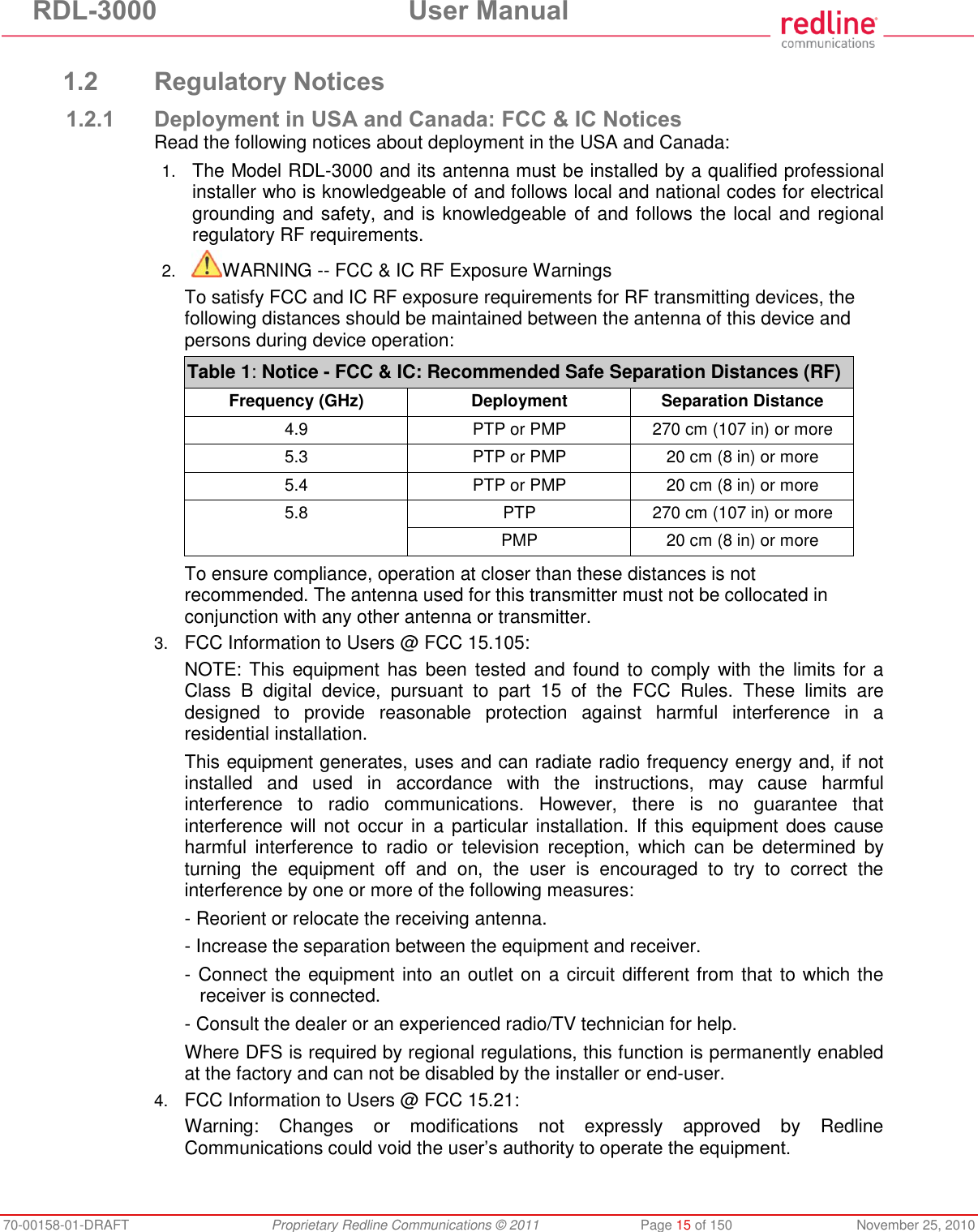
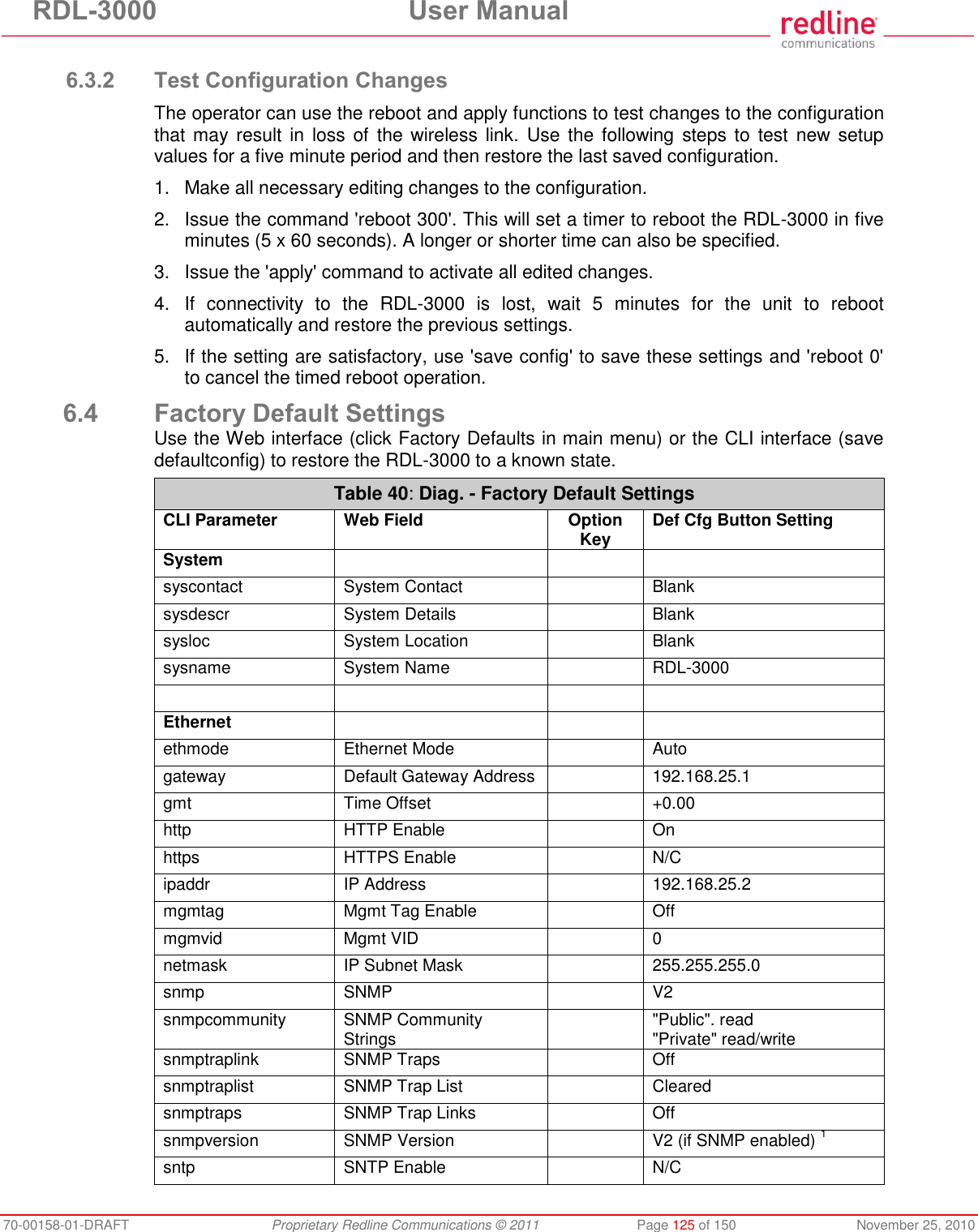
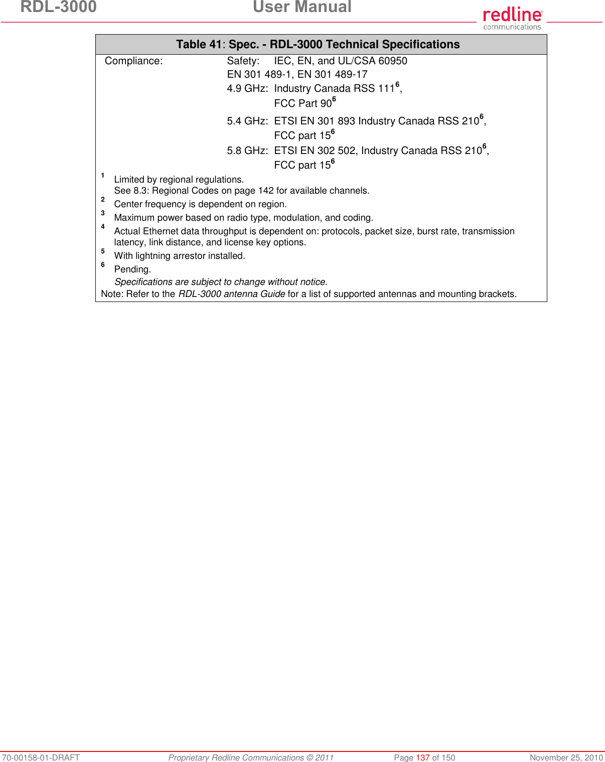
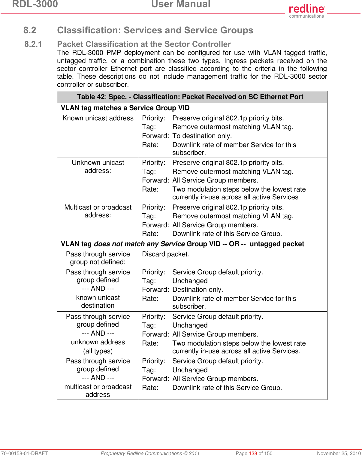
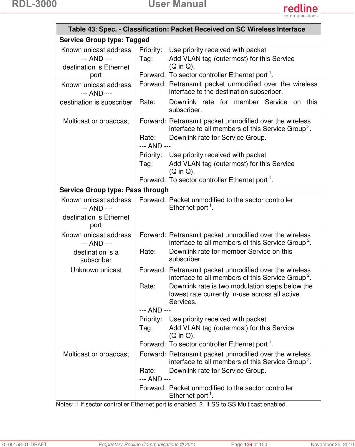
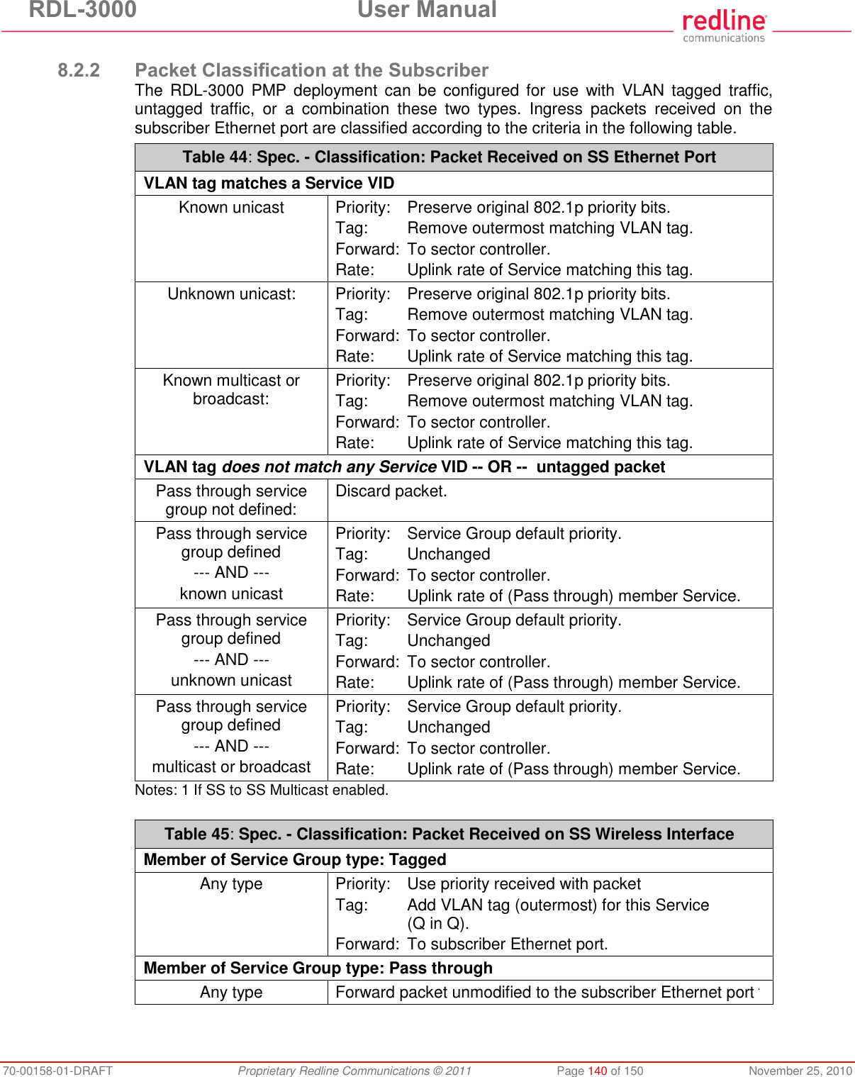
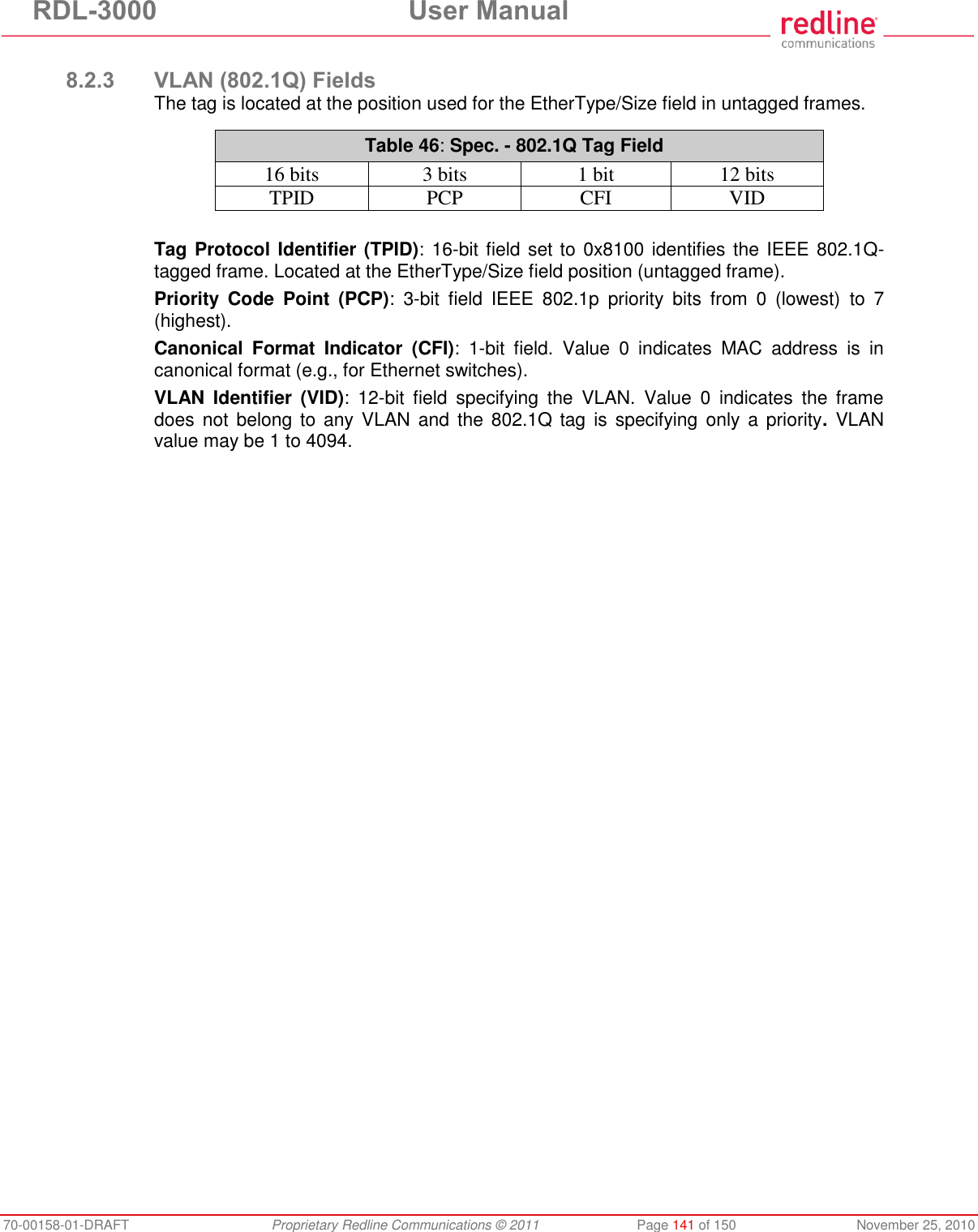
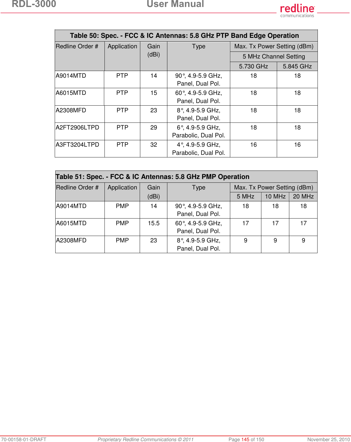
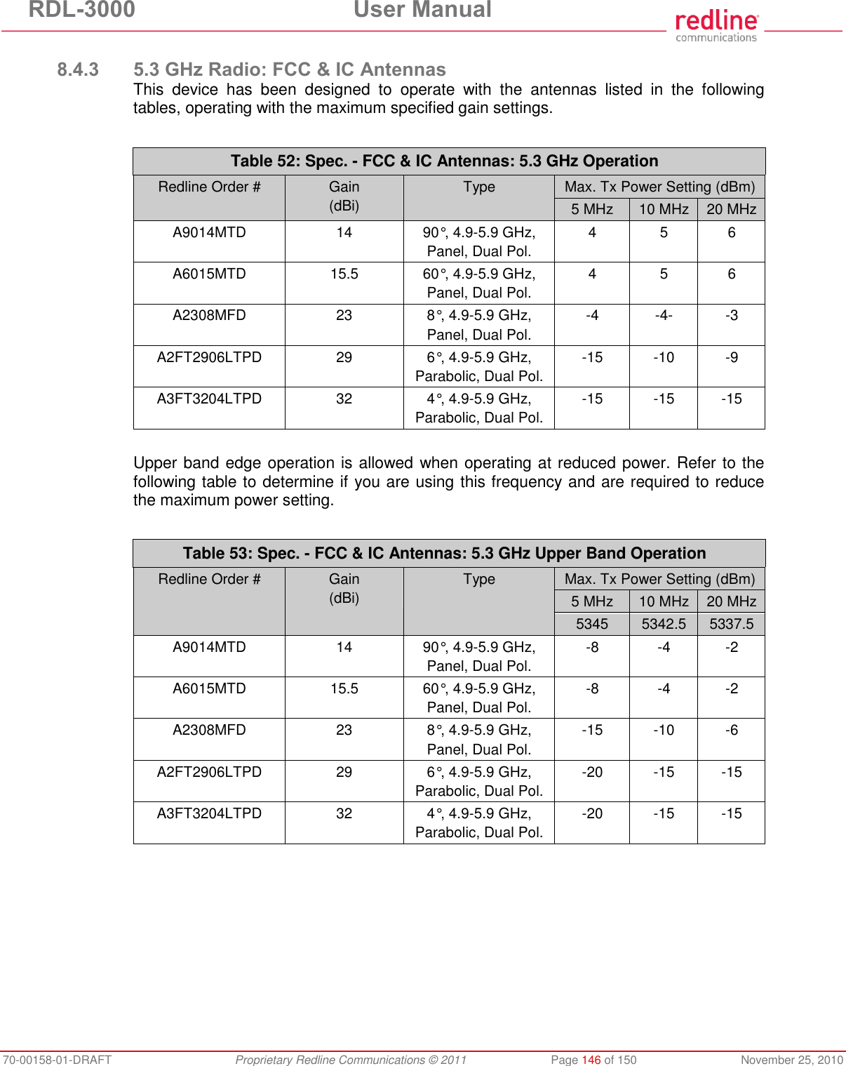
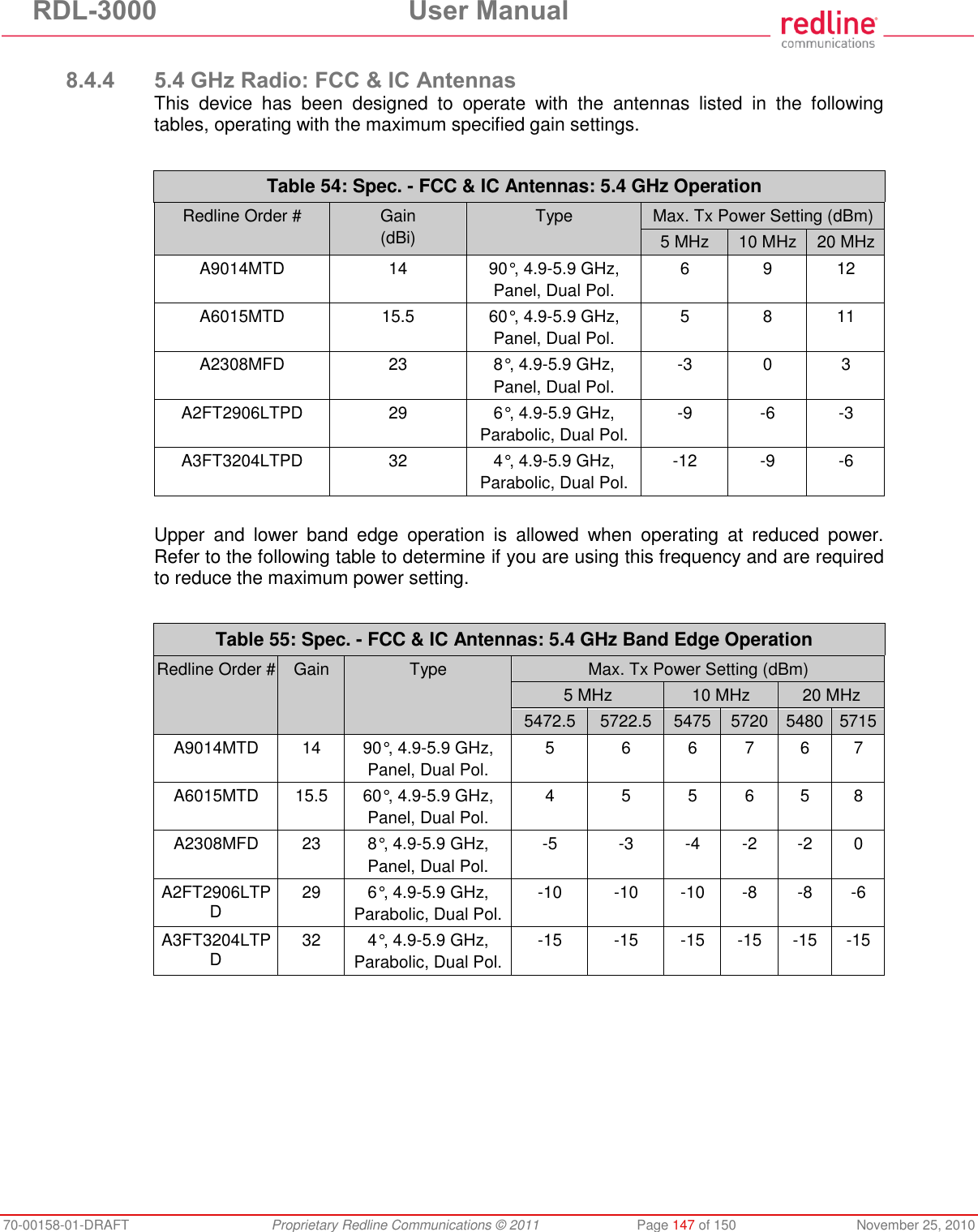
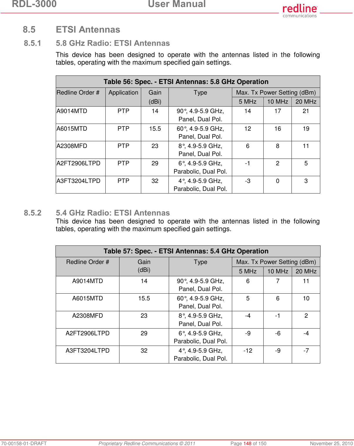
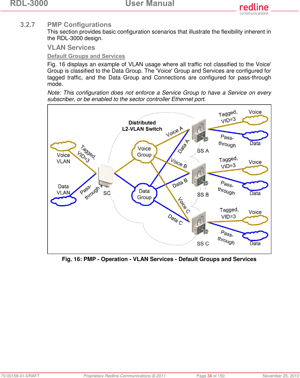
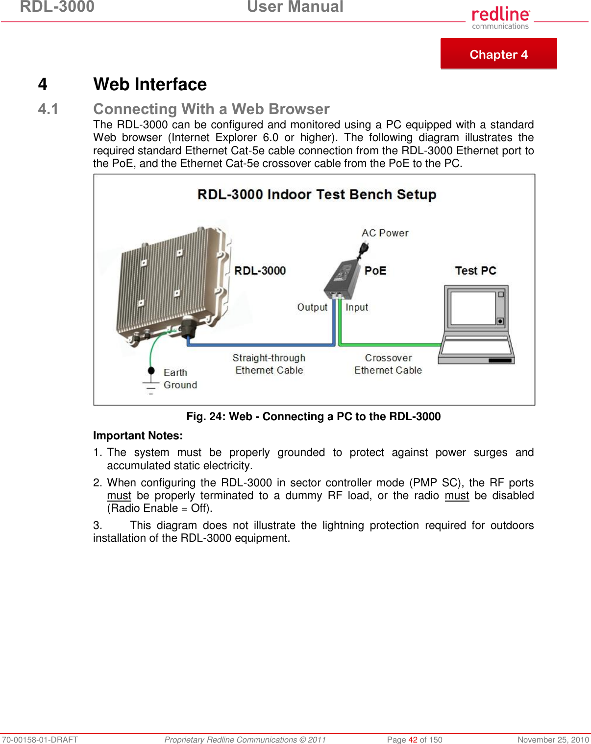
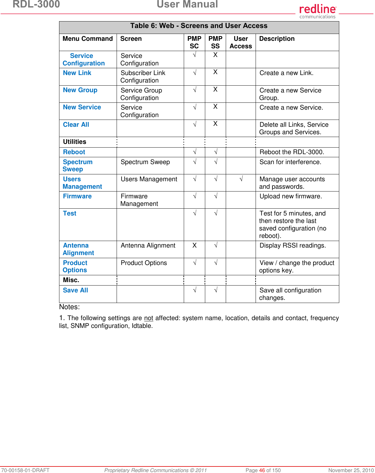
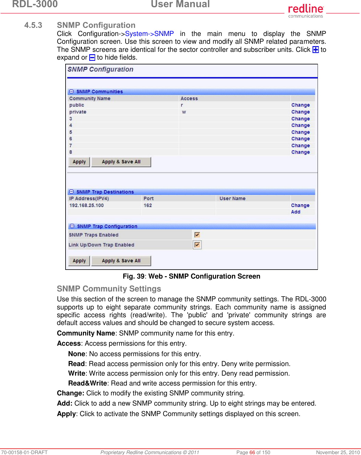
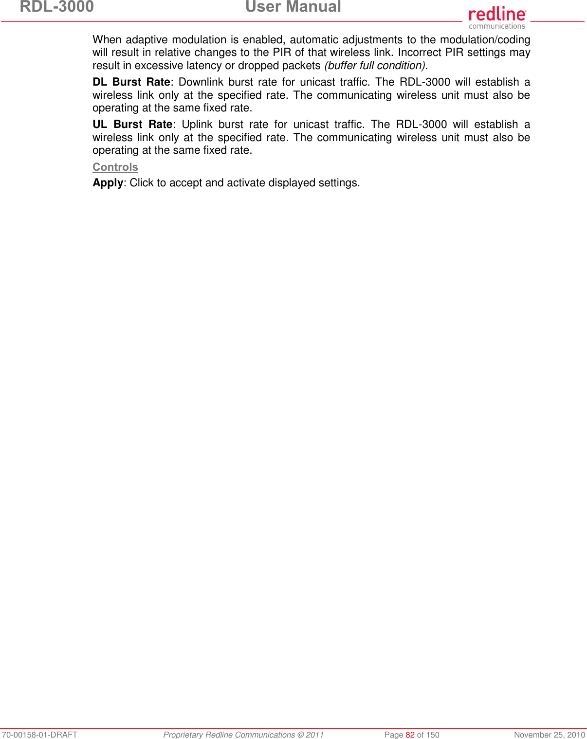
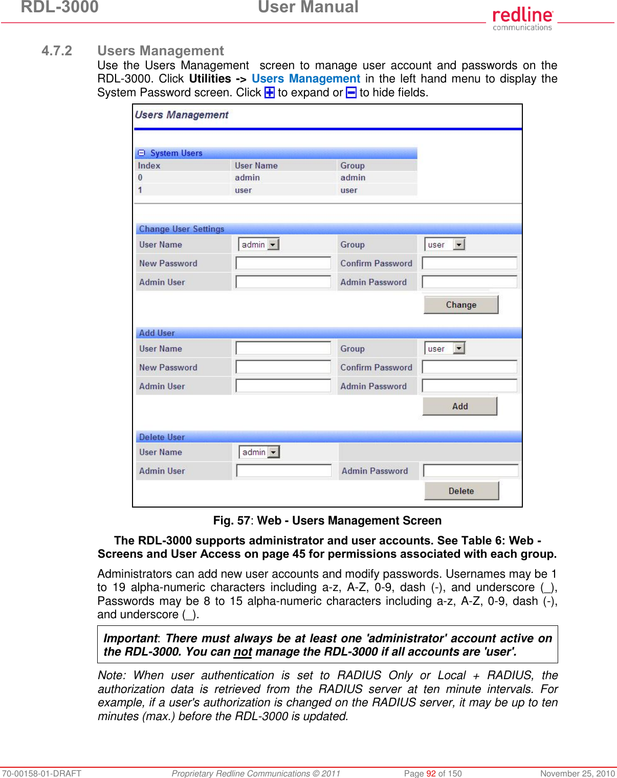
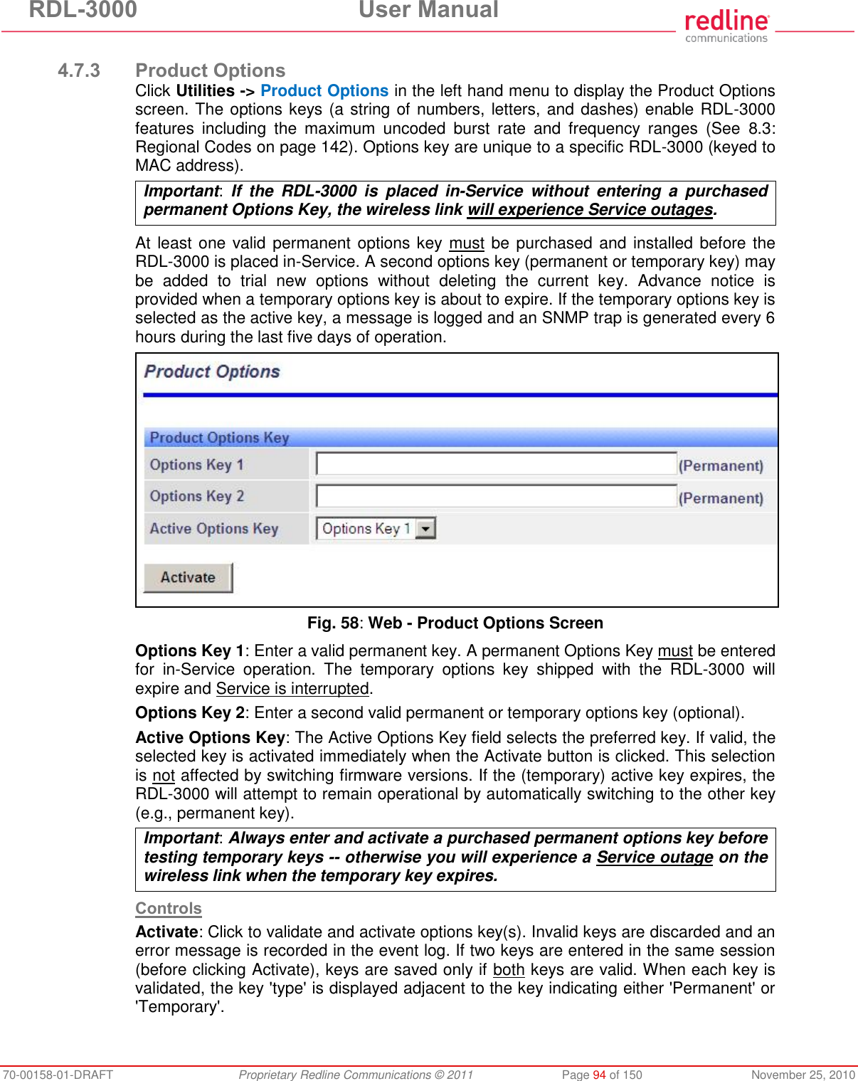
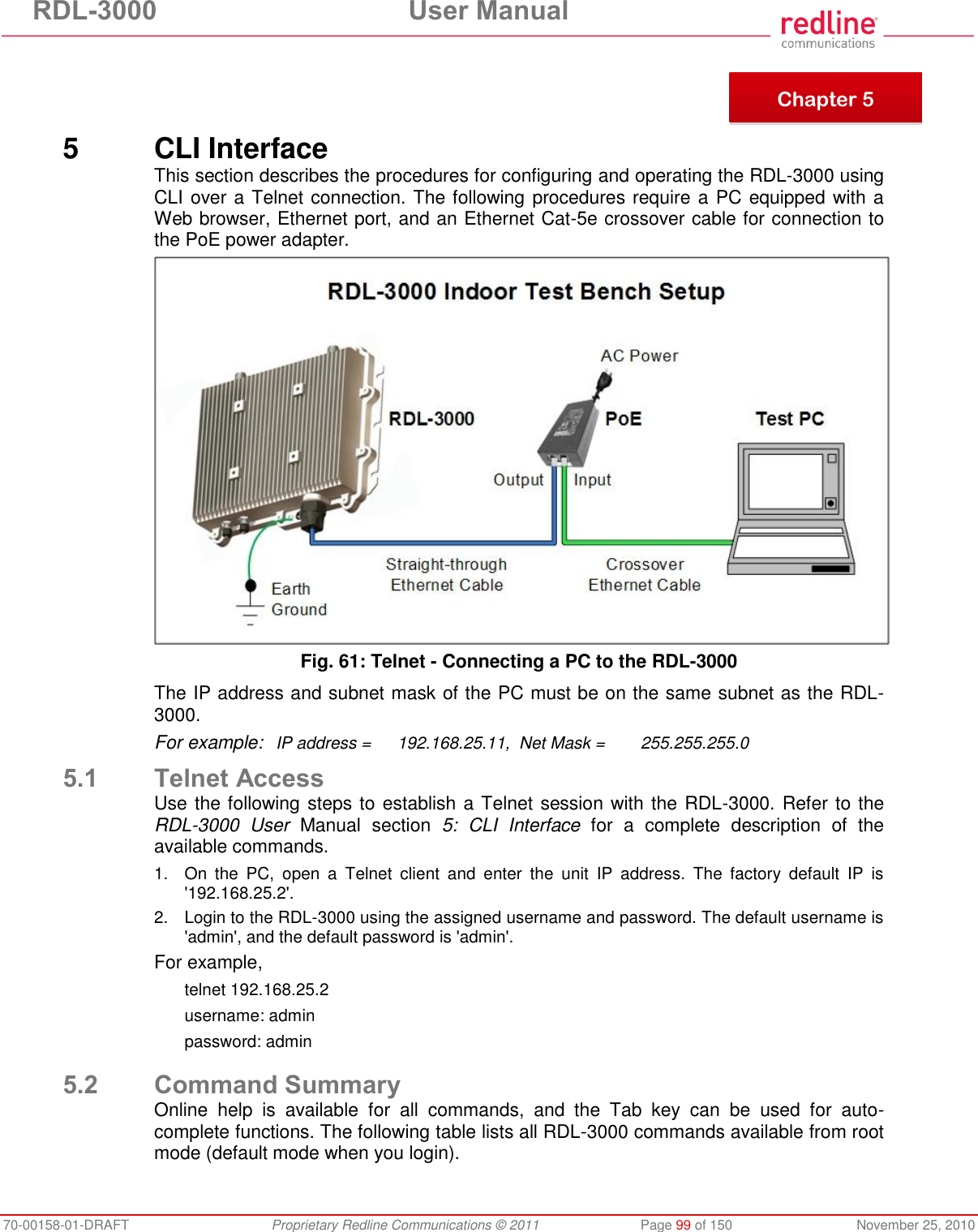
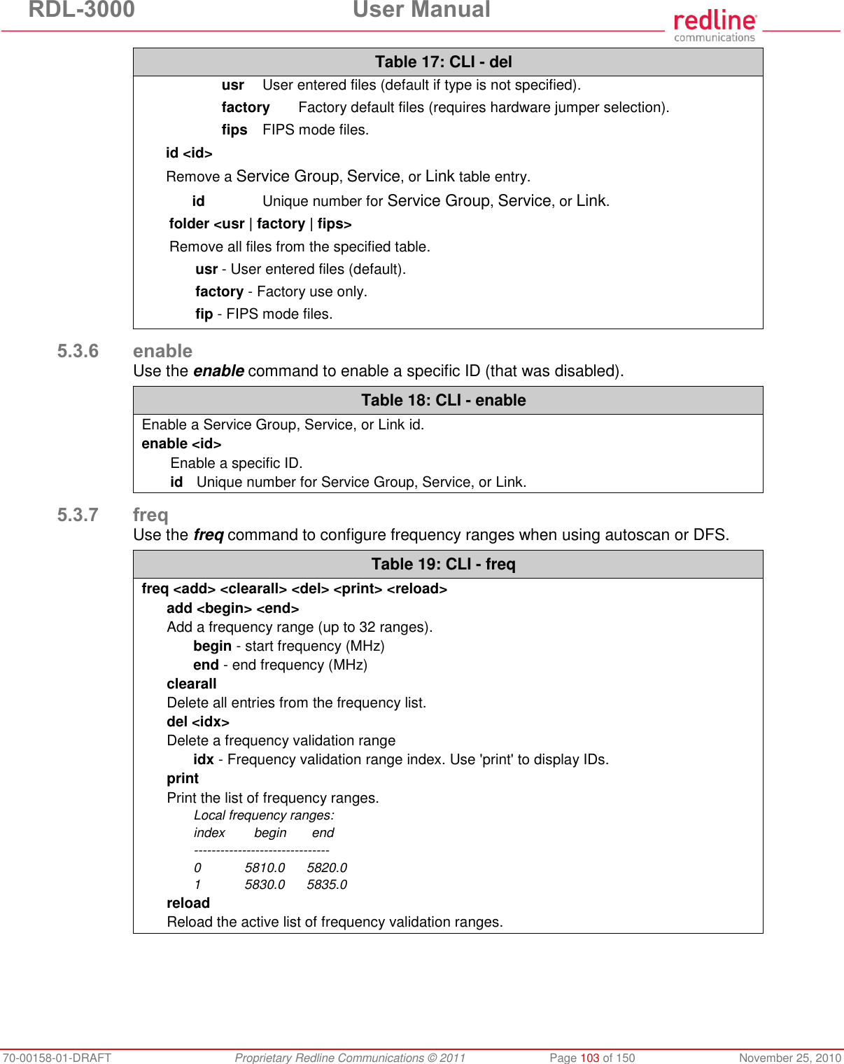
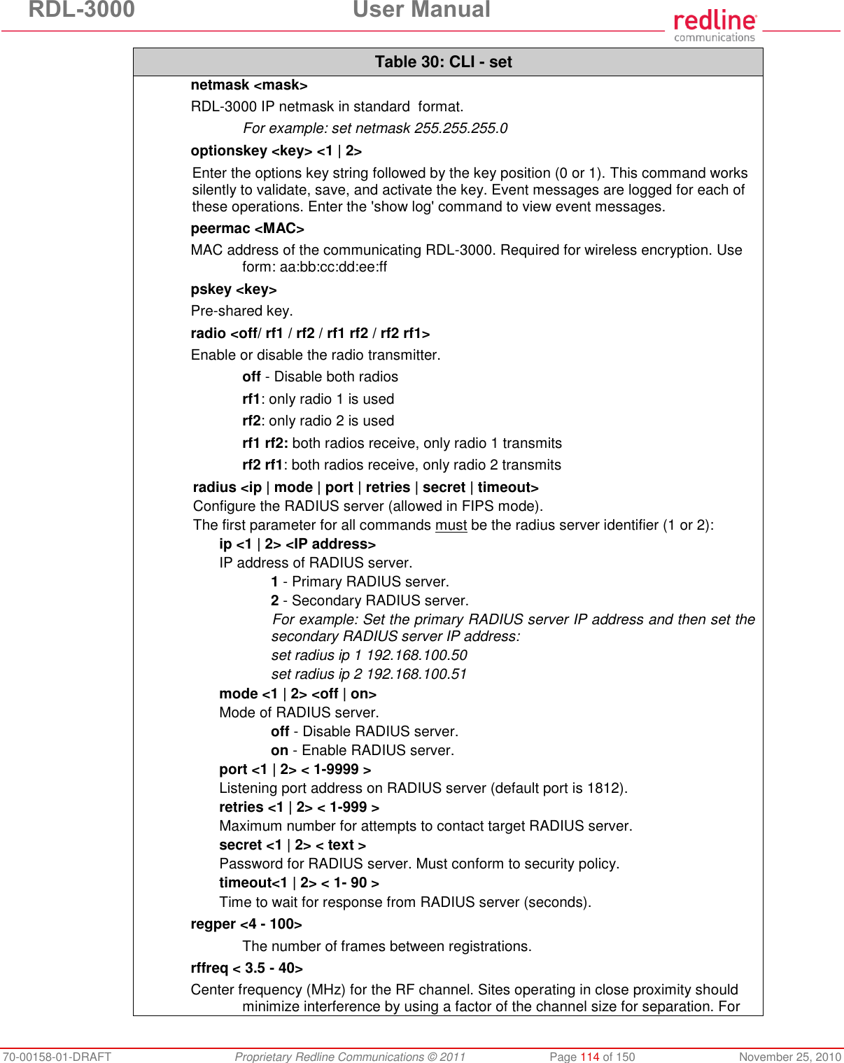
![RDL-3000 User Manual 70-00158-01-DRAFT Proprietary Redline Communications © 2011 Page 17 of 150 November 25, 2010 Instructions to UNII band Users Redline, in complete cooperation with the FCC, instructs professional installers and operators of this equipment in the UNII band to follow these guidelines. Review Table 3: Notice - FCC - TDWR System Locations to determine if the intended deployment location is near a TDWR site. 1. Operation in the TDWR band of 5600-5650 MHz is not permitted. The equipment does not allow the operator to use Web, CLI, or SNMP to set a frequency that overlaps this range. 2. Operation in the 5570-5680 MHz band (excluding 5600-5650 MHz) is permitted beyond 35 km (22 mi) AND not in line-of-sight of a TDWR site. 3. Operation in the 5570-5680 MHz band (excluding 5600-5650 MHz) within 35 km (22 mi) OR in line-of-sight of a TDWR site is allowed by observing a 30 MHz upper and lower guard band on the operational frequency of the nearby TWDR station. For example, if the nearby TDWR is Miami (5605 MHz), the base station frequency setting must exclude channels with center frequencies from 5575 MHz (30 MHz below 5605) to 5635 MHz (30 MHz above 5605). It is recommended that the operator register in the voluntary WISPA sponsored database. Go to the www.wispa.org website and click on TDWR to view more information and register in the online database. Frequency selection is regulated by a regional code integrated into each options key. This feature enforces compliance to regional regulatory statutes. Each options key is keyed to the unique MAC address of an RDL-3000 radio platform. Options keys can be generated only by Redline and its authorized agents. End-users can not generate or modify options keys (to obtain or alter regional codes). Redline provides technical training programs and information covering network design and installation for Redline distributors, value added resellers, installers, and other partners. This program is intended in part to train participants to a level of understanding where they are competent to order, setup and configure the Redline wireless equipment to be in compliance with regulatory requirements in the region where this equipment is installed. Redline sales order processing is also trained to verify that regional codes are consistent with the intended deployment location as documented in the sales order. Table 3: Notice - FCC - TDWR System Locations STATE CITY LONG. [degrees] LAT. [degrees] FREQ. [MHz] ELEV. [ft] ANTENNA HEIGHT [ft] AZ PHOENIX W 112 09 46 N 33 25 14 5610 1024 64 CO DENVER W 104 31 35 N 39 43 39 5615 5643 64 FL FT LAUDERDALE W 080 20 39 N 26 08 36 5645 7 113 FL MIAMI W 080 29 28 N 25 45 27 5605 10 113 FL ORLANDO W 081 19 33 N 28 20 37 5640 72 97 FL TAMPA W 082 31 04 N 27 51 35 5620 14 80 FL WEST PALM BEACH W 080 16 23 N 26 41 17 5615 20 113 GA ATLANTA W 084 15 44 N 33 38 48 5615 962 113 IL MCCOOK W 087 51 31 N 41 47 50 5615 646 97 IL CRESTWOOD W 087 43 47 N 41 39 05 5645 663 113 IN INDIANAPOLIS W 086 26 08 N 39 38 14 5605 751 97 KS WICHITA W 097 26 13 N 37 30 26 5603 1270 80 KY COVINGTON CINCINNATI W 084 34 48 N 38 53 53 5610 942 97](https://usermanual.wiki/Redline-Communications/RDL3000A/User-Guide-1577952-Page-17.png)
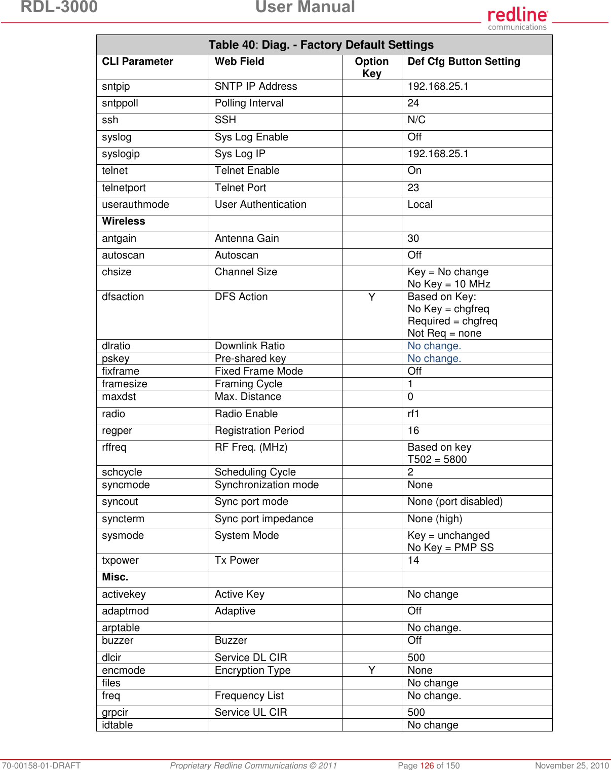
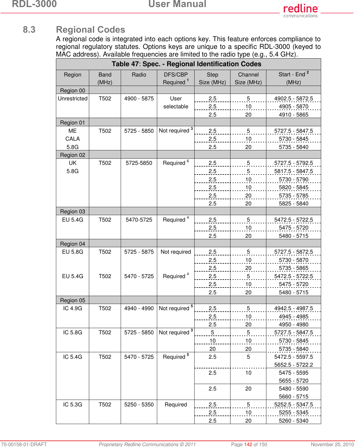
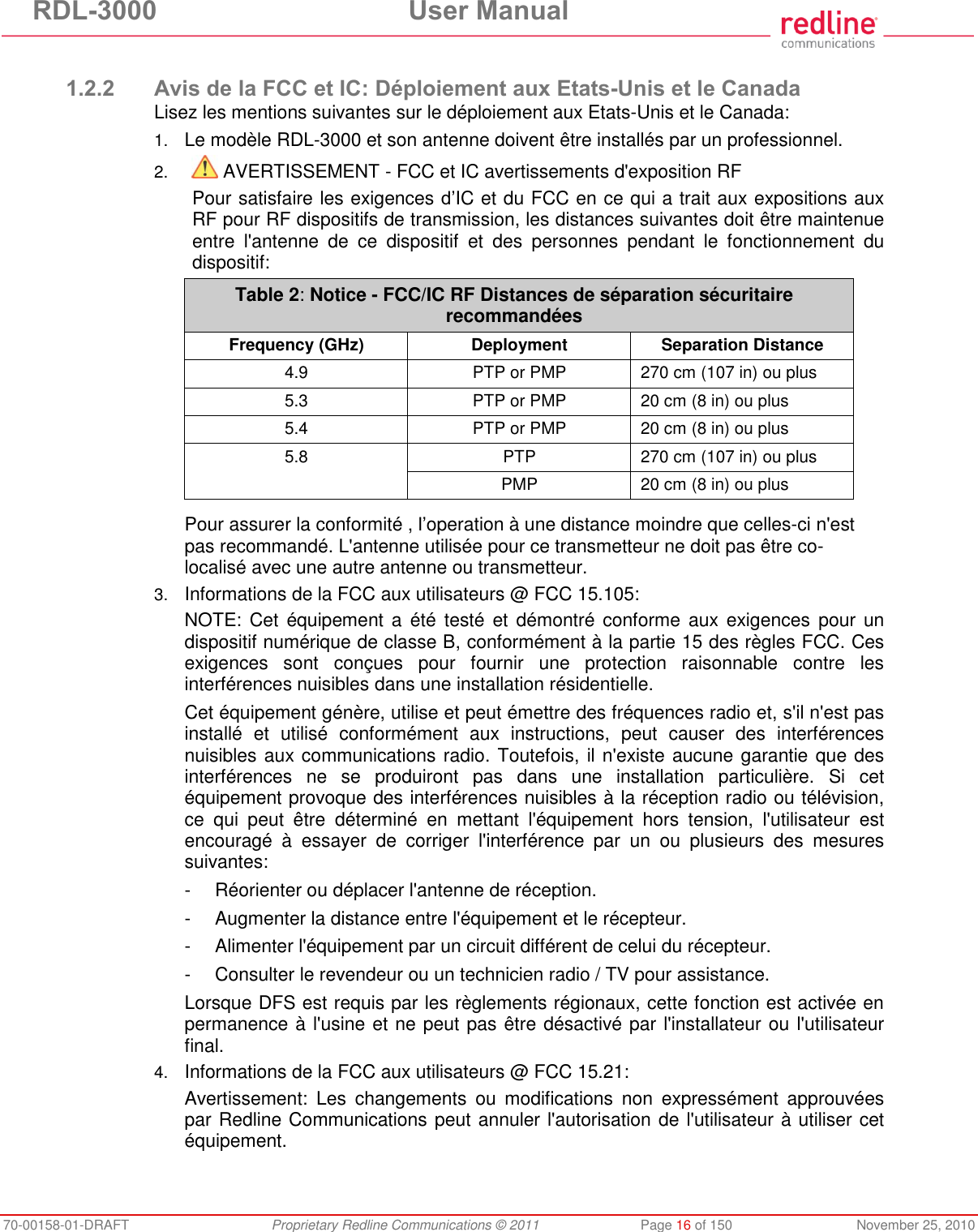
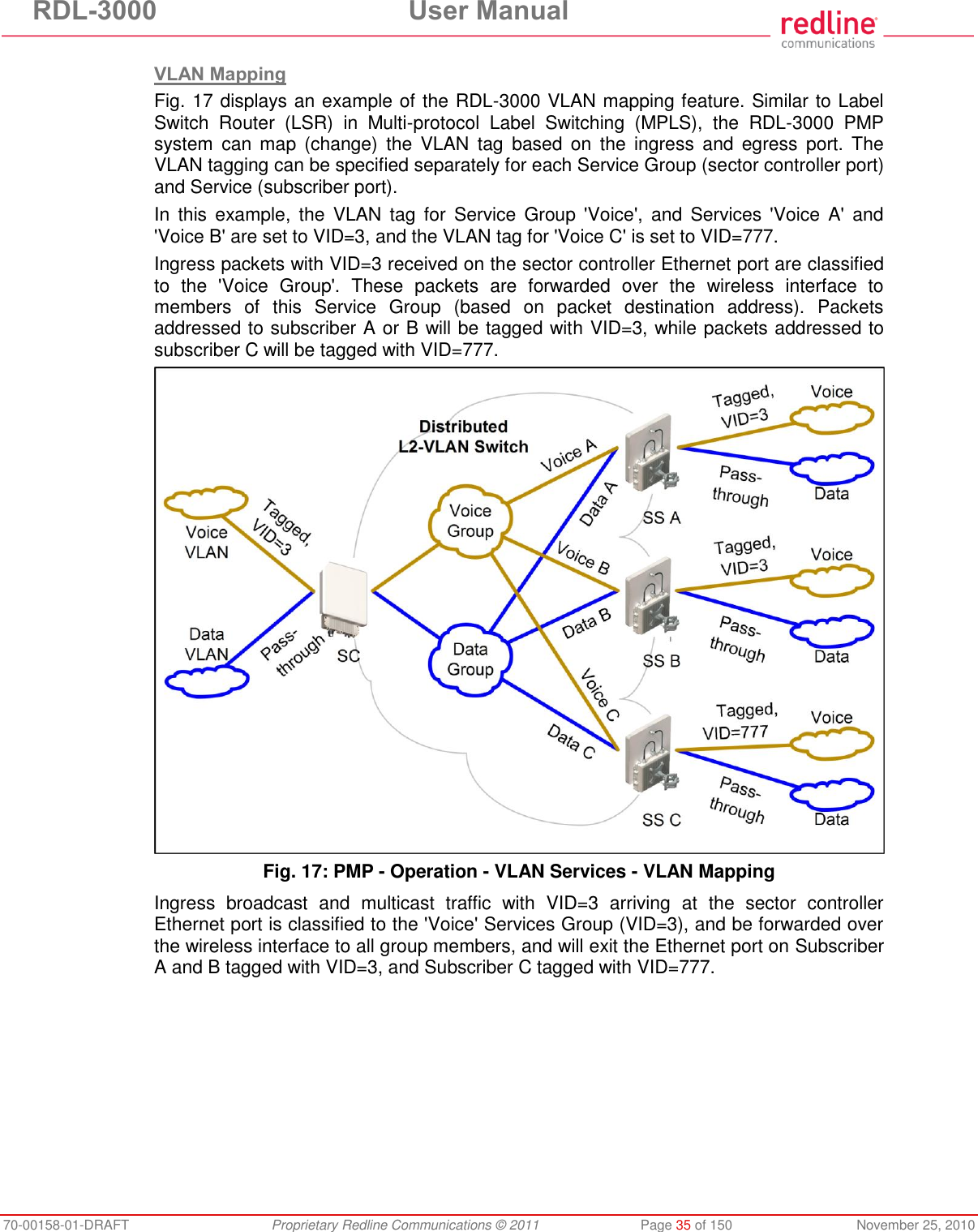
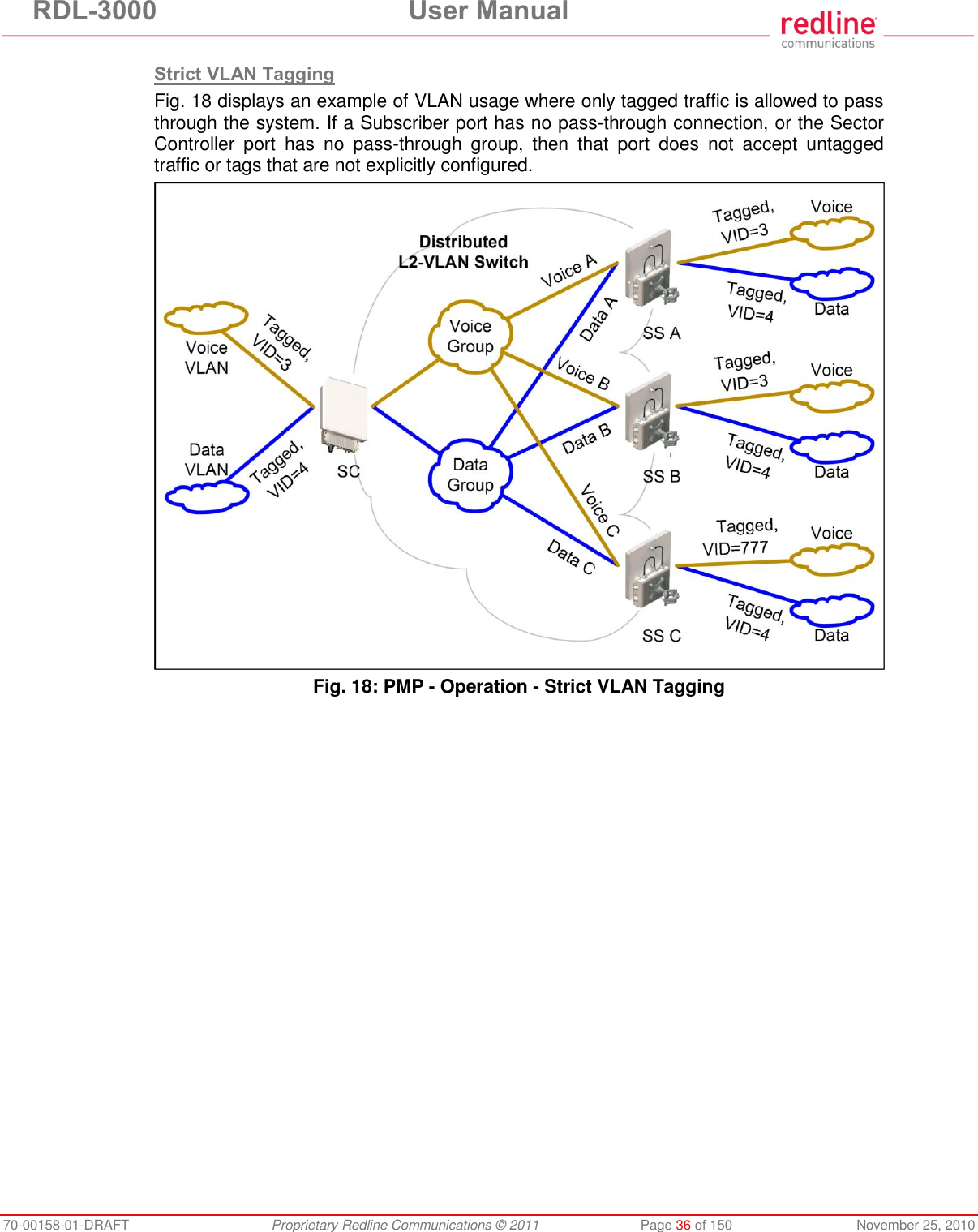
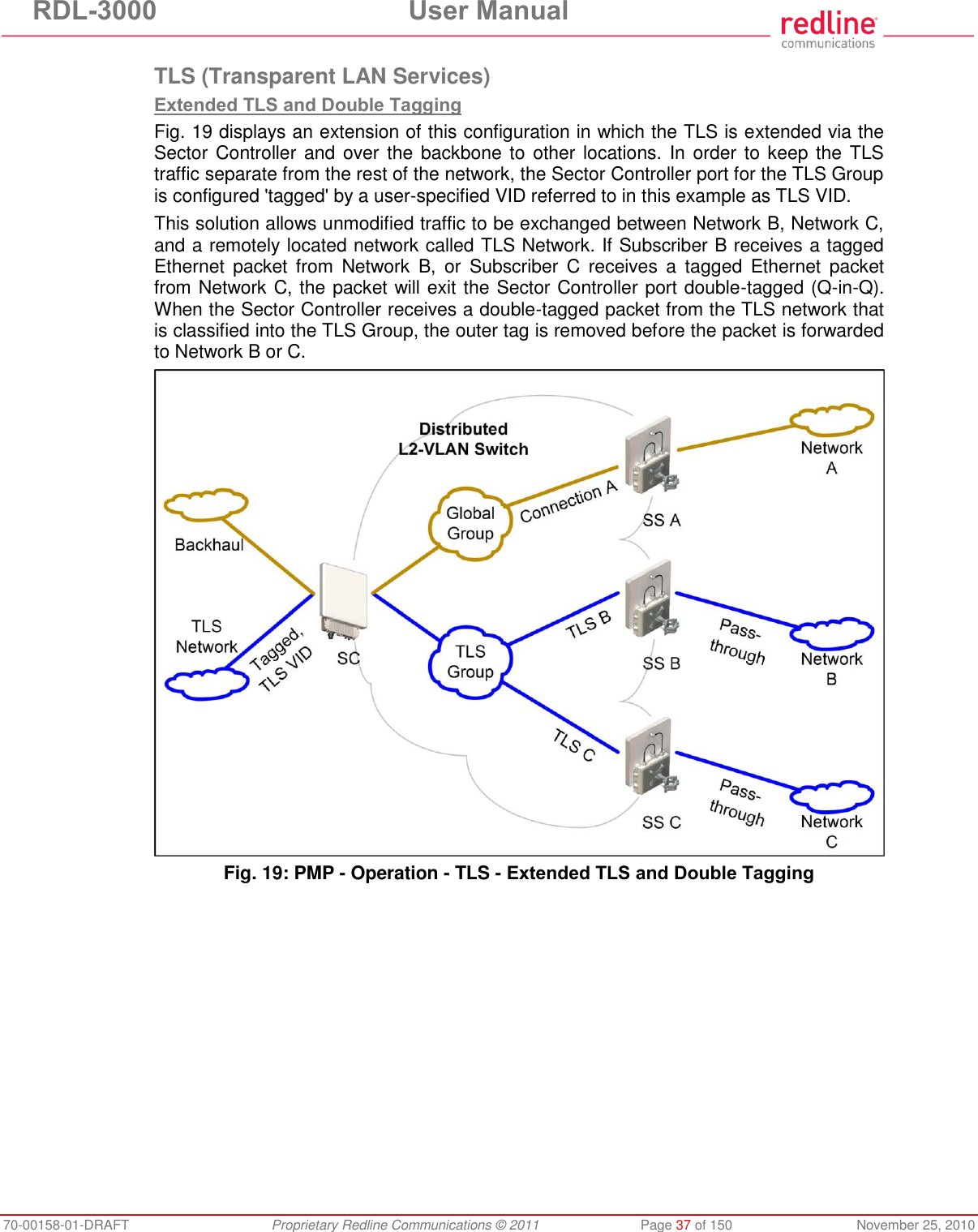
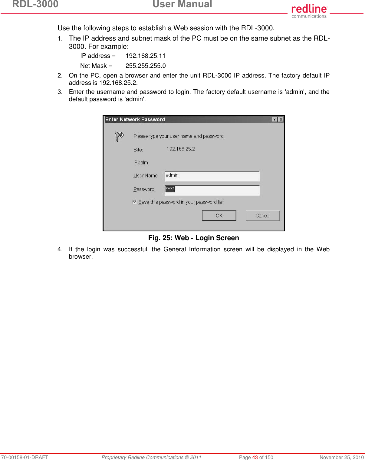
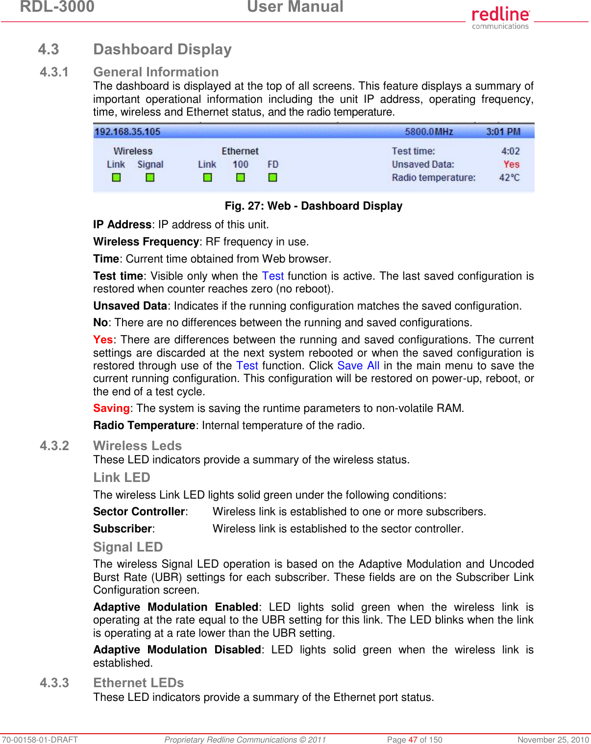
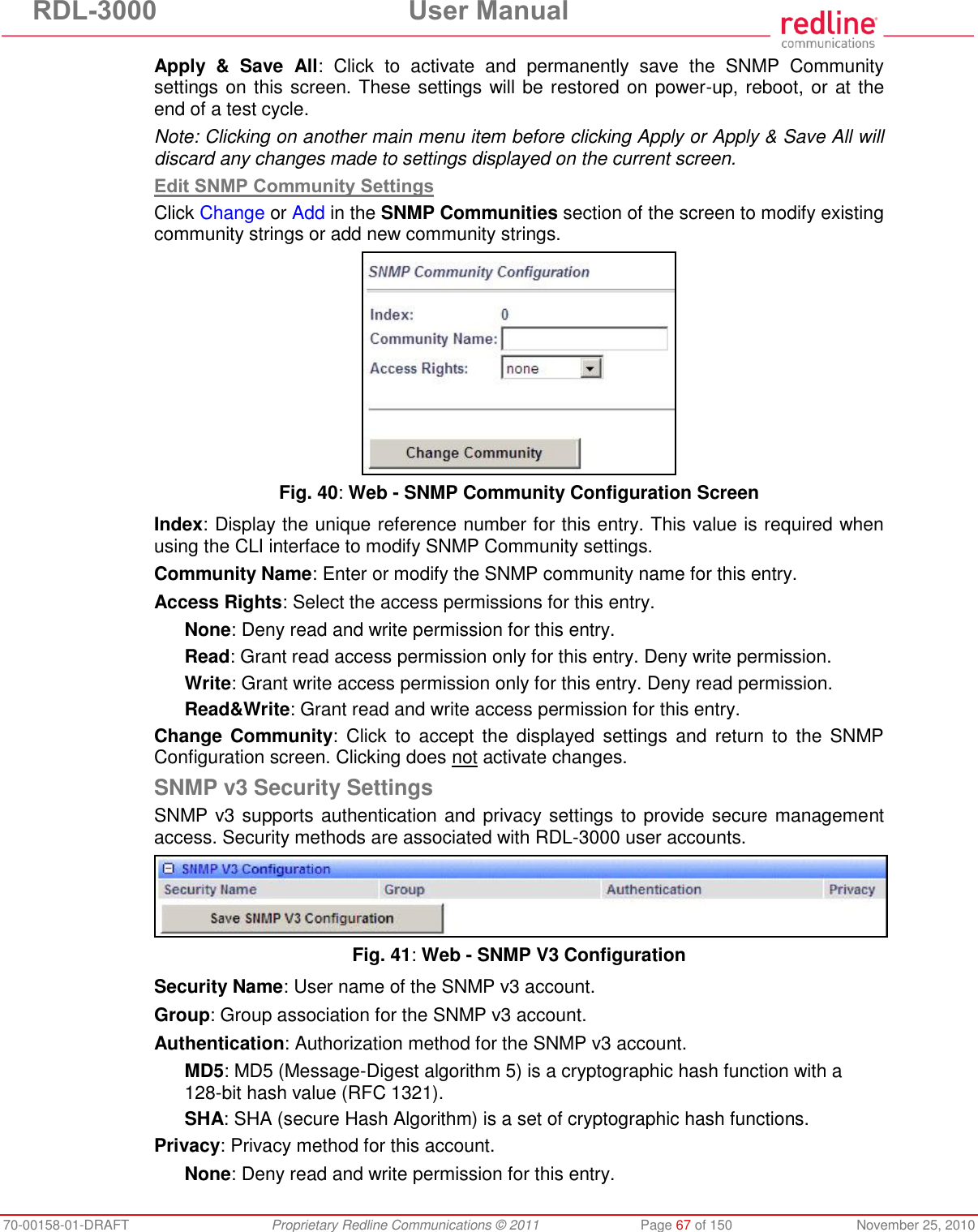
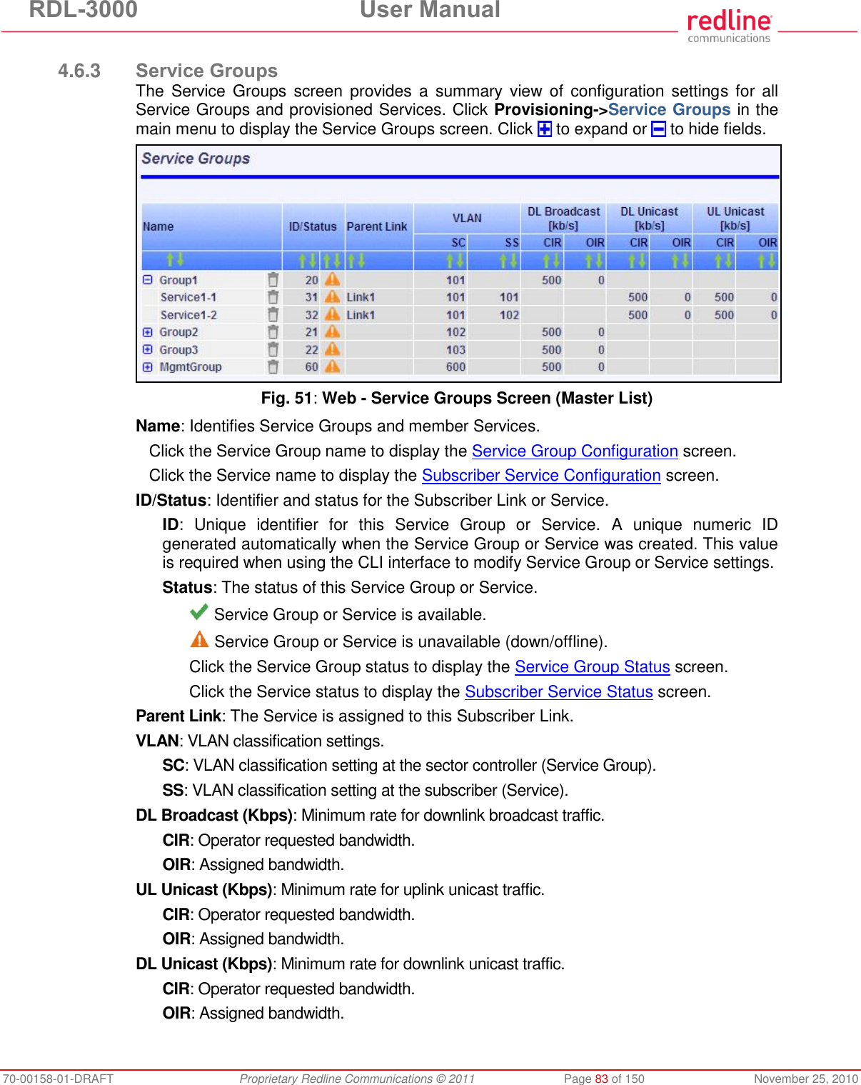
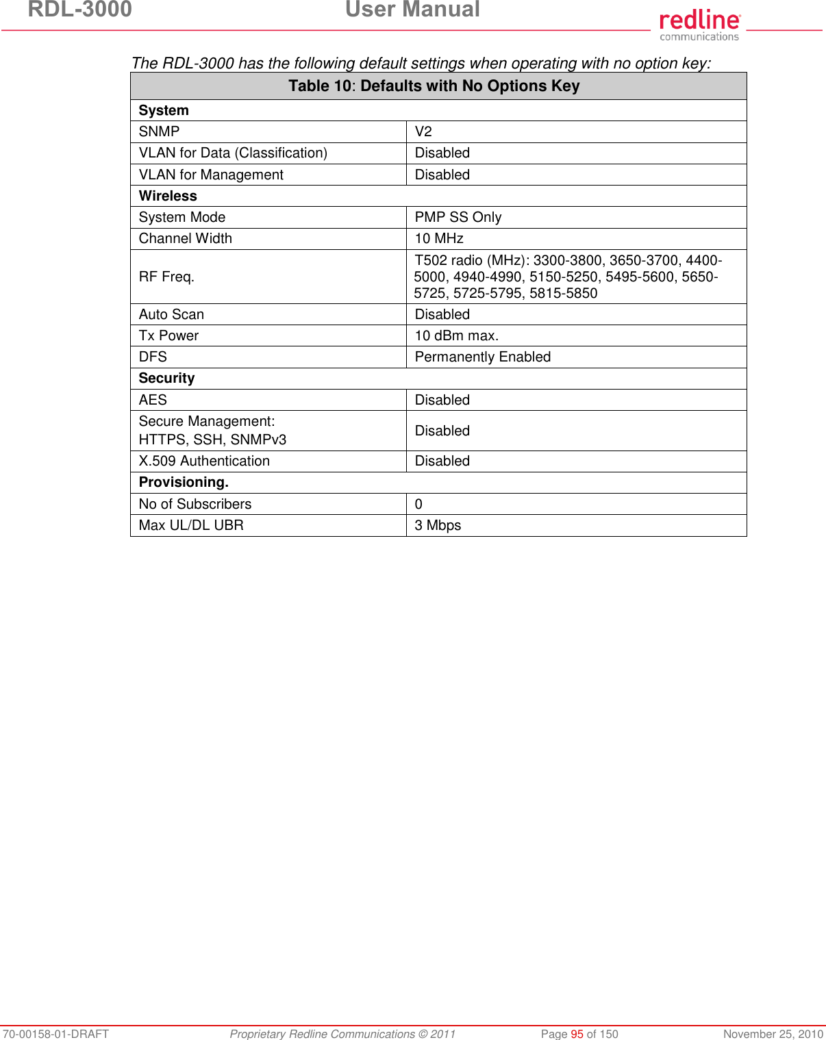
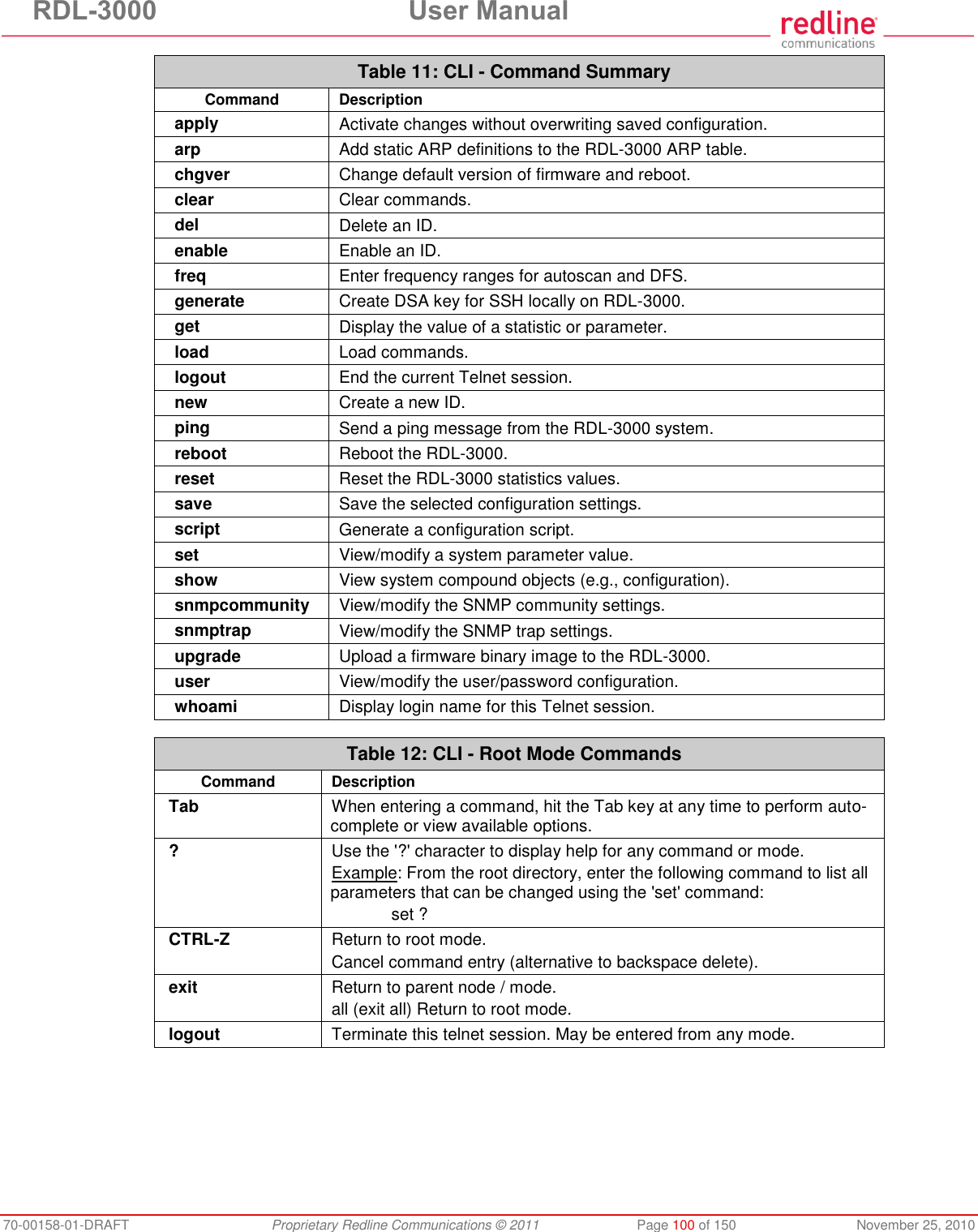
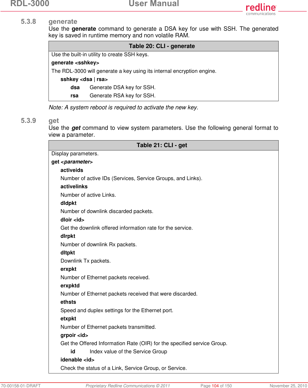
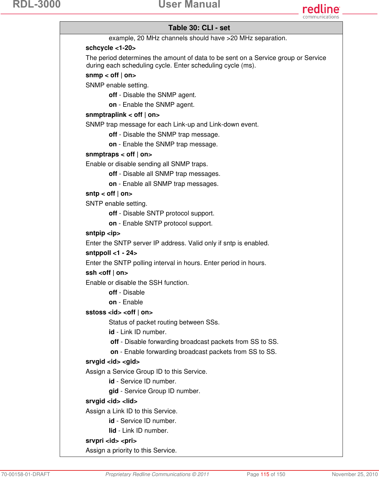
![RDL-3000 User Manual 70-00158-01-DRAFT Proprietary Redline Communications © 2011 Page 18 of 150 November 25, 2010 Table 3: Notice - FCC - TDWR System Locations STATE CITY LONG. [degrees] LAT. [degrees] FREQ. [MHz] ELEV. [ft] ANTENNA HEIGHT [ft] KY LOUISVILLE W 085 36 38 N 38 02 45 5646 617 113 LA NEW ORLEANS W 090 24 11 N 30 01 18 5645 2 97 MA BOSTON W 070 56 01 N 42 09 30 5610 151 113 MD BRANDYWINE W 076 50 42 N 38 41 43 5635 233 113 MD BENFIELD W 076 37 48 N 39 05 23 5645 184 113 MD CLINTON W 076 57 43 N 38 45 32 5615 249 97 MI DETROIT W 083 30 54 N 42 06 40 5615 656 113 MN MINNEAPOLIS W 092 55 58 N 44 52 17 5610 1040 80 MO KANSAS CITY W 094 44 31 N 39 29 55 5605 1040 64 MO SAINT LOUIS W 090 29 21 N 38 48 20 5610 551 97 MS DESOTO COUNTY W 089 59 33 N 34 53 45 5610 371 113 NC CHARLOTTE W 080 53 06 N 35 21 39 5608 807 113 NC RALEIGH DURHAM W 078 41 50 N 36 00 07 5647 400 113 NJ WOODBRIDGE W 074 16 13 N 40 35 37 5620 19 113 NJ PENNSAUKEN W 075 04 12 N 39 56 57 5610 39 113 NV LAS VEGAS W 115 00 26 N 36 08 37 5645 1995 64 NY FLOYD BENNETT FIELD W 073 52 49 N 40 35 20 5647 8 97 OH DAYTON W 084 07 23 N 40 01 19 5640 922 97 OH CLEVELAND W 082 00 28 N 41 17 23 5645 817 113 OH COLUMBUS W 082 42 55 N 40 00 20 5605 1037 113 OK AERO. CTR TDWR #1 W 097 37 31 N 35 24 19 5610 1285 80 OK AERO. CTR TDWR #2 W 097 37 43 N 35 23 34 5620 1293 97 OK TULSA W 095 49 34 N 36 04 14 5605 712 113 OK OKLAHOMA CITY W 097 30 36 N 35 16 34 5603 1195 64 PA HANOVER W 080 29 10 N 40 30 05 5615 1266 113 PR SAN JUAN W 066 10 46 N 18 28 26 5610 59 113 TN NASHVILLE W 086 39 42 N 35 58 47 5605 722 97 TX HOUSTON INTERCONTL W 095 34 01 N 30 03 54 5605 154 97 TX PEARLAND W 095 14 30 N 29 30 59 5645 36 80 Service & Warranty Information 1. Refer all repairs to qualified Service personnel. Do not remove the covers or modify any part of this device, as this action will void the warranty. 2. Locate the serial numbers and record these for future reference. Use the space below to affix serial number stickers. Also, record the MAC address identified on the unit product label. 3. Redline does not endorse or support the use of outdoor cable assemblies: i) not supplied by Redline, ii) third-party products that do not meet Redline's cable and connector assembly specifications, or iii) cables not installed and weatherproofed as specified in the RDL-3000 Installation Guidelines manual. Refer to the Redline Limited Standard Warranty and RedCare Service agreements.](https://usermanual.wiki/Redline-Communications/RDL3000A/User-Guide-1577952-Page-18.png)
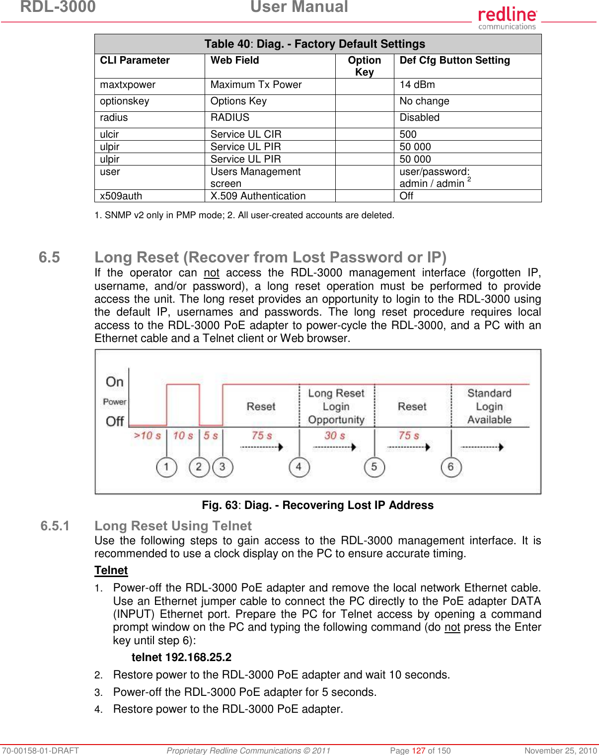
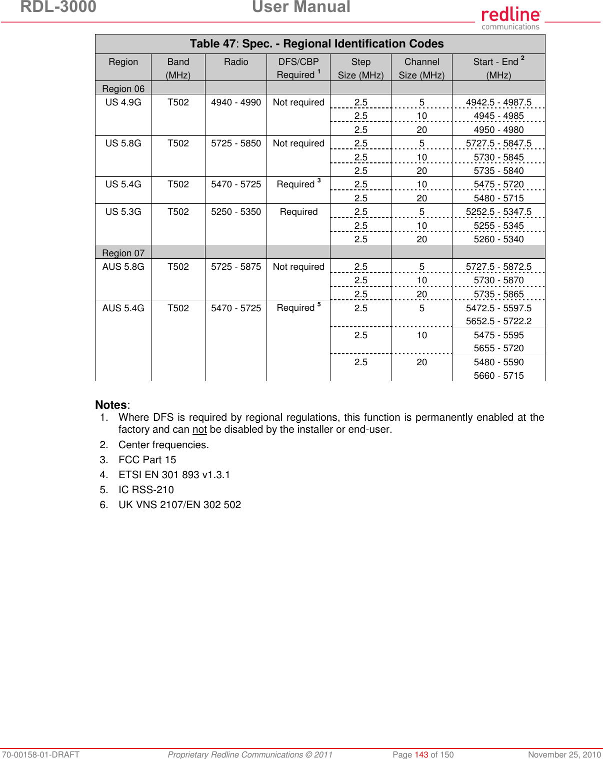
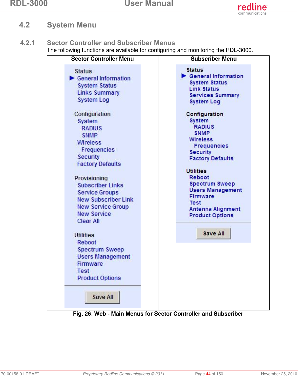
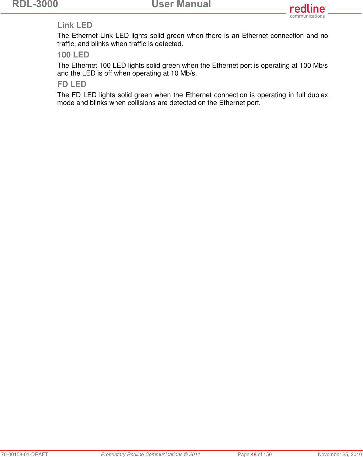
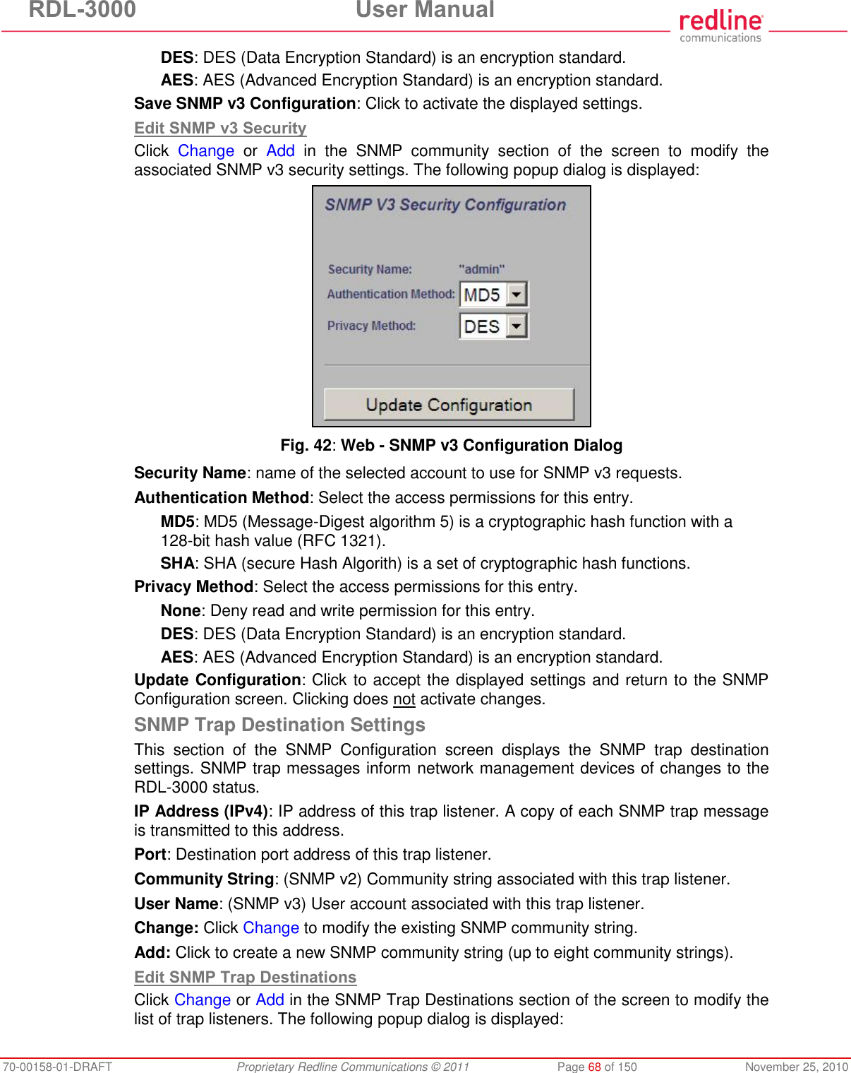
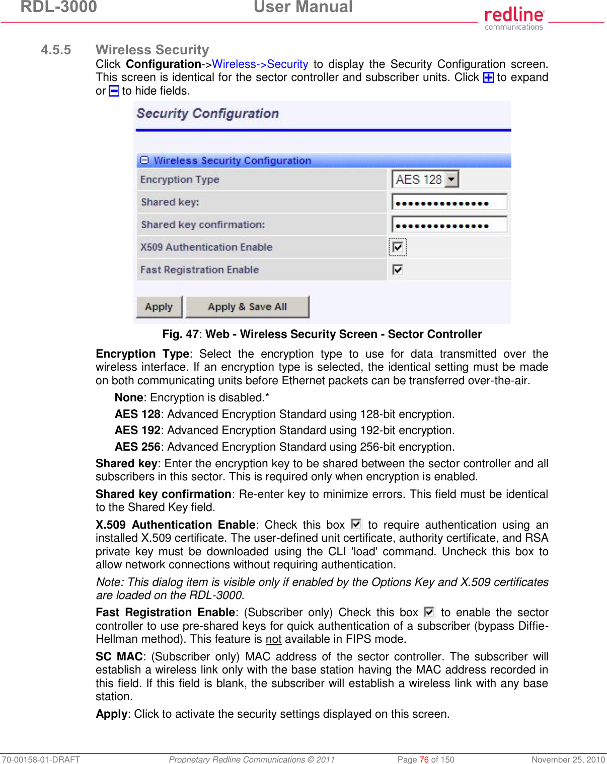
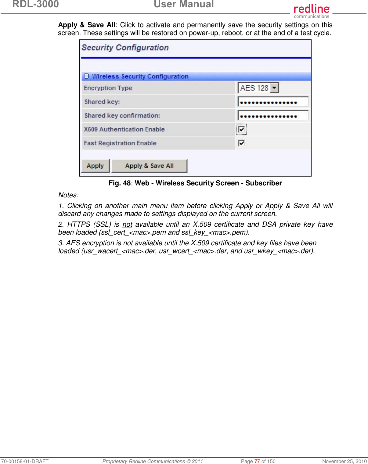
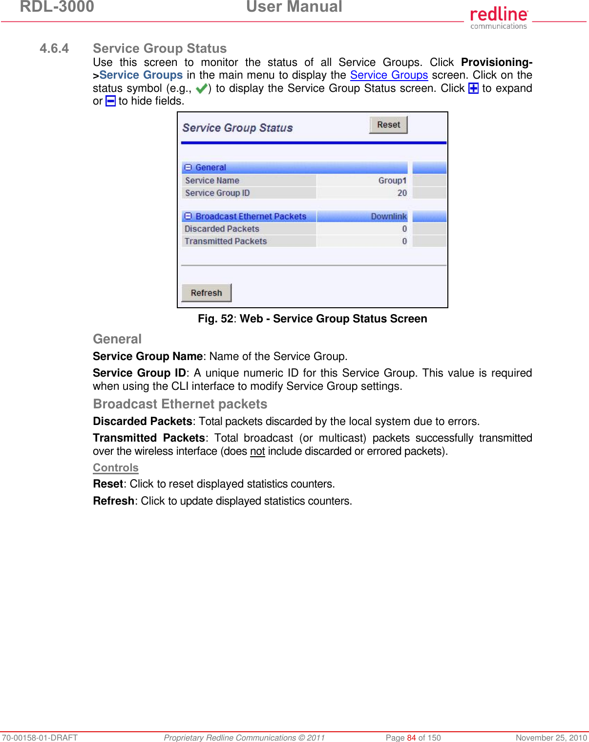
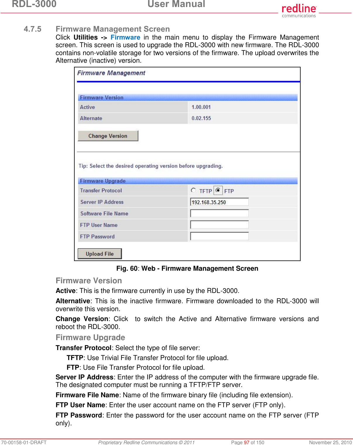
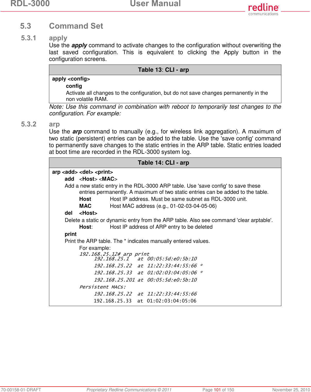
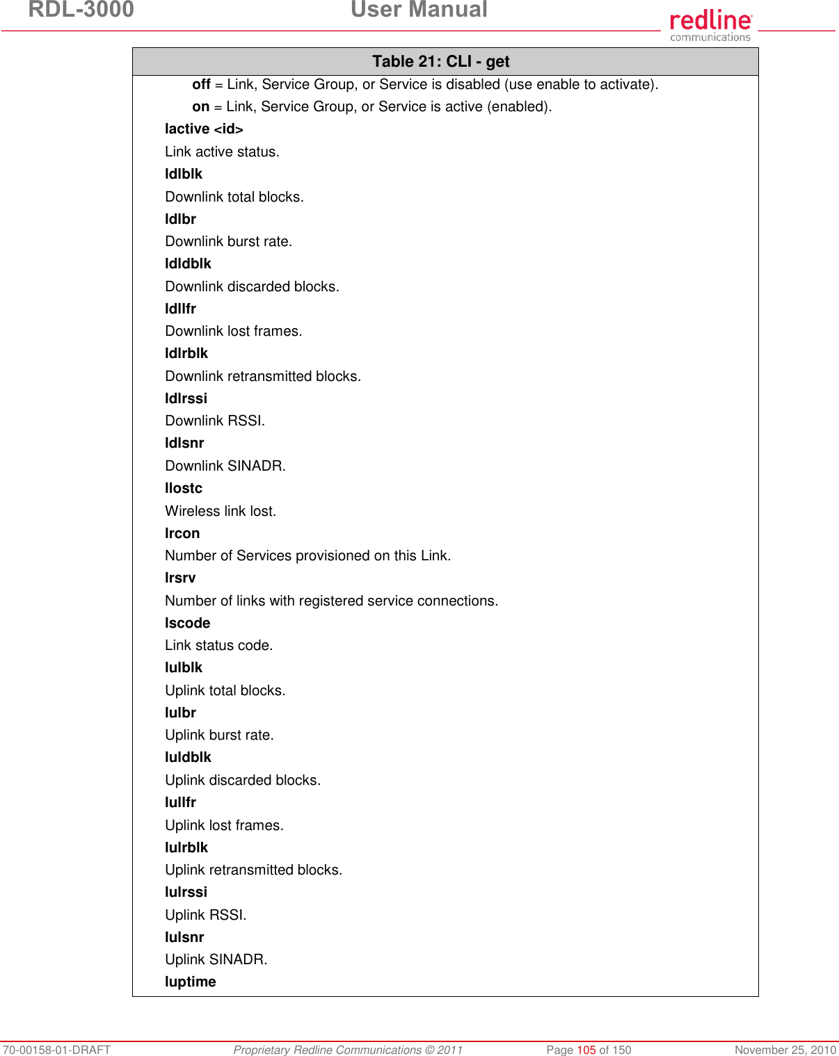
![RDL-3000 User Manual 70-00158-01-DRAFT Proprietary Redline Communications © 2011 Page 23 of 150 November 25, 2010 2.8 Management Interfaces The operator can use a standard web browser to access all settings and statistics necessary to configure and monitor the operation of the RDL-3000. All functions are also supported using the Command Line Interface (CLI) using Telnet (see page 99). The RDL-3000 can also be configured monitored using SNMP (documentation provided separately). If the IP address, username and/or password have been modified since installation, contact the network administrator to determine the current settings. 2.8.1 Web Browser (HTTP) Open a Web browser (Internet Explorer 6 or higher recommended) and enter the unit IP address. For new systems, the default IP address is 192.168.25.2. The following login dialog should be displayed: Fig. 5: Intro - Web Login to the RDL-3000 There is no logout command on the Web interface. 2.8.2 Telnet (CLI) The RDL-3000 supports two concurrent Telnet sessions. One session with full read/write capabilities (administrator) and a second concurrent session with read-only access (e.g., monitor or show parameter settings). To connect to the RDL-3000 CLI management, open a Telnet session to the IP address of the RDL-3000. When the command prompt screen appears, login to the RDL-3000. Users are logged out automatically when no commands are received (idle) for a period of ten minutes. Type the following command to exit immediately from the CLI: logout [ENTER] 2.8.3 SNMP The RDL-3000 can also be configured and monitored using SNMP (v2c/v3). The Redline Management Information Base (MIB) is available to operators (documentation provided separately). The Redline Management Suite is a set of applications designed to assist provisioning, monitoring and maintaining the Redline components deployed in Radio Access Networks (RANs). Contact your Redline representative or visit the Redline website for further information.](https://usermanual.wiki/Redline-Communications/RDL3000A/User-Guide-1577952-Page-23.png)
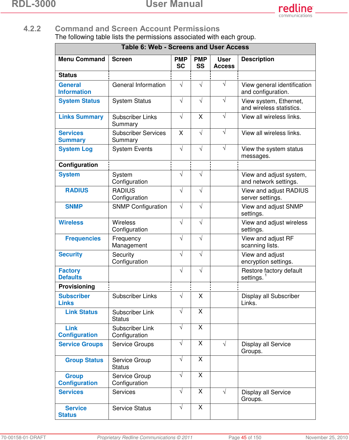
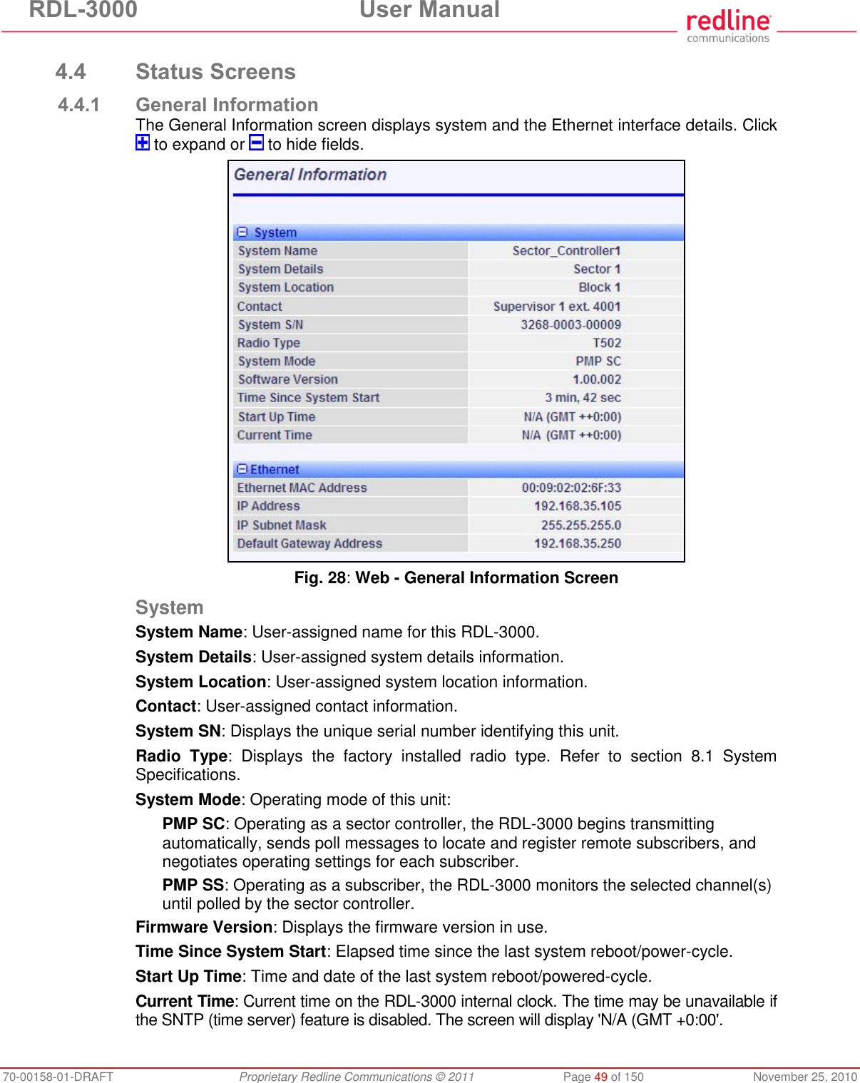
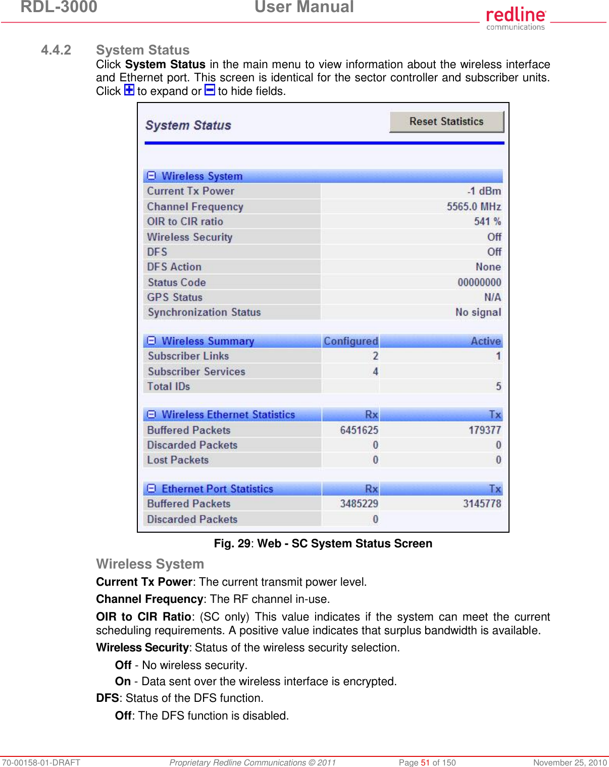
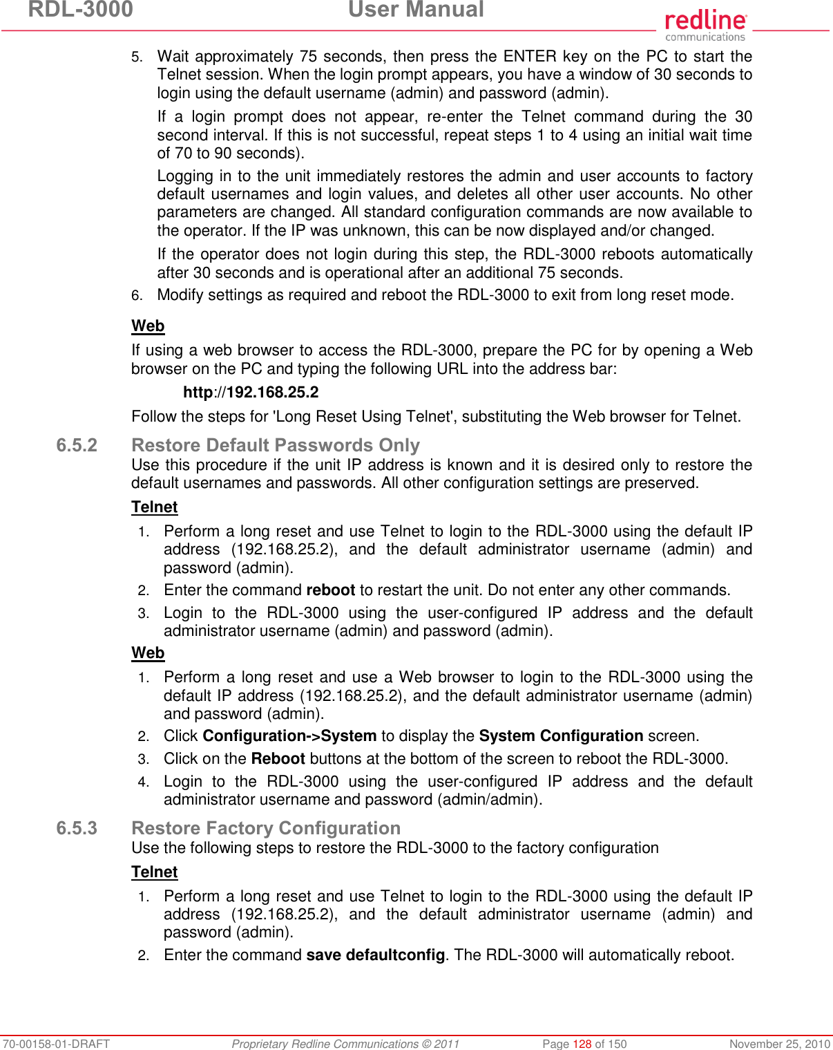
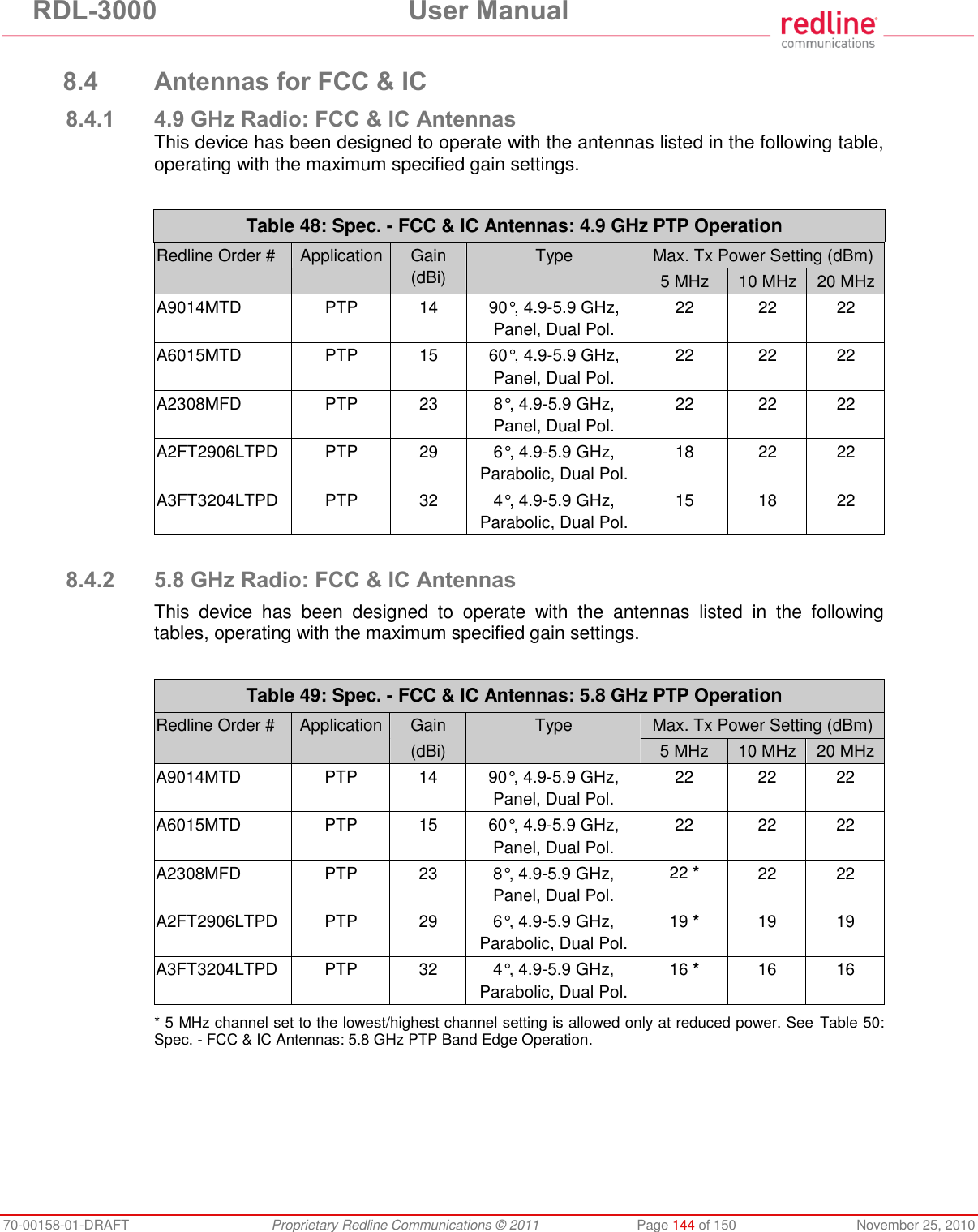
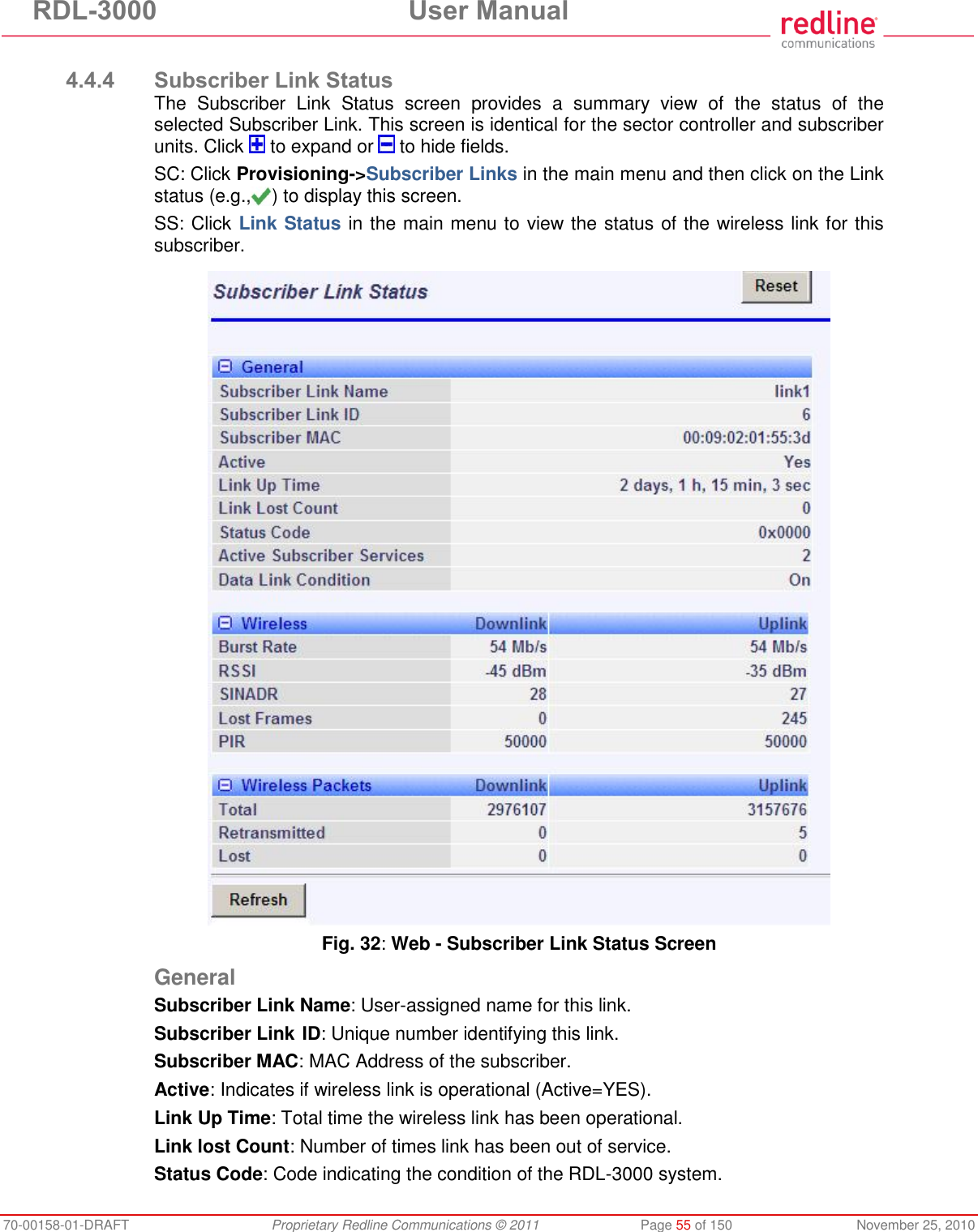
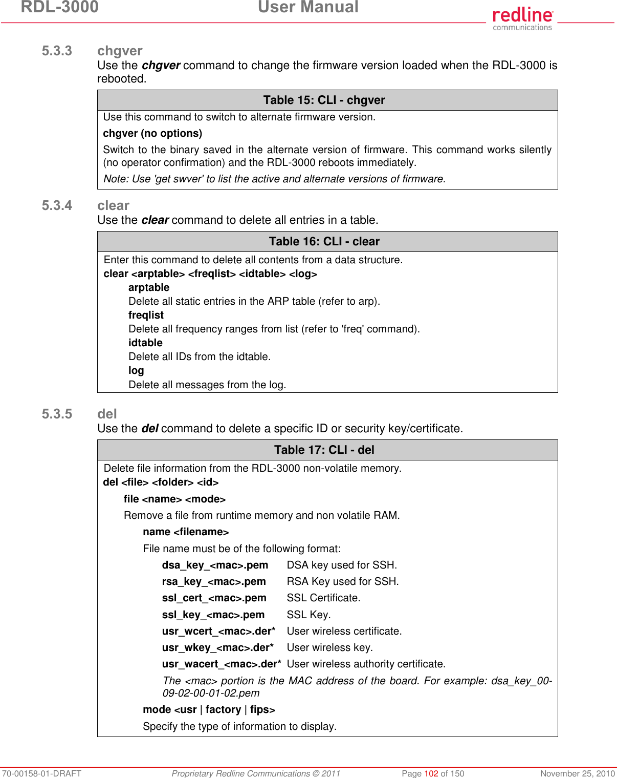
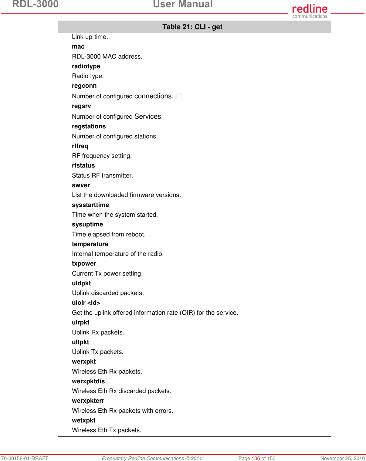
![RDL-3000 User Manual 70-00158-01-DRAFT Proprietary Redline Communications © 2011 Page 54 of 150 November 25, 2010 4.4.3 Subscriber Links Summary Screen (SC Only) Click Links Summary in the main menu (SC) to view the status of all wireless links. This screen is available only on subscriber units. Fig. 31: Web - Subscriber Links Summary Screen Name: Operator-assigned name for wireless Links and related Services. Click on a Subscriber Link name (e.g., Link1) to display the Link Configuration screen ID/Status: Subscriber Link identifier and status indicator. ID: A unique numeric ID generated automatically when the Subscriber Link was created. This value is required when using the CLI interface to modify Link settings. Status: Graphic indication of the status of this link or Service. Click on the symbol to display the Subscriber Link Status screen. The link or Service is available. The link or Service is unavailable (offline or disabled). SINADR [dB]: Ratio of the average RF signal strength to interference, noise, and distortion. DL: SINADR reported by the remote end unit. UL: Received signal strength to noise measured by this unit. RSSI [dBm]: Received signal strength indicator. DL: RSSI reported by the remote end unit. UL: Received signal strength measured by this unit. Burst Rate [Mb/s]: The current uplink and downlink uncoded burst rate for the link. DL: Operator-assigned maximum downlink burst rate setting. UL: Operator-assigned maximum uplink burst rate setting. Total Wireless Packets: Total packets successfully processed over the wireless interface. Total does not include discarded or errored packets. DL: Total packets transmitted over the wireless interface. UL: Total packets received over the wireless interface. Retransmitted Wireless Packets: Total number of wireless packets that have been retransmitted over the wireless interface. DL: Total packets retransmitted over the wireless interface. UL: Total packets retransmitted by the remote end.](https://usermanual.wiki/Redline-Communications/RDL3000A/User-Guide-1577952-Page-54.png)
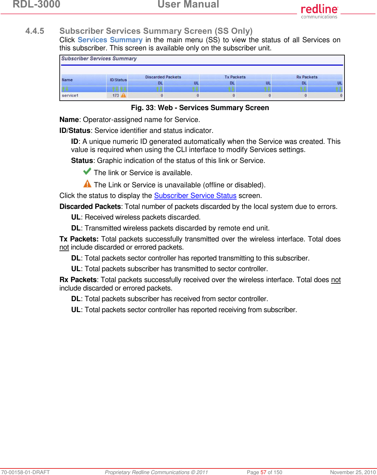
![RDL-3000 User Manual 70-00158-01-DRAFT Proprietary Redline Communications © 2011 Page 56 of 150 November 25, 2010 Configured Subscriber Services: The number of Services provisioned on this link. Wireless The following statistics are displayed for the downlink and uplink. Burst Rate: The current uncoded burst rate for the link. RSSI: Received signal strength indicator. SINADR: Average signal to interference, noise, and distortion ratio. Lost Frames: Number of frames lost. Wireless Packets The following statistics are displayed for the downlink and uplink. Total: Total packets successfully processed over the wireless interface. Total does not include discarded or errored packets. Retransmitted: Total number of wireless packets that have been retransmitted over the wireless interface. Lost: Total packets discarded by the local system due to errors. SINADR [dB]: Ratio of the average RF signal strength to interference, noise, and distortion. DL: SINADR reported by the remote end unit. UL: Received signal strength to noise measured by this unit. RSSI [dBm]: Received signal strength indicator. DL: RSSI reported by the remote end unit. UL: Received signal strength measured by this unit. Burst Rate [Mb/s]: The current uplink and downlink uncoded burst rate for the link. DL: Operator-assigned maximum downlink burst rate setting. UL: Operator-assigned maximum uplink burst rate setting. Controls Refresh: Click to update displayed statistics counters. Reset: Click to reset displayed statistics counters.](https://usermanual.wiki/Redline-Communications/RDL3000A/User-Guide-1577952-Page-56.png)
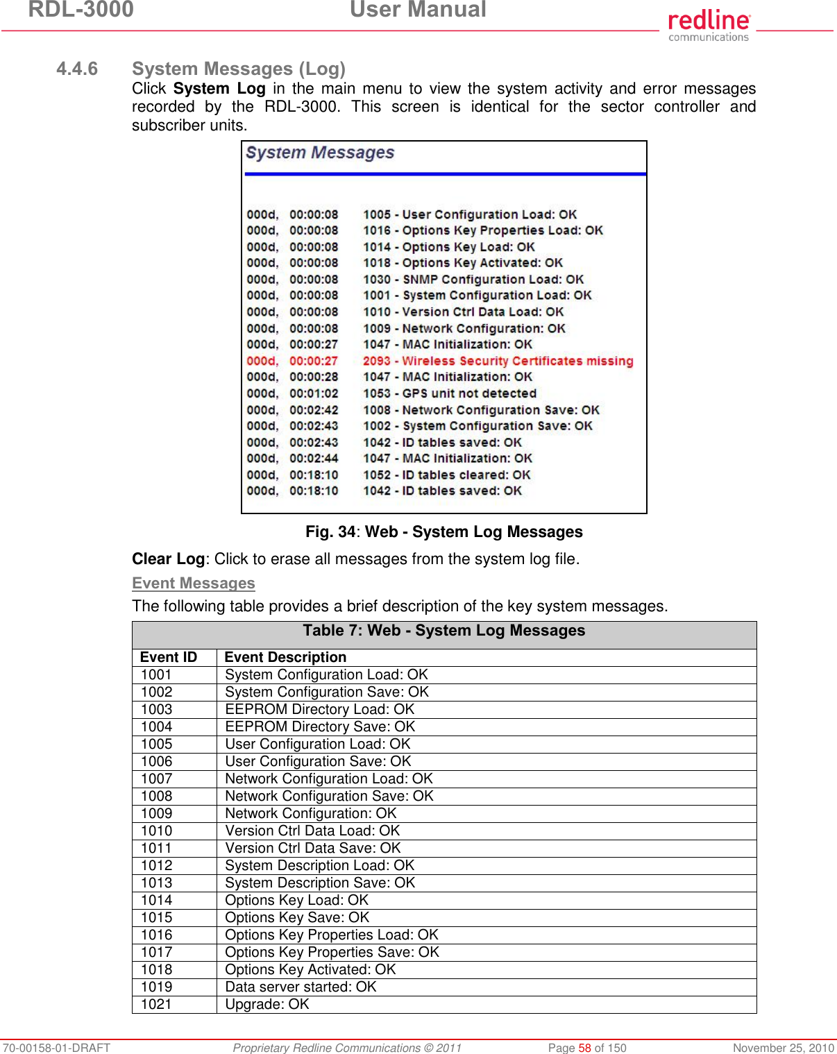
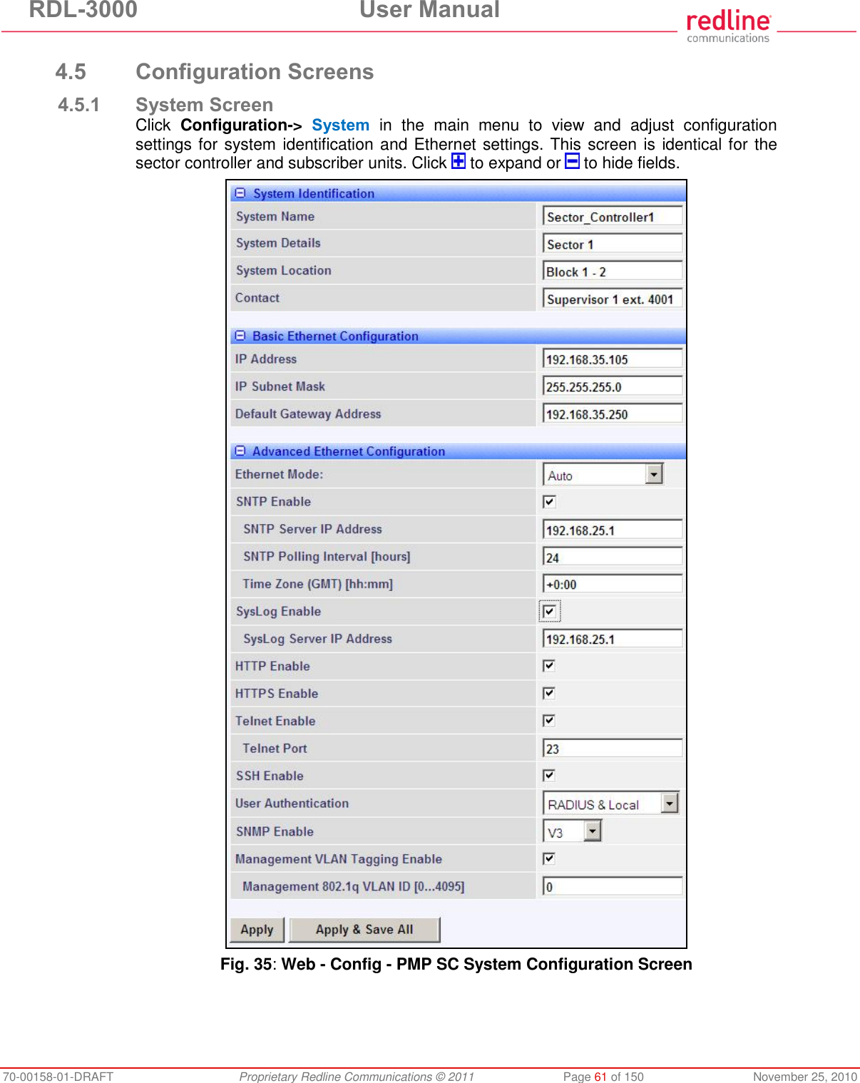
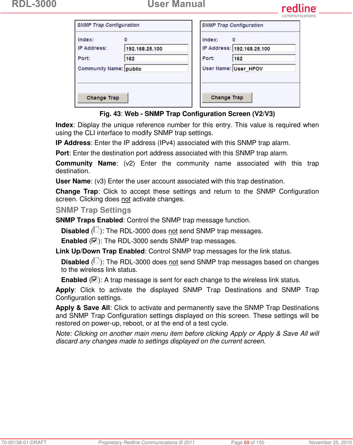
![RDL-3000 User Manual 70-00158-01-DRAFT Proprietary Redline Communications © 2011 Page 62 of 150 November 25, 2010 System Identification System Name: Enter the name for this RDL-3000. The system name may be up to thirty alpha-numeric characters including a-z, A-Z, 0-9, dash (-), and underscore (_). System Details: Enter additional descriptive details about this RDL-3000. The system details may be up to thirty alpha-numeric characters including a-z, A-Z, 0-9, dash (-), and underscore (_). System Location: Enter additional descriptive details about this RDL-3000. The system location information may be up to thirty alphanumeric characters including a-z, A-Z, 0-9, dash (-), and underscore (_). Contact: Enter additional descriptive details about this RDL-3000. The contact information may be up to thirty alpha-numeric characters including a-z, A-Z, 0-9, dash (-), and underscore (_). Basic Ethernet Configuration IP Address: Enter the IP address for this RDL-3000. The IP address is routable both through the Ethernet port and over the wireless interface. IP Subnet Mask: Enter the IP subnet mask. Default Gateway Address: Enter the IP address of the default gateway or router on the Ethernet segment connected to the RDL-3000 Ethernet port. Advanced Ethernet Configuration Ethernet Mode: Select the operating mode of the Ethernet port. Auto - Automatically negotiate the connection speed and duplex. 10Mbps HD - Operate at 10Base-T half-duplex only. 10Mbps FD - Operate at 10Base-T full duplex only. 100Mbps HD -.Operate at 100Base-T half-duplex only. 100Mbps FD - Operate at 100Base-T full duplex only. Important: The auto-negotiate function works correctly only when both communicating Ethernet devices are configured for auto-negotiate. The auto-negotiate feature does not detect the speed and duplex of Ethernet equipment operating at a fixed speed and duplex. Duplex mismatches may result in an unexpected loss of communications. It is recommended to set the Ethernet ports to operate at a fixed speed of 100Base-T using full duplex. SNTP Enable: Check this box to enable the SNTP protocol support. This feature allows RDL-3000 systems to time-stamp log messages using a network time server. When enabled, you must enter the network address of the SNTP server in the SNTP Server IP Address field. When SNTP is enabled, the following additional configuration fields are visible: SNTP Server IP Address: Enter the network address of the SNTP server. SNTP Polling Interval [hours]: Enter the SNTP polling interval (hours). Time Zone (GMT) [hh:mm]: Enter the hours offset from GMT for this time zone. Syslog Enable: Check this box to enable the Syslog protocol support. This feature allows RDL-3000 log messages to be saved in a central repository. When enabled, you must enter the network address of the Syslog server in the Syslog Server IP Address field. When Syslog is enabled, the following additional configuration field is visible: Syslog Server IP Address: Enter the network address of the Syslog server. HTTP Enable: Check this box to enable the HTTP (Web) interface.](https://usermanual.wiki/Redline-Communications/RDL3000A/User-Guide-1577952-Page-62.png)
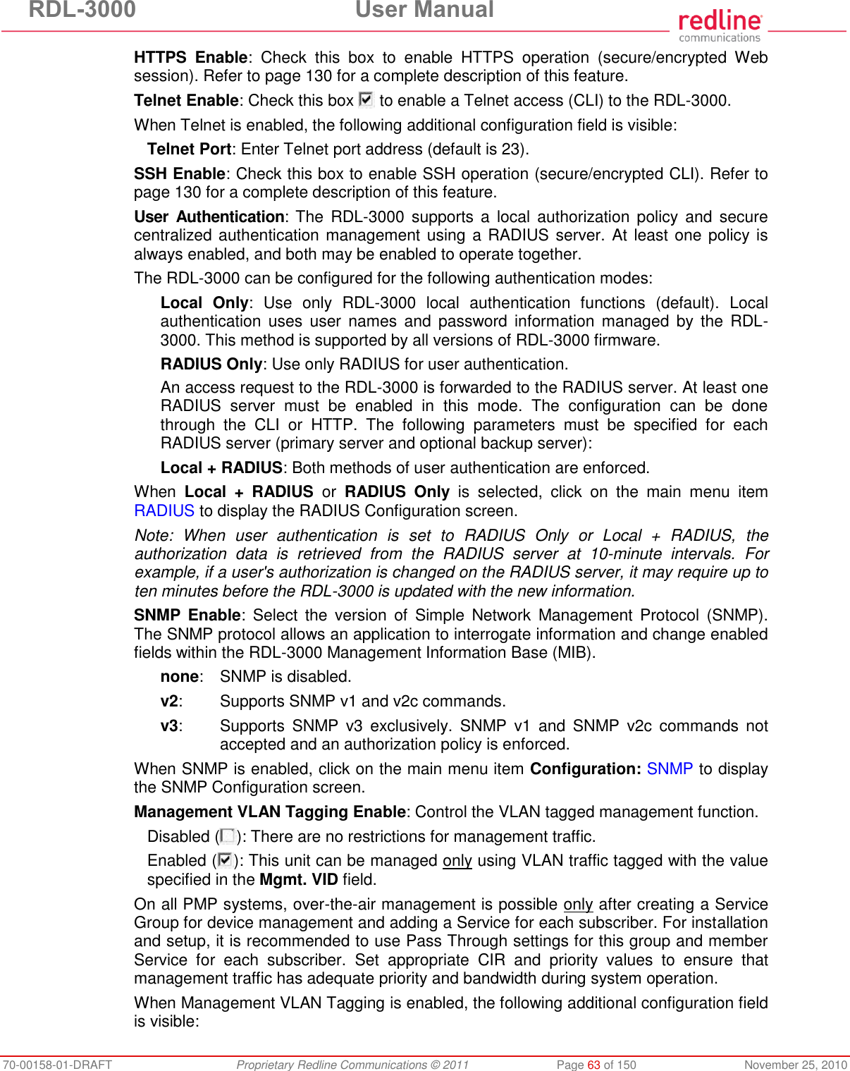
![RDL-3000 User Manual 70-00158-01-DRAFT Proprietary Redline Communications © 2011 Page 64 of 150 November 25, 2010 Management 802.1Q VLAN ID [0...4095]: Enter the management VLAN ID. When Management VLAN Tagging Enable is selected, the system recognizes only management commands where the Ethernet packet has this VLAN ID. Important: If the Management VLAN Tagging feature is required, it is recommended to test the VLAN connectivity before activating this function. Otherwise, the RDL-3000 unit may become unmanageable require a long reset operation to recover control. Fig. 36: Web - VLAN Tagged Management Example In the following example, the network management VLAN ID=600. Identical settings are used on the Service Group and each subscriber Service. Click to display the Services associated with each Service Group. Fig. 37: Web - VLAN Tagged Management Example](https://usermanual.wiki/Redline-Communications/RDL3000A/User-Guide-1577952-Page-64.png)
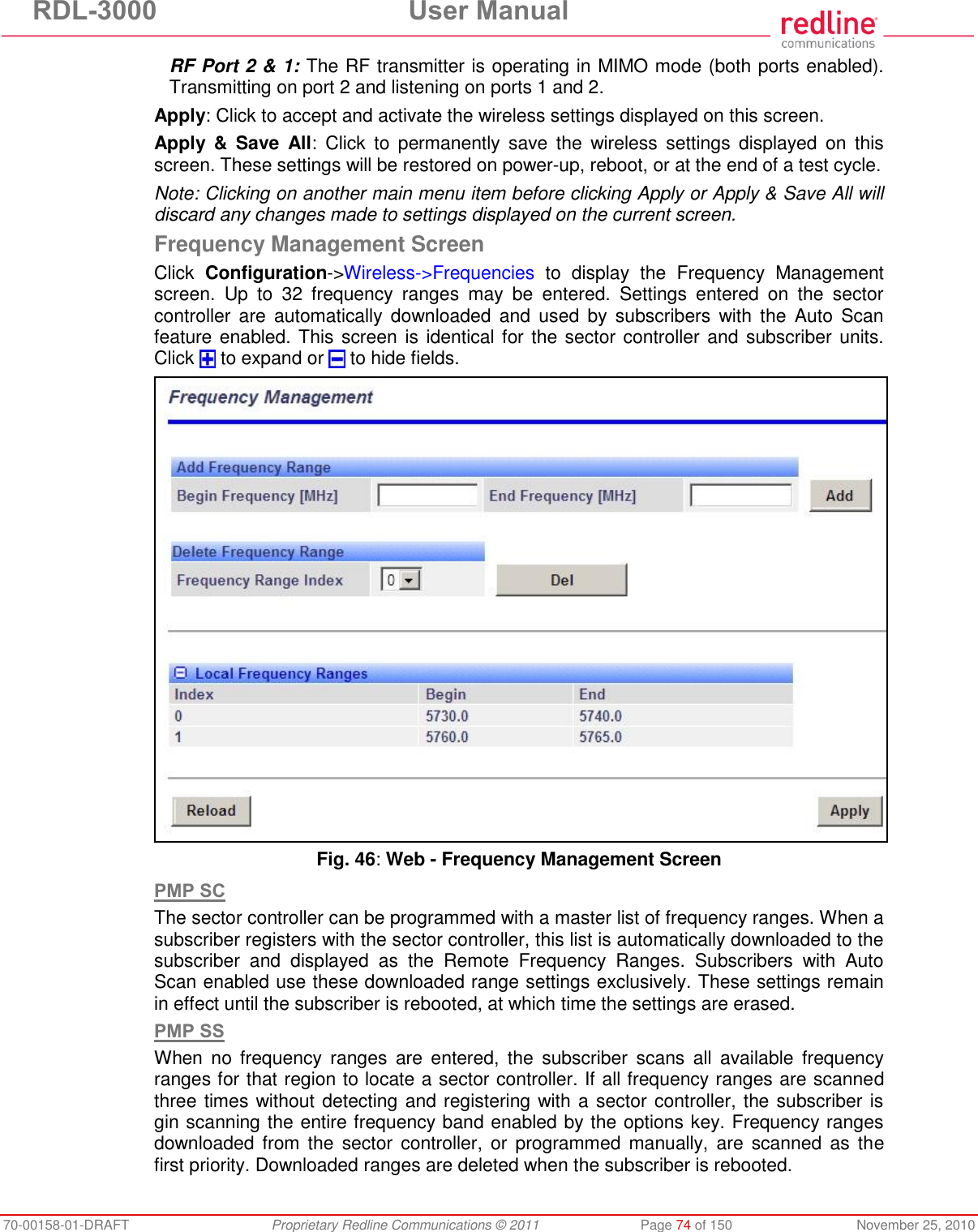
![RDL-3000 User Manual 70-00158-01-DRAFT Proprietary Redline Communications © 2011 Page 70 of 150 November 25, 2010 4.5.4 Wireless Configuration Use these settings to configure the RDL-3000 wireless interface. This screen is different on the sector controller and subscriber unit. Click to expand or to hide fields. Fig. 44: Web - Wireless Configuration Screen -- Sector Controller Basic Wireless Configuration System Mode: The system designated as sector controller establishes and manages the bi-directional data link with a remote end RDL-3000. Only one system in a wireless link must be set for Sector Controller mode (PMP SC). PMP SC: RDL-3000 automatically sends poll messages to locate and register remote RDL-3000 subscribers, and negotiates operating settings for the link. PMP SS: RDL-3000 monitors the selected channel(s) until polled by the PMP Sector Controller. Channel Width [MHz]: Select the channel bandwidth. The options key controls channel availability.](https://usermanual.wiki/Redline-Communications/RDL3000A/User-Guide-1577952-Page-70.png)
![RDL-3000 User Manual 70-00158-01-DRAFT Proprietary Redline Communications © 2011 Page 71 of 150 November 25, 2010 RF Freq. [MHz]: Enter the center frequency for the RF channel. The options key controls channel availability. Use the Auto scan feature to enable subscribers to scan multiple channels. Important: To minimize interference between RDL-3000 links operating in close proximity, RF frequency settings should be separated by a guard interval equal or greater than the channel size. For example, when using a 20 MHz channel, the RF frequencies should be separated by >20 MHz. Fig. 45: Web - Wireless Configuration Screen -- Subscriber Auto scan: (Subscriber Only) Check this box to enable the subscriber to automatically scan available channels to locate and register with an RDL-3000 PMP Master. When Auto scan is not enabled, the wireless link can be established only at the frequency specified in the RF Freq. [MHz] field. By default, the subscriber will scan the entire frequency band enabled by the options key (see section 8.3: Regional Codes on page 142). To reduce the scanning/connection time, the operator may specify a subset of frequency ranges to scan. Click on the main menu item Configuration -> Frequencies to display the Frequency Management screen. Tx Power [dBm]: Enter the transmit power level (dBm). This setting is for the transceiver output only. The actual EIRP depends on the gain of the connected antenna. See the following tables to determine the maximum transmit power level available at each modulation setting. When DFS is enabled, the subscriber Tx power may be adjusted automatically to avoid falsely triggering the DFS feature. Table 9: Web - Maximum TX Power Settings (dBm) for All Modes Modulation BPSK QPSK 16 QAM 64 QAM Code Rate 1/2 3/4 1/2 3/4 1/2 3/4 2/3 3/4 Max. Tx Power 25 25 25 25 23 23 22 22](https://usermanual.wiki/Redline-Communications/RDL3000A/User-Guide-1577952-Page-71.png)
![RDL-3000 User Manual 70-00158-01-DRAFT Proprietary Redline Communications © 2011 Page 72 of 150 November 25, 2010 Important: EIRP Levels: Where required by local regulations, the maximum operational power per channel for a specific antenna must not exceed the maximum allowable EIRP levels. See the FCC and CE notices in this manual. The RF output power settings must be professionally programmed by the manufacturer or a trained professional installer who is knowledgeable of and follows the local and regional regulatory RF requirements. Advanced Wireless Configuration Max. Distance [km]: (SC only) Enter the distance to the subscriber located farthest away from the sector controller (outer boundary of sector). DFS Action: (SC only) Select the mode of operation for DFS. The PMP SC monitors for interference from radar devices and other equipment using the same channel frequency. When interference is detected, the PMP SC automatically takes the selected action: None: The DFS function is disabled. Where DFS is required by regional regulations, this feature is permanently enabled at the factory and can not be disabled by the installer or end-user. Tx Off: When radar signals are detected the transmitter is switched off for 30 minutes. This action is recorded in the message log and an SNMP trap message is sent (if SNMP enabled). Following an interval of thirty minutes, the same channel is monitored for one minute and if there are no DFS triggering events, the system resumes normal operation. If DFS trigger conditions are still detected, operation is suspended for an additional thirty minute period. Chg Freq: When radar signals are detected the transmitter is switched to a different frequency. This action is logged and a trap message is sent (if enabled). A new channel is selected based on allowable frequencies for the regulatory region set by the active options key. Each selected channel is monitored for one minute, and if DFS triggering events are detected, the next available channel is selected. The system is not allowed to return to a channel on which DFS trigger events were detected for a period of thirty minutes. If DFS trigger events are detected on all channels, operation is suspended until the time expires for at least one channel. Antenna Gain: Enter the antenna gain specified by the manufacturer. This field is required for DFS-enabled systems. It is important to enter the correct value. If this value is set higher than the true gain, the sensitivity is too low and the RDL-3000 will not be operating in compliance with the UK/ETSI standard. If this value is set lower than the true gain, the RDL-3000 is more sensitive to interference and may experience false triggers. Antenna Alignment Buzzer Enable: (SS only) Audible antenna alignment tool. Disabled ( ): The antenna alignment tool is disabled (no tone). Enabled ( ): The antenna alignment audible tone generator is active. The rate of the tone increases when a stronger signal is detected. Registration Period [frames]: (SC only) The polling period for detecting new subscribers. This period is based on the number of wireless frames transmitted. Permitted values are 1 to 100 frames (recommended frame period: 4). Scheduling Cycle: Enter the duration of the traffic scheduling period (e.g., 5 ms). This setting affects the volume (and latency) of traffic transmitted over the wireless interface during each cycle. Longer scheduling cycles can provide more efficient packet processing.](https://usermanual.wiki/Redline-Communications/RDL3000A/User-Guide-1577952-Page-72.png)
![RDL-3000 User Manual 70-00158-01-DRAFT Proprietary Redline Communications © 2011 Page 73 of 150 November 25, 2010 Shorter scheduling cycles can provide lower latency: DL latency: Avg. 0.5/ Max. 2 * Scheduling Cycle UL latency: Avg. 0.5/ Max. 3 * Scheduling Cycle Note: The effects of changes to the scheduling cycle will vary based aggregate traffic composition (packet rate, packet size, etc). Fixed Frame: Select the wireless frame mode. Disabled ( ): RDL-3000 adjusts the wireless frame size dynamically based on uplink and downlink traffic patterns. Enabled ( ): Wireless frame size is fixed at the value specified in the Frame Size field. Fixed frame mode must be used when using synchronization (collocated base stations). The Fixed Frame size and Downlink Ratio must be identical for all synchronized base stations operating in a geographical area. When fixed frame mode is enabled, the PIR is limited as follows: Max PIR = CIR * Scheduling Cycle / Frame Size Frame Size [ms]: When Fixed Frame mode is selected, the frame size must be specified (1 to 20 milliseconds). Downlink Ratio [%]: (SC only) When Fixed Frame mode is selected, the proportion of each frame reserved for downlink data must be specified (20-80 %). Synchronization Mode: (SC only) When Fixed Frame mode is selected, the synchronization mode must be specified. None: Synchronization is disabled. Internal: Transmissions are synchronized to the RDL-3000 internal clock. If a GPS module is installed and synchronized to one or more satellites, transmissions are synchronized to the module 1 PPS output. External: Synchronize this unit to a 1 PPS signal received on the PPS port. Synchronization Output: (SC only) When Fixed Frame mode is selected, the synchronization output port (PPS) mode must be specified. Disabled ( ):The PPS port is disabled. Enabled ( ): The synchronization port output is active. The synchronization output port (PPS) termination must be specified. Synchronization Output Termination: (SC only) When the synchronization port (PPS) output is enabled, the impedance must be specified. When collocated RDL-3000 units have the PPS ports cabled together for synchronization, only the last RDL-3000 in the daisy-chain should have the termination set to 50 or 75 ohms (based on cable type). Refer to the RDL-3000 Installation Guidelines for more information. None: Port termination is high impedance. 50 Ohms: Port termination impedance is 50 Ohms. 75 Ohms: Port termination impedance is 75 Ohms. Radio Enable: Select the operational mode for the antenna system. Off: RF Port 1 and RF port 2 radio transmitters are disabled (no RF output). RF Port 1: The RF transmitter on RF Port 1 is enabled (RF port 2 is disabled). RF Port 2: The RF transmitter on RF Port 2 is enabled (RF port 1 is disabled). RF Port 1 & 2: The RF transmitter is operating in MIMO mode. Transmitting on port 1 and listening on ports 1 and 2.](https://usermanual.wiki/Redline-Communications/RDL3000A/User-Guide-1577952-Page-73.png)
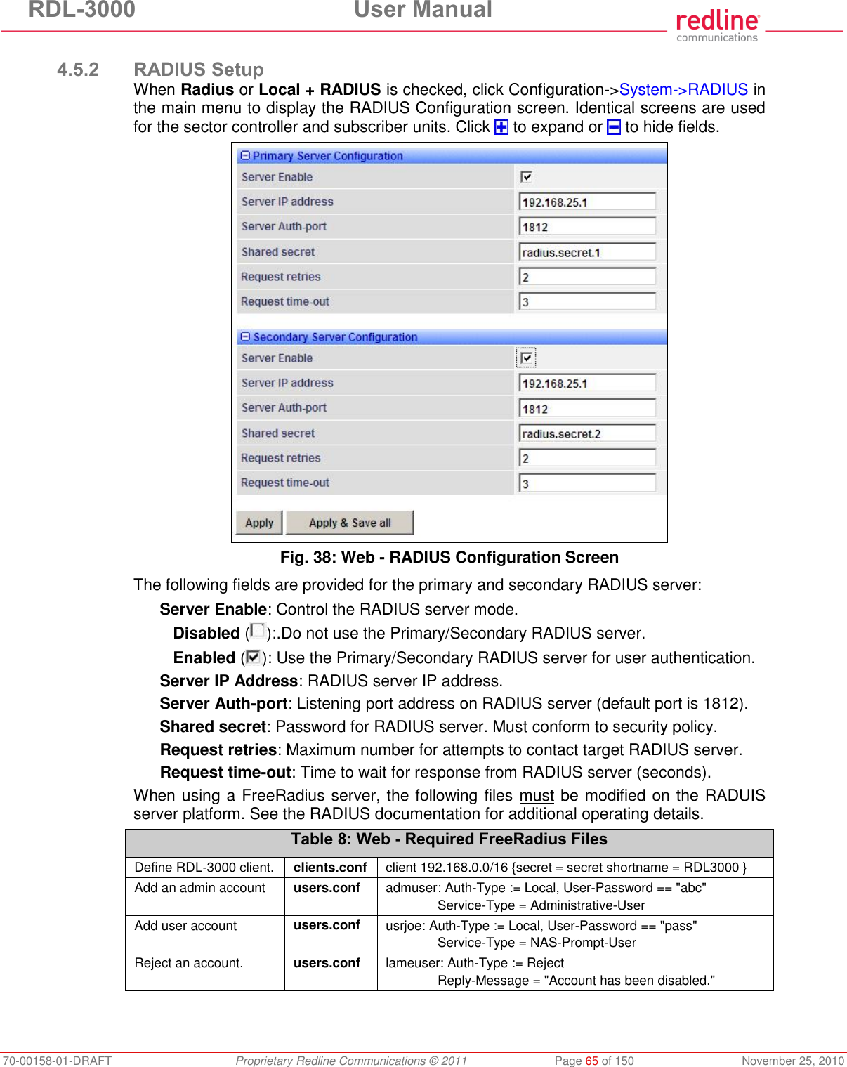
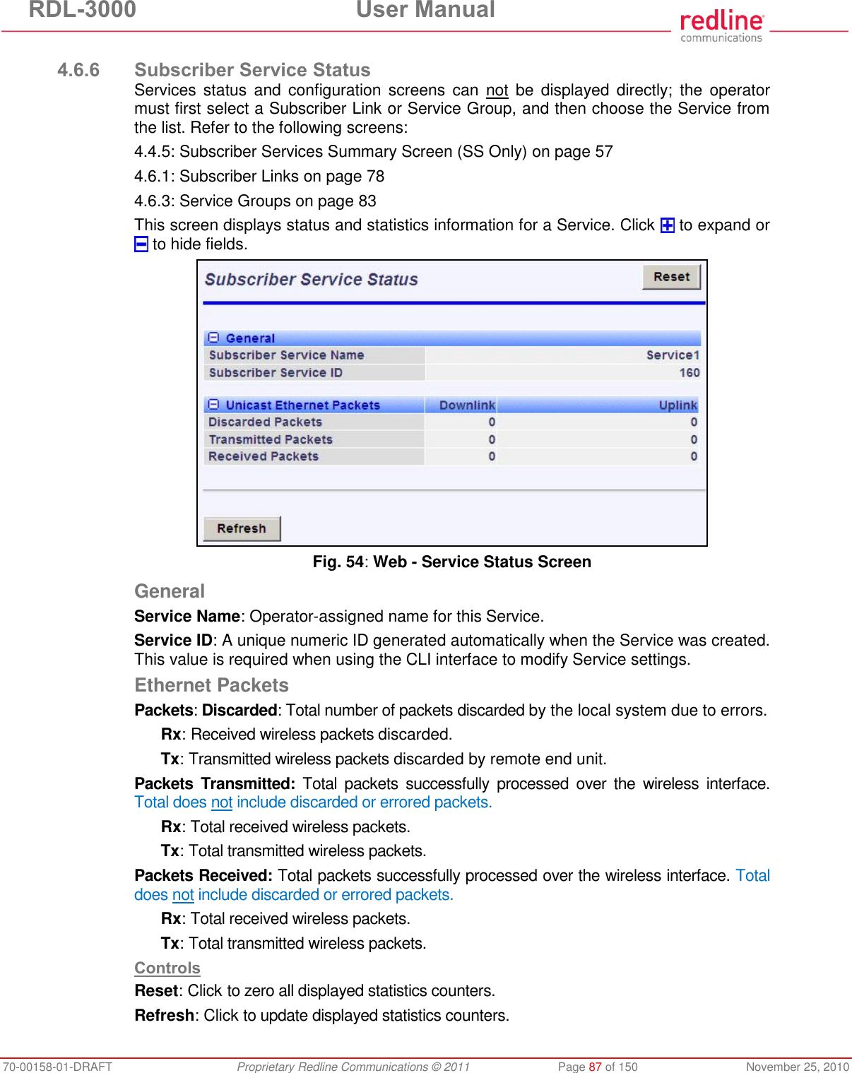
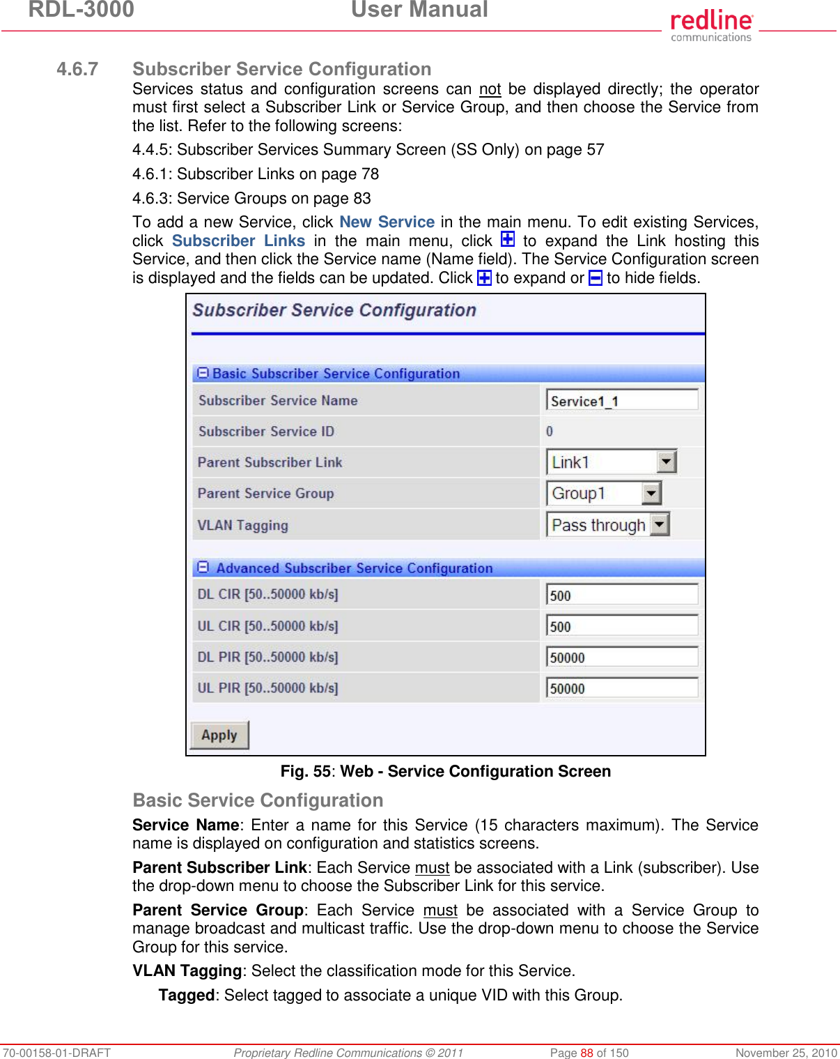
![RDL-3000 User Manual 70-00158-01-DRAFT Proprietary Redline Communications © 2011 Page 85 of 150 November 25, 2010 4.6.5 Service Group Configuration Use this screen to create new Service Groups or view/modify existing Service Groups. Click Service Groups in the main menu, locate the desired Service Group in the table, and click on the Service Group name (Name column) to display this screen. Click to expand or to hide fields. Fig. 53: Web - Service Group Configuration Screen Basic Service Group Configuration Service Group Name: Enter a unique name to identify this Service group. This identifier is displayed on configuration and statistics screens. The name may contain up to fifteen (15) alpha-numeric characters including a-z, A-Z, 0-9, dash (-), and underscore (_). Service Group ID: (Read only) A unique numeric ID generated automatically when a Service Group is created. This value is required when using the CLI interface to modify Service Group settings. VLAN Tagging: Select the classification mode for this Service Group. Tagged: Select tagged to associate a unique VID with this Group. Pass-through: Classify all packets that do not have a VLAN ID, or where the outermost VLAN ID tag does not match the VLAN ID for any tagged Group. Ethernet ingress port are discarded. 802.1Q VLAN ID [0-4095]: Enter the VID associated with this Group definition. This field is used only when 'Tagged' is selected in the Group Tagging Mode field. Default Priority: Enter the default 802.1p priority setting.](https://usermanual.wiki/Redline-Communications/RDL3000A/User-Guide-1577952-Page-85.png)
![RDL-3000 User Manual 70-00158-01-DRAFT Proprietary Redline Communications © 2011 Page 86 of 150 November 25, 2010 The default priority is used to set the 802.1p priority field when a Service Group is set to Tagged mode (add VLAN tag) and no priority information was received with the packet. Advanced Service Group Configuration SC Ethernet Port Enable: Controls the function of the sector controller Ethernet port for group multicast traffic. Enabled ( ): Broadcast and multicast traffic received from subscribers is forwarded over the sector controller Ethernet port. Disabled ( ): Broadcast and multicast traffic received from subscribers is not forwarded over the sector controller Ethernet port. SS To SS Broadcast and multicast Enable: Enabled ( ): Broadcast and multicast traffic received from subscribers is forwarded over the wireless interface to all subscribers associated with the group. Disabled ( ): Broadcast and multicast traffic received from subscribers is not forward over the wireless interface. Burst Rate: Enter the uncoded burst rate for downlink broadcast and multicast traffic belonging to this Group. Use the 'Auto' setting (recommended) to have the rate selected automatically based on the current operating conditions. To set this to a fixed value, first identify the group member having the lowest Max DL Burst Rate setting, and then calculate the rate using the formula: Burst_Rate = Max DL Burst Rate - 1 Note: Applications requiring a higher broadcast or multicast rate (e.g., video) may use a higher setting at the risk of less reliable retransmissions. DL Bcast/Mcast CIR [50..50000 Kbps]: Set the CIR for downlink broadcast and multicast traffic belonging to this group. DL Bcast/Mcast PIR [50..50000 Kbps]: Set the PIR for downlink broadcast and multicast traffic belonging to this group. Note: Traffic transmitted over the wireless interface is monitored to enforce CIR/PIR settings. Traffic statistics are reset at the beginning of each common one-second clock tick. When adaptive modulation is enabled, automatic adjustments to the modulation/coding will result in relative changes to the CIR/PIR of that wireless link. Controls Apply: Click to accept and activate displayed settings.](https://usermanual.wiki/Redline-Communications/RDL3000A/User-Guide-1577952-Page-86.png)
![RDL-3000 User Manual 70-00158-01-DRAFT Proprietary Redline Communications © 2011 Page 89 of 150 November 25, 2010 Pass-through: Classify all packets that do not have a VLAN tag, or where the outermost VLAN ID tag does not match the VLAN ID for any tagged Group. 802.1Q VLAN ID [0-4095]: Enter the VID associated with this Group definition. This field is used only when 'Tagged' is selected in the Group Tagging Mode field. Default Priority: Enter the default 802.1p priority setting. The default priority is used to set the 802.1p priority field when a Service is set to Tagged mode (add VLAN tag) and no priority information was received with the packet. Advanced Service Configuration DL CIR: Enter the committed information rate for downlink unicast traffic. UL CIR: Enter the committed information rate for uplink unicast traffic. DL PIR: Enter the peak information rate for downlink unicast traffic. UL PIR: Enter the peak information rate for uplink unicast traffic The traffic each Service transmits over the wireless interface is monitored to enforce PIR settings (50 - 50000 Kbps). Traffic statistics are reset at the beginning of each common one-second clock tick. If the maximum throughput is reached on any Service before the end of the current interval, that Service is excluded from sending additional traffic until after the next clock tick. For example, if a Service transmits its full data allocation in the first 650 ms of the current metering interval, that Service will not receive any additional bandwidth allocation until the beginning of the next interval (enforced pause of 350 ms). When adaptive modulation is enabled, automatic adjustments to the modulation/coding will result in relative changes to the PIR of all Services and Service Groups using that wireless link. Incorrect PIR settings may result in excessive latency or dropped packets (buffer full condition). Controls Apply: Click to accept and activate displayed settings.](https://usermanual.wiki/Redline-Communications/RDL3000A/User-Guide-1577952-Page-89.png)
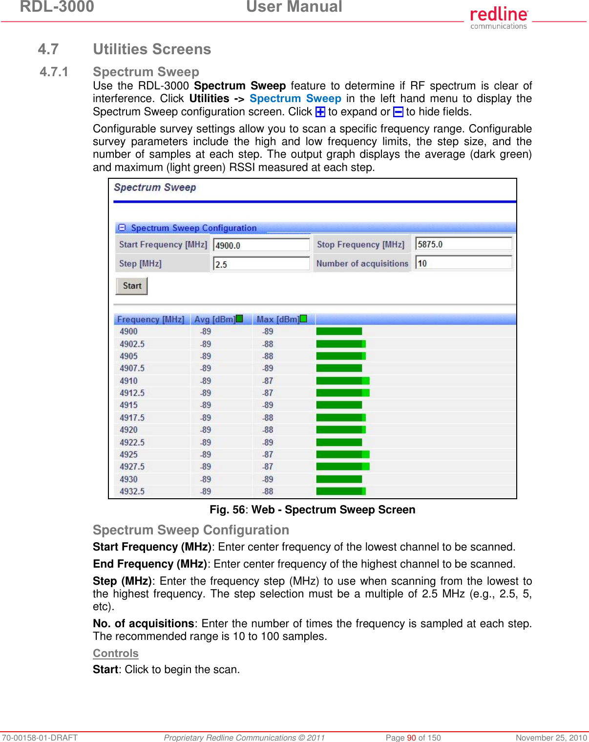
![RDL-3000 User Manual 70-00158-01-DRAFT Proprietary Redline Communications © 2011 Page 91 of 150 November 25, 2010 Spectrum Sweep Chart Frequency (MHz): Center frequency of the scanned channel. Ave (dBm): Average measured signal for all samples. Max (dBm): Maximum measured signal for all samples. Bar Graph: Graph of average (dark green) and peak (light green) results. Performing a Sweep 1. Prepare the RDL-3000: For PMP sector controllers, the transmitter is disabled automatically during a sweep. Note: To run a sweep from a PMP Subscriber location, the sector controller transmitter must be disabled for the duration of the test. 2. Click Wireless Spectrum Sweep in the main menu. It is recommended to scan using the smallest available channel with a step size of 1/2 the planned channel size (e.g., use a 5 MHz step size when scanning for a free 10 MHz channel). For example: Start/Stop = 5735 / 5830 Step [MHz] = 5 No. of Acquisitions = 10 3. Click Start button to begin the sweep. 4. Review the results. A channel may be considered 'clear' when free of interference for at least +/- one-half the channel bandwidth from the desired center frequency. For example, a 20 MHz channel should have no interference detected for at least +/- 10 MHz from the candidate channel. When a potentially clear channel is identified, reduce the frequency range and step size while increasing the sample size to monitor the channel over a longer period.](https://usermanual.wiki/Redline-Communications/RDL3000A/User-Guide-1577952-Page-91.png)
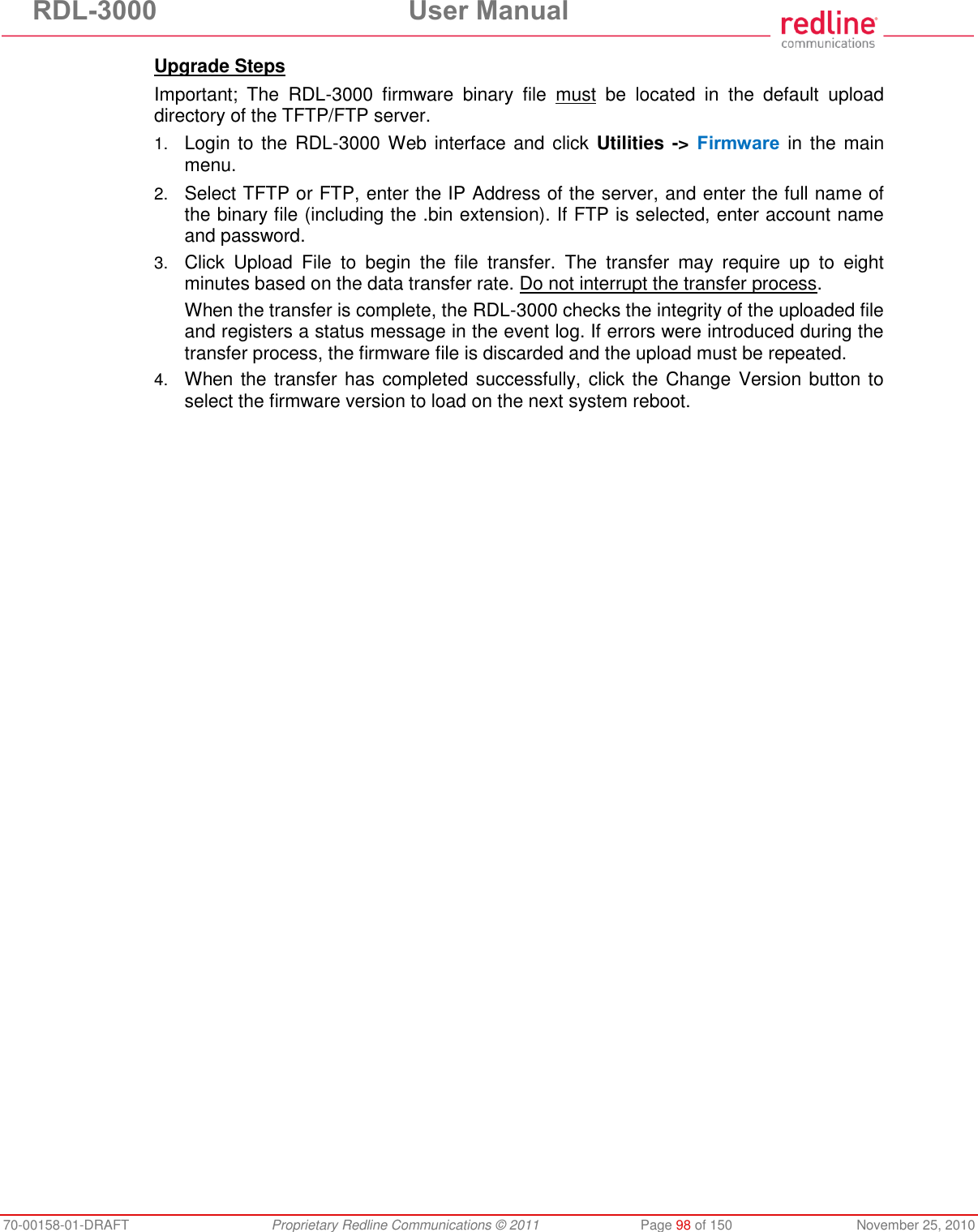
![RDL-3000 User Manual 70-00158-01-DRAFT Proprietary Redline Communications © 2011 Page 96 of 150 November 25, 2010 4.7.4 Antenna Alignment Screen Click Utilities -> Antenna Alignment in the main menu to display the Antenna Alignment Tool screen. This screen is used to assist when aligning the subscriber antenna. The most reliable method for obtaining optimum performance from a wireless link is by fine alignment of the antenna to the position providing the highest RSSI (Received Signal Strength Indication). This web page assists alignment by providing continuous updates of the current measured RSSI value. Fig. 59: Web - Antenna Alignment Tool Screen If Wi-Fi service is available, you may also be able to access the web alignment page directly from a laptop computer and most web-enabled handheld devices using the following URL: http:// [RDL-3000 IP Address] / usr / aa.html For example: http:// 192.168.20.25 / usr / aa.html](https://usermanual.wiki/Redline-Communications/RDL3000A/User-Guide-1577952-Page-96.png)
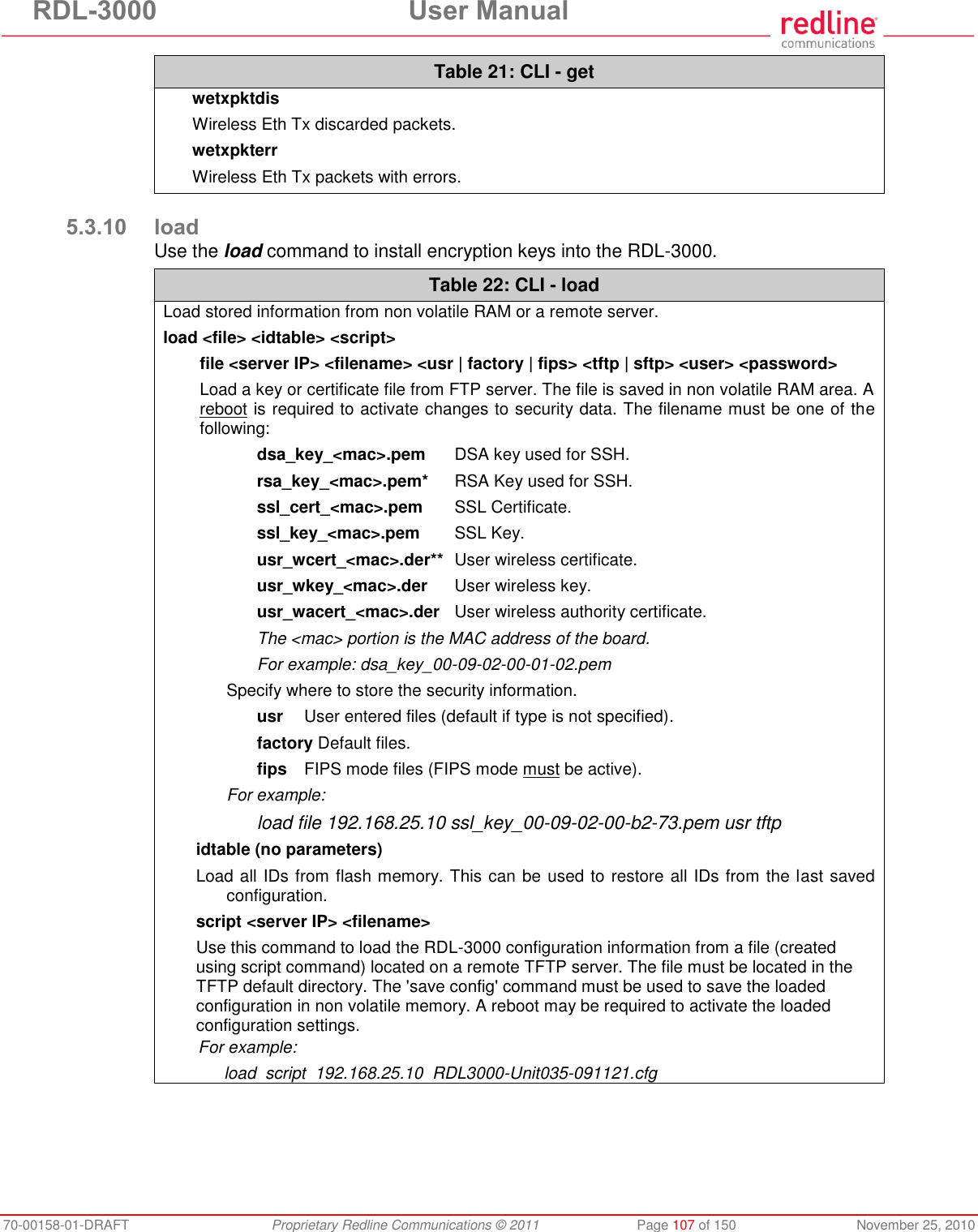
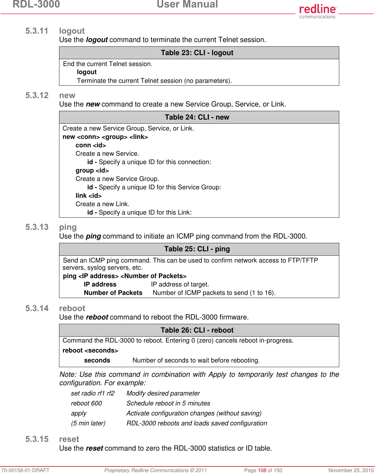
![RDL-3000 User Manual 70-00158-01-DRAFT Proprietary Redline Communications © 2011 Page 109 of 150 November 25, 2010 Table 27: CLI - reset Reset RDL-3000 values. reset <stats> Enter ID of specific Service, Service Group, or Link to be reset. stats <id> Reset statistics for a Service Group, Service, or Link. id - Specify an ID to reset statistics only for that Service Group, Service, or Link. Default is to reset all statistics. 5.3.16 save Use the save command to copy edited parameter settings into non-volatile memory. save [option] <Enter> Table 28: CLI - save Copy parameters to non-volatile memory. Does not affect security settings. save <config> <defaultconfig> <idtable> <snmp> config Save Ethernet, wireless, and user configuration settings. defaultconfig Overwrite parameters with the factory default settings. The following settings are not affected: system name, location, details and contact, frequency list, SNMP configuration, Idtable. idtable Save current idtable settings. snmp Save current SNMP settings. 5.3.17 script Use the script command to save a file containing a string of Commands that can be used to restore the current (active) configuration of the RDL-3000. Saved configuration files can be viewed, copied, and/or modified using a text editor. The file is saved in the TFTP default directory. The filename may be any name and extension valid for the TFTP server platform. It is recommended use a filename that uniquely identifies the RDL-3000 unit and the current date (e.g., Red80-AD0023-080723.cfg). See 'load' command. Table 29: CLI - script Create and save a script file containing all configuration settings. script <server> <name> server - TFTP server IP address name - Script file name Note: User account groups, usernames and passwords are not saved by the script command. Accounts must be created manually by a user using Telnet or a Web browser. The 'user' commands are interactive and can not be automated.](https://usermanual.wiki/Redline-Communications/RDL3000A/User-Guide-1577952-Page-109.png)
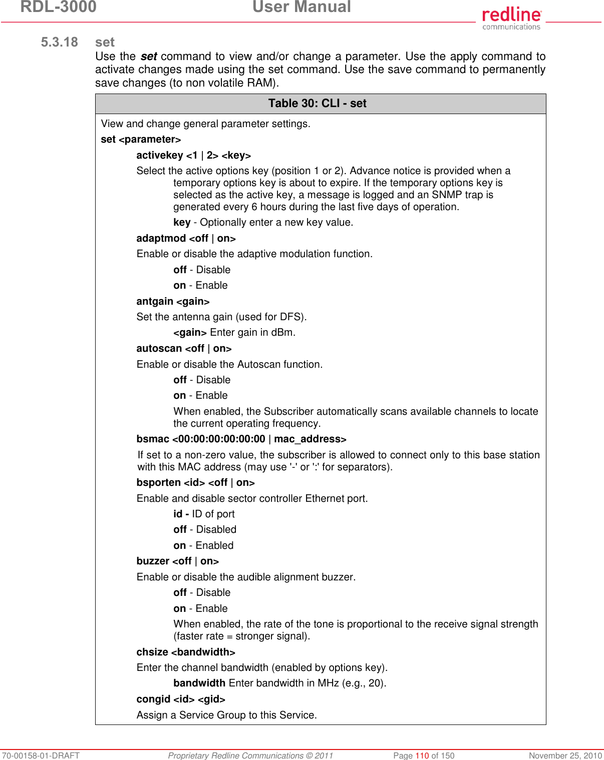
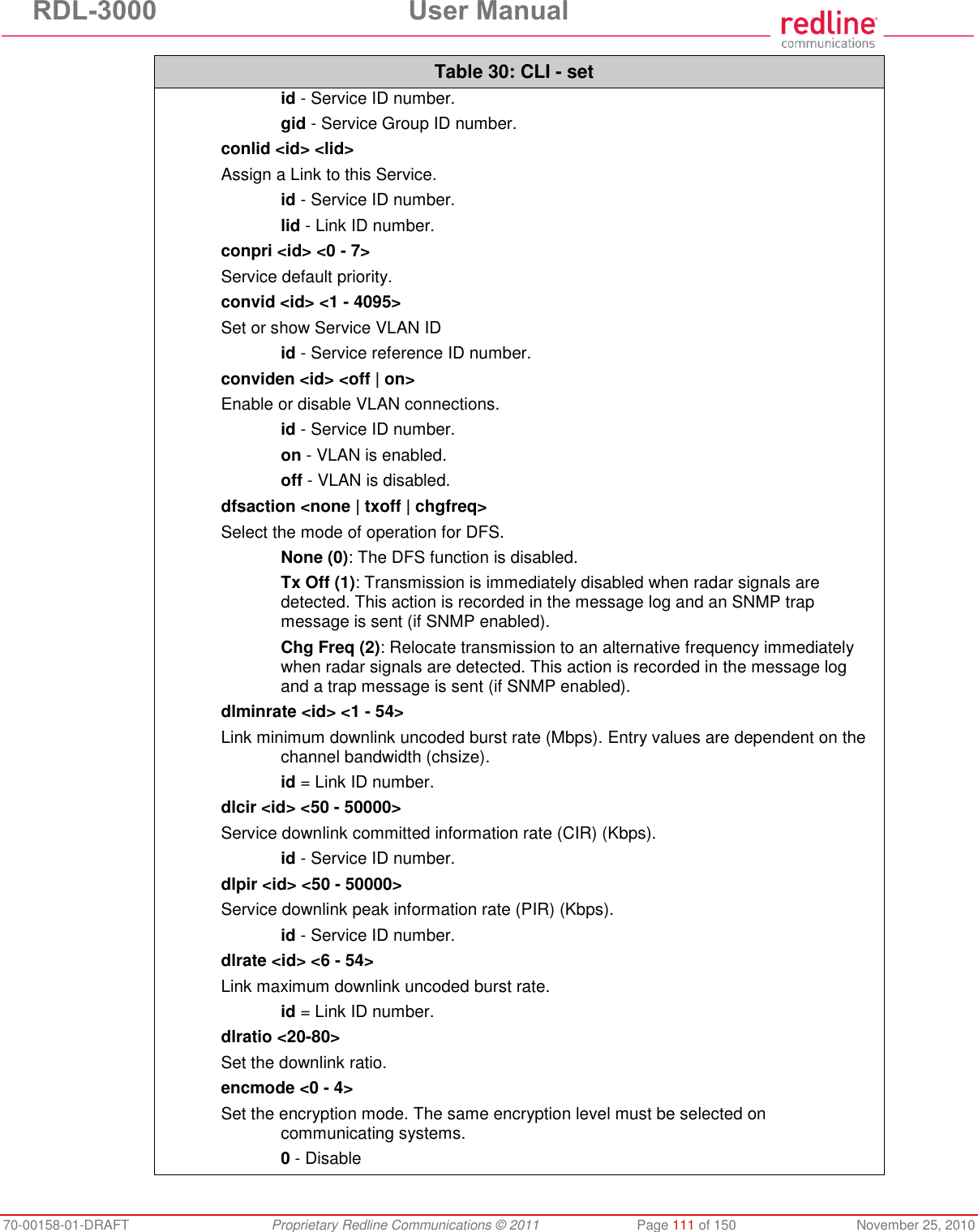
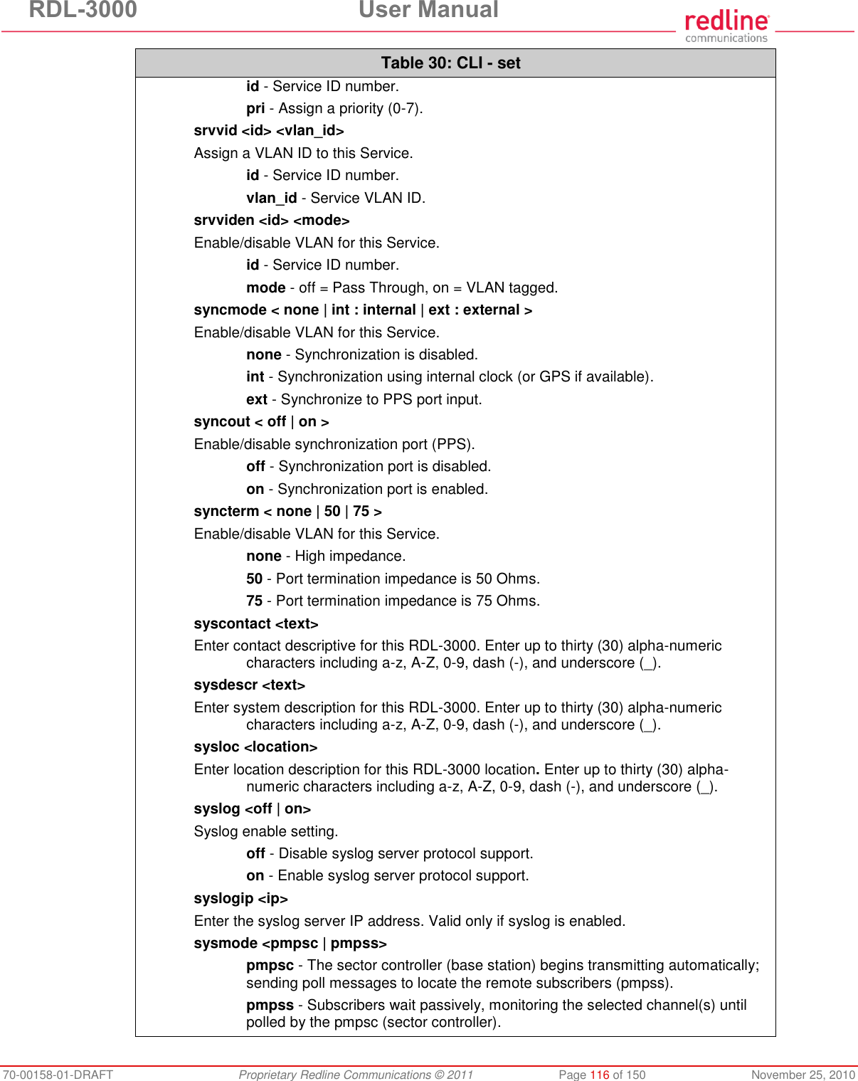
![RDL-3000 User Manual 70-00158-01-DRAFT Proprietary Redline Communications © 2011 Page 112 of 150 November 25, 2010 Table 30: CLI - set 1 - 64-bit (Redline) 2 - AES 128 3 - AES 192 4 - AES 256 ethmode <auto | 10hd | 10fd | 100 fd | 100hd> Enter a value for the combined Ethernet speed and duplex. auto - Auto-negotiate 10hd - 10Base-T Half Duplex 10fd - 10Base-T Full Duplex 100hd - 100Base-T Half Duplex 100fd - 100Base-T Full Duplex fastreg <off | on> Fast registration mode. id - Service reference ID number. fixframe <off|on> Configure the fixed frame mode. off - Use dynamic frames based on traffic patterns. on - Wireless frames are fixed at the size specified in the framesize field. framesize <size> When Fixed Frame is enabled, enter the frame size in milliseconds. size - Enter the fixed frame size (ms). gateway <ip> Enter the IP address of the default gateway on this segment. gmt <value> Enter the time offset from GMT (e.g., -5 for EST). grpcir <id> <50 - 50000> Service Group Committed Information Rate (CIR) for downlink broadcast and multicast traffic. id - Group ID number. grppir <id> <50 - 50000> Service Group peak information rate (PIR) (Kbps). Applies to uplink and downlink traffic. id - Group ID number. grprate <id> <6 - 54> Service Group maximum rate (Mbps). Applies to uplink and downlink. id - Group reference ID number. grppri <id> <pri> Service Group default priority. id - Group reference ID number. pri - Group 802.1p priority setting (0-7). grpvid <id> <vid> Display/set the value of the VLAN ID for this Service Group. id - [id number]](https://usermanual.wiki/Redline-Communications/RDL3000A/User-Guide-1577952-Page-112.png)
![RDL-3000 User Manual 70-00158-01-DRAFT Proprietary Redline Communications © 2011 Page 113 of 150 November 25, 2010 Table 30: CLI - set vid - VLAN ID grpviden <id> <off | on> Display the status or enable/disable this Service Group. id - [id number] off - Disabled on -Enabled http <off | on> Enable or disable the HTTP function. When disabled, the Web interface will not be available. off - Disable on - Enable https <off | on> Enable or disable the HTTPS function. off - Disable on - Enable idname <id> <name> View or modify the name associated with an ID. id - ID for Link, Service, or Service Group. name - Name (maximum 15 text characters). ipaddr <ip> <mask> Enter the IP address and subnet mask of the RDL-3000. Confirmation is required. Example: set ipaddr ip 192.168.100.10 mask 255.255.255.0 ldlpir <id> <50-50000> Link downlink PIR. id = Link ID number. lulpir <id> <50-50000> Link uplink PIR. id = Link ID number. maxdst <distance> Maximum distance to a subscriber. value - Distance (Km) to farthest subscriber. maxtxpower <-10 - 25> Enter the Tx power level (dBm). This setting is for the transceiver output only. The actual EIRP depends on the gain of the connected antenna. The maximum value is determined by the options key. mgmtag <off | on> Enable or disable the HTTPS function. See also mgmvid. off - Do not use VLAN to identify management traffic. on - Enable VLAN tagged management traffic. See mgmvid. mgmvid <1 - 4095> Specify Management VLAN ID. See also mgmtag. vlan_id - Management VLAN ID.](https://usermanual.wiki/Redline-Communications/RDL3000A/User-Guide-1577952-Page-113.png)
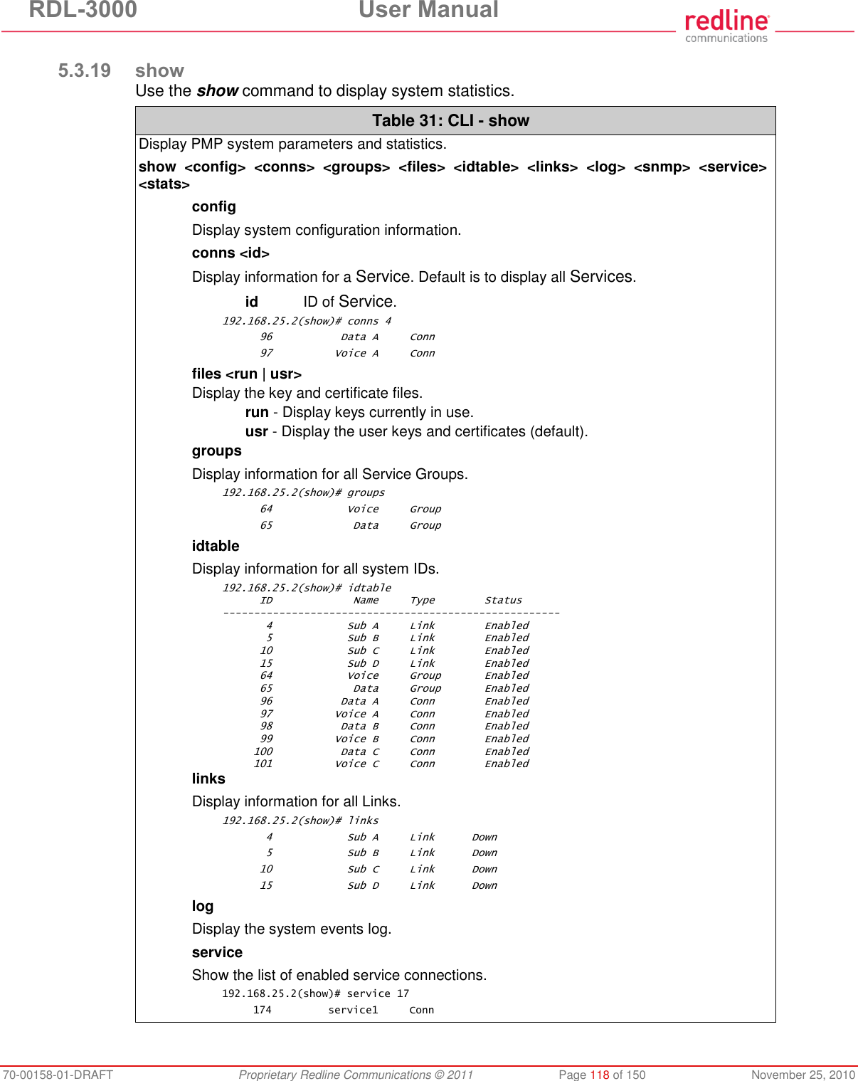
![RDL-3000 User Manual 70-00158-01-DRAFT Proprietary Redline Communications © 2011 Page 117 of 150 November 25, 2010 Table 30: CLI - set sysname <text> Enter the name for this RDL-3000. Use any combination of up to 20 letters and numbers. telnet <off | on> Enable or disable the Telnet port. If the Telnet port is disabled, it will not be possible to use the CLI interface. off - Disable on - Enable Changes to this field are effective only following reboot. telnetport <1 - 65535> Telnet port address port - Limits for the telnet port are 22..79 and 81..65534 (default is 23). Changes to this field are effective only following reboot. ulcir <id> <50-50000> Enter the uplink committed information rate for the service (Kbps). id: -[id number] ulminrate <id> <6 - 54> Link minimum downlink uncoded burst rate. id = Link ID number. ulpir <id> <50 - 50000> Service uplink peak information rate (PIR) (Kbps). id - Service ID number. ulrate <id> <1-54> Link maximum uplink uncoded burst rate. id = Link ID number. usrauthmode <local> <radius> Set the user authentication mode. Specify local services, the RADIUS server, or both in combination. local - use local authentication. radius - Use the RADIUS server. x509auth <off | on> Enable or disable authentication. off - Allow network registrations without authentication. on - Require authentication using X.509 certificates.](https://usermanual.wiki/Redline-Communications/RDL3000A/User-Guide-1577952-Page-117.png)
![RDL-3000 User Manual 70-00158-01-DRAFT Proprietary Redline Communications © 2011 Page 120 of 150 November 25, 2010 Table 33: CLI - snmptrap identity v2: Enter associated SNMP community string. v3: Enter account username for authorization. change <idx> [-p <port>] [-i <ip_add>] [-c <community>] [-u username] Modify the specified SNMP setting. idx Index of the SNMP trap (use 'print' command to display ids). -i <ip_add>] Enter destination IP address. -p <port>] Enter destination port address. -c <community> Enter associated SNMP community string (SNMP V1 or V2). -u <username> Enter account username for authorization (SNMP V3 only). clearall Delete all SNMP parameters. del <idx> Delete the specified SNMP trap. idx Index of the SNMP trap to be deleted (use 'print' command to display ids). Linkupdown Trap indicates when the wireless Link is lost and recovered. Off - On - print List all SNMP trap settings. 5.3.22 upgrade Use the upgrade command to upload a new firmware binary file to the RDL-3000. Table 34: CLI - upgrade Configure SNMP community permissions. upgrade <ip addr> <file name> <user name> <password> ip addr IP address of the FTP/TFTP server. file name Name of the binary file to be uploaded. user name FTP account name (FTP server only). password FTP account password (FTP server only). TFTP: You must specify the TFTP server address and the full name of the binary file (including .bin extension). The firmware binary file must be located in the default directory of the TFTP server. FTP: You must specify the FTP server address, account user name, account password, and the full name of the binary file (including .bin extension). The firmware binary file must be located in the default directory for the specified user account.](https://usermanual.wiki/Redline-Communications/RDL3000A/User-Guide-1577952-Page-120.png)