Redline Communications RDL3000RMC Advanced Broadband Wireless Infrastructure Solution User Manual 70 00184 03 02
Redline Communications Inc. Advanced Broadband Wireless Infrastructure Solution 70 00184 03 02
Contents
- 1. user manual
- 2. user manaul
user manual

RDL-3000 M2M Solutions
70-00184-03-02 Proprietary Redline Communications © 2013 Page 1 of 50 April 30, 2013
RDL-3000 Family
Broadband Wireless Systems
RDL-3000-RMC/E/F
Radio Modules
Product Manual
1 Product Overview ................................................................... 6
2 Conditions of Use ................................................................... 7
3 Module Installation and Service ............................................ 8
4 Final Product Requirements .................................................. 9
5 Regulatory Notices ............................................................... 41
RDL-3000 RMC/E/F MODULE PRODUCT MANUAL
70-00184-03-02 Proprietary Redline Communications © 2013 Page 2 of 50 April 30, 2013
Copyright Information
All rights reserved April 30, 2013. The information in this document is proprietary to
Redline Communications Inc. This document may not in whole or in part be copied,
reproduced, or reduced to any medium without prior consent in writing from Redline
Communications Incorporated.
Contact Information
Contact Information:
Redline Communications Inc.
302 Town Centre Blvd.
Markham, ON
Canada L3R 0E8
Web site: http://www.rdlcom.com
Email:
Inquiries: info@rdlcom.com
Support: support@rdlcom.com
Training: training@rdlcom.com
Document Control:
70-00184-03-01-RDL-3000-RMC-E-F_Module_Product_Manual-
20130430a.doc
Disclaimer
The statements, configurations, technical data, and recommendations in this document
are believed to be accurate and reliable, but are presented without express or implied
warranty. Additionally, Redline makes no representations or warranties, either expressed
or implied, regarding the contents of this product. Redline Communications shall not be
liable for any misuse regarding this product. The information in this document is subject
to change without notice. No part of this document shall be deemed to be part of any
warranty or contract unless specifically referenced to be part of such warranty or
contract within this document.

RDL-3000 RMC/E/F MODULE PRODUCT MANUAL
70-00184-03-02 Proprietary Redline Communications © 2013 Page 3 of 50 April 30, 2013
TABLE OF CONTENTS
1 Product Overview ................................................................... 6
2 Conditions of Use ................................................................... 7
2.1 General Conditions ............................................................................................ 7
2.2 Country of Use ................................................................................................... 7
2.3 Product Labeling ................................................................................................ 7
3 Module Installation and Service ............................................ 8
3.1 Installation Into a Final Product ........................................................................ 8
3.2 Module Servicing ............................................................................................... 8
3.3 Professional Installation .................................................................................... 8
3.4 Safety Precautions ............................................................................................. 8
3.5 Radio Frequency Safety .................................................................................... 8
4 Final Product Requirements .................................................. 9
4.1 RDL-3000-RMC ................................................................................................... 9
4.1.1 RDL-3000-RMC Frequency Bands .................................................................... 9
4.1.2 RDL-3000-RMC Antenna Use and Transmit Power .......................................... 9
4.1.3 RDL-3000-RMC Certified Antennas .................................................................. 9
4.1.4 RDL-3000-RMC Power & EIRP (MIMO Operation) ......................................... 10
4.9 GHz: FCC 47 CFR Part 90 Subpart Y ...................................................... 10
4.9 GHz: IC RSS-111 .................................................................................... 13
5.8 GHz: FCC 47 CFR Part 15 Subpart C, §15.247/IC RSS-210, Issue 8
Annex 8 ...................................................................................... 16
5.3 GHz: FCC 47 CFR Part 15 Subpart E, §15.407 ....................................... 19
5.3 GHz: IC RSS-210, Issue 8 Annex 9 ......................................................... 22
5.4 GHz: FCC 47 CFR Part 15 Subpart E, §15.407 ....................................... 25
5.4 GHz: FCC 47 CFR Part 15 Subpart E, §15.407 / IC RSS-210, Issue 8
Annex 9 ...................................................................................... 28
4.2 RDL-3000-RME ................................................................................................. 31
4.2.1 RDL-3000-RME Frequency Bands .................................................................. 31
4.2.2 RDL-3000-RME Antenna Use and Transmit Power ........................................ 31
4.2.3 RDL-3000-RME Certified Antennas ................................................................ 31
4.2.4 RDL-3000-RME Power & EIRP (MIMO Operation) ......................................... 32
4.3 RDL-3000-RMF ................................................................................................. 40
4.3.1 RDL-3000-RMF Frequency Bands .................................................................. 40
4.3.2 RDL-3000-RMF Antenna Use and Transmit Power ......................................... 40
4.3.3 RDL-3000-RMF Certified Antennas ................................................................. 40
5 Regulatory Notices ............................................................... 41
5.1 FCC Notices: Deployment in USA ................................................................... 41
5.1.1 RDL-3000-RMC .............................................................................................. 41

RDL-3000 RMC/E/F MODULE PRODUCT MANUAL
70-00184-03-02 Proprietary Redline Communications © 2013 Page 4 of 50 April 30, 2013
FCC Recommendations to UNII band Users ................................................. 42
5.1.2 RDL-3000-RMF ............................................................................................... 44
5.2 Industry Canada Notices: Deployment in Canada ......................................... 46
5.2.1 RDL-3000-RMC .............................................................................................. 46
5.2.2 RDL-3000-RME .............................................................................................. 48
LIST OF TABLES
Table 1: Approved Antennas ........................................................................................... 9
Table 2: 4.9 GHz: RF Power & EIRP: 5 MHz channel & 10 dBi antenna for FCC .......... 10
Table 3: 4.9 GHz: RF Power & EIRP: 5 MHz channel & 19 dBi antenna for FCC .......... 10
Table 4: 4.9 GHz: RF Power & EIRP: 5 MHz channel & 32 dBi antenna for FCC .......... 10
Table 5: 4.9 GHz: RF Power & EIRP: 10 MHz channel & 10 dBi antenna for FCC ........ 11
Table 6: 4.9 GHz: RF Power & EIRP: 10 MHz channel & 19 dBi antenna for FCC ........ 11
Table 7: 4.9 GHz: RF Power & EIRP: 10 MHz channel & 32 dBi antenna for FCC ........ 11
Table 8: 4.9 GHz: RF Power & EIRP: 20 MHz channel & 10 dBi antenna for FCC ........ 12
Table 9: 4.9 GHz: RF Power & EIRP: 20 MHz channel & 19 dBi antenna for FCC ........ 12
Table 10: 4.9 GHz: RF Power & EIRP: 20 MHz channel & 32 dBi antenna for FCC ...... 12
Table 11: 4.9 GHz: RF Power & EIRP: 5 MHz channel & 10 dBi antenna for IC ............ 13
Table 12: 4.9 GHz: RF Power & EIRP: 5 MHz channel & 19 dBi antenna for IC ............ 13
Table 13: 4.9 GHz: RF Power & EIRP: 5 MHz channel & 32 dBi antenna for IC ............ 13
Table 14: 4.9 GHz: RF Power & EIRP: 10 MHz channel & 10 dBi antenna for IC .......... 14
Table 15: 4.9 GHz: RF Power & EIRP: 10 MHz channel & 19 dBi antenna for IC .......... 14
Table 16: 4.9 GHz: RF Power & EIRP: 10 MHz channel & 32 dBi antenna for IC .......... 14
Table 17: 4.9 GHz: RF Power & EIRP: 20 MHz channel & 10 dBi antenna for IC .......... 15
Table 18: 4.9 GHz: RF Power & EIRP: 20 MHz channel & 19 dBi antenna for IC .......... 15
Table 19: 4.9 GHz: RF Power & EIRP: 20 MHz channel & 32 dBi antenna for IC .......... 15
Table 20: 5.8 GHz: RF Power & EIRP: 5 MHz channel & 10 dBi antenna for FCC/IC .... 16
Table 21: 5.8 GHz: RF Power & EIRP: 5 MHz channel & 19 dBi antenna for FCC/IC .... 16
Table 22: 5.8 GHz: RF Power & EIRP: 5 MHz channel & 32 dBi antenna for FCC/IC .... 16
Table 23: 5.8 GHz: RF Power & EIRP: 10 MHz channel & 10 dBi antenna for FCC/IC .. 17
Table 24: 5.8 GHz: RF Power & EIRP: 10 MHz channel & 19 dBi antenna for FCC/IC .. 17
Table 25: 5.8 GHz: RF Power & EIRP: 10 MHz channel & 32 dBi antenna for FCC/IC .. 17
Table 26: 5.8 GHz: RF Power & EIRP: 20 MHz channel & 10 dBi antenna for FCC/IC .. 18
Table 27: 5.8 GHz: RF Power & EIRP: 20 MHz channel & 19 dBi antenna for FCC/IC .. 18
Table 28: 5.8 GHz: RF Power & EIRP: 20 MHz channel & 32 dBi antenna for FCC/IC .. 18
Table 29: 5.3 GHz: RF Power: 5 MHz channel & 10 dBi antenna for FCC ..................... 19
Table 30: 5.3 GHz: RF Power: 5 MHz channel & 19 dBi antenna for FCC ..................... 19
Table 31: 5.3 GHz: RF Power: 5 MHz channel & 32 dBi antenna for FCC ..................... 19
Table 32: 5.3 GHz: RF Power: 10 MHz channel & 10 dBi antenna for FCC ................... 20
Table 33: 5.3 GHz: RF Power: 10 MHz channel & 19 dBi antenna for FCC ................... 20
Table 34: 5.3 GHz: RF Power: 10 MHz channel & 32 dBi antenna for FCC ................... 20
Table 35: 5.3 GHz: RF Power: 20 MHz channel & 10 dBi antenna for FCC ................... 21
Table 36: 5.3 GHz: RF Power: 20 MHz channel & 19 dBi antenna for FCC ................... 21
Table 37: 5.3 GHz: RF Power: 20 MHz channel & 32 dBi antenna for FCC ................... 21
Table 38: 5.3 GHz: RF Power & EIRP: 5 MHz channel & 10 dBi antenna for IC ............ 22
Table 39: 5.3 GHz: RF Power & EIRP: 5 MHz channel & 19 dBi antenna for IC ............ 22
Table 40: 5.3 GHz: RF Power & EIRP: 5 MHz channel & 32 dBi antenna for IC ............ 22
Table 41: 5.3 GHz: RF Power & EIRP: 10 MHz channel & 10 dBi antenna for IC .......... 23

RDL-3000 RMC/E/F MODULE PRODUCT MANUAL
70-00184-03-02 Proprietary Redline Communications © 2013 Page 5 of 50 April 30, 2013
Table 42: 5.3 GHz: RF Power & EIRP: 10 MHz channel & 19 dBi antenna for IC .......... 23
Table 43: 5.3 GHz: RF Power & EIRP: 10 MHz channel & 32 dBi antenna for IC .......... 23
Table 44: 5.3 GHz: RF Power & EIRP: 20 MHz channel & 10 dBi antenna for IC .......... 24
Table 45: 5.3 GHz: RF Power & EIRP: 20 MHz channel & 19 dBi antenna for IC .......... 24
Table 46: 5.3 GHz: RF Power & EIRP: 20 MHz channel & 32 dBi antenna for IC .......... 24
Table 47: 5.4 GHz: RF Power: 5 MHz channel & 10 dBi antenna for FCC ..................... 25
Table 48: 5.4 GHz: RF Power: 5 MHz channel & 19 dBi antenna for FCC ..................... 25
Table 49: 5.4 GHz: RF Power: 5 MHz channel & 32 dBi antenna for FCC ..................... 25
Table 50: 5.4 GHz: RF Power: 10 MHz channel & 10 dBi antenna for FCC ................... 26
Table 51: 5.4 GHz: RF Power: 10 MHz channel & 19 dBi antenna for FCC ................... 26
Table 52: 5.4 GHz: RF Power: 10 MHz channel & 32 dBi antenna for FCC ................... 26
Table 53: 5.4 GHz: RF Power: 20 MHz channel & 10 dBi antenna for FCC ................... 27
Table 54: 5.4 GHz: RF Power: 20 MHz channel & 19 dBi antenna for FCC ................... 27
Table 55: 5.4 GHz: RF Power: 20 MHz channel & 32 dBi antenna for FCC ................... 27
Table 56: 5.4 GHz: RF Power & EIRP: 5 MHz channel & 10 dBi antenna for IC ............ 28
Table 57: 5.4 GHz: RF Power & EIRP: 5 MHz channel & 19 dBi antenna for IC ............ 28
Table 58: 5.4 GHz: RF Power & EIRP: 5 MHz channel & 32 dBi antenna for IC ............ 28
Table 59: 5.4 GHz: RF Power & EIRP: 10 MHz channel & 10 dBi antenna for IC .......... 29
Table 60: 5.4 GHz: RF Power & EIRP: 10 MHz channel & 19 dBi antenna for IC .......... 29
Table 61: 5.4 GHz: RF Power & EIRP: 10 MHz channel & 32 dBi antenna for IC .......... 29
Table 62: 5.4 GHz: RF Power & EIRP: 20 MHz channel & 10 dBi antenna for IC .......... 30
Table 63: 5.4 GHz: RF Power & EIRP: 20 MHz channel & 19 dBi antenna for IC .......... 30
Table 64: 5.4 GHz: RF Power & EIRP: 20 MHz channel & 32 dBi antenna for IC .......... 30
Table 65: RDL-3000-RME: Approved Antennas ............................................................ 31
Table 66: 2.5 GHz: RF Power & EIRP: 5 MHz channel for 14.5 dBi antenna for IC ....... 32
Table 67: 2.5 GHz: RF Power & EIRP: 5 MHz channel for 15 dBi antenna for IC .......... 33
Table 68: 2.5 GHz: RF Power & EIRP: 5 MHz channel for 16 dBi antenna for IC .......... 34
Table 69: 2.5 GHz: RF Power & EIRP: 5 MHz channel for 17 dBi antenna for IC .......... 35
Table 70: 2.5 GHz: RF Power & EIRP: 10 MHz channel for 14.5 dBi antenna for IC ..... 36
Table 71: 2.5 GHz: RF Power & EIRP: 10 MHz channel for 15 dBi antenna for IC ........ 37
Table 72: 2.5 GHz: RF Power & EIRP: 10 MHz channel for 16 dBi antenna for IC ........ 38
Table 73: 2.5 GHz: RF Power & EIRP: 10 MHz channel for 17 dBi antenna for IC ........ 39
Table 74: RDL-3000-RMF: Transmit Power ................................................................... 40
Table 75: RDL-3000-RMF: Approved Antennas ............................................................ 40
Table 76: FCC: RDL-3000-RMC Recommended Safe Distances .................................. 41
Table 77: FCC: RDL-3000-RMC TDWR System Locations ........................................... 42
Table 78: FCC: RDL-3000-RME/F Recommended Safe Distances ............................... 44
Table 79: IC: RDL-3000-RMC Recommended Safe Distances ...................................... 46
Table 80: IC: RDL-3000-RMC distances de sécurité recommandées ............................ 47
Table 81: IC: RDL-3000-RME/F Recommended Safe Distances ................................... 48
Table 82: IC: RDL-3000-RME/F distances de sécurité recommandées ......................... 48

RDL-3000 RMC/E/F MODULE PRODUCT MANUAL
70-00184-03-02 Proprietary Redline Communications © 2013 Page 6 of 50 April 30, 2013
1 Product Overview
The RDL-3000-RMC, RDL-3000-RME and RDL-3000-RMF (Fixed TVBD) radio modules
are each comprised of a proprietary Media Access Control (MAC) protocol engine and
Time Division Duplexing (TDD)/ Orthogonal Frequency Division Duplexing (OFDM)
digital radio.
The RDL-3000 modules are not designed for stand-alone operation. The modules are
sold as one component of a packaged system which includes a suitable housing for the
module connectors for required external components including a power supply and
antenna system. This is afterwards referred to as the 'final product'. The final product
may be designed and manufactured by Redline or a licensed third party.
Frequency settings within the specified frequency ranges are software keyed to be
compliant with specific regulatory agency requirements in the region of deployment.
RDL-3000-RMC: 4900 to 5975 MHz
RDL-3000-RME: 2305-2320 MHz and 2345-2360 MHz
RDL-3000-RMF: 470 - 698 MHz
Important: Read this entire document prior to installing or operating these modules.

RDL-3000 RMC/E/F MODULE PRODUCT MANUAL
70-00184-03-02 Proprietary Redline Communications © 2013 Page 7 of 50 April 30, 2013
2 Conditions of Use
2.1 General Conditions
The RDL-3000-RMC/E/F modules are not provided for sale to the general public. These
modules contain a proprietary radio interface and can not be directly connected to any
standard telecommunications or computer devices. This manual is provided as
supplement to technical and operational documentation and training provided by Redline
and its agents. Any operation or use of these modules in any manner not expressly
specified within this manual or approved in writing by Redline (or its agents) is expressly
forbidden and voids the users right to operate the module. This includes, but is not
limited to, any modification of the module hardware or software, installation of the
module in a non approved enclosure, and use with non approved antennas.
2.2 Country of Use
Refer to the regulatory notices in this document before installing or operating any of
these the modules.
RDL-3000-RMC
The RDL-3000-RMC module is certified with limited modular approval for use as an
'intentional radiator' in Canada as IC: 4310A-RDL3000RMC and in the United States as
device FCC ID: QC8-RDL3000RMC.
RDL-3000-RME
The RDL-3000-RME module is certified with limited modular approval for use as an
'intentional radiator' in Canada as device:
IC: 4310A-RDL3000RME
RDL-3000-RMC
The RDL-3000-RMF module is certified with limited modular approval for use as an
'intentional radiator' in the United States as device:
FCC ID: QC8-RDL3000RMF
2.3 Product Labeling
Information labels are applied to the final product. The final product features a label on
the outside surface listing the registration number for the enclosed RDL-3000 module.
Do not to remove any labels from the module or the final product.
RDL-3000-RMC
Contains: IC: 4310A-RDL3000RMC
Contains FCC ID:QC8-RDL3000RMC
RDL-3000-RME
Contains IC: 4310A-RDL3000RME
RDL-3000-RMF
Contains FCC ID:QC8-RDL3000RMF
RDL-3000 RMC/E/F MODULE PRODUCT MANUAL
70-00184-03-02 Proprietary Redline Communications © 2013 Page 8 of 50 April 30, 2013
3 Module Installation and Service
3.1 Installation Into a Final Product
The RDL-3000-RMC/E/F modules must be installed only by trained professional
technicians authorized by Redline or its agents. The module must be installed only into
an approved enclosure (see Conditions of Use) and only at an approved manufacturing
facility or service depot.
3.2 Module Servicing
The RDL-3000-RMC/E/F modules are not intended to be field serviceable, and contains
no field serviceable or field replaceable parts. The module must be serviced only at an
approved manufacturing facility or service depot.
Warning: The RDL-3000-RMC/E/F modules are susceptible to damage from
electrostatic charge. Electrostatic Discharge (ESD) must be avoided to prevent
damaging or destroying the module. The module must always be store in an anti-static
container/bag prior to installation and following removal from the product for servicing.
Observe ESD precautions when handling the module.
3.3 Professional Installation
Devices containing the Redline RDL-3000-RMC/E/F module require professional
installation. It is the responsibility of the installer to understand the product operation
by attending training as required, reading and understanding the product
documentation, and ensuring that all building, safety and regulatory codes are met
and the installation is complete and secure.
3.4 Safety Precautions
Installation and service of RDL-3000-RMC/E/F modules must be performed by
personnel having technical training and experience necessary to be aware of hazards
during installation and/or service of RF equipment. The installation and/or service must
be done using procedures designed to minimize any danger to technical personnel or
any other person.
3.5 Radio Frequency Safety
The installer of this radio equipment must ensure that the antenna is located or pointed
such that it does not emit RF fields in excess of the general population limits as defined
by FCC CFR 47, Part 2.1091, Radio frequency radiation exposure evaluation for fixed
devices & Health Canada limits for the general population; consult Safety Code 6,
obtainable from Health Canada’s website:
http://www.hc-sc.gc.ca/ewh-semt/pubs/radiation/radio_guide-lignes_direct-eng.php .
Refer to the regulator statements included in this document.
RDL-3000 RMC/E/F MODULE PRODUCT MANUAL
70-00184-03-02 Proprietary Redline Communications © 2013 Page 9 of 50 April 30, 2013
4 Final Product Requirements
The following requirements apply to all final products incorporating an RDL-3000-RMC,
RDL-3000-RME, or RDL-3000-RMF module.
4.1 RDL-3000-RMC
4.1.1 RDL-3000-RMC Frequency Bands
Operation of the final product requires a software 'key' that is available exclusively from
Redline. This key restricts device operation to the FCC/IC 4940-4990 MHz, 5250-5350
MHz, 5470-5725 MHz, or 5725-5850 MHz band. The professional installer and operator
can not modify or otherwise circumvent these operational restrictions.
4.1.2 RDL-3000-RMC Antenna Use and Transmit Power
The RDL-3000-RMC module supports operation with 2x2 MIMO antenna systems with
two transmit chains and two receive chains. The RDL-3000-RMC module must be used
only with certified antennas and using the channel size and output power level specified
by the FCC/IC regulations.
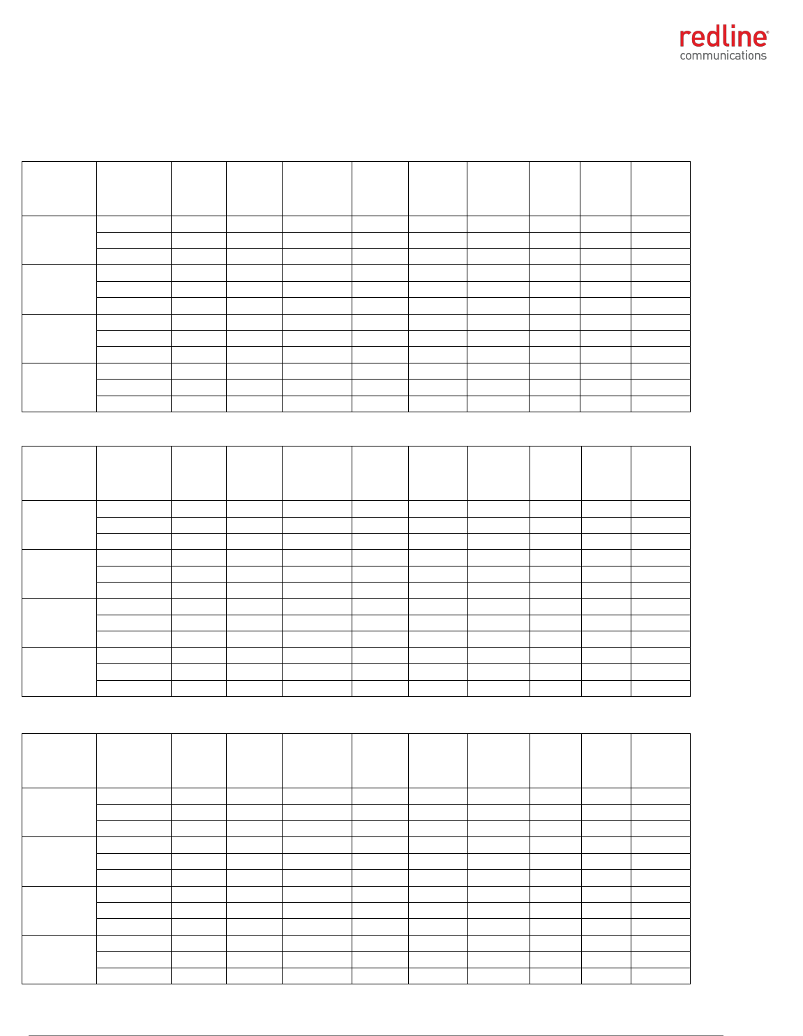
4.1.3 RDL-3000-RMC Certified Antennas
This device has been designed to operate with the antennas listed in the following table.
Any additional antennas will be used only after authorization is obtained through Class II
permissive change.
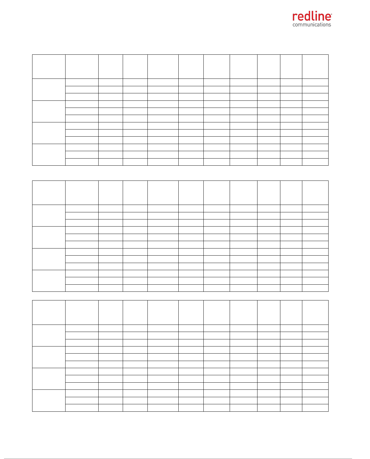
Table 1: Approved Antennas
Manufacturer
Part #
Gain (dBi)
Frequency Range
Redline
A3FT3204LTPD
32
4900-5875 MHz
Redline
30-00328-00
19
4900-5875 MHz
L-Com
HG5158DP-10U
10
5100-5800 MHz
RDL-3000 RMC/E/F MODULE PRODUCT MANUAL
70-00184-03-02 Proprietary Redline Communications © 2013 Page 10 of 50 April 30, 2013
4.1.4 RDL-3000-RMC Power & EIRP (MIMO Operation)
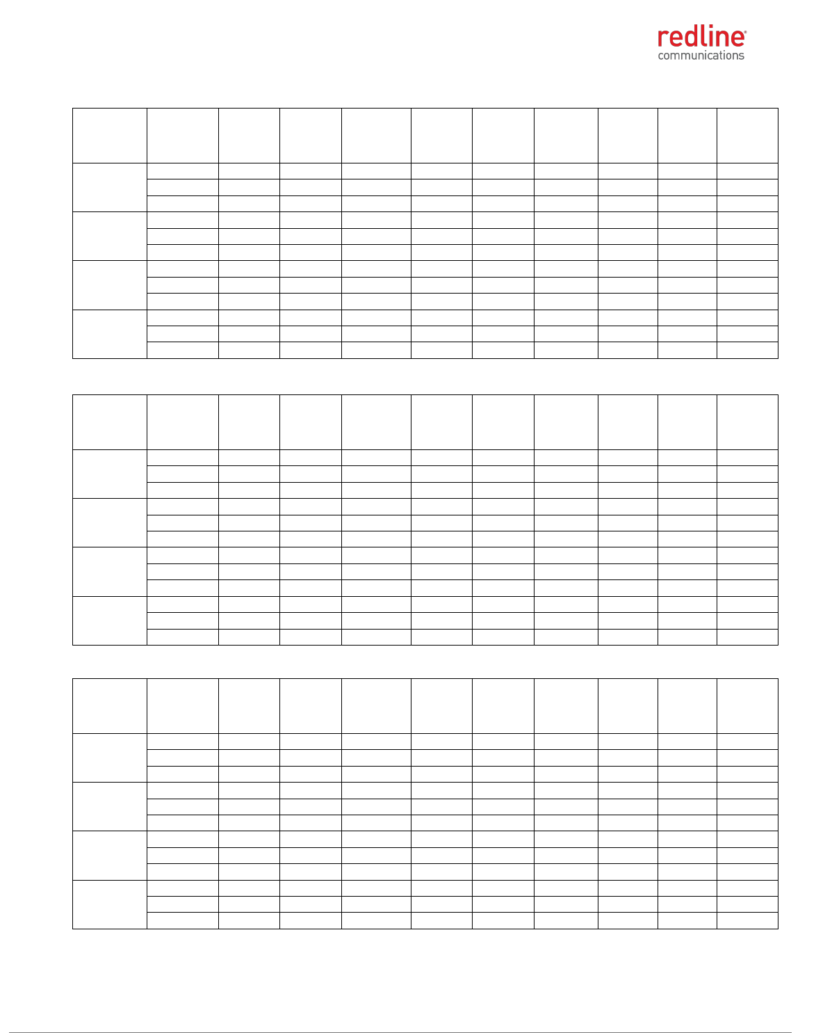
4.9 GHz: FCC 47 CFR Part 90 Subpart Y
Table 2: 4.9 GHz: RF Power & EIRP: 5 MHz channel & 10 dBi antenna for FCC
Modulation
Frequency
(MHz)
Power
at RF-1
(dBm)
Power
at RF-2
(dBm)
Combined
output
power
(dBm)
Output
power
limit
(dBm)
Power
margin,
dB
Antenna
gain
(dBi)
EIRP
(dBm)
EIRP
limit
(dBm)
EIRP
margin
(dB)
BPSK
4942.5
19.20
19.22
22.22
27.00
4.78
10.00
32.22
53.00
20.78
4965.0
19.80
19.64
22.73
27.00
4.27
10.00
32.73
53.00
20.27
4987.5
20.13
20.02
23.09
27.00
3.91
10.00
33.09
53.00
19.91
QPSK
4942.5
19.41
19.26
22.35
27.00
4.65
10.00
32.35
53.00
20.65
4965.0
19.79
19.36
22.59
27.00
4.41
10.00
32.59
53.00
20.41
4987.5
20.02
19.95
23.00
27.00
4.00
10.00
33.00
53.00
20.00
16-QAM
4942.5
19.38
19.23
22.32
27.00
4.68
10.00
32.32
53.00
20.68
4965.0
19.92
19.33
22.65
27.00
4.35
10.00
32.65
53.00
20.35
4987.5
19.99
20.11
23.06
27.00
3.94
10.00
33.06
53.00
19.94
64-QAM
4942.5
19.35
19.03
22.20
27.00
4.80
10.00
32.20
53.00
20.80
4965.0
20.03
19.53
22.80
27.00
4.20
10.00
32.80
53.00
20.20
4987.5
20.04
20.22
23.14
27.00
3.86
10.00
33.14
53.00
19.86
Table 3: 4.9 GHz: RF Power & EIRP: 5 MHz channel & 19 dBi antenna for FCC
Modulation
Frequency
(MHz)
Power
at RF-1
(dBm)
Power
at RF-2
(dBm)
Combined
output
power
(dBm)
Output
power
limit
(dBm)
Power
margin,
dB
Antenna
gain
(dBi)
EIRP
(dBm)
EIRP
limit
(dBm)
EIRP
margin
(dB)
BPSK
4942.5
19.20
19.22
22.22
27.00
4.78
19.00
41.22
53.00
11.78
4965.0
19.80
19.64
22.73
27.00
4.27
19.00
41.73
53.00
11.27
4987.5
20.13
20.02
23.09
27.00
3.91
19.00
42.09
53.00
10.91
QPSK
4942.5
19.41
19.26
22.35
27.00
4.65
19.00
41.35
53.00
11.65
4965.0
19.79
19.36
22.59
27.00
4.41
19.00
41.59
53.00
11.41
4987.5
20.02
19.95
23.00
27.00
4.00
19.00
42.00
53.00
11.00
16-QAM
4942.5
19.38
19.23
22.32
27.00
4.68
19.00
41.32
53.00
11.68
4965.0
19.92
19.33
22.65
27.00
4.35
19.00
41.65
53.00
11.35
4987.5
19.99
20.11
23.06
27.00
3.94
19.00
42.06
53.00
10.94
64-QAM
4942.5
19.35
19.03
22.20
27.00
4.80
19.00
41.20
53.00
11.80
4965.0
20.03
19.53
22.80
27.00
4.20
19.00
41.80
53.00
11.20
4987.5
20.04
20.22
23.14
27.00
3.86
19.00
42.14
53.00
10.86
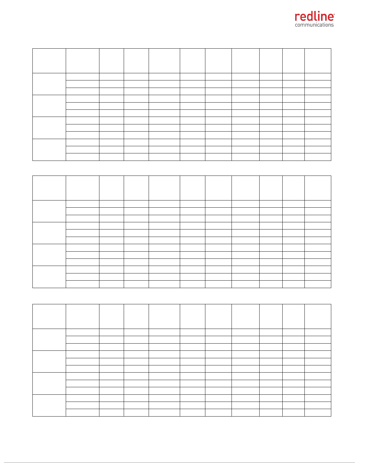
Table 4: 4.9 GHz: RF Power & EIRP: 5 MHz channel & 32 dBi antenna for FCC
Modulation
Frequency
(MHz)
Power
at RF-1
(dBm)
Power
at RF-2
(dBm)
Combined
output
power
(dBm)
Output
power
limit
(dBm)
Power
margin,
dB
Antenna
gain
(dBi)
EIRP
(dBm)
EIRP
limit
(dBm)
EIRP
margin
(dB)
BPSK
4942.5
17.73
18.14
20.95
21.00
0.05
32.00
52.95
53.00
0.05
4965.0
17.27
17.82
20.56
21.00
0.44
32.00
52.56
53.00
0.44
4987.5
17.48
17.88
20.69
21.00
0.31
32.00
52.69
53.00
0.31
QPSK
4942.5
17.59
17.75
20.68
21.00
0.32
32.00
52.68
53.00
0.32
4965.0
17.37
17.79
20.60
21.00
0.40
32.00
52.60
53.00
0.40
4987.5
17.52
17.87
20.71
21.00
0.29
32.00
52.71
53.00
0.29
16-QAM
4942.5
17.74
17.70
20.73
21.00
0.27
32.00
52.73
53.00
0.27
4965.0
17.35
17.76
20.57
21.00
0.43
32.00
52.57
53.00
0.43
4987.5
17.19
17.90
20.57
21.00
0.43
32.00
52.57
53.00
0.43
64-QAM
4942.5
17.82
17.70
20.77
21.00
0.23
32.00
52.77
53.00
0.23
4965.0
17.22
17.85
20.56
21.00
0.44
32.00
52.56
53.00
0.44
4987.5
17.17
17.98
20.60
21.00
0.40
32.00
52.60
53.00
0.40
RDL-3000 RMC/E/F MODULE PRODUCT MANUAL
70-00184-03-02 Proprietary Redline Communications © 2013 Page 11 of 50 April 30, 2013
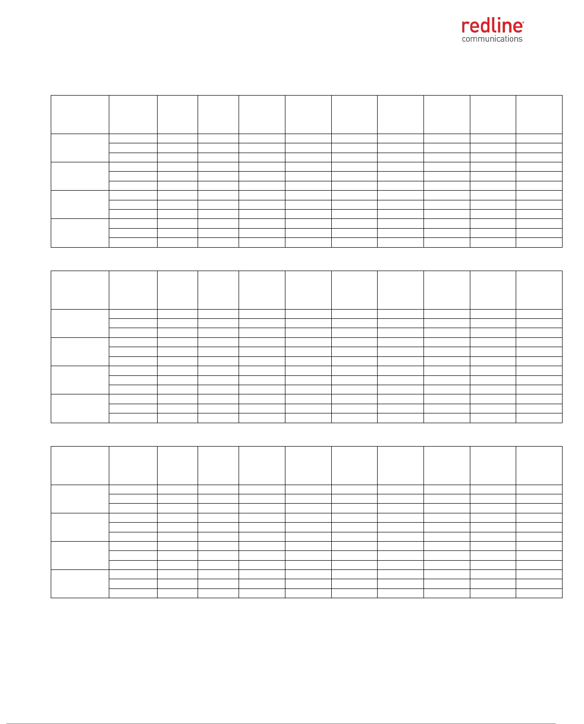
Table 5: 4.9 GHz: RF Power & EIRP: 10 MHz channel & 10 dBi antenna for FCC
Modulation
Frequency
(MHz)
Power
at RF-1
(dBm)
Power
at RF-2
(dBm)
Combined
output
power
(dBm)
Output
power
limit
(dBm)
Power
margin,
dB
Antenna
gain
(dBi)
EIRP
(dBm)
EIRP
limit
(dBm)
EIRP
margin
(dB)
BPSK
4945.0
19.73
19.13
22.45
30.00
7.55
10.00
32.45
56.00
23.55
4965.0
20.01
19.59
22.82
30.00
7.18
10.00
32.82
56.00
23.18
4985.0
20.33
20.13
23.24
30.00
6.76
10.00
33.24
56.00
22.76
QPSK
4945.0
19.58
19.08
22.35
30.00
7.65
10.00
32.35
56.00
23.65
4965.0
19.81
19.87
22.85
30.00
7.15
10.00
32.85
56.00
23.15
4985.0
20.41
19.99
23.22
30.00
6.78
10.00
33.22
56.00
22.78
16-QAM
4945.0
19.63
19.08
22.37
30.00
7.63
10.00
32.37
56.00
23.63
4965.0
19.82
19.90
22.87
30.00
7.13
10.00
32.87
56.00
23.13
4985.0
20.19
20.00
23.11
30.00
6.89
10.00
33.11
56.00
22.89
64-QAM
4945.0
19.81
19.09
22.48
30.00
7.52
10.00
32.48
56.00
23.52
4965.0
19.81
19.94
22.89
30.00
7.11
10.00
32.89
56.00
23.11
4985.0
20.34
20.00
23.18
30.00
6.82
10.00
33.18
56.00
22.82
Table 6: 4.9 GHz: RF Power & EIRP: 10 MHz channel & 19 dBi antenna for FCC
Modulation
Frequency
(MHz)
Power
at RF-1
(dBm)
Power
at RF-2
(dBm)
Combined
output
power
(dBm)
Output
power
limit
(dBm)
Power
margin,
dB
Antenna
gain
(dBi)
EIRP
(dBm)
EIRP
limit
(dBm)
EIRP
margin
(dB)
BPSK
4945.0
19.73
19.13
22.45
30.00
7.55
19.00
41.45
56.00
14.55
4965.0
20.01
19.59
22.82
30.00
7.18
19.00
41.82
56.00
14.18
4985.0
20.33
20.13
23.24
30.00
6.76
19.00
42.24
56.00
13.76
QPSK
4945.0
19.58
19.08
22.35
30.00
7.65
19.00
41.35
56.00
14.65
4965.0
19.81
19.87
22.85
30.00
7.15
19.00
41.85
56.00
14.15
4985.0
20.41
19.99
23.22
30.00
6.78
19.00
42.22
56.00
13.78
16-QAM
4945.0
19.63
19.08
22.37
30.00
7.63
19.00
41.37
56.00
14.63
4965.0
19.82
19.90
22.87
30.00
7.13
19.00
41.87
56.00
14.13
4985.0
20.19
20.00
23.11
30.00
6.89
19.00
42.11
56.00
13.89
64-QAM
4945.0
19.81
19.09
22.48
30.00
7.52
19.00
41.48
56.00
14.52
4965.0
19.81
19.94
22.89
30.00
7.11
19.00
41.89
56.00
14.11
4985.0
20.34
20.00
23.18
30.00
6.82
19.00
42.18
56.00
13.82
Table 7: 4.9 GHz: RF Power & EIRP: 10 MHz channel & 32 dBi antenna for FCC
Modulation
Frequency
(MHz)
Power
at RF-1
(dBm)
Power
at RF-2
(dBm)
Combined
output
power
(dBm)
Output
power
limit
(dBm)
Power
margin,
dB
Antenna
gain
(dBi)
EIRP
(dBm)
EIRP
limit
(dBm)
EIRP
margin
(dB)
BPSK
4945.0
19.73
19.13
22.45
24.00
1.55
32.00
54.45
56.00
1.55
4965.0
20.01
19.59
22.82
24.00
1.18
32.00
54.82
56.00
1.18
4985.0
20.33
20.13
23.24
24.00
0.76
32.00
55.24
56.00
0.76
QPSK
4945.0
19.58
19.08
22.35
24.00
1.65
32.00
54.35
56.00
1.65
4965.0
19.81
19.87
22.85
24.00
1.15
32.00
54.85
56.00
1.15
4985.0
20.41
19.99
23.22
24.00
0.78
32.00
55.22
56.00
0.78
16-QAM
4945.0
19.63
19.08
22.37
24.00
1.63
32.00
54.37
56.00
1.63
4965.0
19.82
19.90
22.87
24.00
1.13
32.00
54.87
56.00
1.13
4985.0
20.19
20.00
23.11
24.00
0.89
32.00
55.11
56.00
0.89
64-QAM
4945.0
19.81
19.09
22.48
24.00
1.52
32.00
54.48
56.00
1.52
4965.0
19.81
19.94
22.89
24.00
1.11
32.00
54.89
56.00
1.11
4985.0
20.34
20.00
23.18
24.00
0.82
32.00
55.18
56.00
0.82
RDL-3000 RMC/E/F MODULE PRODUCT MANUAL
70-00184-03-02 Proprietary Redline Communications © 2013 Page 12 of 50 April 30, 2013
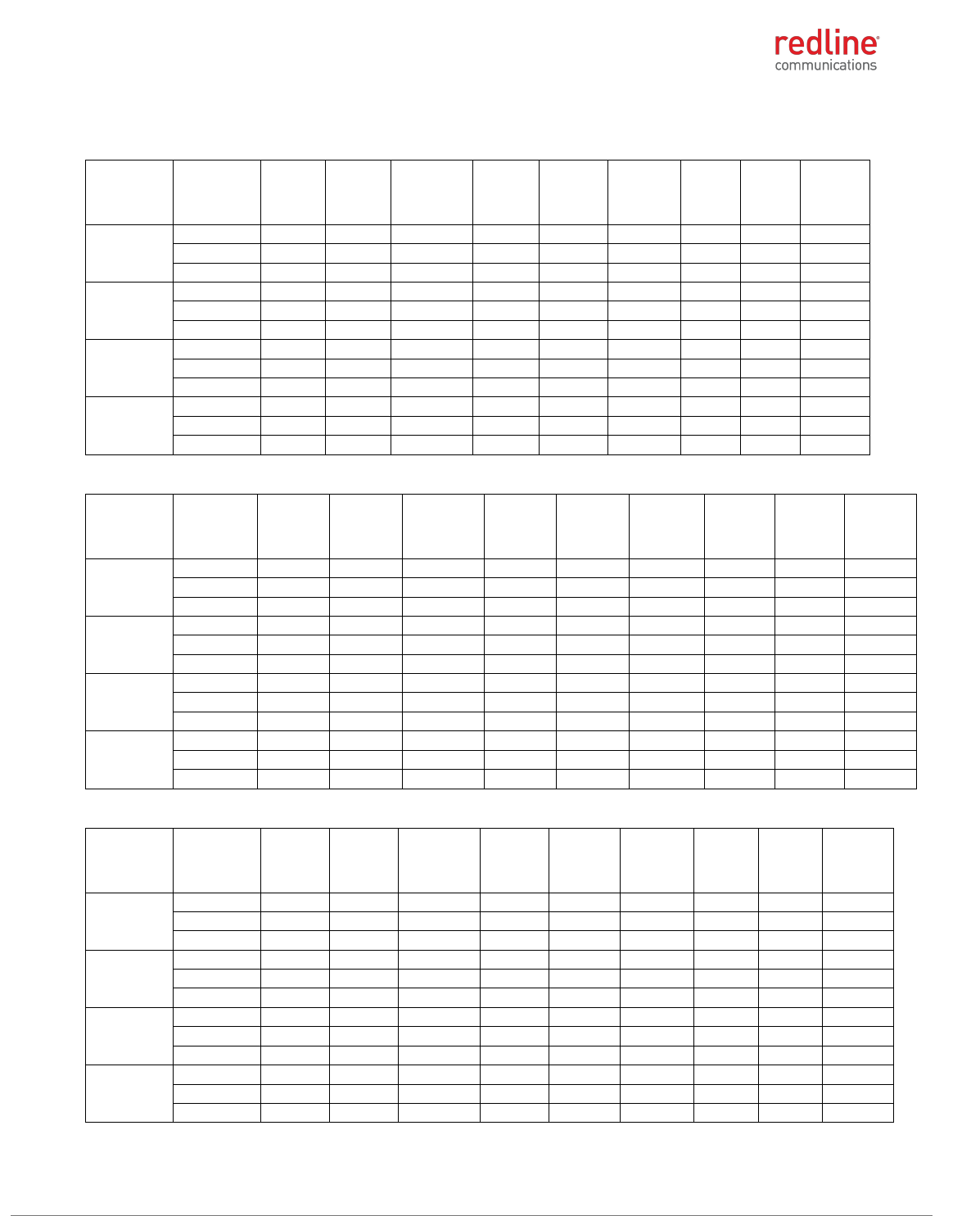
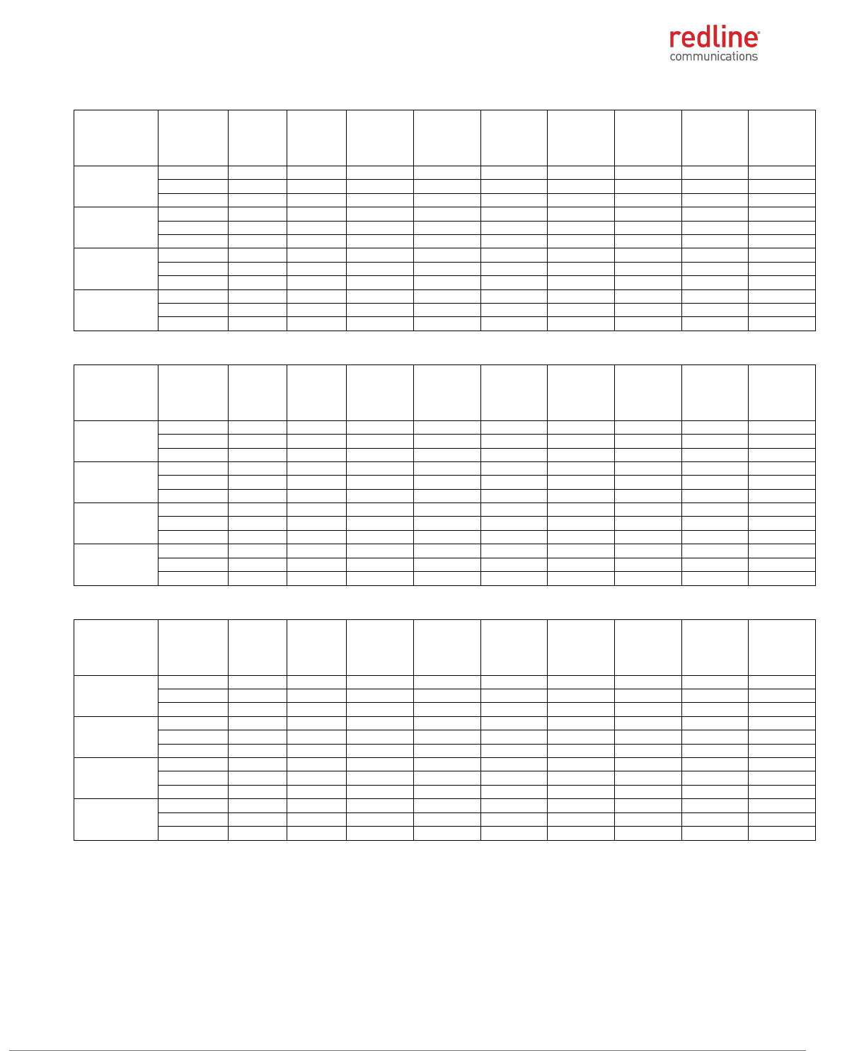
Table 8: 4.9 GHz: RF Power & EIRP: 20 MHz channel & 10 dBi antenna for FCC
Modulation
Frequency
(MHz)
Power
at RF-1
(dBm)
Power
at RF-2
(dBm)
Combined
output
power
(dBm)
Output
power
limit
(dBm)
Power
margin,
dB
Antenna
gain
(dBi)
EIRP
(dBm)
EIRP
limit
(dBm)
EIRP
margin
(dB)
BPSK
4950.0
20.57
20.00
23.30
33.00
9.70
10.00
33.30
59.00
25.70
4965.0
20.80
20.45
23.64
33.00
9.36
10.00
33.64
59.00
25.36
4980.0
21.13
20.76
23.96
33.00
9.04
10.00
33.96
59.00
25.04
QPSK
4950.0
20.57
19.98
23.30
33.00
9.70
10.00
33.30
59.00
25.70
4965.0
20.83
20.53
23.69
33.00
9.31
10.00
33.69
59.00
25.31
4980.0
21.09
20.75
23.93
33.00
9.07
10.00
33.93
59.00
25.07
16-QAM
4950.0
20.52
20.26
23.40
33.00
9.60
10.00
33.40
59.00
25.60
4965.0
20.89
20.53
23.72
33.00
9.28
10.00
33.72
59.00
25.28
4980.0
21.03
20.77
23.91
33.00
9.09
10.00
33.91
59.00
25.09
64-QAM
4950.0
20.51
20.32
23.43
33.00
9.57
10.00
33.43
59.00
25.57
4965.0
20.93
20.52
23.74
33.00
9.26
10.00
33.74
59.00
25.26
4980.0
21.08
21.14
24.12
33.00
8.88
10.00
34.12
59.00
24.88
Table 9: 4.9 GHz: RF Power & EIRP: 20 MHz channel & 19 dBi antenna for FCC
Modulation
Frequency
(MHz)
Power
at RF-1
(dBm)
Power
at RF-2
(dBm)
Combined
output
power
(dBm)
Output
power
limit
(dBm)
Power
margin,
dB
Antenna
gain
(dBi)
EIRP
(dBm)
EIRP
limit
(dBm)
EIRP
margin
(dB)
BPSK
4950.0
20.57
20.00
23.30
33.00
9.70
19.00
42.30
59.00
16.70
4965.0
20.80
20.45
23.64
33.00
9.36
19.00
42.64
59.00
16.36
4980.0
21.13
20.76
23.96
33.00
9.04
19.00
42.96
59.00
16.04
QPSK
4950.0
20.57
19.98
23.30
33.00
9.70
19.00
42.30
59.00
16.70
4965.0
20.83
20.53
23.69
33.00
9.31
19.00
42.69
59.00
16.31
4980.0
21.09
20.75
23.93
33.00
9.07
19.00
42.93
59.00
16.07
16-QAM
4950.0
20.52
20.26
23.40
33.00
9.60
19.00
42.40
59.00
16.60
4965.0
20.89
20.53
23.72
33.00
9.28
19.00
42.72
59.00
16.28
4980.0
21.03
20.77
23.91
33.00
9.09
19.00
42.91
59.00
16.09
64-QAM
4950.0
20.51
20.32
23.43
33.00
9.57
19.00
42.43
59.00
16.57
4965.0
20.93
20.52
23.74
33.00
9.26
19.00
42.74
59.00
16.26
4980.0
21.08
21.14
24.12
33.00
8.88
19.00
43.12
59.00
15.88
T
Table 10: 4.9 GHz: RF Power & EIRP: 20 MHz channel & 32 dBi antenna for FCC
Modulation
Frequency
(MHz)
Power
at RF-1
(dBm)
Power
at RF-2
(dBm)
Combined
output
power
(dBm)
Output
power
limit
(dBm)
Power
margin,
dB
Antenna
gain
(dBi)
EIRP
(dBm)
EIRP
limit
(dBm)
EIRP
margin
(dB)
BPSK
4950.0
20.57
20.00
23.30
27.00
3.70
32.00
55.30
59.00
3.70
4965.0
20.80
20.45
23.64
27.00
3.36
32.00
55.64
59.00
3.36
4980.0
21.13
20.76
23.96
27.00
3.04
32.00
55.96
59.00
3.04
QPSK
4950.0
20.57
19.98
23.30
27.00
3.70
32.00
55.30
59.00
3.70
4965.0
20.83
20.53
23.69
27.00
3.31
32.00
55.69
59.00
3.31
4980.0
21.09
20.75
23.93
27.00
3.07
32.00
55.93
59.00
3.07
16-QAM
4950.0
20.52
20.26
23.40
27.00
3.60
32.00
55.40
59.00
3.60
4965.0
20.89
20.53
23.72
27.00
3.28
32.00
55.72
59.00
3.28
4980.0
21.03
20.77
23.91
27.00
3.09
32.00
55.91
59.00
3.09
64-QAM
4950.0
20.51
20.32
23.43
27.00
3.57
32.00
55.43
59.00
3.57
4965.0
20.93
20.52
23.74
27.00
3.26
32.00
55.74
59.00
3.26
4980.0
21.08
21.14
24.12
27.00
2.88
32.00
56.12
59.00
2.88
RDL-3000 RMC/E/F MODULE PRODUCT MANUAL
70-00184-03-02 Proprietary Redline Communications © 2013 Page 13 of 50 April 30, 2013
4.9 GHz: IC RSS-111
Table 11: 4.9 GHz: RF Power & EIRP: 5 MHz channel & 10 dBi antenna for IC
Modulation
Frequency
(MHz)
Power
at RF-1
(dBm)
Power
at RF-2
(dBm)
Combined
output
power
(dBm)
Output
power
limit
(dBm)
Power
margin,
dB
Antenna
gain
(dBi)
EIRP
(dBm)
EIRP
limit
(dBm)
EIRP
margin
(dB)
BPSK
4942.5
22.81
23.63
26.25
27.00
0.75
10.00
36.25
53.00
16.75
4965.0
22.77
22.75
25.77
27.00
1.23
10.00
35.77
53.00
17.23
4987.5
23.16
22.94
26.06
27.00
0.94
10.00
36.06
53.00
16.94
QPSK
4942.5
22.63
23.64
26.17
27.00
0.83
10.00
36.17
53.00
16.83
4965.0
22.84
22.96
25.91
27.00
1.09
10.00
35.91
53.00
17.09
4987.5
23.22
23.51
26.38
27.00
0.62
10.00
36.38
53.00
16.62
16-QAM
4942.5
22.78
23.81
26.34
27.00
0.66
10.00
36.34
53.00
16.66
4965.0
23.19
23.07
26.14
27.00
0.86
10.00
36.14
53.00
16.86
4987.5
23.17
22.81
26.00
27.00
1.00
10.00
36.00
53.00
17.00
64-QAM
4942.5
22.54
23.78
26.21
27.00
0.79
10.00
36.21
53.00
16.79
4965.0
23.40
22.72
26.08
27.00
0.92
10.00
36.08
53.00
16.92
4987.5
23.31
23.10
26.22
27.00
0.78
10.00
36.22
53.00
16.78
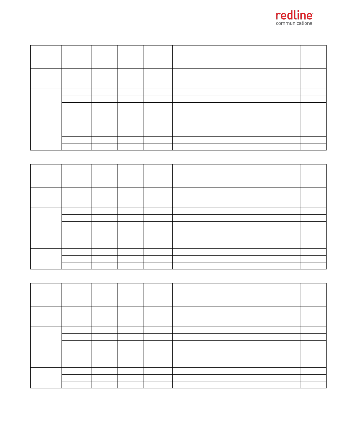
Table 12: 4.9 GHz: RF Power & EIRP: 5 MHz channel & 19 dBi antenna for IC
Modulation
Frequency
(MHz)
Power at
RF-1
(dBm)
Power at
RF-2
(dBm)
Combined
output
power
(dBm)
Output
power
limit
(dBm)
Power
margin,
dB
Antenna
gain
(dBi)
EIRP
(dBm)
EIRP
limit
(dBm)
EIRP
margin
(dB)
BPSK
4942.5
22.81
23.63
26.25
27.00
0.75
19.00
45.25
53.00
7.75
4965.0
22.77
22.75
25.77
27.00
1.23
19.00
44.77
53.00
8.23
4987.5
23.16
22.94
26.06
27.00
0.94
19.00
45.06
53.00
7.94
QPSK
4942.5
22.63
23.64
26.17
27.00
0.83
19.00
45.17
53.00
7.83
4965.0
22.84
22.96
25.91
27.00
1.09
19.00
44.91
53.00
8.09
4987.5
23.22
23.51
26.38
27.00
0.62
19.00
45.38
53.00
7.62
16-QAM
4942.5
22.78
23.81
26.34
27.00
0.66
19.00
45.34
53.00
7.66
4965.0
23.19
23.07
26.14
27.00
0.86
19.00
45.14
53.00
7.86
4987.5
23.17
22.81
26.00
27.00
1.00
19.00
45.00
53.00
8.00
64-QAM
4942.5
22.54
23.78
26.21
27.00
0.79
19.00
45.21
53.00
7.79
4965.0
23.40
22.72
26.08
27.00
0.92
19.00
45.08
53.00
7.92
4987.5
23.31
23.10
26.22
27.00
0.78
19.00
45.22
53.00
7.78
Table 13: 4.9 GHz: RF Power & EIRP: 5 MHz channel & 32 dBi antenna for IC
Modulation
Frequency
(MHz)
Power
at RF-1
(dBm)
Power
at RF-2
(dBm)
Combined
output
power
(dBm)
Output
power
limit
(dBm)
Power
margin,
dB
Antenna
gain
(dBi)
EIRP
(dBm)
EIRP
limit
(dBm)
EIRP
margin
(dB)
BPSK
4942.5
16.90
16.89
19.91
21.00
1.09
32.00
51.91
53.00
1.09
4965.0
16.94
16.51
19.74
21.00
1.26
32.00
51.74
53.00
1.26
4987.5
17.35
17.19
20.28
21.00
0.72
32.00
52.28
53.00
0.72
QPSK
4942.5
17.12
16.98
20.06
21.00
0.94
32.00
52.06
53.00
0.94
4965.0
17.04
16.50
19.79
21.00
1.21
32.00
51.79
53.00
1.21
4987.5
17.33
17.12
20.24
21.00
0.76
32.00
52.24
53.00
0.76
16-QAM
4942.5
17.00
16.34
19.69
21.00
1.31
32.00
51.69
53.00
1.31
4965.0
16.73
16.65
19.70
21.00
1.30
32.00
51.70
53.00
1.30
4987.5
17.54
17.24
20.40
21.00
0.60
32.00
52.40
53.00
0.60
64-QAM
4942.5
16.57
16.38
19.49
21.00
1.51
32.00
51.49
53.00
1.51
4965.0
16.64
16.81
19.74
21.00
1.26
32.00
51.74
53.00
1.26
4987.5
17.44
17.08
20.27
21.00
0.73
32.00
52.27
53.00
0.73
RDL-3000 RMC/E/F MODULE PRODUCT MANUAL
70-00184-03-02 Proprietary Redline Communications © 2013 Page 14 of 50 April 30, 2013
Table 14: 4.9 GHz: RF Power & EIRP: 10 MHz channel & 10 dBi antenna for IC
Modulation
Frequency
(MHz)
Power at
RF-1
(dBm)
Power at
RF-2
(dBm)
Combined
output
power
(dBm)
Output
power
limit
(dBm)
Power
margin,
dB
Antenna
gain
(dBi)
EIRP
(dBm)
EIRP
limit
(dBm)
EIRP
margin
(dB)
BPSK
4945.0
26.37
25.87
29.14
30.00
0.86
10.00
39.14
56.00
16.86
4965.0
26.39
26.38
29.40
30.00
0.60
10.00
39.40
56.00
16.60
4985.0
25.62
26.20
28.93
30.00
1.07
10.00
38.93
56.00
17.07
QPSK
4945.0
26.32
26.03
29.19
30.00
0.81
10.00
39.19
56.00
16.81
4965.0
26.41
26.27
29.35
30.00
0.65
10.00
39.35
56.00
16.65
4985.0
25.51
26.27
28.92
30.00
1.08
10.00
38.92
56.00
17.08
16-QAM
4945.0
26.19
25.81
29.01
30.00
0.99
10.00
39.01
56.00
16.99
4965.0
26.40
26.23
29.33
30.00
0.67
10.00
39.33
56.00
16.67
4985.0
25.68
26.24
28.98
30.00
1.02
10.00
38.98
56.00
17.02
64-QAM
4945.0
26.27
26.19
29.24
30.00
0.76
10.00
39.24
56.00
16.76
4965.0
26.49
26.27
29.39
30.00
0.61
10.00
39.39
56.00
16.61
4985.0
25.78
26.35
29.08
30.00
0.92
10.00
39.08
56.00
16.92
Table 15: 4.9 GHz: RF Power & EIRP: 10 MHz channel & 19 dBi antenna for IC
Modulation
Frequency
(MHz)
Power at
RF-1
(dBm)
Power at
RF-2
(dBm)
Combined
output
power
(dBm)
Output
power
limit
(dBm)
Power
margin,
dB
Antenna
gain
(dBi)
EIRP
(dBm)
EIRP
limit
(dBm)
EIRP
margin
(dB)
BPSK
4945.0
26.37
25.87
29.14
30.00
0.86
19.00
48.14
56.00
7.86
4965.0
26.39
26.38
29.40
30.00
0.60
19.00
48.40
56.00
7.60
4985.0
26.93
27.01
29.98
30.00
0.02
19.00
48.98
56.00
7.02
QPSK
4945.0
26.32
26.03
29.19
30.00
0.81
19.00
48.19
56.00
7.81
4965.0
26.41
26.27
29.35
30.00
0.65
19.00
48.35
56.00
7.65
4985.0
25.51
26.87
29.25
30.00
0.75
19.00
48.25
56.00
7.75
16-QAM
4945.0
26.19
25.81
29.01
30.00
0.99
19.00
48.01
56.00
7.99
4965.0
26.40
26.23
29.33
30.00
0.67
19.00
48.33
56.00
7.67
4985.0
25.68
26.95
29.37
30.00
0.63
19.00
48.37
56.00
7.63
64-QAM
4945.0
26.27
26.19
29.24
30.00
0.76
19.00
48.24
56.00
7.76
4965.0
26.49
26.27
29.39
30.00
0.61
19.00
48.39
56.00
7.61
4985.0
25.78
26.35
29.08
30.00
0.92
19.00
48.08
56.00
7.92
Table 16: 4.9 GHz: RF Power & EIRP: 10 MHz channel & 32 dBi antenna for IC
Modulation
Frequency
(MHz)
Power at
RF-1
(dBm)
Power at
RF-2
(dBm)
Combined
output
power
(dBm)
Output
power
limit
(dBm)
Power
margin,
dB
Antenna
gain
(dBi)
EIRP
(dBm)
EIRP
limit
(dBm)
EIRP
margin
(dB)
BPSK
4945.0
20.82
20.54
23.69
24.00
0.31
32.00
55.69
56.00
0.31
4965.0
19.79
20.52
23.18
24.00
0.82
32.00
55.18
56.00
0.82
4985.0
20.32
20.21
23.28
24.00
0.72
32.00
55.28
56.00
0.72
QPSK
4945.0
20.59
20.48
23.55
24.00
0.45
32.00
55.55
56.00
0.45
4965.0
19.79
20.84
23.36
24.00
0.64
32.00
55.36
56.00
0.64
4985.0
20.05
20.33
23.20
24.00
0.80
32.00
55.20
56.00
0.80
16-QAM
4945.0
20.41
20.21
23.32
24.00
0.68
32.00
55.32
56.00
0.68
4965.0
19.68
20.53
23.14
24.00
0.86
32.00
55.14
56.00
0.86
4985.0
20.17
20.27
23.23
24.00
0.77
32.00
55.23
56.00
0.77
64-QAM
4945.0
20.37
20.29
23.34
24.00
0.66
32.00
55.34
56.00
0.66
4965.0
19.80
20.82
23.35
24.00
0.65
32.00
55.35
56.00
0.65
4985.0
20.20
20.25
23.24
24.00
0.76
32.00
55.24
56.00
0.76
RDL-3000 RMC/E/F MODULE PRODUCT MANUAL
70-00184-03-02 Proprietary Redline Communications © 2013 Page 15 of 50 April 30, 2013
Table 17: 4.9 GHz: RF Power & EIRP: 20 MHz channel & 10 dBi antenna for IC
Modulation
Frequency
(MHz)
Power at
RF-1
(dBm)
Power at
RF-2
(dBm)
Combined
output
power
(dBm)
Output
power
limit
(dBm)
Power
margin,
dB
Antenna
gain
(dBi)
EIRP
(dBm)
EIRP
limit
(dBm)
EIRP
margin
(dB)
BPSK
4950.0
27.41
27.64
30.54
33.00
2.46
10.00
40.54
59.00
18.46
4965.0
27.91
27.99
30.96
33.00
2.04
10.00
40.96
59.00
18.04
4980.0
27.90
27.84
30.88
33.00
2.12
10.00
40.88
59.00
18.12
QPSK
4950.0
27.18
27.50
30.35
33.00
2.65
10.00
40.35
59.00
18.65
4965.0
27.64
27.57
30.62
33.00
2.38
10.00
40.62
59.00
18.38
4980.0
28.16
28.32
31.25
33.00
1.75
10.00
41.25
59.00
17.75
16-QAM
4950.0
27.26
27.69
30.49
33.00
2.51
10.00
40.49
59.00
18.51
4965.0
27.67
27.63
30.66
33.00
2.34
10.00
40.66
59.00
18.34
4980.0
28.18
28.08
31.14
33.00
1.86
10.00
41.14
59.00
17.86
64-QAM
4950.0
28.04
28.12
31.09
33.00
1.91
10.00
41.09
59.00
17.91
4965.0
28.12
28.10
31.12
33.00
1.88
10.00
41.12
59.00
17.88
4980.0
28.07
27.99
31.04
33.00
1.96
10.00
41.04
59.00
17.96
Table 18: 4.9 GHz: RF Power & EIRP: 20 MHz channel & 19 dBi antenna for IC
Modulation
Frequency
(MHz)
Power at
RF-1
(dBm)
Power at
RF-2
(dBm)
Combined
output
power
(dBm)
Output
power
limit
(dBm)
Power
margin,
dB
Antenna
gain
(dBi)
EIRP
(dBm)
EIRP
limit
(dBm)
EIRP
margin
(dB)
BPSK
4950.0
27.41
27.64
30.54
33.00
2.46
19.00
49.54
59.00
9.46
4965.0
27.91
27.99
30.96
33.00
2.04
19.00
49.96
59.00
9.04
4980.0
27.90
27.84
30.88
33.00
2.12
19.00
49.88
59.00
9.12
QPSK
4950.0
27.18
27.50
30.35
33.00
2.65
19.00
49.35
59.00
9.65
4965.0
27.64
27.57
30.62
33.00
2.38
19.00
49.62
59.00
9.38
4980.0
28.16
28.32
31.25
33.00
1.75
19.00
50.25
59.00
8.75
16-QAM
4950.0
27.26
27.69
30.49
33.00
2.51
19.00
49.49
59.00
9.51
4965.0
27.67
27.63
30.66
33.00
2.34
19.00
49.66
59.00
9.34
4980.0
28.18
28.08
31.14
33.00
1.86
19.00
50.14
59.00
8.86
64-QAM
4950.0
28.04
28.12
31.09
33.00
1.91
19.00
50.09
59.00
8.91
4965.0
28.12
28.10
31.12
33.00
1.88
19.00
50.12
59.00
8.88
4980.0
28.07
27.99
31.04
33.00
1.96
19.00
50.04
59.00
8.96
Table 19: 4.9 GHz: RF Power & EIRP: 20 MHz channel & 32 dBi antenna for IC
Modulation
Frequency
(MHz)
Power at
RF-1
(dBm)
Power at
RF-2
(dBm)
Combined
output
power
(dBm)
Output
power
limit
(dBm)
Power
margin,
dB
Antenna
gain
(dBi)
EIRP
(dBm)
EIRP
limit
(dBm)
EIRP
margin
(dB)
BPSK
4950.0
24.03
23.88
26.97
27.00
0.03
32.00
58.97
59.00
0.03
4965.0
23.48
23.81
26.66
27.00
0.34
32.00
58.66
59.00
0.34
4980.0
23.84
23.91
26.89
27.00
0.11
32.00
58.89
59.00
0.11
QPSK
4950.0
23.49
23.67
26.59
27.00
0.41
32.00
58.59
59.00
0.41
4965.0
23.45
23.74
26.61
27.00
0.39
32.00
58.61
59.00
0.39
4980.0
23.91
23.95
26.94
27.00
0.06
32.00
58.94
59.00
0.06
16-QAM
4950.0
23.99
23.92
26.97
27.00
0.03
32.00
58.97
59.00
0.03
4965.0
23.96
23.87
26.93
27.00
0.07
32.00
58.93
59.00
0.07
4980.0
23.98
23.99
27.00
27.00
0.00
32.00
59.00
59.00
0.00
64-QAM
4950.0
24.08
23.73
26.92
27.00
0.08
32.00
58.92
59.00
0.08
4965.0
23.99
23.92
26.97
27.00
0.03
32.00
58.97
59.00
0.03
4980.0
23.98
23.87
26.94
27.00
0.06
32.00
58.94
59.00
0.06
RDL-3000 RMC/E/F MODULE PRODUCT MANUAL
70-00184-03-02 Proprietary Redline Communications © 2013 Page 16 of 50 April 30, 2013
5.8 GHz: FCC 47 CFR Part 15 Subpart C, §15.247/IC RSS-210, Issue 8 Annex 8
Table 20: 5.8 GHz: RF Power & EIRP: 5 MHz channel & 10 dBi antenna for FCC/IC
Modulation
Frequency
MHz
Power
at RF-1
(dBm)
Power
at RF-2
(dBm)
Combined
output
power
(dBm)
Output
power
limit
(dBm)
Output
power
margin
(dB)
Antenna
gain (dBi)
EIRP
(dBm)
EIRP limit
(dBm)
EIRP
margin
(dB)
BPSK
5727.5
18.42
18.41
21.43
26.00
4.57
10.00
31.43
36.00
4.57
5790.0
22.34
22.18
25.27
26.00
0.73
10.00
35.27
36.00
0.73
5847.5
20.25
20.55
23.41
26.00
2.59
10.00
33.41
36.00
2.59
QPSK
5727.5
18.42
18.40
21.42
26.00
4.58
10.00
31.42
36.00
4.58
5790.0
22.29
22.18
25.25
26.00
0.75
10.00
35.25
36.00
0.75
5847.5
20.29
20.50
23.41
26.00
2.59
10.00
33.41
36.00
2.59
16-QAM
5727.5
18.43
18.40
21.43
26.00
4.57
10.00
31.43
36.00
4.57
5790.0
22.27
22.17
25.23
26.00
0.77
10.00
35.23
36.00
0.77
5847.5
20.31
20.48
23.41
26.00
2.59
10.00
33.41
36.00
2.59
64-QAM
5727.5
18.43
18.40
21.43
26.00
4.57
10.00
31.43
36.00
4.57
5790.0
22.26
22.18
25.23
26.00
0.77
10.00
35.23
36.00
0.77
5847.5
20.28
20.44
23.37
26.00
2.63
10.00
33.37
36.00
2.63
Table 21: 5.8 GHz: RF Power & EIRP: 5 MHz channel & 19 dBi antenna for FCC/IC
Modulation
Frequency
MHz
Power
at RF-1
(dBm)
Power
at RF-2
(dBm)
Combined
output
power
(dBm)
Output
power
limit
(dBm)
Output
power
margin
(dB)
Antenna
gain (dBi)
EIRP
(dBm)
EIRP limit
(dBm)
EIRP
margin
(dB)
BPSK
5727.5
13.35
13.35
16.36
17.00
0.64
19.00
35.36
36.00
0.64
5790.0
13.77
13.33
16.57
17.00
0.43
19.00
35.57
36.00
0.43
5847.5
13.57
14.35
16.99
17.00
0.01
19.00
35.99
36.00
0.01
QPSK
5727.5
13.96
13.45
16.72
17.00
0.28
19.00
35.72
36.00
0.28
5790.0
13.77
13.33
16.57
17.00
0.43
19.00
35.57
36.00
0.43
5847.5
13.54
14.10
16.84
17.00
0.16
19.00
35.84
36.00
0.16
16-QAM
5727.5
13.89
13.34
16.63
17.00
0.37
19.00
35.63
36.00
0.37
5790.0
13.77
13.34
16.57
17.00
0.43
19.00
35.57
36.00
0.43
5847.5
13.55
14.10
16.84
17.00
0.16
19.00
35.84
36.00
0.16
64-QAM
5727.5
13.91
13.33
16.64
17.00
0.36
19.00
35.64
36.00
0.36
5790.0
13.77
13.33
16.57
17.00
0.43
19.00
35.57
36.00
0.43
5847.5
13.45
14.41
16.97
17.00
0.03
19.00
35.97
36.00
0.03
Table 22: 5.8 GHz: RF Power & EIRP: 5 MHz channel & 32 dBi antenna for FCC/IC
Modulation
Frequency
MHz
Power
at RF-1
(dBm)
Power
at RF-2
(dBm)
Combined
output
power
(dBm)
Output
power
limit
(dBm)
Output
power
margin
(dB)
Antenna
gain (dBi)
EIRP
(dBm)
EIRP limit
(dBm)
EIRP
margin
(dB)
BPSK
5727.5
0.68
1.10
3.91
4.00
0.09
32.00
35.91
36.00
0.09
5790.0
0.77
0.92
3.86
4.00
0.14
32.00
35.86
36.00
0.14
5847.5
0.54
0.98
3.78
4.00
0.22
32.00
35.78
36.00
0.22
QPSK
5727.5
0.84
1.10
3.98
4.00
0.02
32.00
35.98
36.00
0.02
5790.0
0.78
0.91
3.86
4.00
0.14
32.00
35.86
36.00
0.14
5847.5
0.54
0.94
3.75
4.00
0.25
32.00
35.75
36.00
0.25
16-QAM
5727.5
0.82
1.10
3.97
4.00
0.03
32.00
35.97
36.00
0.03
5790.0
0.79
0.92
3.87
4.00
0.13
32.00
35.87
36.00
0.13
5847.5
0.53
0.93
3.74
4.00
0.26
32.00
35.74
36.00
0.26
64-QAM
5727.5
0.86
1.10
3.99
4.00
0.01
32.00
35.99
36.00
0.01
5790.0
0.75
0.92
3.85
4.00
0.15
32.00
35.85
36.00
0.15
5847.5
0.51
0.93
3.74
4.00
0.26
32.00
35.74
36.00
0.26
RDL-3000 RMC/E/F MODULE PRODUCT MANUAL
70-00184-03-02 Proprietary Redline Communications © 2013 Page 17 of 50 April 30, 2013
Table 23: 5.8 GHz: RF Power & EIRP: 10 MHz channel & 10 dBi antenna for FCC/IC
Modulation
Frequency
MHz
Power
at RF-1
(dBm)
Power
at RF-2
(dBm)
Combined
output
power
(dBm)
Output
power
limit
(dBm)
Output
power
margin
(dB)
Antenna
gain (dBi)
EIRP
(dBm)
EIRP limit
(dBm)
EIRP
margin
(dB)
BPSK
5730.0
21.15
20.70
23.94
26.00
2.06
10.00
33.94
36.00
2.06
5790.0
22.33
22.39
25.37
26.00
0.63
10.00
35.37
36.00
0.63
5845.0
20.34
20.31
23.34
26.00
2.66
10.00
33.34
36.00
2.66
QPSK
5730.0
21.19
20.69
23.96
26.00
2.04
10.00
33.96
36.00
2.04
5790.0
22.33
22.39
25.37
26.00
0.63
10.00
35.37
36.00
0.63
5845.0
20.35
20.35
23.36
26.00
2.64
10.00
33.36
36.00
2.64
16-QAM
5730.0
21.12
20.69
23.92
26.00
2.08
10.00
33.92
36.00
2.08
5790.0
22.30
22.40
25.36
26.00
0.64
10.00
35.36
36.00
0.64
5845.0
20.36
20.26
23.32
26.00
2.68
10.00
33.32
36.00
2.68
64-QAM
5730.0
21.07
20.68
23.89
26.00
2.11
10.00
33.89
36.00
2.11
5790.0
22.24
22.42
25.34
26.00
0.66
10.00
35.34
36.00
0.66
5845.0
20.35
20.26
23.32
26.00
2.68
10.00
33.32
36.00
2.68
Table 24: 5.8 GHz: RF Power & EIRP: 10 MHz channel & 19 dBi antenna for FCC/IC
Modulation
Frequency
MHz
Power
at RF-1
(dBm)
Power
at RF-2
(dBm)
Combined
output
power
(dBm)
Output
power
limit
(dBm)
Output
power
margin
(dB)
Antenna
gain (dBi)
EIRP
(dBm)
EIRP limit
(dBm)
EIRP
margin
(dB)
BPSK
5730.0
14.29
13.57
16.96
17.00
0.04
19.00
35.96
36.00
0.04
5790.0
14.00
13.64
16.83
17.00
0.17
19.00
35.83
36.00
0.17
5845.0
13.49
13.75
16.63
17.00
0.37
19.00
35.63
36.00
0.37
QPSK
5730.0
14.28
13.60
16.96
17.00
0.04
19.00
35.96
36.00
0.04
5790.0
13.99
13.63
16.82
17.00
0.18
19.00
35.82
36.00
0.18
5845.0
13.50
13.34
16.43
17.00
0.57
19.00
35.43
36.00
0.57
16-QAM
5730.0
14.35
13.59
17.00
17.00
0.00
19.00
36.00
36.00
0.00
5790.0
14.00
13.56
16.80
17.00
0.20
19.00
35.80
36.00
0.20
5845.0
13.57
13.33
16.46
17.00
0.54
19.00
35.46
36.00
0.54
64-QAM
5730.0
14.23
13.61
16.94
17.00
0.06
19.00
35.94
36.00
0.06
5790.0
14.00
13.52
16.78
17.00
0.22
19.00
35.78
36.00
0.22
5845.0
13.50
13.27
16.40
17.00
0.60
19.00
35.40
36.00
0.60
Table 25: 5.8 GHz: RF Power & EIRP: 10 MHz channel & 32 dBi antenna for FCC/IC
Modulation
Frequency
MHz
Power
at RF-1
(dBm)
Power
at RF-2
(dBm)
Combined
output
power
(dBm)
Output
power
limit
(dBm)
Output
power
margin
(dB)
Antenna
gain (dBi)
EIRP
(dBm)
EIRP limit
(dBm)
EIRP
margin
(dB)
BPSK
5730.0
1.11
0.43
3.79
4.00
0.21
32.00
35.79
36.00
0.21
5790.0
0.84
1.06
3.96
4.00
0.04
32.00
35.96
36.00
0.04
5845.0
0.37
1.39
3.92
4.00
0.08
32.00
35.92
36.00
0.08
QPSK
5730.0
1.12
0.44
3.80
4.00
0.20
32.00
35.80
36.00
0.20
5790.0
0.64
1.08
3.88
4.00
0.12
32.00
35.88
36.00
0.12
5845.0
0.39
0.96
3.69
4.00
0.31
32.00
35.69
36.00
0.31
16-QAM
5730.0
1.14
0.45
3.82
4.00
0.18
32.00
35.82
36.00
0.18
5790.0
0.81
1.07
3.95
4.00
0.05
32.00
35.95
36.00
0.05
5845.0
0.42
0.92
3.69
4.00
0.31
32.00
35.69
36.00
0.31
64-QAM
5730.0
1.11
0.48
3.82
4.00
0.18
32.00
35.82
36.00
0.18
5790.0
0.77
1.06
3.93
4.00
0.07
32.00
35.93
36.00
0.07
5845.0
0.47
0.90
3.70
4.00
0.30
32.00
35.70
36.00
0.30

RDL-3000 RMC/E/F MODULE PRODUCT MANUAL
70-00184-03-02 Proprietary Redline Communications © 2013 Page 18 of 50 April 30, 2013
Table 26: 5.8 GHz: RF Power & EIRP: 20 MHz channel & 10 dBi antenna for FCC/IC
Modulation
Frequency
MHz
Power
at RF-1
(dBm)
Power
at RF-2
(dBm)
Combined
output
power
(dBm)
Output
power
limit
(dBm)
Output
power
margin
(dB)
Antenna
gain (dBi)
EIRP
(dBm)
EIRP limit
(dBm)
EIRP
margin
(dB)
BPSK
5735.0
22.30
22.74
25.54
26.00
0.46
10.00
35.54
36.00
0.46
5790.0
22.59
22.72
25.67
26.00
0.33
10.00
35.67
36.00
0.33
5840.0
21.53
21.65
24.60
26.00
1.40
10.00
34.60
36.00
1.40
QPSK
5735.0
22.31
22.76
25.55
26.00
0.45
10.00
35.55
36.00
0.45
5790.0
22.66
22.72
25.70
26.00
0.30
10.00
35.70
36.00
0.30
5840.0
21.63
21.66
24.66
26.00
1.34
10.00
34.66
36.00
1.34
16-QAM
5735.0
22.30
22.79
25.56
26.00
0.44
10.00
35.56
36.00
0.44
5790.0
22.76
22.74
25.76
26.00
0.24
10.00
35.76
36.00
0.24
5840.0
21.56
21.67
24.63
26.00
1.37
10.00
34.63
36.00
1.37
64-QAM
5735.0
22.29
22.73
25.53
26.00
0.47
10.00
35.53
36.00
0.47
5790.0
22.77
22.77
25.78
26.00
0.22
10.00
35.78
36.00
0.22
5840.0
21.53
21.67
24.61
26.00
1.39
10.00
34.61
36.00
1.39
Table 27: 5.8 GHz: RF Power & EIRP: 20 MHz channel & 19 dBi antenna for FCC/IC
Modulation
Frequency
MHz
Power
at RF-1
(dBm)
Power
at RF-2
(dBm)
Combined
output
power
(dBm)
Output
power
limit
(dBm)
Output
power
margin
(dB)
Antenna
gain (dBi)
EIRP
(dBm)
EIRP limit
(dBm)
EIRP
margin
(dB)
BPSK
5735.0
13.45
13.94
16.71
17.00
0.29
19.00
35.71
36.00
0.29
5790.0
14.19
13.79
17.00
17.00
0.00
19.00
36.00
36.00
0.00
5840.0
13.92
13.49
16.72
17.00
0.28
19.00
35.72
36.00
0.28
QPSK
5735.0
13.55
13.91
16.74
17.00
0.26
19.00
35.74
36.00
0.26
5790.0
14.18
13.78
16.99
17.00
0.01
19.00
35.99
36.00
0.01
5840.0
13.93
13.51
16.74
17.00
0.26
19.00
35.74
36.00
0.26
16-QAM
5735.0
13.54
13.88
16.72
17.00
0.28
19.00
35.72
36.00
0.28
5790.0
14.12
13.77
16.96
17.00
0.04
19.00
35.96
36.00
0.04
5840.0
13.36
13.50
16.44
17.00
0.56
19.00
35.44
36.00
0.56
64-QAM
5735.0
13.50
13.89
16.71
17.00
0.29
19.00
35.71
36.00
0.29
5790.0
14.15
13.80
16.99
17.00
0.01
19.00
35.99
36.00
0.01
5840.0
13.98
13.50
16.76
17.00
0.24
19.00
35.76
36.00
0.24
Table 28: 5.8 GHz: RF Power & EIRP: 20 MHz channel & 32 dBi antenna for FCC/IC
Modulation
Frequency
MHz
Power
at RF-1
(dBm)
Power
at RF-2
(dBm)
Combined
output
power
(dBm)
Output
power
limit
(dBm)
Output
power
margin
(dB)
Antenna
gain (dBi)
EIRP
(dBm)
EIRP limit
(dBm)
EIRP
margin
(dB)
BPSK
5735.0
1.34
0.60
4.00
4.00
0.00
32.00
36.00
36.00
0.00
5790.0
1.02
0.37
3.72
4.00
0.28
32.00
35.72
36.00
0.28
5840.0
0.81
0.33
3.59
4.00
0.41
32.00
35.59
36.00
0.41
QPSK
5735.0
1.33
0.54
3.96
4.00
0.04
32.00
35.96
36.00
0.04
5790.0
1.03
0.37
3.72
4.00
0.28
32.00
35.72
36.00
0.28
5840.0
0.72
0.34
3.54
4.00
0.46
32.00
35.54
36.00
0.46
16-QAM
5735.0
1.35
0.55
3.98
4.00
0.02
32.00
35.98
36.00
0.02
5790.0
1.05
0.36
3.73
4.00
0.27
32.00
35.73
36.00
0.27
5840.0
0.66
0.33
3.51
4.00
0.49
32.00
35.51
36.00
0.49
64-QAM
5735.0
1.37
0.56
3.99
4.00
0.01
32.00
35.99
36.00
0.01
5790.0
1.11
0.37
3.77
4.00
0.23
32.00
35.77
36.00
0.23
5840.0
0.69
0.38
3.55
4.00
0.45
32.00
35.55
36.00
0.45

RDL-3000 RMC/E/F MODULE PRODUCT MANUAL
70-00184-03-02 Proprietary Redline Communications © 2013 Page 19 of 50 April 30, 2013
5.3 GHz: FCC 47 CFR Part 15 Subpart E, §15.407
Table 29: 5.3 GHz: RF Power: 5 MHz channel & 10 dBi antenna for FCC
Modulation
Frequency
MHz
Power
at RF-1
(dBm)
Power
at RF-2
(dBm)
Combined
output
power
(dBm)
Output
power
limit
(dBm)
Output
power
margin
(dB)
BPSK
5252.5
8.51
7.53
11.06
13.70
2.64
5300.0
8.45
8.66
11.57
13.70
2.14
5345.0
7.68
7.51
10.61
13.70
3.10
QPSK
5252.5
8.50
7.55
11.06
13.70
2.64
5300.0
8.44
8.66
11.56
13.70
2.14
5345.0
7.62
7.63
10.64
13.70
3.07
16-QAM
5252.5
8.52
7.56
11.08
13.70
2.63
5300.0
8.46
8.68
11.58
13.70
2.12
5345.0
7.62
7.77
10.71
13.70
3.00
64-QAM
5252.5
8.44
7.57
11.04
13.70
2.67
5300.0
8.49
8.68
11.60
13.70
2.11
5345.0
7.55
7.86
10.72
13.70
2.98
Table 30: 5.3 GHz: RF Power: 5 MHz channel & 19 dBi antenna for FCC
Modulation
Frequency
MHz
Power
at RF-1
(dBm)
Power
at RF-2
(dBm)
Combined
output
power
(dBm)
Output
power
limit
(dBm)
Output
power
margin
(dB)
BPSK
5252.5
-1.44
-1.38
1.60
4.70
3.10
5300.0
-0.46
-1.22
2.19
4.70
2.52
5345.0
-0.50
-1.42
2.07
4.70
2.63
QPSK
5252.5
-1.49
-1.33
1.60
4.70
3.10
5300.0
-0.50
-1.01
2.26
4.70
2.44
5345.0
-0.46
-1.38
2.11
4.70
2.59
16-QAM
5252.5
-1.47
-1.30
1.63
4.70
3.08
5300.0
-0.50
-0.92
2.31
4.70
2.40
5345.0
-0.49
-1.38
2.10
4.70
2.60
64-QAM
5252.5
-1.50
-1.28
1.62
4.70
3.08
5300.0
-0.51
-0.84
2.34
4.70
2.36
5345.0
-0.43
-1.37
2.14
4.70
2.57
Table 31: 5.3 GHz: RF Power: 5 MHz channel & 32 dBi antenna for FCC
Modulation
Frequency
MHz
Power
at RF-1
(dBm)
Power
at RF-2
(dBm)
Combined
output
power
(dBm)
Output
power
limit
(dBm)
Output
power
margin
(dB)
BPSK
5252.5
-14.50
-14.38
-11.43
-8.30
3.13
5300.0
-13.47
-13.26
-10.35
-8.30
2.06
5345.0
-14.34
-14.41
-11.36
-8.30
3.07
QPSK
5252.5
-14.53
-14.25
-11.38
-8.30
3.08
5300.0
-13.50
-13.25
-10.36
-8.30
2.07
5345.0
-14.35
-14.40
-11.36
-8.30
3.07
16-QAM
5252.5
-14.51
-14.11
-11.30
-8.30
3.00
5300.0
-13.44
-13.26
-10.34
-8.30
2.04
5345.0
-14.38
-14.33
-11.34
-8.30
3.05
64-QAM
5252.5
-14.52
-14.13
-11.31
-8.30
3.01
5300.0
-13.51
-13.25
-10.37
-8.30
2.07
5345.0
-14.52
-14.34
-11.42
-8.30
3.12
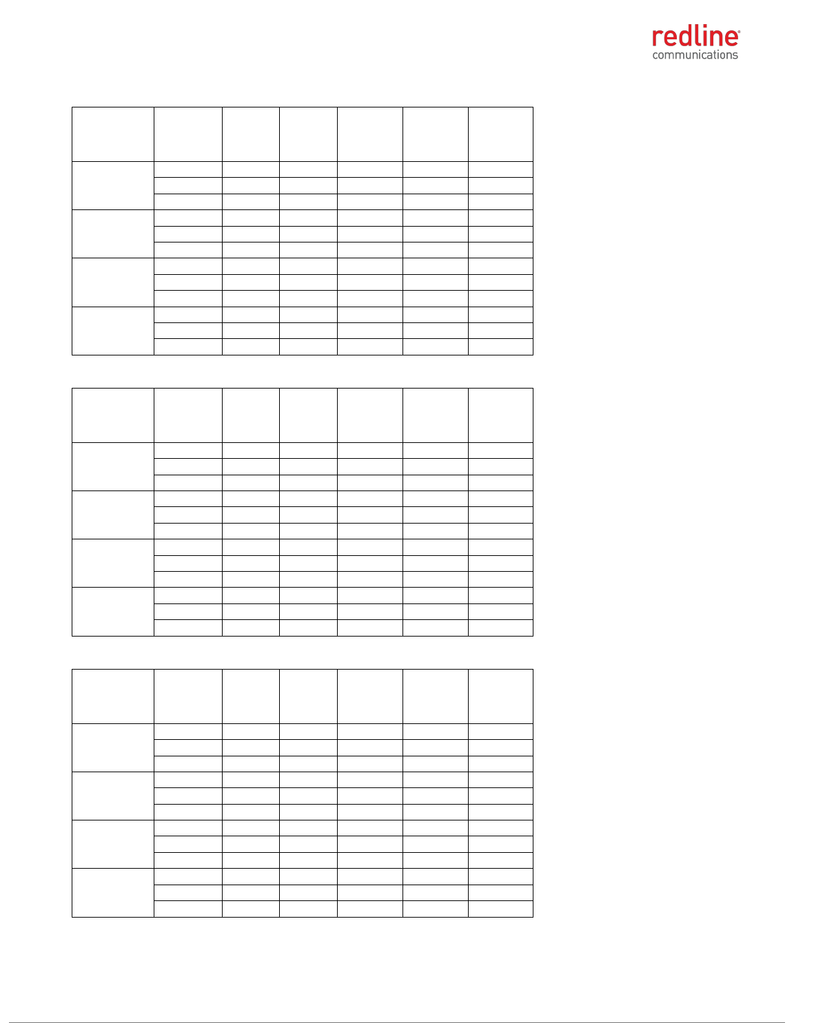
RDL-3000 RMC/E/F MODULE PRODUCT MANUAL
70-00184-03-02 Proprietary Redline Communications © 2013 Page 20 of 50 April 30, 2013
Table 32: 5.3 GHz: RF Power: 10 MHz channel & 10 dBi antenna for FCC
Modulation
Frequency
MHz
Power
at RF-1
(dBm)
Power
at RF-2
(dBm)
Combined
output
power
(dBm)
Output
power
limit
(dBm)
Output
power
margin
(dB)
BPSK
5255.0
10.54
10.49
13.53
16.68
3.16
5300.0
10.46
10.81
13.65
16.68
3.03
5342.5
10.69
11.54
14.15
16.68
2.54
QPSK
5255.0
10.50
10.51
13.52
16.68
3.17
5300.0
10.48
10.80
13.65
16.68
3.03
5342.5
10.63
11.55
14.12
16.68
2.56
16-QAM
5255.0
10.33
10.55
13.45
16.68
3.23
5300.0
10.49
10.81
13.66
16.68
3.02
5342.5
10.62
11.55
14.12
16.68
2.56
64-QAM
5255.0
10.37
10.67
13.53
16.68
3.15
5300.0
10.54
10.79
13.68
16.68
3.01
5342.5
10.63
11.55
14.12
16.68
2.56
Table 33: 5.3 GHz: RF Power: 10 MHz channel & 19 dBi antenna for FCC
Modulation
Frequency
MHz
Power
at RF-1
(dBm)
Power
at RF-2
(dBm)
Combined
output
power
(dBm)
Output
power
limit
(dBm)
Output
power
margin
(dB)
BPSK
5255.0
1.52
1.91
4.73
7.68
2.95
5300.0
1.58
1.83
4.72
7.68
2.97
5342.5
2.60
2.77
5.70
7.68
1.99
QPSK
5255.0
1.61
1.89
4.76
7.68
2.92
5300.0
1.60
1.84
4.73
7.68
2.95
5342.5
2.61
2.64
5.64
7.68
2.05
16-QAM
5255.0
1.60
1.87
4.75
7.68
2.94
5300.0
1.57
1.84
4.72
7.68
2.97
5342.5
2.58
2.53
5.57
7.68
2.12
64-QAM
5255.0
1.61
1.86
4.75
7.68
2.94
5300.0
1.64
1.85
4.76
7.68
2.93
5342.5
2.59
2.44
5.53
7.68
2.16
Table 34: 5.3 GHz: RF Power: 10 MHz channel & 32 dBi antenna for FCC
Modulation
Frequency
MHz
Power
at RF-1
(dBm)
Power
at RF-2
(dBm)
Combined
output
power
(dBm)
Output
power
limit
(dBm)
Output
power
margin
(dB)
BPSK
5255.0
-11.56
-11.33
-8.43
-5.32
3.12
5300.0
-11.57
-11.08
-8.31
-5.32
2.99
5342.5
-11.43
-11.50
-8.45
-5.32
3.14
QPSK
5255.0
-11.56
-11.31
-8.42
-5.32
3.11
5300.0
-11.59
-11.06
-8.31
-5.32
2.99
5342.5
-11.47
-11.49
-8.47
-5.32
3.15
16-QAM
5255.0
-11.59
-11.31
-8.44
-5.32
3.12
5300.0
-11.58
-11.07
-8.31
-5.32
2.99
5342.5
-11.33
-11.45
-8.38
-5.32
3.06
64-QAM
5255.0
-11.60
-11.30
-8.44
-5.32
3.12
5300.0
-11.51
-11.02
-8.25
-5.32
2.93
5342.5
-11.27
-11.47
-8.36
-5.32
3.04

RDL-3000 RMC/E/F MODULE PRODUCT MANUAL
70-00184-03-02 Proprietary Redline Communications © 2013 Page 21 of 50 April 30, 2013
Table 35: 5.3 GHz: RF Power: 20 MHz channel & 10 dBi antenna for FCC
Modulation
Frequency
MHz
Power
at RF-1
(dBm)
Power
at RF-2
(dBm)
Combined
output
power
(dBm)
Output
power
limit
(dBm)
Output
power
margin
(dB)
BPSK
5260.0
13.86
13.14
16.53
19.69
3.17
5300.0
13.97
13.15
16.59
19.69
3.10
5337.5
14.15
14.08
17.13
19.69
2.57
QPSK
5260.0
13.85
13.12
16.51
19.69
3.18
5300.0
13.95
13.17
16.59
19.69
3.10
5337.5
14.00
14.10
17.06
19.69
2.63
16-QAM
5260.0
13.84
13.12
16.51
19.69
3.19
5300.0
13.98
13.21
16.62
19.69
3.07
5337.5
13.99
14.11
17.06
19.69
2.63
64-QAM
5260.0
13.85
13.16
16.53
19.69
3.16
5300.0
13.96
13.24
16.63
19.69
3.07
5337.5
14.12
14.10
17.12
19.69
2.57
Table 36: 5.3 GHz: RF Power: 20 MHz channel & 19 dBi antenna for FCC
Modulation
Frequency
MHz
Power
at RF-1
(dBm)
Power
at RF-2
(dBm)
Combined
output
power
(dBm)
Output
power
limit
(dBm)
Output
power
margin
(dB)
BPSK
5260.0
4.88
4.09
7.51
10.69
3.18
5300.0
4.81
4.08
7.47
10.69
3.22
5337.5
5.02
4.98
8.01
10.69
2.68
QPSK
5260.0
4.85
4.10
7.50
10.69
3.19
5300.0
4.82
4.27
7.56
10.69
3.13
5337.5
4.94
4.97
7.97
10.69
2.73
16-QAM
5260.0
4.86
4.08
7.50
10.69
3.19
5300.0
4.88
4.33
7.62
10.69
3.07
5337.5
4.97
4.98
7.99
10.69
2.71
64-QAM
5260.0
4.88
4.10
7.52
10.69
3.17
5300.0
4.87
4.47
7.68
10.69
3.01
5337.5
4.87
4.98
7.94
10.69
2.76
Table 37: 5.3 GHz: RF Power: 20 MHz channel & 32 dBi antenna for FCC
Modulation
Frequency
MHz
Power
at RF-1
(dBm)
Power
at RF-2
(dBm)
Combined
output
power
(dBm)
Output
power
limit
(dBm)
Output
power
margin
(dB)
BPSK
5260.0
-8.30
-8.11
-5.19
-2.31
2.89
5300.0
-8.56
-8.21
-5.37
-2.31
3.06
5337.5
-8.01
-8.10
-5.04
-2.31
2.74
QPSK
5260.0
-8.25
-8.15
-5.19
-2.31
2.88
5300.0
-8.55
-8.21
-5.37
-2.31
3.06
5337.5
-8.03
-8.09
-5.05
-2.31
2.74
16-QAM
5260.0
-8.29
-8.19
-5.23
-2.31
2.92
5300.0
-8.59
-8.20
-5.38
-2.31
3.07
5337.5
-8.02
-8.08
-5.04
-2.31
2.73
64-QAM
5260.0
-8.31
-8.20
-5.24
-2.31
2.94
5300.0
-8.67
-8.00
-5.31
-2.31
3.00
5337.5
-8.02
-8.08
-5.04
-2.31
2.73

RDL-3000 RMC/E/F MODULE PRODUCT MANUAL
70-00184-03-02 Proprietary Redline Communications © 2013 Page 22 of 50 April 30, 2013
5.3 GHz: IC RSS-210, Issue 8 Annex 9
Table 38: 5.3 GHz: RF Power & EIRP: 5 MHz channel & 10 dBi antenna for IC
Modulation
Frequency
MHz
Power
at RF-1
(dBm)
Power
at RF-2
(dBm)
Combined
output
power
(dBm)
Output
power
limit
(dBm)
Output
power
margin
(dB)
Antenna
gain (dBi)
EIRP
(dBm)
EIRP limit
(dBm)
EIRP
margin
(dB)
BPSK
5252.5
10.40
9.47
12.97
17.17
4.20
10.00
22.97
23.17
0.20
5300.0
10.33
9.45
12.92
17.17
4.25
10.00
22.92
23.17
0.25
5345.0
10.48
9.27
12.93
17.17
4.24
10.00
22.93
23.17
0.24
QPSK
5252.5
10.42
9.38
12.94
17.17
4.23
10.00
22.94
23.17
0.23
5300.0
10.41
9.46
12.97
17.17
4.20
10.00
22.97
23.17
0.20
5345.0
10.48
9.22
12.91
17.17
4.26
10.00
22.91
23.17
0.26
16-QAM
5252.5
10.41
9.41
12.95
17.17
4.22
10.00
22.95
23.17
0.22
5300.0
10.30
9.48
12.92
17.17
4.25
10.00
22.92
23.17
0.25
5345.0
10.47
9.26
12.92
17.17
4.25
10.00
22.92
23.17
0.25
64-QAM
5252.5
10.41
9.37
12.93
17.17
4.24
10.00
22.93
23.17
0.24
5300.0
10.28
9.48
12.91
17.17
4.26
10.00
22.91
23.17
0.26
5345.0
10.30
9.28
12.83
17.17
4.34
10.00
22.83
23.17
0.34
Table 39: 5.3 GHz: RF Power & EIRP: 5 MHz channel & 19 dBi antenna for IC
Modulation
Frequency
MHz
Power
at RF-1
(dBm)
Power
at RF-2
(dBm)
Combined
output
power
(dBm)
Output
power
limit
(dBm)
Output
power
margin
(dB)
Antenna
gain (dBi)
EIRP
(dBm)
EIRP limit
(dBm)
EIRP
margin
(dB)
BPSK
5252.5
1.28
0.56
3.95
17.17
13.22
19.00
22.95
23.17
0.22
5300.0
1.34
0.56
3.98
17.17
13.19
19.00
22.98
23.17
0.19
5345.0
1.36
0.52
3.97
17.17
13.20
19.00
22.97
23.17
0.20
QPSK
5252.5
1.28
0.55
3.94
17.17
13.23
19.00
22.94
23.17
0.23
5300.0
1.40
0.52
3.99
17.17
13.18
19.00
22.99
23.17
0.18
5345.0
1.38
0.51
3.98
17.17
13.19
19.00
22.98
23.17
0.19
16-QAM
5252.5
1.29
0.55
3.95
17.17
13.22
19.00
22.95
23.17
0.22
5300.0
1.42
0.49
3.99
17.17
13.18
19.00
22.99
23.17
0.18
5345.0
1.38
0.53
3.99
17.17
13.18
19.00
22.99
23.17
0.18
64-QAM
5252.5
1.25
0.48
3.89
17.17
13.28
19.00
22.89
23.17
0.28
5300.0
1.41
0.51
3.99
17.17
13.18
19.00
22.99
23.17
0.18
5345.0
1.37
0.51
3.97
17.17
13.20
19.00
22.97
23.17
0.20
Table 40: 5.3 GHz: RF Power & EIRP: 5 MHz channel & 32 dBi antenna for IC
Modulation
Frequency
MHz
Power
at RF-1
(dBm)
Power
at RF-2
(dBm)
Combined
output
power
(dBm)
Output
power
limit
(dBm)
Output
power
margin
(dB)
Antenna
gain (dBi)
EIRP
(dBm)
EIRP limit
(dBm)
EIRP
margin
(dB)
BPSK
5252.5
-11.54
-12.56
-9.01
17.17
26.18
32.00
22.99
23.17
0.18
5300.0
-11.56
-12.63
-9.05
17.17
26.22
32.00
22.95
23.17
0.22
5345.0
-11.55
-12.69
-9.07
17.17
26.24
32.00
22.93
23.17
0.24
QPSK
5252.5
-11.55
-12.55
-9.01
17.17
26.18
32.00
22.99
23.17
0.18
5300.0
-11.52
-12.59
-9.01
17.17
26.18
32.00
22.99
23.17
0.18
5345.0
-11.55
-12.66
-9.06
17.17
26.23
32.00
22.94
23.17
0.23
16-QAM
5252.5
-11.58
-12.54
-9.02
17.17
26.19
32.00
22.98
23.17
0.19
5300.0
-11.59
-12.68
-9.09
17.17
26.26
32.00
22.91
23.17
0.26
5345.0
-11.54
-12.65
-9.05
17.17
26.22
32.00
22.95
23.17
0.22
64-QAM
5252.5
-11.57
-12.52
-9.01
17.17
26.18
32.00
22.99
23.17
0.18
5300.0
-11.57
-12.66
-9.07
17.17
26.24
32.00
22.93
23.17
0.24
5345.0
-11.51
-12.65
-9.03
17.17
26.20
32.00
22.97
23.17
0.20
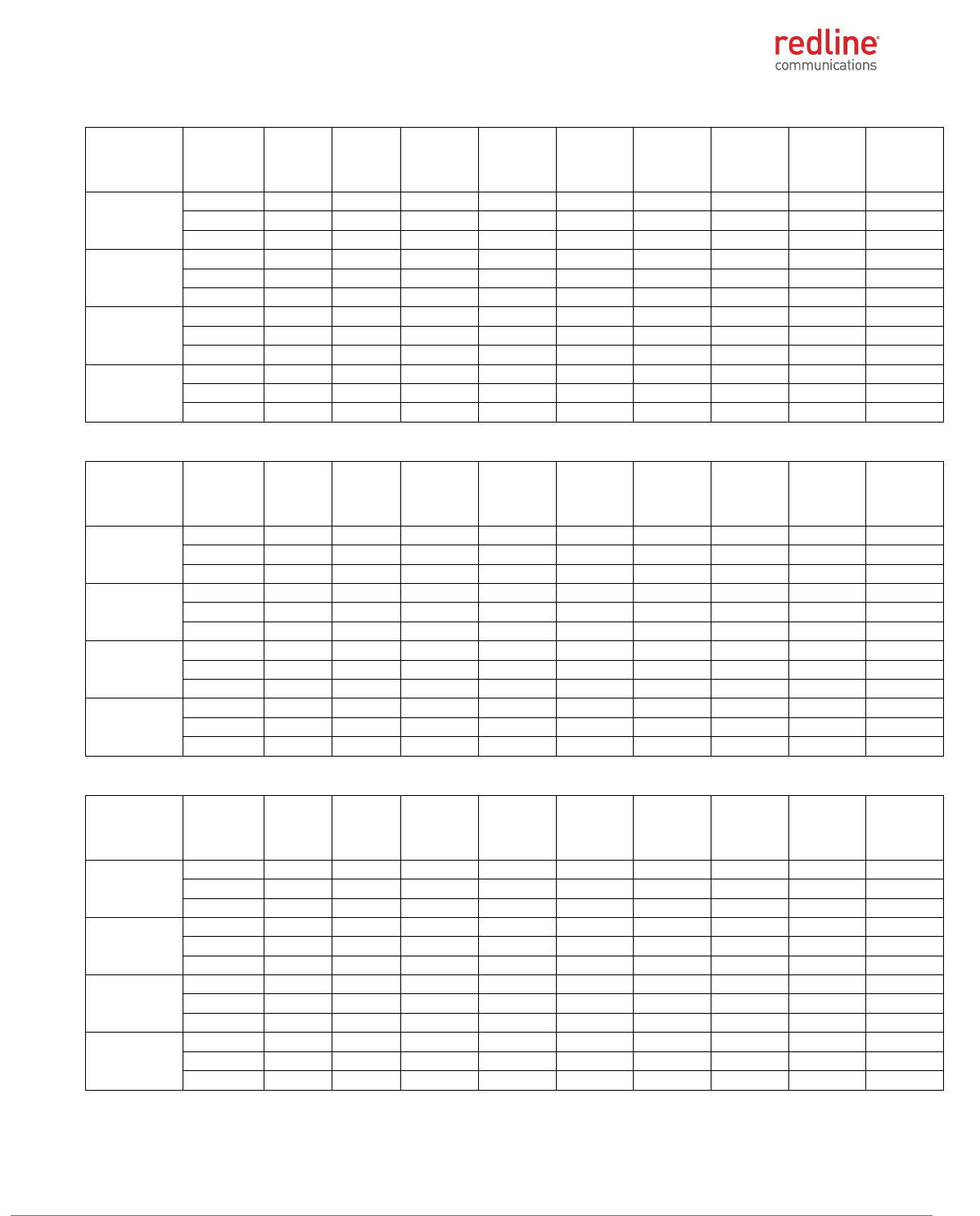
RDL-3000 RMC/E/F MODULE PRODUCT MANUAL
70-00184-03-02 Proprietary Redline Communications © 2013 Page 23 of 50 April 30, 2013
Table 41: 5.3 GHz: RF Power & EIRP: 10 MHz channel & 10 dBi antenna for IC
Modulation
Frequency
MHz
Power
at RF-1
(dBm)
Power
at RF-2
(dBm)
Combined
output
power
(dBm)
Output
power
limit
(dBm)
Output
power
margin
(dB)
Antenna
gain (dBi)
EIRP
(dBm)
EIRP limit
(dBm)
EIRP
margin
(dB)
BPSK
5255.0
10.37
9.38
12.91
20.18
7.26
10.00
22.91
26.18
3.26
5300.0
10.36
8.68
12.61
20.18
7.56
10.00
22.61
26.18
3.56
5342.5
10.48
9.32
12.95
20.18
7.23
10.00
22.95
26.18
3.23
QPSK
5255.0
10.35
9.35
12.89
20.18
7.29
10.00
22.89
26.18
3.29
5300.0
10.37
8.72
12.63
20.18
7.54
10.00
22.63
26.18
3.54
5342.5
10.47
9.33
12.95
20.18
7.23
10.00
22.95
26.18
3.23
16-QAM
5255.0
10.36
9.34
12.89
20.18
7.28
10.00
22.89
26.18
3.28
5300.0
10.44
8.69
12.66
20.18
7.51
10.00
22.66
26.18
3.51
5342.5
10.50
9.35
12.97
20.18
7.20
10.00
22.97
26.18
3.20
64-QAM
5255.0
10.36
9.36
12.90
20.18
7.28
10.00
22.90
26.18
3.28
5300.0
10.43
8.79
12.70
20.18
7.48
10.00
22.70
26.18
3.48
5342.5
10.54
9.32
12.98
20.18
7.19
10.00
22.98
26.18
3.19
Table 42: 5.3 GHz: RF Power & EIRP: 10 MHz channel & 19 dBi antenna for IC
Modulation
Frequency
MHz
Power
at RF-1
(dBm)
Power
at RF-2
(dBm)
Combined
output
power
(dBm)
Output
power
limit
(dBm)
Output
power
margin
(dB)
Antenna
gain (dBi)
EIRP
(dBm)
EIRP limit
(dBm)
EIRP
margin
(dB)
BPSK
5255.0
0.31
0.64
3.49
20.18
16.69
19.00
22.49
26.18
3.69
5300.0
0.43
0.81
3.63
20.18
16.54
19.00
22.63
26.18
3.54
5342.5
1.48
0.33
3.95
20.18
16.22
19.00
22.95
26.18
3.22
QPSK
5255.0
0.33
0.61
3.48
20.18
16.69
19.00
22.48
26.18
3.69
5300.0
0.41
0.83
3.64
20.18
16.54
19.00
22.64
26.18
3.54
5342.5
1.44
0.34
3.94
20.18
16.24
19.00
22.94
26.18
3.24
16-QAM
5255.0
0.36
0.63
3.51
20.18
16.67
19.00
22.51
26.18
3.67
5300.0
0.41
0.83
3.64
20.18
16.54
19.00
22.64
26.18
3.54
5342.5
1.46
0.34
3.95
20.18
16.23
19.00
22.95
26.18
3.23
64-QAM
5255.0
0.35
0.60
3.49
20.18
16.69
19.00
22.49
26.18
3.69
5300.0
0.35
0.87
3.63
20.18
16.55
19.00
22.63
26.18
3.55
5342.5
1.53
0.33
3.98
20.18
16.19
19.00
22.98
26.18
3.19
Table 43: 5.3 GHz: RF Power & EIRP: 10 MHz channel & 32 dBi antenna for IC
Modulation
Frequency
MHz
Power
at RF-1
(dBm)
Power
at RF-2
(dBm)
Combined
output
power
(dBm)
Output
power
limit
(dBm)
Output
power
margin
(dB)
Antenna
gain (dBi)
EIRP
(dBm)
EIRP limit
(dBm)
EIRP
margin
(dB)
BPSK
5255.0
-11.65
-12.65
-9.11
20.18
29.29
32.00
22.89
26.18
3.29
5300.0
-11.64
-12.44
-9.01
20.18
29.19
32.00
22.99
26.18
3.19
5342.5
-12.56
-12.59
-9.56
20.18
29.74
32.00
22.44
26.18
3.74
QPSK
5255.0
-11.60
-12.64
-9.08
20.18
29.25
32.00
22.92
26.18
3.25
5300.0
-11.65
-12.45
-9.02
20.18
29.20
32.00
22.98
26.18
3.20
5342.5
-12.51
-12.57
-9.53
20.18
29.70
32.00
22.47
26.18
3.70
16-QAM
5255.0
-11.61
-12.66
-9.09
20.18
29.27
32.00
22.91
26.18
3.27
5300.0
-11.66
-12.44
-9.02
20.18
29.20
32.00
22.98
26.18
3.20
5342.5
-12.49
-12.60
-9.53
20.18
29.71
32.00
22.47
26.18
3.71
64-QAM
5255.0
-11.59
-12.62
-9.06
20.18
29.24
32.00
22.94
26.18
3.24
5300.0
-11.66
-12.43
-9.02
20.18
29.19
32.00
22.98
26.18
3.19
5342.5
-12.49
-12.62
-9.54
20.18
29.72
32.00
22.46
26.18
3.72
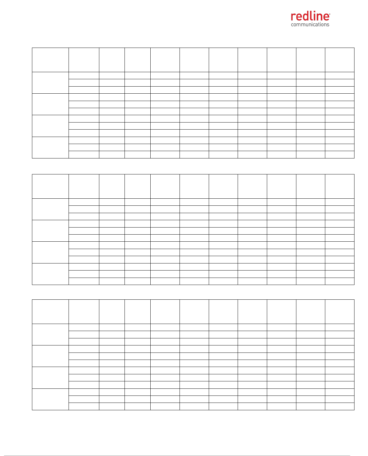
RDL-3000 RMC/E/F MODULE PRODUCT MANUAL
70-00184-03-02 Proprietary Redline Communications © 2013 Page 24 of 50 April 30, 2013
Table 44: 5.3 GHz: RF Power & EIRP: 20 MHz channel & 10 dBi antenna for IC
Modulation
Frequency
MHz
Power
at RF-1
(dBm)
Power
at RF-2
(dBm)
Combined
output
power
(dBm)
Output
power
limit
(dBm)
Output
power
margin
(dB)
Antenna
gain (dBi)
EIRP
(dBm)
EIRP limit
(dBm)
EIRP
margin
(dB)
BPSK
5260.0
9.81
9.97
12.90
23.16
10.26
10.00
22.90
29.16
6.26
5300.0
9.70
10.20
12.97
23.16
10.19
10.00
22.97
29.16
6.19
5337.5
9.97
9.92
12.96
23.16
10.20
10.00
22.96
29.16
6.20
QPSK
5260.0
9.77
10.00
12.90
23.16
10.26
10.00
22.90
29.16
6.26
5300.0
9.65
10.16
12.92
23.16
10.24
10.00
22.92
29.16
6.24
5337.5
9.94
9.92
12.94
23.16
10.22
10.00
22.94
29.16
6.22
16-QAM
5260.0
9.75
9.99
12.88
23.16
10.28
10.00
22.88
29.16
6.28
5300.0
9.69
10.18
12.95
23.16
10.21
10.00
22.95
29.16
6.21
5337.5
9.92
9.95
12.95
23.16
10.21
10.00
22.95
29.16
6.21
64-QAM
5260.0
9.73
10.00
12.88
23.16
10.28
10.00
22.88
29.16
6.28
5300.0
9.76
10.17
12.98
23.16
10.18
10.00
22.98
29.16
6.18
5337.5
9.92
9.94
12.94
23.16
10.22
10.00
22.94
29.16
6.22
Table 45: 5.3 GHz: RF Power & EIRP: 20 MHz channel & 19 dBi antenna for IC
Modulation
Frequency
MHz
Power
at RF-1
(dBm)
Power
at RF-2
(dBm)
Combined
output
power
(dBm)
Output
power
limit
(dBm)
Output
power
margin
(dB)
Antenna
gain (dBi)
EIRP
(dBm)
EIRP limit
(dBm)
EIRP
margin
(dB)
BPSK
5260.0
0.62
1.19
3.92
23.16
19.23
19.00
22.92
29.16
6.23
5300.0
0.70
0.92
3.82
23.16
19.34
19.00
22.82
29.16
6.34
5337.5
0.93
-0.06
3.47
23.16
19.69
19.00
22.47
29.16
6.69
QPSK
5260.0
0.61
1.18
3.91
23.16
19.24
19.00
22.91
29.16
6.24
5300.0
0.78
0.93
3.87
23.16
19.29
19.00
22.87
29.16
6.29
5337.5
0.94
-0.09
3.47
23.16
19.69
19.00
22.47
29.16
6.69
16-QAM
5260.0
0.62
1.10
3.88
23.16
19.28
19.00
22.88
29.16
6.28
5300.0
0.80
0.94
3.88
23.16
19.28
19.00
22.88
29.16
6.28
5337.5
1.00
-0.10
3.50
23.16
19.66
19.00
22.50
29.16
6.66
64-QAM
5260.0
0.62
1.02
3.83
23.16
19.32
19.00
22.83
29.16
6.32
5300.0
0.82
0.93
3.89
23.16
19.27
19.00
22.89
29.16
6.27
5337.5
0.97
-0.09
3.48
23.16
19.68
19.00
22.48
29.16
6.68
Table 46: 5.3 GHz: RF Power & EIRP: 20 MHz channel & 32 dBi antenna for IC
Modulation
Frequency
MHz
Power
at RF-1
(dBm)
Power
at RF-2
(dBm)
Combined
output
power
(dBm)
Output
power
limit
(dBm)
Output
power
margin
(dB)
Antenna
gain (dBi)
EIRP
(dBm)
EIRP limit
(dBm)
EIRP
margin
(dB)
BPSK
5260.0
-12.14
-12.02
-9.07
23.16
32.23
32.00
22.93
29.16
6.23
5300.0
-12.15
-11.91
-9.02
23.16
32.18
32.00
22.98
29.16
6.18
5337.5
-12.20
-11.91
-9.04
23.16
32.20
32.00
22.96
29.16
6.20
QPSK
5260.0
-12.14
-12.01
-9.06
23.16
32.22
32.00
22.94
29.16
6.22
5300.0
-12.19
-11.88
-9.02
23.16
32.18
32.00
22.98
29.16
6.18
5337.5
-12.18
-11.93
-9.04
23.16
32.20
32.00
22.96
29.16
6.20
16-QAM
5260.0
-12.19
-12.00
-9.08
23.16
32.24
32.00
22.92
29.16
6.24
5300.0
-12.18
-11.96
-9.06
23.16
32.22
32.00
22.94
29.16
6.22
5337.5
-12.22
-11.96
-9.08
23.16
32.24
32.00
22.92
29.16
6.24
64-QAM
5260.0
-12.22
-12.00
-9.10
23.16
32.26
32.00
22.90
29.16
6.26
5300.0
-12.21
-11.84
-9.01
23.16
32.17
32.00
22.99
29.16
6.17
5337.5
-12.19
-11.96
-9.06
23.16
32.22
32.00
22.94
29.16
6.22
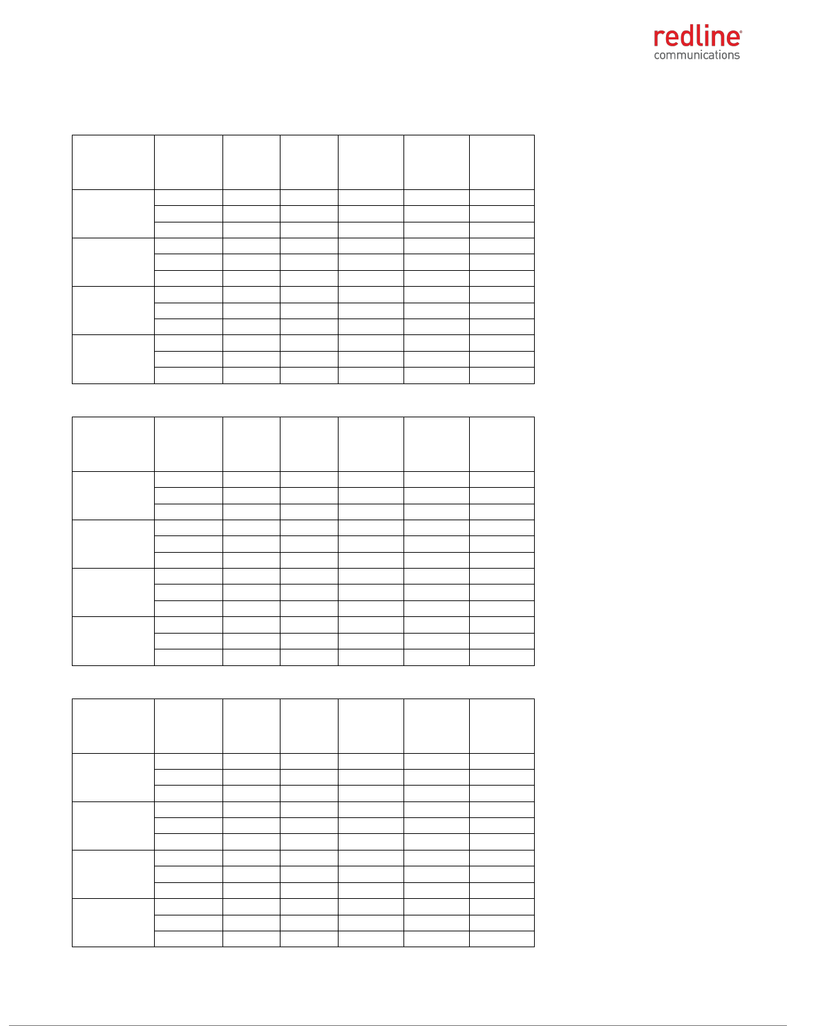
RDL-3000 RMC/E/F MODULE PRODUCT MANUAL
70-00184-03-02 Proprietary Redline Communications © 2013 Page 25 of 50 April 30, 2013
5.4 GHz: FCC 47 CFR Part 15 Subpart E, §15.407
Table 47: 5.4 GHz: RF Power: 5 MHz channel & 10 dBi antenna for FCC
Modulation
Frequency
MHz
Power
at RF-1
(dBm)
Power
at RF-2
(dBm)
Combined
output
power
(dBm)
Output
power
limit
(dBm)
Output
power
margin
(dB)
BPSK
5472.5
7.93
7.91
10.93
13.65
2.72
5570.0
8.31
7.58
10.97
13.65
2.68
5722.5
8.60
8.10
11.37
13.65
2.28
QPSK
5472.5
7.95
7.82
10.90
13.65
2.75
5570.0
8.20
7.55
10.90
13.65
2.75
5722.5
8.61
7.97
11.31
13.65
2.33
16-QAM
5472.5
7.99
7.77
10.89
13.65
2.75
5570.0
8.17
7.66
10.93
13.65
2.71
5722.5
8.57
7.99
11.30
13.65
2.35
64-QAM
5472.5
7.99
7.68
10.85
13.65
2.80
5570.0
8.15
7.56
10.88
13.65
2.77
5722.5
8.55
7.91
11.25
13.65
2.39
Table 48: 5.4 GHz: RF Power: 5 MHz channel & 19 dBi antenna for FCC
Modulation
Frequency
MHz
Power
at RF-1
(dBm)
Power
at RF-2
(dBm)
Combined
output
power
(dBm)
Output
power
limit
(dBm)
Output
power
margin
(dB)
BPSK
5472.5
-1.00
-1.48
1.78
4.65
2.87
5570.0
-0.73
-1.46
1.93
4.65
2.72
5722.5
0.40
-0.41
3.02
4.65
1.62
QPSK
5472.5
-1.01
-1.50
1.76
4.65
2.88
5570.0
-0.77
-1.48
1.90
4.65
2.75
5722.5
0.44
-0.41
3.05
4.65
1.60
16-QAM
5472.5
-1.02
-1.51
1.75
4.65
2.89
5570.0
-0.75
-1.52
1.89
4.65
2.75
5722.5
0.53
-0.43
3.09
4.65
1.56
64-QAM
5472.5
-1.02
-1.55
1.73
4.65
2.91
5570.0
-0.71
-1.55
1.90
4.65
2.75
5722.5
0.59
-0.42
3.12
4.65
1.52
Table 49: 5.4 GHz: RF Power: 5 MHz channel & 32 dBi antenna for FCC
Modulation
Frequency
MHz
Power
at RF-1
(dBm)
Power
at RF-2
(dBm)
Combined
output
power
(dBm)
Output
power
limit
(dBm)
Output
power
margin
(dB)
BPSK
5472.5
-14.23
-14.92
-11.55
-8.35
3.20
5570.0
-13.65
-14.25
-10.93
-8.35
2.58
5722.5
-12.96
-13.55
-10.23
-8.35
1.88
QPSK
5472.5
-14.37
-15.05
-11.69
-8.35
3.33
5570.0
-13.66
-14.30
-10.96
-8.35
2.60
5722.5
-12.99
-13.44
-10.20
-8.35
1.85
16-QAM
5472.5
-14.44
-14.99
-11.70
-8.35
3.34
5570.0
-13.71
-14.33
-11.00
-8.35
2.65
5722.5
-13.01
-13.49
-10.23
-8.35
1.88
64-QAM
5472.5
-14.58
-14.80
-11.68
-8.35
3.32
5570.0
-13.68
-14.29
-10.96
-8.35
2.61
5722.5
-13.00
-13.46
-10.21
-8.35
1.86

RDL-3000 RMC/E/F MODULE PRODUCT MANUAL
70-00184-03-02 Proprietary Redline Communications © 2013 Page 26 of 50 April 30, 2013
Table 50: 5.4 GHz: RF Power: 10 MHz channel & 10 dBi antenna for FCC
Modulation
Frequency
MHz
Power
at RF-1
(dBm)
Power
at RF-2
(dBm)
Combined
output
power
(dBm)
Output
power
limit
(dBm)
Output
power
margin
(dB)
BPSK
5475.0
10.33
11.13
13.76
16.63
2.87
5570.0
10.69
10.29
13.50
16.63
3.12
5720.0
11.07
10.79
13.94
16.63
2.69
QPSK
5475.0
10.25
11.13
13.72
16.63
2.91
5570.0
10.72
10.30
13.53
16.63
3.10
5720.0
11.09
10.80
13.96
16.63
2.67
16-QAM
5475.0
10.26
11.14
13.73
16.63
2.90
5570.0
10.73
10.33
13.54
16.63
3.08
5720.0
11.10
10.82
13.97
16.63
2.66
64-QAM
5475.0
10.27
11.11
13.72
16.63
2.91
5570.0
10.74
10.43
13.60
16.63
3.03
5720.0
11.09
10.84
13.98
16.63
2.65
Table 51: 5.4 GHz: RF Power: 10 MHz channel & 19 dBi antenna for FCC
Modulation
Frequency
MHz
Power
at RF-1
(dBm)
Power
at RF-2
(dBm)
Combined
output
power
(dBm)
Output
power
limit
(dBm)
Output
power
margin
(dB)
BPSK
5475.0
1.98
0.79
4.44
7.63
3.19
5570.0
1.34
0.61
4.00
7.63
3.63
5720.0
2.00
1.45
4.74
7.63
2.88
QPSK
5475.0
1.99
0.77
4.43
7.63
3.20
5570.0
1.30
0.61
3.98
7.63
3.65
5720.0
2.01
1.44
4.74
7.63
2.88
16-QAM
5475.0
2.00
0.75
4.43
7.63
3.20
5570.0
1.31
0.61
3.98
7.63
3.64
5720.0
2.01
1.44
4.74
7.63
2.88
64-QAM
5475.0
2.02
0.79
4.46
7.63
3.17
5570.0
1.31
0.61
3.98
7.63
3.64
5720.0
2.01
1.50
4.77
7.63
2.86
Table 52: 5.4 GHz: RF Power: 10 MHz channel & 32 dBi antenna for FCC
Modulation
Frequency
MHz
Power
at RF-1
(dBm)
Power
at RF-2
(dBm)
Combined
output
power
(dBm)
Output
power
limit
(dBm)
Output
power
margin
(dB)
BPSK
5475.0
-11.03
-11.85
-8.41
-5.37
3.04
5570.0
-11.61
-11.97
-8.78
-5.37
3.40
5720.0
-11.10
-12.05
-8.54
-5.37
3.17
QPSK
5475.0
-11.00
-11.83
-8.38
-5.37
3.01
5570.0
-11.62
-11.95
-8.77
-5.37
3.40
5720.0
-11.10
-12.00
-8.52
-5.37
3.14
16-QAM
5475.0
-10.99
-11.81
-8.37
-5.37
3.00
5570.0
-11.61
-11.93
-8.76
-5.37
3.39
5720.0
-11.10
-11.92
-8.48
-5.37
3.11
64-QAM
5475.0
-10.99
-11.81
-8.37
-5.37
3.00
5570.0
-11.60
-11.93
-8.75
-5.37
3.38
5720.0
-11.11
-11.74
-8.40
-5.37
3.03
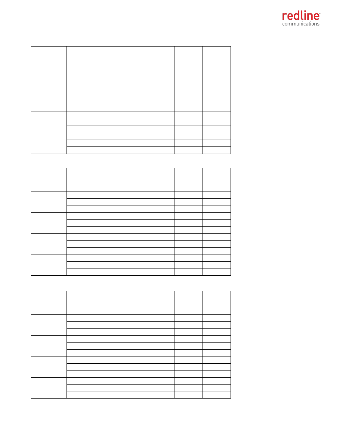
RDL-3000 RMC/E/F MODULE PRODUCT MANUAL
70-00184-03-02 Proprietary Redline Communications © 2013 Page 27 of 50 April 30, 2013
Table 53: 5.4 GHz: RF Power: 20 MHz channel & 10 dBi antenna for FCC
Modulation
Frequency
MHz
Power
at RF-1
(dBm)
Power
at RF-2
(dBm)
Combined
output
power
(dBm)
Output
power
limit
(dBm)
Output
power
margin
(dB)
BPSK
5480.0
14.05
13.49
16.79
19.66
2.87
5570.0
13.32
13.65
16.50
19.66
3.16
5715.0
13.78
13.09
16.46
19.66
3.20
QPSK
5480.0
14.07
13.51
16.81
19.66
2.85
5570.0
13.33
13.68
16.52
19.66
3.14
5715.0
13.48
13.10
16.30
19.66
3.35
16-QAM
5480.0
14.08
13.53
16.82
19.66
2.83
5570.0
13.34
13.72
16.54
19.66
3.11
5715.0
13.76
13.11
16.46
19.66
3.20
64-QAM
5480.0
14.08
13.56
16.84
19.66
2.82
5570.0
13.35
13.86
16.62
19.66
3.03
5715.0
13.77
13.12
16.47
19.66
3.19
Table 54: 5.4 GHz: RF Power: 20 MHz channel & 19 dBi antenna for FCC
Modulation
Frequency
MHz
Power
at RF-1
(dBm)
Power
at RF-2
(dBm)
Combined
output
power
(dBm)
Output
power
limit
(dBm)
Output
power
margin
(dB)
BPSK
5480.0
4.42
5.11
7.79
10.66
2.87
5570.0
4.74
5.03
7.90
10.66
2.76
5715.0
4.74
4.37
7.57
10.66
3.09
QPSK
5480.0
4.41
5.11
7.78
10.66
2.87
5570.0
4.75
5.03
7.90
10.66
2.76
5715.0
4.78
4.40
7.60
10.66
3.05
16-QAM
5480.0
4.41
5.11
7.78
10.66
2.87
5570.0
4.75
5.03
7.90
10.66
2.76
5715.0
4.79
4.41
7.61
10.66
3.04
64-QAM
5480.0
4.41
5.12
7.79
10.66
2.87
5570.0
4.75
5.02
7.90
10.66
2.76
5715.0
4.71
4.45
7.59
10.66
3.07
Table 55: 5.4 GHz: RF Power: 20 MHz channel & 32 dBi antenna for FCC
Modulation
Frequency
MHz
Power
at RF-1
(dBm)
Power
at RF-2
(dBm)
Combined
output
power
(dBm)
Output
power
limit
(dBm)
Output
power
margin
(dB)
BPSK
5480.0
-8.56
-8.28
-5.41
-2.34
3.07
5570.0
-8.45
-8.88
-5.65
-2.34
3.31
5715.0
-8.12
-8.61
-5.35
-2.34
3.01
QPSK
5480.0
-8.55
-8.25
-5.39
-2.34
3.04
5570.0
-8.45
-8.91
-5.66
-2.34
3.32
5715.0
-8.13
-8.66
-5.38
-2.34
3.03
16-QAM
5480.0
-8.53
-8.26
-5.38
-2.34
3.04
5570.0
-8.44
-8.92
-5.66
-2.34
3.32
5715.0
-8.14
-8.64
-5.37
-2.34
3.03
64-QAM
5480.0
-8.52
-8.25
-5.37
-2.34
3.03
5570.0
-8.43
-8.93
-5.66
-2.34
3.32
5715.0
-8.16
-8.58
-5.35
-2.34
3.01
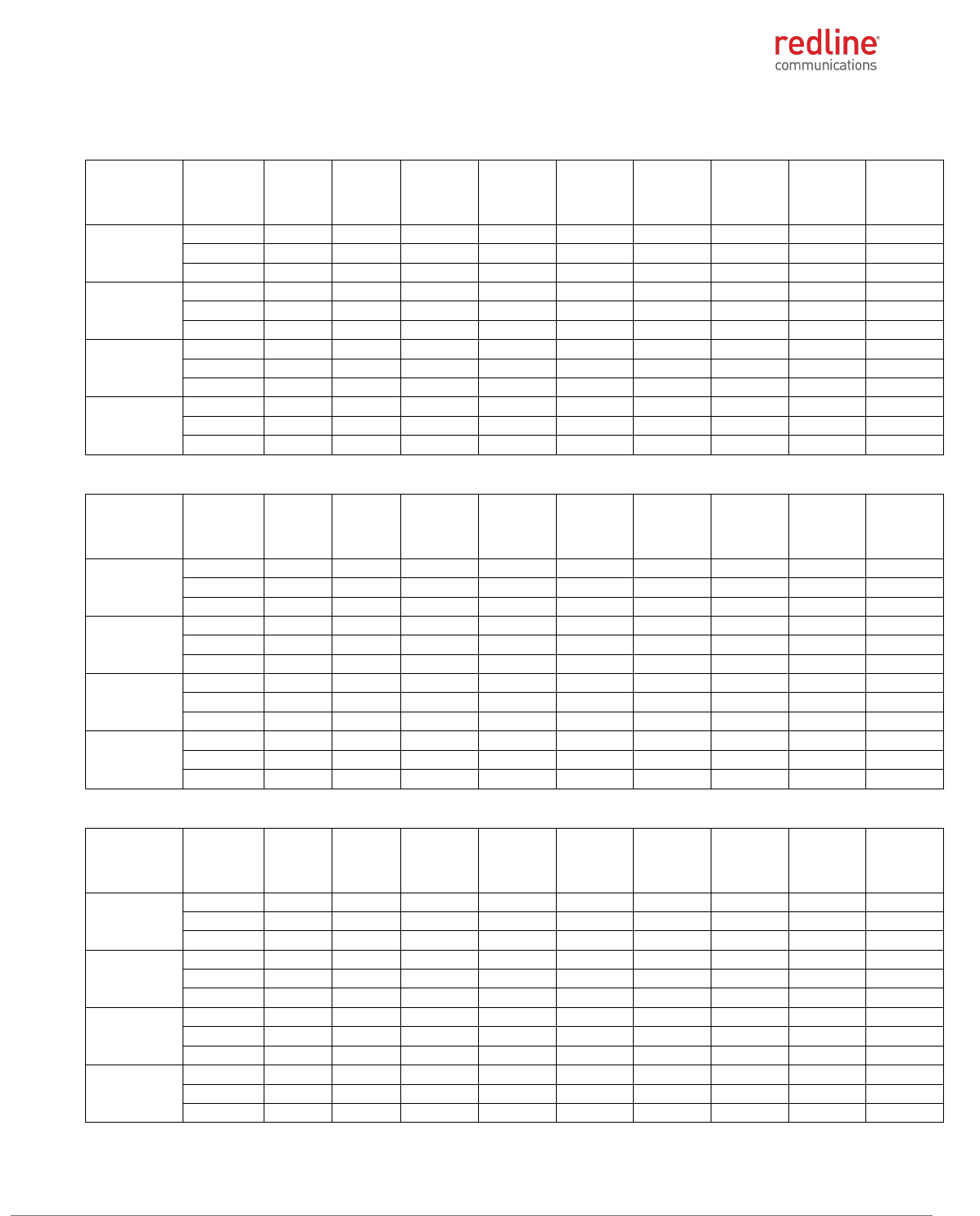
RDL-3000 RMC/E/F MODULE PRODUCT MANUAL
70-00184-03-02 Proprietary Redline Communications © 2013 Page 28 of 50 April 30, 2013
5.4 GHz: FCC 47 CFR Part 15 Subpart E, §15.407 / IC RSS-210, Issue 8 Annex 9
Table 56: 5.4 GHz: RF Power & EIRP: 5 MHz channel & 10 dBi antenna for IC
Modulation
Frequency
MHz
Power
at RF-1
(dBm)
Power
at RF-2
(dBm)
Combined
output
power
(dBm)
Output
power
limit
(dBm)
Output
power
margin
(dB)
Antenna
gain (dBi)
EIRP
(dBm)
EIRP limit
(dBm)
EIRP
margin
(dB)
BPSK
5472.5
10.22
9.80
13.03
17.15
4.12
10.00
23.03
23.15
0.12
5570.0
10.33
9.71
13.04
17.15
4.11
10.00
23.04
23.15
0.11
5722.5
10.75
9.26
13.08
17.15
4.07
10.00
23.08
23.15
0.07
QPSK
5472.5
10.19
9.72
12.97
17.15
4.18
10.00
22.97
23.15
0.18
5570.0
10.40
9.73
13.09
17.15
4.06
10.00
23.09
23.15
0.06
5722.5
10.71
9.26
13.06
17.15
4.09
10.00
23.06
23.15
0.09
16-QAM
5472.5
10.21
9.91
13.07
17.15
4.08
10.00
23.07
23.15
0.08
5570.0
10.41
9.69
13.08
17.15
4.07
10.00
23.08
23.15
0.07
5722.5
10.74
9.26
13.07
17.15
4.08
10.00
23.07
23.15
0.08
64-QAM
5472.5
10.22
9.98
13.11
17.15
4.04
10.00
23.11
23.15
0.04
5570.0
10.43
9.65
13.07
17.15
4.08
10.00
23.07
23.15
0.08
5722.5
10.79
9.28
13.11
17.15
4.04
10.00
23.11
23.15
0.04
Table 57: 5.4 GHz: RF Power & EIRP: 5 MHz channel & 19 dBi antenna for IC
Modulation
Frequency
MHz
Power
at RF-1
(dBm)
Power
at RF-2
(dBm)
Combined
output
power
(dBm)
Output
power
limit
(dBm)
Output
power
margin
(dB)
Antenna
gain (dBi)
EIRP
(dBm)
EIRP limit
(dBm)
EIRP
margin
(dB)
BPSK
5472.5
0.99
0.39
3.71
17.15
13.44
19.00
22.71
23.15
0.44
5570.0
1.20
0.84
4.03
17.15
13.11
19.00
23.03
23.15
0.11
5722.5
0.77
0.81
3.80
17.15
13.35
19.00
22.80
23.15
0.35
QPSK
5472.5
1.00
0.40
3.72
17.15
13.43
19.00
22.72
23.15
0.43
5570.0
1.21
0.83
4.03
17.15
13.11
19.00
23.03
23.15
0.11
5722.5
0.77
0.80
3.80
17.15
13.35
19.00
22.80
23.15
0.35
16-QAM
5472.5
1.01
0.40
3.73
17.15
13.42
19.00
22.73
23.15
0.42
5570.0
1.22
0.83
4.04
17.15
13.11
19.00
23.04
23.15
0.11
5722.5
0.79
0.81
3.81
17.15
13.34
19.00
22.81
23.15
0.34
64-QAM
5472.5
1.07
0.41
3.76
17.15
13.39
19.00
22.76
23.15
0.39
5570.0
1.21
0.86
4.05
17.15
13.10
19.00
23.05
23.15
0.10
5722.5
0.78
0.78
3.79
17.15
13.36
19.00
22.79
23.15
0.36
Table 58: 5.4 GHz: RF Power & EIRP: 5 MHz channel & 32 dBi antenna for IC
Modulation
Frequency
MHz
Power
at RF-1
(dBm)
Power
at RF-2
(dBm)
Combined
output
power
(dBm)
Output
power
limit
(dBm)
Output
power
margin
(dB)
Antenna
gain (dBi)
EIRP
(dBm)
EIRP limit
(dBm)
EIRP
margin
(dB)
BPSK
5472.5
-11.91
-12.19
-9.04
17.15
26.19
32
22.96
23.15
0.19
5570
-11.84
-12.37
-9.09
17.15
26.24
32
22.91
23.15
0.24
5722.5
-12.20
-12.58
-9.37
17.15
26.52
32
22.63
23.15
0.52
QPSK
5472.5
-11.93
-12.21
-9.06
17.15
26.21
32
22.94
23.15
0.21
5570
-11.79
-12.25
-9.00
17.15
26.15
32
23.00
23.15
0.15
5722.5
-12.22
-12.50
-9.35
17.15
26.49
32
22.65
23.15
0.49
16-QAM
5472.5
-11.96
-12.17
-9.05
17.15
26.2
32
22.95
23.15
0.2
5570
-11.79
-12.28
-9.02
17.15
26.17
32
22.98
23.15
0.17
5722.5
-12.23
-12.60
-9.40
17.15
26.55
32
22.60
23.15
0.55
64-QAM
5472.5
-11.92
-12.13
-9.01
17.15
26.16
32
22.99
23.15
0.16
5570
-11.77
-12.3
-9.02
17.15
26.17
32
22.98
23.15
0.17
5722.5
-12.22
-12.49
-9.34
17.15
26.49
32
22.66
23.15
0.49

RDL-3000 RMC/E/F MODULE PRODUCT MANUAL
70-00184-03-02 Proprietary Redline Communications © 2013 Page 29 of 50 April 30, 2013
Table 59: 5.4 GHz: RF Power & EIRP: 10 MHz channel & 10 dBi antenna for IC
Modulation
Frequency
MHz
Power
at RF-1
(dBm)
Power
at RF-2
(dBm)
Combined
output
power
(dBm)
Output
power
limit
(dBm)
Output
power
margin
(dB)
Antenna
gain (dBi)
EIRP
(dBm)
EIRP limit
(dBm)
EIRP
margin
(dB)
BPSK
5475.0
13.30
12.83
16.08
20.17
4.09
10.00
26.08
26.17
0.09
5570.0
12.60
12.71
15.67
20.17
4.50
10.00
25.67
26.17
0.50
5720.0
12.91
13.15
16.04
20.17
4.13
10.00
26.04
26.17
0.13
QPSK
5475.0
13.28
12.85
16.08
20.17
4.09
10.00
26.08
26.17
0.09
5570.0
12.60
12.69
15.66
20.17
4.51
10.00
25.66
26.17
0.51
5720.0
12.91
13.15
16.04
20.17
4.13
10.00
26.04
26.17
0.13
16-QAM
5475.0
13.29
12.90
16.11
20.17
4.06
10.00
26.11
26.17
0.06
5570.0
12.61
12.70
15.67
20.17
4.50
10.00
25.67
26.17
0.50
5720.0
12.94
13.15
16.06
20.17
4.11
10.00
26.06
26.17
0.11
64-QAM
5475.0
13.32
12.93
16.14
20.17
4.03
10.00
26.14
26.17
0.03
5570.0
12.60
12.70
15.66
20.17
4.51
10.00
25.66
26.17
0.51
5720.0
12.93
13.16
16.06
20.17
4.11
10.00
26.06
26.17
0.11
Table 60: 5.4 GHz: RF Power & EIRP: 10 MHz channel & 19 dBi antenna for IC
Modulation
Frequency
MHz
Power
at RF-1
(dBm)
Power
at RF-2
(dBm)
Combined
output
power
(dBm)
Output
power
limit
(dBm)
Output
power
margin
(dB)
Antenna
gain (dBi)
EIRP
(dBm)
EIRP limit
(dBm)
EIRP
margin
(dB)
BPSK
5475.0
4.19
3.61
6.92
20.17
13.25
19.00
25.92
26.17
0.25
5570.0
4.43
3.83
7.15
20.17
13.02
19.00
26.15
26.17
0.02
5720.0
3.83
3.68
6.77
20.17
13.40
19.00
25.77
26.17
0.40
QPSK
5475.0
4.20
3.60
6.92
20.17
13.25
19.00
25.92
26.17
0.25
5570.0
4.42
3.83
7.15
20.17
13.02
19.00
26.15
26.17
0.02
5720.0
3.80
3.74
6.78
20.17
13.39
19.00
25.78
26.17
0.39
16-QAM
5475.0
4.33
3.62
7.00
20.17
13.17
19.00
26.00
26.17
0.17
5570.0
4.42
3.83
7.15
20.17
13.02
19.00
26.15
26.17
0.02
5720.0
3.78
3.86
6.83
20.17
13.34
19.00
25.83
26.17
0.34
64-QAM
5475.0
4.36
3.61
7.01
20.17
13.16
19.00
26.01
26.17
0.16
5570.0
4.42
3.84
7.15
20.17
13.02
19.00
26.15
26.17
0.02
5720.0
3.76
3.88
6.83
20.17
13.34
19.00
25.83
26.17
0.34
Table 61: 5.4 GHz: RF Power & EIRP: 10 MHz channel & 32 dBi antenna for IC
Modulation
Frequency
MHz
Power
at RF-1
(dBm)
Power
at RF-2
(dBm)
Combined
output
power
(dBm)
Output
power
limit
(dBm)
Output
power
margin
(dB)
Antenna
gain (dBi)
EIRP
(dBm)
EIRP limit
(dBm)
EIRP
margin
(dB)
BPSK
5475.0
-8.91
-9.13
-6.01
20.17
26.18
32.00
25.99
26.17
0.18
5570.0
-8.72
-9.27
-5.98
20.17
26.15
32.00
26.02
26.17
0.15
5720.0
-8.09
-9.85
-5.87
20.17
26.04
32.00
26.13
26.17
0.04
QPSK
5475.0
-8.92
-9.10
-6.00
20.17
26.17
32.00
26.00
26.17
0.17
5570.0
-8.75
-9.20
-5.96
20.17
26.13
32.00
26.04
26.17
0.13
5720.0
-8.10
-9.83
-5.87
20.17
26.04
32.00
26.13
26.17
0.04
16-QAM
5475.0
-8.91
-9.08
-5.98
20.17
26.15
32.00
26.02
26.17
0.15
5570.0
-8.65
-9.17
-5.89
20.17
26.06
32.00
26.11
26.17
0.06
5720.0
-8.08
-9.87
-5.87
20.17
26.04
32.00
26.13
26.17
0.04
64-QAM
5475.0
-8.90
-9.04
-5.96
20.17
26.13
32.00
26.04
26.17
0.13
5570.0
-8.66
-9.18
-5.90
20.17
26.07
32.00
26.10
26.17
0.07
5720.0
-8.08
-9.84
-5.86
20.17
26.03
32.00
26.14
26.17
0.03

RDL-3000 RMC/E/F MODULE PRODUCT MANUAL
70-00184-03-02 Proprietary Redline Communications © 2013 Page 30 of 50 April 30, 2013
Table 62: 5.4 GHz: RF Power & EIRP: 20 MHz channel & 10 dBi antenna for IC
Modulation
Frequency
MHz
Power
at RF-1
(dBm)
Power
at RF-2
(dBm)
Combined
output
power
(dBm)
Output
power
limit
(dBm)
Output
power
margin
(dB)
Antenna
gain (dBi)
EIRP
(dBm)
EIRP limit
(dBm)
EIRP
margin
(dB)
BPSK
5480.0
15.45
15.94
18.71
23.16
4.45
10.00
28.71
29.16
0.45
5570.0
15.88
16.10
19.00
23.16
4.16
10.00
29.00
29.16
0.16
5715.0
16.27
15.82
19.06
23.16
4.10
10.00
29.06
29.16
0.10
QPSK
5480.0
15.45
15.97
18.73
23.16
4.43
10.00
28.73
29.16
0.43
5570.0
15.83
16.09
18.97
23.16
4.19
10.00
28.97
29.16
0.19
5715.0
16.22
15.93
19.09
23.16
4.07
10.00
29.09
29.16
0.07
16-QAM
5480.0
15.44
15.96
18.72
23.16
4.44
10.00
28.72
29.16
0.44
5570.0
15.85
16.10
18.99
23.16
4.17
10.00
28.99
29.16
0.17
5715.0
16.21
16.00
19.12
23.16
4.04
10.00
29.12
29.16
0.04
64-QAM
5480.0
15.47
15.96
18.73
23.16
4.43
10.00
28.73
29.16
0.43
5570.0
15.91
16.11
19.02
23.16
4.14
10.00
29.02
29.16
0.14
5715.0
16.18
16.03
19.12
23.16
4.04
10.00
29.12
29.16
0.04
Table 63: 5.4 GHz: RF Power & EIRP: 20 MHz channel & 19 dBi antenna for IC
Modulation
Frequency
MHz
Power
at RF-1
(dBm)
Power
at RF-2
(dBm)
Combined
output
power
(dBm)
Output
power
limit
(dBm)
Output
power
margin
(dB)
Antenna
gain (dBi)
EIRP
(dBm)
EIRP limit
(dBm)
EIRP
margin
(dB)
BPSK
5480.0
7.28
6.64
9.98
23.16
13.18
19.00
28.98
29.16
0.18
5570.0
6.44
7.01
9.74
23.16
13.41
19.00
28.74
29.16
0.41
5715.0
6.35
7.06
9.73
23.16
13.43
19.00
28.73
29.16
0.43
QPSK
5480.0
7.26
6.62
9.96
23.16
13.20
19.00
28.96
29.16
0.20
5570.0
6.45
7.02
9.75
23.16
13.40
19.00
28.75
29.16
0.40
5715.0
6.34
7.08
9.74
23.16
13.42
19.00
28.74
29.16
0.42
16-QAM
5480.0
7.24
6.63
9.96
23.16
13.20
19.00
28.96
29.16
0.20
5570.0
6.43
7.02
9.75
23.16
13.41
19.00
28.75
29.16
0.41
5715.0
6.35
7.09
9.75
23.16
13.41
19.00
28.75
29.16
0.41
64-QAM
5480.0
7.37
6.57
10.00
23.16
13.16
19.00
29.00
29.16
0.16
5570.0
6.47
7.03
9.77
23.16
13.39
19.00
28.77
29.16
0.39
5715.0
6.35
7.10
9.75
23.16
13.41
19.00
28.75
29.16
0.41
Table 64: 5.4 GHz: RF Power & EIRP: 20 MHz channel & 32 dBi antenna for IC
Modulation
Frequency
MHz
Power
at RF-1
(dBm)
Power
at RF-2
(dBm)
Combined
output
power
(dBm)
Output
power
limit
(dBm)
Output
power
margin
(dB)
Antenna
gain (dBi)
EIRP
(dBm)
EIRP limit
(dBm)
EIRP
margin
(dB)
BPSK
5480.0
-6.43
-6.13
-3.27
23.16
26.43
32.00
28.73
29.16
0.43
5570.0
-6.42
-5.94
-3.16
23.16
26.32
32.00
28.84
29.16
0.32
5715.0
-6.13
-5.65
-2.87
23.16
26.03
32.00
29.13
29.16
0.03
QPSK
5480.0
-6.43
-6.14
-3.27
23.16
26.43
32.00
28.73
29.16
0.43
5570.0
-6.41
-5.95
-3.16
23.16
26.32
32.00
28.84
29.16
0.32
5715.0
-6.12
-5.65
-2.87
23.16
26.03
32.00
29.13
29.16
0.03
16-QAM
5480.0
-6.40
-6.15
-3.26
23.16
26.42
32.00
28.74
29.16
0.42
5570.0
-6.40
-5.96
-3.16
23.16
26.32
32.00
28.84
29.16
0.32
5715.0
-6.12
-5.64
-2.86
23.16
26.02
32.00
29.14
29.16
0.02
64-QAM
5480.0
-6.42
-6.11
-3.25
23.16
26.41
32.00
28.75
29.16
0.41
5570.0
-6.39
-5.92
-3.14
23.16
26.30
32.00
28.86
29.16
0.30
5715.0
-6.11
-5.63
-2.85
23.16
26.01
32.00
29.15
29.16
0.01
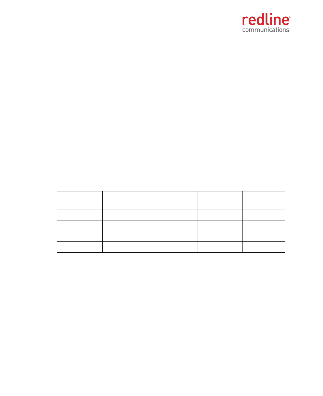
RDL-3000 M2M Solutions
70-00184-03-02 Proprietary Redline Communications © 2013 Page 31 of 50 April 30, 2013
4.2 RDL-3000-RME
4.2.1 RDL-3000-RME Frequency Bands
Operation of the final product (containing the RDL-3000-RME module) requires a
software 'key' that is available exclusively from Redline. This key restricts device
operation to the IC 2305-2320 MHz and 2345-2360 MHz bands and is subject to
licensing. The professional installer and operator can not modify or otherwise circumvent
these operational restrictions.
4.2.2 RDL-3000-RME Antenna Use and Transmit Power
The RDL-3000-RME module supports operation with 2x2 MIMO antenna systems with
two transmit chains and two receive chains. The RDL-3000-RME module must be used
only with certified antennas and using the channel size and output power level specified
by the IC regulations.
4.2.3 RDL-3000-RME Certified Antennas
The RDL-3000-RME module has been designed to operate with the antennas listed in
the following table.
Table 65: RDL-3000-RME: Approved Antennas
Manufacturer
Part #
Gain
(dBi)
Beamwidth
(degrees)
Frequency
Range
(MHz)
Redline
30-00328-30
14.5
35
2300 - 2700
Redline
AFS-DBG-02120-01
15
120
2300-2700
Redline
AFS-DBG-0290-01
16
90
2300-2700
Redline
AFS-DBG-0260-01
17
60
2300-2700
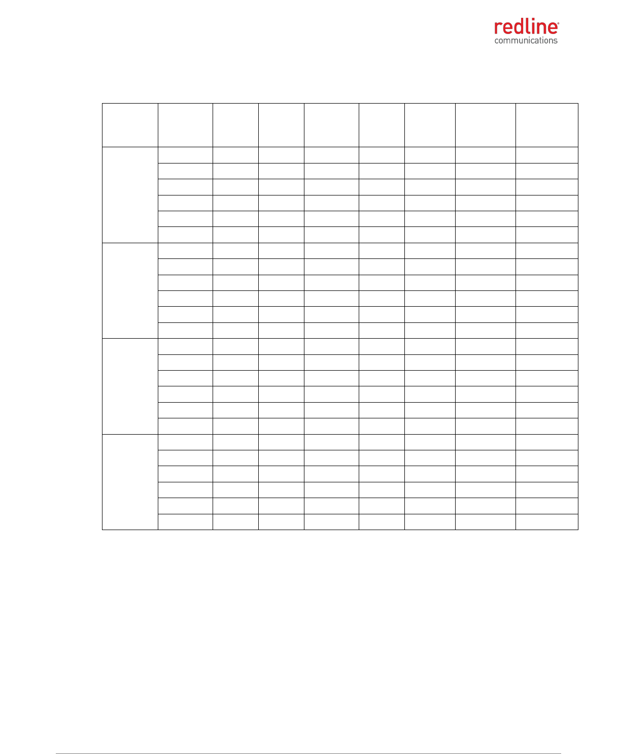
RDL-3000-RMC/E/F PRODUCT MANUAL
70-00184-03-02 Proprietary Redline Communications © 2013 Page 32 of 50 April 30, 2013
4.2.4 RDL-3000-RME Power & EIRP (MIMO Operation)
Table 66: 2.5 GHz: RF Power & EIRP: 5 MHz channel for 14.5 dBi antenna for IC
Modulation
Frequency
(MHz)
Power at
RF-1
(dBm)
Power at
RF-2
(dBm)
Combined
output
power
(dBm)
Antenna
gain
(dBi)
EIRP
(dBm)
EIRP limit
(dBm)
EIRP margin
(dB)
BPSK
2348
13.57
13.75
16.67
14.50
31.17
63.00
31.83
2352.5
23.62
23.95
26.80
14.50
41.30
63.00
21.70
2357.5
28.93
29.43
32.20
14.50
46.70
63.00
16.30
2308
29.23
29.41
32.33
14.50
46.83
63.00
16.17
2312.5
23.37
24.19
26.81
14.50
41.31
63.00
21.69
2317
16.88
14.73
18.95
14.50
33.45
63.00
29.55
QPSK
2348
13.29
13.62
16.47
14.50
30.97
63.00
32.03
2352.5
23.47
23.82
26.66
14.50
41.16
63.00
21.84
2357.5
28.87
29.52
32.22
14.50
46.72
63.00
16.28
2308
29.29
29.47
32.39
14.50
46.89
63.00
16.11
2312.5
23.18
24.02
26.63
14.50
41.13
63.00
21.87
2317
17.11
14.89
19.15
14.50
33.65
63.00
29.35
16-QAM
2348
13.45
13.59
16.53
14.50
31.03
63.00
31.97
2352.5
23.59
23.87
26.74
14.50
41.24
63.00
21.76
2357.5
28.91
29.29
32.11
14.50
46.61
63.00
16.39
2308
29.12
29.52
32.33
14.50
46.83
63.00
16.17
2312.5
23.52
24.59
27.10
14.50
41.60
63.00
21.40
2317
16.92
14.48
18.88
14.50
33.38
63.00
29.62
64-QAM
2348
13.45
13.78
16.63
14.50
31.13
63.00
31.87
2352.5
23.65
23.27
26.47
14.50
40.97
63.00
22.03
2357.5
28.79
29.39
32.11
14.50
46.61
63.00
16.39
2308
29.38
29.28
32.34
14.50
46.84
63.00
16.16
2312.5
23.21
24.19
26.74
14.50
41.24
63.00
21.76
2317
17.19
15.28
19.35
14.50
33.85
63.00
29.15
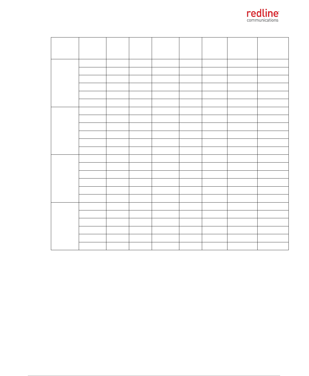
RDL-3000-RMC/E/F PRODUCT MANUAL
70-00184-03-02 Proprietary Redline Communications © 2013 Page 33 of 50 April 30, 2013
Table 67: 2.5 GHz: RF Power & EIRP: 5 MHz channel for 15 dBi antenna for IC
Modulation
Frequency
(MHz)
Power at
RF-1
(dBm)
Power at
RF-2
(dBm)
Combined
output
power
(dBm)
Antenna
gain
(dBi)
EIRP
(dBm)
EIRP limit
(dBm)
EIRP margin
(dB)
BPSK
2348
13.57
13.75
16.67
15.00
31.67
63.00
31.33
2352.5
23.62
23.95
26.80
15.00
41.80
63.00
21.20
2357.5
28.93
29.43
32.20
15.00
47.20
63.00
15.80
2308
29.23
29.41
32.33
15.00
47.33
63.00
15.67
2312.5
23.37
24.19
26.81
15.00
41.81
63.00
21.19
2317
16.88
14.73
18.95
15.00
33.95
63.00
29.05
QPSK
2348
13.29
13.62
16.47
15.00
31.47
63.00
31.53
2352.5
23.47
23.82
26.66
15.00
41.66
63.00
21.34
2357.5
28.87
29.52
32.22
15.00
47.22
63.00
15.78
2308
29.29
29.47
32.39
15.00
47.39
63.00
15.61
2312.5
23.18
24.02
26.63
15.00
41.63
63.00
21.37
2317
17.11
14.89
19.15
15.00
34.15
63.00
28.85
16-QAM
2348
13.45
13.59
16.53
15.00
31.53
63.00
31.47
2352.5
23.59
23.87
26.74
15.00
41.74
63.00
21.26
2357.5
28.91
29.29
32.11
15.00
47.11
63.00
15.89
2308
29.12
29.52
32.33
15.00
47.33
63.00
15.67
2312.5
23.52
24.59
27.10
15.00
42.10
63.00
20.90
2317
16.92
14.48
18.88
15.00
33.88
63.00
29.12
64-QAM
2348
13.45
13.78
16.63
15.00
31.63
63.00
31.37
2352.5
23.65
23.27
26.47
15.00
41.47
63.00
21.53
2357.5
28.79
29.39
32.11
15.00
47.11
63.00
15.89
2308
29.38
29.28
32.34
15.00
47.34
63.00
15.66
2312.5
23.21
24.19
26.74
15.00
41.74
63.00
21.26
2317
17.19
15.28
19.35
15.00
34.35
63.00
28.65
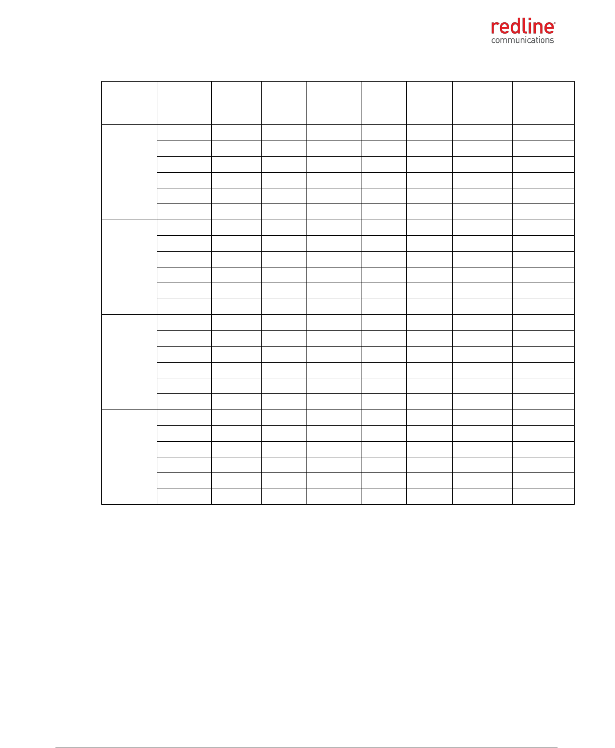
RDL-3000-RMC/E/F PRODUCT MANUAL
70-00184-03-02 Proprietary Redline Communications © 2013 Page 34 of 50 April 30, 2013
Table 68: 2.5 GHz: RF Power & EIRP: 5 MHz channel for 16 dBi antenna for IC
Modulation
Frequency
(MHz)
Power at
RF-1
(dBm)
Power at
RF-2
(dBm)
Combined
output
power
(dBm)
Antenna
gain
(dBi)
EIRP
(dBm)
EIRP limit
(dBm)
EIRP margin
(dB)
BPSK
2348
13.57
13.75
16.67
16.00
32.67
63.00
30.33
2352.5
23.62
23.95
26.80
16.00
42.80
63.00
20.20
2357.5
28.93
29.43
32.20
16.00
48.20
63.00
14.80
2308
29.23
29.41
32.33
16.00
48.33
63.00
14.67
2312.5
23.37
24.19
26.81
16.00
42.81
63.00
20.19
2317
16.88
14.73
18.95
16.00
34.95
63.00
28.05
QPSK
2348
13.29
13.62
16.47
16.00
32.47
63.00
30.53
2352.5
23.47
23.82
26.66
16.00
42.66
63.00
20.34
2357.5
28.87
29.52
32.22
16.00
48.22
63.00
14.78
2308
29.29
29.47
32.39
16.00
48.39
63.00
14.61
2312.5
23.18
24.02
26.63
16.00
42.63
63.00
20.37
2317
17.11
14.89
19.15
16.00
35.15
63.00
27.85
16-QAM
2348
13.45
13.59
16.53
16.00
32.53
63.00
30.47
2352.5
23.59
23.87
26.74
16.00
42.74
63.00
20.26
2357.5
28.91
29.29
32.11
16.00
48.11
63.00
14.89
2308
29.12
29.52
32.33
16.00
48.33
63.00
14.67
2312.5
23.52
24.59
27.10
16.00
43.10
63.00
19.90
2317
16.92
14.48
18.88
16.00
34.88
63.00
28.12
64-QAM
2348
13.45
13.78
16.63
16.00
32.63
63.00
30.37
2352.5
23.65
23.27
26.47
16.00
42.47
63.00
20.53
2357.5
28.79
29.39
32.11
16.00
48.11
63.00
14.89
2308
29.38
29.28
32.34
16.00
48.34
63.00
14.66
2312.5
23.21
24.19
26.74
16.00
42.74
63.00
20.26
2317
17.19
15.28
19.35
16.00
35.35
63.00
27.65

RDL-3000-RMC/E/F PRODUCT MANUAL
70-00184-03-02 Proprietary Redline Communications © 2013 Page 35 of 50 April 30, 2013
Table 69: 2.5 GHz: RF Power & EIRP: 5 MHz channel for 17 dBi antenna for IC
Modulation
Frequency
(MHz)
Power at
RF-1
(dBm)
Power at
RF-2
(dBm)
Combined
output
power
(dBm)
Antenna
gain
(dBi)
EIRP
(dBm)
EIRP limit
(dBm)
EIRP margin
(dB)
BPSK
2348
13.57
13.75
16.67
17.00
33.67
63.00
29.33
2352.5
23.62
23.95
26.80
17.00
43.80
63.00
19.20
2357.5
28.93
29.43
32.20
17.00
49.20
63.00
13.80
2308
29.23
29.41
32.33
17.00
49.33
63.00
13.67
2312.5
23.37
24.19
26.81
17.00
43.81
63.00
19.19
2317
16.88
14.73
18.95
17.00
35.95
63.00
27.05
QPSK
2348
13.29
13.62
16.47
17.00
33.47
63.00
29.53
2352.5
23.47
23.82
26.66
17.00
43.66
63.00
19.34
2357.5
28.87
29.52
32.22
17.00
49.22
63.00
13.78
2308
29.29
29.47
32.39
17.00
49.39
63.00
13.61
2312.5
23.18
24.02
26.63
17.00
43.63
63.00
19.37
2317
17.11
14.89
19.15
17.00
36.15
63.00
26.85
16-QAM
2348
13.45
13.59
16.53
17.00
33.53
63.00
29.47
2352.5
23.59
23.87
26.74
17.00
43.74
63.00
19.26
2357.5
28.91
29.29
32.11
17.00
49.11
63.00
13.89
2308
29.12
29.52
32.33
17.00
49.33
63.00
13.67
2312.5
23.52
24.59
27.10
17.00
44.10
63.00
18.90
2317
16.92
14.48
18.88
17.00
35.88
63.00
27.12
64-QAM
2348
13.45
13.78
16.63
17.00
33.63
63.00
29.37
2352.5
23.65
23.27
26.47
17.00
43.47
63.00
19.53
2357.5
28.79
29.39
32.11
17.00
49.11
63.00
13.89
2308
29.38
29.28
32.34
17.00
49.34
63.00
13.66
2312.5
23.21
24.19
26.74
17.00
43.74
63.00
19.26
2317
17.19
15.28
19.35
17.00
36.35
63.00
26.65

RDL-3000-RMC/E/F PRODUCT MANUAL
70-00184-03-02 Proprietary Redline Communications © 2013 Page 36 of 50 April 30, 2013
Table 70: 2.5 GHz: RF Power & EIRP: 10 MHz channel for 14.5 dBi antenna for IC
Modulation
Frequency
(MHz)
Power at
RF-1
(dBm)
Power at
RF-2
(dBm)
Combined
output
power
(dBm)
Antenna
gain
(dBi)
EIRP
(dBm)
EIRP limit
(dBm)
EIRP margin
(dB)
BPSK
2350.5
12.3
12.95
15.65
14.50
30.15
63.00
32.85
2355
19.3
19.89
22.62
14.50
37.12
63.00
25.88
2310
19.8
18.61
22.27
14.50
36.77
63.00
26.23
2314.5
13.3
12.75
16.04
14.50
30.54
63.00
32.46
QPSK
2350.5
12.3
12.78
15.55
14.50
30.05
63.00
32.95
2355
19.2
19.92
22.58
14.50
37.08
63.00
25.92
2310
19.9
18.59
22.32
14.50
36.82
63.00
26.18
2314.5
13.3
12.69
16.01
14.50
30.51
63.00
32.49
16-QAM
2350.5
12.3
12.91
15.62
14.50
30.12
63.00
32.88
2355
19.3
19.97
22.64
14.50
37.14
63.00
25.86
2310
19.8
18.59
22.24
14.50
36.74
63.00
26.26
2314.5
13.5
12.82
16.16
14.50
30.66
63.00
32.34
64-QAM
2350.5
12.3
12.87
15.60
14.50
30.10
63.00
32.90
2355
19.4
19.92
22.68
14.50
37.18
63.00
25.82
2310
19.9
18.59
22.29
14.50
36.79
63.00
26.21
2314.5
13.4
12.82
16.10
14.50
30.60
63.00
32.40

RDL-3000-RMC/E/F PRODUCT MANUAL
70-00184-03-02 Proprietary Redline Communications © 2013 Page 37 of 50 April 30, 2013
Table 71: 2.5 GHz: RF Power & EIRP: 10 MHz channel for 15 dBi antenna for IC
Modulation
Frequency
(MHz)
Power at
RF-1
(dBm)
Power at
RF-2
(dBm)
Combined
output
power
(dBm)
Antenna
gain
(dBi)
EIRP
(dBm)
EIRP limit
(dBm)
EIRP margin
(dB)
BPSK
2350.5
12.3
12.95
15.65
15.00
30.65
63.00
32.35
2355
19.3
19.89
22.62
15.00
37.62
63.00
25.38
2310
19.8
18.61
22.27
15.00
37.27
63.00
25.73
2314.5
13.3
12.75
16.04
15.00
31.04
63.00
31.96
QPSK
2350.5
12.3
12.78
15.55
15.00
30.55
63.00
32.45
2355
19.2
19.92
22.58
15.00
37.58
63.00
25.42
2310
19.9
18.59
22.32
15.00
37.32
63.00
25.68
2314.5
13.3
12.69
16.01
15.00
31.01
63.00
31.99
16-QAM
2350.5
12.3
12.91
15.62
15.00
30.62
63.00
32.38
2355
19.3
19.97
22.64
15.00
37.64
63.00
25.36
2310
19.8
18.59
22.24
15.00
37.24
63.00
25.76
2314.5
13.5
12.82
16.16
15.00
31.16
63.00
31.84
64-QAM
2350.5
12.3
12.87
15.60
15.00
30.60
63.00
32.40
2355
19.4
19.92
22.68
15.00
37.68
63.00
25.32
2310
19.9
18.59
22.29
15.00
37.29
63.00
25.71
2314.5
13.4
12.82
16.10
15.00
31.10
63.00
31.90
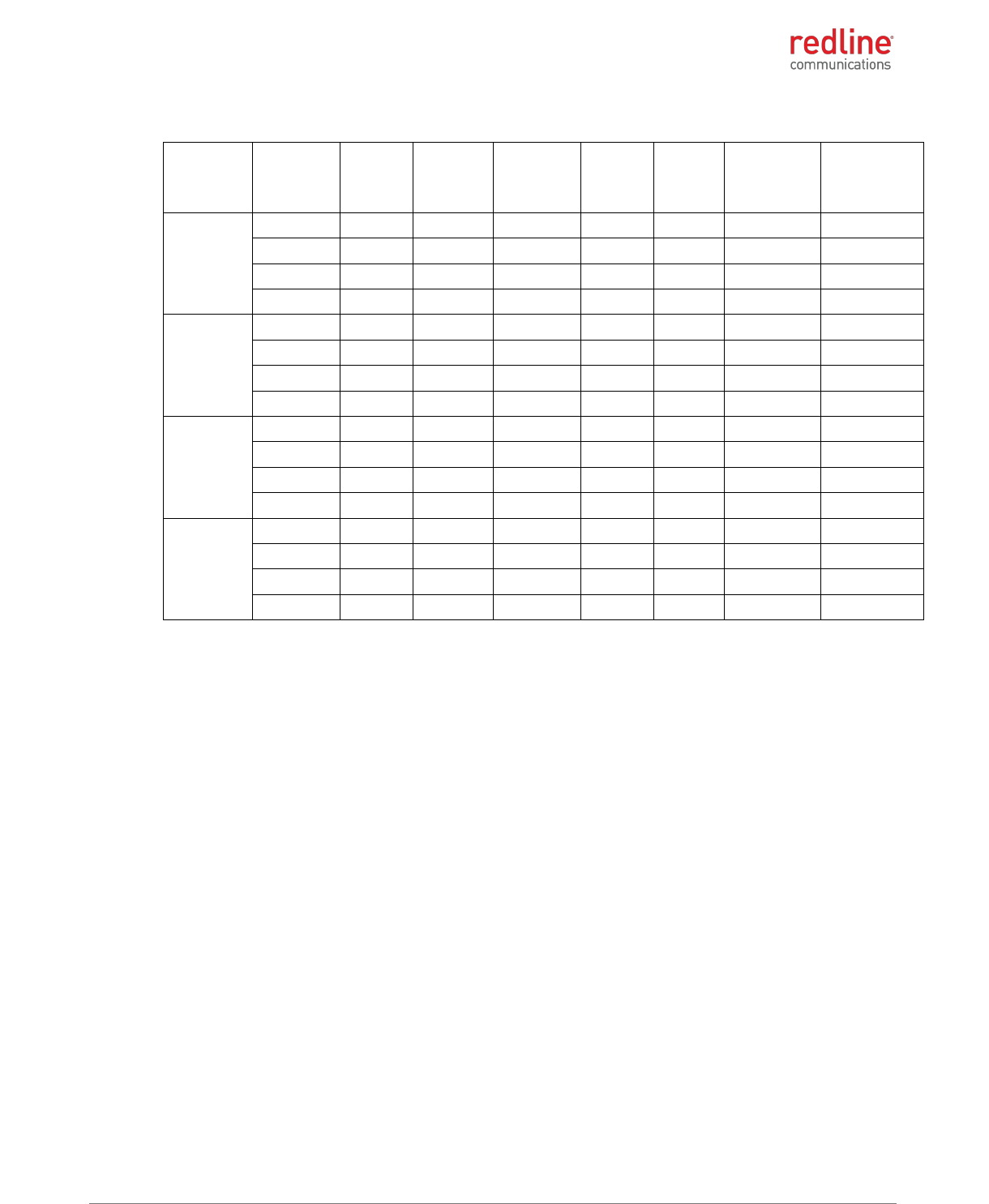
RDL-3000-RMC/E/F PRODUCT MANUAL
70-00184-03-02 Proprietary Redline Communications © 2013 Page 38 of 50 April 30, 2013
Table 72: 2.5 GHz: RF Power & EIRP: 10 MHz channel for 16 dBi antenna for IC
Modulation
Frequency
(MHz)
Power at
RF-1
(dBm)
Power at
RF-2
(dBm)
Combined
output
power
(dBm)
Antenna
gain
(dBi)
EIRP
(dBm)
EIRP limit
(dBm)
EIRP margin
(dB)
BPSK
2350.5
12.3
12.95
15.65
16.00
31.65
63.00
31.35
2355
19.3
19.89
22.62
16.00
38.62
63.00
24.38
2310
19.8
18.61
22.27
16.00
38.27
63.00
24.73
2314.5
13.3
12.75
16.04
16.00
32.04
63.00
30.96
QPSK
2350.5
12.3
12.78
15.55
16.00
31.55
63.00
31.45
2355
19.2
19.92
22.58
16.00
38.58
63.00
24.42
2310
19.9
18.59
22.32
16.00
38.32
63.00
24.68
2314.5
13.3
12.69
16.01
16.00
32.01
63.00
30.99
16-QAM
2350.5
12.3
12.91
15.62
16.00
31.62
63.00
31.38
2355
19.3
19.97
22.64
16.00
38.64
63.00
24.36
2310
19.8
18.59
22.24
16.00
38.24
63.00
24.76
2314.5
13.5
12.82
16.16
16.00
32.16
63.00
30.84
64-QAM
2350.5
12.3
12.87
15.60
16.00
31.60
63.00
31.40
2355
19.4
19.92
22.68
16.00
38.68
63.00
24.32
2310
19.9
18.59
22.29
16.00
38.29
63.00
24.71
2314.5
13.4
12.82
16.10
16.00
32.10
63.00
30.90
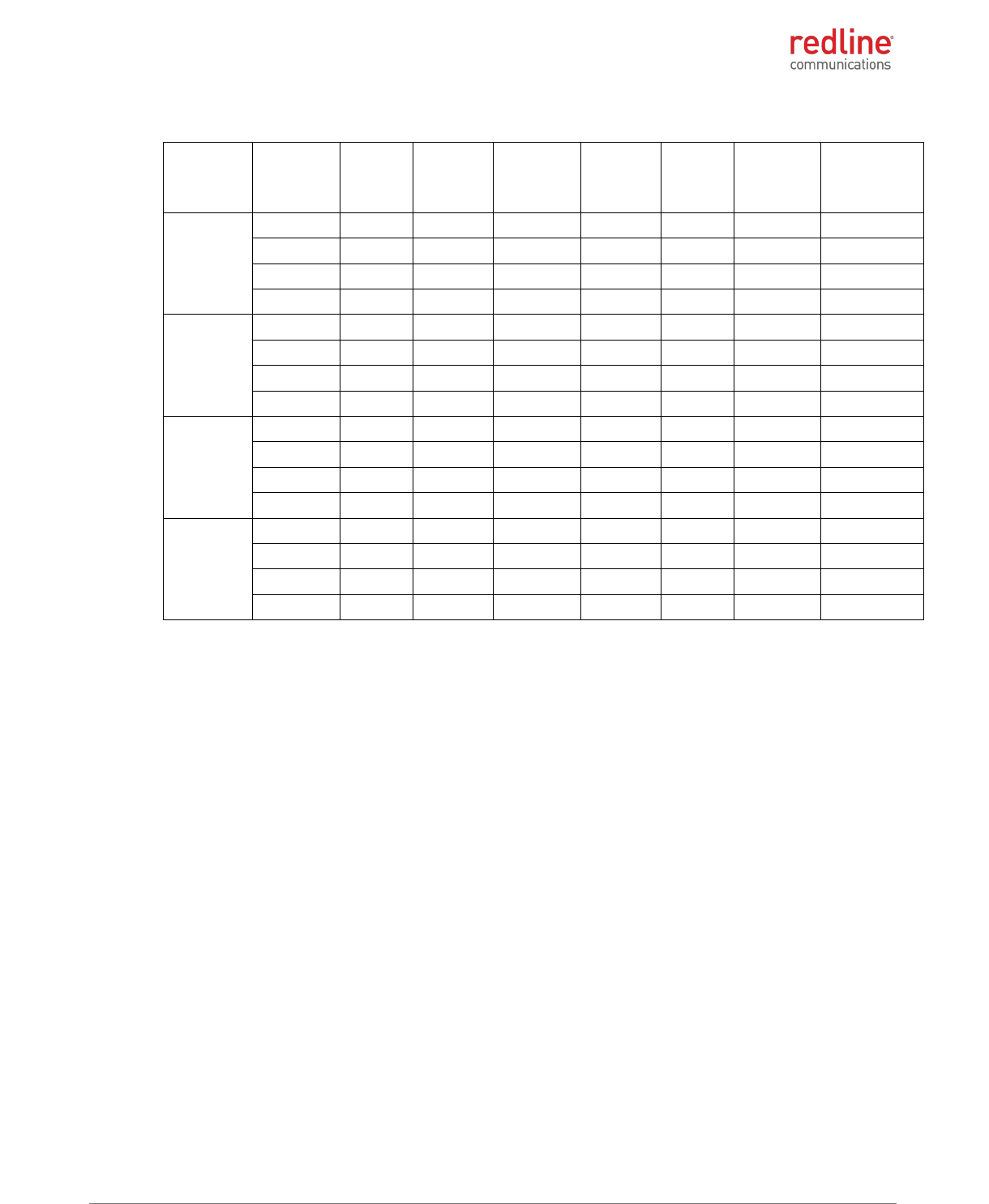
RDL-3000-RMC/E/F PRODUCT MANUAL
70-00184-03-02 Proprietary Redline Communications © 2013 Page 39 of 50 April 30, 2013
Table 73: 2.5 GHz: RF Power & EIRP: 10 MHz channel for 17 dBi antenna for IC
Modulation
Frequency
(MHz)
Power at
RF-1
(dBm)
Power at
RF-2
(dBm)
Combined
output
power
(dBm)
Antenna
gain (dBi)
EIRP
(dBm)
EIRP limit
(dBm)
EIRP margin
(dB)
BPSK
2350.5
12.3
12.95
15.65
17.00
32.65
63.00
30.35
2355
19.3
19.89
22.62
17.00
39.62
63.00
23.38
2310
19.8
18.61
22.27
17.00
39.27
63.00
23.73
2314.5
13.3
12.75
16.04
17.00
33.04
63.00
29.96
QPSK
2350.5
12.3
12.78
15.55
17.00
32.55
63.00
30.45
2355
19.2
19.92
22.58
17.00
39.58
63.00
23.42
2310
19.9
18.59
22.32
17.00
39.32
63.00
23.68
2314.5
13.3
12.69
16.01
17.00
33.01
63.00
29.99
16-QAM
2350.5
12.3
12.91
15.62
17.00
32.62
63.00
30.38
2355
19.3
19.97
22.64
17.00
39.64
63.00
23.36
2310
19.8
18.59
22.24
17.00
39.24
63.00
23.76
2314.5
13.5
12.82
16.16
17.00
33.16
63.00
29.84
64-QAM
2350.5
12.3
12.87
15.60
17.00
32.60
63.00
30.40
2355
19.4
19.92
22.68
17.00
39.68
63.00
23.32
2310
19.9
18.59
22.29
17.00
39.29
63.00
23.71
2314.5
13.4
12.82
16.10
17.00
33.10
63.00
29.90
RDL-3000-RMC/E/F PRODUCT MANUAL
70-00184-03-02 Proprietary Redline Communications © 2013 Page 40 of 50 April 30, 2013
4.3 RDL-3000-RMF
4.3.1 RDL-3000-RMF Frequency Bands
Operation of the final product (containing the RDL-3000-RMF module) requires a
software 'key' that is available exclusively from Redline. This key restricts device
operation to the FCC 473 - 695 MHz band on TV channels 14 - 35 and 39 - 51. The
professional installer and operator can not modify or otherwise circumvent these
operational restrictions.
To operate in the TV Whitespaces frequency range, each RDL-3000-RMF must contact
and register with the WSDB database server (server URL is programmed into the RDL-
3000-RMF). The RDL-3000 may only transmit on channels indicated as 'available' by the
WSDB database. Channel assignments are temporary and the RDL-3000-RMF must
periodically contact the WSDB to refresh the channel list. The RDL-3000-RMF vacates a
channel in-use immediately when a WSDB database status update indicates the channel
is no longer available or the expiry time for an obtained list has elapsed.
The RDL-3000-RMF operating as a PMP Sector Controller/PTP Master (PMP-SC) is not
allowed to transmit on any channel before registering with the WSDB database and
obtaining a list of available channels for its location. The RDL-3000-RMF operating as a
PMP Subscriber/PTP Slave (PMP-SS) is allowed to transmit on the channel currently
being used by the PMP-SC initially only for the purpose of registering with the WSDB
database and obtaining a list of available channels for its location. If the channel in-use
is not available, the PMP-SS notifies the PMP-SC and stops transmitting. The PMP-SS
may register and obtain the current channel list once per hour.
4.3.2 RDL-3000-RMF Antenna Use and Transmit Power
The RDL-3000-RMF module supports operation with 2x2 MIMO antenna systems with
two transmit chains and two receive chains. The RDL-3000-RMF module must be used
only with certified antennas and using the channel size and output power level specified
by the FCC regulations.
Table 74: RDL-3000-RMF: Transmit Power
Channel #
Tx Power (dBm)
14-34
40-51
+18
35, 39
+16
4.3.3 RDL-3000-RMF Certified Antennas
This device has been designed to operate with the antennas listed in the following table.
Any additional antennas will be used only after authorization is obtained through Class II
permissive change.
Table 75: RDL-3000-RMF: Approved Antennas
Supplier
Part #
Gain
(dBi)
Frequency
Range (MHz)
Application
Size
Beamwidth /
Polarity
Redline
AFS-VH-
60060-01
13
470-698
Sector
122 cm
(48 in)
60 deg
vpol & hpol
Redline
AFS-SB-
60055-01
11
470-698
Log-P
Directional
122 cm
(48 in)
55 deg
vpol & hpol
RDL-3000-RMC/E/F PRODUCT MANUAL
70-00184-03-02 Proprietary Redline Communications © 2013 Page 41 of 50 April 30, 2013
5 Regulatory Notices
5.1 FCC Notices: Deployment in USA
5.1.1 RDL-3000-RMC
The following notices about deployment in the USA are included in training and
documentation provided to professional installers and operators of the final product:
1. The final product must be professionally installed.
2. WARNING -- FCC RF Exposure Warnings
To satisfy FCC RF exposure requirements for RF transmitting devices, the following
distances should be maintained between the antenna of this device and persons
during device operation:
Table 76: FCC: RDL-3000-RMC Recommended Safe Distances
Frequency (MHz)
Deployment
Separation Distance
4900
PMP
260 cm (103") or more
5300
PMP
20 cm (7.8") or more
5400
PMP
20 cm (7.8") or more
5800
PMP
20 cm (7.8") or more
To ensure compliance, operation at closer than these distances is not
recommended. The antenna used for this transmitter must not be collocated in
conjunction with any other antenna or transmitter.
3. FCC Information to Users @ FCC 15.105:
NOTE: This equipment has been tested and found to comply with the limits for a
Class B digital device, pursuant to part 15 of the FCC Rules. These limits are
designed to provide reasonable protection against harmful interference in a
residential installation.
This equipment generates uses and can radiate radio frequency energy and, if not
installed and used in accordance with the instructions, may cause harmful
interference to radio communications. However, there is no guarantee that
interference will not occur in a particular installation. If this equipment does cause
harmful interference to radio or television reception, which can be determined by
turning the equipment off and on, the user is encouraged to try to correct the
interference by one or more of the following measures:
- Reorient or relocate the receiving antenna.
- Increase the separation between the equipment and receiver.
- Connect the equipment into an outlet on a circuit different from that to which the
receiver is connected.
- Consult the dealer or an experienced radio/TV technician for help.
Where DFS is required by regional regulations, this function is permanently enabled
at the factory and can not be disabled by the installer or end-user.
4. FCC Information to Users @ FCC 15.19:
This device complies with Part 15 of the FCC Rules. Operation is subject to the following
two conditions:
(1) This device may not cause harmful interference.
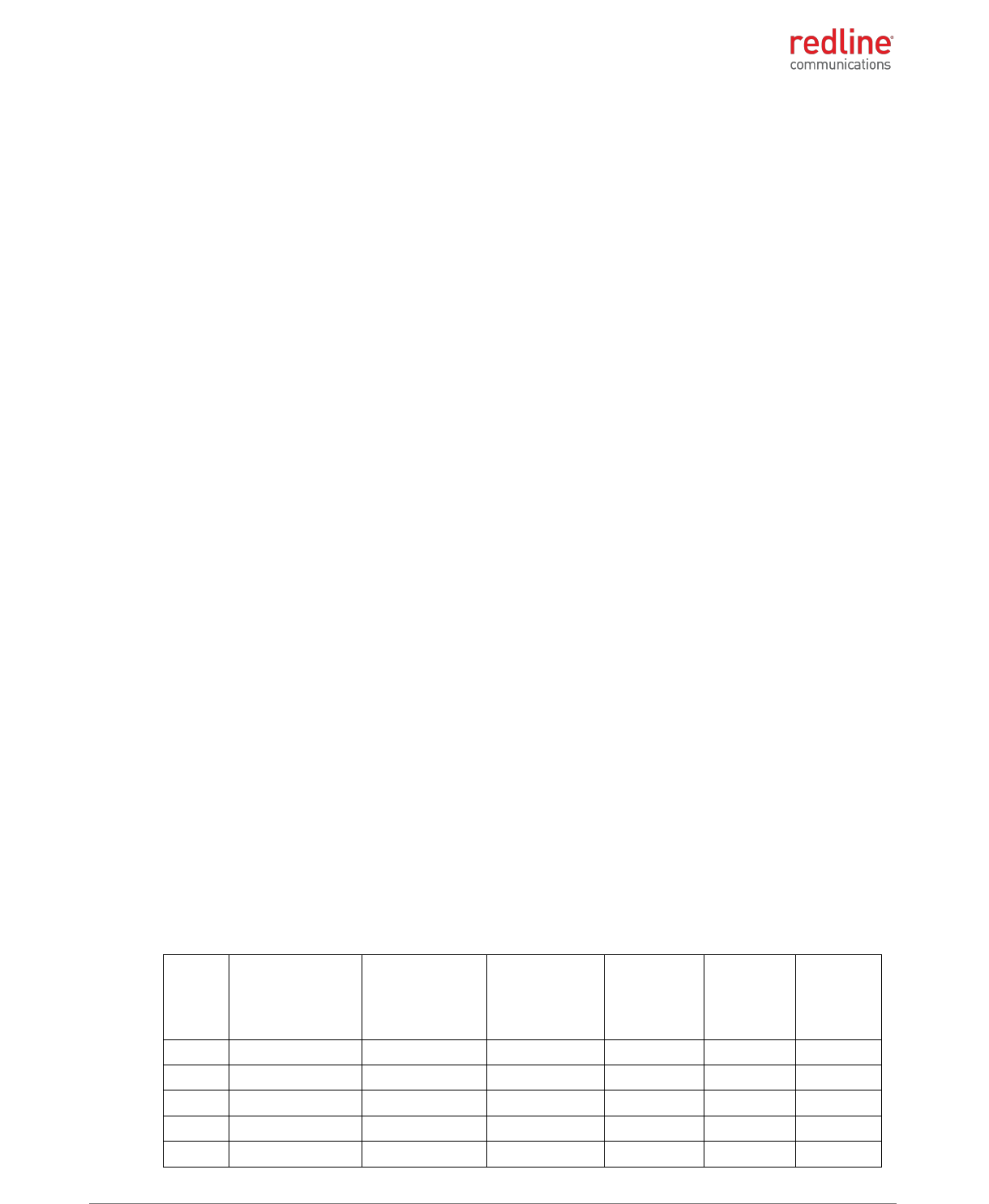
RDL-3000-RMC/E/F PRODUCT MANUAL
70-00184-03-02 Proprietary Redline Communications © 2013 Page 42 of 50 April 30, 2013
(2) This device must accept any interference received, including interference that
may cause undesired operation.
5. FCC Information to Users @ FCC 15.21:
Warning: Changes or modifications not expressly approved by Redline
Communications could void the user’s authority to operate the equipment.
FCC Recommendations to UNII band Users
Redline, in complete cooperation with the FCC, instructs professional installers and
operators of this equipment in the UNII band to follow these guidelines.
Review Table 3: Notice - FCC - TDWR System Locations to determine if the intended
deployment location is near a TDWR site.
1. Operation in the TDWR band of 5600-5650 MHz is not permitted. The equipment
does not allow the operator to use Web, CLI, or SNMP to set a frequency that
overlaps this range.
2. Operation in the 5570-5680 MHz band (excluding 5600-5650 MHz) is permitted
beyond 35 km (22 mi) AND not in line-of-sight of a TDWR site.
3. Operation in the 5570-5680 MHz band (excluding 5600-5650 MHz) within 35 km (22
mi) OR in line-of-sight of a TDWR site is allowed by observing a 30 MHz upper and
lower guard band on the operational frequency of the nearby TWDR station.
For example, if the nearby TDWR is Miami (5605 MHz), the base station frequency
setting must exclude channels with center frequencies from 5575 MHz (30 MHz
below 5605) to 5635 MHz (30 MHz above 5605).
It is recommended that the operator register in the voluntary WISPA sponsored
database. Go to the www.wispa.org website and click on TDWR to view more
information and register in the online database.
Frequency selection is regulated by a regional code integrated into each options key.
This feature enforces compliance to regional regulatory statutes. Each options key is
keyed to the unique MAC address of an RDL-3000 radio platform. Options keys can be
generated only by Redline and its authorized agents. End-users can not generate or
modify options keys (to obtain or alter regional codes).
Redline provides technical training programs and information covering network design
and installation for Redline distributors, value added resellers, installers, and other
partners. This program is intended in part to train participants to a level of understanding
where they are competent to order, setup and configure the Redline wireless equipment
to be in compliance with regulatory requirements in the region where this equipment is
installed. Redline sales order processing is also trained to verify that regional codes are
consistent with the intended deployment location as documented in the sales order.
Table 77: FCC: RDL-3000-RMC TDWR System Locations
STATE
CITY
LONGITUDE
LATITUDE
FREQUENCY
TERRAIN
ELEVATION
(MSL) [ft]
ANTENNA
HEIGHT
ABOVE
TERRAIN
[ft]
AZ
PHOENIX
W 112 09 46
N 33 25 14
5610 MHz
1024
64
CO
DENVER
W 104 31 35
N 39 43 39
5615 MHz
5643
64
FL
FT LAUDERDALE
W 080 20 39
N 26 08 36
5645 MHz
7
113
FL
MIAMI
W 080 29 28
N 25 45 27
5605 MHz
10
113
FL
ORLANDO
W 081 19 33
N 28 20 37
5640 MHz
72
97
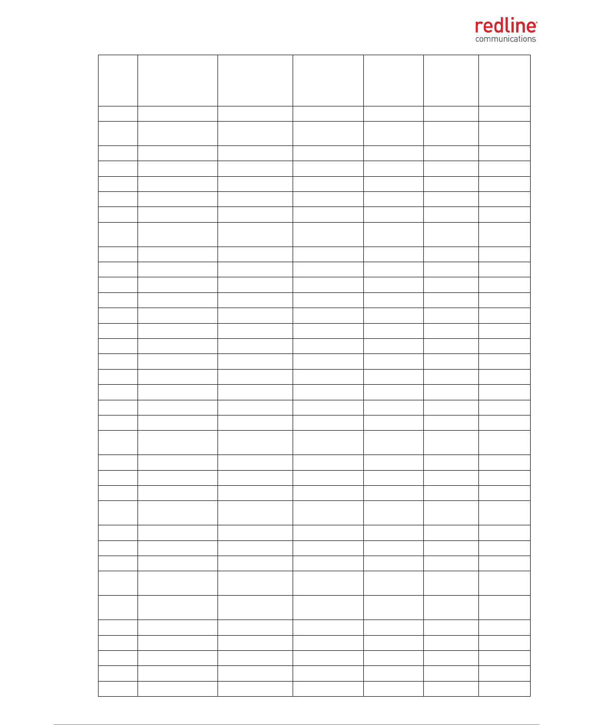
RDL-3000-RMC/E/F PRODUCT MANUAL
70-00184-03-02 Proprietary Redline Communications © 2013 Page 43 of 50 April 30, 2013
STATE
CITY
LONGITUDE
LATITUDE
FREQUENCY
TERRAIN
ELEVATION
(MSL) [ft]
ANTENNA
HEIGHT
ABOVE
TERRAIN
[ft]
FL
TAMPA
W 082 31 04
N 27 51 35
5620 MHz
14
80
FL
WEST PALM
BEACH
W 080 16 23
N 26 41 17
5615 MHz
20
113
GA
ATLANTA
W 084 15 44
N 33 38 48
5615 MHz
962
113
IL
MCCOOK
W 087 51 31
N 41 47 50
5615 MHz
646
97
IL
CRESTWOOD
W 087 43 47
N 41 39 05
5645 MHz
663
113
IN
INDIANAPOLIS
W 086 26 08
N 39 38 14
5605 MHz
751
97
KS
WICHITA
W 097 26 13
N 37 30 26
5603 MHz
1270
80
KY
COVINGTON
CINCINNATI
W 084 34 48
N 38 53 53
5610 MHz
942
97
KY
LOUISVILLE
W 085 36 38
N 38 02 45
5646 MHz
617
113
LA
NEW ORLEANS
W 090 24 11
N 30 01 18
5645 MHz
2
97
MA
BOSTON
W 070 56 01
N 42 09 30
5610 MHz
151
113
MD
BRANDYWINE
W 076 50 42
N 38 41 43
5635 MHz
233
113
MD
BENFIELD
W 076 37 48
N 39 05 23
5645 MHz
184
113
MD
CLINTON
W 076 57 43
N 38 45 32
5615 MHz
249
97
MI
DETROIT
W 083 30 54
N 42 06 40
5615 MHz
656
113
MN
MINNEAPOLIS
W 092 55 58
N 44 52 17
5610 MHz
1040
80
MO
KANSAS CITY
W 094 44 31
N 39 29 55
5605 MHz
1040
64
MO
SAINT LOUIS
W 090 29 21
N 38 48 20
5610 MHz
551
97
MS
DESOTO COUNTY
W 089 59 33
N 34 53 45
5610 MHz
371
113
NC
CHARLOTTE
W 080 53 06
N 35 21 39
5608 MHz
807
113
NC
RALEIGH
DURHAM
W 078 41 50
N 36 00 07
5647 MHz
400
113
NJ
WOODBRIDGE
W 074 16 13
N 40 35 37
5620 MHz
19
113
NJ
PENNSAUKEN
W 075 04 12
N 39 56 57
5610 MHz
39
113
NV
LAS VEGAS
W 115 00 26
N 36 08 37
5645 MHz
1995
64
NY
FLOYD BENNETT
FIELD
W 073 52 49
N 40 35 20
5647 MHz
8
97
OH
DAYTON
W 084 07 23
N 40 01 19
5640 MHz
922
97
OH
CLEVELAND
W 082 00 28
N 41 17 23
5645 MHz
817
113
OH
COLUMBUS
W 082 42 55
N 40 00 20
5605 MHz
1037
113
OK
AERO. CTR TDWR
#1
W 097 37 31
N 35 24 19
5610 MHz
1285
80
OK
AERO. CTR TDWR
#2
W 097 37 43
N 35 23 34
5620 MHz
1293
97
OK
TULSA
W 095 49 34
N 36 04 14
5605 MHz
712
113
OK
OKLAHOMA CITY
W 097 30 36
N 35 16 34
5603 MHz
1195
64
PA
HANOVER
W 080 29 10
N 40 30 05
5615 MHz
1266
113
PR
SAN JUAN
W 066 10 46
N 18 28 26
5610 MHz
59
113
TN
NASHVILLE
W 086 39 42
N 35 58 47
5605 MHz
722
97
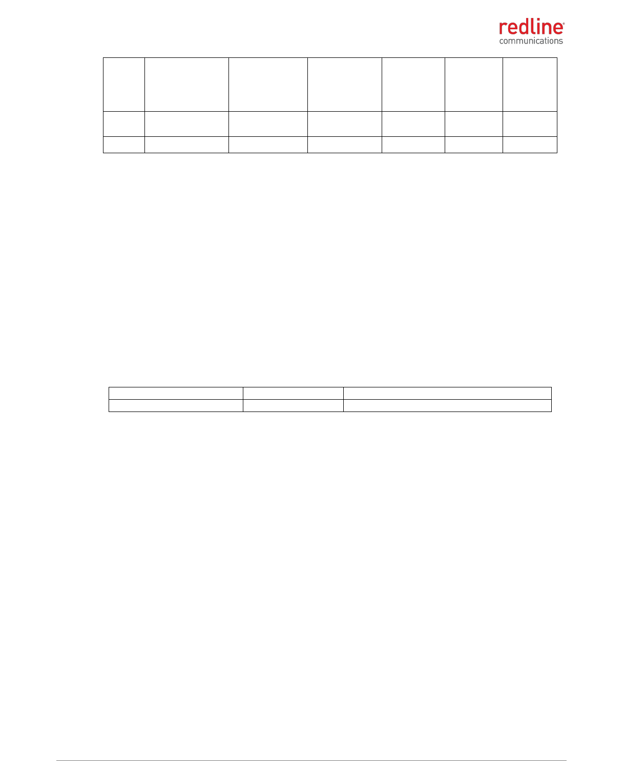
RDL-3000-RMC/E/F PRODUCT MANUAL
70-00184-03-02 Proprietary Redline Communications © 2013 Page 44 of 50 April 30, 2013
STATE
CITY
LONGITUDE
LATITUDE
FREQUENCY
TERRAIN
ELEVATION
(MSL) [ft]
ANTENNA
HEIGHT
ABOVE
TERRAIN
[ft]
TX
HOUSTON
INTERCONTL
W 095 34 01
N 30 03 54
5605 MHz
154
97
TX
PEARLAND
W 095 14 30
N 29 30 59
5645 MHz
36
80
Additional information:
http://spectrumbridge.com/udrs/home.aspx
http://www.wispa.org/?page_id=2341
5.1.2 RDL-3000-RMF
The following notices about deployment in the USA are included in training and
documentation provided to professional installers and operators of the final product:
1. The final product must be professionally installed.
2. WARNING -- FCC RF Exposure Warnings
To satisfy FCC RF exposure requirements for RF transmitting devices, the following
distances should be maintained between the antenna of this device and persons
during device operation:
Table 78: FCC: RDL-3000-RME/F Recommended Safe Distances
Frequency (MHz)
Deployment
Separation Distance
470 - 698
PMP
40 cm (15 3/4") or more
To ensure compliance, operation at closer than these distances is not
recommended. The antenna used for this transmitter must not be collocated in
conjunction with any other antenna or transmitter.
3. FCC Information to Users @ FCC 15.706:
This equipment has been tested and found to comply with the rules for TV bands
devices, pursuant to part 15 of the FCC rules. These rules are designed to provide
reasonable protection against harmful interference. This equipment generates, uses
and can radiate radio frequency energy and, if not installed and used in accordance
with the instructions, may cause harmful interference to radio communications. If
this equipment does cause harmful interference to radio or television reception,
which can be determined by turning the equipment off and on, the user is
encouraged to try to correct the interference by one or more of the following
measures:
(1) Re-orient or relocate the receiving antenna.
(2) Increase the separation between the equipment and receiver.
(3) Connect the equipment into an outlet on a circuit different from that to which the
receiver is connected.
(4) Consult the manufacturer, dealer or an experienced radio/TV technician for help.
4. FCC Information to Users @ FCC 15.19:
Operation is subject to the following two conditions:

RDL-3000-RMC/E/F PRODUCT MANUAL
70-00184-03-02 Proprietary Redline Communications © 2013 Page 45 of 50 April 30, 2013
(1) This device may not cause harmful interference.
(2) This device must accept any interference received, including interference that
may cause undesired operation.
5. FCC Information to Users @ FCC 15.21:
Warning: Changes or modifications not expressly approved by Redline
Communications could void the user’s authority to operate the equipment.
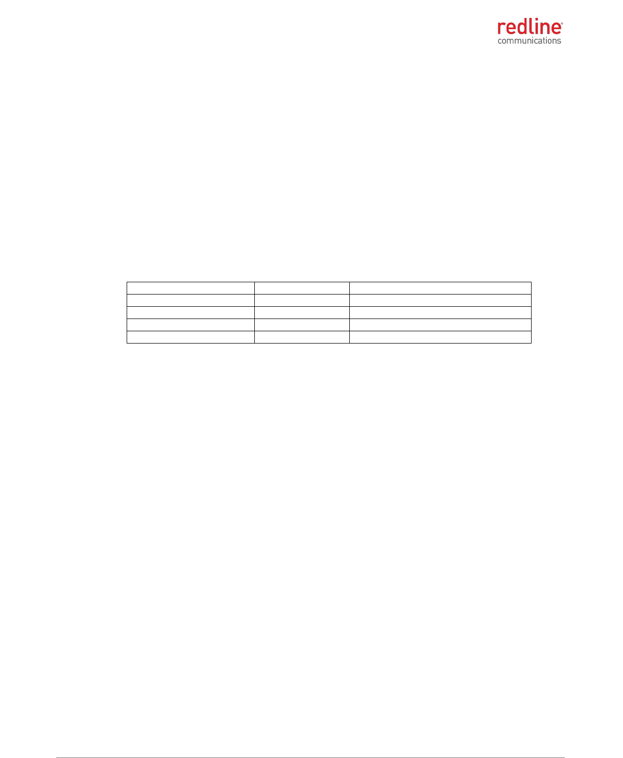
RDL-3000-RMC/E/F PRODUCT MANUAL
70-00184-03-02 Proprietary Redline Communications © 2013 Page 46 of 50 April 30, 2013
5.2 Industry Canada Notices: Deployment in Canada
5.2.1 RDL-3000-RMC
Deployment in Canada
This Class B Digital apparatus meets all the requirements of the Canadian Interference-
Causing Equipment.
The following notices about deployment in Canada are included in training and
documentation provided to professional installers and operators of the final product:
1. The final product must be professionally installed.
2. WARNING -- IC RF Exposure Warnings
To satisfy IC RF exposure requirements for RF transmitting devices, the following
distances should be maintained between the antenna of this device and persons
during device operation:
Table 79: IC: RDL-3000-RMC Recommended Safe Distances
Frequency (MHz)
Deployment
Separation Distance
4900
PMP
260 cm (103") or more
5300
PMP
20 cm (7.8") or more
5400
PMP
20 cm (7.8") or more
5800
PMP
20 cm (7.8") or more
To ensure compliance, operation at closer than these distances is not
recommended. The antenna used for this transmitter must not be collocated in
conjunction with any other antenna or transmitter.
The RDL-3000-RMC has been designed to operate with an antenna having a maximum
gain of 32 dBi. Antenna having a higher gain is strictly prohibited per regulations of
Industry Canada. The required antenna impedance is 50 ohms.
This device has been designed to ensure that radio frequency emissions are maintained
within the band of operation under all normal operating conditions listed in this manual.
This device complies with Industry Canada license-exempt RSS standard(s). Operation
is subject to the following two conditions:
1. This device may not cause interference, and
2. This device must accept any interference, including interference that may cause
undesired operation of the device.
To reduce potential radio interference to other users, the antenna type and its gain
should be so chosen that the equivalent isotropic radiated power (EIRP) is not more than
that required for successful communication.
Users should also be advised that high-power radars are allocated as primary users (i.e.
priority users) of the bands 5250-5350 MHz and 5650-5850 MHz and that these radars
could cause interference and/or damage to LE-LAN devices.
Déploiement aux le Canada
Cet appareil numérique de la classe B est conforme à la norme NMB-003 du Canada.
Les avis suivants à propos du déploiement au Canada sont inclus dans la formation et la
documentation fournies aux installateurs professionnels et les opérateurs du produit
final:
1. Le produit final doit être installé par un professionnel.
RDL-3000-RMC/E/F PRODUCT MANUAL
70-00184-03-02 Proprietary Redline Communications © 2013 Page 47 of 50 April 30, 2013
2. AVERTISSEMENT - IC avertissements d'exposition RF
Pour satisfaire les exigences d’IC en ce qui a trait aux expositions aux RF pour RF
dispositifs de transmission, les distances suivantes doit être maintenue entre
l'antenne de ce dispositif et des personnes pendant le fonctionnement du dispositif:
Table 80: IC: RDL-3000-RMC distances de sécurité recommandées
Frequency (MHz)
Deployment
Separation Distance
4900
PMP
260 cm (103") ou plus
5300
PMP
20 cm (7.8") ou plus
5400
PMP
20 cm (7.8") ou plus
5800
PMP
20 cm (7.8") ou plus
Le RDL-3000-RMC a été conçu pour fonctionner avec une antenne ayant un gain
maximal de 32 dBi. Antenne ayant un gain plus élevé est strictement interdite par les
règlements d'Industrie Canada. L'impédance d'antenne requise est de 50 ohms.
Ce dispositif a été conçu pour veiller à ce que les émissions de radiofréquences sont
maintenus dans la bande de fonctionnement dans toutes les conditions normales de
fonctionnement figurant dans ce manuel.
Cet appareil est conforme la norme d'Industrie Canada exempts de licence RSS (s). Son
fonctionnement est soumis aux deux conditions suivantes:
1. Cet appareil ne peut pas causer d'interférences, et
2. Cet appareil doit accepter toute interférence, y compris les interférences qui peuvent
causer un mauvais fonctionnement de l'appareil.
Pour réduire le potentiel d’interférence radio sur d’autres utilisateurs, le type d’antenne
et son gain doivent être choisies tel que la Puissance Isotrope Rayonnée Equivalente
(PIRE) ne dépasse pas le niveau nécessaire pour une communication efficace.
De plus, les utilisateurs devraient aussi être avisés que les utilisateurs de radars de
haute puissance sont désignés utilisateurs principaux (c.-à-d., qu’ils ont la priorité) pour
les bandes 5 250-5 350 MHz et 5 650-5 850 MHz et que ces radars pourraient causer
du brouillage et/ou des dommages aux dispositifs LAN-EL.
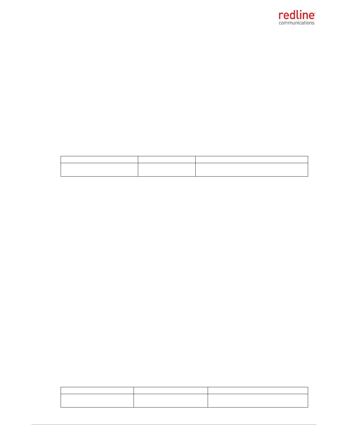
RDL-3000-RMC/E/F PRODUCT MANUAL
70-00184-03-02 Proprietary Redline Communications © 2013 Page 48 of 50 April 30, 2013
5.2.2 RDL-3000-RME
Deployment in Canada
This Class B Digital apparatus meets all the requirements of the Canadian Interference-
Causing Equipment.
Cet appareil numérique de la classe B est conforme à la norme NMB-003 du Canada.
The following notices about deployment in Canada are included in training and
documentation provided to professional installers and operators of the final product:
1. The final product must be professionally installed.
2. WARNING -- IC RF Exposure Warnings
To satisfy IC RF exposure requirements for RF transmitting devices, the following
distances should be maintained between the antenna of this device and persons
during device operation:
Table 81: IC: RDL-3000-RME/F Recommended Safe Distances
Frequency (MHz)
Deployment
Separation Distance
2305-2320
2345-2360
PMP
85 cm (33.5") or more
To ensure compliance, operation at closer than these distances is not
recommended. The antenna used for this transmitter must not be collocated in
conjunction with any other antenna or transmitter.
The RDL-3000-RME has been designed to operate with an antenna having a maximum
gain of 17 dBi. Antenna having a higher gain is strictly prohibited per regulations of
Industry Canada. The required antenna impedance is 50 ohms.
This device has been designed to ensure that radio frequency emissions are maintained
within the band of operation under all normal operating conditions listed in this manual.
IC regulations governing operation in the 2305-2320 MHz and 2345-2360 MHz bands
are subject to licensing, pursuant to subsection 4(1) of the Radiocommunication Act.
This equipment complies to RSS-195 in the frequency band 2305-2320 MHz and 2345-
2360 MHz bands.
Déploiement aux le Canada
Cet appareil Digitale de Classe B rencontre toutes les normes du Canadian Règlement
Brouilleur Équipement.
Les avis suivants à propos du déploiement au Canada sont inclus dans la formation et la
documentation fournies aux installateurs professionnels et les opérateurs du produit
final:
3. Le produit final doit être installé par un professionnel.
4. AVERTISSEMENT - IC avertissements d'exposition RF
Pour satisfaire les exigences d’IC en ce qui a trait aux expositions aux RF pour RF
dispositifs de transmission, les distances suivantes doit être maintenue entre
l'antenne de ce dispositif et des personnes pendant le fonctionnement du dispositif:
Table 82: IC: RDL-3000-RME/F distances de sécurité recommandées
Fréquence (MHz)
Déploiement
Distance de Séparation
2305-2320
2345-2360
PMP
85 cm (33.5") ou plus

RDL-3000-RMC/E/F PRODUCT MANUAL
70-00184-03-02 Proprietary Redline Communications © 2013 Page 49 of 50 April 30, 2013
Pour assurer la conformité , l’operation à une distance moindre que celles-ci n'est
pas recommandé. L'antenne utilisée pour ce transmetteur ne doit pas être co-
localisé avec une autre antenne ou transmetteur.
Le RDL-3000-RME a été conçu pour fonctionner avec une antenne ayant un gain
maximal de 17 dBi. Antenne ayant un gain plus élevé est strictement interdite par les
règlements d'Industrie Canada. L'impédance d'antenne requise est de 50 ohms.
Ce dispositif a été conçu pour veiller à ce que les émissions de radiofréquences sont
maintenus dans la bande de fonctionnement dans toutes les conditions normales de
fonctionnement figurant dans ce manuel.
Règlements qui régissent le fonctionnement IC dans la bandes 2305-2320 MHz et 2345-
2360 MHz sont soumises à autorisation en vertu du paragraphe 4 (1) de la Loi sur la
radiocommunication.
Cet équipement est conforme à RSS-195 dans la bandes de fréquences 2305-2320
MHz et 2345-2360 MHz.

RDL-3000 M2M Solutions
70-00184-03-02 Proprietary Redline Communications © 2013 Page 50 of 50 April 30, 2013
302 Town Centre Markham, Ontario Canada L3R 0E8
www.rdlcom.com