Redline Communications RDL3000RMG3 Advanced Broadband Wireless Infrastructure Solution User Manual 70 00184 10 01
Redline Communications Inc. Advanced Broadband Wireless Infrastructure Solution 70 00184 10 01
user manual

RDL-3000
70-00184-10-01 Proprietary Redline Communications © 2017 Page 1 of 26 October 5, 2017
RDL-3000 Family
Broadband Wireless Systems
RDL-3000-RMG3
Radio Modules
Product Manual
1 Product Overview ................................................................... 5
2 Conditions of Use ................................................................... 6
3 Module Installation and Service ............................................ 7
4 Final Product Requirements ................................................ 10
5 Regulatory Notices ............................................................... 23
RDL-3000 RMG3 MODULE PRODUCT MANUAL
70-00184-10-01 Proprietary Redline Communications © 2017 Page 2 of 26 September 21, 2017
Copyright Information
All rights reserved September 21, 2017. The information in this document is proprietary
to Redline Communications Inc. This document may not in whole or in part be copied,
reproduced, or reduced to any medium without prior consent in writing from Redline
Communications Incorporated.
Contact Information
Contact Information:
Redline Communications Inc.
302 Town Centre Blvd.
Markham, ON
Canada L3R 0E8
Web site: http://www.rdlcom.com
Email:
Inquiries: info@rdlcom.com
Support: support@rdlcom.com
Training: training@rdlcom.com
Document Control:
70-00184-10-01-RDL-3000-RMG3_Module_Product_Manual-20170921b.doc
Disclaimer
The statements, configurations, technical data, and recommendations in this document
are believed to be accurate and reliable, but are presented without express or implied
warranty. Additionally, Redline makes no representations or warranties, either expressed
or implied, regarding the contents of this product. Redline Communications shall not be
liable for any misuse regarding this product. The information in this document is subject
to change without notice. No part of this document shall be deemed to be part of any
warranty or contract unless specifically referenced to be part of such warranty or
contract within this document.

RDL-3000 RMG3 MODULE PRODUCT MANUAL
70-00184-10-01 Proprietary Redline Communications © 2017 Page 3 of 26 September 21, 2017
TABLE OF CONTENTS
1 Product Overview ................................................................... 5
2 Conditions of Use ................................................................... 6
2.1 General Conditions ............................................................................................ 6
2.2 Country of Use ................................................................................................... 6
2.3 Product Labeling ................................................................................................ 7
2.3.1 Module Label .................................................................................................... 7
2.3.2 External Label ................................................................................................... 7
3 Module Installation and Service ............................................ 7
3.1 Installation into a Final Product ........................................................................ 7
3.2 Module Servicing ............................................................................................... 8
3.3 Professional Installation .................................................................................... 9
3.4 Safety Precautions ............................................................................................. 9
3.5 Radio Frequency Safety .................................................................................... 9
4 Final Product Requirements ................................................ 10
4.1 Frequency Bands ............................................................................................. 10
4.1.1 Antenna Use and Transmit Power ................................................................... 10
4.1.2 Certified Antennas .......................................................................................... 10
4.1.3 Power & EIRP (MIMO Operation) .................................................................... 11
4.9 GHz: FCC 47 CFR Part 90 Subpart Y and RSS-111 ................................ 11
5.2 GHz: FCC 47 CFR Part 15 Subpart E, §15.407 ....................................... 14
5.8 GHz: FCC Part 15 Subpart Е and RSS-247 Issue 1 ............................... 17
5 Regulatory Notices ............................................................... 23
5.1.1 FCC Notices ................................................................................................... 23
5.1.2 Industry Canada Notices ................................................................................. 24

RDL-3000 RMG3 MODULE PRODUCT MANUAL
70-00184-10-01 Proprietary Redline Communications © 2017 Page 4 of 26 September 21, 2017
LIST OF TABLES
Table 1: Approved Antennas ......................................................................................... 10
Table 2: 4.9 GHz: RF Power & EIRP: 5 MHz channel & 10 dBi antenna ........................ 11
Table 3: 4.9 GHz: RF Power & EIRP: 5 MHz channel & 19 dBi antenna ........................ 11
Table 4: 4.9 GHz: RF Power & EIRP: 5 MHz channel & 24 dBi antenna ........................ 11
Table 5: 4.9 GHz: RF Power & EIRP: 5 MHz channel & 32 dBi antenna ........................ 11
Table 6: 4.9 GHz: RF Power & EIRP: 10 MHz channel & 10 dBi antenna ...................... 12
Table 7: 4.9 GHz: RF Power & EIRP: 10 MHz channel & 19 dBi antenna ...................... 12
Table 8: 4.9 GHz: RF Power & EIRP: 10 MHz channel & 24 dBi antenna ...................... 12
Table 9: 4.9 GHz: RF Power & EIRP: 10 MHz channel & 32 dBi antenna ...................... 12
Table 10: 4.9 GHz: RF Power & EIRP: 20 MHz channel & 10 dBi antenna .................... 13
Table 11: 4.9 GHz: RF Power & EIRP: 20 MHz channel & 19 dBi antenna .................... 13
Table 12: 4.9 GHz: RF Power & EIRP: 20 MHz channel & 24 dBi antenna .................... 13
Table 13: 4.9 GHz: RF Power & EIRP: 20 MHz channel & 32 dBi antenna .................... 13
Table 14: 5.2 GHz: RF Power & EIRP: 5 MHz channel 10 dBi antenna ......................... 14
Table 15: 5.2 GHz: RF Power & EIRP: 5 MHz channel 24 dBi antenna ......................... 14
Table 16: 5.2 GHz: RF Power & EIRP: 5 MHz channel 32 dBi antenna ......................... 14
Table 17: 5.2 GHz: RF Power & EIRP: 10 MHz channel 10 dBi antenna ....................... 15
Table 18: 5.2 GHz: RF Power & EIRP: 10 MHz channel 24 dBi antenna ....................... 15
Table 19: 5.2 GHz: RF Power & EIRP: 10 MHz channel 32 dBi antenna ....................... 15
Table 20: 5.2 GHz: RF Power & EIRP: 20 MHz channel 10 dBi antenna ....................... 16
Table 21: 5.2 GHz: RF Power & EIRP: 20 MHz channel 24 dBi antenna ....................... 16
Table 22: 5.2 GHz: RF Power & EIRP: 20 MHz channel 32 dBi antenna ....................... 16
Table 23: 5.8 GHz: RF Power & EIRP: 5 MHz channel, PMP 10 dBi antenna ............... 17
Table 24: 5.8 GHz: RF Power & EIRP: 5 MHz channel, PMP 24 dBi antenna ............... 17
Table 25: 5.8 GHz: RF Power & EIRP: 5 MHz channel, PMP 32 dBi antenna ............... 17
Table 26: 5.8 GHz: RF Power & EIRP: 10 MHz channel, PMP 10 dBi antenna ............. 18
Table 27: 5.8 GHz: RF Power & EIRP: 10 MHz channel, PMP 24 dBi antenna ............. 18
Table 28: 5.8 GHz: RF Power & EIRP: 10 MHz channel, PMP 32 dBi antenna ............. 18
Table 29: 5.8 GHz: RF Power & EIRP: 20 MHz channel, PMP 10 dBi antenna ............. 19
Table 30: 5.8 GHz: RF Power & EIRP: 20 MHz channel, PMP 24 dBi antenna ............. 19
Table 31: 5.8 GHz: RF Power & EIRP: 20 MHz channel, PMP 32 dBi antenna ............. 19
Table 32: 5.8 GHz: RF Power & EIRP: 5 MHz channel and PTP 10 dBi antenna .......... 20
Table 33: 5.8 GHz: RF Power & EIRP: 5 MHz channel and PTP 24 dBi antenna .......... 20
Table 34: 5.8 GHz: RF Power & EIRP: 5 MHz channel and PTP 32 dBi antenna .......... 20
Table 35: 5.8 GHz: RF Power & EIRP: 10 MHz channel PTP 10 dBi antenna ............... 21
Table 36: 5.8 GHz: RF Power & EIRP: 10 MHz channel PTP 24 dBi antenna ............... 21
Table 37: 5.8 GHz: RF Power & EIRP: 10 MHz channel and PTP 32 dBi antenna ........ 21
Table 38: 5.8 GHz: RF Power & EIRP: 20 MHz channel PTP 10 dBi antenna ............... 22
Table 39: 5.8 GHz: RF Power & EIRP: 20 MHz channel PTP 24 dBi antenna ............... 22
Table 40: 5.8 GHz: RF Power & EIRP: 20 MHz channel and PTP 32 dBi antenna ........ 22
Table 41: FCC: RDL-3000-RMG3 Recommended Safe Distances ................................ 23
Table 42: IC: RDL-3000-RMG3 Recommended Safe Distances .................................... 24
Table 43: IC: RDL-3000-RMG3 distances de sécurité recommandées .......................... 25

RDL-3000 RMG3 MODULE PRODUCT MANUAL
70-00184-10-01 Proprietary Redline Communications © 2017 Page 5 of 26 September 21, 2017
1 Product Overview
The RDL-3000-RMG3 radio module is comprised of a proprietary Media Access Control
(MAC) protocol engine and Time Division Duplexing (TDD)/ Orthogonal Frequency
Division Duplexing (OFDM) digital radio.
The module is not designed for stand-alone operation. The module is sold as one
component of a packaged system which includes a suitable housing for the module
connectors for required external components including a power supply and antenna
system. This is afterwards referred to as the 'final product'. The final product may be
designed and manufactured by Redline or a licensed third party.
Frequency settings within the specified frequency ranges are software keyed to be
compliant with specific regulatory agency requirements in the region of deployment.
USA & Canada: 4900 to 5975 MHz
Important: Read this entire document prior to installing or operating these modules.

RDL-3000 RMG3 MODULE PRODUCT MANUAL
70-00184-10-01 Proprietary Redline Communications © 2017 Page 6 of 26 September 21, 2017
2 Conditions of Use
2.1 General Conditions
The RDL-3000-RMG3 module is not provided for sale to the general public. The module
contains a proprietary radio interface and can not be directly connected to any standard
telecommunications or computer devices. This manual is provided as supplement to
technical and operational documentation and training provided by Redline and its
agents.
Any operation or use of this module in any manner not expressly specified within this
manual or approved in writing by Redline (or its agents) is expressly forbidden and voids
the users right to operate the module. This includes, but is not limited to, any
modification of the module hardware or software, installation of the module in a non
approved enclosure, and use with non approved antennas.
2.2 Country of Use
Refer to the regulatory notices in this document before installing or operating the
module.
Operation of the final product requires a software 'key' that is available exclusively from
Redline or its authorized agents. The software key is unique to each module and must
be installed and activated before the radio will operate. The key contains sufficient
security features that the professional installer and operator can not decode, modify,
substitute, or otherwise circumvent the operational restrictions imposed by the 'key'.
The software 'key' limits the transmit power, operating frequency range, and channel
bandwidth per the regulator domain governing the location where the radio will be
deployed. The operator does not have the option to select the country or regulatory
region of operation.
A radio can be configured in either master or client mode of operation. A radio in client
mode is always ‘passive listener’ and cannot initiate any transmission without receiving
and decoding a valid authorization message from a licensed master. A radio in master
mode (whether from start or after being switched from client mode) checks and controls
all functionality of a given radio as a master -including full DFS capabilities as required -
based on license key. The license key is issued to customers for every unit, based on
geographic location of the unit (eg. US), with all the required regulatory compliance
parameters enabled to ensure compliance
Operation in the United States
The RDL-3000-RMG3 module is certified with limited modular approval for use as an
'intentional radiator' in the United States as device FCC ID: QC8-RDL3000RMG3.
Operation in Canada
The RDL-3000-RMG3 module is certified with limited modular approval for use as an
'intentional radiator' in the Canada as IC: 4310A-RDL3000RMG3.
RDL-3000 RMG3 MODULE PRODUCT MANUAL
70-00184-10-01 Proprietary Redline Communications © 2017 Page 7 of 26 September 21, 2017
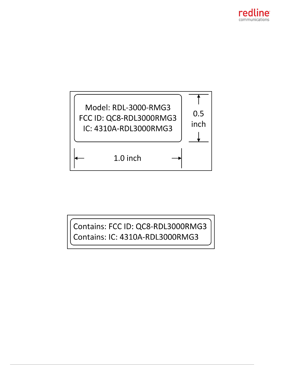
2.3 Product Labeling
2.3.1 Module Label
The modular transmitter will display a label referring to the FCC ID registration number
and the Industry Canada IC registration number. An information label is applied directly
to the modular transmitter (example shown below).
Do not to remove any labels from the module.
2.3.2 External Label
Information labels are applied to the final product. The final product features a label on
the outside surface listing the registration number for the enclosed module. Do not to
remove any labels from the module or the final product.
3 Module Installation and Service
3.1 Installation into a Final Product
The module must be installed only by trained professional technicians authorized by
Redline or its agents. The module must be installed only into an approved enclosure
(see Conditions of Use) and only at an approved manufacturing facility or service depot.
Redline shall retain complete control over the final installation of the module and will
ensure compliance of the end product to all applicable FCC/IC regulations. The module
must be installed only into an approved enclosure (see Conditions of Use) and only at an
approved manufacturing facility or service depot.
Redline licensing of the modular transmitter includes monitoring to ensure compliance in
the operation and use of the module as expressly specified within this manual. This
includes restrictions against modification of the module hardware, approval of the final
enclosure, operational restrictions for installers and end-users, and approval of antennas
provided for use with the product.
RDL-3000 RMG3 MODULE PRODUCT MANUAL
70-00184-10-01 Proprietary Redline Communications © 2017 Page 8 of 26 September 21, 2017
Operation of the final product requires the 'key' be controlled exclusively by the
manufacturer. The 'key' must be unique to each module and must be installed and
activated before the radio will operate. The key must contain sufficient security features
to the professional installer and operator can not decode, modify, substitute, or
otherwise circumvent the operational restrictions imposed by the 'key'.
The software 'key' must limit the transmit power, operating frequency range, and channel
bandwidth per the regulator domain governing the location where the radio will be
deployed. The operator does not have the option to select the country or regulatory
region of operation.
The software 'key' must limit the mode of operation as a master or client. The client
mode is 'passive listener' and while in this mode the module can not initiate any
transmission without first receiving and decoding a valid authorization message from the
master. A module with a key for client operation can not be changed by the installer to
enable master mode operation.
Redline will review all final products for compliance to regulatory restrictions.
The manufacturer must meet all labeling described in section 2.3.
3.2 Module Servicing
The module is not intended to be field serviceable, and contains no field serviceable or
field replaceable parts. The module must be serviced only at an approved manufacturing
facility or service depot.
Warning: The module is susceptible to damage from electrostatic charge.
Electrostatic Discharge (ESD) must be avoided to prevent damaging or destroying the
module. The module must always be store in an anti-static container/bag prior to
installation and following removal from the product for servicing. Observe ESD
precautions when handling the module.
RDL-3000 RMG3 MODULE PRODUCT MANUAL
70-00184-10-01 Proprietary Redline Communications © 2017 Page 9 of 26 September 21, 2017
3.3 Professional Installation
Devices containing the module require professional installation. It is the responsibility
of the installer to understand the product operation by attending training as required,
reading and understanding the product documentation, and ensuring that all building,
safety and regulatory codes are met and the installation is complete and secure.
3.4 Safety Precautions
Installation and service of the module must be performed by personnel having technical
training and experience necessary to be aware of hazards during installation and/or
service of RF equipment. The installation and/or service must be done using procedures
designed to minimize any danger to technical personnel or any other person.
3.5 Radio Frequency Safety
The installer of this radio equipment must ensure the antenna is located or pointed such
that it does not emit RF fields in excess of the general population limits as defined by:
FCC CFR 47, Part 2.1091
http://www.gpo.gov/fdsys/pkg/CFR-2009-title47-vol1/pdf/CFR-2009-title47-vol1-sec2-
1091.pdf
FCC OET Bulletin 65, Radio frequency radiation exposure evaluation for fixed
devices
http://transition.fcc.gov/Bureaus/Engineering_Technology/Documents/bulletins/oet65
/oet65c.pdf
Health Canada limits for the general population; consult Safety Code 6, obtainable
from Health Canada’s website:
http://www.hc-sc.gc.ca/ewh-semt/pubs/radiation/radio_guide-lignes_direct-eng.php
Refer to the regulatory statements included in this document.
RDL-3000 RMG3 MODULE PRODUCT MANUAL
70-00184-10-01 Proprietary Redline Communications © 2017 Page 10 of 26 September 21, 2017
4 Final Product Requirements
The following requirements apply to all final products incorporating an RDL-3000-RMG3,
module.
4.1 Frequency Bands
Operation of the final product requires a software 'key' that is available exclusively from
Redline. This key restricts device operation to the FCC/IC 4940-4990 MHz and 5725-
5850 MHz or FCC 5150-5250 MHz MHz band. The professional installer and operator
can not modify or otherwise circumvent these operational restrictions.
4.1.1 Antenna Use and Transmit Power
The module supports operation with 2x2 MIMO antenna systems with two transmit
chains and two receive chains. The module must be used only with certified antennas
and using the channel size and output power level specified by the FCC/IC regulations.
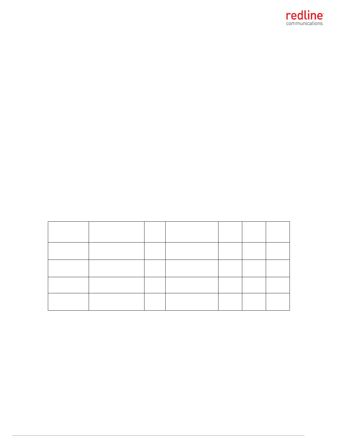
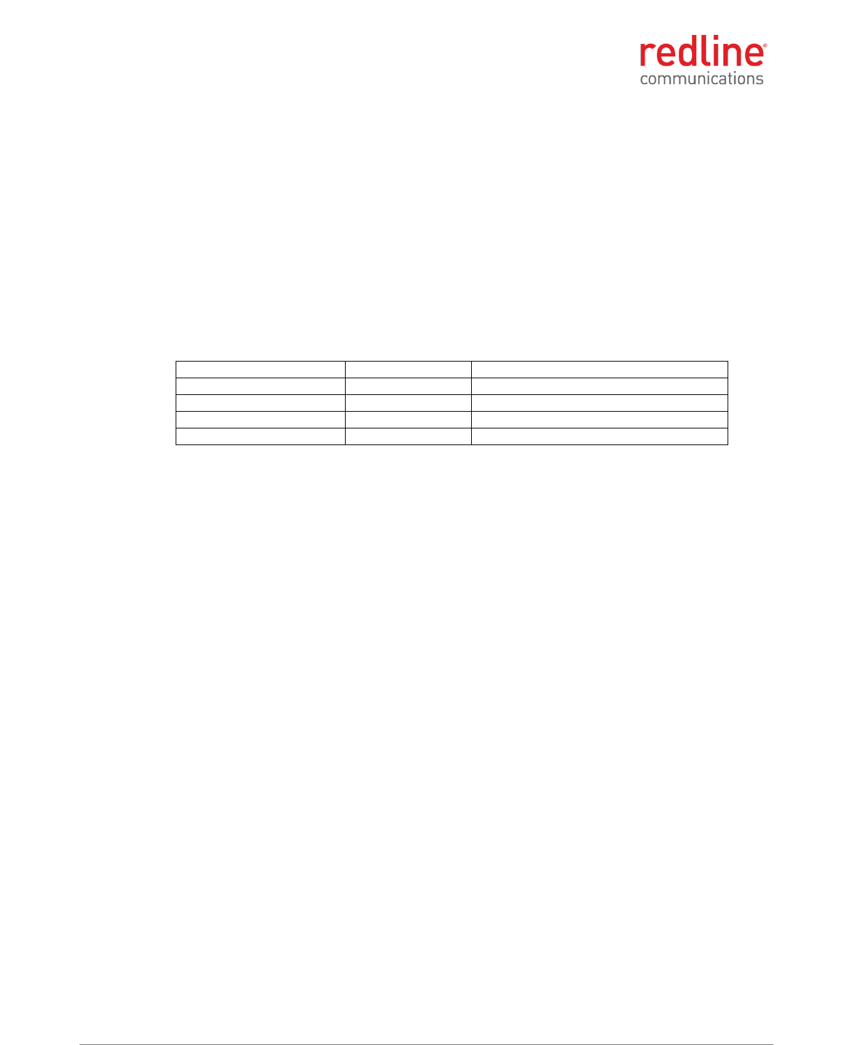
4.1.2 Certified Antennas
This device has been designed to operate with the antennas listed in the following table.
Any additional antennas will be used only after authorization is obtained through Class II
permissive change.
Table 1: Approved Antennas
Manufacturer
Part #
Gain
(dBi)
Frequency Range
4940-
4990
MHz
5150-
5250
MHz
5725-
5850
MHz
L-Com
Redline *
HG5158DP-10U
AOD-DB-0512-02
10
10
5100-5800 MHz
4940-5875 MHz
PMP
PMP
PMP
PMP
PMP
PMP
Redline
30-00328-50
19
4900-5875 MHz
PTP
PMP
PMP
PTP
PMP
Redline
30-00362-00
24
4900-6100 MHz
PTP
PMP
PMP
PMP
PTP
Redline
A3FT3204LTPD
32
4900-5875 MHz
PTP
PMP
PMP
PTP
PMP
* Alternate (equivalent) antenna.
RDL-3000 RMG3 MODULE PRODUCT MANUAL
70-00184-10-01 Proprietary Redline Communications © 2017 Page 11 of 26 September 21, 2017
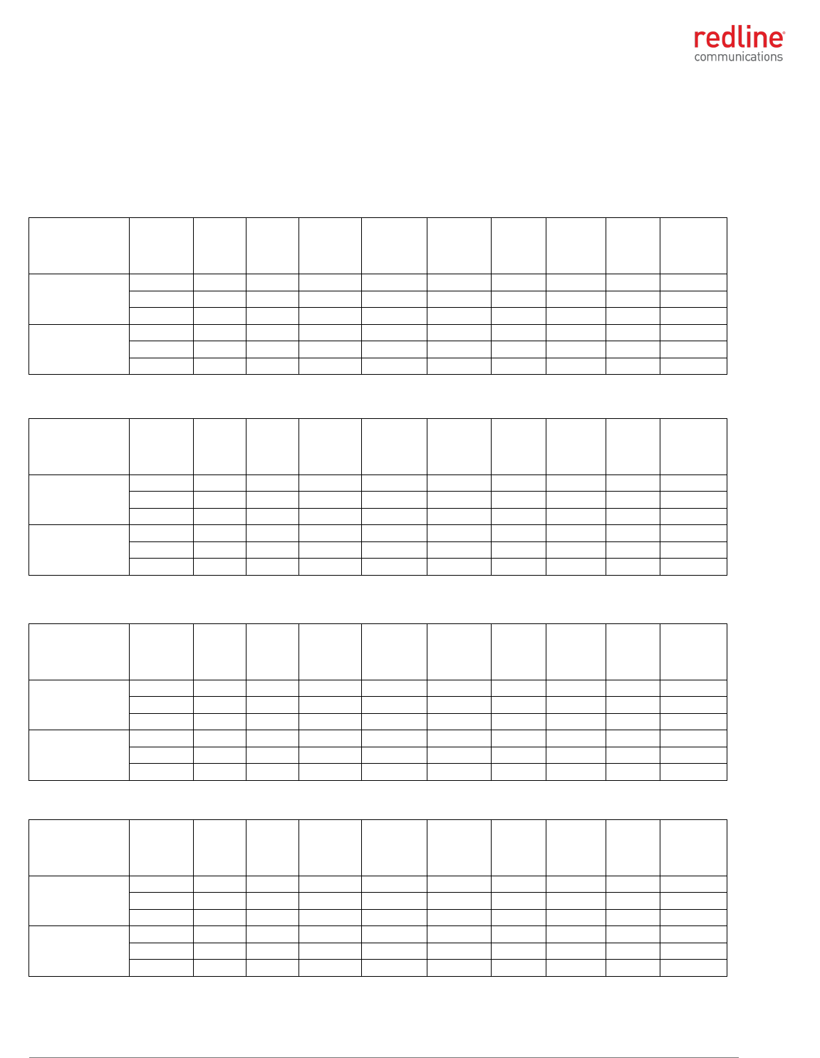
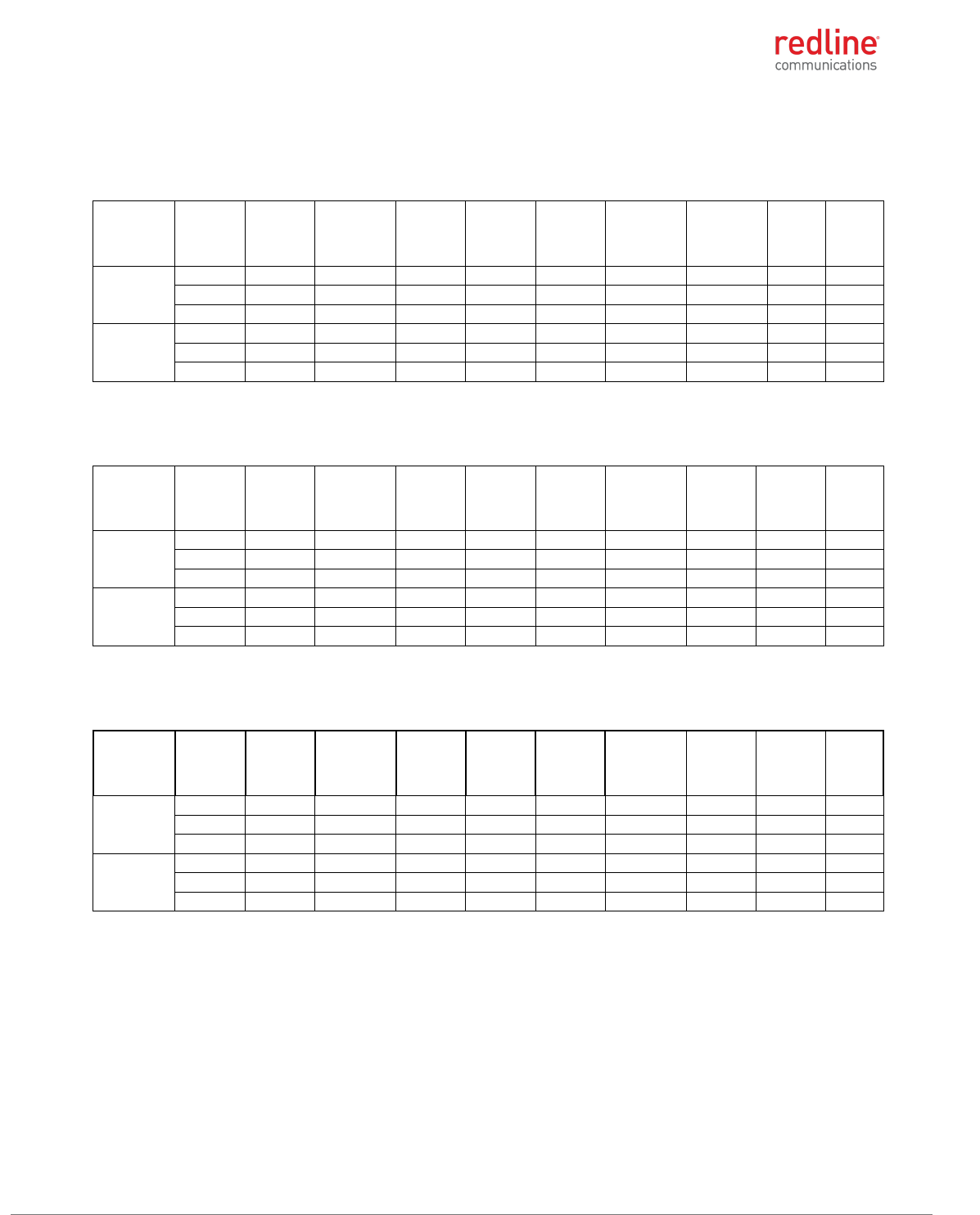
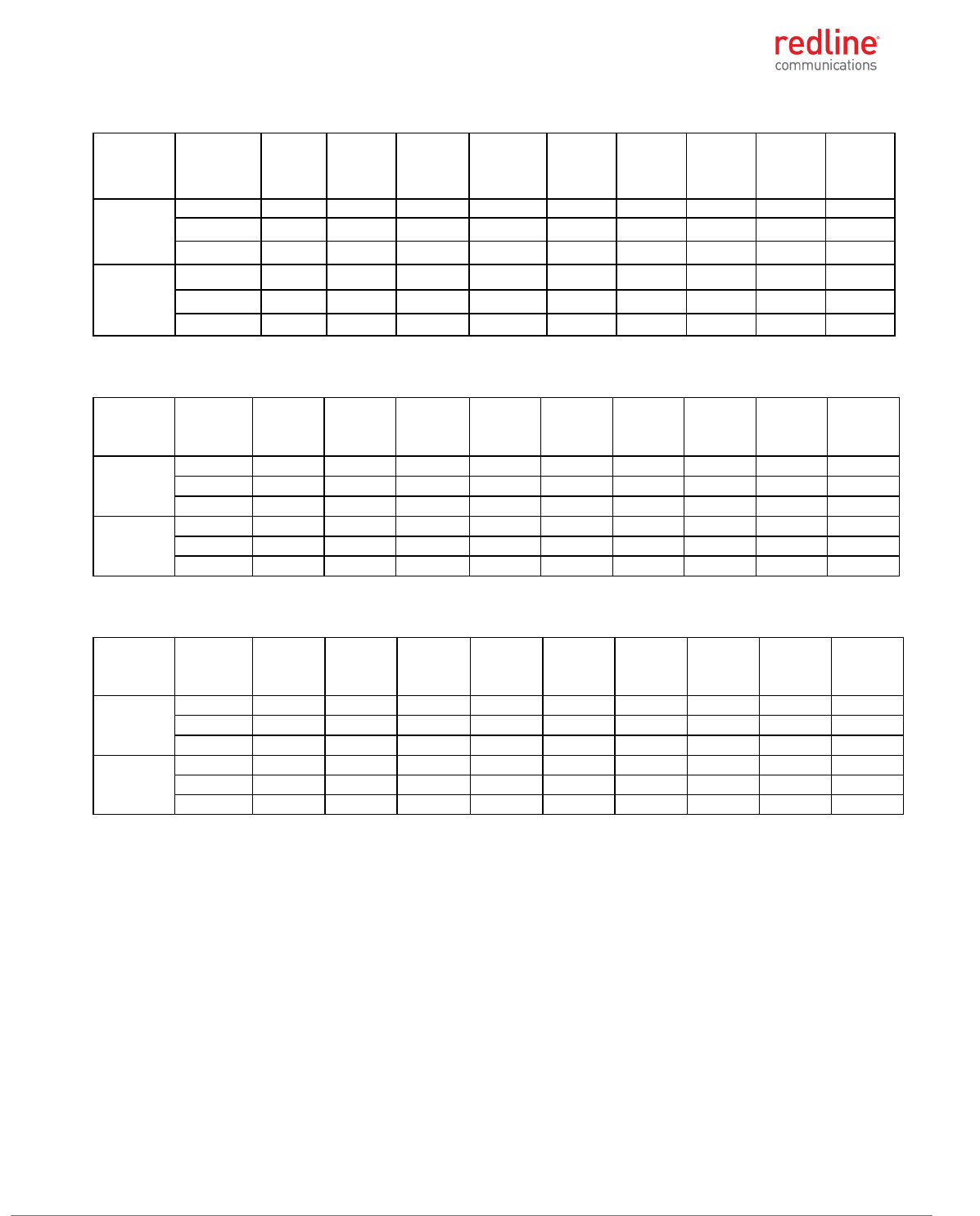
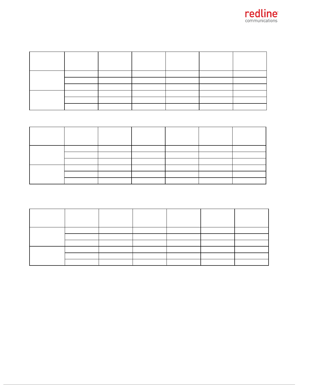
4.1.3 Power & EIRP (MIMO Operation)
4.9 GHz: FCC 47 CFR Part 90 Subpart Y and RSS-111
Table 2: 4.9 GHz: RF Power & EIRP: 5 MHz channel & 10 dBi antenna
Modulation
Frequency
(MHz)
Antena
1
power
(dBm)
Antena
2
power
(dBm)
Combined
power
(dBm)
Output
power
limit
(dBm)
Output
power
margin
(dB)
Antenna
gain
(dBi)
EIRP
(dBm)
EIRP
limit
(dBm)
EIRP
margin
(dB)
BPSK
4942.5
20.87
20.00
23.47
27.00
3.53
10.00
33.47
53.00
19.53
4965.0
20.52
20.36
23.45
27.00
3.55
10.00
33.45
53.00
19.55
4987.5
20.70
20.63
23.68
27.00
3.32
10.00
33.68
53.00
19.32
256-QAM
4942.5
20.82
20.12
23.49
27.00
3.51
10.00
33.49
53.00
19.51
4965.0
20.55
20.48
23.53
27.00
3.47
10.00
33.53
53.00
19.47
4987.5
20.71
20.64
23.69
27.00
3.31
10.00
33.69
53.00
19.31
Table 3: 4.9 GHz: RF Power & EIRP: 5 MHz channel & 19 dBi antenna
Modulation
Frequency
(MHz)
Antena
1
power
(dBm)
Antena
2
power
(dBm)
Combined
power
(dBm)
Output
power
limit
(dBm)
Output
power
margin
(dB)
Antenna
gain
(dBi)
EIRP
(dBm)
EIRP
limit
(dBm)
EIRP
margin
(dB)
BPSK
4942.5
20.87
20.00
23.47
27.00
3.53
19.00
42.47
53.00
10.53
4965.0
20.52
20.36
23.45
27.00
3.55
19.00
42.45
53.00
10.55
4987.5
20.70
20.63
23.68
27.00
3.32
19.00
42.68
53.00
10.32
256-QAM
4942.5
20.82
20.12
23.49
27.00
3.51
19.00
42.49
53.00
10.51
4965.0
20.55
20.48
23.53
27.00
3.47
19.00
42.53
53.00
10.47
4987.5
20.71
20.64
23.69
27.00
3.31
19.00
42.69
53.00
10.31
Table 4: 4.9 GHz: RF Power & EIRP: 5 MHz channel & 24 dBi antenna
Modulation
Frequency
(MHz)
Antena
1
power
(dBm)
Antena
2
power
(dBm)
Combined
power
(dBm)
Output
power
limit
(dBm)
Output
power
margin
(dB)
Antenna
gain
(dBi)
EIRP
(dBm)
EIRP
limit
(dBm)
EIRP
margin
(dB)
BPSK
4942.5
20.87
20.00
23.47
27.00
3.53
24.00
47.47
53.00
5.53
4965.0
20.52
20.36
23.45
27.00
3.55
24.00
47.45
53.00
5.55
4987.5
20.70
20.63
23.68
27.00
3.32
24.00
47.68
53.00
5.32
256-QAM
4942.5
20.82
20.12
23.49
27.00
3.51
24.00
47.49
53.00
5.51
4965.0
20.55
20.48
23.53
27.00
3.47
24.00
47.53
53.00
5.47
4987.5
20.71
20.64
23.69
27.00
3.31
24.00
47.69
53.00
5.31
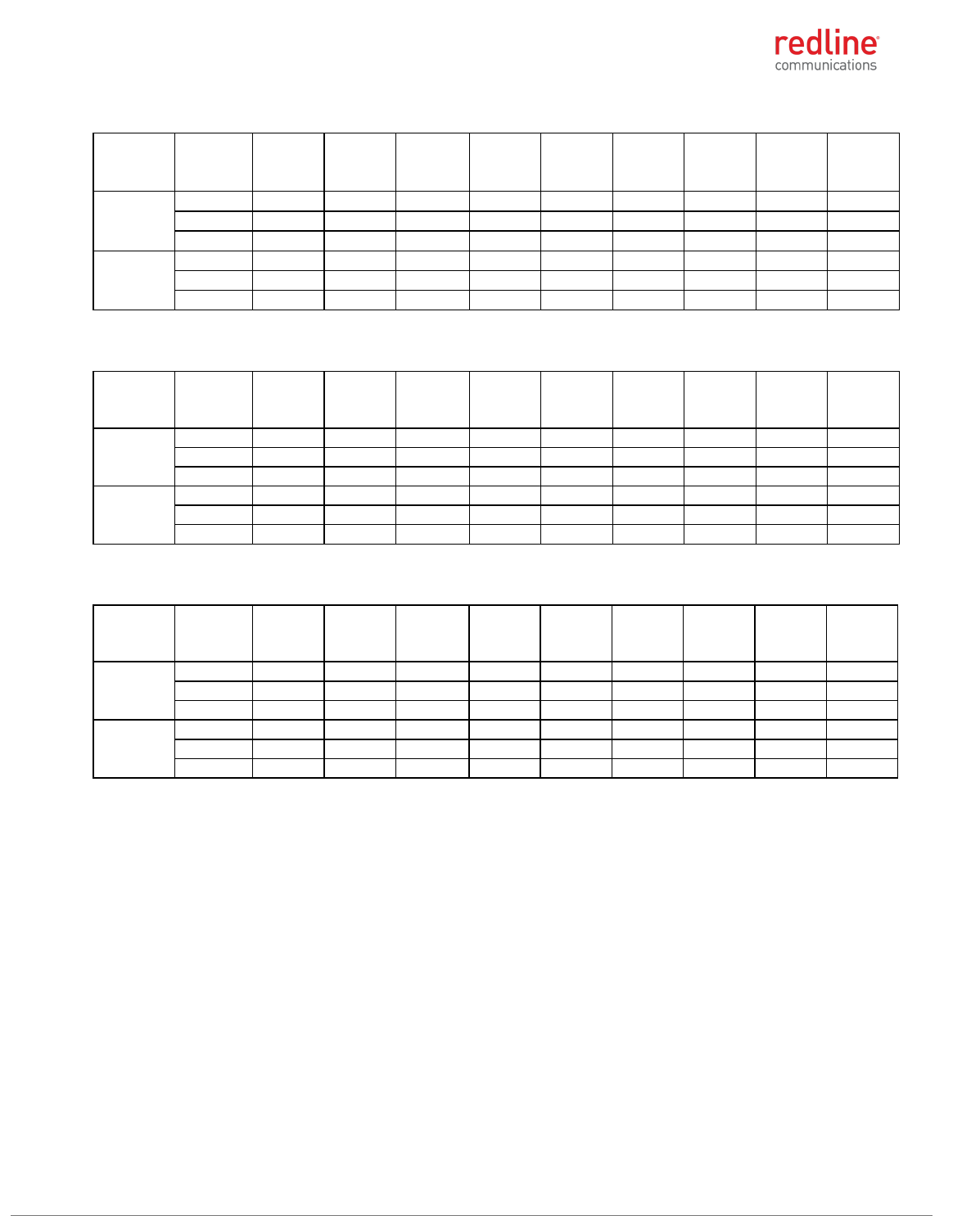
Table 5: 4.9 GHz: RF Power & EIRP: 5 MHz channel & 32 dBi antenna
Modulation
Frequency
(MHz)
Antena
1
power
(dBm)
Antena
2
power
(dBm)
Combined
power
(dBm)
Output
power
limit
(dBm)
Output
power
margin
(dB)
Antenna
gain
(dBi)
EIRP
(dBm)
EIRP
limit
(dBm)
EIRP
margin
(dB)
BPSK
4942.5
17.98
17.20
20.62
21.00
0.38
32.00
52.62
53.00
0.38
4965.0
17.52
17.62
20.58
21.00
0.42
32.00
52.58
53.00
0.42
4987.5
18.50
17.37
20.98
21.00
0.02
32.00
52.98
53.00
0.02
256-QAM
4942.5
18.00
17.30
20.67
21.00
0.33
32.00
52.67
53.00
0.33
4965.0
17.54
17.68
20.62
21.00
0.38
32.00
52.62
53.00
0.38
4987.5
18.52
17.33
20.98
21.00
0.02
32.00
52.98
53.00
0.02
RDL-3000 RMG3 MODULE PRODUCT MANUAL
70-00184-10-01 Proprietary Redline Communications © 2017 Page 12 of 26 September 21, 2017
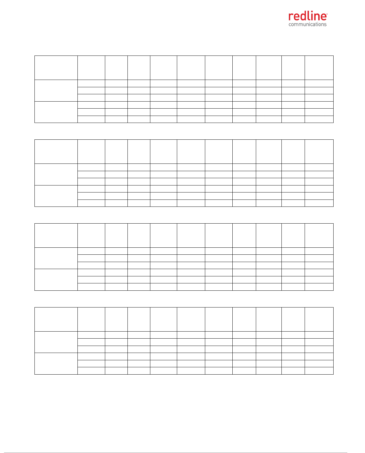
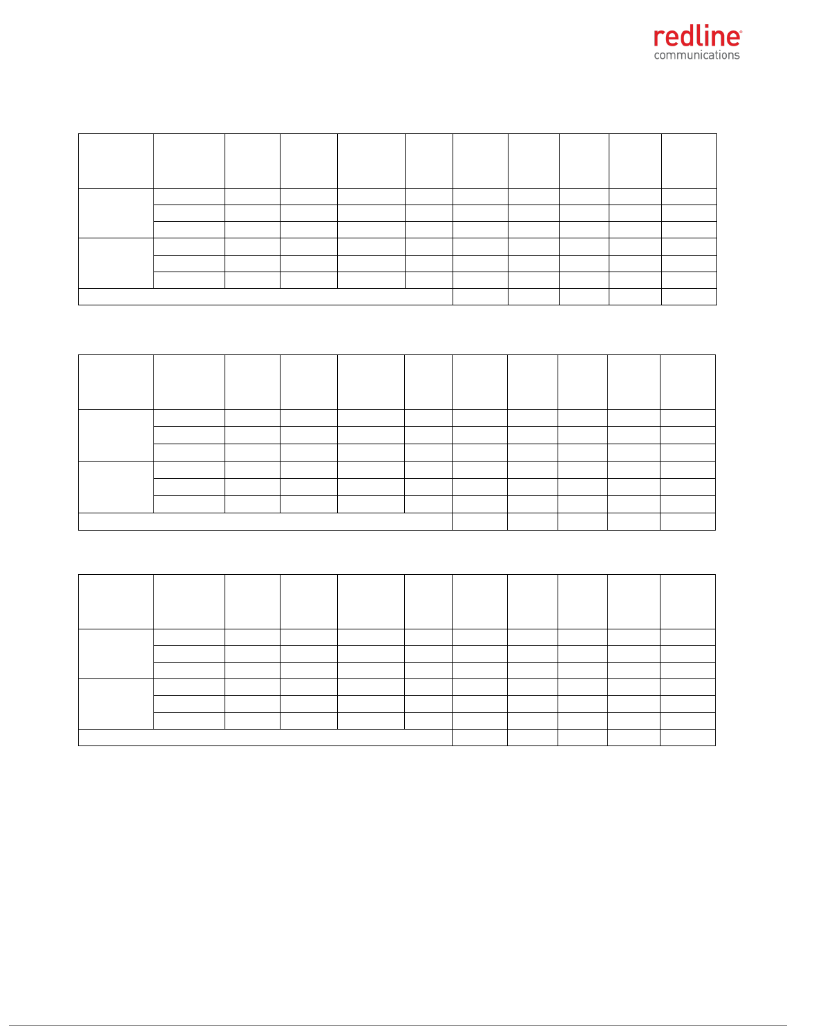
Table 6: 4.9 GHz: RF Power & EIRP: 10 MHz channel & 10 dBi antenna
Modulation
Frequency
(MHz)
Antena
1
power
(dBm)
Antena
2
power
(dBm)
Combined
power
(dBm)
Output
power
limit
(dBm)
Output
power
margin
(dB)
Antenna
gain
(dBi)
EIRP
(dBm)
EIRP
limit
(dBm)
EIRP
margin
(dB)
BPSK
4945.0
22.59
22.77
25.69
30.00
4.31
10.00
35.69
56.00
20.31
4965.0
22.22
22.20
25.22
30.00
4.78
10.00
35.22
56.00
20.78
4985.0
22.16
22.24
25.21
30.00
4.79
10.00
35.21
56.00
20.79
256-QAM
4945.0
22.62
22.64
25.64
30.00
4.36
10.00
35.64
56.00
20.36
4965.0
22.31
22.11
25.22
30.00
4.78
10.00
35.22
56.00
20.78
4985.0
22.18
22.25
25.23
30.00
4.77
10.00
35.23
56.00
20.77
Table 7: 4.9 GHz: RF Power & EIRP: 10 MHz channel & 19 dBi antenna
Modulation
Frequency
(MHz)
Antena
1
power
(dBm)
Antena
2
power
(dBm)
Combined
power
(dBm)
Output
power
limit
(dBm)
Output
power
margin
(dB)
Antenna
gain
(dBi)
EIRP
(dBm)
EIRP
limit
(dBm)
EIRP
margin
(dB)
BPSK
4945.0
22.59
22.77
25.69
30.00
4.31
19.00
44.69
56.00
11.31
4965.0
22.22
22.20
25.22
30.00
4.78
19.00
44.22
56.00
11.78
4985.0
22.16
22.24
25.21
30.00
4.79
19.00
44.21
56.00
11.79
256-QAM
4945.0
22.62
22.64
25.64
30.00
4.36
19.00
44.64
56.00
11.36
4965.0
22.31
22.11
25.22
30.00
4.78
19.00
44.22
56.00
11.78
4985.0
22.18
22.25
25.23
30.00
4.77
19.00
44.23
56.00
11.77
Table 8: 4.9 GHz: RF Power & EIRP: 10 MHz channel & 24 dBi antenna
Modulation
Frequency
(MHz)
Antena
1
power
(dBm)
Antena
2
power
(dBm)
Combined
power
(dBm)
Output
power
limit
(dBm)
Output
power
margin
(dB)
Antenna
gain
(dBi)
EIRP
(dBm)
EIRP
limit
(dBm)
EIRP
margin
(dB)
BPSK
4945.0
22.59
22.77
25.69
30.00
4.31
24.00
49.69
56.00
6.31
4965.0
22.22
22.20
25.22
30.00
4.78
24.00
49.22
56.00
6.78
4985.0
22.16
22.24
25.21
30.00
4.79
24.00
49.21
56.00
6.79
256-QAM
4945.0
22.62
22.64
25.64
30.00
4.36
24.00
49.64
56.00
6.36
4965.0
22.31
22.11
25.22
30.00
4.78
24.00
49.22
56.00
6.78
4985.0
22.18
22.25
25.23
30.00
4.77
24.00
49.23
56.00
6.77
Table 9: 4.9 GHz: RF Power & EIRP: 10 MHz channel & 32 dBi antenna
Modulation
Frequency
(MHz)
Antena
1
power
(dBm)
Antena
2
power
(dBm)
Combined
power
(dBm)
Output
power
limit
(dBm)
Output
power
margin
(dB)
Antenna
gain
(dBi)
EIRP
(dBm)
EIRP
limit
(dBm)
EIRP
margin
(dB)
BPSK
4945.0
20.63
19.85
23.27
24.00
0.73
32.00
55.27
56.00
0.73
4965.0
20.44
20.48
23.47
24.00
0.53
32.00
55.47
56.00
0.53
4985.0
20.46
20.77
23.63
24.00
0.37
32.00
55.63
56.00
0.37
256-QAM
4945.0
20.59
19.85
23.25
24.00
0.75
32.00
55.25
56.00
0.75
4965.0
20.51
20.51
23.52
24.00
0.48
32.00
55.52
56.00
0.48
4985.0
20.38
20.71
23.56
24.00
0.44
32.00
55.56
56.00
0.44
RDL-3000 RMG3 MODULE PRODUCT MANUAL
70-00184-10-01 Proprietary Redline Communications © 2017 Page 13 of 26 September 21, 2017
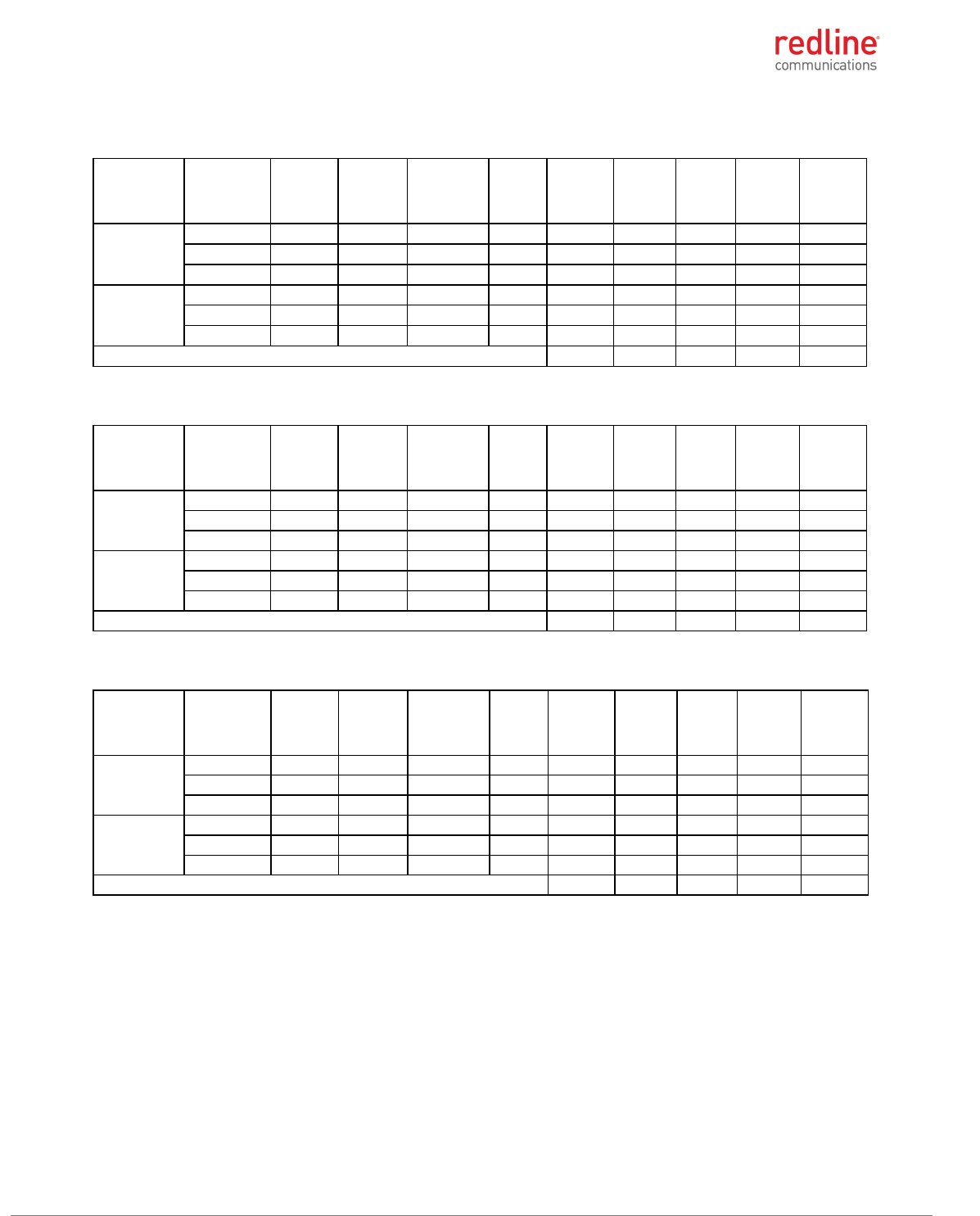
Table 10: 4.9 GHz: RF Power & EIRP: 20 MHz channel & 10 dBi antenna
Modulation
Frequency
(MHz)
Antena
1
power
(dBm)
Antena
2
power
(dBm)
Combined
power
(dBm)
Output
power
limit
(dBm)
Output
power
margin
(dB)
Antenna
gain
(dBi)
EIRP
(dBm)
EIRP
limit
(dBm)
EIRP
margin
(dB)
BPSK
4950.0
22.78
23.07
25.94
33.00
7.06
10.00
35.94
59.00
23.06
4965.0
22.44
22.67
25.57
33.00
7.43
10.00
35.57
59.00
23.43
4980.0
22.53
22.59
25.57
33.00
7.43
10.00
35.57
59.00
23.43
256-QAM
4950.0
22.73
22.99
25.87
33.00
7.13
10.00
35.87
59.00
23.13
4965.0
22.42
22.66
25.55
33.00
7.45
10.00
35.55
59.00
23.45
4980.0
22.61
22.57
25.60
33.00
7.40
10.00
35.60
59.00
23.40
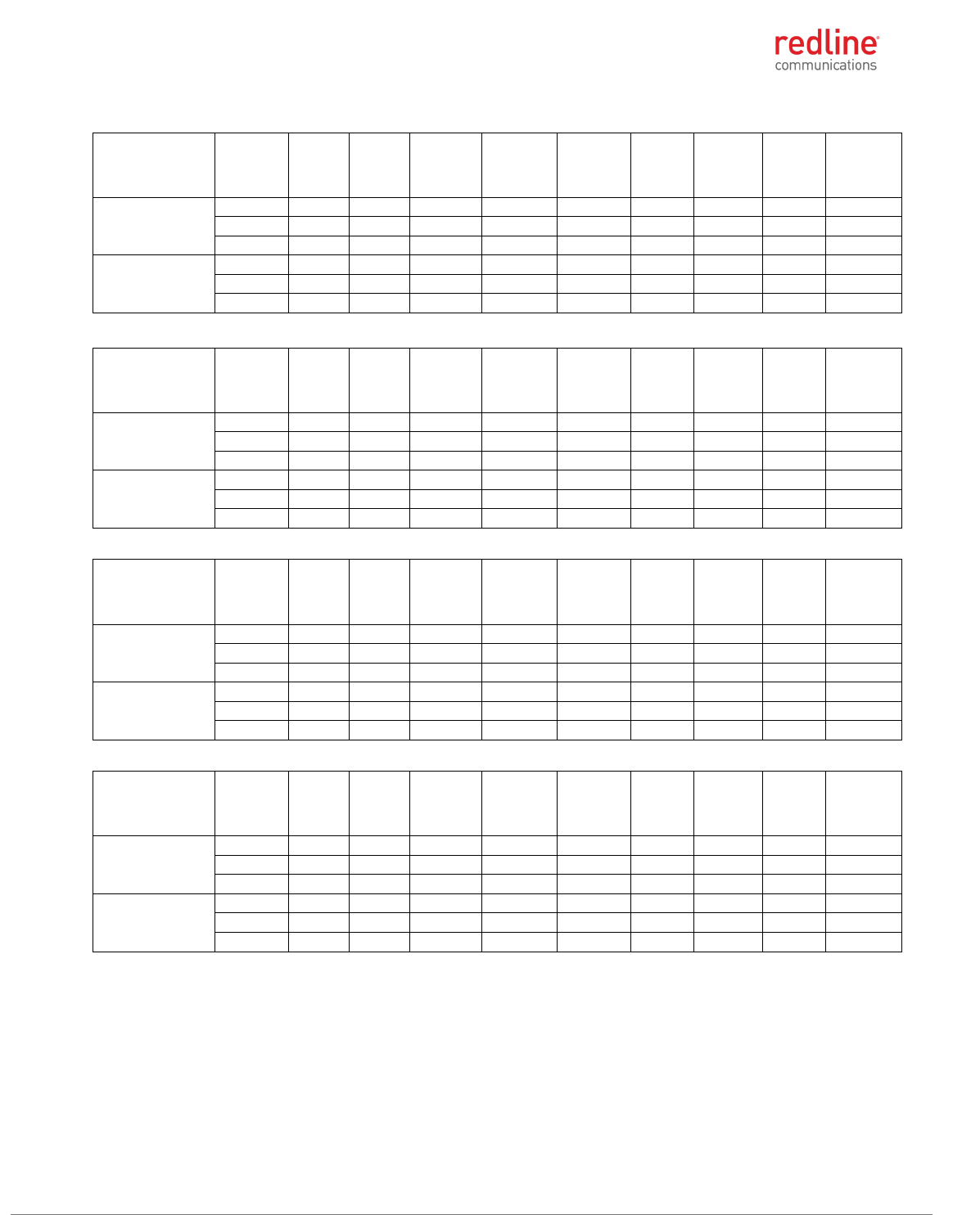
Table 11: 4.9 GHz: RF Power & EIRP: 20 MHz channel & 19 dBi antenna
Modulation
Frequency
(MHz)
Antena
1
power
(dBm)
Antena
2
power
(dBm)
Combined
power
(dBm)
Output
power
limit
(dBm)
Output
power
margin
(dB)
Antenna
gain
(dBi)
EIRP
(dBm)
EIRP
limit
(dBm)
EIRP
margin
(dB)
BPSK
4950.0
22.78
23.07
25.94
33.00
7.06
19.00
44.94
59.00
14.06
4965.0
22.44
22.67
25.57
33.00
7.43
19.00
44.57
59.00
14.43
4980.0
22.53
22.59
25.57
33.00
7.43
19.00
44.57
59.00
14.43
256-QAM
4950.0
22.73
22.99
25.87
33.00
7.13
19.00
44.87
59.00
14.13
4965.0
22.42
22.66
25.55
33.00
7.45
19.00
44.55
59.00
14.45
4980.0
22.61
22.57
25.60
33.00
7.40
19.00
44.60
59.00
14.40
Table 12: 4.9 GHz: RF Power & EIRP: 20 MHz channel & 24 dBi antenna
Modulation
Frequency
(MHz)
Antena
1
power
(dBm)
Antena
2
power
(dBm)
Combined
power
(dBm)
Output
power
limit
(dBm)
Output
power
margin
(dB)
Antenna
gain
(dBi)
EIRP
(dBm)
EIRP
limit
(dBm)
EIRP
margin
(dB)
BPSK
4950.0
22.78
23.07
25.94
33.00
7.06
24.00
49.94
59.00
9.06
4965.0
22.44
22.67
25.57
33.00
7.43
24.00
49.57
59.00
9.43
4980.0
22.53
22.59
25.57
33.00
7.43
24.00
49.57
59.00
9.43
256-QAM
4950.0
22.73
22.99
25.87
33.00
7.13
24.00
49.87
59.00
9.13
4965.0
22.42
22.66
25.55
33.00
7.45
24.00
49.55
59.00
9.45
4980.0
22.61
22.57
25.60
33.00
7.40
24.00
49.60
59.00
9.40
Table 13: 4.9 GHz: RF Power & EIRP: 20 MHz channel & 32 dBi antenna
Modulation
Frequency
(MHz)
Antena
1
power
(dBm)
Antena
2
power
(dBm)
Combined
power
(dBm)
Output
power
limit
(dBm)
Output
power
margin
(dB)
Antenna
gain
(dBi)
EIRP
(dBm)
EIRP
limit
(dBm)
EIRP
margin
(dB)
BPSK
4950.0
22.78
23.07
25.94
27.00
1.06
32.00
57.94
59.00
1.06
4965.0
22.44
22.67
25.57
27.00
1.43
32.00
57.57
59.00
1.43
4980.0
22.53
22.59
25.57
27.00
1.43
32.00
57.57
59.00
1.43
256-QAM
4950.0
22.73
22.99
25.87
27.00
1.13
32.00
57.87
59.00
1.13
4965.0
22.42
22.66
25.55
27.00
1.45
32.00
57.55
59.00
1.45
4980.0
22.61
22.57
25.60
27.00
1.40
32.00
57.60
59.00
1.40
RDL-3000 RMG3 MODULE PRODUCT MANUAL
70-00184-10-01 Proprietary Redline Communications © 2017 Page 14 of 26 September 21, 2017
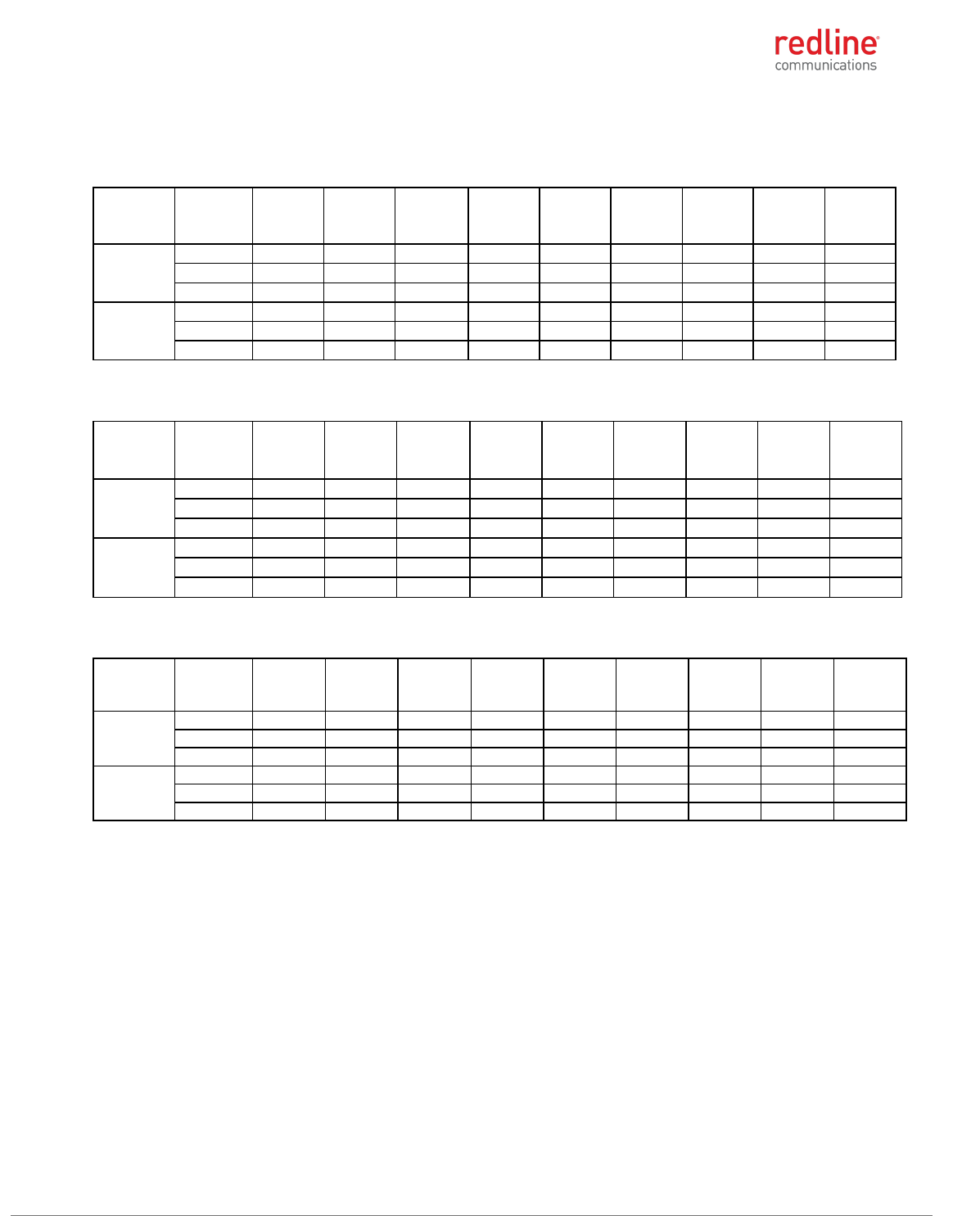
5.2 GHz: FCC 47 CFR Part 15 Subpart E, §15.407
Table 14: 5.2 GHz: RF Power & EIRP: 5 MHz channel 10 dBi antenna
Modulation
Frequenc
y, MHz
Output
power
on ch0,
dBm
Output
power on
ch0, dBm
Combine
d power,
dBm
Limit,
dBm
Margin,
dB
Tot. Gain,
dBi
EIRP, dBm
Limit,
dBm
Margin
, dB
BPSK
5155.0
9.81
9.96
12.90
26.70
13.80
9.30
22.20
36.00
13.80
5200.0
16.11
16.22
19.18
26.70
7.52
9.30
28.48
36.00
7.52
5247.5
15.82
15.77
18.81
26.70
7.89
9.30
28.11
36.00
7.89
256-QAM
5155.0
9.79
9.82
12.82
26.70
13.88
9.30
22.12
36.00
13.88
5200.0
16.01
16.15
19.09
26.70
7.61
9.30
28.39
36.00
7.61
5247.5
15.82
15.73
18.79
26.70
7.91
9.30
28.09
36.00
7.91
Note: Total antenna gain includes 0.7 dB loss of the cable
Table 15: 5.2 GHz: RF Power & EIRP: 5 MHz channel 24 dBi antenna
Modulation
Frequenc
y, MHz
Output
power
on ch0,
dBm
Output
power on
ch0, dBm
Combine
d power,
dBm
Limit,
dBm
Margin,
dB
Tot. Gain,
dBi
EIRP,
dBm
Limit,
dBm
Margin
, dB
BPSK
5155.0
0.41
0.61
3.52
12.70
9.18
23.30
26.82
36.00
9.18
5200.0
0.51
0.43
3.48
12.70
9.22
23.30
26.78
36.00
9.22
5247.5
0.36
0.44
3.41
12.70
9.29
23.30
26.71
36.00
9.29
256-QAM
5155.0
0.46
0.59
3.54
12.70
9.16
23.30
26.84
36.00
9.16
5200.0
0.59
0.39
3.50
12.70
9.20
23.30
26.80
36.00
9.20
5247.5
0.41
0.42
3.43
12.70
9.27
23.30
26.73
36.00
9.27
Note: Total antenna gain includes 0.7 dB loss of the cable
Table 16: 5.2 GHz: RF Power & EIRP: 5 MHz channel 32 dBi antenna
Modulation
Frequenc
y, MHz
Output
power
on ch0,
dBm
Output
power on
ch0, dBm
Combine
d power,
dBm
Limit,
dBm
Margin,
dB
Tot. Gain,
dBi
EIRP,
dBm
Limit,
dBm
Margin
, dB
BPSK
5155.0
-7.12
-7.22
-4.16
4.70
8.86
31.30
27.14
36.00
8.86
5200.0
-7.31
-7.55
-4.42
4.70
9.12
31.30
26.88
36.00
9.12
5247.5
-7.43
-7.62
-4.51
4.70
9.21
31.30
26.79
36.00
9.21
256-QAM
5155.0
-7.23
-7.51
-4.36
4.70
9.06
31.30
26.94
36.00
9.06
5200.0
-7.35
-7.65
-4.49
4.70
9.19
31.30
26.81
36.00
9.19
5247.5
-7.42
-7.66
-4.53
4.70
9.23
31.30
26.77
36.00
9.23
Note: Total antenna gain includes 0.7 dB loss of the cable
RDL-3000 RMG3 MODULE PRODUCT MANUAL
70-00184-10-01 Proprietary Redline Communications © 2017 Page 15 of 26 September 21, 2017
Table 17: 5.2 GHz: RF Power & EIRP: 10 MHz channel 10 dBi antenna
Modulation
Frequency,
MHz
Output
power
on ch0,
dBm
Output
power
on ch0,
dBm
Combined
power,
dBm
Limit,
dBm
Margin,
dB
Tot.
Gain,
dBi
EIRP,
dBm
Limit,
dBm
Margin,
dB
BPSK
5160
16.87
16.92
19.91
26.70
6.79
9.30
29.21
36.00
6.79
5200
16.89
16.87
19.89
26.70
6.81
9.30
29.19
36.00
6.81
5245
16.59
16.62
19.62
26.70
7.08
9.30
28.92
36.00
7.08
256-QAM
5160
16.84
16.89
19.88
26.70
6.82
9.30
29.18
36.00
6.82
5200
16.88
16.75
19.83
26.70
6.87
9.30
29.13
36.00
6.87
5245
16.61
16.71
19.67
26.70
7.03
9.30
28.97
36.00
7.03
Note: Total antenna gain includes 0.7 dB loss of the cable
Table 18: 5.2 GHz: RF Power & EIRP: 10 MHz channel 24 dBi antenna
Modulation
Frequency,
MHz
Output
power
on ch0,
dBm
Output
power
on ch0,
dBm
Combined
power,
dBm
Limit,
dBm
Margin,
dB
Tot.
Gain,
dBi
EIRP,
dBm
Limit,
dBm
Margin,
dB
BPSK
5160
3.35
3.33
6.35
12.70
6.35
23.30
29.65
36.00
6.35
5200
3.51
3.51
6.52
12.70
6.18
23.30
29.82
36.00
6.18
5245
3.22
3.40
6.32
12.70
6.38
23.30
29.62
36.00
6.38
256-QAM
5160
3.61
3.55
6.59
12.70
6.11
23.30
29.89
36.00
6.11
5200
3.58
3.61
6.61
12.70
6.09
23.30
29.91
36.00
6.09
5245
3.18
3.22
6.21
12.70
6.49
23.30
29.51
36.00
6.49
Note: Total antenna gain includes 0.7 dB loss of the cable
Table 19: 5.2 GHz: RF Power & EIRP: 10 MHz channel 32 dBi antenna
Modulation
Frequency,
MHz
Output
power
on ch0,
dBm
Output
power
on ch0,
dBm
Combined
power,
dBm
Limit,
dBm
Margin,
dB
Tot.
Gain,
dBi
EIRP,
dBm
Limit,
dBm
Margin,
dB
BPSK
5160
-4.64
-4.58
-1.60
4.70
6.30
31.30
29.70
36.00
6.30
5200
-4.72
-4.69
-1.69
4.70
6.39
31.30
29.61
36.00
6.39
5245
-4.81
-4.77
-1.78
4.70
6.48
31.30
29.52
36.00
6.48
256-QAM
5160
-4.42
-4.45
-1.42
4.70
6.12
31.30
29.88
36.00
6.12
5200
-4.62
-4.56
-1.58
4.70
6.28
31.30
29.72
36.00
6.28
5245
-4.73
-4.55
-1.63
4.70
6.33
31.30
29.67
36.00
6.33
Note: Total antenna gain includes 0.7 dB loss of the cable
RDL-3000 RMG3 MODULE PRODUCT MANUAL
70-00184-10-01 Proprietary Redline Communications © 2017 Page 16 of 26 September 21, 2017
Table 20: 5.2 GHz: RF Power & EIRP: 20 MHz channel 10 dBi antenna
Modulation
Frequency,
MHz
Output
power
on ch0,
dBm
Output
power
on ch0,
dBm
Combined
power,
dBm
Limit,
dBm
Margin,
dB
Tot.
Gain,
dBi
EIRP,
dBm
Limit,
dBm
Margin,
dB
BPSK
5170
18.22
18.17
21.21
26.70
5.49
9.30
30.51
36.00
5.49
5200
20.14
20.18
23.17
26.70
3.53
9.30
32.47
36.00
3.53
5240
19.81
19.97
22.90
26.70
3.80
9.30
32.20
36.00
3.80
256-QAM
5170
18.25
18.23
21.25
26.70
5.45
9.30
30.55
36.00
5.45
5200
20.25
20.33
23.30
26.70
3.40
9.30
32.60
36.00
3.40
5240
19.83
19.90
22.88
26.70
3.82
9.30
32.18
36.00
3.82
Note: Total antenna gain includes 0.7 dB loss of the cable
Table 21: 5.2 GHz: RF Power & EIRP: 20 MHz channel 24 dBi antenna
Modulation
Frequency,
MHz
Output
power
on ch0,
dBm
Output
power
on ch0,
dBm
Combined
power,
dBm
Limit,
dBm
Margin,
dB
Tot.
Gain,
dBi
EIRP,
dBm
Limit,
dBm
Margin,
dB
BPSK
5170
5.59
5.89
8.75
12.70
3.95
23.30
32.05
36.00
3.95
5200
5.61
5.67
8.65
12.70
4.05
23.30
31.95
36.00
4.05
5240
5.32
5.44
8.39
12.70
4.31
23.30
31.69
36.00
4.31
256-QAM
5170
5.55
5.87
8.72
12.70
3.98
23.30
32.02
36.00
3.98
5200
5.63
5.62
8.64
12.70
4.06
23.30
31.94
36.00
4.06
5240
5.35
5.46
8.42
12.70
4.28
23.30
31.72
36.00
4.28
Note: Total antenna gain includes 0.7 dB loss of the cable
Table 22: 5.2 GHz: RF Power & EIRP: 20 MHz channel 32 dBi antenna
Modulation
Frequency,
MHz
Output
power
on ch0,
dBm
Output
power
on ch0,
dBm
Combined
power,
dBm
Limit,
dBm
Margin,
dB
Tot.
Gain,
dBi
EIRP,
dBm
Limit,
dBm
Margin,
dB
BPSK
5170
-2.42
-2.15
0.73
4.70
3.97
31.30
32.03
36.00
3.97
5200
-2.59
-2.33
0.55
4.70
4.15
31.30
31.85
36.00
4.15
5240
-2.91
-2.60
0.26
4.70
4.44
31.30
31.56
36.00
4.44
256-QAM
5170
-2.51
-2.21
0.65
4.70
4.05
31.30
31.95
36.00
4.05
5200
-2.55
-2.36
0.56
4.70
4.14
31.30
31.86
36.00
4.14
5240
-2.89
-2.58
0.28
4.70
4.42
31.30
31.58
36.00
4.42
Note: Total antenna gain includes 0.7 dB loss of the cable
RDL-3000 RMG3 MODULE PRODUCT MANUAL
70-00184-10-01 Proprietary Redline Communications © 2017 Page 17 of 26 September 21, 2017
5.8 GHz: FCC Part 15 Subpart Е and RSS-247 Issue 1
Table 23: 5.8 GHz: RF Power & EIRP: 5 MHz channel, PMP 10 dBi antenna
Modulation
Frequency,
MHz
Output
power on
ch0, dBm
Output
power on
ch0, dBm
Combined
power,
dBm
Limit,
dBm
Margin,
dB
Tot. Gain,
dBi
EIRP,
dBm
Limit,
dBm
Margin,
dB
BPSK
5727.50
23.12
23.32
26.23
26.70
0.47
9.30
35.53
36.00
0.47
5790.00
22.10
22.35
25.24
26.70
1.46
9.30
34.54
36.00
1.46
5847.50
22.70
22.81
25.77
26.70
0.93
9.30
35.07
36.00
0.93
256-QAM
5727.50
23.30
23.55
26.44
26.70
0.26
9.30
35.74
36.00
0.26
5790.00
22.11
22.60
25.37
26.70
1.33
9.30
34.67
36.00
1.33
5847.50
22.71
22.99
25.86
26.70
0.84
9.30
35.16
36.00
0.84
Note: Total antenna gain includes 0.7 dB loss of the cable
Table 24: 5.8 GHz: RF Power & EIRP: 5 MHz channel, PMP 24 dBi antenna
Modulation
Frequency,
MHz
Output
power on
ch0, dBm
Output
power on
ch0, dBm
Combined
power,
dBm
Limit,
dBm
Margin,
dB
Tot. Gain,
dBi
EIRP,
dBm
Limit,
dBm
Margin,
dB
BPSK
5727.50
9.04
9.22
12.14
12.70
0.56
23.30
35.44
36.00
0.56
5790.00
8.07
8.33
11.21
12.70
1.49
23.30
34.51
36.00
1.49
5847.50
8.78
8.92
11.86
12.70
0.84
23.30
35.16
36.00
0.84
256-QAM
5727.50
9.08
9.23
12.17
12.70
0.53
23.30
35.47
36.00
0.53
5790.00
8.08
8.22
11.16
12.70
1.54
23.30
34.46
36.00
1.54
5847.50
8.82
8.98
11.91
12.70
0.79
23.30
35.21
36.00
0.79
Note: Total antenna gain includes 0.7 dB loss of the cable
Table 25: 5.8 GHz: RF Power & EIRP: 5 MHz channel, PMP 32 dBi antenna
Modulation
Frequency,
MHz
Output
power on
ch0, dBm
Output
power on
ch0, dBm
Combined
power,
dBm
Limit,
dBm
Margin,
dB
Tot. Gain,
dBi
EIRP,
dBm
Limit,
dBm
Margin,
dB
BPSK
5727.50
0.72
0.82
3.78
4.70
0.92
31.30
35.08
36.00
0.92
5790.00
-0.13
0.03
2.96
4.70
1.74
31.30
34.26
36.00
1.74
5847.50
0.74
0.88
3.82
4.70
0.88
31.30
35.12
36.00
0.88
256-QAM
5727.50
0.73
0.82
3.79
4.70
0.91
31.30
35.09
36.00
0.91
5790.00
-0.15
0.02
2.95
4.70
1.75
31.30
34.25
36.00
1.75
5847.50
0.77
0.81
3.80
4.70
0.90
31.30
35.10
36.00
0.90
Note: Total antenna gain includes 0.7 dB loss of the cable
RDL-3000 RMG3 MODULE PRODUCT MANUAL
70-00184-10-01 Proprietary Redline Communications © 2017 Page 18 of 26 September 21, 2017
Table 26: 5.8 GHz: RF Power & EIRP: 10 MHz channel, PMP 10 dBi antenna
Modulation
Frequency,
MHz
Output
power
on ch0,
dBm
Output
power
on ch0,
dBm
Combined
power,
dBm
Limit, dBm
Margin,
dB
Tot.
Gain, dBi
EIRP,
dBm
Limit,
dBm
Margin,
dB
BPSK
5730
23.22
23.32
26.28
26.7
0.42
9.3
35.58
36.00
0.42
5790
22.75
22.87
25.82
26.7
0.88
9.3
35.12
36.00
0.88
5845
22.20
22.21
25.22
26.7
1.48
9.3
34.52
36.00
1.48
256-QAM
5730
23.21
23.29
26.26
26.7
0.44
9.3
35.56
36.00
0.44
5790
22.75
22.72
25.75
26.7
0.95
9.3
35.05
36.00
0.95
5845
22.24
22.23
25.25
26.7
1.45
9.3
34.55
36.00
1.45
Note: Total antenna gain includes 0.7 dB loss of the cable
Table 27: 5.8 GHz: RF Power & EIRP: 10 MHz channel, PMP 24 dBi antenna
Modulation
Frequency,
MHz
Output
power on
ch0, dBm
Output
power on
ch0, dBm
Combined
power,
dBm
Limit,
dBm
Margin,
dB
Tot. Gain,
dBi
EIRP,
dBm
Limit,
dBm
Margin,
dB
BPSK
5730.00
9.05
9.18
12.13
12.70
0.57
23.30
35.43
36.00
0.57
5790.00
8.41
8.62
11.53
12.70
1.17
23.30
34.83
36.00
1.17
5845.00
8.27
8.41
11.35
12.70
1.35
23.30
34.65
36.00
1.35
256-QAM
5730.00
9.05
9.16
12.12
12.70
0.58
23.30
35.42
36.00
0.58
5790.00
8.40
8.65
11.54
12.70
1.16
23.30
34.84
36.00
1.16
5845.00
8.22
8.44
11.34
12.70
1.36
23.30
34.64
36.00
1.36
Note: Total antenna gain includes 0.7 dB loss of the cable
Table 28: 5.8 GHz: RF Power & EIRP: 10 MHz channel, PMP 32 dBi antenna
Modulation
Frequency,
MHz
Output
power on
ch0, dBm
Output
power on
ch0, dBm
Combined
power,
dBm
Limit,
dBm
Margin,
dB
Tot. Gain,
dBi
EIRP,
dBm
Limit,
dBm
Margin,
dB
BPSK
5730.00
0.66
0.66
3.67
4.70
1.03
31.30
34.97
36.00
1.03
5790.00
0.22
0.31
3.28
4.70
1.42
31.30
34.58
36.00
1.42
5845.00
-0.02
-0.03
2.99
4.70
1.71
31.30
34.29
36.00
1.71
256-QAM
5730.00
0.66
0.76
3.72
4.70
0.98
31.30
35.02
36.00
0.98
5790.00
0.23
0.44
3.35
4.70
1.35
31.30
34.65
36.00
1.35
5845.00
-0.03
0.10
3.05
4.70
1.65
31.30
34.35
36.00
1.65
Note: Total antenna gain includes 0.7 dB loss of the cable
RDL-3000 RMG3 MODULE PRODUCT MANUAL
70-00184-10-01 Proprietary Redline Communications © 2017 Page 19 of 26 September 21, 2017
Table 29: 5.8 GHz: RF Power & EIRP: 20 MHz channel, PMP 10 dBi antenna
Modulation
Frequency,
MHz
Output
power on
ch0, dBm
Output
power on
ch0, dBm
Combined
power,
dBm
Limit,
dBm
Margin,
dB
Tot. Gain,
dBi
EIRP,
dBm
Limit,
dBm
Margin,
dB
BPSK
5735.00
23.42
23.55
26.50
26.70
0.20
9.30
35.80
36.00
0.20
5790.00
22.84
22.96
25.91
26.70
0.79
9.30
35.21
36.00
0.79
5840.00
22.56
22.86
25.72
26.70
0.98
9.30
35.02
36.00
0.98
256-QAM
5735.00
23.41
23.64
26.54
26.70
0.16
9.30
35.84
36.00
0.16
5790.00
22.75
23.95
26.40
26.70
0.30
9.30
35.70
36.00
0.30
5840.00
22.65
22.82
25.75
26.70
0.95
9.30
35.05
36.00
0.95
Note: Total antenna gain includes 0.7 dB loss of the cable
Table 30: 5.8 GHz: RF Power & EIRP: 20 MHz channel, PMP 24 dBi antenna
Modulation
Frequency,
MHz
Output
power on
ch0, dBm
Output
power on
ch0, dBm
Combined
power,
dBm
Limit,
dBm
Margin,
dB
Tot. Gain,
dBi
EIRP,
dBm
Limit,
dBm
Margin,
dB
BPSK
5735.00
9.08
9.19
12.15
12.70
0.55
23.30
35.45
36.00
0.55
5790.00
8.60
8.77
11.70
12.70
1.00
23.30
35.00
36.00
1.00
5840.00
8.45
8.92
11.70
12.70
1.00
23.30
35.00
36.00
1.00
256-QAM
5735.00
9.11
9.18
12.16
12.70
0.54
23.30
35.46
36.00
0.54
5790.00
8.65
8.75
11.71
12.70
0.99
23.30
35.01
36.00
0.99
5840.00
8.45
8.92
11.70
12.70
1.00
23.30
35.00
36.00
1.00
Note: Total antenna gain includes 0.7 dB loss of the cable
Table 31: 5.8 GHz: RF Power & EIRP: 20 MHz channel, PMP 32 dBi antenna
Modulation
Frequency,
MHz
Output
power on
ch0, dBm
Output
power on
ch0, dBm
Combined
power,
dBm
Limit,
dBm
Margin,
dB
Tot. Gain,
dBi
EIRP,
dBm
Limit,
dBm
Margin,
dB
BPSK
5735.00
0.84
0.99
3.93
4.70
0.77
31.30
35.23
36.00
0.77
5790.00
0.30
0.55
3.44
4.70
1.26
31.30
34.74
36.00
1.26
5840.00
0.26
0.54
3.41
4.70
1.29
31.30
34.71
36.00
1.29
256-QAM
5735.00
0.86
0.98
3.93
4.70
0.77
31.30
35.23
36.00
0.77
5790.00
0.31
0.56
3.45
4.70
1.25
31.30
34.75
36.00
1.25
5840.00
0.27
0.56
3.43
4.70
1.27
31.30
34.73
36.00
1.27
Note: Total antenna gain includes 0.7 dB loss of the cable
RDL-3000 RMG3 MODULE PRODUCT MANUAL
70-00184-10-01 Proprietary Redline Communications © 2017 Page 20 of 26 September 21, 2017
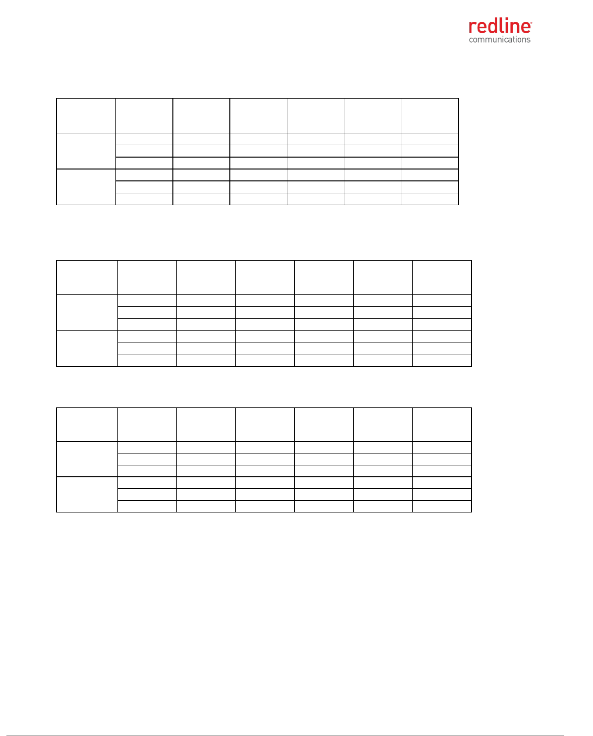
Table 32: 5.8 GHz: RF Power & EIRP: 5 MHz channel and PTP 10 dBi antenna
Modulation
Frequency,
MHz
Output
power on
ch0, dBm
Output
power on
ch0, dBm
Combined
power, dBm
Limit, dBm
Margin, dB
BPSK
5727.50
23.12
23.32
26.23
30.00
3.77
5790.00
22.10
22.35
25.24
30.00
4.76
5847.50
22.70
22.81
25.77
30.00
4.23
256-QAM
5727.50
23.30
23.55
26.44
30.00
3.56
5790.00
22.11
22.60
25.37
30.00
4.63
5847.50
22.71
22.99
25.86
30.00
4.14
Note: Total antenna gain includes 0.7 dB loss of the cable
Table 33: 5.8 GHz: RF Power & EIRP: 5 MHz channel and PTP 24 dBi antenna
Modulation
and data rate
Frequency,
MHz
Output power
on ch0, dBm
Output power
on ch0, dBm
Combined
power, dBm
Limit, dBm
Margin, dB
BPSK
5727.50
9.04
9.22
12.14
30.00
17.86
5790.00
22.10
22.35
25.24
30.00
4.76
5847.50
8.78
8.92
11.86
30.00
18.14
256-QAM
5727.50
9.08
9.23
12.17
30.00
17.83
5790.00
22.11
22.60
25.37
30.00
4.63
5847.50
8.82
8.98
11.91
30.00
18.09
Note: Total antenna gain includes 0.7 dB loss of the cable
Table 34: 5.8 GHz: RF Power & EIRP: 5 MHz channel and PTP 32 dBi antenna
Modulation
and data rate
Frequency,
MHz
Output power
on ch0, dBm
Output power
on ch0, dBm
Combined
power, dBm
Limit, dBm
Margin, dB
BPSK
5727.50
0.72
0.82
3.78
30.00
26.22
5790.00
19.94
19.95
22.96
30.00
7.04
5847.50
0.74
0.88
3.82
30.00
26.18
256-QAM
5727.50
0.73
0.82
3.79
30.00
26.21
5790.00
19.87
20.03
22.96
30.00
7.04
5847.50
0.77
0.81
3.80
30.00
26.20
Note: Total antenna gain includes 0.7 dB loss of the cable
RDL-3000 RMG3 MODULE PRODUCT MANUAL
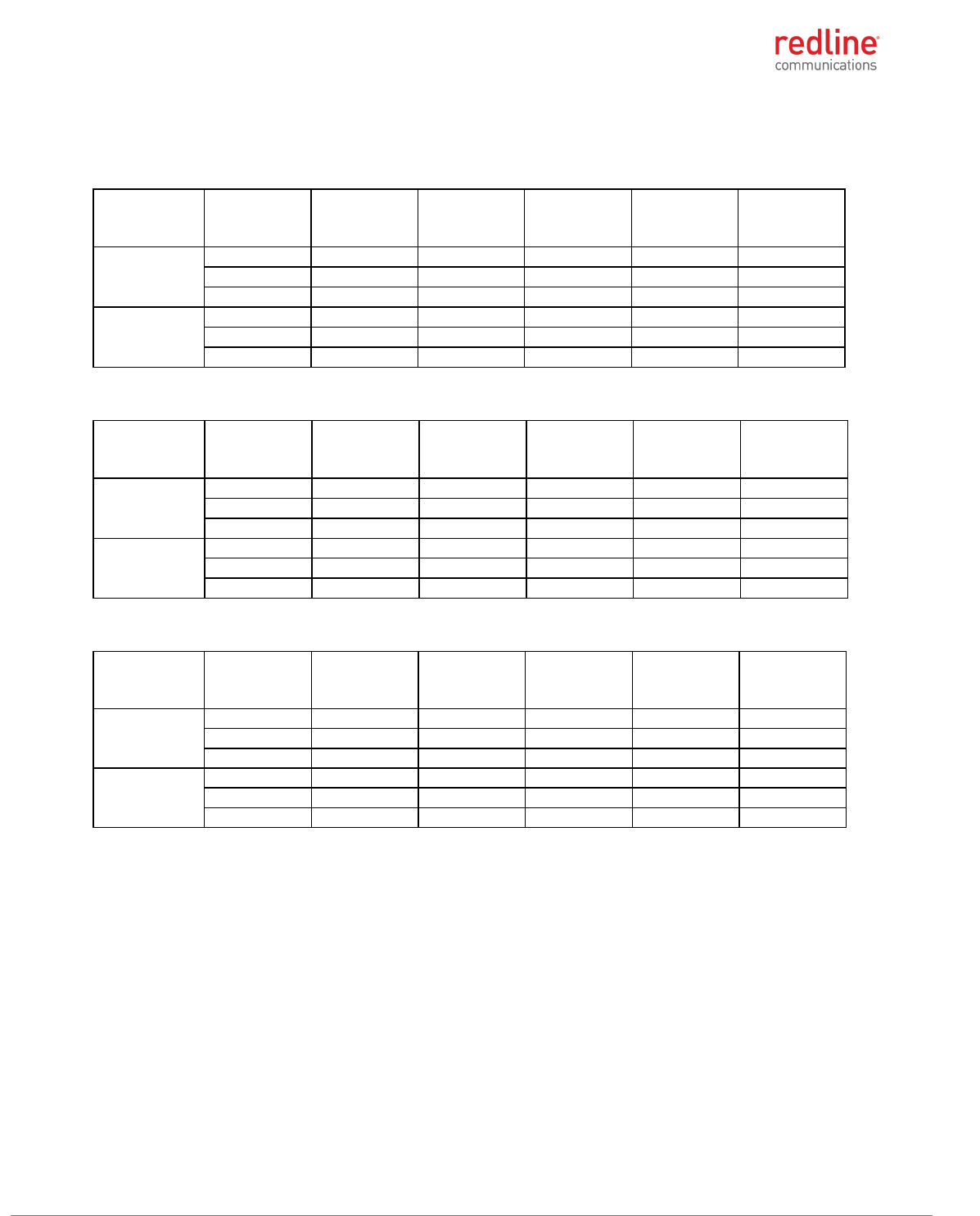
70-00184-10-01 Proprietary Redline Communications © 2017 Page 21 of 26 September 21, 2017
Table 35: 5.8 GHz: RF Power & EIRP: 10 MHz channel PTP 10 dBi antenna
Modulation
Frequency, MHz
Output power
on ch0, dBm
Output power
on ch0, dBm
Combined
power, dBm
Limit, dBm
Margin, dB
BPSK
5730.00
23.22
23.32
26.28
30.00
3.72
5790.00
22.75
22.87
25.82
30.00
4.18
5845.00
22.20
22.21
25.22
30.00
4.78
256-QAM
5730.00
23.21
23.29
26.26
30.00
3.74
5790.00
22.75
22.72
25.75
30.00
4.25
5845.00
22.24
22.23
25.25
30.00
4.75
Table 36: 5.8 GHz: RF Power & EIRP: 10 MHz channel PTP 24 dBi antenna
Modulation
Frequency, MHz
Output power
on ch0, dBm
Output power
on ch0, dBm
Combined
power, dBm
Limit, dBm
Margin, dB
BPSK
5730.00
9.05
9.18
12.13
30.00
17.87
5790.00
22.75
22.87
25.82
30.00
4.18
5845.00
8.27
8.41
11.35
30.00
18.65
256-QAM
5730.00
9.05
9.16
12.12
30.00
17.88
5790.00
22.75
22.72
25.75
30.00
4.25
5845.00
8.22
8.44
11.34
30.00
18.66
Table 37: 5.8 GHz: RF Power & EIRP: 10 MHz channel and PTP 32 dBi antenna
Modulation
Frequency, MHz
Output power
on ch0, dBm
Output power
on ch0, dBm
Combined
power, dBm
Limit, dBm
Margin, dB
BPSK
5730.00
0.66
0.66
3.67
30.00
26.33
5790.00
20.65
20.65
23.66
30.00
6.34
5845.00
-0.02
-0.03
2.99
30.00
27.01
256-QAM
5730.00
0.66
0.76
3.72
30.00
26.28
5790.00
20.71
20.86
23.80
30.00
6.20
5845.00
-0.03
0.10
3.05
30.00
26.95
RDL-3000 RMG3 MODULE PRODUCT MANUAL
70-00184-10-01 Proprietary Redline Communications © 2017 Page 22 of 26 September 21, 2017
Table 38: 5.8 GHz: RF Power & EIRP: 20 MHz channel PTP 10 dBi antenna
Modulation
Frequency, MHz
Output power
on ch0, dBm
Output power
on ch0, dBm
Combined
power, dBm
Limit, dBm
Margin, dB
BPSK
5735.00
23.42
23.55
26.50
30.00
3.50
5790.00
22.84
22.96
25.91
30.00
4.09
5840.00
22.56
22.86
25.72
30.00
4.28
256-QAM
5735.00
23.41
23.64
26.54
30.00
3.46
5790.00
22.75
23.95
26.40
30.00
3.60
5840.00
22.65
22.82
25.75
30.00
4.25
Table 39: 5.8 GHz: RF Power & EIRP: 20 MHz channel PTP 24 dBi antenna
Modulation
Frequency, MHz
Output power
on ch0, dBm
Output power
on ch0, dBm
Combined
power, dBm
Limit, dBm
Margin, dB
BPSK
5735.00
9.08
9.19
12.15
30.00
17.85
5790.00
22.84
22.96
25.91
30.00
4.09
5840.00
8.45
8.92
11.70
30.00
18.30
256-QAM
5735.00
9.11
9.18
12.16
30.00
17.84
5790.00
22.75
23.95
26.40
30.00
3.60
5840.00
8.45
8.92
11.70
30.00
18.30
Table 40: 5.8 GHz: RF Power & EIRP: 20 MHz channel and PTP 32 dBi antenna
Modulation
Frequency, MHz
Output power
on ch0, dBm
Output power
on ch0, dBm
Combined
power, dBm
Limit, dBm
Margin, dB
BPSK
5735.00
0.84
0.99
3.93
30.00
26.07
5790.00
20.98
20.90
23.95
30.00
6.05
5840.00
0.26
0.54
3.41
30.00
26.59
256-QAM
5735.00
0.86
0.98
3.93
30.00
26.07
5790.00
20.96
20.98
23.98
30.00
6.02
5840.00
0.27
0.56
3.43
30.00
26.57
RDL-3000 M2M Solutions
70-00184-10-01 Proprietary Redline Communications © 2017 Page 23 of 26 September 21, 2017
5 Regulatory Notices
5.1.1 FCC Notices
Deployment in USA
The following notices about deployment in the USA are included in training and
documentation provided to professional installers and operators of the final product:
1. The final product must be professionally installed.
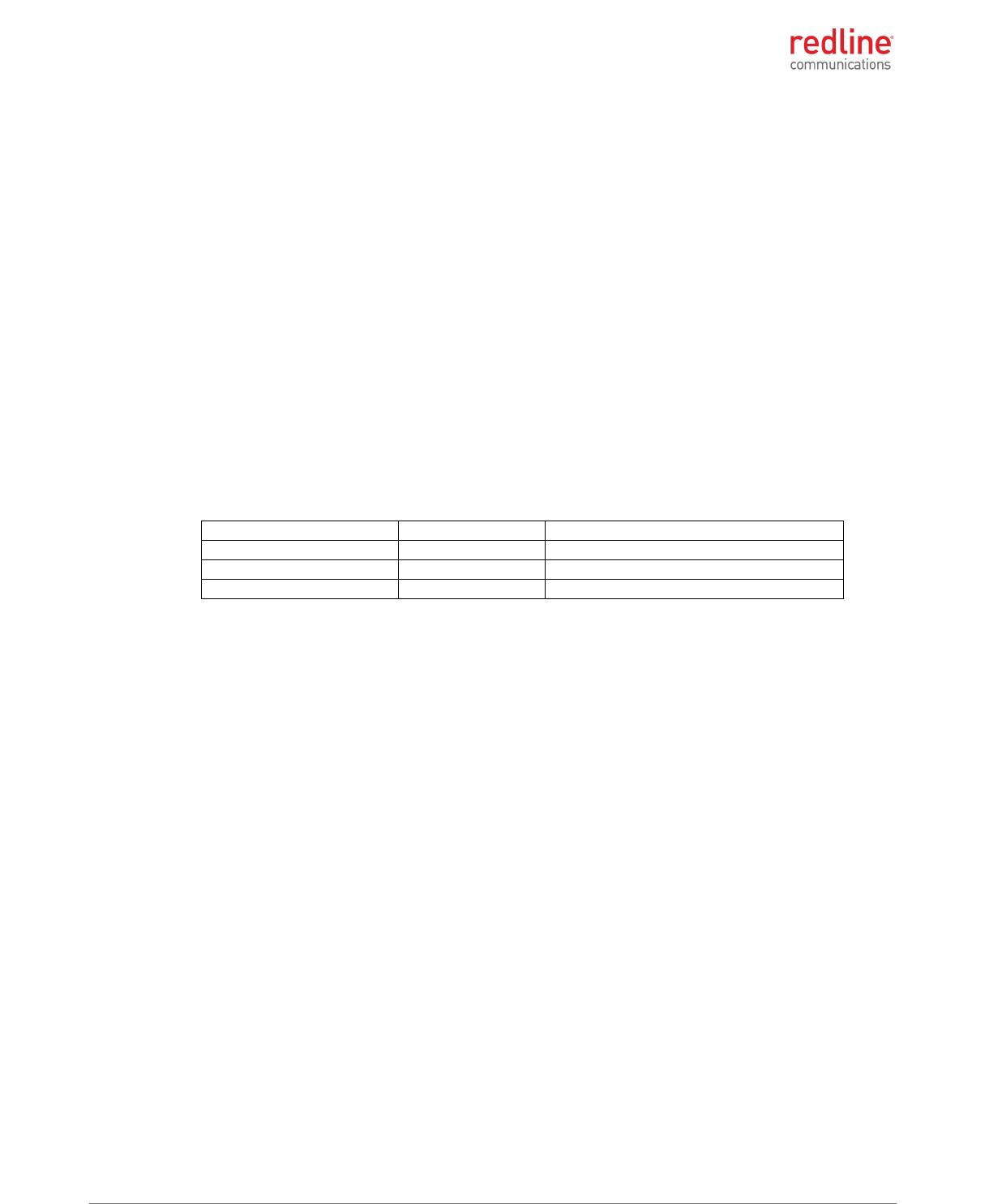
2. WARNING -- FCC RF Exposure Warnings
To satisfy FCC RF exposure requirements for RF transmitting devices, the following
distances should be maintained between the antenna of this device and persons
during device operation:
Table 41: FCC: RDL-3000-RMG3 Recommended Safe Distances
Frequency (MHz)
Deployment
Separation Distance
4900
PMP
270 cm (106.3") or more
5200
PMP
20 cm (7.8") or more
5800
PMP
20 cm (7.8") or more
5800
PTP
240 cm (94.5") or more
To ensure compliance, operation at closer than these distances is not
recommended. The antenna used for this transmitter must not be collocated in
conjunction with any other antenna or transmitter.
3. FCC Information to Users @ FCC 15.105:
NOTE: This equipment has been tested and found to comply with the limits for a
Class B digital device, pursuant to part 15 of the FCC Rules. These limits are
designed to provide reasonable protection against harmful interference in a
residential installation.
This equipment generates uses and can radiate radio frequency energy and, if not
installed and used in accordance with the instructions, may cause harmful
interference to radio communications. However, there is no guarantee that
interference will not occur in a particular installation. If this equipment does cause
harmful interference to radio or television reception, which can be determined by
turning the equipment off and on, the user is encouraged to try to correct the
interference by one or more of the following measures:
- Reorient or relocate the receiving antenna.
- Increase the separation between the equipment and receiver.
- Connect the equipment into an outlet on a circuit different from that to which the
receiver is connected.
- Consult the dealer or an experienced radio/TV technician for help.
Where DFS is required by regional regulations, this function is permanently enabled
at the factory and can not be disabled by the installer or end-user.
4. FCC Information to Users @ FCC 15.19:
This device complies with Part 15 of the FCC Rules. Operation is subject to the following
two conditions:
(1) This device may not cause harmful interference.
RDL-3000-RMG3 PRODUCT MANUAL
70-00184-10-01 Proprietary Redline Communications © 2017 Page 24 of 26 September 21, 2017
(2) This device must accept any interference received, including interference that
may cause undesired operation.
5. FCC Information to Users @ FCC 15.21:
Warning: Changes or modifications not expressly approved by Redline
Communications could void the user’s authority to operate the equipment.
5.1.2 Industry Canada Notices
Deployment in Canada
This Class B Digital apparatus meets all the requirements of the Canadian Interference-
Causing Equipment.
The following notices about deployment in Canada are included in training and
documentation provided to professional installers and operators of the final product:
1. The final product must be professionally installed.
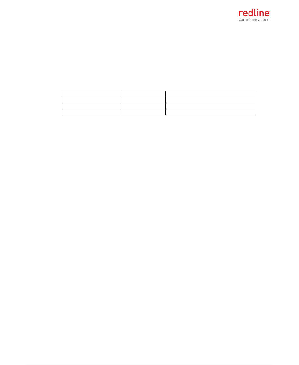
2. WARNING -- IC RF Exposure Warnings
To satisfy IC RF exposure requirements for RF transmitting devices, the following
distances should be maintained between the antenna of this device and persons
during device operation:
Table 42: IC: RDL-3000-RMG3 Recommended Safe Distances
Frequency (MHz)
Deployment
Separation Distance
4900
PMP
270 cm (106.3") or more
5800
PMP
20 cm (7.8") or more
5800
PTP
240 cm (94.5") or more
To ensure compliance, operation at closer than these distances is not
recommended. The antenna used for this transmitter must not be collocated in
conjunction with any other antenna or transmitter.
The RDL-3000-RMG3 has been designed to operate with an antenna having a
maximum gain of 32 dBi. Antenna having a higher gain is strictly prohibited per
regulations of Industry Canada. The required antenna impedance is 50 ohms.
This device has been designed to ensure that radio frequency emissions are maintained
within the band of operation under all normal operating conditions listed in this manual.
This device complies with Industry Canada license-exempt RSS standard(s). Operation
is subject to the following two conditions:
1. This device may not cause interference, and
2. This device must accept any interference, including interference that may cause
undesired operation of the device.
To reduce potential radio interference to other users, the antenna type and its gain
should be so chosen that the equivalent isotropic radiated power (EIRP) is not more than
that required for successful communication.
Users should also be advised that high-power radars are allocated as primary users (i.e.
priority users) of the bands 5250-5350 MHz and 5650-5850 MHz and that these radars
could cause interference and/or damage to LE-LAN devices.
Déploiement aux le Canada
Cet appareil numérique de la classe B est conforme à la norme NMB-003 du Canada.
RDL-3000-RMG3 PRODUCT MANUAL
70-00184-10-01 Proprietary Redline Communications © 2017 Page 25 of 26 September 21, 2017
Les avis suivants à propos du déploiement au Canada sont inclus dans la formation et la
documentation fournies aux installateurs professionnels et les opérateurs du produit
final:
1. Le produit final doit être installé par un professionnel.
2. AVERTISSEMENT - IC avertissements d'exposition RF
Pour satisfaire les exigences d’IC en ce qui a trait aux expositions aux RF pour RF
dispositifs de transmission, les distances suivantes doit être maintenue entre
l'antenne de ce dispositif et des personnes pendant le fonctionnement du dispositif:
Table 43: IC: RDL-3000-RMG3 distances de sécurité recommandées
Frequency (MHz)
Deployment
Separation Distance
4900
PMP
270 cm (106.3") ou plus
5800
PMP
20 cm (7.8") ou plus
5800
PTP
240 cm (94.5") ou plus
Le RDL-3000-RMG3 a été conçu pour fonctionner avec une antenne ayant un gain
maximal de 32 dBi. Antenne ayant un gain plus élevé est strictement interdite par les
règlements d'Industrie Canada. L'impédance d'antenne requise est de 50 ohms.
Ce dispositif a été conçu pour veiller à ce que les émissions de radiofréquences sont
maintenus dans la bande de fonctionnement dans toutes les conditions normales de
fonctionnement figurant dans ce manuel.
Cet appareil est conforme la norme d'Industrie Canada exempts de licence RSS (s). Son
fonctionnement est soumis aux deux conditions suivantes:
1. Cet appareil ne peut pas causer d'interférences, et
2. Cet appareil doit accepter toute interférence, y compris les interférences qui peuvent
causer un mauvais fonctionnement de l'appareil.
Pour réduire le potentiel d’interférence radio sur d’autres utilisateurs, le type d’antenne
et son gain doivent être choisies tel que la Puissance Isotrope Rayonnée Equivalente
(PIRE) ne dépasse pas le niveau nécessaire pour une communication efficace.
De plus, les utilisateurs devraient aussi être avisés que les utilisateurs de radars de
haute puissance sont désignés utilisateurs principaux (c.-à-d., qu’ils ont la priorité) pour
les bandes 5 250-5 350 MHz et 5 650-5 850 MHz et que ces radars pourraient causer
du brouillage et/ou des dommages aux dispositifs LAN-EL.

RDL-3000 M2M Solutions
70-00184-10-01 Proprietary Redline Communications © 2017 Page 26 of 26 September 21, 2017
302 Town Centre Markham, Ontario Canada L3R 0E8
www.rdlcom.com