Reliant Octel 200 And 300 Message Servers Pb6001401 Users Manual
PB6001401 to the manual cad28a4f-625e-489d-9eff-17a69c0bd800
2015-02-06
: Reliant Reliant-Octel-200-And-Octel-300-Message-Servers-Pb6001401-Users-Manual-522860 reliant-octel-200-and-octel-300-message-servers-pb6001401-users-manual-522860 reliant pdf
Open the PDF directly: View PDF ![]() .
.
Page Count: 668 [warning: Documents this large are best viewed by clicking the View PDF Link!]

Installation and Maintenance
Octel 200 and Octel 300
Message Servers
IV
Installation
and Maintenance Manual
Serenade 2.0 and Serenade 3.0
July 1998
Lucent Technologies
Octel Messaging Division
1001 Murphy Ranch Road
Milpitas, CA 95035-7912 USA

Your
comments are welcome. They can assist us in improving our products. Please address your
comments to techpubs@octel.com or to the EMG T
echnical Publications Manager at
Lucent T
echnologies
Octel Messaging Division (OMD)
1001 Murphy Ranch Road
Milpitas, CA 95035-7912
USA
408-324-2000
www.octel.com
This manual contains confidential and proprietary information of Octel Communications Corporation, a
subsidiary of Lucent T
echnologies and is protected by the copyright laws of the United States,
international copyright treaties, and all other applicable national laws. Any unauthorized use,
reproduction, or transfer of any information in this manual is strictly prohibited.
Copyright 1998 by
Octel Communications Corporation, a subsidiary of Lucent Technologies. (subject to limited distribution
and restricted disclosure). All Rights Reserved.
This manual contains information regarding technology that is protected under one or more of the
following United States patents: Nos. 4,371,752; 4,580,012; 4,580,016; 4,581,486; 4,585,906; 4,602,129;
4,640,991; 4,652,700; 4,757,525; 4,471,807; 4,747,124, 4,783,796, and others; certain foreign patents,
and other pending United States and foreign patents.
Restricted Rights Notice
Use, duplication, or disclosure by the United States Government is subject to restrictions as set forth in
subparagraphs (c) (1) of the Commercial Computer Software – Restricted Rights clause at F
AR Section
52.227-19 and restrictions set forth in the accompanying end user agreement, or (c)(1)(ii) of the Rights in
T
echnical Data and Computer Software clause at DFARS Section 252.227-7013, whichever is applicable.
Unpublished – rights reserved under the copyright laws of the United States. Lucent T
echnologies Octel
Messaging Division (OMD), 1001 Murphy Ranch Road, Milpitas, CA 95035-7912, USA.
All trademarks identified by the
or
symbol are trademarks or registered trademarks, respectively
, of
Octel Communications Corporation, a subsidiary of Lucent Technologies. All other trademarks belong to
their respective owners.
This 3-volume Installation and Maintenance Manual supports the Octel 200 and Octel 300.
Part Number PB60014–01
July 1998
Printed in USA

Octel
Overture 200/300 Serenade 3.0
PB60014–01
This
equipment complies with Part 68 of the FCC rules. On the back of this equipment is a label that
contains, among other information, the FCC registration number and ringer equivalence number (REN)
for this equipment. If requested, this information must be provided to the telephone company
.
The REN is used to determine the quantity of devices that can be connected to the telephone line.
Excessive RENs on the telephone line may result in the device not ringing in response to an incoming
call. In most but not all areas, the sum of the RENs should not exceed five(5.0). T
o be certain of the
number of devices that may be connected to the line, as determined by the total RENs contact the
telephone company for the maximum REN in your area.
If this equipment causes harm to the telephone network, the telephone, the telephone company will notify
you in advance that temporary discontinuance of service may be required. If advance notice is not
practical, the telephone company will notify the customer as soon as possible. Also, you will be advised
of your right to file a complaint with the FCC.
The telephone company may make changes in its facilities, equipment, operations, or procedures that
could af
fect the operation of the equipment. If this happens, the telephone company will provide advance
notice in order for you to make the necessary modifications in order to maintain uninterrupted service.
If trouble is experienced with the equipment, please contact:
T
echnical Assistance Center (T
AC) The T
AC supports distributors, GBS customers, and direct field
service engineers in the United States of America.
408-922-1822
If the trouble is causing harm to the network, the telephone company may request that you remove the
equipment from the network until the problem is resolved.
Repairs should be performed by Octel Communications Corporation or an authorized representative of
Octel Communications Corporation or the warranty or service agreement could be void.
This equipment cannot be used on telephone company-provided coin service.
Connection to Party Line Service is subject to state tarif
fs.
The T
elephone Consumer Protection Act of 1991 makes it unlawful for any person to use a computer or
other electronic device to send any message via a telephone facsimile machine unless such message
clearly contains, in a mar
gin at the top or bottom of each transmitted page or on the first page of the
transmission, the date and time it is sent and an identification of the business, other entity
, or individual
sending the message and the telephone number of the sending machine or such business, other entity
, or
individual.
If
the O200 or O300 is to be used with a leased system, permission of the owner should be requested
before its connection. The O200 / O300 when using either the APIC or NPIC is intended only for
connection to a registered PBX and never directly to the network.

Octel
Overture 200/300 Serenade 3.0
PB60014–01
This
equipment has been tested and found to comply with the limits for a Class A digital device pursuant
to Part 15 FCC Rules. These limits are designed to provide reasonable protection against harmful
interference when this equipment is operated in a commercial environment. This equipment generates,
uses, and can radiate radio frequency ener
gy and, if not installed and used in accordance with the
instruction manual, may cause harmful interference to radio communications. Operation of this
equipment in a residential area is likely to cause harmful interference, in which case the user will be
required to correct the interference at his/her own expense. Any changes or modifications to this
equipment not expressly approved by Octel Communications Corporation may void compliance with
FCC requirements and the user
’
s authority to operate the equipment.

Octel
Overture 200/300 Serenade 3.0
PB60014–01
Introduction
The
Octel Overture 300 message server is a 32 to 128 port voice messaging system and the Octel
Overture 200 message server is a 4 to 64 port voice messaging system. When installed at a customer
’s
site, the message server attaches to the extension lines of a P
ABX or directly to the public network via
Direct Exchange Lines.
This document section describes certain operation requirements which must be complied with in the
United Kingdom to allow connection of the message server to a P
ABX or directly to the public network.
Failure to comply to the requirements described in this document may invalidate the
compliance of the apparatus, thus prohibiting its connection to the network in the United
Kingdom.
The approval of this apparatus will be invalidated if it is used with internal software not
formally accepted by BABT. The internal software is not accessible or alterable by the user.
There are no user serviceable parts, or user controls, in the system enclosure.
Interconnection directly, or by way of other apparatus, of Octel Overture 200 ports or
Octel Overture 300 ports with ports which do not comply with the requirements of BS6301
may produce hazardous conditions on the BT network. Advice should be obtained from
a competent engineer before such a connection is made.
When network addresses (telephone numbers) are manually entered into the system for
autoĆcalling, care should be exercised to ensure that the addresses are correct
This apparatus is not to be used for making calls to the BT emergency service.
Ringer Equivalence
Under
normal operating conditions, this apparatus is not meant to form part of a multiple installation; the
port interfaces are the sole termination of the line. Additional apparatus, BT or otherwise, must not be
connected between this equipment and the P
ABX line or public network.

Octel
Overture 200/300 Serenade 3.0
PB60014–01
Functions
The
Octel Overture 200 and the Octel Overture 300 message servers have the following functions.
-
Automatically answers calls redirected on no answer or busy conditions.
-
Interrogates the caller for any messages.
-
Stores the message.
-
Forwards the message as and when appropriate.
-
When connected to a PBX, the ability to answer and transfer a call.
-
The option to place outgoing calls (through a PBX, or directly into the public network) for the
purpose of delivering messages.
And the following outcalling functions.
-
The system operator can store predetermined numbers to be dialed for outcalls within the message
server
. These numbers include pauses to allow for secondary proceed indications.
-
The message server automatically schedules multiple call repeat attempts as required for
unsuccessful outcalls. The times between calls and the number of repeat attempts conform to the
requirements of the appropriate UK specifications.
-
The message server is suitable for connection to a P
ABX that returns secondary proceed indication
through the use of dialing pauses, as described above. For PABXs that do not return secondary
proceed indication, the pauses are not used.
Pay Phones
The
Octel Overture 200 and the Octel Overture 300 message servers are not suitable as an extension to a
pay phone.
Keys
When the message server is in operation, and is not being serviced by maintenance personnel, the key to
the enclosure shall be removed to prevent user (operator) access.
Outcall Configuration Requirements
The
Octel Overture 200 and the Octel Overture 300 message servers have the capability to outcall via the
P
ABX or directly to the public network via Direct Exchange Lines. The message server uses
multi-frequency dialing. Loop disconnect dialing is not supported.
" A
Failure to comply to the requirements described in this document may invalidate the
compliance of the apparatus, thus prohibiting its connection to the network in the
United Kingdom.
System Parameters
The
following System Parameters are particular to the requirements for the UK. The installation engineer
must verify that these parameters have the following assignments:

Octel
Overture 200/300 Serenade 3.0
PB60014–01
68 NET:REMOTE DELIVERY ATTEMPT LIMIT 20
69 NET:REMOTE DELAY BEFORE RETRY (MINUTES) 10
Delays
in dialing strings (D character) between the P
ABX access code and the rest of the digits
must be between 3.5 and 8 seconds. Set D character timing in System Parameter 28 —
“D”
CHARACTER DELAY TIME.
INFORMATION
Table Indices
The
following
INFORMATION Table
indices are particular to the requirements for the UK. The installation
engineer must verify that these indices have the following assignments:
15 OFFSITE SPEAK TIMES 4
16 OFFSITE SPEAK DELAY 5
The
values for
INFORMATION Table
Indices 15 and 16 must be set so that the total of
fhook time is less
than 60 seconds. The above values meet that specification.

Octel
Overture 200/300 Serenade 3.0
PB60014–01
! " #
The
Industry Canada label identifies certified equipment. This certification means that the equipment
meets certain telecommunications network protective, operational, and safety requirements. Industry
Canada does not guarantee the equipment will operate to the user
’
s satisfaction.
Before installing this equipment, users should ensure that it is permissible to be connected to the facilities
of the local telecommunications company
. The equipment must also be installed using an acceptable
method of connection. In some cases, the company’
s inside wiring associated with a single line individual
service may be extended by means of a certified connector assembly (telephone extension cord). The
customer should be aware that compliance with the above conditions may not prevent degradation of
service in some situations. Communication cables provided by the user to connect to the
telecommunications network must be not less than 26 A
WG copper
.
Repairs should be performed by Octel Communications Corporation or an authorized representative of
Octel Communications Corporation or the warranty or service agreement could be void. In the event that
this equipment malfunctions, the telecommunications company may request that the equipment be
disconnected.
Users should ensure for their own protection that the electrical ground connections of the power utility
,
telephone lines, and internal metallic water pipe system, if present, are connected together
. This
precaution may be particularly important in rural areas.
Users should not attempt to make such connections themselves, but should contact the appropriate
electric inspection authority, or electrician, as appropriate. The equipment is installed by trained
personnel.
The
Load Number
(LN) assigned to each terminal device denotes the percentage of the total load to be
connected to a telephone loop which is used by the device, to prevent overloading. The termination on a
loop may consist of any combination of devices subject only to the requirement that the total of the Load
Numbers of all the devices does not exceed 100.
The load number of this product O200 / O300 is 19.
This
Class A digital apparatus meets all the requirements of the Canadian Interference-Causing
Equipment Regulations (ICES).

Octel
Overture 200/300 Serenade 3.0
PB60014–01
Industrie
Canada:
Cet
appareil numérique de la classe A respecte toutes les exigences du Reglement sur le matériel
brouilleur du Canada (ICES).
A
VIS:
L
’étiquette de L
’Industrie Canada identifie le matériel homologué. Cette étiquette certifie que le
matériel est conforme à certaines normes de protection, d’exploitation et de sécurité des réseaux de
télécommunications. Industrie Canada n’assure toutefois pas que le matériel fonctionnera à la
satisfaction de l’utilisateur
.
A
vant d’installer ce matériel, l’utilisateur doit s’assurer qu’il est permis de le raccorder aux installations
de l’entreprise locale de télécommunication. Le matériel doit également être installé en suivant une
méthode acceptée de raccordement. L’abonné ne doit pas oublier qu’il est possible que la conformité aux
conditions énoncées ci–dessous n’empechent pas la dégradation du service dans certaines situations.
Les réparations de matériel homologué doivent être ef
fectuées par un centre d’entretien canadien autorisé
designé par le fournisseur. La compagnie de télécommunications peut demander à l’utilisateur de
débrancher un appareil à la suite de reparations où de modifications ef
fectuées par l’utilisateur ou à cause
de mauvais fonctionnement.
Pour sa propre protection, l’utilisateur doit s’assurer que tous les fils de mise à terre de la source
d’éner
gie électrique, les lignes téléphoniques et les canalisations d’eau métalliques, s’il y en a, sont
raccordées ensembles. Cette précaution est particulierement importante dans les régions rurales.
AVERTISSEMENT: L
’utilisateur ne doit pas tenter de faire ces raccordements de lui–même; il doit
avoir recours à un service d’inspection des installations électriques, ou à un électricien, selon le cas.
La câble de télécommunications qui sont fournis par l’utilisateur ne doivent pas être infériers à 26 A
WG
de cuivre.
L’
Indice de Charge
(IC) assigné à chaque dispositif terminal indique, pour éviter toute surchar
ge, le
pourcentage de la charge totale qui peut être racordée à un circuit téléphonique bouclé utilisé par ce
dispositif. La terminaison du circuit bouclé peut être constituée de n’importe quelle combinaison de
dispositifs, pourvu que la somme des indices de char
ge de l’ensemble des dispositifs ne dépasse pas 100.
L
’indice de char
ge de ce produit O200 / O300 est 19.

Octel
Overture 200/300 Serenade 3.0
PB60014–01
Octel Overture 200/300 !
"!
1.1 Understanding
the INST
ALL Program
1-1.
. . . . . . . . . . . . . . . . . . . . . . . . . . . . . . . . . . . . . . . . . . . . . . . . . . . . . . . . .
1.2 Using INSTALL 1-4.
. . . . . . . . . . . . . . . . . . . . . . . . . . . . . . . . . . . . . . . . . . . . . . . . . . . . . . . . . . . . . . . . . . . . . . . . . . . . .
1.3 Answering
Questions in INST
ALL 1-7.
. . . . . . . . . . . . . . . . . . . . . . . . . . . . . . . . . . . . . . . . . . . . . . . . . . . . . . . . . . . . .
1.4 Answering
Questions About Other T
elephone Systems
1-24.
. . . . . . . . . . . . . . . . . . . . . . . . . . . . . . . . . . . . . . . . .
1.5 Exiting
Before the INST
ALL is Complete
1-26.
. . . . . . . . . . . . . . . . . . . . . . . . . . . . . . . . . . . . . . . . . . . . . . . . . . . . . .
#
2.1 Hardware 2-1.
. . . . . . . . . . . . . . . . . . . . . . . . . . . . . . . . . . . . . . . . . . . . . . . . . . . . . . . . . . . . . . . . . . . . . . . . . . . . . . . . . .
$
3.1 How
the Octel Overture 200/300 W
orks with the Phone System
3-1.
. . . . . . . . . . . . . . . . . . . . . . . . . . . . . . . . . . .
3.2 Determining Necessary Changes 3-5.
. . . . . . . . . . . . . . . . . . . . . . . . . . . . . . . . . . . . . . . . . . . . . . . . . . . . . . . . . . . . .
3.3 Changes
to Central Of
fice T
runking 3-6.
. . . . . . . . . . . . . . . . . . . . . . . . . . . . . . . . . . . . . . . . . . . . . . . . . . . . . . . . . . .
3.4 Phone
System Configuration
3-8.
. . . . . . . . . . . . . . . . . . . . . . . . . . . . . . . . . . . . . . . . . . . . . . . . . . . . . . . . . . . . . . . . .
3.5 Implementing
the Octel Overture 200/300 on PBXs without DIL Feature
3-12.
. . . . . . . . . . . . . . . . . . . . . . . . . . .
4.1 Receiving
the Equipment
4-1.
. . . . . . . . . . . . . . . . . . . . . . . . . . . . . . . . . . . . . . . . . . . . . . . . . . . . . . . . . . . . . . . . . . . .
4.2 Installation
Requirements
4-4.
. . . . . . . . . . . . . . . . . . . . . . . . . . . . . . . . . . . . . . . . . . . . . . . . . . . . . . . . . . . . . . . . . . . .
4.3 PBX
Preparation
4-15.
. . . . . . . . . . . . . . . . . . . . . . . . . . . . . . . . . . . . . . . . . . . . . . . . . . . . . . . . . . . . . . . . . . . . . . . . . .
4.4 Terminal
Communications
4-16.
. . . . . . . . . . . . . . . . . . . . . . . . . . . . . . . . . . . . . . . . . . . . . . . . . . . . . . . . . . . . . . . . . .
4.5 Pin Assignments for Message Server Cards and Ports 4-21.
. . . . . . . . . . . . . . . . . . . . . . . . . . . . . . . . . . . . . . . . . .
4.6 Communicating
with the Message Server
4-35.
. . . . . . . . . . . . . . . . . . . . . . . . . . . . . . . . . . . . . . . . . . . . . . . . . . . . .
4.7 Octel
Overture 200/300 HarDware Installation
4-37.
. . . . . . . . . . . . . . . . . . . . . . . . . . . . . . . . . . . . . . . . . . . . . . . . .
4.8 Rack
Mount Installation, Octel Overture 300
4-40.
. . . . . . . . . . . . . . . . . . . . . . . . . . . . . . . . . . . . . . . . . . . . . . . . . . .
4.9 Software
Installation
4-44.
. . . . . . . . . . . . . . . . . . . . . . . . . . . . . . . . . . . . . . . . . . . . . . . . . . . . . . . . . . . . . . . . . . . . . . .
4.10 Connecting
the Phone System to the Octel Overture 200/300
4-45.
. . . . . . . . . . . . . . . . . . . . . . . . . . . . . . . . .
4.11 Octel
Overture 200/300 T
esting 4-50.
. . . . . . . . . . . . . . . . . . . . . . . . . . . . . . . . . . . . . . . . . . . . . . . . . . . . . . . . . . . . . .
4.12 Testing
the Installation and T
elephone Changes
4-58.
. . . . . . . . . . . . . . . . . . . . . . . . . . . . . . . . . . . . . . . . . . . . . . .

Octel
Overture 200/300 Serenade 3.0
PB60014–01
""!
(continued)
" "!
5.1 Overview 5-1.
. . . . . . . . . . . . . . . . . . . . . . . . . . . . . . . . . . . . . . . . . . . . . . . . . . . . . . . . . . . . . . . . . . . . . . . . . . . . . . . . . .
5.2 Listing
and Clearing Reports
5-2.
. . . . . . . . . . . . . . . . . . . . . . . . . . . . . . . . . . . . . . . . . . . . . . . . . . . . . . . . . . . . . . . . .
5.3 System
Performance Report
5-5.
. . . . . . . . . . . . . . . . . . . . . . . . . . . . . . . . . . . . . . . . . . . . . . . . . . . . . . . . . . . . . . . . .
5.4 Network
T
raf
fic Report
5-16.
. . . . . . . . . . . . . . . . . . . . . . . . . . . . . . . . . . . . . . . . . . . . . . . . . . . . . . . . . . . . . . . . . . . . .
5.5 User Message Statistics 5-21.
. . . . . . . . . . . . . . . . . . . . . . . . . . . . . . . . . . . . . . . . . . . . . . . . . . . . . . . . . . . . . . . . . . . .
5.6 User
Calling Statistics
5-23.
. . . . . . . . . . . . . . . . . . . . . . . . . . . . . . . . . . . . . . . . . . . . . . . . . . . . . . . . . . . . . . . . . . . . .
5.7 Disk
Usage Report
5-25.
. . . . . . . . . . . . . . . . . . . . . . . . . . . . . . . . . . . . . . . . . . . . . . . . . . . . . . . . . . . . . . . . . . . . . . . .
5.8 Port Statistics 5-27.
. . . . . . . . . . . . . . . . . . . . . . . . . . . . . . . . . . . . . . . . . . . . . . . . . . . . . . . . . . . . . . . . . . . . . . . . . . . .
5.9 Mailbox Usage 5-31.
. . . . . . . . . . . . . . . . . . . . . . . . . . . . . . . . . . . . . . . . . . . . . . . . . . . . . . . . . . . . . . . . . . . . . . . . . . .
5.10 User
Status Detail
5-32.
. . . . . . . . . . . . . . . . . . . . . . . . . . . . . . . . . . . . . . . . . . . . . . . . . . . . . . . . . . . . . . . . . . . . . . . .
5.11 Integration
Calling Statistics
5-33.
. . . . . . . . . . . . . . . . . . . . . . . . . . . . . . . . . . . . . . . . . . . . . . . . . . . . . . . . . . . . . . . .
5.12 System Performance by COS 5-35.
. . . . . . . . . . . . . . . . . . . . . . . . . . . . . . . . . . . . . . . . . . . . . . . . . . . . . . . . . . . . . . .
" " !
6.1 Command
Summary
6-1.
. . . . . . . . . . . . . . . . . . . . . . . . . . . . . . . . . . . . . . . . . . . . . . . . . . . . . . . . . . . . . . . . . . . . . . . .
6.2 Diagnostics 6-17
. . . . . . . . . . . . . . . . . . . . . . . . . . . . . . . . . . . . . . . . . . . . . . . . . . . . . . . . . . . . . . . . . . . . . . . . . . . . . . . .
6.3 Application Delays 6-43.
. . . . . . . . . . . . . . . . . . . . . . . . . . . . . . . . . . . . . . . . . . . . . . . . . . . . . . . . . . . . . . . . . . . . . . . . .
6.4 Message
Block and Message Purge
6-52.
. . . . . . . . . . . . . . . . . . . . . . . . . . . . . . . . . . . . . . . . . . . . . . . . . . . . . . . . .
" !
7.1 LOG
Command
7-1.
. . . . . . . . . . . . . . . . . . . . . . . . . . . . . . . . . . . . . . . . . . . . . . . . . . . . . . . . . . . . . . . . . . . . . . . . . . . .
7.2 Call Processing Trace (CPT) 7-5.
. . . . . . . . . . . . . . . . . . . . . . . . . . . . . . . . . . . . . . . . . . . . . . . . . . . . . . . . . . . . . . . . .
7.3 Call
Detail Record Log
7-22.
. . . . . . . . . . . . . . . . . . . . . . . . . . . . . . . . . . . . . . . . . . . . . . . . . . . . . . . . . . . . . . . . . . . . .
7.4 Namesend Activity T
race Log
7-40.
. . . . . . . . . . . . . . . . . . . . . . . . . . . . . . . . . . . . . . . . . . . . . . . . . . . . . . . . . . . . . . .
7.5 Moves,
Add, and Changes Log
7-43.
. . . . . . . . . . . . . . . . . . . . . . . . . . . . . . . . . . . . . . . . . . . . . . . . . . . . . . . . . . . . . .
7.6 Server Activity T
race Log
7-50.
. . . . . . . . . . . . . . . . . . . . . . . . . . . . . . . . . . . . . . . . . . . . . . . . . . . . . . . . . . . . . . . . . . .
Appendix A Call-Processing Trace Activities 7A-1.
. . . . . . . . . . . . . . . . . . . . . . . . . . . . . . . . . . . . . . . . . . . . . . . . . . . . . . . . . . . .
" $!" ! !
8.1 Boot ROM Diagnostics 8-1.
. . . . . . . . . . . . . . . . . . . . . . . . . . . . . . . . . . . . . . . . . . . . . . . . . . . . . . . . . . . . . . . . . . . . . .
8.2 Hardware Errors 8-4.
. . . . . . . . . . . . . . . . . . . . . . . . . . . . . . . . . . . . . . . . . . . . . . . . . . . . . . . . . . . . . . . . . . . . . . . . . . . .
8.3 Traffic
Peg Count T
able 8-37.
. . . . . . . . . . . . . . . . . . . . . . . . . . . . . . . . . . . . . . . . . . . . . . . . . . . . . . . . . . . . . . . . . . . . .
" # "
9.1 Hardware
Maintenance and Diagrams
9-1.
. . . . . . . . . . . . . . . . . . . . . . . . . . . . . . . . . . . . . . . . . . . . . . . . . . . . . . . . .
9.2 Hardware
Replacement Guidelines
9-12.
. . . . . . . . . . . . . . . . . . . . . . . . . . . . . . . . . . . . . . . . . . . . . . . . . . . . . . . . . .
9.3 Message Server Assembly Descriptions and Part Numbers 9-56.
. . . . . . . . . . . . . . . . . . . . . . . . . . . . . . . . . . . . .

Octel
Overture 200/300 Serenade 3.0
PB60014–01
Table of Contents
(continued)
Chapter 10 Digital Trunk Interface Card (DTIC)
10.1 Digital
T
runk Interface Card (DTIC) Overview 10-1.
. . . . . . . . . . . . . . . . . . . . . . . . . . . . . . . . . . . . . . . . . . . . . . . . . .
10.2 How
to Configure the DTIC
10-3.
. . . . . . . . . . . . . . . . . . . . . . . . . . . . . . . . . . . . . . . . . . . . . . . . . . . . . . . . . . . . . . . . .
10.3 Troubleshooting
and Maintenance
10-10.
. . . . . . . . . . . . . . . . . . . . . . . . . . . . . . . . . . . . . . . . . . . . . . . . . . . . . . . . . .
Chapter 11 LAN Card
11.1 Overview 11-1.
. . . . . . . . . . . . . . . . . . . . . . . . . . . . . . . . . . . . . . . . . . . . . . . . . . . . . . . . . . . . . . . . . . . . . . . . . . . . . . . . .
11.2 Installing
and Configuring the LAN Card
11-2.
. . . . . . . . . . . . . . . . . . . . . . . . . . . . . . . . . . . . . . . . . . . . . . . . . . . . . .
11.3 Testing
the LAN Card
11-6.
. . . . . . . . . . . . . . . . . . . . . . . . . . . . . . . . . . . . . . . . . . . . . . . . . . . . . . . . . . . . . . . . . . . . . .
11.4 Taking
the LAN Card Out of Service
11-10.
. . . . . . . . . . . . . . . . . . . . . . . . . . . . . . . . . . . . . . . . . . . . . . . . . . . . . . . . .
Appendix A
Internet Addressing
11A-1.
. . . . . . . . . . . . . . . . . . . . . . . . . . . . . . . . . . . . . . . . . . . . . . . . . . . . . . . . . . . . . . . . . . . . . . .
Appendix B
Simple Network Management Protocol (SNMP)
11B-1.
. . . . . . . . . . . . . . . . . . . . . . . . . . . . . . . . . . . . . . . . . . . . . . .
Appendix C Octel Private MIB 11C-1.
. . . . . . . . . . . . . . . . . . . . . . . . . . . . . . . . . . . . . . . . . . . . . . . . . . . . . . . . . . . . . . . . . . . . . . . .
Chapter 12 Procedures
12.1 Electronic
Feature Delivery
12-1.
. . . . . . . . . . . . . . . . . . . . . . . . . . . . . . . . . . . . . . . . . . . . . . . . . . . . . . . . . . . . . . . . .
12.2 Floppy Diskette Backup Procedures 12-3.
. . . . . . . . . . . . . . . . . . . . . . . . . . . . . . . . . . . . . . . . . . . . . . . . . . . . . . . . . .
12.3 Floppy Diskette Restore Procedures 12-22.
. . . . . . . . . . . . . . . . . . . . . . . . . . . . . . . . . . . . . . . . . . . . . . . . . . . . . . . .
12.4 Floppy Directory 12-39.
. . . . . . . . . . . . . . . . . . . . . . . . . . . . . . . . . . . . . . . . . . . . . . . . . . . . . . . . . . . . . . . . . . . . . . . . . .
12.5 Errors 12-40
. . . . . . . . . . . . . . . . . . . . . . . . . . . . . . . . . . . . . . . . . . . . . . . . . . . . . . . . . . . . . . . . . . . . . . . . . . . . . . . . . . . .
12.6 Hard Disk Procedures 12-41.
. . . . . . . . . . . . . . . . . . . . . . . . . . . . . . . . . . . . . . . . . . . . . . . . . . . . . . . . . . . . . . . . . . . .
12.7 Adding
Languages
12-71.
. . . . . . . . . . . . . . . . . . . . . . . . . . . . . . . . . . . . . . . . . . . . . . . . . . . . . . . . . . . . . . . . . . . . . . . .

Octel
Overture 200/300 Serenade 3.0
PB60014–01
Octel Overture 200/300 Installation and Maintenance Manual
volume
Table of Contents Ċ Figures
Chapter 1 INSTALL
1-1 Order
of Questions and Associated T
ables in the INSTALL Program
1-2.
. . . . . . . . . . . . . . . . . . . . . . . . . . . . . . .
Chapter 2 Hardware
2-1 Octel
Overture 200 Cabinet Shelf Structure, From the Front
2-4.
. . . . . . . . . . . . . . . . . . . . . . . . . . . . . . . . . . . . . .
2-2 Octel
Overture 200 Cabinet, Inside Front V
iew 2-5.
. . . . . . . . . . . . . . . . . . . . . . . . . . . . . . . . . . . . . . . . . . . . . . . . . .
2-3 Octel
Overture 200 Cabinet, Rear V
iew 2-6.
. . . . . . . . . . . . . . . . . . . . . . . . . . . . . . . . . . . . . . . . . . . . . . . . . . . . . . . .
2-4 Octel
Overture 200 Cabinet, Inside Rear V
iew 2-7.
. . . . . . . . . . . . . . . . . . . . . . . . . . . . . . . . . . . . . . . . . . . . . . . . . .
2-5 Octel
Overture 300 Cabinet Shelf Structure, From the Front
2-10.
. . . . . . . . . . . . . . . . . . . . . . . . . . . . . . . . . . . . .
2-6 Octel
Overture 300 Cabinet, Inside Front V
iew 2-11.
. . . . . . . . . . . . . . . . . . . . . . . . . . . . . . . . . . . . . . . . . . . . . . . . .
2-7 Octel
Overture 300 Cabinet, Rear V
iew 2-12.
. . . . . . . . . . . . . . . . . . . . . . . . . . . . . . . . . . . . . . . . . . . . . . . . . . . . . . .
2-8 Octel
Overture 300 Cabinet, Inside Rear V
iew 2-13.
. . . . . . . . . . . . . . . . . . . . . . . . . . . . . . . . . . . . . . . . . . . . . . . . .
Chapter 3 Preparing the Phone System
3-1 Octel
Overture 200/300 Connection to Phone System
3-1.
. . . . . . . . . . . . . . . . . . . . . . . . . . . . . . . . . . . . . . . . . . .
3-2 All
Incoming Lines Directed to the Octel Overture 200/300
3-3.
. . . . . . . . . . . . . . . . . . . . . . . . . . . . . . . . . . . . . . .
3-3 Incoming
Calls Split Between Console and the Octel Overture 200/300
3-3.
. . . . . . . . . . . . . . . . . . . . . . . . . . . .
3-4 Sample
Agency Letter for PE Changes
3-7.
. . . . . . . . . . . . . . . . . . . . . . . . . . . . . . . . . . . . . . . . . . . . . . . . . . . . . . . .
3-5 Service
Provider Letter
3-11.
. . . . . . . . . . . . . . . . . . . . . . . . . . . . . . . . . . . . . . . . . . . . . . . . . . . . . . . . . . . . . . . . . . . . .
3-6 Directing
Incoming Calls to the Octel Overture 200/300 When the PBX Does Not Of
fer a DIL Feature
3-12.
.
Chapter 4 Installation
4-1 Octel
Overture 200 Floor Plan for Installation in the US, Canada and Mexico
4-6.
. . . . . . . . . . . . . . . . . . . . . . .
4-2 Octel
Overture 300 Floor Plan for Installation for the US, Canada, and Mexico
4-7.
. . . . . . . . . . . . . . . . . . . . . .
4-3 Octel
Overture 200 Direct-Connect Installation
4-12.
. . . . . . . . . . . . . . . . . . . . . . . . . . . . . . . . . . . . . . . . . . . . . . . . .
4-4 Octel
Overture 300 Direct-Connect Installation
4-13.
. . . . . . . . . . . . . . . . . . . . . . . . . . . . . . . . . . . . . . . . . . . . . . . . .
4-5 Diagram
of the Field Wiring for –48-Vdc Powered Octel Overture 200
4-14.
. . . . . . . . . . . . . . . . . . . . . . . . . . . . .
4-6 First
and Second RS-232C Serial-Port Cable Pinouts for Connection to T
erminal Equipment (DTE)
4-17.
. . .
4-7 Octel
Overture 200/300 to External Modem Pinouts
4-18.
. . . . . . . . . . . . . . . . . . . . . . . . . . . . . . . . . . . . . . . . . . . .
4-8 50-Pin
Male T
elco Connector Pinouts
4-21.
. . . . . . . . . . . . . . . . . . . . . . . . . . . . . . . . . . . . . . . . . . . . . . . . . . . . . . . . .
4-9 Octel
Overture 200/300 Cabinet Installed in 19-Inch Rack
4-40.
. . . . . . . . . . . . . . . . . . . . . . . . . . . . . . . . . . . . . . .
4-10 Typical
Octel Overture 200/300 Connections
4-45.
. . . . . . . . . . . . . . . . . . . . . . . . . . . . . . . . . . . . . . . . . . . . . . . . . .
4-11 Connector Block 4-47.
. . . . . . . . . . . . . . . . . . . . . . . . . . . . . . . . . . . . . . . . . . . . . . . . . . . . . . . . . . . . . . . . . . . . . . . . . . .
4-12 Example of Server-to-Block Connections 4-48.
. . . . . . . . . . . . . . . . . . . . . . . . . . . . . . . . . . . . . . . . . . . . . . . . . . . . .
Chapter 6 Maintenance Commands
6-1 Alarm
T
est Flow 6-38.
. . . . . . . . . . . . . . . . . . . . . . . . . . . . . . . . . . . . . . . . . . . . . . . . . . . . . . . . . . . . . . . . . . . . . . . . . . .
6-2 Sequence
Used by the Octel Overture 200/300 T
o Screen Calls
6-44.
. . . . . . . . . . . . . . . . . . . . . . . . . . . . . . . . .
6-3 Ring/No Answer Tone-T
iming Failure
6-47.
. . . . . . . . . . . . . . . . . . . . . . . . . . . . . . . . . . . . . . . . . . . . . . . . . . . . . . . . .

Octel
Overture 200/300 Serenade 3.0
PB60014–01
Table of Contents Ċ Figures
(continued)
Chapter 8 System Errors and Traffic Pegs
8-1 Traffic
Peg Count T
able 8-57.
. . . . . . . . . . . . . . . . . . . . . . . . . . . . . . . . . . . . . . . . . . . . . . . . . . . . . . . . . . . . . . . . . . . . .
Chapter 9 Hardware Replacement
9-1 Shelf
Structure in the Octel Overture 200
9-3.
. . . . . . . . . . . . . . . . . . . . . . . . . . . . . . . . . . . . . . . . . . . . . . . . . . . . . .
9-2 Inside
Front V
iew of Octel Overture 200
9-4.
. . . . . . . . . . . . . . . . . . . . . . . . . . . . . . . . . . . . . . . . . . . . . . . . . . . . . . .
9-3 Octel
Overture 200 Cabinet Rear V
iew 9-5.
. . . . . . . . . . . . . . . . . . . . . . . . . . . . . . . . . . . . . . . . . . . . . . . . . . . . . . . .
9-4 Inside
Rear V
iew of Octel Overture 200
9-6.
. . . . . . . . . . . . . . . . . . . . . . . . . . . . . . . . . . . . . . . . . . . . . . . . . . . . . . . .
9-5 Shelf
Structure of Octel Overture 300
9-8.
. . . . . . . . . . . . . . . . . . . . . . . . . . . . . . . . . . . . . . . . . . . . . . . . . . . . . . . . .
9-6 Inside
Front V
iew of Octel Overture 300
9-9.
. . . . . . . . . . . . . . . . . . . . . . . . . . . . . . . . . . . . . . . . . . . . . . . . . . . . . . .
9-7 Rear V
iew of Octel Overture 300
9-10.
. . . . . . . . . . . . . . . . . . . . . . . . . . . . . . . . . . . . . . . . . . . . . . . . . . . . . . . . . . . .
9-8 Inside
Rear V
iew of Octel Overture 300
9-11.
. . . . . . . . . . . . . . . . . . . . . . . . . . . . . . . . . . . . . . . . . . . . . . . . . . . . . . .
9-9 Card
Cage Showing a Printed Circuit Assembly and an Option Control Chip
9-13.
. . . . . . . . . . . . . . . . . . . . . . .
9-10 LED
Placement on the LAN Card
9-18.
. . . . . . . . . . . . . . . . . . . . . . . . . . . . . . . . . . . . . . . . . . . . . . . . . . . . . . . . . . . .
9-11 DTIC–E1
Kit Installation for the Octel Overture 200
9-22.
. . . . . . . . . . . . . . . . . . . . . . . . . . . . . . . . . . . . . . . . . . . . .
9-12 DTIC–E1
Kit Installation for the Octel Overture 300
9-22.
. . . . . . . . . . . . . . . . . . . . . . . . . . . . . . . . . . . . . . . . . . . . .
9-13 Fax
Application Processor
9-23.
. . . . . . . . . . . . . . . . . . . . . . . . . . . . . . . . . . . . . . . . . . . . . . . . . . . . . . . . . . . . . . . . . .
9-14 120–ohm
DTIC–E1 Adapter
9-23.
. . . . . . . . . . . . . . . . . . . . . . . . . . . . . . . . . . . . . . . . . . . . . . . . . . . . . . . . . . . . . . . . .
9-15 Fax
Application Processor Replacement
9-24.
. . . . . . . . . . . . . . . . . . . . . . . . . . . . . . . . . . . . . . . . . . . . . . . . . . . . . .
9-16 Octel Overture 200 Hard-Disk-Drive Assembly 9-26.
. . . . . . . . . . . . . . . . . . . . . . . . . . . . . . . . . . . . . . . . . . . . . . . .
9-17 Octel Overture 300 Hard-Disk-Drive Assembly 9-26.
. . . . . . . . . . . . . . . . . . . . . . . . . . . . . . . . . . . . . . . . . . . . . . . .
9-18 Octel Overture 300 Floppy-Disk-Drive Assembly 9-28.
. . . . . . . . . . . . . . . . . . . . . . . . . . . . . . . . . . . . . . . . . . . . . . .
9-19 Octel
Overture 200 Power Supply Unit
9-30.
. . . . . . . . . . . . . . . . . . . . . . . . . . . . . . . . . . . . . . . . . . . . . . . . . . . . . . .
9-20 Octel Overture 300 Power Supply Assembly 9-31.
. . . . . . . . . . . . . . . . . . . . . . . . . . . . . . . . . . . . . . . . . . . . . . . . . .
9-21 Motherboard Assembly 9-36.
. . . . . . . . . . . . . . . . . . . . . . . . . . . . . . . . . . . . . . . . . . . . . . . . . . . . . . . . . . . . . . . . . . . . .
9-22 A.C.
Backplane Power Harness Installation for Octel Overture 200
9-41.
. . . . . . . . . . . . . . . . . . . . . . . . . . . . . . .
9-23 D.C.
Backplane Power Harness Installation for Octel Overture 200
9-42.
. . . . . . . . . . . . . . . . . . . . . . . . . . . . . . .
9-24 Power-Filter
Assembly for 120-V
ac and 240-V
ac Domestic Octel Overture 300 9-43.
. . . . . . . . . . . . . . . . . . . . .
9-25 Power-Filter
Assembly for 240-V
ac International Octel Overture 300
9-44.
. . . . . . . . . . . . . . . . . . . . . . . . . . . . . .
9-26 Power-Filter Assembly for 48-Vdc Octel Overture 300 9-45.
. . . . . . . . . . . . . . . . . . . . . . . . . . . . . . . . . . . . . . . . . .
9-27 Octel Overture 300 Disk-Drive Backplanes 9-46.
. . . . . . . . . . . . . . . . . . . . . . . . . . . . . . . . . . . . . . . . . . . . . . . . . . . .
9-28 Cutaway V
iew of the Load-Resistor Assembly
9-48.
. . . . . . . . . . . . . . . . . . . . . . . . . . . . . . . . . . . . . . . . . . . . . . . . .
9-29 Field
Wiring for –48-Vdc Powered Octel Overture 300
9-51.
. . . . . . . . . . . . . . . . . . . . . . . . . . . . . . . . . . . . . . . . . .
9-30 Option Control Chip (OCC) Assembly 9-54.
. . . . . . . . . . . . . . . . . . . . . . . . . . . . . . . . . . . . . . . . . . . . . . . . . . . . . . . .
9-31 Location
of Option Control Chip (OCC) in the Octel Overture 200/300
9-54.
. . . . . . . . . . . . . . . . . . . . . . . . . . . . .
Chapter 10 Digital Trunk Interface Card (DTIC)
10-1 DTIC
Component Layout
10-2.
. . . . . . . . . . . . . . . . . . . . . . . . . . . . . . . . . . . . . . . . . . . . . . . . . . . . . . . . . . . . . . . . . . .

Octel
Overture 200/300 Serenade 3.0
PB60014–01
Octel Overture 200/300 "## # $
%$
##" ( "
#! !&!
2-1 Octel Overture 200/300 Subsystems 2-14.
. . . . . . . . . . . . . . . . . . . . . . . . . . . . . . . . . . . . . . . . . . . . . . . . . . . . . . . . .
2-2 Octel Overture 200 Subsystems 2-17.
. . . . . . . . . . . . . . . . . . . . . . . . . . . . . . . . . . . . . . . . . . . . . . . . . . . . . . . . . . . . .
2-3 Octel Overture 300 Subsystems 2-18.
. . . . . . . . . . . . . . . . . . . . . . . . . . . . . . . . . . . . . . . . . . . . . . . . . . . . . . . . . . . . .
2-4 Power
Supply Unit d.c. V
oltages 2-23.
. . . . . . . . . . . . . . . . . . . . . . . . . . . . . . . . . . . . . . . . . . . . . . . . . . . . . . . . . . . . .
#! ! ! # '"#
3-1 PBX
Features to Direct Trunks to the Octel Overture 200/300
3-10.
. . . . . . . . . . . . . . . . . . . . . . . . . . . . . . . . . . . .
#! "##
4-1 Input
Circuit Current at Nominal Operating Line V
oltage 4-5.
. . . . . . . . . . . . . . . . . . . . . . . . . . . . . . . . . . . . . . . . . .
4-2 Input
Power Requirements
4-9.
. . . . . . . . . . . . . . . . . . . . . . . . . . . . . . . . . . . . . . . . . . . . . . . . . . . . . . . . . . . . . . . . . . .
4-3 Equipment
Provided by Distributor
4-14.
. . . . . . . . . . . . . . . . . . . . . . . . . . . . . . . . . . . . . . . . . . . . . . . . . . . . . . . . . . .
4-4 DCE
Pinouts for Cable Connections Between the RS-232C T
erminal and the Octel Overture 200/300
4-17.
4-5 Pinouts
for External Modem Connections
4-18.
. . . . . . . . . . . . . . . . . . . . . . . . . . . . . . . . . . . . . . . . . . . . . . . . . . . . .
4-6 Power
Supply Output Rating and Acceptable Operating Ranges
4-38.
. . . . . . . . . . . . . . . . . . . . . . . . . . . . . . . . .
4-7 66M4-4W Connector Block Designators 4-49.
. . . . . . . . . . . . . . . . . . . . . . . . . . . . . . . . . . . . . . . . . . . . . . . . . . . . . .
#! # "
6-1 FINDMBOX Messages and Descriptions 6-24.
. . . . . . . . . . . . . . . . . . . . . . . . . . . . . . . . . . . . . . . . . . . . . . . . . . . . .
6-2 Abbreviations
for Channel/Port State
6-35.
. . . . . . . . . . . . . . . . . . . . . . . . . . . . . . . . . . . . . . . . . . . . . . . . . . . . . . . .
6-3 Application
Delays for Cadence Recognition, for Determining T
one On/Tone Of
f 6-54.
. . . . . . . . . . . . . . . . . . . .
#! "
7-1 Trace Activity Types 7-7.
. . . . . . . . . . . . . . . . . . . . . . . . . . . . . . . . . . . . . . . . . . . . . . . . . . . . . . . . . . . . . . . . . . . . . . . .
7-2 Transaction
T
ype Descriptions 7-23.
. . . . . . . . . . . . . . . . . . . . . . . . . . . . . . . . . . . . . . . . . . . . . . . . . . . . . . . . . . . . . .
7-3 Descriptions
of the CDR Status That Can Be Logged
7-24.
. . . . . . . . . . . . . . . . . . . . . . . . . . . . . . . . . . . . . . . . . . .
7-4 Information
Logged by T
ransaction T
ype 7-35.
. . . . . . . . . . . . . . . . . . . . . . . . . . . . . . . . . . . . . . . . . . . . . . . . . . . . . .
7-5 Call
Detail Record Size by T
ransaction T
ype 7-36.
. . . . . . . . . . . . . . . . . . . . . . . . . . . . . . . . . . . . . . . . . . . . . . . . . .
7-6 Namesend Activity Types 7-40.
. . . . . . . . . . . . . . . . . . . . . . . . . . . . . . . . . . . . . . . . . . . . . . . . . . . . . . . . . . . . . . . . . . .
7-7 Event
and Aux Activities in Namesend Activity Log
7-42.
. . . . . . . . . . . . . . . . . . . . . . . . . . . . . . . . . . . . . . . . . . . . .
7-8 SAT Log Activity Types 7-51.
. . . . . . . . . . . . . . . . . . . . . . . . . . . . . . . . . . . . . . . . . . . . . . . . . . . . . . . . . . . . . . . . . . . . .
#! '"# !!!" ! "
8-1 Boot ROM Diagnostic Errors 8-2.
. . . . . . . . . . . . . . . . . . . . . . . . . . . . . . . . . . . . . . . . . . . . . . . . . . . . . . . . . . . . . . . . .
8-2 Hardware Error T
ypes and Remedies
8-6.
. . . . . . . . . . . . . . . . . . . . . . . . . . . . . . . . . . . . . . . . . . . . . . . . . . . . . . . . .

Octel
Overture 200/300 Serenade 3.0
PB60014–01
11-1 LED
Activity on the LAN Card
11-5.
. . . . . . . . . . . . . . . . . . . . . . . . . . . . . . . . . . . . . . . . . . . . . . . . . . . . . . . . . . . . . . .
11-2 CD and CU for LAN — Messages and Descriptions 11-12.
. . . . . . . . . . . . . . . . . . . . . . . . . . . . . . . . . . . . . . . . . . .

Octel
Overture 200/300 Serenade 3.0
PB60014–01
INTRODUCTION
Do I really have to read all this?
or
What's this manual all about, and how do I use it?
Read
on. The answer to the first question is
no
; not right now
. The answer to the second question is in the
pages that follow
.
Welcome to the Octel Overture 200/300 Installation and Maintenance Manual
(I&M)
The
Octel Overture 200/300 System Administrator
’
s Manual and the Octel Overture 200/300 Installation
and Maintenance Manual (I&M) contain information about the Octel Overture 200 and the Octel
Overture 300 message servers (Octel Overture 200/300).
The I&M manual is
not
designed to be used as a standalone reference manual. T
ogether
, the SAM
and I&M are the complete reference for the Octel Overture 200/300 message servers.
The Octel Overture 200/300 SAM & I&M volumes are designed to be used by people performing a
variety of job functions at various stages of learning about and implementing Octel Overture 200/300
message servers. Some volumes educate, while others serve as a reference.
The manuals is not designed to be read straight through, or used only in reference to a question about
Octel Overture 200/300 message servers. Instead, it of
fers a structure from which to approach Octel
Overture 200/300 message servers — a sequence which closely parallels the process of discovery
,
assessment, design, and strategic implementation. It also suggests guidelines for directing readers to the
chapters that will benefit them the most, based on their interests, job functions, and customer needs.
This introduction is divided into the following segments that explain aspects of the manuals.
Conventions
V
olume description
Chapters to read by job function
Pr
oduct Description
chapter descriptions
Conventions
The conventions used in this manual are described below
.
This typeface represents normal text in this manual.
The term
Octel Overtur
e 200/300
is used throughout this manual to
refer the
Octel Overture 200
and the
Octel Overture 300
message
server.
Text
Common terms

Octel
Overture 200/300 Serenade 3.0
PB60014–01
The term is used to refer to the VMX 5000 and the
VMX 1000.
The term PBX is used to refer to Private
Automatic
Branch
Exchange
, key telephone systems, and Centrex telephone service
and
key telephone systems
.
Refer to the System Administrator's Manual,
volume, Glossary, for a complete list of terms and definitions used
in this manual.
The Quick Reference Guide (QRG) appears at the beginning of
certain chapters and summarizes commands and key points that are
discussed in more detail within the chapter.
Octel Overture 200/300
screens are represented in the following type
face and are surrounded by a gray box:
-----SYSTEM SOFTWARE RELEASE S.X.X.X (MM/DD/YY)-----
DAY MM/DD HH:MM:SS YYYY NAME ID:XXXXXX S/N:XXXXX PBX:XX
Commands entered from a terminal are represented in this type:
@INSTAL
This partial screen is a sample of the type face and format used to
represent PBX screens:
Page 3 of 3
STATION
DISPLA
Y BUTTON ASSIGNMENTS
Keys that are entered from a telephone key pad or terminal
function keys are represented within a box.
An example of a telephone key pad entry is: 9
An example of a key on a terminal is: Escape
Quick Reference
Guide (QRG)
Octel
Overture
200/300
screen sample
User entries
within screens
PBX screens
Keys on the
telephone key pad
and all terminals

Octel
Overture 200/300 Serenade 3.0
PB60014–01
Octel
Overture 200/300
commands are executed by pressing either
the Return key or the Enter key, depending on which key is
available on the terminal. Enter is used throughout this manual
and is interchangeable with Return .
When text represents a prompt spoken by the
Octel Overture
200/300, it is printed in italics and enclosed in quotes.
Thank you. Just a moment."
This is the format for a note.
Please refer to the Configuration volume, User Table chapter.
The following lists the chapters in each of the three volumes in the Installation and Maintenance Manual.
Installation and Maintenance
Volume
INSTALL
Hardware
Preparing the Phone System
Installation
Reports
Maintenance Commands
LOG Commands
System Errors and Traffic Pegs
Hardware Replacement
DTIC Card
LAN Card
Procedures
Integration
Volume
Standard DTMF Integration
Adaptive Integration
Enhanced DTMF InĆband Integration
Centrex SMDI/SMSI
NEC NEAXĆ2400
Northern Telecom SLĆ1
AT&T (ATTIC Integration)
Definity G3
System 75/Definity G1
System 85/Definity G2
Octel
Overture
200/300

Octel
Overture 200/300 Serenade 3.0
PB60014–01
ROLM
CBX
9751 Model 30/80
Cortelco Millenium
Mitel
SX-200 Digital
SX-200/SX-100 Analog
SX-2000
Meridian 1
A
T&T APIC Integration
Definity G3
System 75/Definity G1
System 85/Definity G2
Northern T
elecom NPIC Integration
Networking
Networking
Analog Networking
Remote Analog Networking (Voicenet, OctelNet, and AMIS)
Collocated Analog Networking
Digital Networking (Remote and Domain)
Network Name Confirmation
Location Table
Numbering Plan Table
Route Table
Configuration Forms

Octel
Overture 200/300 Serenade 3.0
PB60014–01
Chapters to Read by Job Function
Now,
instead of reading the System Administrator
’
s Manual and Installation and Maintenance Manual
straight through, turn to the chapter that fits your needs, your job function, or your level of expertise with
Octel Overture 200/300 message servers. Refer to the following charts.
System Administrator’s Manual
General Description
Implementation
Introducing the
Message Server
Integration
Reports
Troubleshooting
Commands
LOG Commands
System Errors and
Traffic Pegs
Floppy Backup and
Restore
Customizing
SystemĆWide Features
Mailbox Features
Fax Mail Plus
Networking
Single Digit Menus
Incoming Call
Restriction
Call Queuing
OctelForms
Multilingual Prompts
LAN Backup and
Restore
VMX 5000 User
Interface

Octel
Overture 200/300 Serenade 3.0
PB60014–01
Installation and Maintenance Manual
INSTALL
Hardware
Preparing the Phone
System
Installation
Reports
Maintenance
Commands
LOG Commands
System Errors and
Traffic Pegs
Hardware Replacement
DTIC Card
LAN Card
Procedures

Octel
Overture 200/300 Serenade 3.0
PB60014–01
Chapter
Description
The
Octel Overture
200/300 Installation and Maintenance Manual,
Installation and Maintenance
volume, contains information about preparing for an
Octel Overture 200/300 installation, and monitoring
and maintaining the Octel Overture 200/300 after installation. The following is a brief summary of each
chapter within the Installation and Maintenance
volume.V
oice 200, Voice 300, and V
oice 250-i
The Install chapter provides instructions about using the
INSTALL program
to
install a new Octel Overture 200/300 message server and reinstall an
existing system.V
oice 200, Voice 300, and V
oice 250-i
This chapter discusses the Octel Overture 200/300 architecture. Included
are an overview of the hardware, description of Octel Overture 200 and
Octel Overture 300V
oice 200, Voice 300, and V
oice 250-i subsystems, and
diagrams of the systems.
Octel Overture 200/300 installation requires special attention to the
telephone system. This chapter includes topics such as how to identify
changes to the Central Of
ficePublic Exchange trunking, and how to make
the required changes to the phone system. Sample letters to the Central
Of
ficePublic Exchange and PBX service provider are included to ensure
smooth changes and transition to a new system.
This chapter provides detailed instructions and procedures for installing an
Octel Overture 200/300. The entire process is presented, from receiving
and inspecting to the step-by-step testing of an installed system.
This chapter describes the Octel Overture 200/300 reports. The reports are
valuable tools that allow service personnel to monitor Octel Overture
200/300 performance in both stand-alone and networked environments.
Each report is discussed in detail. This section also discusses how to
generate the reports and clear the data.
This chapter describes the maintenance commands and diagnostics tests.
This chapter describes the LOG commands including LOG, Call
Processing T
race and Call Detail Record.
This chapter describes boot ROM, hardware errors and traf
fic pegs.
This chapter describes the preventive maintenance requirements for Octel
Overture 200/300 message servers and the hardware replacement
procedures and lists the system components and part numbers.
This chapter describes the Digital T
runk Interface Card (DTIC) used for
the DPNSS–ACULAB integration. The DTIC is a 30-port line card
Chapter
1
INSTALL
Chapter 2
HARDWARE
Chapter 3
PREP
ARING THE
PHONE SYSTEM
Chapter 4
INSTALLATION
Chapter 5
REPORTS
Chapter 6
MAINTENANCE
COMMANDS
Chapter 7
LOG COMMANDS
Chapter 8
SYSTEM ERRORS AND
TRAFFIC PEGS
Chapter 9
HARDWARE
REPLACEMENT
Chapter 10
DTIC CARD

Octel
Overture 200/300 Serenade 3.0
PB60014–01
designed
to interface an Octel Overture 200/300 to E1 (European) trunks.
The chapter explains how to configure, troubleshoot, and maintain the
DTIC. The DTIC is applicable only to specific Octel channels in Europe
and is available only through those channels.
This chapter describes the LAN card and includes details about hardware,
installation, configuration, maintenance, and troubleshooting. The LAN
card is necessary for Digital Networking, LAN Backup and Restore, or the
Gateway Link feature.
This chapter explains the Octel Overture 200/300 procedures. Included are
procedures for backing up, archiving, restoring, recovering and
maintaining the software and configuration database.
Chapter
1
1
LAN CARD
Chapter 12
PROCEDURES

Octel
Overture 200/300 Serenade 3.0
PB60014–01
1
INSTALL
Chapter
Contents
1.1 Understanding
the INST
ALL Program
1-1.
. . . . . . . . . . . . . . . . . . . . . . . . . . . . . . . . . . . . . . . . . . . . . . . . . . . . . . . . .
1.2 Using INSTALL 1-4.
. . . . . . . . . . . . . . . . . . . . . . . . . . . . . . . . . . . . . . . . . . . . . . . . . . . . . . . . . . . . . . . . . . . . . . . . . . . . .
Entering
the INST
ALL Program
1-4.
. . . . . . . . . . . . . . . . . . . . . . . . . . . . . . . . . . . . . . . . . . . . . . . . . . . . . . . . . . .
Exiting
the INST
ALL Program
1-5.
. . . . . . . . . . . . . . . . . . . . . . . . . . . . . . . . . . . . . . . . . . . . . . . . . . . . . . . . . . . .
Modifying
T
ables While Using INST
ALL 1-5.
. . . . . . . . . . . . . . . . . . . . . . . . . . . . . . . . . . . . . . . . . . . . . . . . . . . .
+
Auto-Increment, USER T
able Input Aid
1-6.
. . . . . . . . . . . . . . . . . . . . . . . . . . . . . . . . . . . . . . . . . . . . . . . . . . .
Adding
Mailboxes in Ranges, USER T
able Input Aid
1-6.
. . . . . . . . . . . . . . . . . . . . . . . . . . . . . . . . . . . . . . . . .
1.3 Answering
Questions in INST
ALL 1-7.
. . . . . . . . . . . . . . . . . . . . . . . . . . . . . . . . . . . . . . . . . . . . . . . . . . . . . . . . . . . . .
1.4 Answering
Questions About Other T
elephone Systems
1-24.
. . . . . . . . . . . . . . . . . . . . . . . . . . . . . . . . . . . . . . . . .
1.5 Exiting
Before the INST
ALL is Complete
1-26.
. . . . . . . . . . . . . . . . . . . . . . . . . . . . . . . . . . . . . . . . . . . . . . . . . . . . . .
Restarting INSTALL 1-26.
. . . . . . . . . . . . . . . . . . . . . . . . . . . . . . . . . . . . . . . . . . . . . . . . . . . . . . . . . . . . . . . . . . . .
Exiting
and Continuing
1-27.
. . . . . . . . . . . . . . . . . . . . . . . . . . . . . . . . . . . . . . . . . . . . . . . . . . . . . . . . . . . . . . . . .
Reinstalling
an Installed Octel Overture 200/300
1-27.
. . . . . . . . . . . . . . . . . . . . . . . . . . . . . . . . . . . . . . . . . .
Figure
1-1 Order
of Questions and Associated T
ables in the INSTALL Program
1-2.
. . . . . . . . . . . . . . . . . . . . . . . . . . . . . . .

Quick Reference Guide
Octel
Overture 200/300
INSTALL Program
Octel
Overture 200/300 Serenade 3.0
PB60014–01
Command Description
Enter INSTALL @INSTA Used
to install a new Octel Overture 200/300.
Reinstall @INSTA
Reinstall an existing system. Clears tables and messages.
Choices for preloading tables include:
ALL TABLES,
USER,
DISTRIBUTION LIST,
and
COS Tables.
Enter UPDATE program
while in the INSTALL
program
:.A
(table name)
:.D
(table name)
:.M
(table name)
:.L
(table name)
Allows you to enter the
UPDATE
program to list, add,
modify
, or delete information in various tables during an
installation. Useful, for example, when you have forgotten to
add a Company Greeting mailbox to the
USER Table
and you
are trying to enter that mailbox into the
INFORMATION Table.
Exit before complete :.E Saves
all information up to this point. When
INSTALL
is
resumed, the program resumes.
The @ prompt is the operating system prompt displayed by the Octel Overture 200/300.
The : prompt is the
INSTALL
prompt.
The . prompt is the
UPDATE
prompt.

INSTALL
1-1
Octel Overture 200/300 Serenade 3.0
PB60014–01
1.1 UNDERSTANDING
THE INST
ALL PROGRAM
Use
the INST
ALL program to establish server parameters when you are installing the system. The
INST
ALL program displays messages and questions on the terminal. Respond to the questions by
using the keyboard. Press the
key to enter the data after you have completed each entry (on
some terminals, this key is marked
).
Some questions, such as “What is the PBX manufacturer?” are followed by a list of choices. Enter
the number corresponding to your choice. If the answer needed is not on the list, choose
OTHER or
NONE
as appropriate.
Some questions, such as “What is the company’
s name?” require an answer to be typed rather than
selected from a list. The program specifies a minimum and maximum number of characters allowed
for the response. For example, the company name can be one to eight characters long.
The INST
ALL program requires a response to each question. In some cases, you can press
without entering data, and
INST
ALL records a default answer
. Default answers, often the most
commonly chosen answer to a question, are indicated in the following way:
Do you wish to set the system DATE and TIME? (Y/N, empty line = N)
The
default answer for this question is N. If you press
without pressing a letter
, the screen
shows an empty line, and INST
ALL records an N.
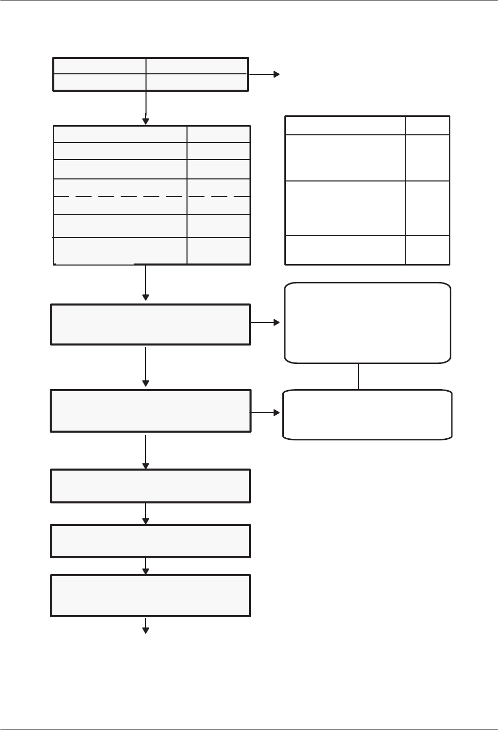
Figure 1-1 shows the order in which information is requested when using the INST
ALL program.
1-2
Installation and Maintenance
V
olume
Octel Overture 200/300 Serenade 3.0
PB60014–01
Manufacturer
Model
SP 3a
SP 3b
NETWORK
ROUTES
Route, Drop, Access
USER
MBX,EXT,COS or
MBX,COS (if mbx = ext)
Figure 1-1 Order of Questions and Associated T
ables in the INST
ALL Program
INSTALL Questions
For each manufacturer and model, specific
system parameters are supplied from the
Serenade database. These vary, depending upon
the telephone system and installation. A few
examples follow:
You must include all companyĆ
greeting mailboxes, intercept
mailboxes, distributionĆlist pilot
numbers, extended mailboxes (pilot and
members), flexible menu mailboxes,
and system users (mailboxes with
extensions and mailboxes only).
Enter the COS, even if you have not
assigned the correct attributes.
Attributes can be added or deleted in
the UPDATE program.
Installation name
NETWORK
LOCA
TION
Location Name, Protocol, Digital Networking
NETWORK
NUMBERING
Location Name, Access,
Additional Digits
System ID number
Alarm number
Cancel forward string
Forward string
Minimum
length for
security codes
Default mailbox
security code
b)
c)
e)
f)
g)
h)
SP 1 TRANSFER INIT
reconnect-RNA
reconnect-BUSY
transfer complete
ALTERNATE XFER
reconnect-RNA
reconnect-BUSY
transfer complete
PBX INIT CODE
1.
SP 2
SP 31
SP 45
SP 46
SP 144
SP 105
SP 9
SP 13
SP 16
SP 33
SLOTS
Card, Port, Ext, COS, Mode, Outcall, Test
FLASH TIME, ms.
a)
INSTALL
1-3
Octel Overture 200/300 Serenade 3.0
PB60014–01
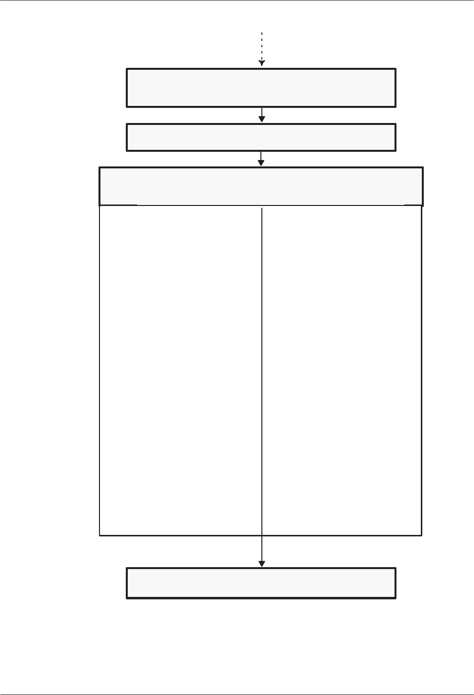
Figure 1-1 Order of Questions and Associated T
ables in the INSTALL Program (continued)
LIST
Distribution List number and members. All must previously have been
entered in the USER Table.
COS (Class of Service) Only changed during UPDATE.
SCHEDULE
TABLE
T
ime period 1...8 plus Default Days/Start T
ime/Stop T
ime
1Intercept Mailbox
2Company Greeting Mailbox
3Call Blocking Number
4Max Digit for Menu
5Prefix Digits for Menu
6Prefix Extension Number
7Rings Before No Answer
9Times to Retry on Busy
10 Use Alt Transfer Codes
18 Next Mailbox
26 AutoĆTransfer to Assistance
27 Message with AutoĆTransfer
29 Language
34 Logon Failure Transfer Mailbox
1Intercept Mailbox
3Call Blocking Number
4Max Digit for Menu
5Prefix Digits for Menu
6Prefix Extension Number
7Rings Before No Answer
8Msg Wait Rings
9Times to Retry on Busy
10 Use Alt Transfer Codes
11 Divert Msgs to Mailbox
12 Message Waiting Notification
13 Auto Greeting Activation
14 Offsite Attempt Times
15 Offsite Speak Times
16 Offsite Speak Delay
17 Offsite Prefix Digits
18 Next Mailbox
19 Offsite Dial System Parameter Digits
20 Offsite End System Parameter Digits
21 FIFO Queue Message Mailbox
22 Maximum Message Length
23 Maximum Number of Messages
24 Personal Assistance
25 Quick Greeting Activation
26 AutoĆTransfer to Assistance
27 Message with AutoĆTransfer
28 Announce Calls to Intercept
29 Language
30 Group Fax Number
31 Offsite Only if Urgent
32 Max Fax Delivery Attempts
33 Help Operator Mailbox
35 Override Trunk Group Number
36 Default Greeting Mailbox
INSTALL Questions (continued)
INFORMATION
TABLE
Different
questions are asked, depending on whether
the table applies to a
port or a mailbox.
1-4
Installation and Maintenance
V
olume
Octel Overture 200/300 Serenade 3.0
PB60014–01
1.2 USING
INST
ALL
The
customer
’
s specific configuration needs should be determined and a configuration package
completed before the installation begins. Use the configuration package to answer each question in
the INST
ALL program. A blank configuration package can be found at the end of the Understanding
Configuration chapter in the
Configuration
volume.
Follow the directions in the
Installation and Maintenance
volume, Installation chapter
, Connecting
T
erminals section, to connect your terminal to the Octel Overture
200/300 message server
.
Entering the INSTALL Program
Enter
the maintenance-level password to access the message-server database. If this is a new
installation and the password has not been changed, enter the maintenance-level password set by the
manufacturer.
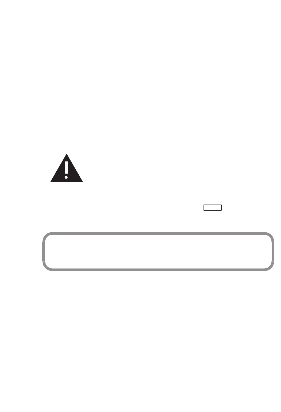
Caution!
Y
ou should change the manufacturer password to
ensure the security of the server
. Refer to the
Configuration
volume, Understanding Configuration
chapter
, Assuring Security section.
At the @ prompt, on the terminal, type
INSTA
or
INSTAL
and press
. The terminal displays
the following messages:
@INSTA
–––––––– SYSTEM INSTALLATION DIALOG ––––––––
DAY MM/DD/YYYY HH:MM:SS SYSTEMNAME ID:XXXXX S/N:XXXXXX PBX:00
INSTALL
then identifies the type of installation.
New installation.
INST
ALL question 1 follows.
Installation is in progress.
INST
ALL can continue, or it can start over
.
Message server has previously been installed.
T
o reinstall the message server
, you must enter the maintenance password to initiate the reinstall.
The r
einstallation begins by erasing all stor
ed information and messages. Do not use
r
einstall unless you ar
e pr
epar
ed to lose messages.

INSTALL
1-5
Octel Overture 200/300 Serenade 3.0
PB60014–01
Exiting the INSTALL Program
When
the program is completed, INST
ALL displays the following prompts:
WARNING: FOR PROPER OPERATION SYSTEM MUST BE RESTARTED AFTER INSTALL!
INSTALL COMPLETE.
WAIT... DONE.
SAVE configuration to a DISKETTE? ( Y/N , empty line = N ).
:
DAY MM/DD HH:MM:SS YYYY NAME ID: S/N: PBX:
–––––––– SYSTEM INSTALLATION COMPLETED ––––––––
Answer
Y
to copy all the data onto the configuration diskette as a backup. The Octel Overture
200/300 must be reloaded after the INST
ALL is complete.
T
o exit before you have completed the INST
ALL program, at the colon (:) type:
.E
When
you type (
.E
) to exit, the portion of the completed configuration is saved to the hard disk. Y
ou
can continue the INST
ALL later
, from where you left of
f, or you can start the INST
ALL over
. Refer
to the Starting INST
ALL Over section or the Exiting and Continuing section of this chapter
.
Modifying Tables While Using INSTALL
While
using the INST
ALL program, you can access the UPDA
TE program to list, add, modify
, or
delete information in the configuration tables.
The INST
ALL program displays a colon (:) when it is waiting for a response. At the colon, type a dot
(.
), which is the UPDA
TE prompt, then an
L
(list), an
A
(add), an
M
(modify), or a
D
(delete),
followed by the name of the table you want to alter
. For example,
:.A USER
The INST
ALL program activates the UPDA
TE program. Alter the tables as necessary
. T
o exit
UPDA
TE, press
at the colon. The INST
ALL program resumes.

1-6
Installation and Maintenance
V
olume
Octel Overture 200/300 Serenade 3.0
PB60014–01
+ Auto-Increment, USER Table Input Aid
When
entering a sequence of mailboxes into the USER Table, the auto-increment input aid allows
you to enter a
+
after the COS to automatically increment to the next sequential mailbox/extension
number
. If the extension field is N, only the mailbox number is incremented. The COS is not
changed. Auto-increment does not cross over to a new first digit. If it is attempted, the Octel
Overture 200/300 prompts
SORRY, (“+”) AUTO–INCREMENT CAN’T CROSS FIRSTDIGIT BOUNDARY.
For
example, to enter a sequence of mailbox numbers one by one, enter the mailbox, extension,
COS, and
+
. The next line displays the mailbox and COS, copied from the previous range, increasing
the number by one. T
o continue increasing, type a
+
after the COS. Press
to go to the next
mailbox. T
o stop incrementing the numbers, do not enter the
+
, just press
. The next line will
have no information in it, and the next mailbox may be entered.
The extension number does not need to match the mailbox number to use auto-increment. If mailbox
and extension numbers do not match, be sure the extension number is supposed to be incremented, as
well as the mailbox number
. If not, do not use auto-increment.
This example shows how to enter mailbox information using auto-increment. The bold characters are
what was entered.
:4500,4501,0+
:4501,4502,0+
:4502,4503,0
:4700,N,1
:4800,N,5
Adding Mailboxes in Ranges, USER Table Input Aid
To
add mailboxes in the USER Table in ranges, enter the first and last mailbox numbers, the first
extension number, and common COS. The mailbox and extension numbers are incremented by one,
and the COS remains the same for all entries.
This example shows how to enter mailbox information in ranges.
:4500–4599,4600,0
For this example, mailboxes 4500– 4599, with corresponding extension numbers 4600–4699, each
with COS
0,
are added to the USER T
able.
Mailbox and extension numbers
cannot
cross a first digit boundary. Auto-increment cannot be
used when adding in ranges.

INSTALL
1-7
Octel Overture 200/300 Serenade 3.0
PB60014–01
1.3 ANSWERING
QUESTIONS IN INST
ALL
During INST
ALL, refer to the customer
’
s completed configuration package. The configuration
package supplies you with the information you need to answer the questions.
After entering the INST
ALL program, if this is a new installation, the message server asks whether
the date and time should be set as shown. The INST
ALL questions follow
.
@INSTA
––––––– SYSTEM INSTALLATION DIALOG –––––––
DAY MM/DD/YYYY HH:MM:SS SYSTEMNAME ID:XXXXX S/N:XXXXXX PBX:00
NEW CONFIGURATION INSTALLATION.
Do you wish to set the system DATE and TIME? (Y/N, empty line = N)
:Y
Current DATE and TIME:
DAY MM/DD/YYYY HH:MM
Enter new DATE and TIME as: DAY MM/DD/YY HH:MM
or empty line for no change.
MOD:DAY MM/DD/YYYY HH:MM
DATE and TIME set to:
MON MM/DD/YYYY HH:MM
Is this correct? (Y/N, empty line = N):Y
All Messages older than this Date will be deleted.
Are you sure: (Y/N, empty line = N):
1.
SYSTEM P
ARAMETERS
Question
1 is a series of questions that modify specific system parameters; the information entered is
automatically transferred into the SYSTEM PARAMETER T
able.
Question 1. a) displays a list of telephone manufactur
ers fr
om which to select.
Enter the number corresponding to the manufacturer
’
s name, and press
. After you have
selected the telephone manufacturer
’
s number
, the model numbers for that manufacturer are listed.
Select the appropriate number for that model telephone system.
1. SYSTEM PARAMETERS.
a) Select the MANUFACTURER–NUMBER of your telephone system
from the following list.
0 – OTHER 1 – ITT
2 – TIE
.
.
:X
Select the MODEL–NUMBER of your telephone system
from the following list.
0 – OTHER
.
.
.

1-8
Installation and Maintenance
V
olume
Octel Overture 200/300 Serenade 3.0
PB60014–01
If
the telephone manufacturer is not listed, enter
0
for Other and press
. If 0
for Other
is selected, specific questions about the other telephone system are asked, before continuing
with question 1.b). Refer to the Answering Questions About Other T
elephone Systems section
in this chapter, for an explanation of these questions.
After the telephone system model number has been selected, the next questions ask whether the
DTMFINT and T
ONEDET T
ables should be reset. These questions are displayed even if the PBX
selected does not require the DTMFINT or T
ONEDET T
ables. For both DTMFINT and T
ONEDET
T
ables, the default or empty line is YES. Therefore, if you are installing a server
that does not
require
the DTMFINT or T
ONEDET T
able, enter
N.
Do you wish to RESET DTMFINT TABLE to FACTORY–DEFAULTS for
this PBX? (If ”YES” , ALL current values will be LOST!)
( Y/N, empty line = Y ):
LOADING CONFIGURATION DATA...DONE
Do you wish to RESET TONEDET TABLE to FACTORY–DEFAULTS for
this PBX? (If “YES” , ALL current values will be LOST!)
( Y/N, empty line = Y ):
Question
1. b) asks for the company name.
b) What is the name of the company at which this system
is being installed? (1–8 characters).
:
This
name is used for internal reports. Up to eight characters can be entered; use the entire name or
an abbreviation of the name.
Question 1. c) asks for the system ID number
.
c) What is the SYSTEM ID number? (1–6 digits).
:
The
serial number of the message server can be used as the system ID number
. The serial number is
printed on the message server/UL label located at the lower rear of the cabinet. It is important that a
dif
ferent number be used for each Octel Overture 200/300. This number is used to distinguish among
Octel Overture 200/300 message servers and to identify the message server when an alarm call is
made.
Question 1. e) asks for the telephone number of the person who should r
eceive alarm calls.
e) What extension or phone number should be called when an ALARM
is encountered? (If this is an outside call, precede it with
the EXTERNAL ACCESS CODE and an Expect–Dial–Tone, where necessary.)
( 1–20 chars. May include: 0–9,*,#, D=DELAY, E=EXPECT–DIAL–TONE
empty Line = NONE )

INSTALL
1-9
Octel Overture 200/300 Serenade 3.0
PB60014–01
If
something goes wrong with the message server
, it can call and report the problem. This can be an
on- or of
f-premise number
. Include access codes, if necessary
. Enter a
D
for a delay after any access
codes you might use. (The length of the delay is determined by System Parameter 28.) Enter an
E for
“expect dial tone.”
Do not
use any spaces.
Question 1. f) asks for the string of numbers to be dialed for the forwarding string and the
cancel-forwarding string when the message server is r
eloading or finished r
eloading.
f) What is the forwarding string, including destination extension,
to be dialed when the system is reloading and cannot accept calls?
(May include: 0–9,*,#, D=DELAY, E=EXPECT DIAL TONE, or F=FLASH,
1–12 chars, empty line = NONE )
:
What is the cancel–forwarding string, to be dialed when the system
has finished reloading and is ready to accept calls?
(May include: 0–9,*,#, D=DELAY, E=EXPECT DIAL TONE, or F=FLASH,
1–12 chars, empty line = NONE )
:
While
the Octel Overture 200/300 is reloading after a power failure, the ports can be forwarded to an
alternate answering point. Enter the code that causes incoming calls to ring at the alternate answering
location. If
NONE
is entered, all ports remain of
f hook (busy) when the message server is loading or
reloading.
The second part of this question asks for the cancel-forwarding number to be entered, which allows a
return to the Octel Overture 200/300 when the server is again operational.
Question 1. g) asks for the minimum length for all mailbox security codes.
g) Enter the minimum length for all security codes.
(0–10, empty line = 0 )
:
The
answer to this question defines the value for System Parameter 144 — MINIMUM LENGTH
FOR SECURITY CODES. The maximum length for a security code is 10 digits.
If this is changed after the initial installation, existing security codes with fewer digits are not
af
fected until the mailbox holder changes the security code.
Question 1. h) asks for the default security code for mailboxes
that logon using a mailbox
number.
h) For mailboxes which logon via MAILBOX number (NO port/trunk cos attr 106)
enter the DEFAULT SECURITY CODE.
Note: This code will apply to all mailboxes which do not have a security
code defined.
(xx –10 digits, empty line = NONE )
:

1-10
Installation and Maintenance
V
olume
Octel Overture 200/300 Serenade 3.0
PB60014–01
If
question 1. g) is configured, all new mailboxes must have a security code of the minimum length
or longer
. The security code entered is the value defined for System Parameter 105 — DEF
AULT
SECURITY CODE FOR MAILBOXES. This security code remains on each mailbox until a user
logs on to the mailbox and changes it.
The User ID Logon is not configured in the INST
ALL program. Refer to the
Feature
Description
volume, Customizing System-W
ide Features chapter
, Mailbox Logon section.
XX
is the value defined in question 1. g) for System Parameter 144. A default security code
must be set if the minimum length is greater than zero.
The security code assigned through this INSTALL question can be changed or deleted through
System Parameter 105. If the value of this parameter is modified, any existing mailboxes that already
have the default security code are automatically assigned the new default security code.
2.
USER
2. USER.
Enter each user’s MAILBOX, EXTENSION, and COS. Enter as:
(Mailbox=1–8 digits, Name=1–20 characters)
Extension=1–8 digits, COS=0–254, Enter NONE if desired for EXTENSION.
Enter “+” after COS to automatically increment:
MAILBOX, and EXTENSION.
Also, enter any mailboxes to be used as DISTRIBUTION LISTS.
To add users in a range, enter as:
MAILBOX1–MAILBOX2,EXTENSION,COS.
Enter empty line when done.
:2001–2019,2001,10
NOTE: MAILBOXES with first digit ”2” are 4 digits long.
:
Do you wish to add more users? (Y/N, empty line = Y)
:N
For
each user
, enter a mailbox number
, extension number, and COS, separated only by commas. If
System Parameter 212 — USER I.D. LENGTH, is configured, enter the user ID number after the
mailbox number
. Do not enter any spaces. Press
after each line. Enter the numbers carefully
to avoid errors. Y
ou can correct mistakes later by using the
MODIFY
command in the UPDA
TE
program.
Define every mailbox, including individual mailboxes, information-only mailboxes, greeting
mailboxes, and distribution-list pilot numbers. Make sure to enter intercept mailboxes (numbers sent
when a caller does nothing or presses
for assistance.)
In the INST
ALL program, you can define users without the COS being created first in
UPDATE.
When adding multiple users that have the same COS, you can add them in a range. Refer to the
Adding Mailboxes in Ranges, USER T
able Input Aid section in this chapter
. Y
ou cannot cross
mailbox or extension first-digit boundaries when adding users in a range.
When adding a sequence of mailbox numbers one by one, you can enter a + after the COS to
automatically increment to the next sequential mailbox number
. Refer to the + Auto-Increment,
USER T
able Input Aid section in this chapter
.

INSTALL
1-1
1
Octel Overture 200/300 Serenade 3.0
PB60014–01
After
each mailbox is entered, a colon (:) is displayed, indicating that the next mailbox can be
entered.
Press
at the colon when you are finished entering mailboxes. The message server prompts
Do you wish to add more users?
Enter
N.
The INST
ALL program goes to the next
question.
If you press
before finishing, the Octel Overture 200/300 asks whether you want to exit the
USER T
able. Simply respond NO to return to the USER T
able. Mailboxes may also be added later
using UPDA
TE.
3.
SLOTS
The SLOTS T
able contains information about each line card slot, integration card slot, and
applications card slot. The SLOTS T
able allows each line card and integration card to be configured
individually
. Enter the slot number and the type of card to be installed.
.3. SLOTS
Enter SLOT NUMBER to INSTALL
INS:1
6 –LIC4 2 –SLIC 8 –ACP
7 –DAC4 3 –RIC 17–FAX4
10–LIC8 4 –ATTIC 16–FAX8
11–TLC8 13–SIC8 22–LAN
18–LIC4I
5 –MITEL
23–DTC17–E1
26–DLC16
50–PICROLM
51–PICATT
52–PICNT
33–ILIC12FR
34–ILIC12UK
35–ILIC12JP
37–ILIC12GR
Enter Card Type.
SLOT 1 : 6
When
the configuration information for a port is the same information entered for the previous
port, only the extension number of the port need be entered, followed by
. The
information for the remainder of the line is automatically entered.
Dif
ferent cards can be configured within a single Octel Overture 200/300. The EntryW
orks
ACP card
can only be configured in slot 7 for the Octel Overture 200 and in slot 12 for the Octel Overture 300.
The dialog for configuring a telemarketing line card (TLC) is similar to the dialog for
configuring a line interface card (LIC).
After you enter the card type for DLC16, ILC12, and PIC, enter the LSTT
AB T
able to be referenced.

1-12
Installation and Maintenance
V
olume
Octel Overture 200/300 Serenade 3.0
PB60014–01
.SLOT 1:51
Enter LSPTAB table to be referenced for this slot.
0–DEFAULT
1–ILC12_FR.
2–ILC12_GE
3–DLC16_US
4–DLC16_AU
5–DLC16_GE
6–ILC12_US
7–DLC16_FR
8–TI
9–MD110-E1
10–DLC16_UK
11–ILC12_UK
12–DLC16_90
(Empty line = 0)
MOD:
Should this card be:
(1 – PRIMARY
2 – SECONDARY
3 – TERTIARY
N – no ) sync receiver of the master clock?
(1–3, N. Empty line = N):
When
you install a PIC card, you must configure the system-clock (master clock) sync source. Refer
to the
Configuration
volume, Slots T
able chapter
, for information about the LSPT
AB T
able and the
master clock configuration.
The following examples show the dialog for configuring the dif
ferent cards. Refer to the
Configuration
volume, Slots T
able chapter
, Using UPDA
TE section, for information about
configuring the card types.
Direct Access Card (DAC)
SLOT 2:7
Enter information for each PORT.
Enter as: EXTENSION NUMBER connected to each port (1–8 digits),
CLASS–OF–SERVICE (0–254), SIGNALLING (DTMF, Rotary),
TRUNK TYPE (Wink, Immed, Delay, Loop, Ground).
1 :333,254,DTMF,DELAY

INSTALL
1-13
Octel Overture 200/300 Serenade 3.0
PB60014–01
Integration
Card
SLOT 4 :5
Enter information for each PORT.
Enter as: EXTENSION NUMBER connected to each port (1–8 digits),
CLASS–OF–SERVICE (0–254), ANSWER MODE (AX, CX, MX), USE PORT FOR
MESSAGE WAITING AND NETWORK OUTCALLING (Y/N), TEST CHANNEL (Y/N)
1 :334,250,AX,N,N
2 :
Configure Integration (1–4=Msg Waiting Link):1
Enter empty line when done.
INS:
Integration
cards installed in the message server must be the same. Integration cards can be installed
in Slots A1 through A6 for the Octel Overture 200. For the Octel Overture 300, most integration
cards can be configured in any slot not used for line cards. A
TTIC integration cards and SIC8 cards
cannot go in slot 12 of the Octel Overture 300.
Except for the A
T&T System 75/Definity G1, and the G3 ATTIC integrations, each port can be
allocated to only one integration unit. Refer to the
Integration
volume for additional details about the
specific integration you are configuring.
The fax application processor card can be installed in any unoccupied slot in the Octel Overture
200/300 cabinet. The following is an example of the dialog for configuring a fax application
processor.
.SLOT 8:17
Enter information for each PORT.
Enter as: CLASS-OF-SERVICE ( 0–254 ), TEST CHANNEL (Y/N).
1:126,N
2:126,N
4.
NETWORK ROUTES
5. NETWORK LOCA
TIONS
6. NET NUMBERING PLAN
Questions
4, 5, and 6 pertain to collocated message servers and multilocation networking.
For information about configuring networking, refer to the
Networking
volume.

1-14
Installation and Maintenance
V
olume
Octel Overture 200/300 Serenade 3.0
PB60014–01
4. NETWORK ROUTES.
Enter the name for each NETWORK ROUTE, whether the route can be
dropped upon reconnect to caller, and the ACCESS DIGITS to be dialed.
ENTER AS:
ROUTE NAME (1–6 chars), DROP (Y or N), ACCESSDIG (1–29 digits)
ACCESS DIGITS may include: 0–9,*,# or any of the following:
D – delay.
E – wait for DIAL TONE here.
N – wait for DIAL–UP OCC DIAL TONE here.
P – dial PUBLIC NETWORK NUMBER here.
T – dial TIE NETWORK NUMBER here.
Enter empty line when done.
:33,N,456
:
5. NETWORK LOCATIONS.
Enter requested information for all NETWORK LOCATIONS.
Enter new LOCATION NAME. (1–6 chars) Enter empty line when done.
:(location name)
Does (location name) have a SYSTEM? (Y/N, empty line = Y)
:
Press
after each question to continue.
If you are installing a single-cabinet message server without remote networking, press
to skip to question 7. DISTRIBUTION LISTS.
If the (location name)
does not have
a SYSTEM, the next question is as follows:
Does (location name) have the same PBX type as SELF? (PBX type)
(Y/N, empty line = N) (If ”YES”, will do CALL–PROGRESS–DETECTION.)
:
If
the (location name)
does have
a SYSTEM, enter the protocol to use, as follows:
Enter the PROTOCOL to use with (location name) (1,2,3,4,5,empty line =3)
If
the above question is answered with
2
, refer to the
Networking
volume,
Analog
Networking
chapter and Location T
able chapter
.
If the above question is answered with 4 for AMIS Analog
networking,
refer to the
Networking
volume,
Analog
Networking chapter and Location T
able chapter
.
If the above question is answered with
5
, refer to the
Networking
volume,
Analog
Networking
chapter and Location T
able chapter
.

INSTALL
1-15
Octel Overture 200/300 Serenade 3.0
PB60014–01
Is (location name) located on the same PBX as this system? (Y/N,empty line = N)
:
Enter ROUTE NAMES for up to three ROUTE CHOICES to (location name) .
1:
2:
3:
Enter PUBLIC NETWORK NUMBER (PNN) to call (location name) .
(May include: 0–9,*,#, D=DELAY, E=EXPECT DIAL TONE, or Cn.
1–12 chars, empty line = NONE )
:
Enter TIE NETWORK NUMBER (TNN) to call (location name) .
(May include: 0–9,*,#, D=DELAY, E=EXPECT DIAL TONE, or Cn.
1–7 chars, empty line = NONE )
:
Is (location name) accessible over the DIGITAL NETWORK? (Y/N, empty line = N)
:
If
the above question is answered
Y
for Digital Networking, refer to the
Networking
volume, Digital
Networking chapter
.
6. NET NUMBERING PLAN.
Enter NUMBERING PLAN information for each NETWORK LOCATION.
Enter as:
LOCATION NAME, INITIAL DIGITS (1–8 digits), NET MAILBOX LENGTH (1–16),
NUM OF DIGITS TO STRIP(0–15)., NUM OF DIGITS TO STRIP FROM SELF(0–8)
Enter empty line when done.
7.
LISTS
Question
7 is used to create System Distribution Lists.

1-16
Installation and Maintenance
V
olume
Octel Overture 200/300 Serenade 3.0
PB60014–01
7. DISTRIBUTION LISTS.
Enter the LIST NUMBER. (1–16 digits).
This Number must already exist as a mailbox in the USER table.
Then enter each mailbox to be added to the list.(1–16 digits).
If the list exists, new mailboxes will be appended to existing ones.
Enter empty line when done.
Enter DISTRIBUTION LIST NUMBER.
ADD:4000
WARNING: MESSAGES IF ANY IN MAILBOX WILL BE LOST!
ARE YOU SURE (Y/N) ? (Y/N, EMPTY LINE = N):Y
NEW DISTRIBUTION LIST.
Enter each MAILBOX or RANGE to be added to this list.
During INST
ALL, you can create system distribution lists and add member addresses. The
distribution list number and member numbers must already exist as a mailbox in the USER T
able.
If distribution lists are not being added during INST
ALL, press
. Y
ou can add them later
,
through the UPDA
TE program.
8.
COS
COS
tables are not configured during the INST
ALL program. When INST
ALL is complete, enter the
UPDA
TE program and add attributes to the COS numbers that were defined for each port and
mailbox defined in the USER T
able in question 2. Refer to the
Configuration
volume, COS chapter
.
8. COS.
UPDATE if necessary when INSTALL is complete.
9.
INFORMA
TION T
ABLES
Question
9 lists the INFORMA
TION T
able indexes for either port or mailbox configuration.
9. INFORMATION TABLES.
Enter the INFORMATION TABLE number to be added. (1–255)
Enter empty line when done.
:254
Is TABLE 254 for a PORT/TRUNK? (If NO, it’s for a MAILBOX.)
(Y/N, empty line = N)
:Y
To COPY an existing INFORMATION TABLE, enter the TABLE NUMBER.
(1–255, empty line = NONE)
Define
at least one port and one mailbox INFORMA
TION T
able, because a default INFORMA
TION
T
able
must be
entered for every SCHEDULE T
able (Question 10).

INSTALL
1-17
Octel Overture 200/300 Serenade 3.0
PB60014–01
The
Octel Overture 200/300 obtains data from the INFORMA
TION T
ables to determine how each
port and mailbox process the calls. The COS for each port and mailbox points the Octel Overture
200/300 to the SCHEDULE T
able to determine which INFORMA
TION T
able to use.
When adding an INFORMA
TION T
able, be sure to answer the first question accurately —
IS
TABLE X FOR A PORT/TRUNK? (If NO, it’s for a Mailbox.) This
is important
because the subsequent questions are dif
ferent for ports/trunks and mailboxes. For consistency and
clarity
, number port INFORMA
TION T
ables from 255, descending, and mailbox INFORMA
TION
T
ables from 1, ascending.
Port
INFORMA
TION T
able Indexes
The
following indexes are applicable to port INFORMA
TION T
ables. Refer to the
Configuration
volume, Information T
able chapter, for details about each index.
Index 1.
Each port/trunk INFORMA
TION T
able must have an intercept position. The mailbox
must already exist in the USER T
able.
1. INTERCEPT MAILBOX
(1–8 digits )
:
Index
2.
A company greeting mailbox can be configured. If a mailbox number is not entered,
the manufacturer
’
s recorded generic greeting is used.
2. COMPANY GREETING MAILBOX (1–8 digits, N = NONE, empty line = NONE )
:
Index
3. The following index appears if the Incoming Call Restriction option is installed.
3. CALL BLOCKING NUMBER (0–255, 0 = NONE, empty line = NONE)
:
Indexes
4 and 5.
The following indexes appear if the Single Digit Menus option is installed.
Index 5 is not listed if index 4 is NONE.
4. MAX DIGIT FOR MENU (0–8, 0 = NONE, empty line = NONE)
:
5. PREFIX DIGIT FOR MENU (1–7 DIGITS, N = NONE, empty line = NONE)
:XX
WARNING: The following MAILBOXES must exist in the USER TABLE or in a
COLOCATED cabinet:

1-18
Installation and Maintenance
V
olume
Octel Overture 200/300 Serenade 3.0
PB60014–01
Indexes
6, 7, 9, 10, and 18.
The following five indexes are listed.
6. PRE EXTENSION DIGITS
(1–12 digits; may include: 0–9, *, #, D=DELAY, E= EXPECT–DIAL–TONE,
N = NONE, empty line = NONE )
(When caller dials EXTENSION that is not a defined MAILBOX.)
:
7. RINGS BEFORE NO ANSWER (3–20, empty line = 4 )
(When caller dials EXTENSION that is not a defined MAILBOX.)
:
9. TIMES TO RETRY ON BUSY (0–40, empty line = NONE)
(When caller dials EXTENSION that is not a defined MAILBOX.)
:
10. USE ALT TRANSFER CODES (Y/N, empty line = N)
(When caller dials EXTENSION that is not a defined MAILBOX.)
:
18. NEXT MAILBOX (1–8 digits, N = NONE, empty line = NONE )
:
Indexes
26 and 27.
The following indexes are used with Personal Assistance, Adaptive Integration,
and with the DID/E&M T
runk Interface Module. Index 27 is not listed if index 26 is
N.
26. AUTOTRANSFER TO ASSIST (Y/N, empty line = N)
:
27. MSG WITH AUTO TRANSFER (Y/N, empty line = N)
:
Index
29. The following index appears if the Multilingual Prompts option is installed. The
languages shown in index 29 depend on current settings. The following is an example where
English and Spanish are currently installed.
29. LANGUAGE: 0= NONE
1= ENGL US––V VERSION 8D
2= SPANISH VERSION 8D
(0–2, empty line = 0)
Index
34.
When index 34 is configured, callers are transferred to assistance instead of being
disconnected if their attempts to log on are unsuccessful.
34. LOGON FAILURE XFER MAILBOX (1–8 digits, N = NONE, empty line = NONE )
:

INSTALL
1-19
Octel Overture 200/300 Serenade 3.0
PB60014–01
After
index 34 is answered, the port INFORMA
TION T
able is complete, as shown.
––– INFORMATION TABLE 254 COMPLETE –––
Enter the INFORMATION TABLE number to be added. (1–255)
Enter empty line when done.
Mailbox
INFORMA
TION T
able Indexes
The
following indexes are applicable to the mailbox INFORMA
TION T
able. Refer to the
Configuration
volume, Information T
able chapter, for details about each index.
Index 1.
If an intercept mailbox is not defined for a mailbox, the call defaults to the Intercept
Mailbox defined for the port or trunk on which the call came in.
1. INTERCEPT MAILBOX If none, uses PORT/TRUNK info.
(1–8 digits, N = NONE, empty line = NONE )
:
Index
3. The following index appears if the Incoming Call Restriction option is installed.
3. CALL BLOCKING NUMBER (0–255, 0 = NONE, empty line = NONE)
:
Indexes
4 and 5.
The following indexes appear if the Single Digit Menus option is installed.
Index 5 is not listed if index 4 is NONE.
4. MAX DIGIT FOR MENU (0–8, 0 = NONE, empty line = NONE)
:
5. PREFIX DIGIT FOR MENU (1–7 DIGITS, N = NONE, empty line = NONE)
:XX
WARNING: The following MAILBOXES must exist in the USER Table:

1-20
Installation and Maintenance
V
olume
Octel Overture 200/300 Serenade 3.0
PB60014–01
Indexes
6 thr
ough 13.
The following indexes are listed.
6. PRE EXTENSION DIGITS
(1–12 digits; may include: 0–9, *, #, D=DELAY, E= EXPECT–DIAL–TONE,
N = NONE, empty line = NONE )
:
7. RINGS BEFORE NO ANSWER (3–20, empty line = 4 )
:
8. MSG WAITING RINGS (3–20, empty line = 4 )
:
9. TIMES TO RETRY ON BUSY (0–40, empty line = NONE)
:
10. USE ALT TRANSFER CODE (Y/N, empty line = N)
:
11. DIVERT MSG TO MAILBOX (1–8 digits, N = NONE, empty line = NONE )
:
12. MSG WAITING NOTIF (Y/N, empty line = Y)
:
13. AUTO GREETING ACTIVATION (Y/N, empty line = N)
:
Index
14. The following index is only listed if index 12 is
Y.
14. OFFSITE ATTEMPT TIMES (0–255, empty line = NONE)
:
Indexes
15, 16, and 17.
The following indexes are not listed if index 14 is
0.
15. OFFSITE SPEAK TIMES (0–8, empty line = 3)
:
16. OFFSITE SPEAK DELAY (1–32 seconds, empty line = 5)
:
17. OFFSITE PREFIX DIGITS
(1–12 digits; may include: 0–9,*,#, D=DELAY, E=EXPECT–DIAL–TONE,
N=NONE, empty line=NONE)
:
Index
18. The following index is listed.
18. NEXT MAILBOX (1–8 digits, N = NONE, empty line = NONE )
:

INSTALL
1-21
Octel Overture 200/300 Serenade 3.0
PB60014–01
Indexes
19 and 20.
If the answer to index 18 is
0
, indexes 19 and 20 are not listed. When index
20 is yes, the digit string to be dialed must be configured in System Parameter 259.
19. OFFSITE DIAL SYSP DIGS (Y/N, empty line = N)
:
20. OFFSITE END SYSP DIGS (Y/N, empty line = N)
:
Index
21.
The following index appears if Call Queuing is installed.
21. FIFO QUEUE MSG MAILBOX (1–8 digits, N = NONE, empty line = NONE)
:
22. MAXIMUM MSG LENGTH (1–180 minutes, empty line = 6 minutes)
:
23. MAX NUMBER OF MSGS (1–60, empty line = 32 )
:
24. PERSONAL ASSISTANCE (Y/N, empty line = N)
:
Index
25. The following index appears if Adaptive Integration is installed.
25. QUICK GREETING ACTIV (Y/N, empty line = N)
:
26. AUTOTRANSFER TO ASSIST (Y/N, empty line = N)
:
27. MSG WITH AUTO TRANSFER (Y/N, empty line = N)
:
28. ANNOUNCE CALLS TO INT (Y/N, empty line = N)
:
Index
29.
This index appears if Multilingual Prompts is installed. The languages shown in
Question 29 depend on current settings. The following is an example where English and Spanish
are currently installed.
29. LANGUAGE: 0= NONE
1= ENGL US––V VERSION 8D
2= SPANISH VERSION 8D
(0–2, empty line = 0)

1-22
Installation and Maintenance
V
olume
Octel Overture 200/300 Serenade 3.0
PB60014–01
Indexes
30 and 32.
These indexes appear if Fax Mail Plus is installed. For index 30, enter the
digits of the telephone number for the designated group fax delivery machine.
30.GROUP FAX NUMBER
(1–32 digits, may include: 0–9, *, #, D=DELAY, E=EXPECT-DIAL-TONE,
empty line = NONE )
ADD:
Index
31.
Enter YES in the following item to provide for of
fsite/pager outcalling to be made
only for ur
gent messages. The default is NO.
31. OFFSITE ONLY IF URGENT (Y/N, empty line N)
ADD:
32. MAX FAX DELIV ATTEMPTS
(0–255, 0=USE SYSTEM PARAMETER 209,
255=UNLIMITED,
empty line=SYSP 209)
ADD:
Indexes
33, 35, and 36. Index 33 is operational only if the 5000 User Interface feature is
installed.
33. HELP OPERATOR MAILBOX (1–8 digits, N = NONE, empty line = NONE )
:
35. OVERRIDE TRUNK GROUP NUMBER (1–8 digits, N = NONE, empty line = NONE)
:
36. DEFAULT GREETING MAILBOX (1–8 digits, N = NONE, empty line = NONE)
:
After
index 36 is answered, the mailbox INFORMA
TION T
able is complete, as shown.
––– INFORMATION TABLE 1 COMPLETE –––
Enter the INFORMATION TABLE number to be added. (1–255)
Enter empty line when done.
10.
SCHEDULE T
ABLES
Enter
a SCHEDULE T
able for each COS entered for the user mailboxes defined in Question 2.
The message server automatically requests a schedule for each COS number entered. Enter the
appropriate times, days, and INFORMA
TION T
able numbers for each SCHEDULE T
able time
period displayed. When finished with the time periods, enter an INFORMA
TION T
able to be used
for the default times.

INSTALL
1-23
Octel Overture 200/300 Serenade 3.0
PB60014–01
10. SCHEDULE TABLE.
– – – SCHEDULE FOR COS 10 – – –
TIME PERIOD 1:
Enter INFORMATION TABLE number to use. (1–255)
Enter empty line when done.
:
Enter applicable WEEKDAYS as: SU,MO,TU,WE,TH,FR,SA,HOL
(Empty line = MO,TU,WE,TH,FR)
:
Enter START time as: HOURS (00–23): MINUTES (00–59)
(Empty line = 00:00)
:
Enter STOP time as: HOURS (00–23): MINUTES (00–59)
(Empty line = 23:59)
:
TIME PERIOD 2:
Enter INFORMATION TABLE number to use. (1–255)
Enter empty line when done.
:
When
you are finished entering all time periods for the SCHEDULE T
able, press
at the
colon. The message server prompts for the default INFORMA
TION T
able number
.
Enter the DEFAULT INFORMATION TABLE number to use outside the
TIME PERIODS specified for COS 10 . (1–255)
INSTALL COMPLETE.
WAIT... DONE.
SAVE configuration to a DISKETTE? ( Y/N , empty line = N ).
:
WARNING: FOR PROPER OPERATION SYSTEM MUST BE RESTARTED AFTER INSTALL!
DAY MM/DD/YYYY HH:MM:SS SYSTEMNAME ID:XXXXXX S/N:XXXXXX PBX:00
–––––––– SYSTEM INSTALLATION COMPLETED ––––––––
@
Save
the configuration on your backup configuration diskette. Leave the diskette in the disk drive.
The Octel Overture 200/300 must be reloaded for to operate correctly
. T
o reload the Octel Overture
200/300, at the @ prompt, enter
RESTA 2
After
the message server has reloaded, it is recommended that you enter the UPDA
TE program and
use the
LIST
command to review the answers you just entered. Y
ou might also need to change some
of the system parameter values. Refer to the
Configuration
volume, System Parameter T
able chapter
,
in this volume.
Use the UPDA
TE program to modify system parameters and to set COS Attributes.

1-24
Installation and Maintenance
V
olume
Octel Overture 200/300 Serenade 3.0
PB60014–01
1.4 ANSWERING
QUESTIONS ABOUT OTHER TELEPHONE
SYSTEMS
The INST
ALL program asks the following questions when your telephone system manufacturer or
PBX model number is not listed in question 1.a).
Please answer the following questions for your telephone system:
How do you TRANSFER a call to another EXTENSION?
(May include: 0–9,*,#, D=DELAY, E=EXPECT DIAL TONE, or F=FLASH,
1–8 chars, empty line = NONE)
:FE
Enter
the sequence of events when transferring a call before you enter the destination extension
number
. For example, if the sequence is “flash,” wait for a dial tone, then enter the extension
number
, type
FE
. (If the telephone hookswitch is pressed momentarily
, that is considered a flash.)
Enter the sequence of events for a reconnection to the original caller
.
How do you RE–CONNECT to the caller if the EXTENSION doesn’t answer?
(May include: 0–9,*,#, D=DELAY, E=EXPECT DIAL TONE, or F=FLASH,
1–8 chars, empty line = NONE)
:F
This
is usually similar to transferring a call. For example, if
FE
is entered for a transfer
, an
F
(flash)
is probably used for a reconnection.
T
ype the digits, if any
, required to complete a transfer
. If there are none, press
.
What digits, if any, are dialed before HANG–UP to COMPLETE a transfer?
(May include: 0–9,*,#, D=DELAY, E=EXPECT DIAL TONE, or F=FLASH,
1–8 chars, empty line = NONE)
:
A
ringback is the sound you hear in the receiver when the telephone you are calling is ringing. The
standard ringback is one ring, alternating with silence. A double-interrupted ringback is two short
rings, and then silence. Enter
Y
for double ringback.
Does this telephone system give DOUBLE–INTERRUPTED RINGBACK
(Y/N, Empty line =N)
:Y

INSTALL
1-25
Octel Overture 200/300 Serenade 3.0
PB60014–01
Some PBX systems may require a digit sequence to be dialed so that system
extensions get assigned to the incoming call group.
What digits, if any, should be dialed on all PORTS upon POWER–UP?
(May include: 0–9,*,#, D=DELAY, E=EXPECT DIAL TONE, or F=FLASH,
1–8 chars, Empty line = E)
:
End of telephone system specific questions.
At
this point, the INST
ALL program continues with question 1.b), Company Name. Refer to the
Answering Questions in INST
ALL section.

1-26
Installation and Maintenance
V
olume
Octel Overture 200/300 Serenade 3.0
PB60014–01
1.5 EXITING
BEFORE THE INST
ALL IS COMPLETE
There
are two ways that you can leave and reaccess the INST
ALL program, shown in the following
examples. The first example shows what to do if you make a mistake during INST
ALL and, instead
of correcting it, you choose to exit and start over
. The second example shows what to do if you are
interrupted during INST
ALL and choose to stop temporarily and continue later
.
Restarting INSTALL
If
you make a serious mistake, and you don’
t want to fix it later
, you can leave the program and start
over
. At the point you wish to exit the program, type
.E
at the colon (:) prompt. The following
example, starting at question 1.c), shows how
.
c) What is the SYSTEM ID number? (1–6 digits).
:555
d) How many (Overture 200/300) ports will be used? (1–8, empty line = 4)
:.E
EXITING INSTALL
WAIT...DONE.
–––––––––––––––SYSTEM INSTALLATION SUSPENDED––––––––––––––
@
When
you want to return to the INST
ALL program, type
INSTA at
the @ prompt, as shown:
@INSTA
–––––SYSTEM INSTALLATION DIALOG
MON MM/DD HH:MM:SS YYYY SYSTEM NAME ID:000
You have an installation already in progress.
Do you wish to start over with a NEW INSTALLATION?
(Y/N, empty line = NO, continue installation in progress)
:Y
CLEARING ALL TABLES...DONE.
INITIALIZING ALL USER DIRECTORIES...DONE.
1.SYSTEM PARAMETERS.
a)Select the MANUFACTURER NUMBER ..... etc.
All
the information entered earlier has been cleared. Begin again with the first question. Refer to the
Answering Questions in INST
ALL section.

INSTALL
1-27
Octel Overture 200/300 Serenade 3.0
PB60014–01
Exiting and Continuing
If
you start INST
ALL and are interrupted, you can leave the program and continue later at the point
where you left of
f. The following example, starting at question 1.c), shows how
.
c) What is the SYSTEM ID number? (1–6 digits).
:555
d) How many (Overture 200/300) ports will be used? (1–8, empty line = 4)
:.E
EXITING INSTALL
WAIT...DONE
–––––––––––––––SYSTEM INSTALLATION SUSPENDED–––––––––––––
@
Later,
when you want to continue, type
INSTA
at the @ prompt, as shown.
@INSTA
–––––SYSTEM CONFIGURATION DIALOG–––––
DAY MM/DD HH:MM:SS YYYY SYSTEM NAME ID:000
You have an installation already in progress.
Do you wish to start over with a NEW INSTALLATION?
(Y/N, Empty line = NO, continue installation in progress)
d)How many ports will be used? (1–8, empty line = 4)
:
Begin
entering data where you left of
f.
Reinstalling
an Installed Octel Overture 200/300
After
the Octel Overture 200/300 is installed, situations could arise that warrant a reinstallation of
the message server such as the following:
The PBX has been replaced.
There were errors during INST
ALL. (Instituting a reinstallation might be more time-ef
ficient
than correcting major errors.)
The server has been upgraded to a lar
ger disk.
During a reinstallation, you can use the following options to:
Reinstall the Octel Overture 200/300, answering every question in the INST
ALL program.
Preload all the configuration tables from the backup configuration diskette.
Preload the specific range of tables.

1-28
Installation and Maintenance
V
olume
Octel Overture 200/300 Serenade 3.0
PB60014–01
Enter
INSTA
at the @ prompt. If you enter
Y
to reinstall the message server
, the message server
prompts for a password. Enter the maintenance level password. If you do not enter a password or you
enter an incorrect password, the INST
ALL program is aborted.
@INSTA
––––––– SYSTEM INSTALLATION DIALOG –––––––
DAY MM/DD HH:MM:SS YYYY SYSTEM NAME ID:000 S/N:000000 PBX:00
SYSTEM HAS ALREADY BEEN INSTALLED.
Do you wish to RE–INSTALL? (Y/N, empty line = N)
<<IF YES, ALL TABLES WILL BE CLEARED AND USER MESSAGES WILL BE LOST>>
:Y
PASSWORD:
CLEARING ALL TABLES...DONE.
INITIALIZING ALL USER DIRECTORIES...DONE.
All
the information entered earlier during the INST
ALL is cleared. The message server prompts you
to preload any configuration tables from the backup configuration diskette.
Do you wish to PRE-LOAD any tables from a previous INSTALL
from your DISKETTE? (Y/N, empty line = N)
:
If
you answer
N
, none of the database tables are loaded. The reinstallation begins with the first
INST
ALL question. Refere to the Answering Questions in INST
ALL section.
If tables should be preloaded, enter
Y
and insert the configuration-backup diskette in the message
server drive. The message server asks if all tables should be preloaded.
Insert desired DISKETTE in drive. Press RETURN when ready...
PRE–LOAD ALL configuration tables?
:Y
If
you answer
Y
, the Octel Overture 200/300 preloads all of the system configuration tables. If you
answer
N
, the Octel Overture 200/300 responds with the following:
PRE–LOAD USERS, DIST. LIST, COS, SCHEDULE, INFO., HOLIDAY and NAMES tables?
If
you answer
Y
, these tables are preloaded. If you answer
N
, no tables are preloaded.

INSTALL
1-29
Octel Overture 200/300 Serenade 3.0
PB60014–01
Answering Y To Preload All Tables
When
preloading, all configuration tables are loaded. However
, if a feature has not been purchased
for the message server
, that table is not used.
@INSTA
SYSTEM HAS ALREADY BEEN INSTALLED.
Do you wish to RE–INSTALL? (Y/N, empty line = N)
<<IF YES, ALL TABLES WILL BE CLEARED AND USER MESSAGES WILL BE LOST>>
:Y
PASSWORD:
CLEARING ALL TABLES...DONE.
INITIALIZING ALL USER DIRECTORIES...DONE.
Do you wish to PRE–LOAD any tables from a previous INSTALL
from your DISKETTE? (Y/N, empty line = N)
:Y
Insert desired DISKETTE in drive. Press RETURN when ready...
PRE–LOAD ALL configuration tables?
:Y
Table PRELOAD COMPLETE.
1. SYSTEM PARAMETERS.
Table PRE–LOADED from disk. UPDATE if necessary when INSTALL is complete.
2. USER.
Table PRE–LOADED from disk. UPDATE if necessary when INSTALL is complete.
3. SLOTS.
Table PRE–LOADED from disk. UPDATE if necessary when INSTALL is complete.
4. NETWORK ROUTES.
Table PRE–LOADED from disk. UPDATE if necessary when INSTALL is complete.
5. NETWORK LOCATIONS.
Table PRE–LOADED from disk. UPDATE if necessary when INSTALL is complete.
6. NETWORK NUMBERING PLAN.
Table PRE–LOADED from disk. UPDATE if necessary when INSTALL is complete.
7. DISTRIBUTION LISTS.
Table PRE–LOADED from disk. UPDATE if necessary when INSTALL is complete.
8. COS.
Table PRE–LOADED from disk. UPDATE if necessary when INSTALL is complete.
9. INFORMATION Tables.
Table PRE–LOADED from disk. UPDATE if necessary when INSTALL is complete.
10. SCHEDULE Table.
Table PRE–LOADED from disk. UPDATE if necessary when INSTALL is complete.
WARNING: FOR PROPER OPERATION SYSTEM MUST BE RESTARTED AFTER INSTALL:
INSTALL COMPLETE.
WAIT...DONE.
SAVE configuration to a DISKETTE? (Y/N, empty line = N).
:Y
You
must reload the Octel Overture 200/300 for it to operate correctly. At the @ prompt, enter
RESTA 2.
Make all UPDA
TE modifications after the message server has rebooted.

1-30
Installation and Maintenance
V
olume
Octel Overture 200/300 Serenade 3.0
PB60014–01
Answering N To Preload All Tables
When
you answer
N
, no tables are preloaded.
@INSTA
SYSTEM HAS ALREADY BEEN INSTALLED.
Do you wish to RE–INSTALL? (Y/N, empty line = N)
<<IF YES, ALL Tables WILL BE CLEARED AND USER MESSAGES WILL BE LOST>>
:Y
PASSWORD
CLEARING ALL Tables...Done.
INITIALIZING ALL USER DIRECTORIES...DONE.
Do you wish to PRE–LOAD any tables from a previous INSTALL
from your DISKETTE? (Y/N, empty line = N)
:Y
Insert desired DISKETTE in drive. Press RETURN when ready...
PRE–LOAD ALL configuration tables?
:N
RE–LOAD USERS, DIST. LIST, COS, SCHEDULE, INFO., HOLIDAY and NAMES tables?
:Y
PRE–LOAD NETWORKING Tables (ROUTE, LOCATION, and ACCESS)?
:N
Table PRE–LOAD COMPLETE.
1. SYSTEM PARAMETERS.
The
message server continues with the regular installation questions until it reaches 2. USER.
2. USER
Table PRE–LOADED from disk. UPDATE if necessary when INSTALL is complete.
3. SLOTS.
4. NETWORK ROUTES
The
following questions appear the same as in a regular installation.
5. NETWORK LOCATIONS.
6. NETWORK NUMBERING PLAN.

INSTALL
1-31
Octel Overture 200/300 Serenade 3.0
PB60014–01
7. DISTRIBUTION LISTS.
Table PRE–LOADED from disk. UPDATE if necessary when INSTALL
is complete.
8. COS.
Table PRE–LOADED from disk. UPDATE if necessary when INSTALL
is complete.
9. INFORMATION TABLES.
Table PRE–LOADED from disk. UPDATE if necessary when INSTALL
is complete.
10. SCHEDULE TABLES.
Table PRE–LOADED from disk. UPDATE if necessary when INSTALL
is complete.
Continue
with the questions as shown in INSTALL, until this message appears:
WARNING: FOR PROPER OPERATION SYSTEM MUST BE RESTARTED AFTER INSTALL!
INSTALL COMPLETE.
WAIT...DONE.
SAVE configuration to a DISKETTE? (Y/N, empty line = N).
:Y
DAY MM/DD HH:MM:SS YYYY SYSTEM NAME ID:000000 S/N:000000 PBX:00
– – – – – – – – – – SYSTEM INSTALLATION COMPLETED – – – – – – –
For
correct operation, you must reload the Octel Overture 200/300 after INST
ALL. At the @ prompt,
type
RESTA 2

Octel
Overture 200/300 Serenade 3.0
PB60014–01
2
HARDWARE
Chapter
Contents
2.1 Hardware 2-1.
. . . . . . . . . . . . . . . . . . . . . . . . . . . . . . . . . . . . . . . . . . . . . . . . . . . . . . . . . . . . . . . . . . . . . . . . . . . . . . . . . .
Octel
Overture 200/300 Cabinets
2-1.
. . . . . . . . . . . . . . . . . . . . . . . . . . . . . . . . . . . . . . . . . . . . . . . . . . . . . . . . .
Octel
Overture 200 Cabinet
2-2.
. . . . . . . . . . . . . . . . . . . . . . . . . . . . . . . . . . . . . . . . . . . . . . . . . . . . . . . . . . . . . .
Octel
Overture 300 Cabinet
2-8.
. . . . . . . . . . . . . . . . . . . . . . . . . . . . . . . . . . . . . . . . . . . . . . . . . . . . . . . . . . . . . .
Subsystem
Configurations
2-14.
. . . . . . . . . . . . . . . . . . . . . . . . . . . . . . . . . . . . . . . . . . . . . . . . . . . . . . . . . . . . . .
Line
Interface Cards
2-18.
. . . . . . . . . . . . . . . . . . . . . . . . . . . . . . . . . . . . . . . . . . . . . . . . . . . . . . . . . . . . . . . . . . .
Telemarketing
Line Card (TLC)
2-19.
. . . . . . . . . . . . . . . . . . . . . . . . . . . . . . . . . . . . . . . . . . . . . . . . . . . . . . . . . .
Direct Access Card (DAC) 2-19.
. . . . . . . . . . . . . . . . . . . . . . . . . . . . . . . . . . . . . . . . . . . . . . . . . . . . . . . . . . . . . .
EntryWorks ACP Card 2-19.
. . . . . . . . . . . . . . . . . . . . . . . . . . . . . . . . . . . . . . . . . . . . . . . . . . . . . . . . . . . . . . . . .
Fax
Application Processor
2-20.
. . . . . . . . . . . . . . . . . . . . . . . . . . . . . . . . . . . . . . . . . . . . . . . . . . . . . . . . . . . . . .
LAN
Card
2-20.
. . . . . . . . . . . . . . . . . . . . . . . . . . . . . . . . . . . . . . . . . . . . . . . . . . . . . . . . . . . . . . . . . . . . . . . . . . . .
Integration Cards 2-20.
. . . . . . . . . . . . . . . . . . . . . . . . . . . . . . . . . . . . . . . . . . . . . . . . . . . . . . . . . . . . . . . . . . . . . .
Voice Control Unit (VCU) 2-21.
. . . . . . . . . . . . . . . . . . . . . . . . . . . . . . . . . . . . . . . . . . . . . . . . . . . . . . . . . . . . . . .
Central Processing Unit (CPU) 2-22.
. . . . . . . . . . . . . . . . . . . . . . . . . . . . . . . . . . . . . . . . . . . . . . . . . . . . . . . . . .
Power Supply Unit (PSU) 2-22.
. . . . . . . . . . . . . . . . . . . . . . . . . . . . . . . . . . . . . . . . . . . . . . . . . . . . . . . . . . . . . . .
Motherboard 2-23
. . . . . . . . . . . . . . . . . . . . . . . . . . . . . . . . . . . . . . . . . . . . . . . . . . . . . . . . . . . . . . . . . . . . . . . . . . .
Option Control Chip (OCC) 2-24.
. . . . . . . . . . . . . . . . . . . . . . . . . . . . . . . . . . . . . . . . . . . . . . . . . . . . . . . . . . . . .
Works
for Serenade Hard Disk
2-25.
. . . . . . . . . . . . . . . . . . . . . . . . . . . . . . . . . . . . . . . . . . . . . . . . . . . . . . . . . .
Octel
Overture 300 Load/Backup Device
2-25.
. . . . . . . . . . . . . . . . . . . . . . . . . . . . . . . . . . . . . . . . . . . . . . . . . .
Hard Disk Drives 2-25.
. . . . . . . . . . . . . . . . . . . . . . . . . . . . . . . . . . . . . . . . . . . . . . . . . . . . . . . . . . . . . . . . . . . . . .
Figures
2-1 Octel
Overture 200 Cabinet Shelf Structure, From the Front
2-4.
. . . . . . . . . . . . . . . . . . . . . . . . . . . . . . . . . . . . . .
2-2 Octel
Overture 200 Cabinet, Inside Front V
iew 2-5.
. . . . . . . . . . . . . . . . . . . . . . . . . . . . . . . . . . . . . . . . . . . . . . . . . .
2-3 Octel
Overture 200 Cabinet, Rear V
iew 2-6.
. . . . . . . . . . . . . . . . . . . . . . . . . . . . . . . . . . . . . . . . . . . . . . . . . . . . . . . .
2-4 Octel
Overture 200 Cabinet, Inside Rear V
iew 2-7.
. . . . . . . . . . . . . . . . . . . . . . . . . . . . . . . . . . . . . . . . . . . . . . . . . .
2-5 Octel
Overture 300 Cabinet Shelf Structure, From the Front
2-10.
. . . . . . . . . . . . . . . . . . . . . . . . . . . . . . . . . . . . .
2-6 Octel
Overture 300 Cabinet, Inside Front V
iew 2-11.
. . . . . . . . . . . . . . . . . . . . . . . . . . . . . . . . . . . . . . . . . . . . . . . . .
2-7 Octel
Overture 300 Cabinet, Rear V
iew 2-12.
. . . . . . . . . . . . . . . . . . . . . . . . . . . . . . . . . . . . . . . . . . . . . . . . . . . . . . .
2-8 Octel
Overture 300 Cabinet, Inside Rear V
iew 2-13.
. . . . . . . . . . . . . . . . . . . . . . . . . . . . . . . . . . . . . . . . . . . . . . . . .

Octel
Overture 200/300 Serenade 3.0
PB60014–01
2
HARDWARE
Tables
2-1 Octel Overture 200/300 Subsystems 2-14.
. . . . . . . . . . . . . . . . . . . . . . . . . . . . . . . . . . . . . . . . . . . . . . . . . . . . . . . . .
2-2 Octel Overture 200 Subsystems 2-17.
. . . . . . . . . . . . . . . . . . . . . . . . . . . . . . . . . . . . . . . . . . . . . . . . . . . . . . . . . . . . .
2-3 Octel Overture 300 Subsystems 2-18.
. . . . . . . . . . . . . . . . . . . . . . . . . . . . . . . . . . . . . . . . . . . . . . . . . . . . . . . . . . . . .
2-4 Power
Supply Unit d.c. V
oltages 2-23.
. . . . . . . . . . . . . . . . . . . . . . . . . . . . . . . . . . . . . . . . . . . . . . . . . . . . . . . . . . . . .

Quick Reference Guide
Octel
Overture 200/300
Hardware
Octel
Overture 200/300 Serenade 3.0
PB60014–01
Octel Overture 200 Message Server Specifications
Up
to 5,000 per cabinet W
ith Capacity On Demand, mailboxes are
purchased as required.
Maximum number:
60 per mailbox, configurable by COS
Maximum length:
3.0 hours, configurable by COS
Up to 540 hours per cabinet. W
ith Capacity On Demand, storage hours are
purchased as required.
Up to 270 hours, optional
Standard with multiple-disk message servers
Up to 64 ports. W
ith Capacity On Demand, ports are purchased as
required.
10 (with Collocated Analog
Networking)
255
24.8 inches (63.0 cm)
13.0 inches (33.0 cm)
19.5 inches (49.5 cm)
100 pounds (45.4 kg) maximum, depending on configuration
150 cfm
W
ashable, installed in door
Rear
Front, locked door
Mailboxes
Messages
Capacity (per cabinet)
V
oice Storage
Redundant V
oice Storage
Redundant System Storage
Ports
Maximum Cabinets per System
Classes of Service (COS)
Cabinet Specifications
Cabinet Dimensions
Height
Width
Depth
Cabinet W
eight
Air Intake
Air Filter
Cable Access
Service Access

Quick Reference Guide
Octel
Overture 200/300
Hardware
Octel
Overture 200/300 Serenade 3.0
PB60014–01
Octel
Overture 200 Message Server Specifications (continued)
90–132
V
ac
47–63 Hz
500 watts
180–260 V
ac
47–63 Hz
500 watts
42–60 Vdc
500 watts
2 (Major
, Minor)
0.5 A at 48 Vdc
Rear
, DB9 connector
Automatic Callout to configurable service number
Major Alarm, Minor Alarm
At Alarm T
emperatures <50F or >122F (<10C or >50C)
50F (10C) to 104F (40C)
–50F (–10C) to 129F (54C)
18F (10C) per hour
, maximum
36F (20C) per hour
, maximum
20–80%, noncondensing
80 micrograms per cubic millimeter (max)
<10 ppm
Electrical
Requirements
120-V
ac System
Voltage Range
Frequency
Maximum Power
230-V
ac System
Voltage Range
Frequency
Maximum Power
–48-Vdc System
Voltage Range
Maximum Power
Remote Alarm
Alarm Relay
Closures
Rating
Access
Alarm Callout
Alarm T
ypes
T
emperature Alarm
Environmental Requirements
Temperature
Operating (Sea Level)
Nonoperating
Gradient, Operating
Gradient, Nonoperating
Humidity
, Operating
Atmosphere, Particulate
Matter
Corrosive Gases

Quick Reference Guide
Octel
Overture 200/300
Hardware
Octel
Overture 200/300 Serenade 3.0
PB60014–01
Octel
Overture 200 Message Server Specifications (continued)
–200
to 10,000 feet (–61 to 3,048 meters)
–200 to 40,000 feet (–61 to 12,192 meters)
–200 to 10,000 feet (–61 to 3,048 meters)
0.1 g
Equipment room or of
fice
No special requirements
22 inches (55.9 cm)
6 inches (15.2 cm)
1 inch (2.5 cm)
1 inch (2.5 cm)
Maximum 500 watts (1706 Btu per hour) per cabinet, each cooled with
two internal, 4-inch (10.2-cm) fans
2-wire, 2500-type; 2-wire, DID-type, optional
50-pin telco, four ports per connector with 4-port LIC, eight ports per
connector with 8-port LIC, twelve ports per connector with 12-port ILC12,
and sixteen ports per connector with 16-port DLC16, rear access, and
sixteen ports per DAC I/O panel (four
-port DAC)
RS-232C, auto-baud-rate select, DB25, 300–19,200 bps
RS-232C, 1200 bps, DB25
300/1200/2400 baud; Bell 103/212A and CCITT V
.22/CCITT V
.22 bis,
one per cabinet, accessible from any telephony port
Four RS-232C (2 DB9, 2 DB25) ports, rear access
DB9, rear access
Environmental Requirements (continued)
Altitude
Operating
Nonoperating, transit
Nonoperating, storage
Vibration, operational at
22–500 Hz
Installation Environment
Flooring
Cabinet Clearance
Front
Rear
Sides
Top
Heat Dissipation
Interfaces
T
elephone Ports
Port Connector
System Serial Port
RS-232C Integration Port
Internal Modem
W
orks Serial Ports
Alarm Relay

Quick Reference Guide
Octel
Overture 200/300
Hardware
Octel
Overture 200/300 Serenade 3.0
PB60014–01
Octel
Overture 200 Message Server Specifications (continued)
At
least yearly
At least yearly
<41F or >131F (<5C or >55C), automatic recovery
158F (70C), circuit breaker trip, manual recovery
10 A
5 A
15 A
Four d.c. outputs, over current protection, automatic recovery
Power supply shut of
f
Power supply shut of
f, automatic recovery
Levelers
None
±
1 min/mo, at 77F / 25C
>1 year, at 77F / 25C
10 years, at 77F / 25C
Routine Maintenance
Air Filter Cleaning
Fan Inspection
System Protection
Overtemperature Shutdown
Disk Drive Spin Down
Power Supply Shutdown
Power Supply Unit Protection
Circuit Fuse
120-V
ac systems
230-V
ac systems
DC systems
Overcurrent
Overvoltage
Overtemperature
System Adjustments
Cabinet Adjustments
Internal Adjustments
T
ime-of-Day Clock
Accuracy
Battery Hold T
ime
Battery Life

Quick Reference Guide
Octel
Overture 200/300
Hardware
Octel
Overture 200/300 Serenade 3.0
PB60014–01
Octel
Overture 300
Message Server Specifications
Up
to 10,000 per cabinet. W
ith Capacity On Demand, mailboxes
purchased as required
60 per mailbox, configurable by COS
3.0 hours, configurable by COS
Up to 1085 hours per cabinet. W
ith Capacity On Demand, storage hours
purchased as required
Up to 542 hours, optional
Standard with multiple-disk systems
Up to 128 ports. W
ith Capacity On Demand, ports purchased as required
10 (with Collocated Analog
Networking)
255
37.5 inches (95.3 cm)
17.5 inches (44.5 cm)
19.5 inches (49.5 cm)
220 pounds (100 kg) maximum, depending on configuration
300 cfm
W
ashable, installed in door
Rear
Front, locked door
19-inch (48.3 cm), optional
Mailboxes
Messages
Maximum
Number
Maximum Length
Capacity (per cabinet)
V
oice Storage
Redundant V
oice Storage
Redundant System Storage
Ports
Maximum Cabinets per System
Classes of Service (COS)
Cabinet Specifications
Cabinet Dimensions
Height
Width
Depth
Cabinet W
eight
Air Intake
Air Filter
Cable Access
Service Access
Rack Mount

Quick Reference Guide
Octel
Overture 200/300
Hardware
Octel
Overture 200/300 Serenade 3.0
PB60014–01
Octel
Overture 300
Message Server Specifications (continued)
90–132
V
ac
47–63 Hz
1000 watts
180–260 V
ac
47–63 Hz
1000 watts
42–60 Vdc
1000 watts
2 (Major
, Minor)
0.5 A at 48 Vdc
Rear
, DB9 connector
Automatic Callout to configurable service number
Major Alarm
Minor Alarm
At Alarm T
emperatures <50F or >122F (<10C or >50C)
50F (10C) to 104F (40C)
–50F (–10C) to 129F (54C)
18F (10C) per hour
, maximum
36F (20C) per hour
, maximum
20–80%, noncondensing
80 micrograms per cubic millimeter (max)
<10 ppm
Electrical
Requirements
120-V
ac System
Voltage Range
Frequency
Maximum Power
230-V
ac System
Voltage Range
Frequency
Maximum Power
–48-Vdc System
Voltage Range
Maximum Power
Remote Alarm
Alarm Relay
Closures
Rating
Access
Alarm Callout
Alarm T
ypes
T
emperature Alarm
Environmental Requirements
Temperature
Operating (Sea Level)
Nonoperating
Gradient, Operating
Gradient,
Nonoperating
Humidity, Operating
Atmosphere, Particulate
Matter
Corrosive Gases

Quick Reference Guide
Octel
Overture 200/300
Hardware
Octel
Overture 200/300 Serenade 3.0
PB60014–01
Octel
Overture 300
Message Server Specifications (continued)
–200
to 10,000 feet (–61 to 3,048 meters)
–200 to 40,000 feet (–61 to 12,192 meters)
–200 to 10,000 feet (–61 to 3,048 meters)
0.1 g
Equipment room or of
fice
No special requirements
22 inches (55.9 cm)
6 inches (15.2 cm)
1 inch (2.5 cm)
1 inch (2.5 cm)
Maximum 1,000 watts (3412 Btu per hour) per cabinet, each cooled with
four internal, 4-inch (10.2-cm) fans
2-wire, 2500-type; 2-wire, DID-type, optional
50-pin telco, four ports per connector with 4-port LIC, eight ports per
connector with 8-port LIC, twelve ports per connector with 12-port ILC12,
and sixteen ports per connector with 16-port DLC16, rear access; and
sixteen ports per DAC I/O panel (four
-port DAC)
RS-232C, auto-baud-rate select, DB25, 300–19,200 bps
RS-232C, 1200 bps, DB25
300/1200/2400 baud; Bell 103/212A and CCITT V
.22/CCITT V
.22bis, one
per cabinet, accessible from any telephony port
Four RS-232C (2 DB9, 2 DB25) ports, rear access
DB9, rear access
Environmental
Requirements
(continued)
Altitude
Operating
Nonoperating, in transit
Nonoperating,
in
storage
Vibration, operational at
22–500 Hz
Installation Environment
Flooring
Cabinet Clearance
Front
Rear
Sides
Top
Heat Dissipation
Interfaces
T
elephone Ports
Port Connector
Serial Port
RS-232C Integration Port
Internal Modem
W
orks Serial Ports
Alarm Relay

Quick Reference Guide
Octel
Overture 200/300
Hardware
Octel
Overture 200/300 Serenade 3.0
PB60014–01
Octel
Overture 300
Message Server Specifications (continued)
At
least yearly
At least yearly
<41F or >131F (<5C or >55C), automatic recovery
158F (70C), circuit breaker trip, manual recovery
System overcurrent trip, manual recovery
All six d.c. outputs, automatic recovery
All six d.c. outputs, circuit breaker trip, manual recovery
Circuit breaker trip, manual recovery
Levelers
None
±
1 min/mo, at 77F / 25C
>1 year, at 77F / 25C
10 years, at 77F / 25C
Routine Maintenance
Air Filter Cleaning
Fan Inspection
System Protection
Overtemperature Shutdown
Disk Drive Spin Down
Power Supply Shutdown
Power Supply Unit Protection
Circuit Breaker
Overcurrent
Overvoltage
Overtemperature
System Adjustments
Cabinet Adjustments
Internal Adjustments
T
ime of Day Clock
Accuracy
Battery Hold T
ime
Battery Life

Hardware
2-1
Octel Overture 200/300 Serenade 3.0
PB60014–01
2.1 HARDWARE
The
Hardware chapter discusses the Octel Overture
200 and Octel Overture 300 message-server
architecture. Except where noted, the information is the same for both message servers.
Octel
Overture 200/300 Cabinets
Octel
Overture 200/300 cabinets are designed to allow all normal maintenance to be performed from
the front. All message server cabling is connected at the rear of the cabinet. No side access is
necessary.
The message server door should be closed and locked when access is not required. The door can be
removed, as needed.
The following connection points are found on the rear of an
Octel Overture 200/300 message server:
System terminal port
Alarm port
50-pin telco connectors
RS-232C connectors
System Terminal Ports
The
system terminal port is an RS-232C port used to communicate with the Octel Overture 200/300 for
message server configuration, error reporting, and other system maintenance. T
wo parallel connectors
to the system terminal port are located on the cabinet, one in the front (SP1) and one in the rear (J1).
Connection can be made to
only
one of these connectors at a time. If a terminal is to remain with the
message server permanently
, use the rear connector
. If a terminal is to be connected temporarily
, use the
front connector
. The front cabinet door must be open to use the front connection.
The system terminal port supports any ASCII send/receive serial terminal. Refer to the Installation
chapter
, Connecting T
erminals section, in this volume.
System Alarm Port
Major
and minor alarm relays provide alarms for hardware errors. A dry-relay contact closure is
provided for the major and minor alarms. Refer to the Installation chapter
, Connecting T
erminals
section, of this manual for the pinout configuration for the alarm relays.
Relay controls are connected to the alarm relay port at the rear of the cabinet. The alarm relays are
located on the CPU board. Any hardware error closes the minor alarm relay
. Any alarm call also
closes the major alarm relay
. Refer to the Maintenance Commands chapter
, Alarm T
est section, in
this volume.
If power fails, both relays close the contacts. Both relays remain closed during power restoration
until the software boot process opens the relays. However
, if there was an alarm condition before the
power failure or an alarm condition arises during the boot process, the relays remain closed until the
hardware errors are cleared.

2-2
Installation and Maintenance
V
olume
Octel Overture 200/300 Serenade 3.0
PB60014–01
I/O Panel
Telco
connectors with 50-pins, on the I/O panel, are used to connect cables from the various Octel
Overture 200/300 line interface cards (LIC), telemarketing cards (TLC), direct access cards (DAC),
and integration cards to the PBX.
RS-232C Connectors
RS-232
connectors are used for terminal communication. J2 is used for RS-232C integration.
Octel
Overture 200 Cabinet
Each
Octel Overture 200 cabinet is shipped fully assembled. The cabinet specifications are as
follows:
Height:
24.8 inches (63.0 cm)
Width:
13.0 inches (33.0 cm)
Depth:
19.5 inches (49.5 cm)
Weight:
100 pounds (45.4 kg) maximum
Clearances
Front:
22 inches (56 cm)
Rear:
6 inches (15 cm)
Side:
1 inch (2.5 cm)
Top:
1 inch (2.5 cm)
The Octel Overture 200 outer metal enclosure contains two shelves, with slots for various
configurations of disk drives and system cards. Figure 2-1 through Figure 2-4 show various views
and component locations for the Octel Overture 200 message server
.
Shelf A
Shelf
A contains 10 card slots, with slots A8–A10 reserved for the voice control unit (VCU) in slot
A8, the central processing unit (CPU) in slot A9, and the power supply unit (PSU) in slot A10. The
card slots in shelf A of the Octel Overture 200 cabinet could contain the following.
Slot
Number(s) Card T
ype/Other
A1–A6 LIC,
TLC, DAC,
or
integration cards
A1–A7
Fax card
A5–A7
LAN card
A7 EntryWorks
ACP card
A8 VCU
A9 CPU
A10
(PSU, which includes the floppy disk load device
The Octel Overture 200 can be configured with 4-port, 8-port, or 16-port line cards, in any
combination, to a maximum of 64 ports.
Refer to the
Configuration
volume, Slots T
able chapter
, for information about configuring the slots.

Hardware
2-3
Octel Overture 200/300 Serenade 3.0
PB60014–01
Shelf B
Shelf
B contains a slot for a W
orks for Serenade
disk drive and three slots for system/voice disk
drives. The disk drive usage by slot number is as follows:
Slot
Number
T
ype of Disk Drive Installed
B1 Works
for Serenade
disk drive
B2,
B3
System/voice disk drives (data and voice storage)
B4 V
oice disk drive
The system/voice and voice disk drives are loaded into the slots in the following order: B2, B3, B4.
A
single-drive message server has a system/voice drive installed in slot B2; a two-drive message
server has system/voice drives installed in slots B2 and B3; a three-drive message server has
system/voice drives installed in slots B2 and B3 and a voice drive installed in slot B4.
Other Components
Two
fans are located at the rear of the cabinet.
The washable air filter is located inside the front door of the cabinet. Air intake is from the front, and
air exhaust is from the rear of the cabinet.
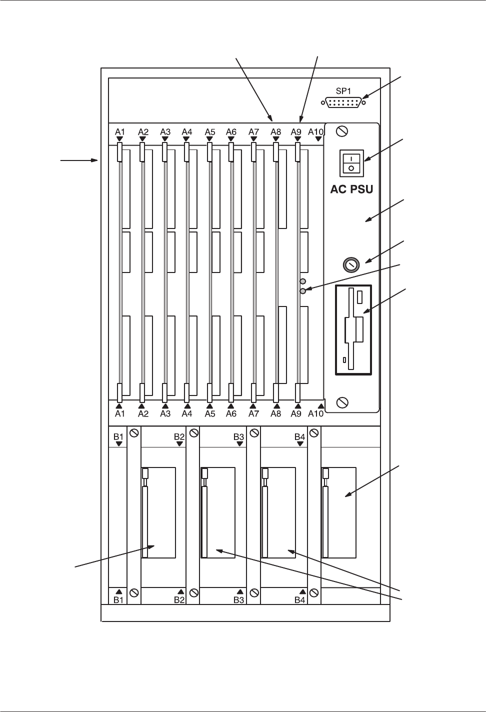
2-4
Installation and Maintenance
V
olume
Octel Overture 200/300 Serenade 3.0
PB60014–01
Figure 2-1
Octel Overture 200 Cabinet Shelf Structure, From the Front
Front System
Terminal Port
Power Supply
Unit
Floppy Diskette
Drive
Power Switch
System Fuse
W
orks for
Serenade Disk
Drive System/Voice
Disk Drives
Voice Disk
Drive
VCU Slot CPU Slot
Card Slots
A1 to A7
:
LIC, TLC, DAC, or
integration card
FAX card
LAN card
:
EntryWorks ACP
card
Reload Button
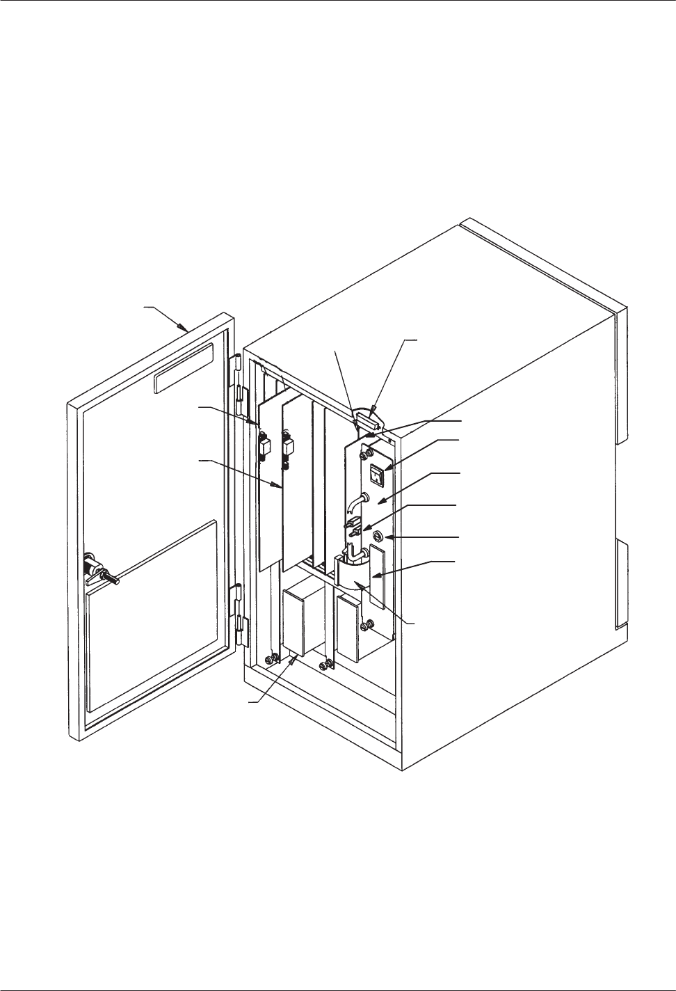
Hardware
2-5
Octel Overture 200/300 Serenade 3.0
PB60014–01
Figure 2-2
Octel Overture 200 Cabinet, Inside Front V
iew
Front Door
Disk Drive
Assembly
VCU
(Slot A8)
System Terminal Port
(SP1 Connector)
CPU (Slot A9)
ON/OFF Switch
Power Supply/
Floppy Drive Unit
Reload Button
Floppy Drive
Floppy Signal
Cable
Card Slot
Card Slot
Fuse

2-6
Installation and Maintenance
V
olume
Octel Overture 200/300 Serenade 3.0
PB60014–01
Figure 2-3
Octel Overture 200 Cabinet, Rear V
iew
RSĆ232C
Connector
(J2)
Alarm Port (J3)
I/O Panel
V
isual Mailbox
Connector (J4)
System
Terminal
Port (J1)
J1
J2
J3
J4
Power Cord P1P2P3P4P5P6P7
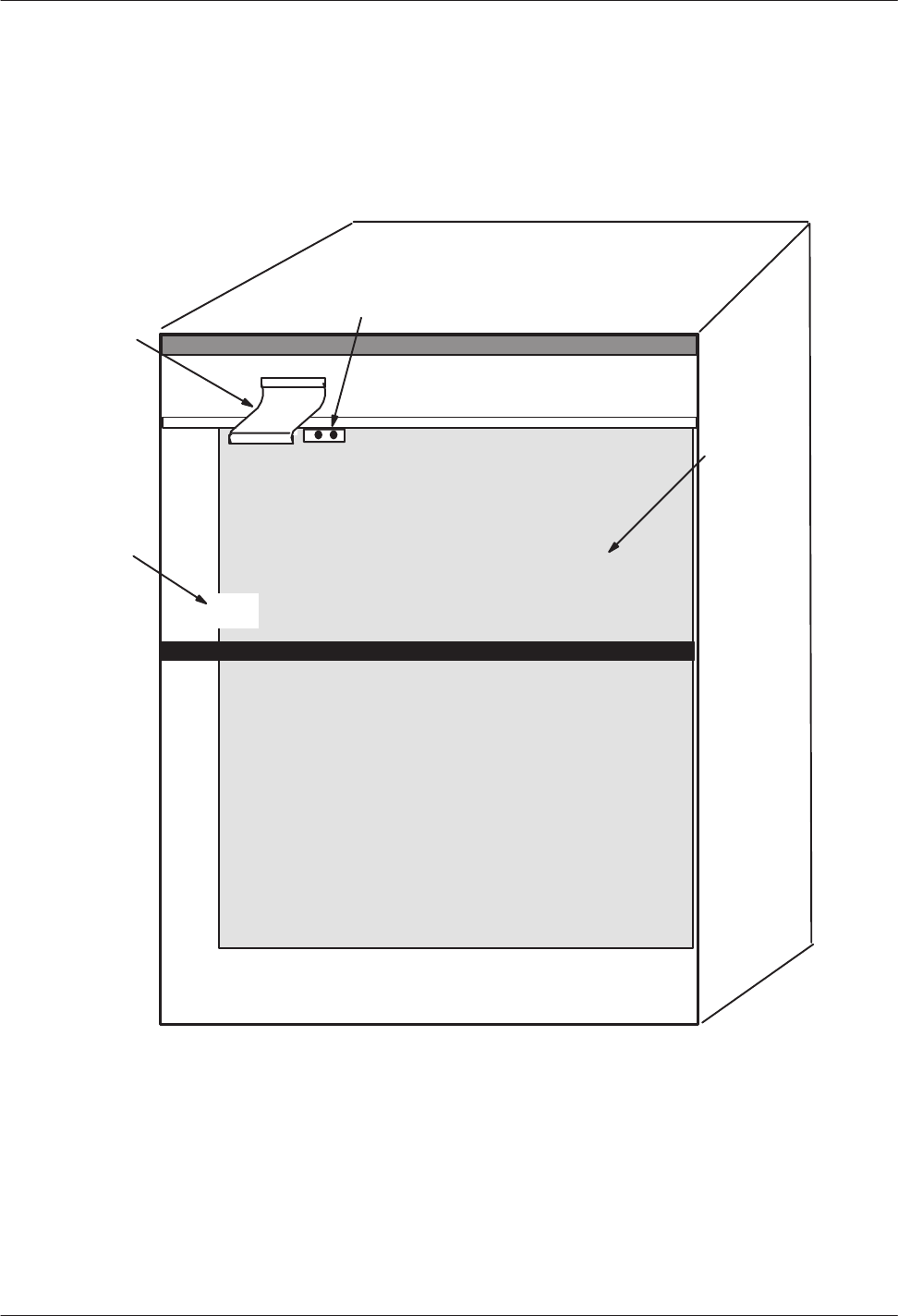
Hardware
2-7
Octel Overture 200/300 Serenade 3.0
PB60014–01
Figure 2-4
Octel Overture 200 Cabinet, Inside Rear V
iew
System
Terminal Port
Power Cord
Receptacle
Motherboard
Fan Power Harness
Connector

2-8
Installation and Maintenance
V
olume
Octel Overture 200/300 Serenade 3.0
PB60014–01
Octel
Overture 300 Cabinet
Each
Octel Overture 300 message server is shipped fully assembled. The cabinet specifications are as
follows:
Height:
37.5 inches (95.3 cm)
Width:
17.5 inches (44.5 cm)
Depth:
19.5 inches (49.5 cm)
Weight:
220 pounds (100 kg) maximum
Clearances
Front:
22 inches (55.9 cm)
Rear:
6 inches (15.2 cm)
Side:
1 inch (2.5 cm)
Top: none
The power line filter is located at the rear of the cabinet. The a.c. system power cord plugs into the
power line filter
. The power line filter prevents electromagnetic interference (EMI), from entering
the primary power lines. Some chassis disassembly is required to replace the power line filter
. The
voltage rating of the power line filter must agree with the input voltage rating of the power supply
unit (PSU).
In
–48 Vdc message servers, the power cord is integral with the power line filter
.
The outer metal enclosure contains three shelves, with slots for various configurations of disk drives
and system cards. Figure 2-5 through Figure 2-8 show various views and component locations for the
Octel Overture 300 message server
.
Shelf A
Shelf
A contains 15 card slots, with card slots A13–A15 reserved for the voice control unit (VCU) in
slot A13, the central processing unit (CPU) in slot A14, and the power supply unit (PSU) in slot A15.
The card slots in shelf A of the Octel Overture 300 cabinet could contain the following.
Slot
Number(s) Card T
ype/Other
A1–A11 LIC,
TLC, DAC,
or
integration cards
A1–A12
Fax card
A10–A12
LAN card
A12 EntryWorks
ACP card
VCU
A14 CPU
A15 PSU
Refer to the
Configuration
volume, Slots T
able, for information about configuring the slots.
Shelves B and C
The
slots in shelves B and C allow various configurations of Octel Overture 300 hard disk drives and
contain the message server
’
s load/backup device. The disk drive usage by slot number is as follows:

Hardware
2-9
Octel Overture 200/300 Serenade 3.0
PB60014–01
Slot
Number
T
ype of Disk Drive Installed
Shelf B
B1 Reserved
for future use
B2 W
orks for Serenade
disk drive
B3–B4 System/voice
disk drives (data and voice storage)
B5
Load/backup device
Shelf
C
C1–C4 Voice
disk drives (voice storage only)
The system/voice and voice disk drives are loaded into the slots in the following order: B3, B4, C1,
C2, C3, and C4. A single-drive message server has a system/voice drive installed in slot B3; a
two-drive message server has system/voice drives installed in slots B3 and B4; a three-drive message
server has system/voice drives installed in slots B3 and B4 and a voice drive installed in slot C1; and
so forth..
The Octel Overture 300 can be configured with 4-port, 8-port, or 16-port line cards, in any
combination of line cards, to a maximum of 128 ports. Refer to the
General Description
volume,
Product Description chapter
, General Sizing Consideration and Capacity section, for additional
information.
Other Components
The
washable air filter is inside the front door of the cabinet. The air intake is from the front, and air
exhaust is from the rear and top.
Octel
Overture 300
Fan Tray
Four
fans are located on a slide-out fan tray in the center of the cabinet, between shelves A and B.
The fan tray is a plug-in fan assembly used for system cooling. The fan assembly is accessible from
the front of the cabinet.
The four fans draw air through the front door air filter
, and they exhaust from the top rear and top
sides of the cabinet. The fans use 12 volts and are powered from the +12 VM output of the PSU. The
fans are not sensitive to the input power to the cabinet.
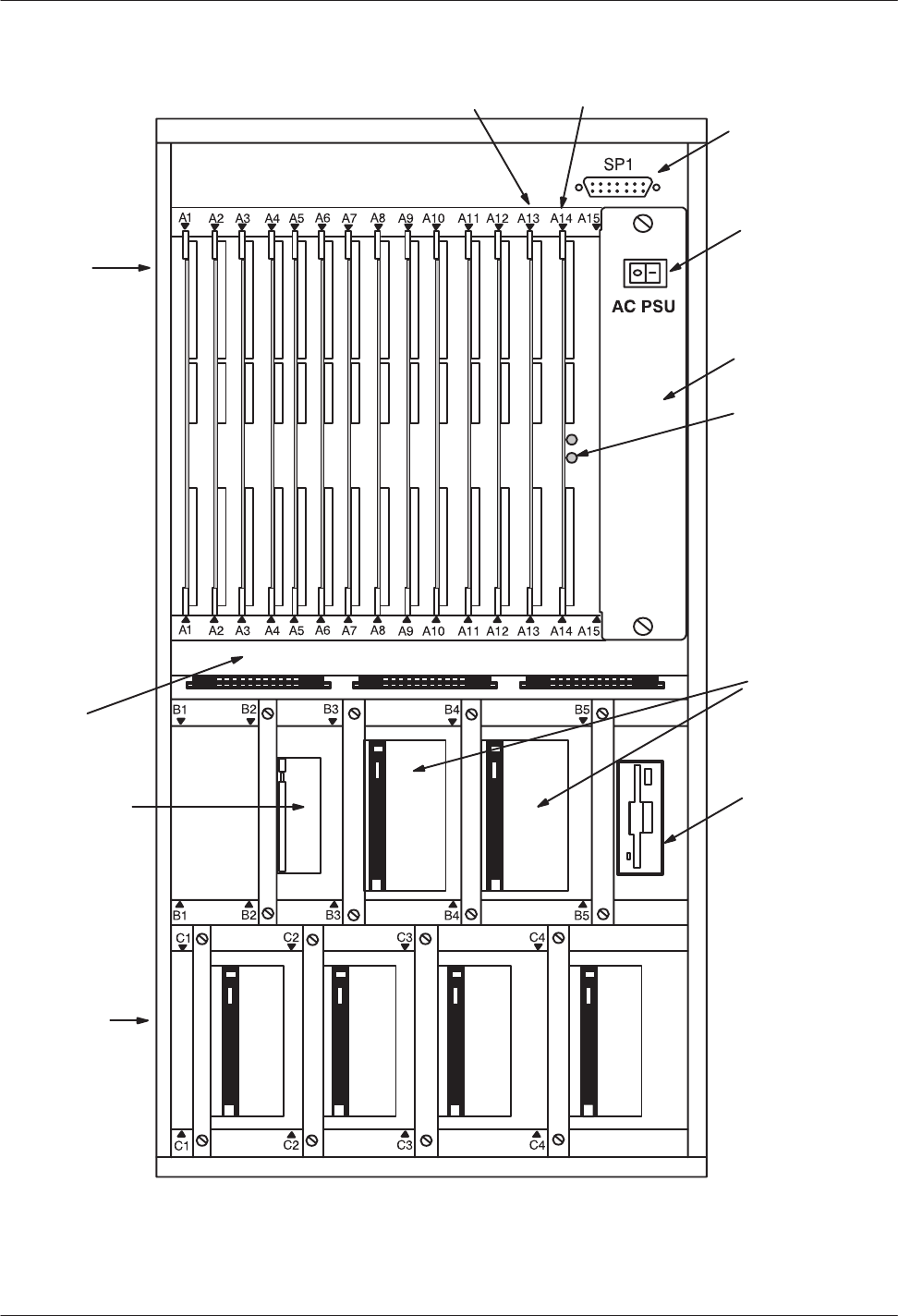
2-10
Installation and Maintenance
V
olume
Octel Overture 200/300 Serenade 3.0
PB60014–01
Figure 2-5
Octel Overture 300 Cabinet Shelf Structure, From the Front
Front
System
T
erminal Port
Power Supply
Unit
Floppy Diskette
Drive
Power Switch
W
orks for
Serenade Disk
Drive
Four Voice
Disk Drives
System/Voice
Disk Drives
Fan Tray
VCU Slot CPU Slot
Card Slots
A1 to A12
:
LIC, TLC, DAC,
or
Integration
card
FAX card
LAN card
:
EntryWorks ACP,
Reload Button
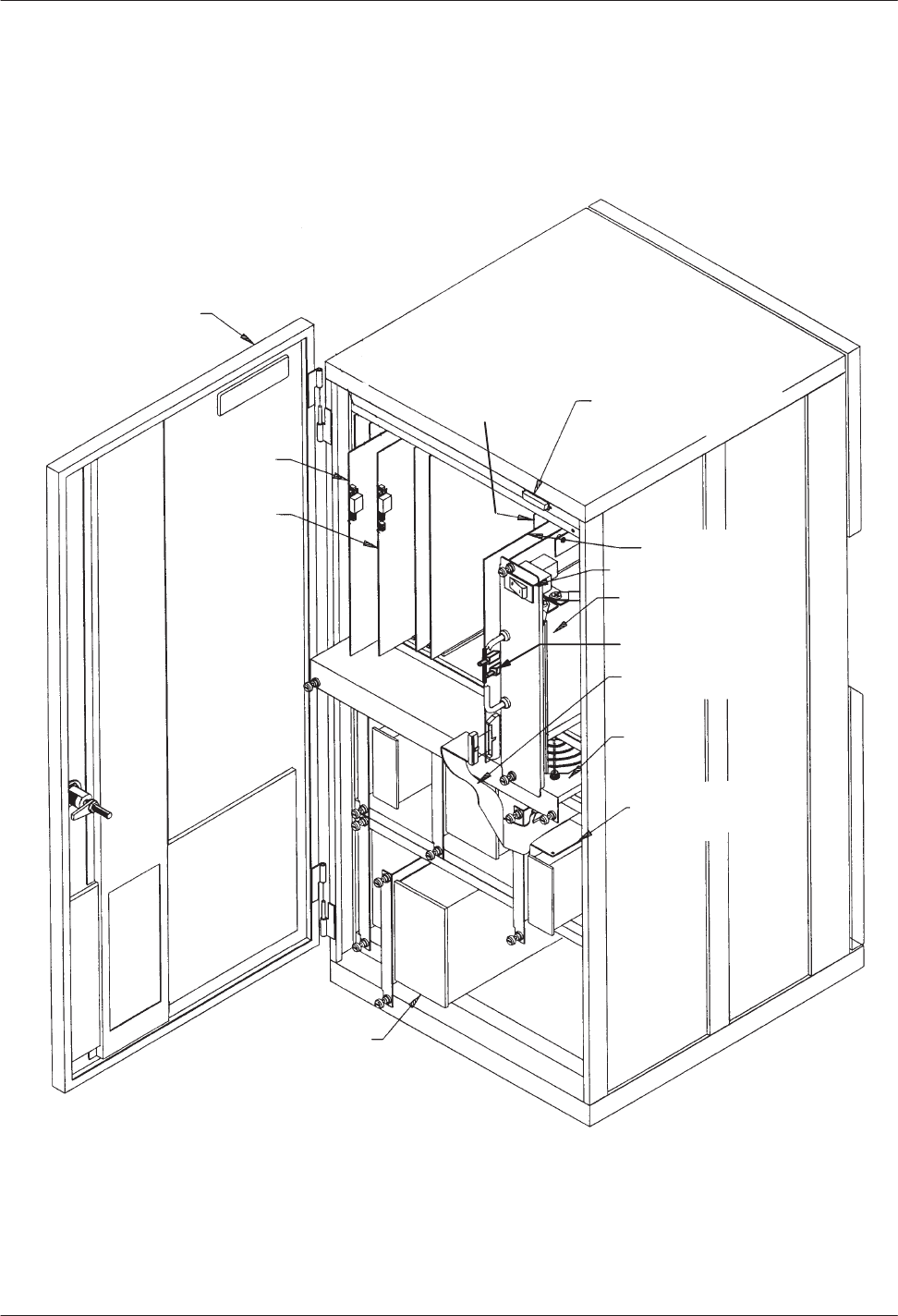
Hardware
2-1
1
Octel Overture 200/300 Serenade 3.0
PB60014–01
Figure 2-6
Octel Overture 300 Cabinet, Inside Front V
iew
Front Door
Card Slot
Card Slot
Hard Disk Drive
Assembly
VCU
(Slot A13)
Power Supply Unit
Fan Tray
System Terminal Port
(SP1 Connector)
CPU (Slot A14)
Floppy Signal Cable
ON/OFF Switch
Load/Backup Device
(Floppy Drive)
Reload Button
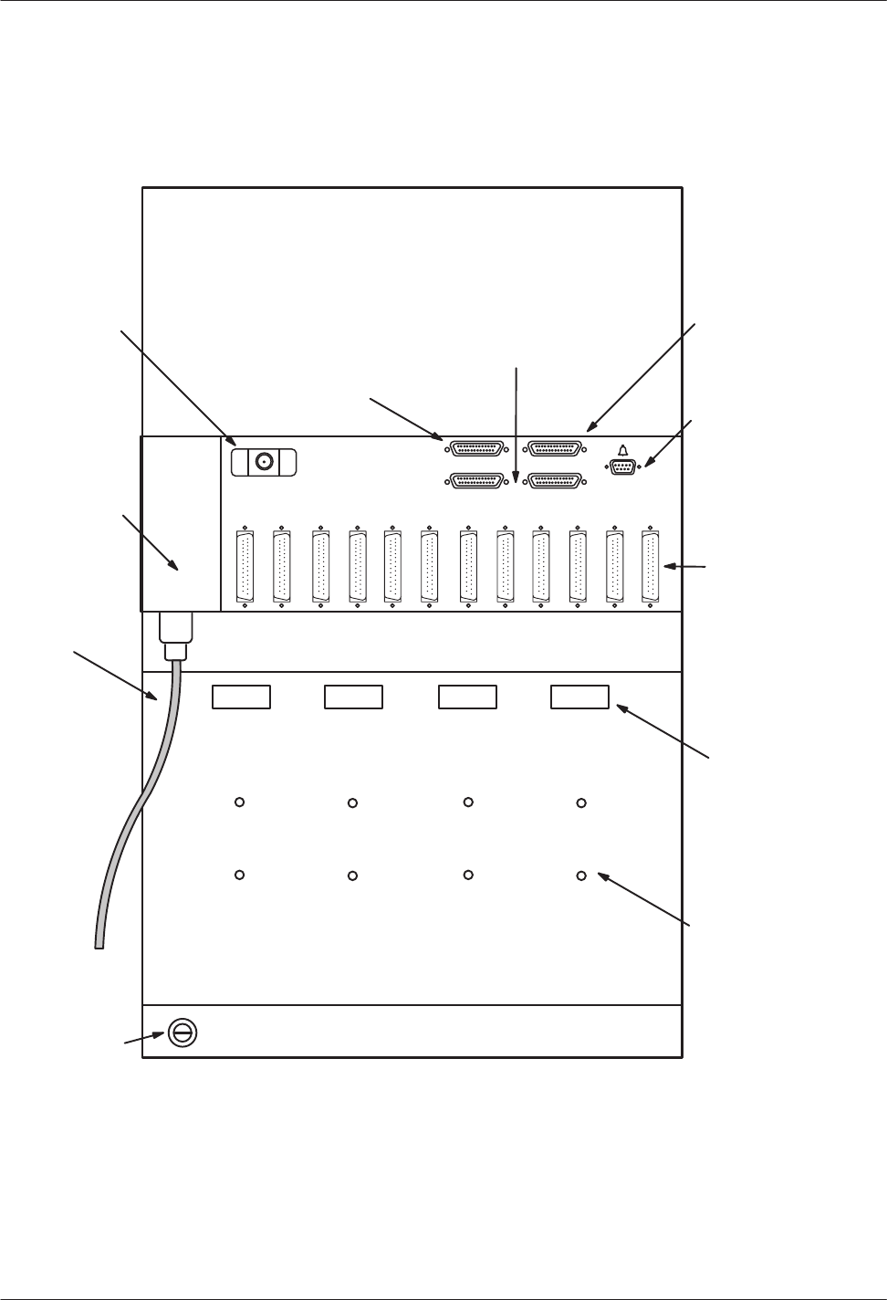
2-12
Installation and Maintenance
V
olume
Octel Overture 200/300 Serenade 3.0
PB60014–01
Figure 2-7
Octel Overture 300 Cabinet, Rear V
iew
J5
J4J3
J2J1
RSĆ232C
Connector
Port B (J2)
50Ćpin Telco
connectors
(25 pair) Amphenol
connectors
Power
Receptacle
Power
Cord
Alarm Port (J5)
P1P2P3
P4
P5P6P7P8P9P10P11P12
System Terminal Port
Rear Connection (J1)
Reserved
RSĆ232C
Connectors
(J3 and J4)
Earth Ground
Connection Point
J6
Visual Mailbox
Connector (J6)
Cable Tiedown
Points
Tapped Mounting
Holes for securing
W
orks for Serenade
Serial I/O panel
and
DAC panel
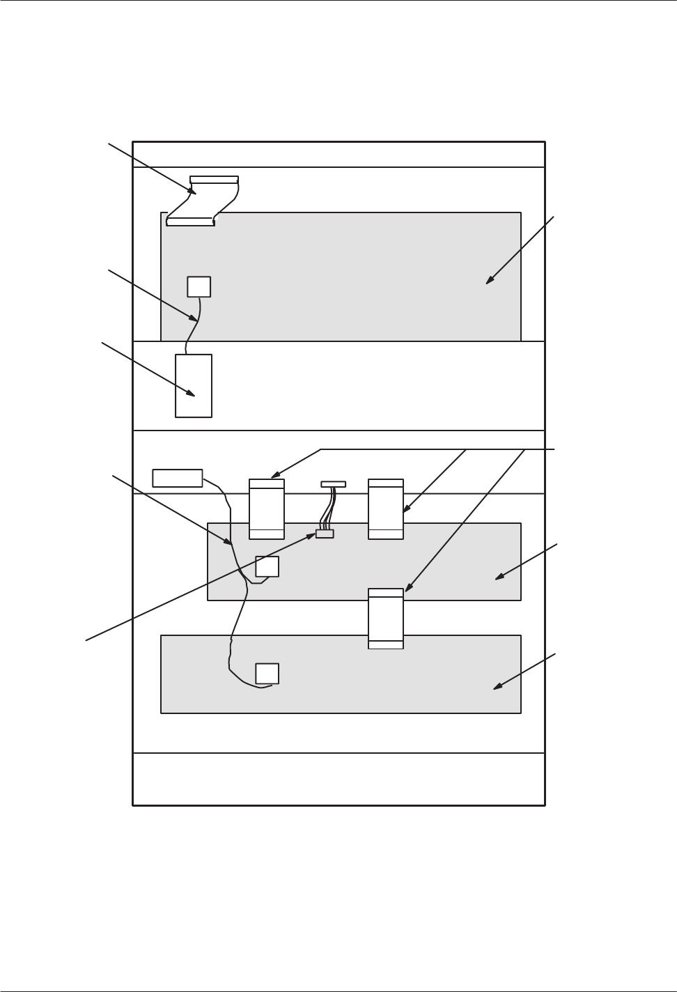
Hardware
2-13
Octel Overture 200/300 Serenade 3.0
PB60014–01
Figure 2-8
Octel Overture 300 Cabinet, Inside Rear V
iew
System Terminal
Port Cable
Main Power
Harness
Power Line
Filter
Main Disk Drive
Power Harness
Main
Motherboard
(shelf A)
Fan Tray
Power Harness
SCSI Bus
Jumper Cable
Disk Drive
Motherboard
(shelf B)
Disk Drive
Motherboard
(shelf C)

2-14
Installation and Maintenance
V
olume
Octel Overture 200/300 Serenade 3.0
PB60014–01
Subsystem Configurations
The
following tables list each subsystem name, abbreviation, part number
, and a brief description.
T
able 2-1 lists subsystems that are interchangeable between the Octel Overture 200 and the Octel
Overture 300 message server
. T
able 2-2 lists subsystems for the Octel Overture 200 message server
and T
able 2-3 lists subsystems for the Octel Overture 300 message server
. Following the last table
are more complete descriptions of the subsystems.
Table 2-1
Octel Overture 200/300 Subsystems
Subsystem Configurations
Part Number
Description
STORAGE
500-MB
Storage Drive
Overture 200 – 37/46 hours*
Overture 300 – 31/46 hours*
1.0-GB
Storage Drive
Overture 200 – 87/96 hours*
Overture 300 – 81/96 hours*
2.0-GB
Storage Drive
Overture 200 – 176/185 hours*
Overture 300 – 170/185 hours*
740-6632-002
740-6631-002
740-6633-002
Capacity
on Demand (COD), 0 hour drives.
SCSI hard disk drives for storage of voice
messages, prompts, system configuration data,
and software.
* The capacity is for message server overhead
and one language (slots 1 and 2) and full
capacity (slots 3–6). Subtract 1.2 hours for each
additional language.
LINE
INTERF
ACE CARDS (LIC)
United
States, Canada,
Mexico 300-6002-001
4-port, two-wire, loopstart telephone line
interface card (LIC4); 4 ports authorized.
300-6032-001
8-port, two-wire, loopstart telephone line
interface card (LIC8); 8 ports authorized.
300-6054-001
16-port, loopstart telephone line interface card
(DLC16); 0 ports authorized.
United Kingdom
300-6002-002
4-port, two-wire, loopstart telephone line
interface card; 4 ports authorized.
300-6032-002
8-port, two-wire, loopstart telephone line
interface card; 8 ports authorized.
300-6056-002
12-port, loopstart telephone line interface card
(ILC12); 0 ports authorized.
300-6054-002
16-port, telephone line interface card; 0 ports
authorized.
France, Belgium
300-6044-001
4-port, two-wire, loopstart telephone line
interface card; 4 ports authorized.
300-6054-017
16-port, loopstart telephone line interface card
(DLC16); 0 ports authorized.

Hardware
2-15
Octel Overture 200/300 Serenade 3.0
PB60014–01
Table 2-1
Octel Overture 200/300 Subsystems (continued)
Subsystem Configurations
Description
Part Number
Germany 300-6044-005 4-port,
two-wire, loopstart telephone line
interface card; 4 ports authorized.
300-6054-013
16-port, loopstart telephone line interface card
(DLC16); 0 ports authorized.
Netherlands 300-6002-009
300-6032-009
4-port, two-wire, loopstart telephone line
interface card; 4 ports authorized.
8-port, two-wire, loopstart telephone line
interface card; 8 ports authorized.
300-6054-009
16-port, loopstart telephone line interface card
(DLC16); 0 ports authorized.
New Zealand, Australia
300-6002-011
300-6032-011
4-port, two-wire, loopstart telephone line
interface card; 4 ports authorized.
8-port, two-wire, loopstart telephone line
interface card; 8 ports authorized.
300-6054-011
16-port, loopstart telephone line interface card
(DLC16); 0 ports authorized.
Direct Access Card (DAC)
300-6027-001
4-port, two-wire, loopstart telephone line
interface card. This card allows direct
connection of incoming DID or outgoing PBX
trunks.
New Zealand, Australia
Direct Access Card
300-6027-011
4-port, two-wire, loopstart telephone line
interface card. This card allows direct
connection of incoming DID or outgoing PBX
trunks.
Fax Application Processor
(Fax card)
300-6037-002
300-6037-003
4-channel fax processor that supports
communication with CCITT Group 3 fax
machines and operates at transmission rates of
up to 9600 baud.
8-channel fax processor that supports
communication with CCITT Group 3 fax
machines and operates at transmission rates of
up to 9600 baud.
LAN Card
300-6049-001
Used for Digital Networking, LAN Backup and
Restore, and Gateway Link. Interfaces with the
Octel Overture 200/300 by means of a 10BaseT
Ethernet interface.
W
orks for Serenade
ACP card
300-6019-002
Processor for W
orks for Serenade flow control
language. Includes host interface and ACP SCSI
disk drive control.

2-16
Installation and Maintenance
V
olume
Octel Overture 200/300 Serenade 3.0
PB60014–01
Table 2-1
Octel Overture 200/300 Subsystems (continued)
Subsystem Configurations
Description
Part Number
Telemarketing
Line Card
(TLC) 300-6032-003
8-port, two-wire, loopstart telephone line
interface card. Octel Overture 200/300 allows
recording by the first port of a TLC only if the
TLC is in slot 1.
United Kingdom
T
elemarketing Line Card
300-6032-004
8-port, two-wire, loopstart telephone line
interface card. Octel Overture 200/300 allows
recording by the first port of a TLC only if the
TLC is in slot 1.
Netherlands T
elemarketing
Line Card
300-6032-010
8-port, two-wire, loopstart telephone line
interface card. Octel Overture 200/300 allows
recording by the first port of a TLC only if the
TLC is in slot 1.
New Zealand, Australia
T
elemarketing Line Card
300-6032-012
8-port, two-wire, loopstart telephone line
interface card. Octel Overture 200/300 allows
recording by the first port of a TLC only if the
TLC is in slot 1.
A
T&T Integration Card
(ATTIC) 300-6018-001
Digital interface card to the A
T&T System 75,
System 85, and Definity PBXs. This connection
provides Adaptive Integration features.
ROLM Integration Card (RIC)
300-6025-001
Digital interface card to the ROLM 8000, 9000,
and 9751 PBXs. This connection provides
Adaptive Integration features.
Northern T
elecom SL-1
Integration Card (SLIC)
300-6009-001
Digital interface card to the Northern T
elecom
SL-1 and Meridian 1 PBXs. This connection
provides Adaptive Integration features.
Mitel Integration Card (MIC)
300-6020-001
Digital interface card to the Mitel SX-200
Digital, SX-100/SX-200 Analog
, SX-2000, and
SG PBXs.
Serial Integration Card for the
Meridian (SIC8)
300-6040-001
Digital interface card to the Northern T
elecom
Meridian 1 PBX. This connection provides
Adaptive Integration features.
APIC Integration Card for
A
T&T Systems
300-6058-003
12-port interface card to the AT&T System 75,
System 85, and Definity PBX; 0 ports
authorized.
NPIC Integration Card for
Northern T
elecom Systems
300-6058-004
16-port interface card to the Northern T
elecom
Meridian 1 and Meridian SL-1 PBX; 0 ports
authorized.
V
oice Control Unit (VCU)
300-6001-004
File system manager
, SCSI bus control, and
voice bus control.
Central Processing Unit (CPU)
300-6039-003
Central control processor that runs call
processing software.

Hardware
2-17
Octel Overture 200/300 Serenade 3.0
PB60014–01
Table 2-1
Octel Overture 200/300 Subsystems
Subsystem Configurations
Description
Part Number
Works
for Serenade
Hard Disk
Drive 740-6248-001
SCSI hard disk drive for storage of W
orks for
Serenade programs and databases.
W
orks for Serenade Serial I/O
Cable 520-6007-001
Cable connecting the EntryWorks ACP board to
the W
orks for Serenade serial I/O panel.
W
orks for Serenade External
Modem SA10194-03
Dedicated external modem for remote access to
the W
orks for Serenade subsystem.
W
orks for Serenade Modem
Cable SA10187-01
Cable between the W
orks for Serenade modem
and the serial I/O panel.
Option Control Chip (OCC)
FK90087
Contains information about the software options
the Octel Overture 200/300 is equipped with.
Table 2-2
Octel Overture 200 Subsystems
Subsystem Configurations
Part Number
Description
Motherboard
(MB)
740-6503-001
Backplane board for interconnecting system
modules and system power distribution.
Power Supply Units (PSU)
90-132 V
AC
180-260 V
AC
42-60 VDC
740-6504-001
740-6505-001
740-6506-001
Power conversion from system input power to
four regulated, d.c. voltages. The load/backup
device is part of the PSU.
W
orks for Serenade Serial I/O
Panel 740-6037-002 Rear
-mount RS-232C connector panel.
DC Inlet Box
740-6537-002
Inlet box for d.c. powered systems.
Fan Panel Assembly
740-6502-002
System cooling fans.
Air Filter
840-6507-001 W
ashable air filter
.

2-18
Installation and Maintenance
V
olume
Octel Overture 200/300 Serenade 3.0
PB60014–01
Table 2-3
Octel Overture 300 Subsystems
Subsystem Configurations
Part Number
Description
Load/Backup
Device, Floppy
Disk Drive
740-6010-001
Removable media drive for system configuration
backup, and software and prompt loading during
an upgrade.
Motherboards (MB)
Shelf A
Shelf B
Shelf C
740-6003-001
300-6006-001
300-6005-001
Backplane boards for interconnecting system
modules and system power distribution.
Power Supply Unit (PSU)
90–132 V
ac
180–260 V
ac
42–60 Vdc
740-6016-001
740-6017-001
740-6027-001
Power conversion from system input power to
six regulated d.c. voltages.
Fan T
ray Assembly
740-6002-001
System cooling fans.
Air Filter
840-6013-001 W
ashable air filter
.
W
orks for Serenade Serial I/O
Panel 740-6043-002
Rear mount RS-232C connector panel.
DAC Power Supply Assembly
740-6050-001
Provides 48 Vdc to DAC I/O panel.
DAC I/O Panel
740-6051-002
Concentrates lines from up to four DAC boards
into connector
.
Line
Interface Cards
Line interface cards (LIC) provide a computer
-controlled interface to the PBX extensions. The
dif
ferent types of line cards used in the Octel Overture 200/300 configuration are as follows:
LIC4
LIC8
DLC16
ILC12
Each 4-, 8-, 12 or 16-port line card connects to PBX extensions through a 25-pair cable. The 4-port
and 8-port LICs are based on the original D.I.A.L. software technology
. The DLC16 and ILC12 cards
are based on the digital signal processing (DSP) technology to interface with analog
ports.
The LIC4, LIC8, and DLC16 are FCC part 68 registered. The LIC4, LIC8, DLC16, and ILC12 are
BABT
-approved for use in the United Kingdom.

Hardware
2-19
Octel Overture 200/300 Serenade 3.0
PB60014–01
Each
LIC contains the necessary circuitry for ring detection, dial tone detection, and signal power
measurement, allowing automatic gain control from 0 dB to 24 dB of gain for recording messages.
The LIC contains a yellow LED for each port, which indicates port activity
.
In the Octel Overture 200, line cards can occupy slots A1 through A6.
In the Octel Overture 300, line cards can occupy slots A1 through A1
1.
Telemarketing Line Card (TLC)
The
telemarketing line card is an 8-port line card. It differs from the LIC, because only the first port
of the TLC located in slot A1 can be used for recording. The seven remaining ports of the TLC in
slot one are play-only ports. All other TLC ports in the message server are play-only ports. When
recording is attempted on other ports, the Octel Overture 200/300 prompts
“Messages may not be
recor
ded at this time. No storage is available.”
The first TLC must be installed in slot A1. Standard line cards can be installed in slots beyond the
TLC cards. The TLC is FCC part 68 registered.
In the Octel Overture 200, the TLC can occupy slots A1 through A6.
In the Octel Overture 300, the TLC can occupy slots A1 through A1
1.
Direct
Access Card (DAC)
The
direct access card (DAC) is an optional, 4-port interface card. When used in place of the standard
LIC, the DAC allows the direct connection of incoming DID or outgoing PBX trunks. The DAC
requires an external –48-Vdc PSU and a rear
-mounted DID I/O panel.
In the Octel Overture 200, the DAC can occupy slots A1 through A6.
In the Octel Overture 300, the DAC can occupy slots A1 through A1
1.
EntryWorks ACP Card
The
EntryW
orks ACP card is the application control processor for the W
orks for Serenade
flow
control language. It includes the host interface and the ACP SCSI disk drive control.
In the Octel Overture 200, the EntryW
orks ACP must occupy slot A7.
In the Octel Overture 300, the EntryW
orks ACP must occupy slot A12.
EntryWorks
also requires the following:
EntryW
orks disk drive
EntryWorks
serial I/O panel and cable
EntryW
orks external modem and cable

2-20
Installation and Maintenance
V
olume
Octel Overture 200/300 Serenade 3.0
PB60014–01
Fax Application Processor
The
fax application processor is a fax card that transmits and receives fax messages for the Fax Mail
Plus feature. The fax processor contains one or two 4-channel fax daughter boards and supports up to
eight simultaneous fax transactions when both daughter boards are installed. It supports communication
with CCITT Group 3 fax machines. The fax channels operate at transmission rates up to 9600 baud.
In the Octel Overture 200, the fax card can occupy slots A1 through A7. The total number of fax
channels cannot exceed the number of voice ports.
In the Octel Overture 300, the fax card can occupy slots A1 through A12. The total number of fax
channels cannot exceed the number of voice ports.
LAN
Card
The
LAN card is required for both Remote and Domain Digital Networking, the LAN Backup and
Restore feature, and Gateway Link applications. The card interfaces with the Octel Overture 200/300
by means of a 10BaseT Ethernet interface.
In the Octel Overture 200, the LAN card can occupy slots A5 through A7.
In the Octel Overture 300, the LAN card can occupy slots A10 through A12.
Integration
Cards
Integration
cards are used with certain PBX integrations that utilize proprietary digital links. Four
types of integration cards are available:
AT&T (A
TTIC), ROLM (RIC), Northern Telecom SL-1 (SLIC) integration card. Each
integration card is divided into two integration units; each integration unit supports two
integration links.
PIC integration cards with COD ports
MIC integration cards
SIC8 integration cards
In the Octel Overture 200, integration cards can occupy slots A1–A6.
In the Octel Overture 300, most integration cards can occupy slots A1–A1
1.
AT&T Integration Card (ATTIC)
The
A
T&T Integration Card (A
TTIC) is used with AT&T System 75, System 85, and Definity
integrations. Refer to the Integration
volume, A
T&T System Adaptive Integration.

Hardware
2-21
Octel Overture 200/300 Serenade 3.0
PB60014–01
ROLM Integration Card (RIC)
The
ROLM Integration Card (RIC) is used with ROLM integrations. Refer to the
Integration
volume, ROLM Adaptive Integration chapter.
Northern Telecom SL-1 Integration Card (SLIC)
The
Northern T
elecom SL-1 Integration Card (SLIC) is used with Northern T
elecom SL-1 and
Meridian 1 integrations. Refer to the Integration
volume, SL-1 Adaptive Integration chapter
.
PIC Integration Card for AT&T (APIC)
The
APIC Integration Card is used with A
T&T System 75, System 85, and Definity PBX
integrations. W
ith APIC, the integration and line card functionality are combined on each port. The
APIC card is a 12-port COD card. The ports can be purchased in increments. Refer to the
Integration
volume, A
T&T System Adaptive Integration W
ith APIC chapter
.
PIC Integration Card for Northern Telecom (NPIC)
The
NPIC Integration Card is used with Northern T
elecom Meridian 1 or Meridian SL–1 PBX
integrations. W
ith NPIC, the integration and line card functionality are combined on each port. The
NPIC card is a 16-port COD card. The ports can be purchased in increments. Refer to the
Integration
volume, Northern T
elecom Adaptive Integration W
ith NPIC chapter
.
Mitel Integration Card (MIC)
The
Mitel Integration Card (MIC) is used with Mitel SX-200 Digital, SX-100/SX-200 Analog
and
SX-2000 S and SG integrations. Refer to the
Integration volume, Mitel Adaptive Integration chapter
.
Serial Integration Card for the Meridian 1 (SIC8)
The
Serial Integration Card (SIC8) is used with Northern T
elecom Meridian 1 PBX integrations.
Refer to the
Integration volume, Meridian 1 Adaptive Integration chapter
.
Voice Control Unit (VCU)
The
Voice Control Unit (VCU) manages the system/voice and voice disk drives. The VCU is
responsible for manipulating and controlling all voice data files. It controls the loopstart line
interface cards and preprocesses events from the LICs before passing the events to the CPU.
On the Octel Overture 200, the VCU is located in slot A8 and manages the system/voice and voice
disk drives in slots B2, B3, and B4.
On the Octel Overture 300, the VCU is located in slot A14 and manages the system/voice and voice
disk drives in slots B3, B4, and C1–C4.

2-22
Installation and Maintenance
V
olume
Octel Overture 200/300 Serenade 3.0
PB60014–01
Central Processing Unit (CPU)
The
central processing unit (CPU) is the master control unit for the Octel Overture 200/300. The
CPU controls the VCU and the optional integration cards. The CPU contains four serial I/O ports.
The first serial port is shared between the internal modem and the system terminal port, which is
accessed at the rear connector J1 or the front connector SP1. As a modem port, the first serial port
can be connected to any telephone port under system software control. The internal modem is a Bell
103A-compatible (300 baud)/Bell 212A and CCITT V
.22-compatible (1200 baud)/CCITT V
.22
bis-compatible (2400 baud) modem and RS-232C serial connection.
The second port can either communicate with the optional DID/E&M T
runk Interface via an
RS-232C cable or be used for RS-232C adaptive integration for message waiting and passing call
information from some PBXs. Refer to the
Integration
volume, Adaptive Integration chapter
.
On the Octel Overture 200, the CPU is located in slot A9. The CPU provides relay closure contacts
for major and minor alarms on J3.
On the Octel Overture 300, the third and fourth ports, accessed through J3 and J4, are reserved for
future use. The CPU provides relay closure contacts for major and minor alarms on J5.
The CPU also contains the following:
On the Octel Overture 200, a floppy disk controller controls the floppy disk residing in the PSU.
On the Octel Overture 300, a floppy disk controller controls the floppy disk residing in slot B5.
The message-server time-of-day clock is backed up by battery. The battery can keep the clock
running for up to 1 week if the power fails.
The message-server TDM crosspoint switch controls the TDM bus.
An Analog
-to-digital converter (A to D) monitors message-server voltages and temperature.
Power Supply Unit (PSU)
The
power supply unit (PSU) is a plug-in unit with three nominal input voltages available for the PSU:
90–132 V
ac (1
10 V
ac nominal)
180–260 V
ac (230 V
ac nominal)
42–60 Vdc (–48 Vdc nominal)
A PSU with the correct input voltage must be used. Do not install or remove the PSU with the circuit
breaker in the ON position.
On the Octel Overture 200, the PSU is located in slot A10. The message server input voltage is
displayed near the power cord socket at the rear of the cabinet and on the PSU.
On the Octel Overture 300, the PSU is located in slot A15. The message server input voltage is
displayed on the power line filter at the rear of the cabinet.
For the Octel Overture 300, refer to the Installation chapter
, Installation Requirements section, for
instructions to install an
Octel Overture 300 powered by a –48-Vdc PSU. Refer to the Hardware
Replacement, Power Supply Unit section, in this manual for instructions about removing and
installing a PSU.

Hardware
2-23
Octel Overture 200/300 Serenade 3.0
PB60014–01
The
PSU provides regulated d.c. voltages. The voltages are shown in T
able 2-4.
Table 2-4
Power Supply Unit d.c. V
oltages
Name Nominal d.c. Voltage Function
+5 V 5 volts
Digital logic power
+5 VC 5 volts
Analog circuit power
+12 VM 12 volts
Fan and disk drive motor power
+12 VC 12 volts Analog
circuit power
ć12 VC ć12 volts Analog
circuit power
ć5 VC ć5 volts Analog
circuit power
The PSU provides the system power fail signal. This signal is activated if the message-server input
voltage drops out of operational range. The power fail signal interrupts the CPU as a warning of loss
of primary power
, allowing controlled shutdown of the Octel Overture 200/300.
On the Octel Overture 200, the PSU provides a protective fuse for primary power production. This
fuse is opened when a primary overcurrent occurs. The PSU contains a spare fuse.
On the Octel Overture 200, the +5-volt PSU is sensed at the center of the motherboard. Each
regulated voltage of the PSU includes overvoltage and overcurrent protection. The PSU also includes
overtemperature protection.
On the Octel Overture 300, the PSU provides the message server reset signal. This signal is activated
at power up and resets all boards in the message server
. The PSU provides a protective circuit breaker
for primary power
. This circuit breaker also acts as the message server power switch. The circuit
breaker is tripped for primary overcurrent, power supply overtemperature, and secondary overvoltage.
On the Octel Overture 300, the +5-volt PSU is sensed at the center of the shelf A motherboard. The
+12-volt fan and drive motor power is sensed at the SCSI motherboard B and SCSI motherboard C.
Each regulated voltage of the PSU includes overvoltage and overcurrent. The PSU also includes
overtemperature protection. In the case of an overtemperature occurrence, the circuit breaker opens.
Motherboard
The Octel Overture 200 has one motherboard. The Octel Overture 300 has three motherboards, one
each for shelves A, B, and C.
Octel Overture 200/300 Motherboard
The
motherboard is installed in the rear of the cabinet and distributes d.c. power to the cards, disks,
and fans.
The motherboard includes signal interconnections from slots A1 through A7 on shelf A to the rear
connectors P1 through P7, respectively
. These connectors are used for external circuit connections to
cards installed in the respective slots. For example, a line card installed in slot A1 connects to
tip-and-ring circuits of a telephone network through rear connector P1.

2-24
Installation and Maintenance
V
olume
Octel Overture 200/300 Serenade 3.0
PB60014–01
The
motherboard includes signaling for two separate SCSI buses on shelf B: the system/voice SCSI
bus and the W
orks for Serenade
SCSI bus. The system/voice SCSI bus interconnects slots B2 through
B4. The W
orks for Serenade
SCSI bus connects to slot B1. The motherboard includes an ID signal
field for each slot. This ID field is used by the plug-in disk assemblies for SCSI bus ID selection.
The message server motherboard provides the reset signal. This signal is activated when the power is
turned on, which resets all boards in the message server
.
Octel Overture 300 Motherboards
Shelf
A Motherboard
The
main motherboard is installed in shelf A and distributes d.c. power to shelf A cards.
The shelf A motherboard includes signal interconnections from slots A1 through A12 to connectors
P1 through P12, respectively
. These connectors are used for external circuit connections to cards
installed in the respective slots. For example, a line card installed in slot A1 connects to tip-and-ring
circuits of a telephone network through connector P1.
Shelf
B Motherboard
The
shelf B motherboard includes signaling for two separate SCSI buses: the system/voice SCSI bus
and the W
orks for Serenade
SCSI bus. The system/voice SCSI bus interconnects slots B3 through B5.
The W
orks for Serenade
SCSI bus interconnects slots B1 and B2. This motherboard distributes
+5-volt and +12-volt power to slots B1 through B5. It includes an ID signal field for each slot. This
ID field is used by the plug-in disk assemblies for SCSI bus ID selection.
Slot B5 is used for the load/backup device and includes SCSI bus signal connections and power
connections. In the case of a floppy device installed in this slot, only power is provided from the
motherboard to the floppy device. The floppy device does not use the SCSI connection.
The shelf B motherboard provides a +12-volt power connection to the fan tray
.
Shelf
C Motherboard
The
shelf C motherboard provides a system/voice SCSI bus connection, power distribution, and ID
signals to disk assemblies installed in slots C1 through C4.
Option Control Chip (OCC)
The
Option Control Chip (OCC) is located on the motherboard, directly behind the PSU.
For the Octel Overture 300, the OCC is on the shelf A motherboard.
The OCC contains information about the message-server configuration, the number of voice and fax
mailboxes authorized, and the feature options the Octel Overture 200/300 is equipped with.
The OCC must always remain with the message server it was purchased for
.
If the motherboard must
be replaced, the OCC must be transferred from the old motherboard to the replacement motherboard.
Refer to the Hardware Replacement, Option Control Chip Replacement section, in this manual.

Hardware
2-25
Octel Overture 200/300 Serenade 3.0
PB60014–01
Works
for Serenade
Hard Disk
The
EntryW
orks
hard disk is a SCSI-technology hard disk. It is used to store EntryW
orks
programs
and databases.
In the Octel Overture 200, the EntryW
orks
hard disk occupies slot B1.
In the Octel Overture 300, the EntryW
orks
hard disk occupies slot B2.
Octel
Overture 300 Load/Backup Device
The
load/backup device is the floppy-disk drive, which permits online backup storage of critical
message server configuration information and software. It also offers a rapid and reliable means of
copying new software to the hard disk. The floppy-disk drive is also used to restore a message server
to normal operation when replacing the hard disk.
The floppy-disk drive is connected to the CPU by a cable to the front of the CPU.
Hard
Disk Drives
Disk
assemblies are plug-in, random access, read/write magnetic hard-disk assemblies, requiring no
adjustments or jumper configurations.
The Octel Overture 200/300 cabinet uses SCSI technology hard-disk drives that interface to a single
SCSI bus. This bus is controlled by the VCU. Disk drives are used for two functions:
System/Voice
disks store the operating message server programs, voice prompts, configuration
information, and voice messages. A portion of a system/voice disk is reserved for system
software, configuration data, and prompts. The remainder of the drive is used for voice message
storage.
V
oice storage
disks store only voice messages.
Depending on capacity and redundancy requirements, each Octel Overture 200/300 contains one or
more hard-disk drives.
The Octel Overture 200 message servers can contain from one to three hard-disk drives in slots
B2, B3, and B4.
The Octel Overture 300 message servers can contain from one to six hard-disk drives in slots B3,
B4, C1, C2, C3, and C4.
The first disk drive is always a system/voice disk. If a second disk is installed, it is also a
system/voice disk. If additional disk drives are installed, they are voice disks
only.
The maximum disk storage for an
Octel Overture 200 message server is 540 hours of voice storage.
The maximum disk storage for an
Octel Overture 300 message server is 1085 hours of voice storage.
Disk-storage space for recorded messages, names, greetings, redundancy and feature applications is
purchased in 5-hour increments. Storage hours are upgraded by Octel Customer Administration.

2-26
Installation and Maintenance
V
olume
Octel Overture 200/300 Serenade 3.0
PB60014–01
Disk Redundancy
Hot
Standby redundancy of all system software, configuration data, and prompts is automatically
provided when a second system disk is installed. Hot Standby redundancy is not available when only
one system disk is installed.
Optional software enhancements offer redundancy for names, greetings, and messages for any
message server containing two or more disk drives. When Names and Greetings Redundancy and
Message Redundancy are installed, names, greetings, and messages are made redundant in the
following manner:
In message servers containing two disk drives, the redundancy is on the second drive.
In message servers containing more than two disk drives, the redundancy is on any drive, spread
out over all equipped drives.
Refer to the
Featur
e Description
volume, Hard Disk Redundancy chapter
.

Octel
Overture 200/300 Serenade 3.0
PB60014–01
3
PREPARING
THE PHONE SYSTEM
3.1 How
the Octel Overture 200/300 W
orks with the Phone System
3-1.
. . . . . . . . . . . . . . . . . . . . . . . . . . . . . . . . . . .
Interfaced
Installations
3-1.
. . . . . . . . . . . . . . . . . . . . . . . . . . . . . . . . . . . . . . . . . . . . . . . . . . . . . . . . . . . . . . . . . .
Integrated
Installations
3-2.
. . . . . . . . . . . . . . . . . . . . . . . . . . . . . . . . . . . . . . . . . . . . . . . . . . . . . . . . . . . . . . . . . .
Answering
Incoming Calls
3-3.
. . . . . . . . . . . . . . . . . . . . . . . . . . . . . . . . . . . . . . . . . . . . . . . . . . . . . . . . . . . . . . .
Acting
as a Message Center
3-4.
. . . . . . . . . . . . . . . . . . . . . . . . . . . . . . . . . . . . . . . . . . . . . . . . . . . . . . . . . . . . .
Using
the DID/E&M Trunk Interface
3-4.
. . . . . . . . . . . . . . . . . . . . . . . . . . . . . . . . . . . . . . . . . . . . . . . . . . . . . . .
3.2 Determining Necessary Changes 3-5.
. . . . . . . . . . . . . . . . . . . . . . . . . . . . . . . . . . . . . . . . . . . . . . . . . . . . . . . . . . . . .
3.3 Changes
to Central Of
fice T
runking 3-6.
. . . . . . . . . . . . . . . . . . . . . . . . . . . . . . . . . . . . . . . . . . . . . . . . . . . . . . . . . . .
Additional
T
runking 3-6.
. . . . . . . . . . . . . . . . . . . . . . . . . . . . . . . . . . . . . . . . . . . . . . . . . . . . . . . . . . . . . . . . . . . . .
Splitting
T
runk Groups 3-6.
. . . . . . . . . . . . . . . . . . . . . . . . . . . . . . . . . . . . . . . . . . . . . . . . . . . . . . . . . . . . . . . . . .
DID
T
runks: Using the DID/E&M T
runk Interface
3-6.
. . . . . . . . . . . . . . . . . . . . . . . . . . . . . . . . . . . . . . . . . . . .
Ordering PE T
runking Changes
3-7.
. . . . . . . . . . . . . . . . . . . . . . . . . . . . . . . . . . . . . . . . . . . . . . . . . . . . . . . . . . .
3.4 Phone
System Configuration
3-8.
. . . . . . . . . . . . . . . . . . . . . . . . . . . . . . . . . . . . . . . . . . . . . . . . . . . . . . . . . . . . . . . . .
Port Extensions 3-8.
. . . . . . . . . . . . . . . . . . . . . . . . . . . . . . . . . . . . . . . . . . . . . . . . . . . . . . . . . . . . . . . . . . . . . . . .
Called Extensions 3-9.
. . . . . . . . . . . . . . . . . . . . . . . . . . . . . . . . . . . . . . . . . . . . . . . . . . . . . . . . . . . . . . . . . . . . . .
Trunks 3-9
. . . . . . . . . . . . . . . . . . . . . . . . . . . . . . . . . . . . . . . . . . . . . . . . . . . . . . . . . . . . . . . . . . . . . . . . . . . . . . . . .
Trunk
Redirection
3-9.
. . . . . . . . . . . . . . . . . . . . . . . . . . . . . . . . . . . . . . . . . . . . . . . . . . . . . . . . . . . . . . . . . . . . . . .
Trunk
Selection
3-10.
. . . . . . . . . . . . . . . . . . . . . . . . . . . . . . . . . . . . . . . . . . . . . . . . . . . . . . . . . . . . . . . . . . . . . . .
Ordering
Phone System Changes
3-10.
. . . . . . . . . . . . . . . . . . . . . . . . . . . . . . . . . . . . . . . . . . . . . . . . . . . . . . .
3.5 Implementing
the Octel Overture 200/300 on PBXs without DIL Feature
3-12.
. . . . . . . . . . . . . . . . . . . . . . . . . . .
Upgrade
the PBX to a Feature Package Of
fering the DIL Feature
3-13.
. . . . . . . . . . . . . . . . . . . . . . . . . . . .
Use DID Numbers 3-13.
. . . . . . . . . . . . . . . . . . . . . . . . . . . . . . . . . . . . . . . . . . . . . . . . . . . . . . . . . . . . . . . . . . . . .
Place
the Console in Night Mode
3-13.
. . . . . . . . . . . . . . . . . . . . . . . . . . . . . . . . . . . . . . . . . . . . . . . . . . . . . . . .
Arrange
for T
runks to Call Divert to the Octel Overture 200/300 Ports
3-13.
. . . . . . . . . . . . . . . . . . . . . . . . .
Figures
3-1 Octel
Overture 200/300 Connection to Phone System
3-1.
. . . . . . . . . . . . . . . . . . . . . . . . . . . . . . . . . . . . . . . . . . .
3-2 All
Incoming Lines Directed to the Octel Overture 200/300
3-3.
. . . . . . . . . . . . . . . . . . . . . . . . . . . . . . . . . . . . . . .
3-3 Incoming
Calls Split Between Console and the Octel Overture 200/300
3-3.
. . . . . . . . . . . . . . . . . . . . . . . . . . . .
3-4 Sample
Agency Letter for PE Changes
3-7.
. . . . . . . . . . . . . . . . . . . . . . . . . . . . . . . . . . . . . . . . . . . . . . . . . . . . . . . .
3-5 Service
Provider Letter
3-11.
. . . . . . . . . . . . . . . . . . . . . . . . . . . . . . . . . . . . . . . . . . . . . . . . . . . . . . . . . . . . . . . . . . . . .
3-6 Directing
Incoming Calls to the Octel Overture 200/300 When the PBX Does Not Of
fer a DIL Feature
3-12.
.
Table
3-1 PBX
Features to Direct Trunks to the Octel Overture 200/300
3-10.
. . . . . . . . . . . . . . . . . . . . . . . . . . . . . . . . . . . .
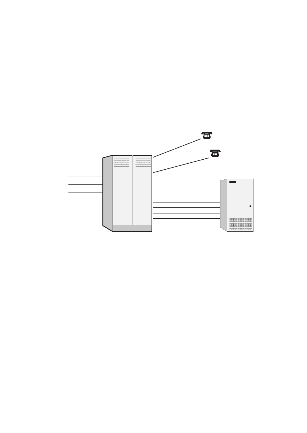
Preparing
the Phone System 3-1
Octel Overture 200/300 Serenade 3.0
PB60014–01
3.1 HOW
THE OCTEL OVERTURE 200/300 WORKS WITH THE
PHONE SYSTEM
The Octel Overture
200/300 message servers work with PBXs, Centrex, most hybrids, and some key
systems. The Octel Overture 200/300 is configured with its voice ports connected to the phone system as
a series of DTMF touchtone single line analog
extensions (touchtone sets). In the PBX, these extensions
are programmed to receive an incoming call, to place outgoing calls (within the PBX for message waiting
and also outside the PBX for of
fsite paging and alarm calls), to place calls on hold, transfer calls, and
reconnect if the called party does not answer
. This configuration is referred to as “behind the switch”
because the ports are on the extension side, not the trunk side, as illustrated in Figure 3-1.
Figure 3-1
Octel Overture 200/300 Connection to Phone System
PBX Octel
Overture
200/300
For
convenience, this manual uses the terms “phone system” and “PBX” to refer to any telephone system
that works with the Octel Overture 200/300.
This chapter discusses Octel Overture 200/300 connection to the phone system, the changes required, and
how to order them. It assumes familiarity with some PBX concepts.
Changes need to be made to the phone system for Octel Overture 200/300 message servers. Some are
changes to the PBX; others are done in the Public Exchange (PE). This may require lead time. W
ork with
the client to determine who will make the changes and how long they will take. Prepare a schedule so
that everyone knows who is doing what and the date each item is required.
Interfaced Installations
Each
Octel Overture 200/300 port is connected to a touchtone single-line, touchtone PBX extension. A
25-pair cable connects the Octel Overture 200/300 line card to the PBX extension. A PBX extension
connected to a Octel Overture 200/300 port is referred to as a port extension.
In order for the Octel Overture 200/300 to extend calls correctly
, each port extension must be configured
in the PBX to receive calls, place them on hold, initiate, transfer
, and reconnect calls.

3-2
Installation and Maintenance
Volume
Octel Overture 200/300 Serenade 3.0
PB60014–01
An
Octel Overture 200/300 port is in use during the entire time it takes to answer a call, dial the
extension the caller entered, and connect the caller to the requested extension. The port is then free to
handle another call. When the called extension is busy or does not answer
, the Octel Overture 200/300
port remains occupied while calling another extension or taking a message. An
Octel Overture 200/300
port is in use when employees are listening to or sending messages.
Port extensions answering with the same company greeting and answering mode are placed in a hunting
arrangement within the PBX. The hunt group may be circular or linear (terminal) according to the
requirements of each particular PBX. This assures that callers are answered by the first available port.
The mode (AX, CX, or MX) of the port determines how calls are answered by the Octel Overture
200/300. Refer to the
Configuration
volume, Slots T
able chapter
.
Integrated Installations
Different
methods are used to integrate a telephone system with the Octel Overture 200/300. In some
cases, a combination of these methods may be used for full integration.
Integration is the ability of the telephone system to provide the Octel Overture 200/300 with information
that identifies the extension number a call was intended for and, in some cases, the extension number
from where the call originated.
In-band Integration
In-band
integration is the ability of a telephone system to send DTMF tones that identify the extension
number for a forwarded call to the port extension answering the call. In-band signalling may include the
condition (busy
, ring-no-answer
, or direct) for the call. In certain installations, DTMF tones may be used
to turn ON or OFF message waiting indicators to indicate when a mailbox has new messages.
RS-232C Integrations
RS-232C
integrations include the Bell Operating Company’
s (BOC) Simplified Message Desk Interface
(SMDI) and those that are similar to it. The SMDI or RS-232C interface provides the directory number
,
or PBX extension number of the called extension from which an incoming call was forwarded, to the
message desk. If the call originated in the same PE or PBX, the directory number or extension number is
sent to the message desk.
The condition or reason the call was forwarded to the message desk, as well as the port or member of the
hunt group the call is being sent to, is included in the call record. Message waiting indication may be
turned ON or OFF over RS-232C connections for most installations.
Octel Overture 200/300 Proprietary Card Integrations
Octel
has developed proprietary line cards that function similarly to digital display telephones for several
dif
ferent PBXs. The Octel Overture 200/300 reads the proprietary line cards to determine the extension
and the condition for the call, and then answers the call with the appropriate greeting or response.
Once the extension and condition for the forwarded call is known, an analog
port answers the call and
provides all remaining messaging functions. The proprietary line cards are used to turn ON or OFF
message waiting indicators in most of the proprietary integrations.
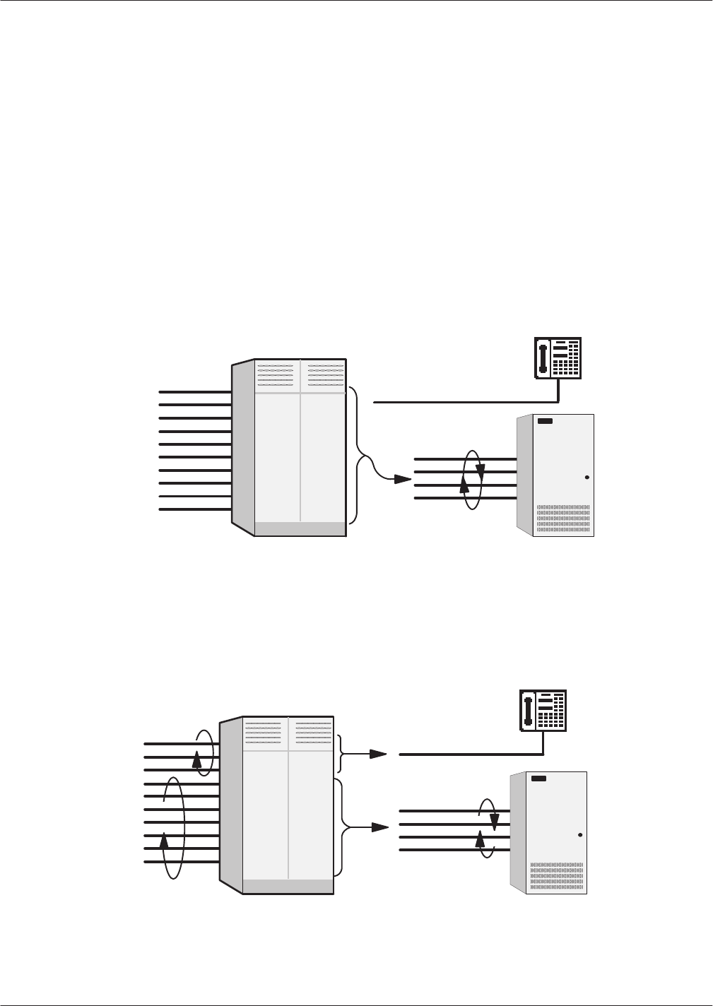
Preparing
the Phone System 3-3
Octel Overture 200/300 Serenade 3.0
PB60014–01
Answering Incoming Calls
The
Octel Overture 200/300 can answer all or a portion of a company’
s incoming calls. Through the PBX
programming, trunks can be directed to the Octel Overture 200/300 hunt group instead of the operator
through a PBX feature. This feature, often called DIL (Direct In Lines), allows trunks to be directed to a
specific extension or hunt group instead of the console.
The PBX may be set up to direct all or only some incoming trunks to the Octel Overture 200/300. For
example, the main company number may be answered by the attendant, while a second trunk group, with
a dif
ferent listed directory number
, can be directed to the Octel Overture 200/300. Ports answering
incoming calls are configured in AX mode.
Figure 3-2 is a block diagram of the Octel Overture 200/300 connected to the phone system where all
incoming lines are directed to it. Arrows denote hunting.
Figure 3-2
All Incoming Lines Directed to the Octel Overture 200/300
PBX Octel
Overture
200/300
Figure 3-3
is a block diagram of the Octel Overture 200/300 connected to a phone system that has
incoming lines split between the console and the Octel Overture 200/300. Arrows denote hunting.
Figure 3-3 Incoming Calls Split Between Console and the
Octel Overture 200/300
PBX Octel
Overture
200/300

3-4
Installation and Maintenance
Volume
Octel Overture 200/300 Serenade 3.0
PB60014–01
Acting
as a Message Center
The
Octel Overture 200/300 can also be set up to answer forwarded calls and act as a message center
. For
example, a company with a service provider
Centrex service already has a means of getting calls directly
to an extension. When the extension is busy or does not answer
, the extension can be forwarded to an
Octel Overture 200/300 hunt group to take a message. Ports receiving forwarded calls are configured in
CX mode. The Octel Overture 200/300 does not attempt to call the extension number entered by the
caller but immediately goes to that extension’s mailbox and of
fers to take a message.
The attendant may also extend callers to a port to allow them to leave a voice message. This port is
configured as MX mode. As with CX mode, it does not call the extension number entered but goes to that
extension’
s mailbox and of
fers to take a message.
Using the DID/E&M T
runk Interface
DID
and E&M trunks are wired through the DID/E&M Trunk Interface so that it can monitor the
progress of those calls. If appropriate, the interface diverts the call to the Octel Overture 200/300 for call
coverage. The DID/E&M T
runk Interface and the Octel Overture 200/300 communicate via an RS-232C
serial link. Ports receiving calls from the DID/E&M T
runk Interface can be in any mode. The Octel
Overture 200/300 handles the call based upon information sent by the DID/E&M T
runk Interface module.
Refer to the
DID/E&M T
runk Interface Installation and Maintenance
manual
for more information about
how the DID/E&M T
runk Interface works.

Preparing
the Phone System 3-5
Octel Overture 200/300 Serenade 3.0
PB60014–01
3.2 DETERMINING
NECESSAR
Y CHANGES
Octel
suggests that you perform a survey of the existing phone system during the initial phase of the
implementation process. From the descriptions of the application(s), decisions are made about how the
Octel Overture 200/300 should be used. Refer to the
Pr
oduct Description
volume, Implementation
chapter
, for a list of questions to ask during the survey
.
Use the results of the survey and the type of application to determine the necessary changes. Schedule
and track these changes using the checklist found in the Installation chapter
, Testing
the Installation and
T
elephone Changes section.
For convenience, Public Exchange (PE) trunk changes are separate from PBX changes. The following
sections discuss changes that may be required and guidelines for ordering the changes for both PE
trunking and the PBX.

3-6
Installation and Maintenance
Volume
Octel Overture 200/300 Serenade 3.0
PB60014–01
3.3 CHANGES
T
O CENTRAL OFFICE TRUNKING
Public
Exchange (PE) changes may be needed to
Add trunking capability
.
Change the order of trunk hunting.
Create new trunk hunting groups.
Add, change, or delete 800 services.
Add, change, or delete DID or Centrex services.
Split the hunt group (directory listed number), allowing some trunks to be directed to the console and
some to Octel Overture 200/300.
Additional Trunking
The
specific number of PBX lines and trunks depends on the number of ports and the desired trunking
arrangement.
Although the Octel Overture 200/300 port drops off after it transfers a call, the PE trunk is still occupied
during the entire call. When you decide how many trunks to direct to the Octel Overture 200/300,
remember each trunk is occupied from the time the call is placed until the caller hangs up. As a result,
the Octel Overture 200/300 can answer incoming calls from more trunks than it has ports.
Determine how many trunks to direct to the Octel Overture 200/300 by using PBX traf
fic data and the
traf
fic engineering tables. The tables are designed to help decide how to use the Octel Overture 200/300
most ef
fectively for a given situation. After collecting the traf
fic data, it may be necessary to order
changes from the telephone company to add or alter the number of trunks.
Splitting Trunk Groups
If
one two-way trunk group will be separated into two or more groups, the rotary hunting of the trunks
must be changed.
The Octel Overture 200/300 handles only incoming calls. If the trunks that the Octel Overture 200/300
answers are two-way trunks (also used for outgoing calls), make sure that suf
ficient trunks are available for
both incoming and outgoing calls. Additional trunks or changes to the type of trunks may be advisable. For
information on Direct Access Cards, refer to the
Dir
ect Access Car
d (DAC) Refer
ence Manual.
DID Trunks: Using the DID/E&M T
runk Interface
The
DID/E&M T
runk Interface monitors and intercepts DID/E&M calls. These trunks
do not
get
directed, via the DIL feature, to the Octel Overture 200/300 hunt group.
DID/E&M trunks using the DID/E&M T
runk Interface must be rewired to route through the DID/E&M
T
runk Interface module. Coordinate the installation with PE personnel to prevent the PE from busying out
the trunks. No changes are necessary to the DID trunk equipment or DID programming in the PBX. Refer
to the
DID/E&M T
runk Interface Installation and Maintenance
manual for more detailed information.

Preparing
the Phone System 3-7
Octel Overture 200/300 Serenade 3.0
PB60014–01
Ordering PE Trunking Changes
Contact
the customer about making arrangements for changes in trunking. T
ypically
, these changes
require significant lead time. The PE requires an agency letter from the customer authorizing you to act
on their behalf.
Figure 3-4 is a sample agency letter you may want to use.
Figure 3-4
Sample Agency Letter for PE Changes
On
this date we have entered into a contractual agreement with
(the
Octel Overtur
e 200/300
supplier)
to be our communications
representative relating to all voice grade telecommunication needs. This
agreement is for an indefinite period.
(The Octel Overtur
e 200/300
supplier)
may order connection and
disconnection of telephone-company provided services and equipment.
W
e hereby acknowledge that
(the Octel Overtur
e 200/300
supplier)
may obligate us for installation and other char
ges that may appear on
our telephone bill.
This authorization does not preclude our ability to act on our own
behalf as necessary
.
Please contact
(contact name) of
(the Octel Overtur
e 200/300
supplier)
at (
addr
ess, phone number
, and extension)
if you have any
questions.
(Customer’
s Name)
(TITLE)
(COMPANY)
DATE:
All concerned operating telephone companies and other
common carriers
ATTENTION:
Supervisor
TO:

3-8
Installation and Maintenance
Volume
Octel Overture 200/300 Serenade 3.0
PB60014–01
3.4 PHONE
SYSTEM CONFIGURA
TION
Changes
may be required to the following:
The Octel Overture 200/300 port extensions
Called extensions
Trunks
Redirection
Selection
Additional equipment may be required before these changes can be made. Most changes are to the PBX
database.
Port Extensions
Connect
and configure the port extensions using the following steps:
1.
Designate one touchtone, single-line, touchtone extension for each Octel Overture 200/300 port.
Additional PBX line circuits may be required.
2. T
erminate each of these extensions to a 66M connector block, or equivalent. Clearly mark each
termination point with the extension number
.
3.
Assign a PBX class of service to these extensions permitting them to
Initiate calls
Receive (incoming) calls
Place calls on hold
T
ransfer calls
Forward calls
4.
Remove any type of call waiting features from the Octel Overture 200/300 port extensions.
If configuring ports for outcalling to network locations for of
f-site message notification or for
of
f-site alarm calls, make sure the port extensions are
not r
estricted
from making calls to
these locations (e.g., toll restriction).
System speed dial commonly can override toll restriction. For security reasons, it may be
desirable to toll restrict the Octel Overture 200/300 ports to local calls and have the ports use
the PBX system speed dial for long distance outcalls.
5.
Set up a hunt group for each group of port extensions configured to answer in the same way
(company greeting, intercept position, mode). Where possible, make these circular hunt groups.
In cases where the PBX queues calls to a busy hunt group and no overflow position can be
defined, you may want to set up a “terminal” hunt group with the attendant, if possible, or
other PBX intercept position as the last member of the hunt. When all the ports are busy
, calls
hunt to this last member of the group for answer
.

Preparing
the Phone System 3-9
Octel Overture 200/300 Serenade 3.0
PB60014–01
6. Record
the pilot number for each hunt group. Depending on the PBX type, the pilot number may be
either
A phantom number with no actual extension appearance
The first extension of the hunt group
7.
Make the hunt group number easy to enter and easy to remember
, since employees use this number
to access the Octel Overture 200/300. Some phone systems permit single-digit access to hunt groups.
For example, employees need only press
to reach the Octel Overture 200/300.
8.
Determine how to set up a fail-safe answering position based upon features available for the PBX
type. This may be either programmed in the PBX as an overflow situation or by call forwarding the
hunt group pilot or member extensions. If none of these are permitted, refer to item 5 (above).
When the DID/E&M T
runk Interface sends calls to the Octel Overture 200/300 hunt group,
this group should not forward when busy
. The DID/E&M T
runk Interface directs the calls to
the Octel Overture 200/300. If the DID/E&M T
runk Interface receives a busy signal from the
Octel Overture 200/300, it redirects the call to the extension configured as the attendant. If the
group should overflow for non-DID/E&M T
runk Interface calls, this may require two hunt
groups with the same members, one of which overflows and another that does not. (Setting up
two hunt groups with the same members is not possible on all PBXs.)
Called
Extensions
Because
the Octel Overture 200/300 provides call coverage for busy extensions, any type of call waiting
*
feature provided by the PBX is not required. Remove this feature from the PBX configuration for
extensions called through the Octel Overture 200/300. PBX call waiting can mislead the second caller
,
who hears that the extension doesn’t answer instead of hearing the true busy status.
Remove any system call forwarding for call coverage (to a message center
, etc.).
Trunks
Possible changes to the PBX trunk programming include redirecting trunks to the Octel Overture 200/300
and assuring any trunking changes do not affect the selection of trunks for outgoing calls. No changes
need to be made to the DID trunking or programming in the PBX.
Trunk Redirection
Trunks
are directed to the Octel Overture 200/300 via a PBX feature. Many PBX manufacturers call this
feature DIL, Direct In Lines, or DIT, Direct In T
runks. T
able 3-1 lists several PBX manufacturers and the
name of that feature for their phone systems. If the phone system does not provide a DIL-type feature,
refer to the Implementing PBXs Without DIL Feature section in this chapter
.
*When a busy extension receives a second call, notification of the second call is given by a tone that indicates a call is waiting. The busy extension may
ignore the tone or place the first call on hold to answer the second. The notification tone is only heard by the called person and the caller hears ringing
instead of a busy tone.

3-10
Installation and Maintenance
Volume
Octel Overture 200/300 Serenade 3.0
PB60014–01
Table 3-1
PBX Features to Direct T
runks to the Octel Overture 200/300
PBX Manufacturer and Model
Name of Feature
AT&T
All
but Horizon and A
T&T System 25
DDC (Direct Department Calling)
Horizon and A
T&T System 25
DGC (Direct Group Calling)
ROLM DEDICATED
FUJITSU/American T
elecom Focus
QUASI-DID
NOR
THERN TELECOM SL-1
AUTO-TERMINATE
If the phone system you are working with is not mentioned here, and you are trying to determine the
appropriate feature, first look for DIL, the most commonly used name.
If you can talk with someone familiar with the phone system, describe the feature (i.e., “ability to direct a
trunk or group of trunks to a specific extension or hunt group rather than being directed to an attendant
console for answer”). They should be able to supply the name of the feature for that phone system.
The DID/E&M T
runk Interface unit monitors and intercepts DID calls. Consequently
, these trunks are
not
directed by the DIL feature to the hunt group.
Trunk Selection
With
some phone systems, incoming calls hunt from the beginning of a trunk group (trunk 1, trunk 2,...)
for an available trunk, while outgoing calls hunt in reverse order (trunk 10, trunk 9, ...). Others specify
the first and second preference trunk groups for both incoming and outgoing calls. If a lar
ge two way
trunk group is to be split, reexamine the PBX programming for outgoing trunk selection and determine
the trunk group to use for outgoing calls.
Ordering Phone System Changes
If
your company is not the PBX provider, order changes from the PBX vendor on behalf of the customer
.
Provide a Service Provider Letter (Figure 3-5) to the PBX vendor indicating the changes needed to the
PBX for the Octel Overture 200/300, and schedule the changes. If possible, try to use that PBX’
s
terminology when requesting these changes. Y
ou may also want to provide them with information from
this chapter
. Review the previous sections of this chapter for information to fill in the blanks. Read over
the letter and in particular
, the footnotes. Depending upon the application, portions of the letter may need
to be expanded upon or deleted.

Preparing
the Phone System 3-1
1
Octel Overture 200/300 Serenade 3.0
PB60014–01
Figure 3-5
Service Provider Letter
Dear
(
PBX-Vendor Name):
This letter confirms the service order and tentative installation of the Overture 200/300
for our mutual customer
, (
company name
).
The following items are pertinent to this order:
1. Extension changes. These changes need to be completed by (date). The
(manufacturer
e/model type switch
) is to be configured as follows:
a. Terminate (number) single-line extension on (number) in the telephone
equipment room. Be sure the customer has enough spare ports on extension
card(s) to support these. Please label these jacks with the assigned
extension numbers.
b. The single-line extensions are to have the following class of service
features:
Extensions
must be able to initiate, receive, transfer
,
and forward calls.
No call waiting feautres associated with any
extensions.
No toll restrictions on (
all/specified
) extensions.
c. The single-line extensions should be placed in a circular hunt group. Please
make the pilot number easy to enter and remember.
d. In the event all members of the hunt group are busy, subsequent calls
should be forwarded to (
PBX console attendant/defined extension
).
Define the last hunt number as an overflow extension.
1. Trunk
redirection. The following (or attached) list of
trunks needs to be directed via the (
name of DIL featur
e)
of the (
manufactur
er name
) PBX to the hunt group pilot
number
.
Cut-over of these trunks to the Overture 200/300 is scheduled to begin (time am/pm) on
(date). Any programming of the (name of the DIL feautre) must be ready by then.
Thank you for your cooperation. If you have any questions, please feel free to call me
at (
phone number and extension
).
Sincerely,
(NAME)
(TITLE)
The
vendor may require your Overture 200/300 registration
information:
FCC Registration
Ringer Equivalence 0.7A
PBX Interface 25-pair cable
Line card meets FCC Part 68
The unit meets FCC Part 15, Class A
UL Registration UL1459
Or other location where the unit is
to be placed. Refer also to the envi
-
ronmental requirements in INSTAL-
LA
TION, Installation Requirements
in this manual.
If more than one hunt group is re
-
quired, specify the number of exten-
tions for each hunt group.
For example:
hunt group #1 = 6 extensions
hunt group #2 = 2 extensions.
This information may not be avail
-
able for all PBXs. If you want this
call forwarding, however
, be sure to
include the number if it’s available.
Where multiple trunk groups exist,
specify the trunks for each hunt
group:
For example:
Hunt group #1 Trunks:
555-3700
555-3701
555-3702
555-3703
Hunt group #2 1-800-337-1100
1-800-337-1101
T
ailor this section to the customer
’s
needs. If trunk cut-over is stag
-
gered, include schedule in this let
-
ter
. If a PBX rtepresentative needs
to be on-site for this cut-over
, ar
-
range a mutually convenient time
with the PBX vendor.
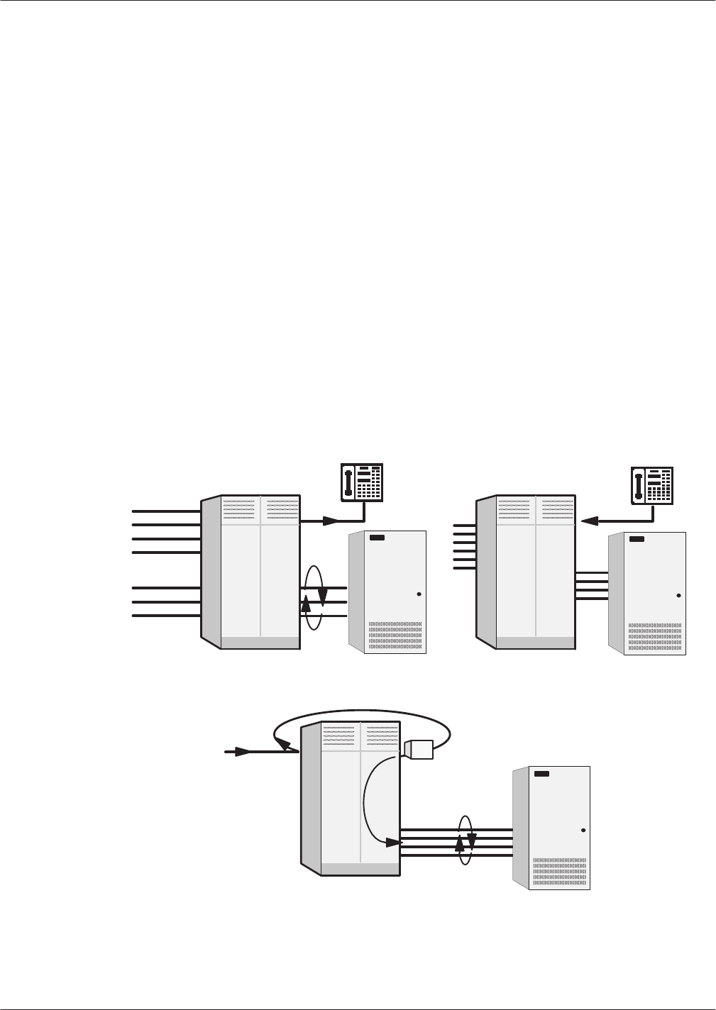
3-12
Installation and Maintenance
Volume
Octel Overture 200/300 Serenade 3.0
PB60014–01
3.5 IMPLEMENTING
THE OCTEL OVERTURE 200/300 ON PBXS
WITHOUT DIL FEA
TURE
You
may encounter a PBX with an older feature package that does not provide the DIL feature. The
PBXs most frequently encountered without DIL are AT&T Dimension PBXs with Feature Packages (FP)
2, 3, 4, 5, and 7.
This feature on the Dimension is called DDC for Direct Department Calling. It is only available in
FP 8, 10, 12, and 15.
If the customer
’
s Dimension does not have FP8 or later or it is a phone system that does not have a DIL
feature, there are several alternatives for directing trunks to the Octel Overture 200/300 ports for answer:
Upgrade the PBX to a feature package of
fering the DIL feature
Use DID numbers
Place the console in night mode
Use call diverters to switch calls to the Octel Overture 200/300 ports
Not all these alternatives may be feasible for a given situation. The following discusses each in detail.
For each incoming trunk
to be answered by the
Octel Overture 200/300.
Figure 3-6
Directing Incoming Calls to the Octel Overture 200/300
When the PBX Does Not Offer a DIL Feature
Main #
ĆXXXX
Call Diverter Ċ Programmed to call
the Octel Overture 200/300 hunt group.
Alternative
2 — Night Mode
Alternative 3 — Call Diverter
Alternative 1 — DID
DID
XXXĆXXXX
DID
Trunks
PBXPBX
PBX
Octel
Overture
200/300
Octel
Overture
200/300
Octel
Overture
200/300

Preparing
the Phone System 3-13
Octel Overture 200/300 Serenade 3.0
PB60014–01
Upgrade
the PBX to a Feature Package Offering the DIL Feature
Depending
on the customer
’
s current version, this may not be economically feasible. This is the most
straightforward solution, but possibly not the most practical.
Use DID Numbers
Some
customers may already have a block of DID numbers but do not wish to pay for DID numbers and
trunks for all employees. Callers may be given a number that is a DID extension answered by the Octel
Overture 200/300. This is especially suitable where a second number (not the main company number) is
to be established for company employees, friends, family
, and frequent callers to call to reach extensions
or receive information. Refer to Figure 3-6.
Again, in this way the Octel Overture 200/300 can answer a DID number. However, 800 service or main
company numbers cannot be answered this way
. Due to the cost of installing DID, this may only be
attractive to companies that already have DID.
Place the Console in Night Mode
If
the PBX does not have the DIL feature, placing the console in night mode usually may be used to
direct all
incoming trunks to a certain extension (such as the Octel Overture 200/300 hunt group). Refer
to Figure 3-6. However
, once the console has been placed in night mode, it may not be used. Callers
requiring assistance (through the Octel Overture 200/300) to a multibutton key set for answering. This
solution is most practical for
Smaller companies having a single console and willing to direct all trunks to the Octel Overture
200/300.
Companies using only Octel Overture 200/300 to answer after hours and on weekends.
Since the console cannot be used, callers who are toll restricted cannot get an outside line from the
operator.
Arrange
for T
runks to Call Divert to the Octel Overture 200/300
Ports
When
only some trunks are to be answered by the Octel Overture 200/300 (ruling out console Night
Mode), these trunks can be removed from the PBX and terminated on call diverters that are connected to
PBX extensions. Refer to Figure 3-6. These call diverters are programmed to call the Octel Overture
200/300 hunt group. The call diverter answers the trunk and calls (through the PBX) the hunt group
number
. The appropriate number of ports, as well as one additional extension per trunk to be diverted to
the Octel Overture 200/300,
are required.
The call diverter that operates satisfactorily in this situation is the BUSCOM 2008-RD manufactured by
MetroT
el. Because this diverter ordinarily allows remote turn-of
f by pressing a
key,
it requires a
modification.

Octel
Overture 200/300 Serenade 3.0
PB60014–01
4
INSTALLATION
4.1 Receiving
the Equipment
4-1.
. . . . . . . . . . . . . . . . . . . . . . . . . . . . . . . . . . . . . . . . . . . . . . . . . . . . . . . . . . . . . . . . . . . .
Inspecting
for Shipping Damage
4-1.
. . . . . . . . . . . . . . . . . . . . . . . . . . . . . . . . . . . . . . . . . . . . . . . . . . . . . . . . . .
Unpacking
the Cabinet
4-1.
. . . . . . . . . . . . . . . . . . . . . . . . . . . . . . . . . . . . . . . . . . . . . . . . . . . . . . . . . . . . . . . . . .
Reshipping 4-2
. . . . . . . . . . . . . . . . . . . . . . . . . . . . . . . . . . . . . . . . . . . . . . . . . . . . . . . . . . . . . . . . . . . . . . . . . . . . .
Moving
the Equipment On-Site
4-3.
. . . . . . . . . . . . . . . . . . . . . . . . . . . . . . . . . . . . . . . . . . . . . . . . . . . . . . . . . . .
4.2 Installation
Requirements
4-4.
. . . . . . . . . . . . . . . . . . . . . . . . . . . . . . . . . . . . . . . . . . . . . . . . . . . . . . . . . . . . . . . . . . . .
Site
Requirements
4-4.
. . . . . . . . . . . . . . . . . . . . . . . . . . . . . . . . . . . . . . . . . . . . . . . . . . . . . . . . . . . . . . . . . . . . . .
Power
Requirements
4-4.
. . . . . . . . . . . . . . . . . . . . . . . . . . . . . . . . . . . . . . . . . . . . . . . . . . . . . . . . . . . . . . . . . . . .
Isolation
T
ransformer 4-9.
. . . . . . . . . . . . . . . . . . . . . . . . . . . . . . . . . . . . . . . . . . . . . . . . . . . . . . . . . . . . . . . . . . .
Uninterruptible
Power Supply
4-10.
. . . . . . . . . . . . . . . . . . . . . . . . . . . . . . . . . . . . . . . . . . . . . . . . . . . . . . . . . . .
Installing
the Octel Overture 200/300 With –48-Vdc Power Supply Unit
4-10.
. . . . . . . . . . . . . . . . . . . . . . . .
Cabinet
Requirements
4-14.
. . . . . . . . . . . . . . . . . . . . . . . . . . . . . . . . . . . . . . . . . . . . . . . . . . . . . . . . . . . . . . . . .
Distributor-Supplied
Equipment
4-14.
. . . . . . . . . . . . . . . . . . . . . . . . . . . . . . . . . . . . . . . . . . . . . . . . . . . . . . . . . .
4.3 PBX
Preparation
4-15.
. . . . . . . . . . . . . . . . . . . . . . . . . . . . . . . . . . . . . . . . . . . . . . . . . . . . . . . . . . . . . . . . . . . . . . . . . .
4.4 Terminal
Communications
4-16.
. . . . . . . . . . . . . . . . . . . . . . . . . . . . . . . . . . . . . . . . . . . . . . . . . . . . . . . . . . . . . . . . . .
Terminal/Teleprinter
Installation
4-16.
. . . . . . . . . . . . . . . . . . . . . . . . . . . . . . . . . . . . . . . . . . . . . . . . . . . . . . . . . .
Compatible
T
erminals 4-16.
. . . . . . . . . . . . . . . . . . . . . . . . . . . . . . . . . . . . . . . . . . . . . . . . . . . . . . . . . . . . . . . . . .
Cable
Connections Between the RS-232C T
erminal and the Octel Overture 200/300
4-16.
. . . . . . . . . . . .
Connections
Between an External Modem and the Octel Overture 200/300
4-17.
. . . . . . . . . . . . . . . . . . . .
Connecting
to the Internal Modem
4-19.
. . . . . . . . . . . . . . . . . . . . . . . . . . . . . . . . . . . . . . . . . . . . . . . . . . . . . . .
4.5 Pin Assignments for Message Server Cards and Ports 4-21.
. . . . . . . . . . . . . . . . . . . . . . . . . . . . . . . . . . . . . . . . . .
Four-Port
Line-Interface Card, ROLM Integration Card, and Mitel Integration Card
4-22.
. . . . . . . . . . . . . .
Eight-Port
Line-Interface Card and T
elemarketing Line Card
4-23.
. . . . . . . . . . . . . . . . . . . . . . . . . . . . . . . . .
16-Port
Line-Interface Card (DLC16) and the PBX Integration Cards for
Northern T
elecom (NPIC) 4-24.
. . . . . . . . . . . . . . . . . . . . . . . . . . . . . . . . . . . . . . . . . . . . . . . . . . . . . . . . . . . .
12-Port
International Line-Interface Card
4-25.
. . . . . . . . . . . . . . . . . . . . . . . . . . . . . . . . . . . . . . . . . . . . . . . . . .
DTIC
Pin Assignment
4-26.
. . . . . . . . . . . . . . . . . . . . . . . . . . . . . . . . . . . . . . . . . . . . . . . . . . . . . . . . . . . . . . . . . .
Northern
T
elecom SL-1 Integration Card
4-27.
. . . . . . . . . . . . . . . . . . . . . . . . . . . . . . . . . . . . . . . . . . . . . . . . . .
AT&T
Integration Card (A
TTIC) 4-28.
. . . . . . . . . . . . . . . . . . . . . . . . . . . . . . . . . . . . . . . . . . . . . . . . . . . . . . . . . .
Serial
Integration Card for the Meridian 1 (SIC8)
4-29.
. . . . . . . . . . . . . . . . . . . . . . . . . . . . . . . . . . . . . . . . . . .
APIC
Integration Card
4-30.
. . . . . . . . . . . . . . . . . . . . . . . . . . . . . . . . . . . . . . . . . . . . . . . . . . . . . . . . . . . . . . . . .
SIC8
I/O Panel Pinouts
4-31.
. . . . . . . . . . . . . . . . . . . . . . . . . . . . . . . . . . . . . . . . . . . . . . . . . . . . . . . . . . . . . . . . .
Direct-Access Card (DAC) 4-32.
. . . . . . . . . . . . . . . . . . . . . . . . . . . . . . . . . . . . . . . . . . . . . . . . . . . . . . . . . . . . . .
Direct-Access
Card I/O Panel DP EXT Connector
4-33.
. . . . . . . . . . . . . . . . . . . . . . . . . . . . . . . . . . . . . . . . . .
Direct-Access
Card I/O Panel Power Connector
4-33.
. . . . . . . . . . . . . . . . . . . . . . . . . . . . . . . . . . . . . . . . . . .
External
Alarm Port
4-34.
. . . . . . . . . . . . . . . . . . . . . . . . . . . . . . . . . . . . . . . . . . . . . . . . . . . . . . . . . . . . . . . . . . . .
4.6 Communicating
with the Message server
4-35.
. . . . . . . . . . . . . . . . . . . . . . . . . . . . . . . . . . . . . . . . . . . . . . . . . . . . .
Local Access 4-35.
. . . . . . . . . . . . . . . . . . . . . . . . . . . . . . . . . . . . . . . . . . . . . . . . . . . . . . . . . . . . . . . . . . . . . . . . .
Remote Access 4-36.
. . . . . . . . . . . . . . . . . . . . . . . . . . . . . . . . . . . . . . . . . . . . . . . . . . . . . . . . . . . . . . . . . . . . . . .
Automatic
T
erminal Logout
4-36.
. . . . . . . . . . . . . . . . . . . . . . . . . . . . . . . . . . . . . . . . . . . . . . . . . . . . . . . . . . . . . .

Octel
Overture 200/300 Serenade 3.0
PB60014–01
4
INSTALLATION
(continued)
4.7 Octel
Overture 200/300 Hardware Installation
4-37.
. . . . . . . . . . . . . . . . . . . . . . . . . . . . . . . . . . . . . . . . . . . . . . . . .
Powering Up 4-37.
. . . . . . . . . . . . . . . . . . . . . . . . . . . . . . . . . . . . . . . . . . . . . . . . . . . . . . . . . . . . . . . . . . . . . . . . . .
Measuring d.c. Voltages 4-37.
. . . . . . . . . . . . . . . . . . . . . . . . . . . . . . . . . . . . . . . . . . . . . . . . . . . . . . . . . . . . . . . .
Connecting
the T
erminal 4-38.
. . . . . . . . . . . . . . . . . . . . . . . . . . . . . . . . . . . . . . . . . . . . . . . . . . . . . . . . . . . . . . . .
Starting
Up the System
4-38.
. . . . . . . . . . . . . . . . . . . . . . . . . . . . . . . . . . . . . . . . . . . . . . . . . . . . . . . . . . . . . . . . .
4.8 Rack
Mount Installation, Octel Overture 300
4-40.
. . . . . . . . . . . . . . . . . . . . . . . . . . . . . . . . . . . . . . . . . . . . . . . . . . .
Preinstallation 4-41
. . . . . . . . . . . . . . . . . . . . . . . . . . . . . . . . . . . . . . . . . . . . . . . . . . . . . . . . . . . . . . . . . . . . . . . . . .
Installation 4-41
. . . . . . . . . . . . . . . . . . . . . . . . . . . . . . . . . . . . . . . . . . . . . . . . . . . . . . . . . . . . . . . . . . . . . . . . . . . . .
Removal 4-42
. . . . . . . . . . . . . . . . . . . . . . . . . . . . . . . . . . . . . . . . . . . . . . . . . . . . . . . . . . . . . . . . . . . . . . . . . . . . . .
4.9 Software
Installation
4-44.
. . . . . . . . . . . . . . . . . . . . . . . . . . . . . . . . . . . . . . . . . . . . . . . . . . . . . . . . . . . . . . . . . . . . . . .
Using INST
ALL — Entering the Configuration Database
4-44.
. . . . . . . . . . . . . . . . . . . . . . . . . . . . . . . . . . . .
Using UPDATE 4-44.
. . . . . . . . . . . . . . . . . . . . . . . . . . . . . . . . . . . . . . . . . . . . . . . . . . . . . . . . . . . . . . . . . . . . . . . .
4.10 Connecting
the Phone System to the Octel Overture 200/300
4-45.
. . . . . . . . . . . . . . . . . . . . . . . . . . . . . . . . .
Connection Overview 4-45.
. . . . . . . . . . . . . . . . . . . . . . . . . . . . . . . . . . . . . . . . . . . . . . . . . . . . . . . . . . . . . . . . . .
Verifying
the Equipment
4-45.
. . . . . . . . . . . . . . . . . . . . . . . . . . . . . . . . . . . . . . . . . . . . . . . . . . . . . . . . . . . . . . . .
Connector Blocks 4-46.
. . . . . . . . . . . . . . . . . . . . . . . . . . . . . . . . . . . . . . . . . . . . . . . . . . . . . . . . . . . . . . . . . . . . . .
Wiring 4-47
. . . . . . . . . . . . . . . . . . . . . . . . . . . . . . . . . . . . . . . . . . . . . . . . . . . . . . . . . . . . . . . . . . . . . . . . . . . . . . . . .
4.11 Octel
Overture 200/300 T
esting 4-50.
. . . . . . . . . . . . . . . . . . . . . . . . . . . . . . . . . . . . . . . . . . . . . . . . . . . . . . . . . . . . . .
4.12 Testing
the Installation and T
elephone Changes
4-58.
. . . . . . . . . . . . . . . . . . . . . . . . . . . . . . . . . . . . . . . . . . . . . . .

Octel
Overture 200/300 Serenade 3.0
PB60014–01
4
INSTALLATION
4-1 Octel
Overture 200 Floor Plan for Installation in the US, Canada and Mexico
4-6.
. . . . . . . . . . . . . . . . . . . . . . .
4-2 Octel
Overture 300 Floor Plan for Installation for the US, Canada, and Mexico
4-7.
. . . . . . . . . . . . . . . . . . . . . .
4-3 Octel
Overture 200 Direct-Connect Installation
4-12.
. . . . . . . . . . . . . . . . . . . . . . . . . . . . . . . . . . . . . . . . . . . . . . . . .
4-4 Octel
Overture 300 Direct-Connect Installation
4-13.
. . . . . . . . . . . . . . . . . . . . . . . . . . . . . . . . . . . . . . . . . . . . . . . . .
4-5 Diagram
of the Field Wiring for –48-Vdc Powered Octel Overture 200
4-14.
. . . . . . . . . . . . . . . . . . . . . . . . . . . . .
4-6 First
and Second RS-232C Serial-Port Cable Pinouts for Connection to T
erminal Equipment (DTE)
4-17.
. . .
4-7 Octel
Overture 200/300 to External Modem Pinouts
4-18.
. . . . . . . . . . . . . . . . . . . . . . . . . . . . . . . . . . . . . . . . . . . .
4-8 50-Pin
Male T
elco Connector Pinouts
4-21.
. . . . . . . . . . . . . . . . . . . . . . . . . . . . . . . . . . . . . . . . . . . . . . . . . . . . . . . . .
4-9 Octel
Overture 200/300 Cabinet Installed in 19-Inch Rack
4-40.
. . . . . . . . . . . . . . . . . . . . . . . . . . . . . . . . . . . . . . .
4-10 Typical
Octel Overture 200/300 Connections
4-45.
. . . . . . . . . . . . . . . . . . . . . . . . . . . . . . . . . . . . . . . . . . . . . . . . . .
4-11 Connector Block 4-47.
. . . . . . . . . . . . . . . . . . . . . . . . . . . . . . . . . . . . . . . . . . . . . . . . . . . . . . . . . . . . . . . . . . . . . . . . . . .
4-12 Example of Server-to-Block Connections 4-48.
. . . . . . . . . . . . . . . . . . . . . . . . . . . . . . . . . . . . . . . . . . . . . . . . . . . . .
4-1 Input
Circuit Current at Nominal Operating Line V
oltage 4-5.
. . . . . . . . . . . . . . . . . . . . . . . . . . . . . . . . . . . . . . . . . .
4-2 Input
Power Requirements
4-9.
. . . . . . . . . . . . . . . . . . . . . . . . . . . . . . . . . . . . . . . . . . . . . . . . . . . . . . . . . . . . . . . . . . .
4-3 Equipment
Provided by Distributor
4-14.
. . . . . . . . . . . . . . . . . . . . . . . . . . . . . . . . . . . . . . . . . . . . . . . . . . . . . . . . . . .
4-4 DCE
Pinouts for Cable Connections Between the RS-232C T
erminal and the Octel Overture 200/300
4-17.
4-5 Pinouts
for External Modem Connections
4-18.
. . . . . . . . . . . . . . . . . . . . . . . . . . . . . . . . . . . . . . . . . . . . . . . . . . . . .
4-6 Power
Supply Output Rating and Acceptable Operating Ranges
4-38.
. . . . . . . . . . . . . . . . . . . . . . . . . . . . . . . . .
4-7 66M4-4W Connector Block Designators 4-49.
. . . . . . . . . . . . . . . . . . . . . . . . . . . . . . . . . . . . . . . . . . . . . . . . . . . . . .

Installation
4-1
Octel Overture 200/300 Serenade 3.0
PB60014–01
4.1 RECEIVING
THE EQUIPMENT
The
following paragraphs provide procedures for unpacking, inspecting, inventorying, and reshipping the
Octel Overture
200/300.
The server is shipped in the customer
-ordered configuration. All PCAs, power supplies, and disk drives
are installed in the cabinet. Depending on the options ordered with the server (such as W
orks for
Serenade or DAC), some additional assembly of the server might be required. Refer to specific sections
in this chapter about any options for assembly instructions. Each server is shipped on a pallet, protected
by foam inserts, and covered by a cardboard box.
W
eights at maximum configurations are as follows:
120 pounds (54 kg) for the Octel Overture 200
200 pounds (90 kg) for the Octel Overture 300
Inspecting for Shipping Damage
Before
accepting delivery of an
Octel Overture 200/300 from the carrier
, inspect the tilt-watch indicators,
located on the left front center and the right side center of the carton. Also inspect the cardboard carton.
If the tilt-watch is tripped or the carton has external damage, notify the carrier immediately
, and submit a
damage report to the carrier and to Octel Communications. In the event of equipment damage, negotiate
claims directly with the carrier
.
Unpacking
the Cabinet
Do
not take the server of
f the shipping pallet unless the unpacking is being done at the installation site.
Caution!
Make sure that you have at least two people to
remove the server from the pallet. Because of the
weight of the server
, it could be damaged or a person
could be injured.
1.
Remove the plastic clips securing the cardboard carton to the shipping pallet. Squeeze the center of
the clip, lift it, and pull it away from the carton.
2.
Remove the cardboard carton by lifting it straight up.
3.
Remove the foam insert from the top of the server
.
4.
Remove the bag from the top of the server
. The bag contains the front-door key
, power cord, and
message-server documents.
5.
Inspect the server visually for physical damage.
6.
Use a 7/16 inch wrench to remove the four brackets that secure the server to the pallet. The brackets
are located at the base of the server
.

4-2
Installation and Maintenance
Volume
Octel Overture 200/300 Serenade 3.0
PB60014–01
7. Unlock
and open the front door
. It is recommended that the front door be removed before moving the
cabinet from the pallet.
8.
Lift the cabinet straight up, until the stabilizer legs have cleared the server
. Lift the server off the
pallet toward the pallet opening at the front of the server
.
9.
Place the server in its permanent location.
10.
Replace the front door
.
11.
When the Octel Overture 200/300 is installed, adjust the levelers until the top of the server is level and
does not wobble. No special tools are required to adjust the leveling, although a bubble level is
recommended for this purpose.
12.
Collect and save all packing material, cartons, foam inserts, shipping pallet, etc., as they can be reused
to ship the server back to Octel if any shipping damage was incurred.
Reshipping
If
the Octel Overture 200/300 is to be reshipped from your location, use the original shipping carton, and
perform the following:
1. V
erify that all server assemblies are secure.
a.
All boards must be seated and secured with locking ejectors.
b.
All captive fasteners on the disk drive, power supply
, and fan assemblies must be secured to the
cabinet with a flat-blade screwdriver
.
2.
Remove cabinet front door by opening the door and pulling it straight up, until it is free of the two
hinges.
3.
Remove the front pallet section and place the server on the shipping pallet. This
must
be performed
by two people.
4.
Replace and lock the front door
.
5.
Resecure the front pallet section against the front door
, using two pallet bolts.
6.
Replace the plastic bag over the cabinet.
7.
Secure the cabinet to the pallet using new tie straps.
8.
Replace the door key and power supply cord in the documentation bag and tape the bag to the top of
the cabinet.
9.
Replace the foam insert, then the cardboard container
.
10. T
ape the top of the cardboard carton closed and secure it to the pallet with new strapping material.
Caution!
Do not transport the Octel Overture 200/300 message
server unless it is secured on the shipping pallet in
the vertical, upright position.

Installation
4-3
Octel Overture 200/300 Serenade 3.0
PB60014–01
Moving the Equipment On-Site
Before
moving the server
, verify the status of the new site:
Is the input power ready?
Is it the same as the input power required for the Octel Overture 200/300?
Is the installation location ready?
Are the telephone extensions ready to be hooked up?
Move the Octel Overture 200/300 server in the vertical, upright position on the shipping pallet. Be
careful and always remember that the Octel Overture 200/300 is delicate electronic equipment.

4-4
Installation and Maintenance
Volume
Octel Overture 200/300 Serenade 3.0
PB60014–01
4.2 INSTALLATION
REQUIREMENTS
Installing
the Octel Overture 200/300 involves the following:
Connecting PBX extensions to Octel Overture 200/300 ports
Connecting power to the cabinet
Installing the configuration database
Updating the database for both the Octel Overture 200/300 and the PBX
Dedicating trunks in the PBX to the Octel Overture 200/300 hunt or distribution group
Testing
Installation personnel should be familiar with the data format and change procedures of the PBX. For
further explanation, refer to the Preparing the Phone System chapter in this volume.
Site
Requirements
Install
the Octel Overture 200/300 in a dust-free location. Keep the Octel Overture 200/300 separate from
other equipment that might produce heat, generate strong magnetic fields, or produce vibration.
If space and environment permit, install the Octel Overture 200/300 in the telephone equipment room.
Place the cabinet to permit front access and ventilation on all sides. The air filter cleaning and
replacement schedule depends on the local environment.
Figure 4-1 is a floor plan for installing the Octel Overture 200 in the United States, Canada, and Mexico.
Figure 4-2 is a floor plan for installing the Octel Overture 300 in the United States, Canada, and Mexico.
Power
Requirements
The
Octel Overture 200/300 should receive power from a dedicated, separate circuit. If this is not
possible, make sure that the circuit is free of lar
ge motorized equipment, such as copy machines.
The power circuit must be compatible with the input voltage and frequency rating of the Octel Overture
200/300. The power circuit must have adequate current rating and be protected by a circuit breaker
.
Check the voltage rating marked on the power
-line filter where the power cord connects to the Octel
Overture 200/300. The voltage rating indicates the input current rating for the Octel Overture 200/300.
T
able 4-1 indicates the input circuit current that is to be supplied by a dedicated branch circuit.

Installation
4-5
Octel Overture 200/300 Serenade 3.0
PB60014–01
Table 4-1
Input Circuit Current at Nominal Operating Line V
oltage
Input Voltage
R
Frequency
R
Rated Input Current
pg
Range
qy
Range
Octel Overture
200
Octel Overture
300
120
V
ac
240 V
ac
–48 Vdc
50–60 Hz
50–60 Hz
dc
6 A
3 A
10 A
10 A
6 A
15 A
In the United States, the 120-V
ac wall sockets are rated at 10 amperes and use a NEMA 5–15P plug rated
for 15 amperes. Octel recommends the use of a standard a.c. branch circuit rated at 15 amperes to comply
with the normal United States wiring practices.
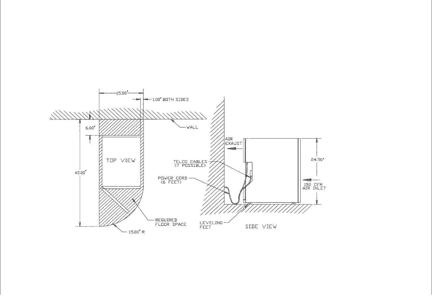
4-6
Installation and Maintenance
Volume
Octel Overture 200/300 Serenade 3.0
PB60014–01
Figure 4-1
Octel Overture 200 Floor Plan for Installation in the US, Canada and Mexico
#" %
#" %!
" "
"%$
Rear access for system cabling
Front access for service of field
Side access not required
Equipment room
Office environment
1706 BTU/hr
-
-
-
-
-
-
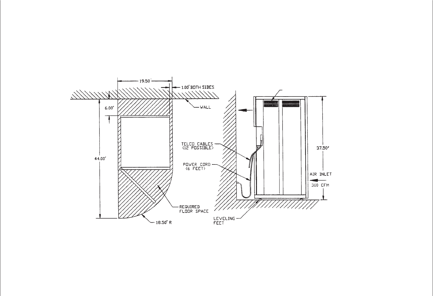
Installation
4-7
Octel Overture 200/300 Serenade 3.0
PB60014–01
Figure 4-2
Octel Overture 300 Floor Plan for Installation for the US, Canada, and Mexico
Rear access for system cabling
Front access for service of field
Side access not required
Equipment room
Office environment
3412 BTU/hr
-
-
-
-
-
-
$)#(&+%
$)#(&+'%
#(&#( $#!
&"##(!+* &

4-8
Installation and Maintenance
Volume
Octel Overture 200/300 Serenade 3.0
PB60014–01
IMPORTANT
SAFETY INSTRUCTIONS FOR A.C. POWERED SYSTEMS
SA
VE THESE INSTRUCTIONS
To
conform to the safety agency grounding requirements, use the power cord provided. This
power cord complies with the following UL requirement:
“An equipment grounding conductor that is not smaller in size than the ungrounded
branch-circuit supply conductors, is to be installed as part of the circuit that supplies the product
or system. Bare, covered or insulated grounding conductors are acceptable. Individually covered
or insulated equipment grounding conductors shall have a continuous outer finish that is either
green, or green with one or more yellow stripes. The equipment grounding conductor is to be
connected to ground at the service equipment.”
V
erify that the wall power outlet conforms to the following UL requirement:
“The attachment-plug receptacles in the vicinity of the product or system are all to be of a
grounding type, and the equipment grounding conductors serving these receptacles are to be
connected to earth ground at the service equipment.”
Refer to T
able 4-1 for the input-circuit current capacity that is to be supplied for a dedicated circuit.
Use the following guidelines for calculating the input power requirements of an
Octel Overture 200/300.
If the Octel Overture 200/300 is powered by an a.c. uninterruptible power supply (UPS) or a –48
Vdc
source, the input power requirement should be calculated to ensure that the correct-capacity power source
is chosen. The power requirements depend on the message server
’
s configuration, because a fully
populated cabinet requires more power than a minimally configured cabinet. The size of the a.c. UPS or
d.c. source must be chosen to match the maximum size configuration expected for each installation.
1.
Calculate the exact message-server configuration, including all known growth plans.
2.
Determine the total power consumption (in watts) of the configuration, using the values in T
able 4-2.
3.
If the message server is to be powered by an a.c. UPS, multiply the total power consumption figure
by 1.5 to determine its volt-ampere requirements.
4.
The total power consumption and volt-ampere requirements should be rounded up to the next
multiple of 50, before being used to choose an a.c. UPS or –48 Vdc source.

Installation
4-9
Octel Overture 200/300 Serenade 3.0
PB60014–01
Table 4-2
Input Power Requirements
Component
Power Consumption (watts)
Octel Overture 200 Octel Overture 300
Base
cabinet
125 150
4-port line card
10 10
8-port line card
15 15
16-port line card
15 15
Fax Application Processor
30 30
LAN card
20 20
V
oice/system disk drive
25 25
W
orks for Serenade
t
disk
20 20
EntryW
orks ACP card
20 20
.
The base cabinet includes VCU, CPU, floppy-disk drive, fans, and PSU. All voice/system disk
drives require the same amount of power
, regardless of their storage capacity
.
The following example for an
Octel Overture 300 message server shows the calculation of the input
power requirements for an 8-port message server, equipped with two 4-port line cards, one integration
card, and two voice/system disk drives:
Base cabinet
150 W
T
wo 4-port line cards
20 W
One integration card
10 W
T
wo voice/system disk drives
50 W
T
otal input power
230 W
T
otal volt-ampere rating (1.5 x 230)
345 VA
Round the total-input power value and the total volt-ampere rating up to the next multiple of 50,
producing the values to be used to select a suitable power source:
T
otal continuous input power requirement is 250 watts and 350 V
A
Isolation Transformer
For
installation sites that could experience power
-line transients from lightning or power switching, the
use of an isolation transformer is recommended. A dedicated isolation transformer must be rated at the
following:
-
750 V
A or greater is required for the Octel Overture 200.
-
1 kV
A or greater is required for the Octel Overture 300.
Contact Octel for isolation transformers that have been tested and qualified for use with Octel Overture
200/300.

4-10
Installation and Maintenance
Volume
Octel Overture 200/300 Serenade 3.0
PB60014–01
Uninterruptible Power Supply
If
an uninterruptible power supply (UPS) is used, depending on the configuration of the Octel Overture
200/300, a UPS must be rated up to the following:
750 V
A is required for the Octel Overture 200.
1 kW (1400 V
A) is required for the Octel Overture 300.
Contact Octel for a UPS that has been tested and qualified for use with the Octel Overture 200/300.
Installing
the Octel Overture 200/300 W
ith –48-Vdc Power Supply
Unit
The
–48-Vdc powered server does not include a power cord. A terminal block is provided on the back of
the cabinet for field wiring to the d.c. power source. The installation must be performed as described
below
, to comply with National Electrical Code (NEC) and UL regulations. In addition, use only those
materials mentioned, because they must also be controlled. Field-wiring material is not included with the
server
, but it can be obtained from a local hardware store or qualified electrician.
List of Materials
The
following materials are required for the installation:
1/2-inch diameter conduit.
UL-approved, insulated, stranded wire to run through the conduit. Three separate wires must be
connected; therefore, use three different wire colors. The grounding conductor insulation should be
green and yellow
.
The wire size for the Octel Overture 200 must be 12-gauge (3 mm
2).
The wire size for the Octel Overture 300 must be 10-gauge (5 mm
2).
The d.c. version of the Octel Overture 200/300 must be field-wired and connected to
a branch circuit equipped with a branch-circuit overcurrent-protection device, set at
the following:
20 A maximum, 60 Vdc for the Octel Overture 200.
25 A maximum, 60 Vdc for the Octel Overture 300.
The conduit and the UL-approved, insulated stranded wire can be obtained preassembled.
Six forked, crimp-on terminals with upturned ends for the wire size and a #10 screw
.
Conduit strain relief to fit a 1.10-inch-diameter hole in the sheet metal.

Installation
4-1
1
Octel Overture 200/300 Serenade 3.0
PB60014–01
Installation Procedure
Perform
the following steps to install the message server with a –48-Vdc power supply:
1.
Place the Octel Overture 200/300 near the –48-Vdc power source.
2. T
urn OFF the power to the d.c. power
-source outlet to which the Octel Overture 200/300 will be
connected.
3.
Open the front door of the cabinet and verify that the power switch on the Power Supply Unit is in
the OFF position.
4.
Remove the two screws attaching the cover to the d.c. filter assembly
, as shown in Figure 4-3 (Octel
Overture 200) or Figure 4-4 (Octel Overture 300) and remove the cover
.
5.
Connect the Octel Overture 200/300 to the power source as shown in Figure 4-3 or Figure 4-4 and
Figure 4-5. Connect the positive pole of the power source to the terminal-block position marked “+”
and the negative pole to the position marked “–”.
6.
Connect the earth-ground conductor from a suitable building ground to the ground stud next to the
terminal block on the cabinet (refer to Figure 4-3 or Figure 4-4 and Figure 4-5).
7.
Secure the cover to the d.c. filter assembly with the two screws removed in step 4.
8. T
urn ON the power to the d.c. power
-source outlet where the Octel Overture 200/300 has been
connected.
9. T
urn ON the power switch located on the power supply unit in the Octel Overture 200/300 cabinet, and
verify proper operation, as discussed in the Octel Overture 200/300 T
esting section in this chapter
.
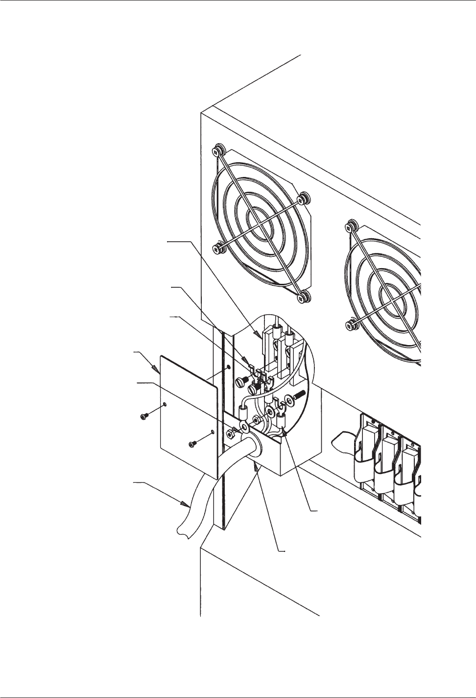
4-12
Installation and Maintenance
Volume
Octel Overture 200/300 Serenade 3.0
PB60014–01
Figure 4-3
Octel Overture 200 Direct-Connect Installation
Terminal Block
Negative Lead
Positive Lead
Cover Plate
Conduit Strain
Relief
12Ćinch Diameter
Conduit
DC Inlet Box
Ground
Lead
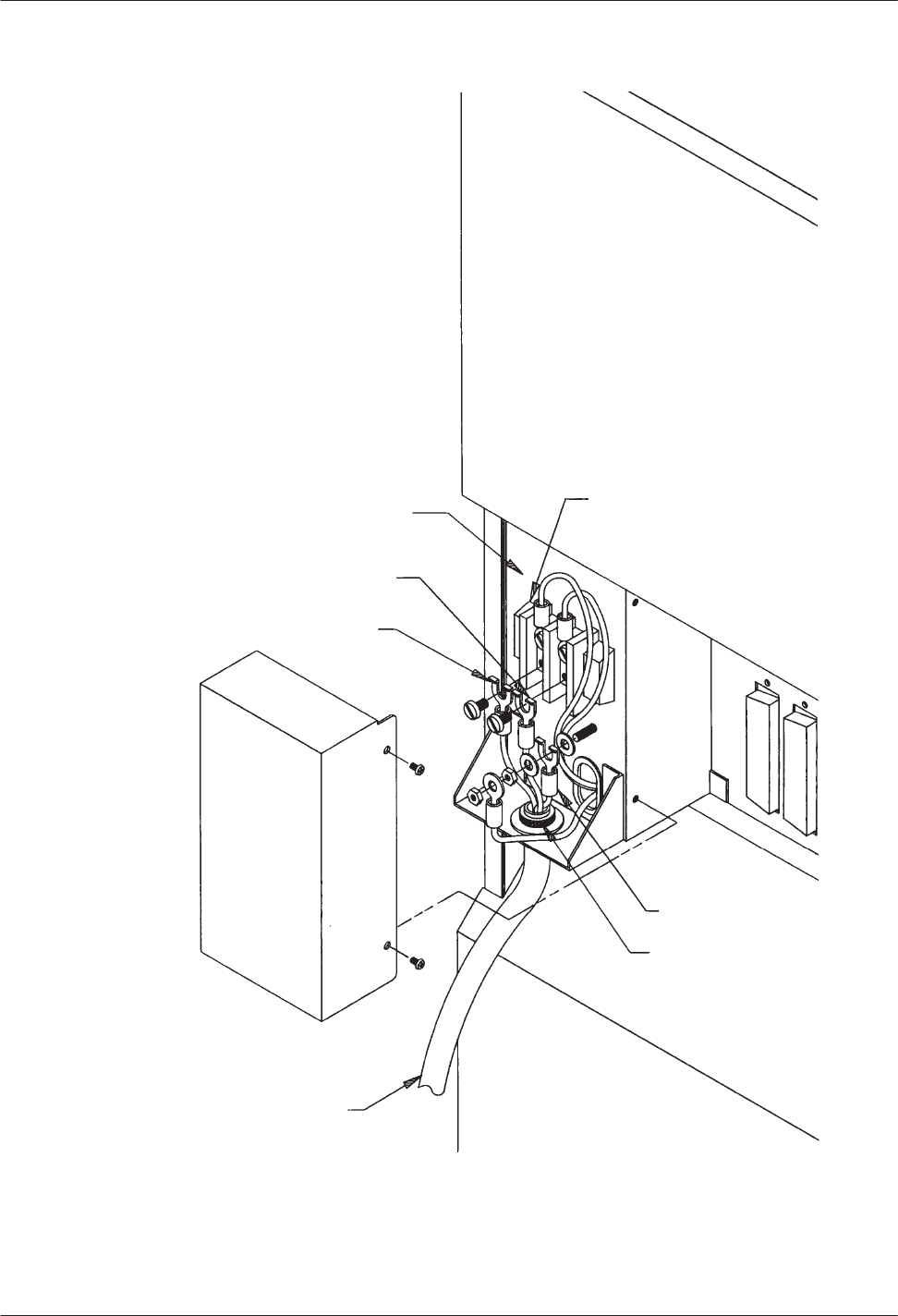
Installation
4-13
Octel Overture 200/300 Serenade 3.0
PB60014–01
Figure 4-4
Octel Overture 300 Direct-Connect Installation
DC Filter Assembly
Positive Lead
Negative Lead
Cover
Terminal Block
Ground Lead
Conduit Strain Relief
1/2Ćinch Diameter Conduit
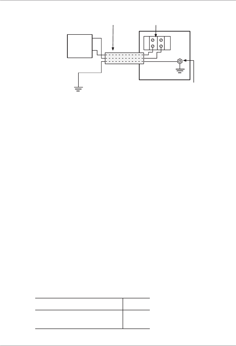
4-14
Installation and Maintenance
Volume
Octel Overture 200/300 Serenade 3.0
PB60014–01
Figure 4-5
Diagram of the Field Wiring for
–
48-Vdc Powered
Octel Overture 200
DC
Power
Source
Earth Ground
Conduit W
ith Three W
ires
Ground Stud
+
–
–
+
Rear Panel
T
erminal Block
Cabinet
Requirements
When
you install the Octel Overture 200/300, adjust the levelers until the top of the cabinet is level, and
the cabinet does not rock. A bubble level is recommended for this purpose. No special tools are required
to adjust the leveling feet.
Distributor-Supplied Equipment
Each
Octel Overture 200/300 line card is connected to the PBX with a 25-pair cable. Supply one cable
for each line card. Make sure that the male/female connectors are long enough to reach between the Octel
Overture 200/300 and the PBX extension jack, without undue stretching or tension.
The Octel Overture 200/300 can be connected to punchdown blocks with a 25-pair cable and then be
jumpered to the PBX or Central Of
fice lines. The Octel Overture 200/300 can also use 25-pair cable to
connect to a breakout adapter that provides standard modular connectors.
A terminal, used for software installation and update, must be available at the customer site. During
installation, use an RS-232C cable to connect the terminal to the Octel Overture 200/300. This terminal
can be connected to the SP1 connector located in the front of the cabinet or at J1 in the rear of the
cabinet. If the terminal is to be permanently installed with the message server
, connect it to J1. If the
terminal is only used temporarily during installation and maintenance, connect it to SP1. A printer is
useful for making a hard copy of the software configuration.
T
able 4-3 lists the equipment provided by the distributor
. Refer to the Octel Overture 200/300 T
esting
section in this chapter for additional equipment needed for testing.
Table 4-3
Equipment Provided by Distributor
Item Quantity
ASCII
terminal (CR
T or printer)
RS-232C cable for terminal or printer
1
1

Installation
4-15
Octel Overture 200/300 Serenade 3.0
PB60014–01
4.3 PBX
PREP
ARATION
Before
continuing with the installation, ensure that the appropriate PBX changes have been made and
tested. Instructions for preparing the PBX for the installation of the Octel Overture 200/300 are provided
in the Preparing the Phone System chapter of this manual. Refer to that chapter for the following:
Changing the PBX database
Setting up hunt groups
Directing trunks to the Octel Overture 200/300

4-16
Installation and Maintenance
Volume
Octel Overture 200/300 Serenade 3.0
PB60014–01
4.4 TERMINAL
COMMUNICA
TIONS
The
Octel Overture 200/300 is designed to work with any ASCII send/receive serial terminal/teleprinter
that meets RS-232C specifications.
Terminal/Teleprinter Installation
Octel
recommends that the maximum distance between the terminal and the Octel Overture 200/300 is no
more than 50 feet, which is the length of a standard RS-232C cable.
The Octel Overture 200/300 uses even parity, 7 data bits, 1 stop bit, and XON/XOFF protocol.
Compatible Terminals
The
following terminals can be connected to the Octel Overture 200/300:
TI Silent 700 or 703
Hazeltine Model 1410
Hewlett-Packard Models 2621A/P
, 2631A
Lear Siegler Model ADM-3A
W
yse Model WY
-50
TeleV
ideo T
erminal Model 950
Panasonic KXD-1
1
Falco 5500e, 500e
Configuration Applications Terminal (CA
T) (no procedures provided)
Connect the terminal/teleprinter to the system-terminal port. T
wo connections to the system-terminal port
allow for convenient access: the front connection (SP1) for temporary access and the rear connection (J1)
for permanent access. Octel recommends that the terminal/teleprinter have the capability to make a
hard-copy printout.
Cable
Connections Between the RS-232C T
erminal and the Octel
Overture 200/300
The
system-terminal port (SP1 or J1) and Port B (J2) use standard 25-pin (DB25) RS-232C connectors
(female), with the DCE pinouts listed in T
able 4-4. Figure 4-6 is a diagram of these pinouts. On the Octel
Overture 300, ports C and D (J3 and J4) are reserved for future use. They use the same pinouts as listed in
T
able 4-4 and shown in Figure 4-6.
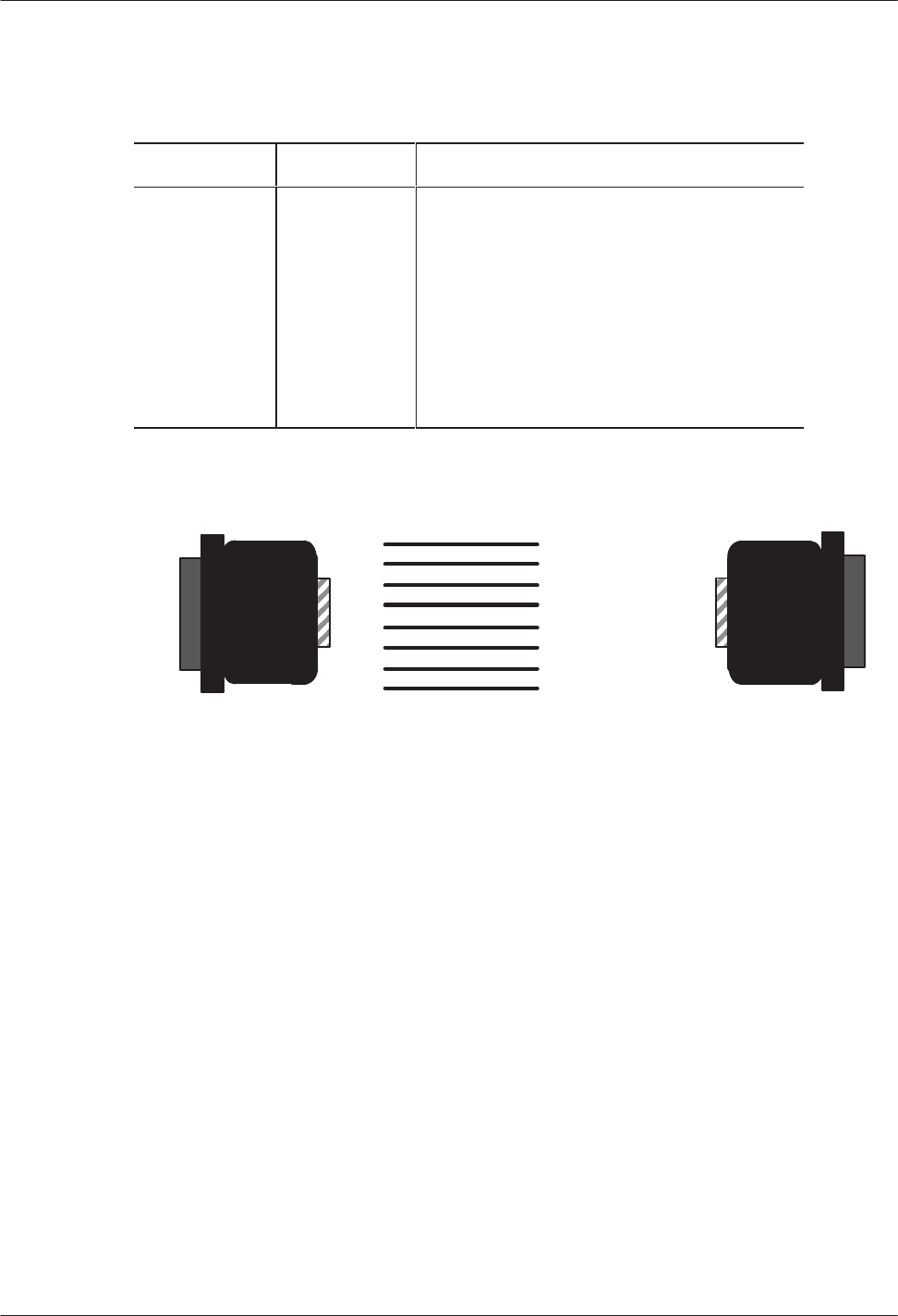
Installation
4-17
Octel Overture 200/300 Serenade 3.0
PB60014–01
Table 4-4
DCE Pinouts for Cable Connections Between the RS-232C
T
erminal and the Octel Overture 200/300
Pin EIA/CKT Signal Function
1
2
3
4
5
7
8
20
AA
BA
BB
CA
CB
AB
CF
CD
Protective
ground
T
ransmit data (TX)
Receive data (RX)
Request to send (R
TS)
Clear to send (CTS)
Signal ground
Receive-line signal detector (DCD)
Data terminal ready (DTR)
Figure 4-6
First and Second RS-232C Serial-Port Cable Pinouts
for Connection to T
erminal Equipment (DTE)
1
2
3
4
5
7
8
20
1 Protection Ground
2TX
3RX
4RTS
5 CTS
7 Signal Ground
8 DCD
20 DTR
Octel Overture
200/300 (DCE)
To Terminal (DTE)
For correct operation, DTR (pin 20) must be asserted TRUE by the terminal. R
TS (pin 4) must be exerted
TRUE by the terminal when the terminal is able to accept data, or pin 4 must be left open.
If the terminal/teleprinter equipment has
pins 1 and 7
connected together
,
intermittent pr
oblems
with
the Octel Overture 200/300 might occur
. T
erminal/teleprinters requiring Data Set Ready (DSR) could
require that pins 6 and 8 be connected together
, or pins 8 and 20 connected together at the terminal end of
the RS-232C cable. If you have a problem with or question about your terminal/teleprinter
, call Octel
technical support.
Connections
Between an External Modem and the Octel Overture
200/300
You
can use an external modem if a dedicated modem connection is required or if a modem with a baud
rate dif
ferent from the Octel Overture 200/300 internal modem is required. Y
ou can use a modem that
supports standard baud rates (300 to 9600 baud) connected to the system-terminal port. T
able 4-5 lists the
pinouts for an external modem connection. Figure 4-7 is a diagram of external modem pinouts.
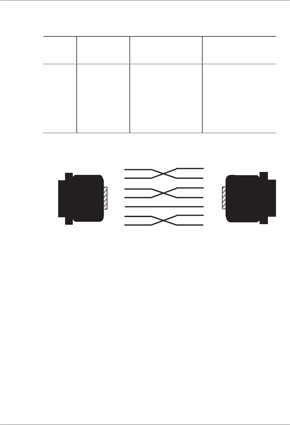
4-18
Installation and Maintenance
Volume
Octel Overture 200/300 Serenade 3.0
PB60014–01
Table 4-5
Pinouts for External Modem Connections
Modem
Pin
Number
Octel Overture
200/300
Pin Number
Modem Signal
Name/Function
Octel Overture 200/300
Name/Function
2
3
5
4
7
8
20
3
2
4
5
7
20
8
Transmit
data
Receive data
CTS
RTS
Signal ground
DCD
DTR
Receive data
T
ransmit data
RTS
CTS
Signal ground
DTR
DCD
Figure 4-7
Octel Overture 200/300 to External Modem Pinouts
RS-232C
Male Connectors
T
o modem
(DCE) T
o Octel Overture 200/300
(DCE)
The Octel Overture 200/300 requires pin 4 (R
TS) to be TRUE or left open and pin 20, Data T
erminal
Ready (DTR), to be TRUE. The modem must provide DCD (pin 8) and CTS (pin 5) at the modem
connector; that is, DTR (pin 20) and R
TS (pin 4) at the Octel Overture 200/300 connector
.
Other considerations are as follows:
The modem must drop DCD with the loss of carrier. If service is interrupted and the modem does not
drop DCD, subsequent callers can reestablish the connection without requiring a security code.
Auto-answer must be enabled to allow technical support personnel to connect to the modem without
on-site intervention.
Octel recommends forcing DTR high. This is required to maintain the connection with the message
server
, if a restart or reload is required. If DTR is not forced high, the connection is lost when the
message server is restarted.
Cable the modem to either the front or rear system-terminal port. T
est that the modem is correctly
configured. If you have a problem or question connecting your modem, call Octel technical support.
Installation
4-19
Octel Overture 200/300 Serenade 3.0
PB60014–01
Caution!
Incorrect
connection of the external modem can
result in unauthorized access. V
erify that the cabling
and modem are installed correctly
, and that the
modem setup is tested. Refer to the Octel Overture
200/300 Support Note FI80048-01 for additional
information.
Once the modem connection is established, press
until the password prompt appears, and follow
the procedures in the Communicating with the Message Server section of this chapter
.
Connecting to the Internal Modem
The
Octel Overture 200/300 has an internal 300/1200/2400-baud modem. The internal modem can be
connected either by entering
when the Octel Overture 200/300 answers or through a
modem-access mailbox.
Connecting to the Internal Modem Using
Connect
the message server to the internal modem, as follows:
1.
Call the Octel Overture 200/300.
2.
When the Octel Overture 200/300 answers, enter
.
3.
After you hear the high-pitched tone, enter the code to connect to the modem (A
TD). The code can
vary
, depending on the interface and modem manufacturer
. If you do not hear a high-pitched tone,
repeat steps 1 and 2.
4.
Hang up the receiver if step 3 was successful.
The Octel Overture 200/300 automatically adjusts to the modem’
s baud rate, which must be 300, 1200, or
2400 baud.
Modem-Access Mailboxes
To
provide additional system security
, access to the internal modem can be restricted to specific
modem-access mailboxes.
T
o create a modem-access mailbox, assign COS Attribute 1
18 — PROVIDE MODEM T
ONE WHEN
MAILBOX IS CALLED, and Attribute 3 — ASK FOR SECURITY CODE BEFORE CALLING
EXTENSION, to the mailbox COS. The mailbox should have a security code assigned before attribute 3
is added.
T
o use
to block access to a modem, set System Parameter 223 — DISABLE ###5 ACCESS
T
O THE MODEM, to YES.
After the modem-access mailbox is created, perform the following steps to connect to the internal modem
through the modem-access mailbox:
1.
Call the Octel Overture 200/300.
2.
When the company greeting plays, enter the mailbox number of the modem-access mailbox.

4-20
Installation and Maintenance
Volume
Octel Overture 200/300 Serenade 3.0
PB60014–01
3. If
attribute 3 is assigned to the mailbox COS, enter the security code.
4.
After the high-pitched tone, enter the code to connect to the modem (A
TD). The code can vary
,
depending on the interface and modem manufacturer
. If you do not hear a high-pitched tone, repeat
steps 1 through 3.
5.
Hang up the receiver if step 4 was successful.
The Octel Overture 200/300 automatically adjusts to the modem’
s baud rate, which must be 300, 1200, or
2400 baud.

Installation
4-21
Octel Overture 200/300 Serenade 3.0
PB60014–01
4.5 PIN
ASSIGNMENTS FOR MESSAGE SER
VER CARDS AND
PORTS
Connectors
P1 through P12 use a 50-pin male telco connector with the pin arrangement shown in
Figure 4-8.
Figure 4-8
50-Pin Male T
elco Connector Pinouts
The
following sections contain tables showing the pin assignments for the following:
Line-interface card (LIC4, LIC8, DLC16, and ILC12)
Digital trunk interface card (DTIC)
T
elemarketing line card (TLC)
ROLM integration card (RIC)
Northern T
elecom SL-1 integration card (SLIC)
A
T&T integration card (A
TTIC)
Mitel integration card (MIC)
Serial integration card for the Meridian 1 (SIC8)
A
T&T PBX integration card (APIC)
Northern T
elecom PBX integration card (NPIC)
Direct-access card (DAC)
Direct-access card I/O panel J5 connector
Direct-access card I/O panel power connector (P8)
External-alarm port (J3 for Octel Overture 200 and J5 for Octel Overture 300)

4-22
Installation and Maintenance
Volume
Octel Overture 200/300 Serenade 3.0
PB60014–01
Four-Port Line-Interface Card, ROLM Integration Card, and
Mitel Integration Card
The
following pin assignments are for the four
-port line-interface card (LIC4), the ROLM integration
card (RIC), and the Mitel integration card (MIC), as they appear on the rear 50-pin telco connector
. If an
LIC is installed in slot A1, it uses 50-pin telco connector P1; if it is installed in slot A2, it uses connector
P2, etc.
50-Pin
Number
Signal Function
50-Pin Number
Signal Function
1 RING1 26 TIP1
2 27
3 28
4 RING2 29 TIP2
5 30
6 31
7 RING3 32 TIP3
8 33
9 34
10 RING4 35 TIP4
11 36
12 37
13 38
14 39
15 40
16 41
17 42
18 43
19 44
20 45
21 46
22 47
23 48
24 49
25 50

Installation
4-23
Octel Overture 200/300 Serenade 3.0
PB60014–01
Eight-Port
Line-Interface Card and T
elemarketing Line Card
The
following pin assignments are for the eight-port line-interface card (LIC8) and the T
elemarketing
Line Card (TLC), as they appear on the rear 50-pin telco connector. If an LIC or TLC is installed in slot
A1, it uses 50-pin telco connector P1; if it is installed in slot A2, it uses connector P2, etc.
50-Pin
Number
Signal Function
50-Pin Number
Signal Function
1 RING1 26 TIP1
2 27
3 28
4 RING2 29 TIP2
5 30
6 31
7 RING3 32 TIP3
8 33
9 34
10 RING4 35 TIP4
11 36
12 37
13 RING5 38 TIP5
14 39
15 40
16 RING6 41 TIP6
17 42
18 43
19 RING7 44 TIP7
20 45
21 46
22 RING8 47 TIP8
23 48
24 49
25 50

4-24
Installation and Maintenance
Volume
Octel Overture 200/300 Serenade 3.0
PB60014–01
16-Port
Line-Interface Card (DLC16) and the PBX Integration Cards
for Northern Telecom (NPIC)
The
following pin assignments are for the 16-port line-interface card (DLC16) and the Northern T
elecom
PBX integration card (NPIC) as they appear on the rear 50-pin telco connector
.
50-Pin
Number
Signal Function
50-Pin Number
Signal Function
1 RING1 26 TIP1
2 RING2 27 TIP2
3 RING3 28 TIP3
4 RING4 29 TIP4
5 RING5 30 TIP5
6 RING6 31 TIP6
7 RING7 32 TIP7
8 RING8 33 TIP8
9 RING9 34 TIP9
10 RING10 35 TIP10
11 RING11 36 TIP11
12 RING12 37 TIP12
13 RING13 38 TIP13
14 RING14 39 TIP14
15 RING15 40 TIP15
16 RING16 41 TIP16
17 42
18 43
19 44
20 45
21 46
22 47
23 48
24 49
25 50

Installation
4-25
Octel Overture 200/300 Serenade 3.0
PB60014–01
12-Port
International Line-Interface Card
The
following pin assignments are for the 12-port international line-interface card (ILC12) as they appear
on the rear 50-pin telco connector
.
50-Pin
Number
Signal Function
50-Pin Number
Signal Function
1 RING1 26 TIP1
2 RING2 27 TIP2
3 RING3 28 TIP3
4 RING4 29 TIP4
5 RING5 30 TIP5
6 RING6 31 TIP6
7 RING7 32 TIP7
8 RING8 33 TIP8
9 RING9 34 TIP9
10 RING10 35 TIP10
11 RING11 36 TIP11
12 RING12 37 TIP12
13 38
14 39
15 40
16 41
17 42
18 43
19 44
20 45
21 46
22 47
23 48
24 49
25 50

4-26
Installation and Maintenance
Volume
Octel Overture 200/300 Serenade 3.0
PB60014–01
DTIC Pin Assignment
The
following pin assignments are for the Digital T
runk Interface Card (DTIC) as they appear on the rear
50-pin telco connector
.
50-Pin
Number
Signal Function
50-Pin Number
Signal Function
1 TXRING 26 TXTIP
2 27
3 28
4 TXRING 29 TXRING
5 30
6 31
7 RXRING 32 RXTIP
8 33
9 34
10 RXRING 35 RXRING
11 36
12 37
13 38
14 39
15 40
16 41
17 42
18 43
19 44
20 45
21 46
22 47
23 48
24 49
25 50

Installation
4-27
Octel Overture 200/300 Serenade 3.0
PB60014–01
Northern Telecom SL-1 Integration Card
The
following pin assignments are for the Northern T
elecom SL-1 integration card (SLIC) as they appear
on the rear 50-pin telco connector
. If a SLIC card is installed in slot A9, it uses 50-pin telco connector P9;
if it is installed in slot A10, it uses connector P10, etc.
50-Pin
Number
Signal Function
50-Pin Number
Signal Function
1 AVDR1 26 AVDT1
2 SIGR1 27 SIGT1
3 28
4 AVDR2 29 AVDT2
5 SIGR2 30 SIGT2
6 31
7 AVDR3 32 AVDT3
8 SIGR3 33 SIGT3
9 34
10 AVDR4 35 AVDT4
11 SIGR4 36 SIGT4
12 37
13 38
14 39
15 40
16 41
17 42
18 43
19 44
20 45
21 46
22 47
23 48
24 49
25 50

4-28
Installation and Maintenance
Volume
Octel Overture 200/300 Serenade 3.0
PB60014–01
AT&T Integration Card (ATTIC)
The
following pin assignments are for the A
T&T integration card (A
TTIC) as they appear on the rear
50-pin telco connector
. If an A
TTIC card is installed in slot A9, it uses 50-pin telco connector P9; if it is
installed in slot A10, it uses connector P10, etc.
50-Pin
Number
Signal Function
50-Pin Number
Signal Function
1 26
2 TXR1 27 TXT1
3 PXR1 28 PXT1
4 29
5 TXR2 30 TXT2
6 PXR2 31 PXT2
7 32
8 TXR3 33 TXT3
9 PXR3 34 PXT3
10 35
11 TXR4 36 TXT4
12 PXR4 37 PXT4
13 38
14 39
15 40
16 41
17 42
18 43
19 44
20 45
21 46
22 47
23 48
24 49
25 50

Installation
4-29
Octel Overture 200/300 Serenade 3.0
PB60014–01
Serial Integration Card for the Meridian 1 (SIC8)
The
following pin assignments are for the serial integration card (SIC8) for the Meridian 1 as they appear
on the rear 50-pin telco connector
. If an SIC8 card is installed in slot A9, it uses 50-pin telco connector
P9; if it is installed in slot A10, it uses connector P10, etc.
50-Pin
Number
Signal
Function Signal
Name
50-Pin
Number
Signal
Function Signal
Name
1 GND I/O (35) 26 TXD3 I/O (36)
2 TXD1 I/O (18) 27 RXD3 I/O (19)
3 RXD1 I/O (1) 28 RTS3 I/O (2)
4 RTS1 I/O (37) 29 CTS3 I/O (38)
5 CTS1 I/O (20) 30 DSR3 I/O (21)
6 DSR1 I/O (3) 31 DCD3 I/O (4)
7 DCD1 I/O (39) 32 DTR3 I/O (40)
8 DTR1 I/O (22) 33 GND I/O (23)
9 GND I/O (5) 34 TXD4 I/O (6)
10 TXD2 I/O (41) 35 RXD4 I/O (42)
11 RXD2 I/O (24) 36 RTS4 I/O (25)
12 RTS2 I/O (7) 37 CTS4 I/O (8)
13 CTS2 I/O (43) 38 DSR4 I/O (44)
14 DSR2 I/O (26) 39 DCD4 I/O (27)
15 DCD2 I/O (9) 40 DTR4 I/O (10)
16 DTR2 I/O (35) 41 GND I/O (46)
17 GND I/O (28) 42 TXD7 I/O (29)
18 TXD5
I/O (1
1) 43 RXD7 I/O (12)
19 RXD5 I/O (47) 44 DSR7 I/O (48)
20 DSR5 I/O (30) 45 DTR7 I/O (31)
21 DTR5 I/O (13) 46 TXD8 I/O (14)
22 TXD6 I/O (49) 47 RXD8 I/O (50)
23 RXD6 I/O (32) 48 DSR8 I/O (33)
24 DSR6 I/O (15) 49 DTR8 I/O (16)
25 DTR6 I/O (34) 50 GND I/O (51)

4-30
Installation and Maintenance
Volume
Octel Overture 200/300 Serenade 3.0
PB60014–01
APIC Integration Card
The
following pin assignments are for the A
T&T APIC card as they appear on the rear 50-pin telco
connector
. If an APIC card is installed in slot A9, it uses 50-pin telco connector P9; if it is installed in slot
A10, it uses connector P10, etc.
“TX” signals are from the APIC to the PBX. “PX” signals are from the PBX to the APIC.
50-Pin
Number
Signal Function
50-Pin Number
Signal Function
1 TX
RING 1
26 TX TIP 1
2
PX RING 1
27
PX TIP 1
3
TX RING 2
28 TX TIP 2
4
PX RING 2
29
PX TIP 2
5
TX RING 3
30 TX TIP 3
6
PX RING 3
31
PX TIP 3
7
TX RING 4
32 TX TIP 4
8
PX RING 4
33
PX TIP 4
9
TX RING 5
34 TX TIP 5
10
PX RING 5
35
PX TIP 5
11
TX RING 6
36 TX TIP 6
12
PX RING 6
37
PX TIP 6
13
TX RING 7
38 TX TIP 7
14
PX RING 7
39
PX TIP 7
15
TX RING 8
40 TX TIP 8
16
PX RING 8
41
PX TIP 8
17
TX RING 9
42 TX TIP 9
18
PX RING 9
43
PX TIP 9
19
TX RING 10
44
TX TIP 10
20
PX RING 10
45
PX TIP 10
21
TX RING 1
1 46 TX TIP 11
22
PX RING 1
1 47
PX TIP 1
1
23
TX RING 12
48
TX TIP 12
24
PX RING 12
49
PX TIP 12
25
(no connection)
50
(no connection)

Installation
4-31
Octel Overture 200/300 Serenade 3.0
PB60014–01
SIC8 I/O Panel Pinouts
The
following pin assignments are on the SIC8 I/O panel for port 1 (DB 26 connector).
50-Pin
Number Signal
Function I/O Line
1 GND
2 TXD1 LI/O (18)
3 RXD1 LI/O (1)
4 RTS1 LI/O (37)
5 CTS1 LI/O (20)
6 DSR1 LI/O (3)
7 GND
8 DCD1 LI/O (39)
9 GND
10 N/C
11 N/C
12 N/C
13 N/C
14 N/C
15 N/C
16 N/C
17 N/C
18 N/C
19 N/C
20 DTR1 LI/O (22)
21 N/C
22 N/C
23 N/C
24 N/C
25 N/C

4-32
Installation and Maintenance
Volume
Octel Overture 200/300 Serenade 3.0
PB60014–01
Direct-Access
Card (DAC)
The
following pin assignments are for the direct-access Card (DAC) as they appear on the rear 50-pin
telco connector
. If a DAC is installed in slot A1, it uses 50-pin telco connector P1; if it is installed in slot
A2, it uses connector P2, etc.
50-Pin
Number
Signal Function
50-Pin Number
Signal Function
1 RING1 26 TIP1
2 27
3 28
4 RING2 29 TIP2
5 30
6 –48V1 31 GND1
7 RING3 32 TIP3
8 33
9 34
10 RING4 35 TIP4
11 36
12 –48V2 37 GND2
13 38
14 39
15 40
16 41
17 42
18 –48V3 43 GND3
19 44
20 45
21 46
22 47
23 48
24 –48V4 49 GND4
25 50

Installation
4-33
Octel Overture 200/300 Serenade 3.0
PB60014–01
Direct-Access Card I/O Panel DP EXT Connector
The
following pin assignments are on the DP EXT connector for the DAC I/O panel. DP EXT is a 50-pin
telco connector
.
50-Pin
Number
Signal Function
50-Pin Number
Signal Function
1 1RING1 26 1TIP1
2 1RING2 27 1TIP2
3 1RING3 28 1TIP3
4 1RING4 29 1TIP4
5 2RING1 30 2TIP1
6 2RING2 31 2TIP2
7 2RING3 32 2TIP3
8 2RING4 33 2TIP4
9 3RING1 34 3TIP1
10 3RING2 35 3TIP2
11 3RING3 36 3TIP3
12 3RING4 37 3TIP4
13 4RING1 38 4TIP1
14 4RING2 39 4TIP2
15 4RING3 40 4TIP3
16 4RING4 41 4TIP4
17 42
18 43
19 44
20 45
21 46
22 47
23 48
24 49
25 50
Direct-Access Card I/O Panel Power Connector
The
following pin assignments are for the DAC I/O panel power connector:
Pin Function
1 GND
2
–48 Vdc

4-34
Installation and Maintenance
Volume
Octel Overture 200/300 Serenade 3.0
PB60014–01
External Alarm Port
The
external alarm port uses a 9-pin DB9 female connector with the following pin arrangement:
Use connector J3 for the Octel Overture 200.
Use connector J5 for the Octel Overture 300.
The external-alarm connector pin assignments are as follows:
AJ1
and AJ2 Connector Pin Assignments
Pin Number
Signal Function
1 Relay
A, Pin 1
2
Relay B, Pin 1
3 LINK
4 GND
5 GND
6
Relay A, Pin 2
7
Relay B, Pin 2
8 LINK
9 GND
Relay A is the major alarm relay. Relay B is the minor alarm relay
. A relay is open when there is no
alarm. When a relay is closed, it indicates an alarm condition.
W
ith power removed from the cabinet, both Relay A and Relay B are in the closed position (normally
closed), indicating an alarm condition.
Pins 3 and 8 are linked together to provide a loop. Y
ou can use this as a confirmation that an alarm cable
is installed. Pins 4, 5, and 9 are connected to cabinet ground. These pins can be jumpered to a relay
contact, if closure to ground is required.
Both Relay A and Relay B are rated at
48 Vdc maximum
0.5 A maximum
The link loop is rated at
12 Vdc maximum
200 mA maximum

Installation
4-35
Octel Overture 200/300 Serenade 3.0
PB60014–01
4.6 COMMUNICATING
WITH THE MESSAGE SER
VER
The
Octel Overture 200/300 indicates it is ready to receive commands or other input by displaying a
prompt character
. The actual prompt character displayed indicates whether you are at the operating
system level or within the INST
ALL or UPDA
TE programs. The prompt characters are as follows:
Prompt System Level Action
@ Operating
system
Ready to accept commands
: INST
ALL program
W
aiting for input
. UPDA
TE program
W
aiting for input
T
o enter an
Octel Overture 200/300 command, type the command at the prompt, and press
. This
key is labeled
on some terminals.
Examples of the commands are provided in the
Configuration
volume, and in this volume in the
Maintenance Commands chapter
.
Remote access is not available until after the database has been installed. The terminal can only be
connected directly to the Octel Overture 200/300 via RS-232C cable.
Local
Access
When
locally connected, proceed as follows:
1.
Connect the terminal to either the front or rear connector of the system-terminal port.
2. T
urn the terminal ON. Set the baud rate by pressing
until the password prompt appears.
3.
When the password prompt is displayed, enter the password, and press
.
Default passwords for new servers are created by the manufacturer
. For the report,
administrative, and maintenance levels, the default passwords are
REPORT
,
ADMIN
, and
MAINT
, respectively
. For security
, create new server passwords as soon as possible. Refer to
the Maintenance chapter
, Miscellaneous Commands section, for information about setting
passwords.
4.
The operating system @ prompt appears.

4-36
Installation and Maintenance
Volume
Octel Overture 200/300 Serenade 3.0
PB60014–01
Remote
Access
After
the database has been installed, the Octel Overture 200/300 can be remotely accessed. Call the
Octel Overture 200/300 from a Bell 103A/212A/CCITT V
.22/CCITT V
.22 bis compatible
modem-equipped terminal. When you hear the company greeting, access the modem by entering
, or access the modem through a modem-access mailbox, if it is used. The message server
responds with a high-pitched tone. Connect your modem. The Octel Overture 200/300 header should
appear shortly. Proceed as if directly connected.
Automatic Terminal Logout
The
message server is automatically logged of
f if there is no activity within the time specified in System
Parameter 286 — TERMINAL INACTIVITY LOGOUT TIMER (MINUTES). The default is 3 minutes,
but the inactivity length can be configured for up to 15 minutes. Refer to the
Configuration
volume,
SYSTEM P
ARAMETER T
able chapter
.
Inactivity logout does not occur when the system administrator is in the midst of a noninteractive
command, for example running a List T
race. This could take several minutes to complete.

Installation
4-37
Octel Overture 200/300 Serenade 3.0
PB60014–01
4.7 OCTEL
OVERTURE 200/300 HARDW
ARE INST
ALLATION
The
physical installation of the message server begins by connecting the printer to the Octel Overture
200/300, applying power
, and observing the Octel Overture 200/300 self-test.
Powering Up
Connect
the Octel Overture 200/300 power cord to the dedicated power circuit and turn the cabinet power
switch to ON.
The LEDs on each circuit board are ON or OFF according to the following sequence after power up or
reset:
1.
Diagnostic Phase (red LED ON, green LED OFF)
After power up or reset, each circuit board executes its diagnostic self-test. While the self-test is
being performed, the red LED is ON and the green LED is OFF
. A diagnostic self-test can take up to
five minutes.
2.
Software Download Phase (red LED ON, green LED ON)
If a circuit board’
s diagnostic self-test is successful, the green LED is turned ON. If the green LED
does not come on within five minutes after power up or reset, replace the circuit board.
3.
Operational Phase (red LED OFF
, green LED ON)
The downloaded operational software turns OFF the red LED, indicating that the circuit board is
operational.
4.
Activity LED (yellow LED ON or OFF)
The yellow LED indicates activity. The meaning of the yellow LED is circuit board dependent.
Measuring d.c. Voltages
The
a.c. and d.c. wiring is prewired to connectors that are automatically engaged when the power supply
is installed. There are no power
-supply adjustments. Use a digital voltmeter to measure the system d.c.
voltages at the voltage test points on the front edge of the CPU board. Measure between Test Point 1,
ground (use a common probe lead), and other test points to determine whether the voltages are in range.
Refer to T
able 4-6; if any voltage is out of range, replace the power supply
.

4-38
Installation and Maintenance
Volume
Octel Overture 200/300 Serenade 3.0
PB60014–01
Table 4-6 Power Supply Output Rating and Acceptable Operating Ranges
Test Point
Nominal V
oltage Acceptable Operating Range (Vdc)
8
7
6
5
4
3
2
1
Ground
–5
VC
+5 VC
+12 VM
–12 V
+12 V
+5 V
Ground
. . .
–4.50 to –5.50
4.50 to 5.50
1
1.40 to 12.60
–10.80 to –13.20
10.80 to 13.20
4.75 to 5.25
. . .
Connecting the Terminal
Connect
the terminal to the RS-232C connector marked J1 in the rear of the cabinet or to SP1.
When the Octel Overture 200/300 is initially powered up or restarted, you must establish the system baud
rate to print diagnostic messages. Refer to the following section.
If the system baud rate has already been established, the system header displays. Otherwise, press
repeatedly (until the password prompt appears) to establish the baud rate.
Starting Up the System
When
the Octel Overture 200/300 is loaded or reloaded, the CPU and VCU execute a Boot ROM
diagnostic. This section describes the results of this diagnostic.
T
urn ON your terminal and set the baud rate to any of the valid rates (300, 600, 1200, 2400, 4800, 9600,
or 19200). At any of these baud rates, the Octel Overture 200/300 will print or display the diagnostic
status. T
urn ON the power to the server
.
Immediately
following power up, press
repeatedly to establish the baud rate. If the baud rate is
not established at this time, the system header and diagnostic messages will not print.

Installation
4-39
Octel Overture 200/300 Serenade 3.0
PB60014–01
The
terminal displays:
CPU Model 300–6004–001 Rev XX
486 12MB
Testing Processor...PASSED
Testing System Voltage/Temp...PASSED
Testing ROM Checksum...PASSED
.
.
.
Testing COMPLETED
Booting from SCSI file XBOOT.IM
Image loaded
Loading Image from Hard Disk
.
.
Image loaded
––––––––––––– SYSTEM SOFTWARE RELEASE S.X.X.X–2 (MM/DD/YY) ––––––––––––
Copyright (c) 199x Octel Communications Corp. All Rights Reserved.
DAY MM/DD/YY HH:MM:SS YYYY (SYSTEM NAME) ID:000 S/N:000000 PBX:00
(MODEM ENABLED) LAST LOGIN: 00/00 00:00
@WAITING FOR VCU READY
LOADING VCU WITH FILE H:VCU
VCU STARTED
RUNNING DISK REBUILD...REBUILD DONE
INITIALIZING PORTS...PORT INITIALIZATION DONE
When
the message server is reset using either the Power Up procedure or CPU reset switch, the LEDs on
the PCAs should respond as described in the Powering Up section. If the diagnostics are not successful,
the Octel Overture 200/300 restarts the test routine. If a problem is found, the terminal displays a specific
error type. Refer to the System Errors and T
raf
fic Pegs chapter
, Hardware Errors section, to interpret the
error code and select the maintenance action required.
W
ait for the operating system to load and the diagnostic self-testing to finish. If the tests were completed
successfully
, the Octel Overture 200/300 displays
INITIALIZING PORTS...PORT
INITIALIZATION DONE.
Proceed to the software installation.
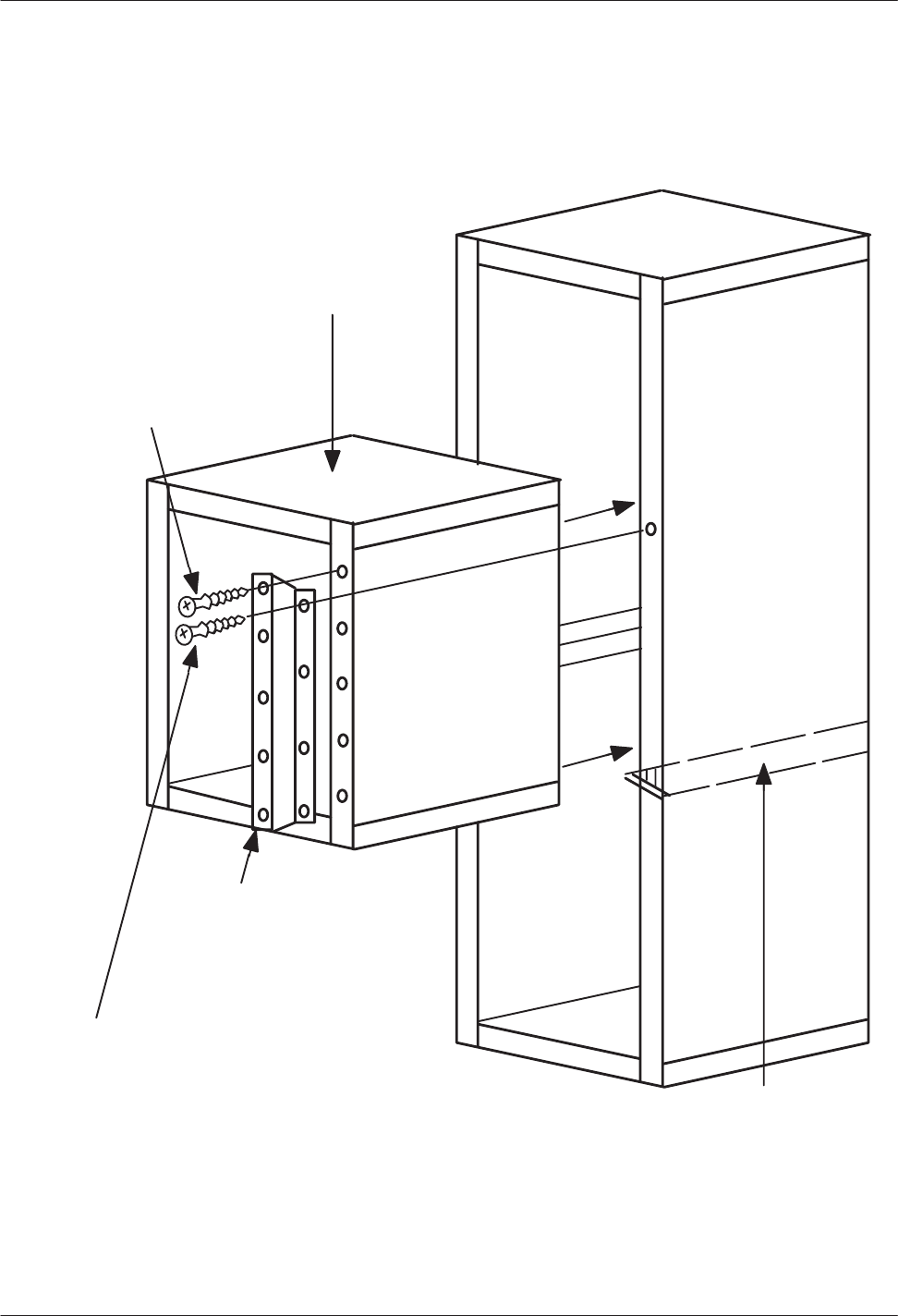
4-40
Installation and Maintenance
Volume
Octel Overture 200/300 Serenade 3.0
PB60014–01
4.8 RACK
MOUNT INST
ALLA
TION, OCTEL OVERTURE 300
The Octel Overture 300 can be installed in a 19-inch rack. Figure 4-9 illustrates a rack-mount installation.
Figure 4-9
Octel Overture 200/300 Cabinet Installed in 19-Inch Rack
10 mounting screws
(supplied in Overture
Rack Mount Kit)
8 mounting screws
(supplied by rack manufacturer)
2 rackĆmounting brackets,
one each side (supplied in
Overture Rack Mount Kit)
2 support rails
(supplied by rack manufacturer)

Installation
4-41
Octel Overture 200/300 Serenade 3.0
PB60014–01
Preinstallation
Determine
whether the rack to be used is of a suitable size and strength to hold the Octel Overture 300.
At maximum configuration, the server can weigh as much as 220 pounds and might be too heavy for
some racks. Make sure that the rack is structurally sound before and after the server is installed. Remove
any rack casters, as they make the rack less stable. T
o increase stability further, you might need to bolt
the rack to the floor or provide some other means of support.
Obtain support rails from the rack manufacturer
. Install the rails in the rack to support the weight of the
server
. Unless the rack has threaded holes in vertical mounting rails, the rack manufacturer must also
provide speed nuts and rack-mounting screws for securing the front of the server to the rack.
If the Octel Overture 300 is currently in service, make sure that all cables connected to the back of the
server are long enough to reach the server when it is mounted in the rack.
The front and back of the rack must remain open to ensure proper air flow through the server
. Mount the
server low enough in the rack so that any service person can easily service the server while standing on
the floor
.
The following equipment and tools are required:
Quantity Description
1
Octel Overture 300 message server
1
Rack mount kit, Part No.
740-6036-001, which
includes two mounting brackets and 10 mounting
screws
1
19-inch rack
2
Support rails, rated for at least 220 pounds
8
Rack-mounting screws
8
Speed nuts, if required
1
Phillips screwdriver
Installation
Use the following steps to install the Octel Overture 300 in a rack:
1.
Open and remove the front door of the server
.
2.
Put on an antistatic wrist strap. Connect it to an unpainted portion of the cabinet.
3.
Make sure that the power to the Octel Overture 300 is turned OFF
.
4.
Remove the power
-supply unit, fan tray
, and all disk drives to reduce the weight of the cabinet and to
protect the disk drives from damage. Refer to the Hardware Replacement chapter
, Hardware
Removal section, for instructions about removing assemblies. Make sure to note the slot position of
all disk drives, because they must be replaced in the same slots. Y
ou do not need to remove PCAs in
slots A1 through A14.

4-42
Installation and Maintenance
Volume
Octel Overture 200/300 Serenade 3.0
PB60014–01
5. If
the message server has been in service, disconnect all cables from the rear of the cabinet. Make
sure to note the cable positions, because they must be reconnected exactly as they were.
6.
Install the rack-mounting brackets to the front vertical flanges of the Octel Overture 300 cabinet with
the screws provided, using a Phillips screwdriver
. Refer to Figure 4-9.
7.
Determine the location of the Octel Overture 300 in the rack, and install the support rails from the
rack manufacturer appropriately
.
8.
Using a tape measure, determine where the speed nuts provided by the manufacturer should clip on
the rack vertical rails to line up with the holes in the Octel Overture 300 rack-mounting brackets.
The preceding step is not necessary if the rack has threaded holes in the vertical mounting
rails.
9. T
wo people are needed to insert the cabinet into the rack. Lift the partially empty cabinet onto the
support rails in the rack. You might need to remove the leveling feet on the bottom of the cabinet, so
that the cabinet can sit correctly on the support rails.
10.
Secure the cabinet to the rack using the mounting screws provided by the rack manufacturer
.
11.
Install all assemblies removed in step 4, and secure them to the cabinet. Refer to the Hardware
Replacement chapter for instructions about installing assemblies.
12.
If the message server has been in service, install all cables in the back of the cabinet as they were
before beginning this procedure. If not, follow the additional installation procedures in the
Connecting the Phone System to the Octel Overture 300 section of this chapter
.
13. T
urn on the power to the message server
, and test its operation. Refer to the Octel Overture 300
T
esting section in this chapter
.
14.
Replace and lock the front door of the cabinet.
Removal
T
o remove the Octel Overture 300 from a vertical rack, perform the following steps:
1.
Open and remove the front door of the cabinet.
2.
Put on an antistatic wrist strap. Connect it to an unpainted portion of the cabinet.
3.
Make sure that the Octel Overture 300 is turned OFF
.
4.
Remove the power
-supply unit, fan tray
, and all disk drives to reduce the weight of the cabinet and to
protect the disk drives from damage. Refer to the Hardware Replacement chapter for instructions
about removing assemblies. Make sure to note the slot position of all disk drives, because they must
be replaced in the same slots. Y
ou do not need to remove PCAs in slots A1 through A14.
5.
If the message server has been in service, disconnect all cables from the rear of the cabinet. Make
sure to note the cable positions, because they might need to be reconnected exactly as they were.
6. T
wo people are needed to remove the cabinet from the rack. Lift the partially empty cabinet out of
the rack, and place it on the floor
.
7.
Install all assemblies removed in step 4, and secure them to the cabinet. Refer to the Hardware
Replacement chapter for instructions about installing assemblies.
8.
Remove the rack-mount hardware.

Installation
4-43
Octel Overture 200/300 Serenade 3.0
PB60014–01
9. If
the Octel Overture 300 is to be shipped, refer to the Receiving the Equipment, Reshipping section,
in this chapter
.
10.
If the Octel Overture 300 is to be returned to service, install all cables at the back of the cabinet as
they were before beginning this procedure.
11. T
urn ON the power to the server and test the message server
’
s operation. Refer to the Octel Overture
300 T
esting section in this chapter
.
12.
Replace and lock the front door to the cabinet.

4-44
Installation and Maintenance
Volume
Octel Overture 200/300 Serenade 3.0
PB60014–01
4.9 SOFTWARE
INST
ALLATION
System
parameters and customer
-provided information are entered in the message-server memory
through a terminal and a two-part configuration program. Use the INST
ALL program to enter
information for new installations; use the UPDA
TE program for verification and to change the
configuration database. This section is an overview of the software installation. Detailed directions for all
steps are found in the
Configuration
volume
.
Using INSTALL — Entering the Configuration Database
After
the operating system has been loaded and the self-test completed, the Octel Overture 200/300 is
ready for you to enter the password. After a valid password is entered, begin the INST
ALL program. At
the @ prompt, type
INSTA
When prompted, enter data as described in the
Configuration
volume to define the database.
Answer
Y
when the Octel Overture 200/300 asks whether you want to save the configuration to diskette.
Follow the Octel Overture 200/300 directions to insert the configuration diskette in the floppy-disk drive.
Using
UPDA
TE
Use
the UPDA
TE program for verifying and modifying the configuration database, as described in the
following two sections.
Verifying the Configuration Database
After
you finish the message server configuration, the terminal again displays the
@
prompt. T
o get a
printout of the database, enter the UPDA
TE program. At the @ prompt, type
UP
The terminal displays the dot (.) prompt. At the dot, type
L ALL
Check
the printout with the configuration forms and verify that the data is correct. If correct, exit from
the program by typing
E
If any of the data is incorrect, follow the instructions in the
Configuration
volume when changing the
database. When any changes are made in the configuration database, always save the information on a
diskette when exiting the UPDA
TE program. Answer
Y
when the Octel Overture 200/300 asks whether
you want to save the configuration to diskette.
Modifying the Configuration Database
You
can modify
, add, or delete message-server configuration data. When the terminal or teleprinter
displays the @ prompt, type
UP
and press
to access the UPDA
TE program. At the dot (.) prompt,
you can enter an UPDA
TE command. Refer to the
Configuration
volume, UPDA
TE T
able chapter
,
Understanding Update section.
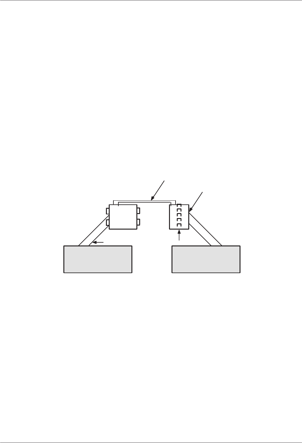
Installation
4-45
Octel Overture 200/300 Serenade 3.0
PB60014–01
4.10 CONNECTING
THE PHONE SYSTEM T
O THE OCTEL
OVERTURE 200/300
After
you have verified that both the message server and the PBX are configured correctly
, you must
connect the Octel Overture 200/300 to the PBX.
Connection
Overview
The
Octel Overture 200/300 installation involves connecting 25-pair cables from the rear of the Octel
Overture 200/300 to a 66M4-4W connector block, which is mounted on a backboard. Each 25-pair cable
supports one slot on the Octel Overture 200/300. The Octel Overture 200/300 is then connected with
jumper wire to the PBX.
It is recommended that the PBX extensions to be associated with the Octel Overture 200/300 be
terminated on a 66M connector block, or equivalent, for ease of installation and fault isolation, as shown
in Figure 4-10.
Figure 4-10 T
ypical Octel Overture 200/300 Connections
66M4-4W 66M
Cross-connect
wir
e
– – – – – –
– – – – – –
– – – – – –
– – – – – –
– – – – – – – – – –
– – – –
– – – –
– – – –
– – – –
Bridge clips
25-pair cable
PBX extensions
terminate her
e
Octel Overtur
e 200/300
Verifying the Equipment
The
following equipment is required for installation of the Octel Overture 200/300:
PBX extensions associated with the Octel Overture 200/300, to be terminated on a 66M connector
block, or equivalent
Octel Overture 200/300 installation kit
DAC installation kit, Part No. 740-6045-001, if installing DAC
Each kit installs four DAC slots. T
o determine the number of DAC installation kits to order, divide
the total number of DAC slots by four. The kit contains the following:
One DAC I/O Panel Assembly
, Part No. 740-6051-001
One d.c. Power Supply Assembly
, Part No. 740-6050-001

4-46
Installation and Maintenance
Volume
Octel Overture 200/300 Serenade 3.0
PB60014–01
The
short 50-pin cable is not included in the installation kit. Order the cable separately
, one cable
for each slot.
Each line card installation kit, Part No. 740-6034-001, installs four line-card slots. T
o determine the
number of line-card installation kits to order, divide the total number of line-card slots by four
. The kit
contains the following:
One 66M4-4W connector block, Part No. PJ86001-01
Four 10-foot cables with male-to-female 25-pair connectors, Part No. SA10079-02
T
wo self-tap 10 x 5/8 PH sheet-metal screws, Part No. HH53024-01
A line-card installation kit is required if you are installing an integration card for the Octel Overture
200/300.
For more information about the installation of an integration card, refer to the appropriate chapter
in the
Integration
volume. For information about installing the EntryW
orks ACP card, refer to the
W
orks for Serenade
documentation.
Connector
Blocks
Figure 4-1
1
shows the connector block that is to be used to add wiring for the Octel Overture 200/300.
The block is supplied in the installation kit. The connector block has 50 separate punchdown contacts in
each column, with each column wired to an amphenol connector at the side of the block. Column A is
wired to jack 1, column B to jack 2, etc.
Mount the block to the backboard in the location that you have specified. Mounting screws are provided
when the block is ordered. Mount the block with the word “T
OP” (embossed in the plastic, located at the
upper left side of the block) facing up (refer to Figure 4-1
1).
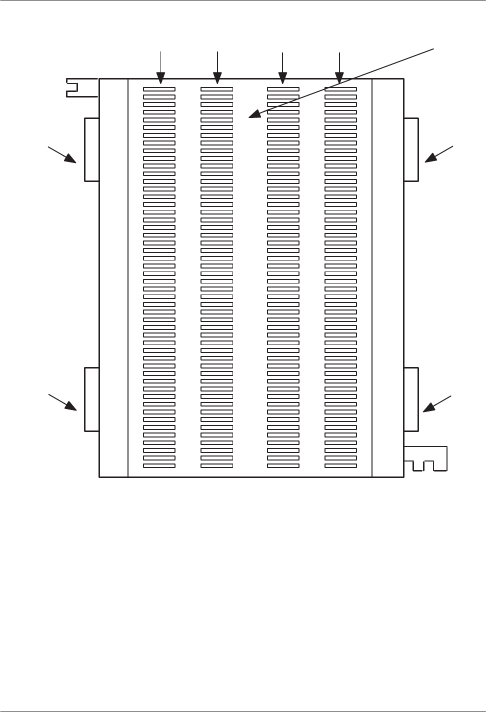
Installation
4-47
Octel Overture 200/300 Serenade 3.0
PB60014–01
Figure 4-11
Connector Block
A B C DColumn =
1
2
3
4
5
6
7
8
9
10
11
12
13
14
15
16
17
18
19
20
21
22
23
24
25
Pair
Number
Jack 3 (C)
to slot 3
Jack 4 (D)
to slot 4
Jack 1 (A)
Jack 2 (B)
to slot 2
To p
to slot 1
Wiring
In
most cases, the existing wiring is not consistent in its placement of the connections. To isolate faults
quickly
, it is recommended that the slots be connected in numerical order
, allowing for known or
anticipated expansion. At least, make sure that the slot and port numbers can be translated to extension
numbers that are meaningful to the servicing technician.
Figure 4-12 is an example of a 16-port message server that requires one connector block and four 25-pair
cables. From the rear of the cabinet, connect the first 25-pair cable from P1 to jack position 1 of the
66M4-4W connector block, or column A; connect the second 25-pair cable from P2 to jack position 2, or
column B; etc.
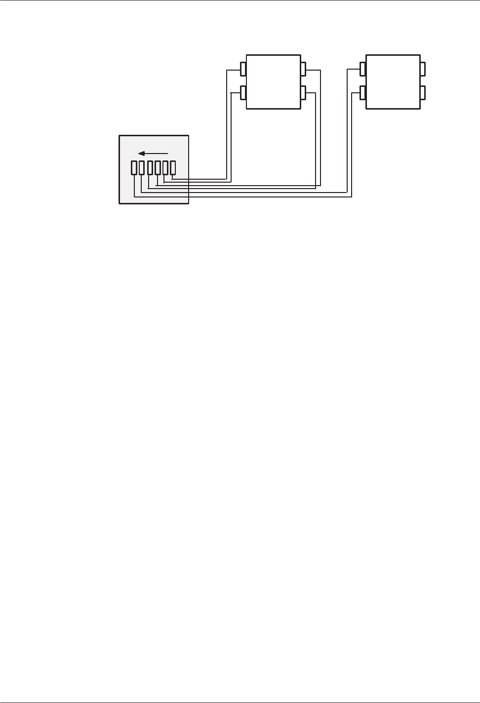
4-48
Installation and Maintenance
Volume
Octel Overture 200/300 Serenade 3.0
PB60014–01
Figure 4-12
Example of Server-to-Block Connections
Octel
Overture
200/300
66M4-4W 66M4-4W
P1P6
For maximum configuration, three connector blocks and twelve 25-pair cables are required.
The actual wiring (cross-connections from the 66M4-4W connector block to the 66M block, or
equivalent), can be made in any manner consistent with good telephony practices. Follow these two
guidelines when punching down wires to ensure correct installation:
Do not
touch the pins on the connector block with your fingers or with dirty tools. The pins could
oxidize and open after a few months.
T
ip is always above ring on the block when a pair is punched down. Refer T
able 4-7, M4-4W
Connector
-Block Designators.

Installation
4-49
Octel Overture 200/300 Serenade 3.0
PB60014–01
Table 4-7
66M4-4W Connector Block Designators
PR Cable Column
# Wire# Color A Slot Port B Slot Port C Slot Port D Slot Port
1
2
3
4
5
6
7
8
9
10
11
12
26
1
27
2
28
3
29
4
30
5
31
6
32
7
33
8
34
9
35
10
36
11
37
12
WHT-BLU
BLU-WHT
WHT-ORG
ORG-WHT
WHT-GRN
GRN-WHT
WHT-BRN
BRN-WHT
WHT-SLT
SLT-WHT
RED-BLU
BLU-RED
RED-ORG
ORG-RED
RED-GRN
GRN-RED
RED-BRN
BRN-RED
RED-SLT
SLT-RED
BLK-BLU
BLU-BLK
BLK-ORG
ORG-BLK
TA1
RA1
TA2
RA2
TA3
RA3
TA4
RA4
TA5
RA5
TA6
RA6
TA7
RA7
TA8
RA8
TA9
RA9
TA10
RA10
TA11
RA11
TA12
RA12
1
1
1
1
1
1
1
1
1
1
2
2
3
3
4
4
TB1
RB1
TB2
RB2
TB3
RB3
TB4
RB4
TB5
RB5
TB6
RB6
TB7
RB7
TB8
RB8
TB9
RB9
TB10
RB10
TB11
RB11
TB12
RB12
2
2
2
2
2
2
2
2
1
1
2
2
3
3
4
4
TC1
RC1
TC2
RC2
TC3
RC3
TC4
RC4
TC5
RC5
TC6
RC6
TC7
RC7
TC8
RC8
TC9
RC9
TC10
RC10
TC11
RC11
TC12
RC12
3
3
3
3
3
3
3
3
1
1
2
2
3
3
4
4
TD1
RD1
TD2
RD2
TD3
RD3
TD4
RD4
TD5
RD5
TD6
RD6
TD7
RD7
TD8
RD8
TD9
RD9
TD10
RD10
TD11
RD11
TD12
RD12
4
4
4
4
4
4
4
4
1
1
2
2
3
3
4
4
13
14
15
16
17
18
19
20
21
22
23
24
25
38
13
39
14
40
15
41
16
42
17
43
18
44
19
45
20
46
21
47
22
48
23
49
24
50
25
BLK-GRN
GRN-BLK
BLK-BRN
BRN-BLK
BLK-SLT
SLT-BLK
YEL-BLU
BLU-YEL
YEL-ORG
ORG-YEL
YEL-GRN
GRN-YEL
YEL-BRN
BRN-YEL
YEL-SLT
SLT-YEL
VIO-BLU
BLU-VIO
VIO-ORG
ORG-VIO
VIO-GRN
GRN-VIO
VIO-BRN
BRN-VIO
VIO-SLT
SLT-VIO
TA13
RA13
TA14
RA14
TA15
RA15
TA16
RA16
TA17
RA17
TA18
RA18
TA19
RA19
TA20
RA20
TA21
RA21
TA22
RA22
TA23
RA23
TA24
RA24
NOT
USED
1
1
1
1
1
1
1
1
5
5
6
6
7
7
8
8
TB13
RB13
TB14
RB14
TB15
RB15
TB16
RB16
TB17
RB17
TB18
RB18
TB19
RB19
TB20
RB20
TB21
RB21
TB22
RB22
TB23
RB23
TB24
RB24
2
2
2
2
2
2
2
2
5
5
6
6
7
7
8
8
TC13
RC13
TC14
RC14
TC15
RC15
TC16
RC16
TC17
RC17
TC18
RC18
TC19
RC19
TC20
RC20
TC21
RC21
TC22
RC22
TC23
RC23
TC24
RC24
3
3
3
3
3
3
3
3
5
5
6
6
7
7
8
8
TD13
RD13
TD14
RD14
TD15
RD15
TD16
RD16
TD17
RD17
TD18
RD18
TD19
RD19
TD20
RD20
TD21
RD21
TD22
RD22
TD23
RD23
TD24
RD24
4
4
4
4
4
4
4
4
5
5
6
6
7
7
8
8

4-50
Installation and Maintenance
Volume
Octel Overture 200/300 Serenade 3.0
PB60014–01
4.11 OCTEL
OVERTURE 200/300 TESTING
The
Octel Overture 200/300 should always be checked for proper operation after the configuration
database is installed or changes are made. In addition to the message-server test, other tests should be
made before the Octel Overture 200/300 is connected. These tests are described in this section. The tests
require the following equipment:
-
Three touchtone telephones; label the telephones as telephone A, telephone B, and telephone C
-
One terminal, directly connected to the Octel Overture 200/300, SP1 or J1, with an RS-232C cable
-
One hard copy of the configuration database
-T
wo extensions for testing, connected to RJ1
1 jacks (in addition to the extension associated with the
Octel Overture 200/300
-
One modular adapter
, Arminger 8-position modular adapter
, Part No. AA-2560A, or equivalent, is
recommended
.
These tests assume that no other calls are being made to the Octel Overture 200/300. If calls are
received, the port status could become confusing and might af
fect the test results.
Operational Test T
o V
erify Dial T
one on PBX Extensions
Verify
that dial tone is present on each
PBX
extension associated with the
Octel Overture 200/300, as
follows:
1.
Disconnect the 25-pair cables from the back of the Octel Overture 200/300.
2.
Connect the modular adapter to the 25-pair cable associated with slot one.
3.
Connect a touch-tone single-line telephone to the first jack position of the adapter
.
.
Only the first four jack positions of the modular adapter are used for each cable.
4.
Go of
f-hook. Is dial tone present?
YES '
Continue for all extensions and cables, for each slot configured in the message
server
. Proceed to the test in the next section.
NO '
Determine the cause and correct the problem before continuing.
Extension
Number Check
Verify
that the PBXextension numbers match the Octel Overture 200/300
SLOTS T
able, as follows:
1.
Refer to the configuration database listing, specifically to the SLOTS T
able.
2.
Connect the telephone labeled B to the modular
-adapter position associated with port 1.
3.
Connect the telephones labeled A and C to the two test telephone RJ1
1 jacks.
4.
From telephone A, enter the extension number associated with telephone B.
5.
Does telephone B ring?
YES '
Answer the call, verify the circuit quality
, and move telephone B to the next Octel
Overture 200/300 RJ1
1. Continue the procedure until all extensions are tested, then
proceed to the test in the next section.
NO '
Determine the cause and correct the problem before continuing.

Installation
4-51
Octel Overture 200/300 Serenade 3.0
PB60014–01
PBX Functional Test
Verify
that each Octel Overture 200/300
port extension can initiate a transfer by doing a hookswitch flash
and a transfer code or just a hookswitch flash, before entering an extension number
. Also, verify that you
can reconnect to the caller when the extension called is not answered or busy
. Perform the following steps:
1.
Connect telephone B to the modular
-adapter position associated with port 1 of the Octel Overture
200/300.
2.
From telephone A, call the extension number associated with telephone B.
3.
Answer telephone B, and perform a hookswitch flash.
4.
Does the PBX provide a stutter or solid dial tone after the hookswitch flash?
YES
If either tone is present, continue to step 5
NO
Stop and correct the problem before continuing.
5.
Enter the transfer initiate code, if any
, then enter the extension number associated with telephone C.
6.
After several ringbacks, perform a hookswitch flash and reconnect code, if required, to reconnect to
telephone A.
7.
Did telephone C stop ringing? Were you get reconnected to telephone A, which was on hold?
YES
Connect telephone B to the next Octel Overture 200/300 port extension and
continue until the extensions for each port are tested.
NO
Determine the cause and correct the problem before continuing.
8.
Make telephone C busy by taking it of
f-hook. Then repeat the test, starting with step 1 and calling a
busy extension instead of the ring-no-answer extension.
The extension number connected to telephone C should start with the same first digit as those
configured in the USER T
able.
Test for Calls to the Intercept Extension (Attendant)
Verify
that each extension can transfer a call to the intercept extension (attendant), as follows:
1.
Connect telephone B to the modular
-adapter position associated with port 1 of the Octel Overture
200/300.
2.
From telephone A, call the extension number associated with telephone B.
3.
Answer telephone B, and perform a hookswitch flash and enter the transfer code, if required. Press
(or the attendant’
s extension number), then hang up telephone B.
4.
Did telephone A connect with the operator?
YES
Continue test for all extensions, then proceed to the test in the next section.
NO
Determine the cause and correct the problem before continuing.
Some PBXs do not allow a blind (unscreened) transfer to an attendant. If this is the case, do
not assign Attribute 15 — TRANSFER T
O A RINGING EXTENSION, to the COS for this
mailbox.

4-52
Installation and Maintenance
Volume
Octel Overture 200/300 Serenade 3.0
PB60014–01
When
all Octel Overture 200/300 port extensions pass these tests, proceed by connecting the 25-pair
cables to the Octel Overture 200/300 and test the message server for standard operation. The Octel
Overtur
e 200/300
must initialize each of the PBX ports.
T
o verify that all the ports ar
e
initialized, at the
@
pr
ompt, type
PS.
All ports should return
IDL.
Test
for Call to a Ring-No-Answer Extension
The
extension to be called must have a valid first digit (a mailbox with this first digit must already
exist in the USER T
able) or be entered in the USER T
able as a mailbox (mailbox number same as
the extension number and a COS).
V
erify that the Octel Overture 200/300
correctly handles a ring-no-answer (RNA) call.
1.
From telephone A, call the extension associated with port 1.
2.
Did the Octel Overture 200/300 answer with the correct company greeting (a custom greeting or the
generic greeting)?
YES Continue.
NO
Determine the cause and correct the problem before continuing.
3.
Enter the extension number for telephone C.
4.
Did the Octel Overture 200/300 respond with the prompt:
“Thank you, just a
moment .
. .” (Primary
Answer Mode example)?
YES Continue.
NO
Determine the cause and correct the problem before continuing.
5.
After a predetermined interval (defined by the entry in the INFORMA
TION T
able for ringbacks
before no answer), does the message server reconnect and speak the prompt
“Extension XXX doesn’
t
answer
. Please leave a message at the tone, or enter another extension number
, or pr
ess zer
o for
assistance”?
If the mailbox has not been entered in the USER T
able, the Octel Overture 200/300 does not
of
fer to take a message.
YES
Press
, then hang up.
NO
Determine the cause and correct the problem before continuing.
6.
Repeat the test for each Octel Overture 200/300 port.
Test
for Calls to a Busy Extension
Verify
that the Octel Overture 200/300
properly handles a call directed to a busy extension.
1.
From telephone A, call the extension associated with port 1.
2.
Did the Octel Overture 200/300 answer with the correct company greeting?
YES Continue.
NO
Determine the cause and correct the problem before continuing.

Installation
4-53
Octel Overture 200/300 Serenade 3.0
PB60014–01
3. Make
sure that telephone C is busy by taking it of
f-hook. Enter the extension number for telephone C.
4.
Did the Octel Overture 200/300 respond with the prompt
“Thank you, just a
moment . . .”
(primary
answer mode example)?
YES Continue.
NO
Determine the cause and correct the problem before continuing.
5.
After a short interval, does the message server reconnect and speak the prompt
“Extension XXX is
busy
. Please leave a message at the tone, or enter another extension number
, or pr
ess zer
o for
assistance”?
YES
Press
, then hang up.
NO
Determine the cause and correct the problem before continuing.
6.
Repeat the test for each Octel Overture 200/300 port.
Hunt Group Operation Test
Verify
the hunting sequence, as follows:
The terminal command
PS
displays the current status of each Octel Overture 200/300 port. A
three-character abbreviation denotes the state of each port. Refer to the Maintenance Commands
chapter for more information about using the PS command and the meaning of the states.
1.
From the system level
@
prompt, enter
PS.
2. Does
the port status show the
IDL
state for all positions? If not, determine the cause and correct the
problem before continuing.
a.
Some ports may be in the
TST
(test) state momentarily
, because of online diagnostics. If a port
is in the
TST state,
enter
PS
several times, before deciding whether the port is in trouble or
self-test is running. Self-test runs every 5 minutes; if a problem is encountered, it is entered in
the Hardware Error T
able.
b.
If other calls are being made into the Octel Overture 200/300, all ports might not be idle. If they
are not all idle, check to see whether anyone else is calling.
If the terminal is connected remotely
, one of the ports shows the modem as
MOD.
3.
From telephone A, enter the extension number or access code associated with the Octel Overture
200/300 hunt group.
4.
Does the Octel Overture 200/300 answer correctly? If not, determine the cause and correct the
problem before continuing.
5.
From the terminal, enter
PS.
The port status should show the port in
WFD
(wait for digits) state when an incoming call is
answered.
6.
Did the correct port answer
, based upon how the PBX is programmed for hunting groups?
YES Continue.
NO
Determine the cause and correct the problem before continuing.
7.
From telephone A, press
and hang up after the message server says
“good-bye.”

4-54
Installation and Maintenance
Volume
Octel Overture 200/300 Serenade 3.0
PB60014–01
8. Busy
out the PBX extension identified in step 6 above.
9.
Continue the process from step 3 until all ports have been busied out.
Testing
Fail-Safe Operation
The
fail-safe port operation test comprises the all-ports-busy condition and the ring-no-answer condition.
All
Ports Busy
Perform
the following steps for the all-ports-busy test:
1.
While all ports are busied out, use telephone A to enter the extension number or access code of the
hunt group.
2.
Does the call overflow to the correct answering extension as determined for fail-safe operation?
YES Continue.
NO
Determine the cause and correct the problem before continuing.
Some PBXs might not support hunt-group overflow; in which case, the caller could
experience a ring no-answer condition until a port is available to accept the call.
3.
Remove the busy condition from all Octel Overture 200/300 port PBX extensions.
Port
Ring-No-Answer
Perform
the following steps for the port ring-no-answer test:
1.
Disconnect the 25-pair cables associated with the Octel Overture 200/300.
2.
From telephone A, enter the hunt-group extension number or access code associated with the
extensions connected to the Octel Overture 200/300.
3.
Is the call diverted to the correct alternate answer point when the Octel Overture 200/300 does not
answer?
YES Continue.
NO
Determine the cause and correct the problem before continuing.
4.
Reconnect the modular line cords.
5.
From the terminal, enter
TE C 1.
The Octel Overture 200/300 should respond, showing that each
port is forwarded until all ports have been forwarded.
6.
Enter
PS
to verify that all ports are in the
FWD
(forwarded) state.
7.
From telephone A, enter the hunt-group extension number or access code.
8.
Is the call forwarded to the correct position as specified in the call forwarding string (System
Parameter 45 — SYSTEM RELOAD FOR
W
ARD STRING)?
YES Continue.
NO
Determine the cause and correct before continuing.
9.
From the terminal, enter
TE C 2
to cancel call forwarding. The Octel Overture 200/300 should
respond with
ALL PORTS INITIALIZED.

Installation
4-55
Octel Overture 200/300 Serenade 3.0
PB60014–01
10. From
telephone A, enter the hunt-group extension number or access code.
11.
Does the Octel Overture 200/300 answer correctly?
YES Continue.
NO
Determine the cause and correct before continuing.
12.
Enter
PS
at the terminal.
13. V
erify that all ports are in the
IDL
state and that the cancel forwarding string (System Parameter 46
— SYSTEM RELOAD CANCEL FOR
W
ARD STRING) is correct. If any ports still show
FWD
, use
TE C 2 x,
where x is the port number
, to cancel forwarding. If cancel forwarding does not work,
determine the cause and correct it before continuing.
Test
to Verify T
runk T
o Octel Overture 200/300 Operation
1.
From the terminal, enter the
PS
command.
2.
Does the port status show all ports in the IDL state?
YES Continue.
NO
Determine the cause and correct the problem before continuing.
3.
From telephone A, call outside the PBX and back in on trunks dedicated to the hunt group.
4.
Does the Octel Overture 200/300 answer correctly?
YES Continue.
NO
Determine the cause and correct the problem before continuing.
5.
From the terminal, enter the
PS
command.
6.
Does the port that answered show
WFD
state?
YES Continue.
NO
Determine the cause and correct the problem before continuing.
7.
From telephone A, enter the extension number associated with telephone C. The Octel Overture
200/300 responds with
“Thank you, just a moment.”
8.
Does telephone C ring?
YES Continue.
NO
Determine the cause and correct the problem before continuing.
9.
Enter the
PS
command. Port status should show port 1 in the AIC (assisted incoming call/automated
attendant) state.
10.
Answer telephone C. Does the Octel Overture 200/300 say
“Beep, beep, beep....Connecting”
and
transfer the incoming trunk to telephone C?
YES Continue.
NO
Determine the cause and correct the problem before continuing.
11.
From the terminal, enter the
PS
command, and verify that the port state is
IDL.
12.
Busy-out the port that answered.

4-56
Installation and Maintenance
Volume
Octel Overture 200/300 Serenade 3.0
PB60014–01
13. Repeat
the procedure from step 3 for all ports, until all ports are busied out. V
erify that calls can be
placed through the Octel Overture 200/300 from each port.
14.
From telephone A, call out and back in on a trunk dedicated to the hunt group.
15.
Does the call overflow to the correct destination?
YES Continue.
NO
Determine the cause and correct the problem before continuing.
Some PBXs might not support overflow
, in which case a ring-no-answer condition could be
encountered.
16.
Remove the busy condition from all Octel Overture 200/300 port extensions.
17.
Repeat steps 3 through 13 except call an extension that does not answer
, and then repeat it by calling
a busy extension.
Test
to Verify T
runks
1. From
telephone A, call outside the PBX and back in on the first trunk dedicated to the Octel
Overture 200/300.
2.
Does the Octel Overture 200/300 answer correctly?
YES Continue.
NO
Determine the cause and correct the problem before continuing.
3.
Repeat the procedure from step 1 for each trunk, until all hunts have been tested. V
erify that each
trunk is answered by the Octel Overture 200/300 with the correct greeting.
T
oll-free service lines can be tested individually
, even if they are bands from other areas, by
using the “plant test” number
. Get these from the PE (Public Exchange) if you do not know
them.
Test for Calls to the Intercept Extension
Verify
that the Octel Overture 200/300 can transfer a call to the intercept position (attendant) when the
caller does nothing or presses
, as follows:
1.
From telephone A, call the extension associated with port 1.
2.
Does the Octel Overture 200/300 answer correctly?
YES Continue.
NO
Determine the cause and correct the problem before continuing.
3.
Listen to the complete company greeting. Do nothing, let the Octel Overture 200/300 time out, and
transfer the call to the attendant (do not enter any digits).
4.
Did you reach the attendant?
YES
Continue for all ports.
NO
Determine the cause and correct the problem before continuing.
5.
Repeat the procedure except press
instead of waiting for a timeout.

Installation
4-57
Octel Overture 200/300 Serenade 3.0
PB60014–01
6. From
telephone A, call out and back in on a trunk dedicated to the hunt group. When the Octel
Overture 200/300 answers, let the message server time out.
7.
Does the Octel Overture 200/300 transfer the call to the intercept position?
YES Continue.
NO
Determine the cause and correct the problem before continuing.
Message
W
aiting Test
1. From
telephone A, call out and back in on a trunk dedicated to a Octel Overture 200/300 port.
2.
Does the Octel Overture 200/300 answer correctly?
YES Continue.
NO
Determine the cause and correct the problem before continuing.
3.
Make sure that telephone C is busy
, by taking it of
f-hook. Enter the extension number associated
with telephone C.
4.
After a predetermined interval, the Octel Overture 200/300 should reconnect, and at telephone A you
should hear
,
“Extension XXX is busy
. Please leave a message at the tone, or enter another extension
number
, or pr
ess zer
o for assistance.”
5.
Leave a test message for telephone C.
A message is not delivered to a mailbox unless it is at least 4.5 seconds long. The mailbox
must be entered in the USER T
able for the Octel Overture 200/300 to of
fer to take a message.
6.
The Octel Overture 200/300 should now initiate a message-waiting-notification call (ASAP message
waiting) to the extension associated with telephone C.
If all ports are allowed to make outcalls, the call is not attempted when three-fourths or more
of the ports are being used. Also, for message waiting, INFORMA
TION T
able Index 12 —
MESSAGE W
AITING NOTIFICA
TION, must be set to Y
.
7.
Does the Octel Overture 200/300 call the extension associated with telephone C?
YES Continue.
NO
Determine the cause and correct the problem before continuing.
8.
Answer telephone C. The Octel Overture 200/300 should respond with
“Extension XXX has X
messages. Ready
,”
or
“Extension XXX has X messages. Please enter your
security code.”
9.
Enter the security code, if asked, and press
to Listen to the test message.
10.
Does the message sound clear?
YES Continue.
NO
Determine the cause and correct the problem before continuing.
11.
Press
to Erase the message, then press
to exit the mailbox. Does the Octel Overture 200/300
respond with
“X messages will be erased”
?
YES
Press
to exit the message server
. The Octel Overture 200/300 should respond with
“good-bye.”
NO
Determine the cause and correct the problem.

4-58
Installation and Maintenance
Volume
Octel Overture 200/300 Serenade 3.0
PB60014–01
4.12 TESTING
THE INST
ALLA
TION AND TELEPHONE CHANGES
Use
the following checklist to help track any installation and telephone changes, as follows:
Use the “See Chapter” column for reference to the appropriate chapter in the
Installation and
Maintenance
volume for further information.
Enter the name of the person who is responsible for tracking an installation task in the “Person
Responsible” column.
Enter the date the installation task is to be completed in the “Scheduled” column.
Enter the final completion date in the “Completed” column.
Installation Task See
Chapter Person
Responsible Scheduled Completed
Receiving
the Equipment
Inspect for damage
Installation
Carton
Server
ac/dc cables secure
Printed circuit cards
Reshipping procedures
Preinstallation
Environment
Installation
Dust free (Y/N)
A
way from lar
ge motors (Y/N)
Server accessible (Y/N)
Power
Dedicated fuse or breaker
Dedicated 1
15-V
ac 60-Hz
receptacle
Other required equipment available
Modular line cord
RJ1
1 jacks or equivalent
CA
T or other ASCII terminal
Phillips screwdriver
RS-232C interface cable

Installation
4-59
Octel Overture 200/300 Serenade 3.0
PB60014–01
Installation Task CompletedScheduled
Person
Responsible
See
Chapter
PBX
Pr
eparation
Survey telephone system (Y/N)
Preparing the
Phone System
Additional touch-tone extensions (as
required)
Install and label the Octel Overture
200/300 ports
PBX COS changes for the
Octel Overture 200/300 port extensions
Forwarding
Of
f-site calls, no call restriction
Remove call waiting features
Permitted to transfer
, hold,
reconnect
Overflow for RNA/busy
Hunt Group 1
Hunt Group 2
Hunt Group 3
Hardwar
e Installation
Communicating with the message server
Octel Overture 200/300 installation
Configuration installation
Connecting the PBX to the
Octel Overture 200/300
Installation
Testing Installation
T
ools and equipment
Three touch-tone single line
telephones
CA
T or other ASCII terminal and
teleprinter
Database hardcopy
T
wo test extensions

4-60
Installation and Maintenance
Volume
Octel Overture 200/300 Serenade 3.0
PB60014–01
Installation Task CompletedScheduled
Person
Responsible
See
Chapter
Pass/Fail
T
ests
Step Description
Installation
1.
Pre-operation test of message
server
2.
Extension number check
3.
PBX function
4.
Call to intercept/attendant PBX
5.
Ring-no-answer extension
6.
Busy extension
7.
Hunt Group operation
8.
Fail-safe operation
9. T
runk to the Octel Overture
200/300 operation
10. V
erifying trunks
11.
Intercept extension
(the Octel Overture 200/300)
12.
Message waiting
Trunks
Quantity to the Octel Overture 200/300
Dedicate to hunt group(s)
Preparing The
Phone System
Group 1
Group 2
Group 3
No extension restriction, if applicable
T
runk-to-trunk capability (Y/N)
T
runk queuing (Y/N)
incoming only
two-way
Central Of
fice changes
Hunt Group
contains the Octel Overture
200/300 extension
circular hunting
overflow (Y/N)
trunks dedicated (circle one)
DDC, UCD, DIL, Dedicated

Octel
Overture 200/300 Serenade 3.0
PB60014–01
5
REPORTS
Chapter
Contents
5.1 Overview 5-1.
. . . . . . . . . . . . . . . . . . . . . . . . . . . . . . . . . . . . . . . . . . . . . . . . . . . . . . . . . . . . . . . . . . . . . . . . . . . . . . . . . .
5.2 Listing
and Clearing Reports
5-2.
. . . . . . . . . . . . . . . . . . . . . . . . . . . . . . . . . . . . . . . . . . . . . . . . . . . . . . . . . . . . . . . . .
Listing
a Report
5-2.
. . . . . . . . . . . . . . . . . . . . . . . . . . . . . . . . . . . . . . . . . . . . . . . . . . . . . . . . . . . . . . . . . . . . . . . .
Listing User Statistics (Selections 3 or 4) 5-3.
. . . . . . . . . . . . . . . . . . . . . . . . . . . . . . . . . . . . . . . . . . . . . . . . . .
Clearing
a Report
5-4.
. . . . . . . . . . . . . . . . . . . . . . . . . . . . . . . . . . . . . . . . . . . . . . . . . . . . . . . . . . . . . . . . . . . . . . .
5.3 System
Performance Report
5-5.
. . . . . . . . . . . . . . . . . . . . . . . . . . . . . . . . . . . . . . . . . . . . . . . . . . . . . . . . . . . . . . . . .
Call
Summary
5-7.
. . . . . . . . . . . . . . . . . . . . . . . . . . . . . . . . . . . . . . . . . . . . . . . . . . . . . . . . . . . . . . . . . . . . . . . . . .
Message
Summary
5-11.
. . . . . . . . . . . . . . . . . . . . . . . . . . . . . . . . . . . . . . . . . . . . . . . . . . . . . . . . . . . . . . . . . . . .
Digital
Network Performance Report
5-13.
. . . . . . . . . . . . . . . . . . . . . . . . . . . . . . . . . . . . . . . . . . . . . . . . . . . . .
5.4 Network
T
raf
fic Report
5-16.
. . . . . . . . . . . . . . . . . . . . . . . . . . . . . . . . . . . . . . . . . . . . . . . . . . . . . . . . . . . . . . . . . . . . .
To
Location
5-17.
. . . . . . . . . . . . . . . . . . . . . . . . . . . . . . . . . . . . . . . . . . . . . . . . . . . . . . . . . . . . . . . . . . . . . . . . . . .
Message Delivery 5-17.
. . . . . . . . . . . . . . . . . . . . . . . . . . . . . . . . . . . . . . . . . . . . . . . . . . . . . . . . . . . . . . . . . . . . .
Names Directory 5-18.
. . . . . . . . . . . . . . . . . . . . . . . . . . . . . . . . . . . . . . . . . . . . . . . . . . . . . . . . . . . . . . . . . . . . . .
Network Access Totals 5-18.
. . . . . . . . . . . . . . . . . . . . . . . . . . . . . . . . . . . . . . . . . . . . . . . . . . . . . . . . . . . . . . . . .
Feature Use Totals 5-18.
. . . . . . . . . . . . . . . . . . . . . . . . . . . . . . . . . . . . . . . . . . . . . . . . . . . . . . . . . . . . . . . . . . . . .
Digital Network Traf
fic Report
5-19.
. . . . . . . . . . . . . . . . . . . . . . . . . . . . . . . . . . . . . . . . . . . . . . . . . . . . . . . . . . .
5.5 User Message Statistics 5-21.
. . . . . . . . . . . . . . . . . . . . . . . . . . . . . . . . . . . . . . . . . . . . . . . . . . . . . . . . . . . . . . . . . . . .
Messaging Statistics 5-21.
. . . . . . . . . . . . . . . . . . . . . . . . . . . . . . . . . . . . . . . . . . . . . . . . . . . . . . . . . . . . . . . . . . .
5.6 User
Calling Statistics
5-23.
. . . . . . . . . . . . . . . . . . . . . . . . . . . . . . . . . . . . . . . . . . . . . . . . . . . . . . . . . . . . . . . . . . . . .
Call Processing Statistics 5-23.
. . . . . . . . . . . . . . . . . . . . . . . . . . . . . . . . . . . . . . . . . . . . . . . . . . . . . . . . . . . . . .
5.7 Disk
Usage Report
5-25.
. . . . . . . . . . . . . . . . . . . . . . . . . . . . . . . . . . . . . . . . . . . . . . . . . . . . . . . . . . . . . . . . . . . . . . . .
Total
System Message Storage
5-25.
. . . . . . . . . . . . . . . . . . . . . . . . . . . . . . . . . . . . . . . . . . . . . . . . . . . . . . . . .
Total
of Minutes
5-26.
. . . . . . . . . . . . . . . . . . . . . . . . . . . . . . . . . . . . . . . . . . . . . . . . . . . . . . . . . . . . . . . . . . . . . . .
Storage
Capacity Based on Message T
ype 5-26.
. . . . . . . . . . . . . . . . . . . . . . . . . . . . . . . . . . . . . . . . . . . . . . . .
5.8 Port Statistics 5-27.
. . . . . . . . . . . . . . . . . . . . . . . . . . . . . . . . . . . . . . . . . . . . . . . . . . . . . . . . . . . . . . . . . . . . . . . . . . . .
Individual Port Statistics 5-29.
. . . . . . . . . . . . . . . . . . . . . . . . . . . . . . . . . . . . . . . . . . . . . . . . . . . . . . . . . . . . . . . .
Port Group Statistics 5-29.
. . . . . . . . . . . . . . . . . . . . . . . . . . . . . . . . . . . . . . . . . . . . . . . . . . . . . . . . . . . . . . . . . . .
All Port Statistics 5-30.
. . . . . . . . . . . . . . . . . . . . . . . . . . . . . . . . . . . . . . . . . . . . . . . . . . . . . . . . . . . . . . . . . . . . . .
5.9 Mailbox Usage 5-31.
. . . . . . . . . . . . . . . . . . . . . . . . . . . . . . . . . . . . . . . . . . . . . . . . . . . . . . . . . . . . . . . . . . . . . . . . . . .
5.10 User
Status Detail
5-32.
. . . . . . . . . . . . . . . . . . . . . . . . . . . . . . . . . . . . . . . . . . . . . . . . . . . . . . . . . . . . . . . . . . . . . . . .
5.11 Integration
Calling Statistics
5-33.
. . . . . . . . . . . . . . . . . . . . . . . . . . . . . . . . . . . . . . . . . . . . . . . . . . . . . . . . . . . . . . . .
5.12 System Performance by COS 5-35.
. . . . . . . . . . . . . . . . . . . . . . . . . . . . . . . . . . . . . . . . . . . . . . . . . . . . . . . . . . . . . . .
Caller’s
Initial Action
5-35.
. . . . . . . . . . . . . . . . . . . . . . . . . . . . . . . . . . . . . . . . . . . . . . . . . . . . . . . . . . . . . . . . . . .
Subsequent Actions 5-37.
. . . . . . . . . . . . . . . . . . . . . . . . . . . . . . . . . . . . . . . . . . . . . . . . . . . . . . . . . . . . . . . . . . . .

Quick Reference Guide
Octel
Overture 200/300
Reports
Octel
Overture 200/300 Serenade 3.0
PB60014–01
Command Additional
Information
List Report @L R Shows
reports that can be listed. Individual reports are shown
below
. System Parameter 72 determines maximum lines per page
for reports.
Clear
Report
@C R Produces
a listing of reports that can be cleared. Options are:
1=System Performance and Port Statistic
2=Network T
raffic
3=User Call and Message Statistics.
The following reports are cleared:
User Message, User Calling and Mailbox Usage, User Status
Detail, and Integration Calling Statistics
INDIVIDUAL
REPORTS
System Performance
1When
clearing this report, the T
raf
fic Peg Count
T
able is set to
zero. The Port Statistics are cleared as well. Information pertains
to incoming calls, subsequent actions, progress of calls, and
mailbox information.
1 D Lists
the Digital Network Performance Report.
Network Traffic 2For
collocated and networked message servers. Information
pertains to route statistics, message delivery
, network access
totals, and feature use.
2 D Lists
the Network T
raf
fic Report for digital information only
.
User
Message Statistics
3Includes
current messages, messages left after various conditions,
logon, and date cleared.
User
Calling Statistics
4Includes
incoming calls, subsequent calls, calls abandoned, and
date cleared.
Disk
Usage
5Provides
statistics about the amount of voice and fax message
storage currently used on the message server
.
Port
Statistics
6Information
pertains to individual, group, fax channel information,
and all port statistics. This report is cleared when the System
Performance report is cleared.

Quick Reference Guide
Octel
Overture 200/300
Reports
Octel
Overture 200/300 Serenade 3.0
PB60014–01
Additional
Information
Command
Mailbox Usage 7Shows
mailbox usage time. Usage includes logon time and access
time.
User
Status Detail
8Shows
status information on mailbox access and time durations
associated with individual mailbox usage.
Integration
Calling
Statistics 9Shows
information about the type of non-integrated or integrated
calls a mailbox receives.
System
Performance by
COS 10 Provides
call and message statistics for ports/trunks by COS.

Reports
5-1
Octel Overture 200/300 Serenade 3.0
PB60014–01
5.1 OVERVIEW
Reports
provide statistics on the operation and usage of the Octel Overture
200/300 message server and
give owners the ability to monitor various operational aspects of the Octel Overture 200/300. Reports
may be accessed at any time through the system’
s administration terminal.
The Octel Overture 200/300 of
fers reports that provide both system-wide and mailbox statistics.
Information is collected and stored for ten reports.
1.
System Performance
2.
Network T
raffic
3.
User Message Statistics
4.
User Calling Statistics
5.
Disk Usage
6.
Port Statistics
7.
Mailbox Usage
8.
User Status Detail
9.
Integration Calling Statistics
10.
System Performance by COS

5-2
Installation and Maintenance
Volume
Octel Overture 200/300 Serenade 3.0
PB60014–01
5.2 LISTING
AND CLEARING REPORTS
Information
is collected and stored in various internal tables. The information accumulates until the
report is cleared. Reports can be listed without af
fecting the accumulated data. Once the command to
clear a report is entered, the values are reset to zero and resume accumulating.
Most reports show only the date they are run. At the top of reports 1, 2, 6 and 10 are two dates. The
“from” date and time indicate when the table was last cleared. The “to” date and time indicate when the
report was last printed. It is recommended that reports be listed and cleared on a regular basis. The
reports can display individual values up to 65535.
Beginning with Serenade Release 3.0, the following reports can display individual values up to
999,999.
System Performance
Digital Network Performance
Network T
raffic
Digital Network Activity
Disk Usage
Port Statistics
Integration Calling Statistics
System Performance by COS
For a report showing the attributes associated with the COS T
able, SCHEDULE T
able, and all
INFORMATION T
ables defined in the SCHEDULE T
able, refer to the
Configuration
volume, COS
chapter
, Using UPDA
TE chapter, for the
LIST
PROFILE
command.
This chapter describes all reports except the DID/E&M T
runk Interface report, which is detailed in
DID/E&M T
runk Interface Installation and Maintenance Manual
. For information about Direct
Access Cards, refer to the
Dir
ect Access Car
d (DAC) Installation and Maintenance Manual.
Listing a Report
Reports
are printed by selecting from the
LIST REPORT
menu. At the prompt @ enter
LIST REPORT,
or
L R
@
1. SYSTEM PERFORMANCE.
2. NETWORK TRAFFIC.
3. USER MESSAGE STATISTICS.
4. USER CALLING STATISTICS.
5. DISK USAGE.
6. PORT STATISTICS.
7. MAILBOX USAGE.
8. USER STATUS DETAIL.
9. INTEGRATION CALLING STATISTICS.
10. SYSTEM PERFORMANCE BY COS.
SELECT REPORT TO BE LISTED. (1 – 10, EMPTY LINE = EXIT)
:

Reports
5-3
Octel Overture 200/300 Serenade 3.0
PB60014–01
Select
the number of the report you wish to list.
Enter
L R #
(report number), to designate a specific report before the menu is displayed.
The prompts displayed after selecting a specific report (i.e., 1–0) vary slightly as shown in the following
sections. These
reports can be printed. Before each reported is displayed, the message server prompts
“READY PRINTER, THEN PRESS RETURN.”
Digital
Network Reports
The
System Performance report, 1, and the Network T
raf
fic report, 2, also print information about digital
networking. T
o print digital information for either report, after entering the report number
, enter
D
. For
example, to list digital network information for the System Performance report, at the : prompt, enter
:1 D
If
only 1 is entered for the System Performance report, the report does not include any digital networking
information. The digital networking System Performance report is printed
only
when
1 D
is entered. If
only 2 is entered for the Network T
raf
fic report, the report includes all networking information. Enter
2
D
to get information only about digital networking.
Listing
User Statistics (Selections 3 or 4)
Once
a User Statistics, Mailbox Usage, or User Status Detail report has been selected, the following
prompt displays:
ENTER DIGIT PATTERN (”?” FOR HELP):
CHECKING USER MAILBOXES...DONE.
READY PRINTER, THEN PRESS RETURN...
If
?
is entered for help, the following prompt displays:
Enter one of the following to select one or more mailboxes:
”ALL” – ALL MAILBOXES.
1–8 DIGITS – ONLY MAILBOXES BEGINNING WITH THIS DIGIT PATTERN.
EMPTY LINE – ABORT WITHOUT ACTION.
If
1–8 digits are entered, the list displays the mailboxes beginning with the digit(s) entered. In this
example the first digit is 5 and mailboxes are three digits long:
Entered Digits Mailboxes Displayed
5 All
mailboxes beginning with 5
56
All mailboxes beginning with 56
567
Only mailbox 567

5-4
Installation and Maintenance
Volume
Octel Overture 200/300 Serenade 3.0
PB60014–01
User
Statistics, Mailbox Usage, and User Status Detail reports are sorted by first digit. For example, if
mailboxes in the 2000 and 300 series are used, 2000 lists first.
If an invalid number is entered, the program displays the prompt:
“NO MATCH ON DIGIT PATTERN.”
Clearing a Report
To
clear reports, at the @ prompt type
CLEAR REPORT,
or
C R
@C R
After
this command is entered, following prompt displays:
1. SYSTEM PERFORMANCE (IN TRAFFIC PEGS) AND PORT STATISTICS.
2. NETWORK TRAFFIC.
3. USER MESSAGE, USER CALLING AND MAILBOX USAGE.
SELECT REPORT TO BE CLEARED.(1 – 3, EMPTY LINE = EXIT)
:
Select
the number of the report type you wish to clear
. The prompts displayed after selecting a report type
are specific to that report type.
When option 1 — System Performance and Port Statistics, is chosen, the following reports are cleared:
System Performance
System Performance by COS report
Digital Network Performance Report
Port Statistics
When option 3 — User Call and Message Statistics, is chosen, the following reports are cleared:
User Message Statistics
User Calling Statistics
Mailbox Usage
User Status Detail
Integration Calling Statistics
The Disk Usage report cannot be cleared. It always reflects current information.

Reports
5-5
Octel Overture 200/300 Serenade 3.0
PB60014–01
5.3 SYSTEM
PERFORMANCE REPORT
1. SYSTEM
PERFORMANCE.
2. NETWORK TRAFFIC.
3. USER MESSAGE STATISTICS.
4. USER CALLING STATISTICS.
5. DISK USAGE.
6. PORT STATISTICS.
7. MAILBOX USAGE.
8. USER STATUS DETAIL.
9. INTEGRATION CALLING STATISTICS.
10 SYSTEM PERFORMANCE BY COS.
The
System Performance report provides system-wide call and message statistics. It details the number of
calls to busy and not answered extensions, calls to attendant/intercept positions, and messages left under
various conditions.
Individual call and message statistics are displayed in the User reports.
The System Performance report is based upon the T
raf
fic Peg Count T
able. Refer to the System
Errors and T
raf
fic Peg chapter for traf
fic peg details.
Clearing the System Performance report clears the traf
fic peg counts and vice versa. If you want
both the System Performance report and the traf
fic pegs, list both before clearing.
An example of a System Performance report is shown on the next page.

5-6
Installation and Maintenance
Volume
Octel Overture 200/300 Serenade 3.0
PB60014–01
–––– SYSTEM PERFORMANCE REPORT FOR (SYSTEM NAME) –––
FROM: MM/DD HH:MM A.M. YYYY
TO: MM/DD HH:MM P.M. YYYY PAGE 1 OF 1
––––––––––––––––––––––––––––––––––––––––––––––––––––––––––––––––
* INCOMING CALL SUMMARY *
––––––––––––––––––––––––––––––––––––––––––––––––––––––––––––––––
CALLER’S INITIAL ACTION:
DIALED EXTENSION OR DIGITS 764
DEFAULTED TO ASSISTANCE 136
DIALED ”0” FOR ASSISTANCE 59
LEFT A MESSAGE AT THE TONE 0
PRESSED ”#” TO LOG–ON 955
”*” TO MAKE A QUICK MESSAGE 12
CALLER WAS A NETWORK UNIT 1099
CALLER WAS A DID/E&M UNIT 0
OTHER 7
TOTAL CALLS INTO SYSTEM 3032
SUBSEQUENT ACTIONS:
DIALED EXTENSION OR DIGITS 445
SENT TO ASSISTANCE 3
DIALED ”0” FOR ASSISTANCE 117
LEFT A MESSAGE AT THE TONE 370
PRESSED ”#” TO LOG–ON 243
”*” TO MAKE A QUICK MESSAGE 4
TRANSFERRED CALL TO NETWORK 111
PROGRESS OF CALLS TO EXTENSIONS:
ANSWERED 459
RING–NO–ANSWER 104
BUSY 153
GREETING PLAYED (NO CALL) 784
VACANT NUMBER 24
–––––––
TOTAL TO EXTENSIONS 1524
NUMBER OF TIMES USERS LOGGED–ON: 1249
NUMBER OF USER MAILBOXES: 30
NUMBER OF NON-VOICE MAILBOXES: 10
NUMBER OF PORTS CONFIGURED: 4
ALL PORTS BUSY (SECONDS): 0
–––––––––––––––––––––––––––––––––––––––––––––––––––––––––––––––––
* MESSAGE SUMMARY *
–––––––––––––––––––––––––––––––––––––––––––––––––––––––––––––––––
MESSAGES CREATED:
AFTER BUSY OR NO–ANSWER 83
AFTER GREETING PLAYED 287
RECEIVED FROM NETWORK 976
BY QUICK–MESSAGE 14
BY LOGGED–ON USERS 632
––––––––
TOTAL MESSAGES CREATED 1992
MESSAGES CURRENTLY STORED:
GREETING MESSAGES 14
NAME MESSAGES 8
USER MESSAGES 68
––––––––
TOTAL MESSAGES STORED 90
DISK USAGE:
AVG. USER MESSAGE LENGTH (MINUTES) 0.7
STORAGE CURRENTLY USED 37%
APPROXIMATE MINUTES OF AUTHORIZED STORAGE 250
APPROXIMATE MINUTES OF EQUIPPED STORAGE 150

Reports
5-7
Octel Overture 200/300 Serenade 3.0
PB60014–01
Call Summary
The
Call Summary portion of the System Performance report shows the stages of calls and actions of
callers into the Octel Overture 200/300. The calls include the following:
Callers attempting to reach extensions.
People calling into mailboxes.
Other calls answered (such as calls from other network locations and calls from the DID Interface).
Information is reported in three stages:
Caller’
s initial action.
Caller’
s subsequent actions.
Progress of calls to extensions.
The following sections describe the activities reported within each of the three stages. Also included are
the traf
fic peg(s) used as the source for each field.
Caller’s Initial Action
This
section displays callers’ initial action upon reaching the Octel Overture 200/300. If a category
relates to a traf
fic peg, the peg is indicated in parentheses.
An integrated call that has generated a call record, pegs under Caller
’
s Initial Action, Dialed Extension or
Digits. The call record is considered the initial action taken.
This category can include
Number of times callers dialed a defined first digit from 1–8.
Number of times callers were sent directly to Next Mailbox without
dialing.
Number of times callers dialed an account code.
Number of times callers dialed extensions or digits to call out on the
network.
W
ith Integration
Call forwarded calls with call record
Direct internal call to the Octel Overture 200/300 with call record
Forwarded call to the Octel Overture 200/300 with call record
Direct external call to the Octel Overture 200/300 with call record
Number of times callers did nothing (e.g., rotary dial) and were transferred
to attendant or intercept position.
If the call is integrated with a call record, default to assistance is
pegged under Subsequent Actions.
DIALED EXTENSION OR
DIGITS
(Peg 129)
DEFAULTED TO
ASSISTANCE
(Peg 138)

5-8
Installation and Maintenance
Volume
Octel Overture 200/300 Serenade 3.0
PB60014–01
Number
of times callers pressed
and were transferred to attendant or
intercept position.
If the call is integrated with a call record, pressing
for assistance
is pegged under Subsequent Actions.
Number of times callers left a message as an initial action. This also
includes instances where Next Mailbox gives the caller a greeting and takes
a message without the caller entering any digits.
Number of times callers pressed
to enter a mailbox (includes successful
and unsuccessful logons).
If the call is integrated with a call record, logon is pegged under
Subsequent Actions.
Number of times callers pressed
to make a Quick Message.
Number of times caller identified itself as a Network system. That is, the
call was from another network location.
Number of times caller identified itself as a DID/E&M system. That is, the
call was intercepted by the Octel Overture 200/300 DID/E&M Interface.
Miscellaneous category including
Caller dialed
.
A Octel Overture 200/300 port called a CX port (extension forwarded
to the Octel Overture 200/300).
Caller dialed invalid first digit (e.g.,
).
Caller disconnected (detected hang-up events or from DID Interface).
Caller has not taken initial action.
W
ith Adaptive Integration
Direct call into the Octel Overture 200/300 where caller hung up
or pressed
.
Direct internal call into the Octel Overture 200/300 where caller
accessed Quick Greeting Activation.
Numbers within the Other category may fluctuate as new calls come
in and as current callers make an initial action. If T
otal Calls into the
message server reaches the maximum value (65,535), this field
contains ***. The Other category is calculated by subtracting all
Initial Calls from T
otal Calls into System. If the subtraction results
in a negative number
, Other is ***.
DIALED FOR
ASSISTANCE
(Peg 128)
LEFT A MESSAGE
AT THE TONE
(Peg 140)
PRESSED
TO LOG ON
(Peg 131)
T
O MAKE A
QUICK MESSAGE
(Peg 133)
CALLER WAS A NETWORK
UNIT
(Peg 135)
CALLER WAS A DID/E&M
UNIT
(PEG 136)
OTHER

Reports
5-9
Octel Overture 200/300 Serenade 3.0
PB60014–01
Total
calls answered by the Octel Overture 200/300.
If the System Performance report or traf
fic pegs were last cleared
while calls were in progress, this value may be lar
ger than peg 1.
However
, the value printed in the System Performance report always
reflects the correct value.
Subsequent Actions
After
completing the initial action, (i.e., caller left a message at the tone), another action is taken.
Subsequent actions are described below
.
This category can include
Number of times callers dialed a defined first digit from 1 to 8.
Number of times callers went to Next Mailbox.
Number of times callers dialed an extension or digit to stay in queue.
Number of times a direct internal caller dialed an extension or digit.
This category can include
Number of times callers were transferred to attendant or intercept
position after dialing too many invalid extensions.
Number of callers that remain on the line for assistance, whether or
not a message was left when System Parameter 77 — PBX
PROVIDES MOMENT
AR
Y DISCONNECT
, is set to YES. (Adaptive
Integration)
Calls intercepted by DID or E&M Interface Modules that defaulted to
assistance, whether or not a message was left.
Number of network calls sent to assistance.
Autotransfer to assistance (includes Personal Assistant).
Number of times callers pressed
and were transferred to
attendant/intercept position or Personal Assistant.
Number of times callers left message after busy/no answer/greeting.
Number of times callers pressed
to enter a mailbox (includes successful
and unsuccessful logons).
W
ith Adaptive Integration, the number of times a direct internal caller
pressed
to logon.
Number of times callers pressed
to make a Quick Message.
TOTAL CALLS
INTO SYSTEM
(Peg 1)
DIALED EXTENSION OR
DIGITS
(Peg 130)
SENT TO
ASSISTANCE
(Peg 139)
DIALED FOR
ASSISTANCE
(Peg 128)
LEFT A MESSAGE
AT THE TONE
(Peg 141)
PRESSED
TO LOG ON
(Peg 132)
PRESSED TO MAKE A
QUICK MESSAGE
(Peg 134)

5-10
Installation and Maintenance
Volume
Octel Overture 200/300 Serenade 3.0
PB60014–01
Number
of times callers transferred out onto the network.
Progress of Calls to Extensions
If
the initial or subsequent action taken by the caller requires the Octel Overture 200/300 to place a call,
responses to that call are detailed below
. Also included is the number of logon requests that were
successfully completed.
This category can include
Number of answered calls.
W
ith Adaptive Integration, COS Attribute 15 — TRANSFER T
O A
RINGING EXTENSION, pegs as ANSWERED when the call is
transferred.
Number of calls placed that were not answered, including:
Number of normal calls to an extension resulting in ring-no-answer
,
including first caller to a FIFO queue extension.
Number of DID calls that intercepted on ring-no-answer
.
Number of PBX integration calls that forwarded on ring-no-answer
.
(This applies to PBXs that provide information on why the call
forwarded. Northern T
elecom SL-1 and ROLM switches
do not
provide this information.)
Number of times the Octel Overture 200/300 attempted to place a call
but did not get dial tone at the port.
Number of calls placed to busy extensions, including
Number of normal calls to a busy extension, including first caller to a
FIFO queue extension.
Number of DID calls that intercepted on busy
.
Number of PBX integration calls that forwarded on busy
. (This applies
to PBXs that provide information on why the call forwarded. Northern
T
elecom SL-1 switches
do not
provide this information.)
Number of times a personal mailbox greeting was played and no call
was placed (normal greeting operation). Also included in this category
are calls to unavailable extensions, and calls to extensions that forward
back to a Secondary Answering mode port and integration calls where
a call record indicates an “all forward” condition.
Number of times an Extended Absence Greeting is played to an
external caller
.
Number of times OctelForms
scripted prompt greeting mailbox was
called (without COS Attribute 6 — CALL FIRST BEFORE PLA
YING
GREETING).
Number of times a valid account code was entered.
TRANSFERRED CALL TO
NETWORK
(Peg 137)
ANSWERED
(Peg 46)
RING-NO-ANSWER
(Peg 35)
BUSY
(Peg134)
GREETING PLAYED
(NO CALL)
(Pegs 144, 39, 98, and 162)

Reports
5-1
1
Octel Overture 200/300 Serenade 3.0
PB60014–01
Number
of times callers with FIFO queue position of two or greater
dialed digits to enter or stay in queue, or when maximum queuing limit
was reached, before going to Next Mailbox.
Number of times error greeting (Custom Prompt) played.
Number of times DID calls were intercepted immediately
.
Number of PBX integration calls that forwarded on the All Forward
condition, or from PBXs which do not provide information on why the
call forwarded.
Number of calls placed by the Octel Overture 200/300 to vacant number
(fast busy).
T
otal calls placed to extensions by the Octel Overture 200/300.
Number of times a mailbox was successfully logged onto.
Number of mailboxes in the USER T
able.
Number of ports configured.
Number of seconds during which all the ports were busy and therefore
unavailable.
Message Summary
The
Message Summary section details the number of messages created and on what conditions, number
of messages currently stored, and disk usage.
T
otals for stored messages include disk space used for storing a forwarded message and all comments
attached to it.
Messages are only stored once and addressed to mailboxes as required. Therefore, User Statistics
for messages do not equal total storage used or remaining for system statistics. Personal greetings
and names are not included for individual mailboxes in the User Messaging report; they are
included in the System Summary report.
A description of the Message Summary fields follows.
Messages Created
Messages
may be created by callers responding to prompts or by mailbox owners using messaging
features. The following summarizes both types.
Number of messages left after call to an extension received busy or no
answer.
VACANT NUMBER
(Peg 38)
TOTAL TO EXTENSIONS
(Peg 46, 34, 35, 38, 39, 98,
144, and 162)
NUMBER OF TIMES USERS
LOGGED ON
(Peg 9)
NUMBER OF USER
MAILBOXES
NUMBER OF PORTS
CONFIGURED
ALL PORTS BUSY
(SECONDS) (Peg 24)
AFTER BUSY OR
NO-ANSWER
(Peg 14)

5-12
Installation and Maintenance
Volume
Octel Overture 200/300 Serenade 3.0
PB60014–01
Number
of messages left after greeting played.
Number of valid messages received from network.
Number of times a Quick Message was left.
Number of messages sent from mailboxes.
Number of valid voice messages created.
Messages Currently Stored
Messages
are generally created by callers or by mailbox owners. Recorded names and greetings created
using the Insert/Swap feature are also considered to be messages. System totals for each of these
categories are reflected below
.
Number of greeting messages currently stored in mailboxes.
Number of name messages currently stored in mailboxes.
Number of messages currently stored. All messages in mailboxes are
counted, except multiple copies. When a message is delivered to several
mailboxes, it is counted only once.
Sum of greeting, name, and user messages.
Disk Usage
The
following provides information about the total disk storage and the percentage of that storage
currently utilized.
A
verage length in minutes of the messages currently stored. (Minutes
divided by number of messages.)
Percentage of total storage currently used.
Maximum minutes of message storage that is authorized. This number is
derived from the total of all voice hours on non-COD drives and authorized
hours on COD drives.
Maximum minutes of message storage that would be available if no voice
messages (names, greetings, or messages are stored. This number is derived
from the total of all voice hours on non-COD drives and equipped hours on
the COD drives.
The approximate minutes equipped may not match the approximate
minutes authorized if the message server has not been restarted
since additional COD hours were purchased.
AFTER GREETING PLAYED
(Peg 142)
RECEIVED FROM
NETWORK
(Peg 143)
BY QUICK MESSAGE
(Peg 2)
BY LOGGED-ON USERS
TOTAL MESSAGES
CREATED
GREETING MESSAGES
NAME MESSAGES
USER MESSAGES
TOTAL MESSAGES
STORED
AVG. USER MESSAGE
LENGTH
STORAGE
CURRENTLY USED
APPROXIMATE MINUTES
OF AUTHORIZED
STORAGE
APPROXIMATE MINUTES
OF EQUIPPED STORAGE

Reports
5-13
Octel Overture 200/300 Serenade 3.0
PB60014–01
The
exact minutes of storage may vary due to factors including
The disk itself.
Manufacturer of the disk.
Accumulated bad sectors on the disk.
Single or dual-drive system. For message servers with more than two
drives of dif
ferent sizes, Hot Standby may consume additional space
on the smaller of two drives, resulting in a loss of capacity for the rated
hours of storage. Refer to the
Featur
e Description
volume, Hard Disk
Redundancy chapter
, for information about Hot Standby
.
Digital
Network Performance Report
The
Digital Network Performance Report tracks the performance of the LAN card on a message server
. It
provides a measure of the messaging traf
fic across the digital network and the allocation of the LAN
channel resources for the messaging traf
fic across the digital network. It is accessed as an extension of
the System Performance Report.
T
o access the Digital Network Performance Report, at the @ prompt, enter
L R
The
LIST REPORT
menu appears. At the bottom of the menu, enter
1 D,
as in the following.
SELECT REPORT TO BE LISTED. (1 – 10, EMPTY LINE = EXIT)
:1 D
The
Digital Network Performance Report can also be accessed by using the command
L R 1 D.
If
only 1 is entered for the System Performance report, the report does not include any digital
networking information. The digital networking System Performance report is printed
only
when
1
D
is entered.
All information shown on this report is computed from values pegged in the T
raf
fic Peg Count T
able. All
peg table values max out at 65535. When a field has reached its maximum, the entry is displayed as ***,
with a note at the end of the report:
NOTE: *** = Arithmetic Overflow
If
fields are overflowing, it is an indication that the report should be listed and cleared at more frequent
intervals, based on the traf
fic on the digital network.
An example of a Digital Network Performance Report is shown below
.

5-14
Installation and Maintenance
Volume
Octel Overture 200/300 Serenade 3.0
PB60014–01
–– DIGITAL NETWORK PERFORMANCE REPORT FOR XXXXX ––
FROM:02/07 11:45 A.M. 1997
TO:02/08 10:44 A.M. 1997
–––––––––––––––––––––––––––––––––––––––––––––––
MESSAGE STATISTICS:
VOICE MESSAGES SENT 14071
VOICE MESSAGES RECEIVED 13997
FAX MESSAGES SENT 2409
FAX MESSAGES RECEIVED 2556
NAMES SENT 3852
NAMES RECEIVED 3871
REAL TIME NAMES PLAYED 0
MESSAGE SEND (hh:mm:ss) 00:00:00
MESSAGE RECEIVE (hh:mm:ss) 00:00:00
DIGITAL NETWORKING CHANNEL USAGE:
NUMBER OF CHANNELS 16
1/2 OR MORE BUSY (hh:mm:ss) 03:57:40
3/4 OR MORE BUSY (hh:mm:ss) 03:33:42
ALL BUSY (hh:mm:ss) 00:58:10
IN USE SENDING MESSAGES (hh:mm:ss) ***
IN USE RECEIVING MESSAGE (hh:mm:ss) ***
LAN CONNECTIONS:
OUTGOING ATTEMPTED 6039
OUTGOING REJECTED 191
OUTGOING GOT ALL BUSY 191
INCOMING ATTEMPTED 5656
INCOMING REJECTED 126
INCOMING GOT ALL BUSY 124
LAN AVAILABILITY:
LAN CARD UP 99.98%
CARD COURTESY DOWN 3
NOTE: *** = Arithmetic Overflow
–––––––––––––––––––––––––––––––––––––––––––––––
Following
are descriptions of the fields in the report. The information in each field is for the period of the
report for one particular location
Message Statistics
Number
of messages sent.
Number of messages received.
Number of network names received from the digital network.
Number of realtime name plays requested.
T
ime (in hours, minutes, and seconds) of the actual lengths of the messages
sent.
T
ime (in hours, minutes, and seconds) of the actual lengths of the messages
received.
Those totals are
not
the same as the amount of time used for sending or receiving messages. The reason
they are not the same is that with digital networking, the time to send, for example, a 4-minute message
may be less than 4 minutes.
MESSAGES SENT
MESSAGES RECEIVED
NAMES RECEIVED
REAL TIME NAMES
PLAYED
MESSAGE SEND
MESSAGE RECEIVE

Reports
5-15
Octel Overture 200/300 Serenade 3.0
PB60014–01
Digital Networking Channel Usage
Total
number of digital networking channels available on the message server
.
T
ime (in hours, minutes, and seconds) that one-half or more of the digital
networking channels were busy
.
T
ime (in hours, minutes, and seconds) that three-quarters or more of the
digital networking channels were busy
.
T
ime (in hours, minutes, and seconds) that all digital networking channels
were busy
.
T
ime (in hours, minutes, and seconds) that a LAN card was occupied
sending messages. This time would normally be less than the times in the
MESSAGE SEND field.
T
ime (in hours, minutes, and seconds) that a LAN card was occupied
receiving messages. This time would normally be less than the times in the
MESSAGE RECEIVE field.
LAN Connections
OUTGOING
Attempted
Number of attempts to make a connection to another location.
Rejected
Number of times an attempt to connect to another location was rejected.
Got
Busy
Number
of times an attempt to connect to another location was rejected
because all LAN channels were busy at the other location.
INCOMING
Attempted
Number of attempts by another location to connect to this location.
Rejected
Number of times that attempts by another location to connect to this
location were rejected.
Got
Busy
Number
of times that attempts by another location to connect to this
location were rejected because all LAN channels were busy at this location.
LAN Availability
The
percentage of time that the LAN card was up and running to the
message server up time. This field overflows if the peg for the message
server up time reaches its maximum of 65535 minutes, which is 45 days.
Therefore, the System Performance Report of the T
raf
fic Peg T
able must be
cleared at least every 45 days for this information to be useful.
The number of times that the
CD x
command to remove a LAN card from
service was executed successfully
. This field corresponds to T
raf
fic Peg 150.
NUMBER OF CHANNELS
1/2 OR MORE BUSY
3/4 OR MORE BUSY
ALL BUSY
IN USE MESSAGE SEND
IN USE MESSAGE
RECEIVED
LAN CARD UP
CARD COURTESY DOWN

5-16
Installation and Maintenance
Volume
Octel Overture 200/300 Serenade 3.0
PB60014–01
5.4 NETWORK
TRAFFIC REPORT
1. SYSTEM PERFORMANCE.
2. NETWORK
TRAFFIC.
3. USER MESSAGE STATISTICS.
4. USER CALLING STATISTICS.
5. DISK USAGE.
6. PORT STATISTICS.
7. MAILBOX USAGE.
8. USER STATUS DETAIL.
9. INTEGRATION CALLING STATISTICS.
10 SYSTEM PERFORMANCE BY COS.
The
Network T
raf
fic report provides traf
fic information for each location (multicabinet and remote)
configured in the network. All configured locations are listed in the report. T
raf
fic information
accumulates until the report is cleared. For each location, the report lists
Route Choices
Feature Use T
otals
Message Delivery
Network Access T
otals
Example of a Network T
raf
fic report:
–––––––––– NETWORK TRAFFIC REPORT FOR XXXXX ––––––––––
FROM: MM/DD HH:SS A.M. YYYY
TO: MM/DD HH:MM P.M. YYYY
************************************************************
TO LOCATION << NAME >>
ROUTE CHOICE–> 1. TODL02
–––––––––––––– ––––––––– ––––––––– –––––––––
CALLS TRIED : 213
ROUTE BUSY : 0
ROUTE FAIL : 0
LINEQUAL FAIL: 0
DATA SUCCESS%: 100
MSG–MIN DAY : 105
MSG–MIN NIGHT: 15
––––––––– MESSAGE DELIVERY ––––––––––––––
CALLS CALLS MSGS SENT SENT DISK ALLMSG
TRIED FAILED RETRY NIGHT DAY FULL RET’D
–––––– –––––– –––––– –––––– –––––– –––––– ––––––
95 0 0 11 101 0 1
–––NETWORK ACCESS TOTALS––– ––––FEATURE USE TOTALS–––––
CALLS CALLS ALLPRT ALLRTE AUTO QUICK USER IMMED.
TRIED FAILED BSY/NA FAILED ATTEN. MSG LOGON CALL
–––––– –––––– –––––– –––––– –––––– –––––– –––––– ––––––
213 1 1 0 62 6 50 0

Reports
5-17
Octel Overture 200/300 Serenade 3.0
PB60014–01
To Location
For
each location name, information is reported for a maximum of three possible route choices. For each
route choice, the following accumulates:
Number of calls attempted to this location by this route.
Encountered busy trying to reach this location.
Failed to access this location. Could be due to no route dial tone.
Line test failed. Could be due to low signal or high noise level.
The percentage of data commands successfully sent. This value is an
indicator of potential data failures that may result in messages returned to
sender or uncompleted calls.
Minutes of messages sent during the day
.
Minutes of messages sent during the night.
Message
Delivery
Information
for each location includes
Message delivery calls attempted.
Message delivery calls that failed to transfer at least one message. May be
due to no answer
, more than 3/4
of
the ports busy
, or line quality problems.
A second attempt is made at a later time.
Messages that failed in the process of being sent. May be due to the line
being dropped. The Octel Overture 200/300 automatically retries at a later
time. This is an indication of potential line problems.
Messages sent during the night. The night hours are defined by System
Parameter 62 — NET
: NIGHT DELIVERY ST
AR
T TIME and System
Parameter 63 — NET
: NIGHT DELIVER
Y END TIME.
Messages sent during all hours not defined by System Parameters 62 and
63.
The disk at this location was full and the message was not delivered. These
messages are sent back to the sender
’
s mailbox.
This column indicates the number of times all messages were returned for a
particular locaiton. The number is specific to each particular location,
whether primary or secondary
, i.e., if messages in the message queue for
the primary location were successfully delivered, but the messages in the
message queue for the secondary location were returned, only the
secondary location indicates that the message was returned.
CALLS TRIED
ROUTE BUSY
ROUTE FAIL
LINEQUAL FAIL
DATA SUCCESS %
MSG-MIN DAY
MSG-MIN NIGHT
CALLS TRIED
CALLS FAILED
MSGS RETRY
SENT NIGHT
SENT DAY
DISK FULL
ALLMSG RET’D

5-18
Installation and Maintenance
Volume
Octel Overture 200/300 Serenade 3.0
PB60014–01
Names
Directory
The
Names Directory applies only to OctelNet:
Number of times delivery of the ASCII name from the remote node failed.
Number of times ASCII name was received from the remote node during
the period defined as night.
Number of times ASCII name was received from the remote node during
the period defined as day
.
Number of times delivery of the spoken name from the remote node failed.
Number of times spoken name was received from the remote node during
the period defined as night.
Number of times spoken name was received from the remote node during
the period defined as day
.
Number of times message was refused because the ASCII name on the
receiving system did not match the ASCII name on the sending system.
System Parameter 251 – must be set to YES.
Network
Access T
otals
Summary
of network access for each location:
Number of calls attempted to this location.
Calls tried that were not successful. Could be due to all ports busy
, route
busy
, route failure, or line quality problems.
Calls tried but not answered by the Octel Overture 200/300 at this location
due to all ports busy or the message server being unavailable.
Calls failed due to route busy
, failure, or line quality
, with no routes to
advance to.
Feature
Use T
otals
Caller
feature usage for each location:
Calls transferred through the network to an extension at this location using
the automated attendant.
ASCII RCV FAIL
ASCI RCV NIGHT
ASCII RCV DAY
SPOKEN RCV FAIL
SPOKEN RCV NIGHT
SPOKEN RCV DAY
ASCLL NAMVRCY FAIL
CALLS TRIED
CALLS FAILED
ALLPRT BSY/NA
ALLRTE FAILED
AUTO ATTEN

Reports
5-19
Octel Overture 200/300 Serenade 3.0
PB60014–01
Quick
Messages left at this location through the network.
Mailbox logged onto at this location through the network.
Immediate call feature used to call an extension at this location through the
network.
Digital
Network T
raffic Report
To
display the report for digital information only
, when selecting the report number
, enter
2 DIGITAL
or 2 D.
If
only 2 is entered for the Network T
raf
fic report, the report includes all networking information.
Enter
2 D
to get information only about digital networking.
–––––––––––– NETWORK TRAFFIC REPORT FOR XXXXXX ––––––––––
FROM : 00/00 00:00 A.M. 1997
TO : 07/03 08:30 A.M. 1997
************************************************************
TO LOCATION << CHGO1 >>
* * * DIGITAL NETWORK ACTIVITY * * *
–––––––––––––––––– CONNECTIONS –––––––––––––––––
DAY NIGHT
TRIED FAILED DRP ALL–BSY MINUTES MINUTES
0 0 0 0 0 0
–––––––––––––––– MESSAGE DELIVERY ––––––––––––––
VOICE VOICE VOICE DISK ALLMSG
TRIED FAILED RETRY FULL MINUTES RET’D
0 0 0 0 0 0
FAX FAX FAX
TRIED FAILED RETRY
0 0 0
–––––––––––– OTHER –––––––––––––––––––––––––––––––
NAMES HI_SPD ANALOG NAMES NAMESND NAMESND
PLAYED LNK DRP STANDBY MISMTCH SENT FAILED
0 0 0 0 0 0
************************************************************
NOTE: Information showing success/failure status of analog
standby deliveries is available in the L R 2 report
Connections
Digital
network connections for each location:
Number of times that a request for an open connection was made to the
remote system.
Number of times that the open connection request did not result in a
connection grant.
Number of times that the connection was dropped after it had been
established. A connection is considered dropped if the originating end lost
the connection, without having done an explicit close connection.
QUICK MSG
USER LOGON
IMMED CALL
TRIED
FAILED
DRP

5-20
Installation and Maintenance
Volume
Octel Overture 200/300 Serenade 3.0
PB60014–01
Number
of times that the reason for a connection reject was that all LAN
channels on the destination were busy
.
Number of minutes that connections were established and maintained
during the day
.
Number of minutes that connections were established and maintained
during the night.
Message Delivery
Information
for each location includes
Message send attempts over the LAN.
Number of send attempts that failed to deliver messages.
Number of times the message server tried to send a message to this location
that had already been tried earlier
Number of times a message transfer was not completed because of a
destination disk being full.
Number of instances when a location fails.
Number of minutes of messages sent to this location.
Other Digital Network Information
Two
other kinds of digital network information are provided:
Number of times that this message server requested this location to play a
name in real time. Applicable only to locations in a domain.
Number of times the permanent TCP/IP connection to this location was
lost. Applicable only to high-speed links.
Number of times Analog Standby
Number of times a message is not delivered over the digital network
because the of names between sending and receiving message servers do
not match.
Number of times a Namesend name was successfully sent.
Number of times a Namesend names failed.
ALL-BSY
DAY MINUTES
NIGHT MINUTES
TRIED
FAILED
RETRY
DISK FULL
ALL MSG RET’D
MINUTES
NAMES PLAYED
HI-SPD LNK DRP
ANALOG STANDBY
NAMES MISMTCH
NAMESND SENT
NAMESND FAILED

Reports
5-21
Octel Overture 200/300 Serenade 3.0
PB60014–01
5.5 USER
MESSAGE ST
A
TISTICS
1. SYSTEM PERFORMANCE.
2. NETWORK TRAFFIC.
3. USER
MESSAGE ST
ATISTICS.
4. USER CALLING STATISTICS.
5. DISK USAGE.
6. PORT STATISTICS.
7. MAILBOX USAGE.
8. USER STATUS DETAIL.
9. INTEGRATION CALLING STATISTICS.
10 SYSTEM PERFORMANCE BY COS.
The
User Message Statistics report provides a detailed list of call and messaging activity for individual
mailboxes. Each line within the report displays data for a single mailbox. The report contains the number
of current messages, total messages, logon dates and when the statistics were last cleared for each mailbox.
Additional user statistics are provided in the User Calling Statistics report.
The User Message Statistics report uses the same tables as the User Calling Statistics and User
Status Detail reports. When one of these reports is cleared, the tables are cleared for all three
reports.
Example of a User Messaging report:
* MESSAGING STATISTICS *
MM/DD HH:MM P.M. YYYY PAGE 1
<–––CURRENT MESSAGES––> <–MESSAGES LEFT AFTER–> <––LOGON––> DATE
MAILBOX TOTAL AVGSC TOTSC OLDST BUSY NOANS GREET OTHER TOTAL LAST CLEAR
300 2 19 39 9/03 0 3 64 4 60 9/21 7/27
301 6 71 430 9/17 12 29 3 85 183 9/17 7/27
304 3 60 180 8/31 95 64 128 336 582 9/23 7/27
305 0 0 0 ––– 34 119 5 119 230 9/23 7/27
306 0 0 0 ––– 28 57 0 43 339 9/23 7/27
307 0 0 0 ––– 0 0 0 0 2 9/23 1/01
310 1 16 16 9/23 18 68 16 118 304 9/22 7/27
311 0 0 0 ––– 2 80 0 62 133 9/23 7/27
Messaging
Statistics
Provides
statistics about messages currently stored in each mailbox. Also shows the date that data for
each mailbox was last cleared (from a terminal) by using the command
CLEAR REPORTS
and choosing
option 3.

5-22
Installation and Maintenance
Volume
Octel Overture 200/300 Serenade 3.0
PB60014–01
Current Messages
Numbers
are given for
T
otal number of messages currently stored.
A
verage seconds per message, based on the total seconds and total number
.
T
otal seconds of current messages stored.
Date of the oldest message stored.
Messages Left After
Total
number of messages left after the caller encountered any of these conditions:
Extension called was busy
.
Extension called did not answer
.
This includes all forwarded calls.
Personal greeting was turned ON and played.
Messages left by: New Message, Quick Message, Forward, Reply
, Return
Receipt, Broadcast, Distribution List.
Logon
Mailbox was entered by dialing
and mailbox number (and security code) or for quick logon by dialing
(and security code). This field provides
Number of times mailbox was entered.
Date when mailbox was last entered.
TOTAL
AVGSC
TOTSC
OLDST
BUSY
NO
ANSWER
GREETING
OTHER
TOTAL
LAST

Reports
5-23
Octel Overture 200/300 Serenade 3.0
PB60014–01
5.6 USER
CALLING ST
A
TISTICS
1. SYSTEM PERFORMANCE.
2. NETWORK TRAFFIC.
3. USER MESSAGE STATISTICS.
4. USER
CALLING ST
ATISTICS.
5. DISK USAGE.
6. PORT STATISTICS.
7. MAILBOX USAGE.
8. USER STATUS DETAIL.
9. INTEGRATION CALLING STATISTICS.
10 SYSTEM PERFORMANCE BY COS.
The
User Calling Statistics report provides a detailed list of call and messaging activity for individual
mailboxes. Each line within the report displays data for a single mailbox. The report contains the number
of incoming calls, subsequent calls, abandoned calls, and date statistics were last cleared for each mailbox.
Additional user statistics are provided in the User Message Statistics report.
The User Calling Statistics report uses the same tables as the User Message Statistics and User
Status Detail reports. When one of these reports is cleared, the tables are cleared for all three reports.
Example of a User Calling Statistics report:
* CALL PROCESSING STATISTICS *
MM/DD HH:MM P.M. YYYY PAGE 1
<––––––INCOMING CALLS–––––––> <–SUBSEQ. CALLS–> CALLS DATE
MAILBOX TOTAL ANSWD NOANS BUSY GREET TOTAL ATTEN EXTNS ABAND CLEAR
301 27 1 6 7 13 15 2 13 11 9/01
303 36 20 16 0 0 7 2 5 4 9/01
304 7 3 0 0 4 2 0 2 2 9/01
305 38 14 19 5 0 5 5 0 5 9/01
307 1 0 0 1 0 0 0 0 1 9/01
308 2 0 2 0 0 1 1 0 1 9/01
309 1 0 1 0 0 0 0 0 1 9/01
310 6 1 4 0 0 0 0 0 5 9/01
Call Processing Statistics
Provides
statistics about calls to each mailbox. Also shows the date that data for each mailbox was last
cleared (from a terminal) by using the command
CLEAR REPORTS
and choosing option 3.
Incoming Calls
Provides
the following information for calls directed to the mailbox/extension.
T
otal number of calls placed by the Octel Overture 200/300.
Both integrated and non-integrated calls are included in this total.
Number of calls answered This number includes non-integrated calls only
.
Calls that are released and forwarded back are not pegged.
TOTAL
ANSWD

5-24
Installation and Maintenance
Volume
Octel Overture 200/300 Serenade 3.0
PB60014–01
Number
of calls not answered. Only non-integrated calls are included.
Number of calls placed to a busy extension. Only non-integrated calls are
included.
Number of calls placed to mailbox when
Greeting is ON
Extended absence greeting is ON
No extension is associated with the mailbox
Extension is unavailable or vacant
DID calls which were intercepted immediately
Calls to Personal Assistance resulting in RNA or busy
Only non–integrated calls are included.
For calls that forward back in an integrated message server
, refer to the
Integration Calling Statistics Report section for the call count status.
Subsequent Calls
Provides
information about what a caller did after their initial call to a mailbox or extension that was not
answered.
T
otal number of subsequent calls.
Number of times the caller entered
after entering an extension or
mailbox.
Number of times caller entered another mailbox or extension.
Number of calls disconnected after reaching an unavailable extension
without leaving a message, calling another extension or the operator
.
Included are calls to scripted prompt mailboxes during which the caller
hangs up before completing responses (in situations where COS Attribute
33 — WILL SEND SCRIPTED MESSAGES WITHOUT
CONFIRMA
TION, is not assigned to the scripted prompt COS).
A forwarded call where a call record is generated is considered an initial
action. Therefore, if a caller is forwarded, enters a mailbox number and
then hangs up after hearing a greeting or system prompt, the mailbox entry
pegs under Subsequent Calls and the abandon call column are not pegged.
Calls forwarded to the Octel Overture 200/300 are considered an initial
action, and Calls Aband is pegged if the caller hangs up without leaving a
message or dialing another extension.
NO
ANSWD
BUSY
GREET
TOTAL
ATTEN
EXTNS
CALLS ABAND

Reports
5-25
Octel Overture 200/300 Serenade 3.0
PB60014–01
5.7 DISK
USAGE REPORT
1. SYSTEM PERFORMANCE.
2. NETWORK TRAFFIC.
3. USER MESSAGE STATISTICS.
4. USER CALLING STATISTICS.
5. DISK
USAGE.
6. PORT STATISTICS.
7. MAILBOX USAGE.
8. USER STATUS DETAIL.
9. INTEGRATION CALLING STATISTICS.
10 SYSTEM PERFORMANCE BY COS.
The
Disk Usage report provides statistics about the amount of voice message storage currently used on
the message server
.
* DISK USAGE REPORT FOR ABC Name *
12/20 06:01 P.M. 1997
––––TOTAL SYSTEM MESSAGE STORAGE––––––
PHYSICAL TOTAL NAMES GREETINGS USER MSGS NET NAMES
STORAGE % NON NON NON NON
CAPACITY USED REDN REDN REDN REDN REDN REDN REDN REDN
DISK 1 1985 32.7% 0.0% 1.0% 0.0% 1.3% 0.0% 30.0% 0.0% 0.3%
DISK 2 1985 32.3% 0.0% 0.9% 0.0% 1.6% 0.0% 29.4% 0.0% 0.2%
DISK 3 2777 48.2% 0.0% 1.4% 0.0% 2.1% 1.7% 42.5% 0.0% 0.4%
DISK 4 0 0.0% 0.0% 0.0% 0.0% 0.0% 0.0% 0.0% 0.0% 0.0%
DISK 5 0 0.0% 0.0% 0.0% 0.0% 0.0% 0.0% 0.0% 0.0% 0.0%
DISK 6 0 0.0% 0.0% 0.0% 0.0% 0.0% 0.0% 0.0% 0.0% 0.0%
TOTAL 6747 39.0% 0.0% 1.1% 0.0% 1.7% 0.7% 35.0% 0.0% 0.3%
TOTAL EQUIPPED MINUTES 73.1% USED
TOTAL PURCHASED MINUTES: 3600
STORAGE CAPACITY BASED ON MESSAGE TYPE:
VOICE MSGS FAX MSGS
NON NON
REDN REDN REDN REDN
––––––––––– –––––––––––
DISK 1 0.0% 24.1% 0.0% 5.9%
DISK 2 0.0% 24.3% 0.0% 5.0%
DISK 3 1.0% 34.6% 0.7% 7.8%
DISK 4 0.0% 0.0% 0.0% 0.0%
DISK 5 0.0% 0.0% 0.0% 0.0%
DISK 6 0.0% 0.0% 0.0% 0.0%
TOTAL 0.4% 28.5% 0.2% 6.4%
Total
System Message Storage
The
Disk Usage report displays, the storage capacity
, total percentage of storage used, and percentages of
storage for names, greetings, and user messages for the disk.
Number of minutes of storage.
T
otal percentage of the disk storage capacity used.
STORAGE CAPACITY
TOTAL % USED

5-26
Installation and Maintenance
Volume
Octel Overture 200/300 Serenade 3.0
PB60014–01
Percentage
of the storage capacity used for non-redundant and redundant
names storage.
Percentage of the storage capacity used for non-redundant and redundant
greetings storage.
Percentage of the storage capacity used for non-redundant and redundant
user messages storage.
Percentage of the storage capacity used for non-redundant and redundant
network names storage.
The last row in the T
otal System Message Storage section lists the total for
each of the columns.
Total of Minutes
Maximum
minutes of message storage that would be available if no voice
messages (names, greetings, or messages) are stored. This number is
derived from the total of all voice hours on non-COD drives and equipped
hours on the COD drives.
The number of minutes purchased. This number may not be the same as the
total equipped minutes if the message server has not been restarted since
new COD hours were purchased.
Storage
Capacity Based on Message T
ype
The
Disk Usage report displays the storage capacity based on message type for voice messages and fax
messages for every disk.
Percentage of the storage capacity used for non-redundant and redundant
storage of voice messages.
Percentage of the storage capacity used for non-redundant and redundant
storage of fax messages.
NAMES
Non-redundant and
Redundant
GREETINGS
Non-redundant and
Redundant
USER MESSAGES
Non-redundant and
Redundant
NET NAMES
Non-redundant and
Redundant
TOTAL EQUIPPED
MINUTES
TOTAL PURCHASED
MINUTES
VOICE MESSAGES
Non-redundant and
Redundant
FAX MESSAGES
Non-redundant and
Redundant

Reports
5-27
Octel Overture 200/300 Serenade 3.0
PB60014–01
5.8 PORT
ST
A
TISTICS
1. SYSTEM PERFORMANCE.
2. NETWORK TRAFFIC.
3. USER MESSAGE STATISTICS.
4. USER CALLING STATISTICS.
5. DISK USAGE.
'6. PORT
ST
ATISTICS.
7. MAILBOX USAGE.
8. USER STATUS DETAIL.
9. INTEGRATION CALLING STATISTICS.
10 SYSTEM PERFORMANCE BY COS.
This
report contains information for each port configured in the SLOTS T
able. There are three sections of
this report:
-
Individual Port Statistics
-
Port Group Statistics
-
All Port Statistics
.
Port statistics are included for fax calls.
An example of a Port Statistics report follows. The report refers to the fax channels as F
AX ports.

5-28
Installation and Maintenance
Volume
Octel Overture 200/300 Serenade 3.0
PB60014–01
* PORT USAGE REPORT FOR (SYSTEM NAME) *
FROM: MM/DD HH:MM A.M. YYYY
TO: MM/DD HH:MM P.M. YYYY
–––––––––––––––––––––––––––––––––––––––––––––––––––––
* INDIVIDUAL PORT STATISTICS *
–––––––––––––––––––––––––––––––––––––––––––––––––––––
PORT PORT INCOMING OUTGOING SECONDS SELFTEST
NUMBER TYPE COS CALLS/FAX CALLS/FAX BUSY FAILED
–––––– –––– –––– –––––––– –––––––– ––––––– ––––––––
1 VOC 254 468 0 1242 0
2 VOC 254 1082 0 2571 0
.
16 VOC 254 1473 129 3972 0
17 FAX 150 0 0 0 0
–––––––––––––––––––––––––––––––––––––––––––––––––––––
* PORT GROUP STATISTICS *
–––––––––––––––––––––––––––––––––––––––––––––––––––––
COS: 254
VOICE PORTS: 1 2 3 4 5 6 7 8 9 10 11 12 13 14 15 16
FAX PORTS:
NUMBER OF INCOMING CALLS:
NUMBER OF OUTGOING CALLS: 0
NUMBER OF INCOMING FAXES: 0
NUMBER OF OUTGOING FAXES: 0
NUMBER OF PORTS SIMULTANEOUSLY BUSY:
1 PORT FOR 10 SECONDS
COS: 150
VOICE PORTS:
FAX PORTS 16 17 18 19
NUMBER OF INCOMING CALLS: 0
NUMBER OF OUTGOING CALLS: 0
NUMBER OF INCOMING FAXES: 0
NUMBER OF OUTGOING FAXES: 0
NUMBER OF PORTS SIMULTANEOUSLY BUSY:
1 PORT FOR 0 SECONDS
––––––––––––––––––––––––––––––––––––––––––––––––––––
* ALL PORT STATISTICS *
––––––––––––––––––––––––––––––––––––––––––––––––––––
TOTAL NUMBER OF INCOMING CALLS: 0
TOTAL NUMBER OF OUTGOING CALLS: 0
TOTAL NUMBER OF INCOMING FAXES: 0
TOTAL NUMBER OF OUTGOING FAXES: 0
SECONDS TOO MANY PORTS BUSY TO MAKE OUTCALLS: 3
SECONDS TOO MANY PORTS BUSY TO MAKE FAX DELIVERY: 0
NUMBER OF VOICE PORTS SIMULTANEOUSLY BUSY:
1 PORT FOR 23221 SECONDS
2 PORTS FOR 12823 SECONDS
NUMBER OF FAX PORTS SIMULTANEOUSLY BUSY:

Reports
5-29
Octel Overture 200/300 Serenade 3.0
PB60014–01
Individual
Port Statistics
Information
in this section includes the number of incoming and outgoing calls for each voice port and
fax channel, the number of seconds each port was busy, and the number of seconds each port was busy
because it failed selftest.
The number associated with each port in the SLOTS T
able.
Identifies whether the port is a voice port (VOC) or a fax channel (F
AX).
The Class of Service assigned to each port.
The number of incoming calls to each port for the period of time shown in
the header of the report. The number of incoming calls on a VOC port
includes both voice and fax calls received.
The number of incoming calls on a F
AX port is the number of fax messages
received on that fax channel.
The number of outgoing calls made on each port. Includes on-site and
of
f-site message waiting, network messages sent, alarm calls, test network
and fax delivery calls.
The number of outgoing calls on a F
AX port is the number of faxes
successfully printed on that fax channel.
Number of seconds the VOC port was not idle. The number of seconds fax
channel corresponding to the F
AX port was allocated.
The number of seconds the VOC port was out of service because selftest
failed. Selftest fails when an error occurs during diagnostics causing the
port to be taken out of service.
Port Group Statistics
Information
in this section is grouped by COS. For each COS used in the SLOTS T
able, there is a listing
of each port, by number
, included in that COS, as well as a total of the number of incoming and outgoing
calls. Below that, there is an indication of how many ports are simultaneously busy for the listed number
of seconds.
The Class of Service of the port group.
The number associated with each port extension having this COS in the
SLOTS Table.
The total number of calls to all VOC ports using this COS. Includes both
voice and fax calls received.
The total number of calls from all VOC ports using this COS. Includes
on-site and of
f-site message waiting, network messages sent, alarm calls,
test network calls, and fax delivery calls.
The total number of fax messages received to all F
AX ports using this COS.
PORT NUMBER
PORT TYPE
COS
INCOMING CALLS/ FAXES
OUTGOING CALLS/ FAXES
NUMBER OF SECONDS
BUSY
SELFTEST FAILED
COS
VOICE PORTS
FAX PORTS
NUMBER OF INCOMING
CALLS
NUMBER OF OUTGOING
CALLS
NUMBER OF INCOMING
FAXES

5-30
Installation and Maintenance
Volume
Octel Overture 200/300 Serenade 3.0
PB60014–01
The
total number of faxes successfully printed from all F
AX ports using
this COS. Includes fax delivery for fax messages and fax-on-demand
requests.
The number of ports using this COS that are busy at the same time and the
total number of seconds during the reporting period for which that number
of ports were busy
.
All
Port Statistics
Information
in this section includes the total number of incoming and outgoing calls for the message
server
, the number of seconds “n” ports were busy
, the number of seconds message waiting could not call
because too many ports were busy, and the number of seconds a fax call could not be made because too
many fax channels were busy
.
The total number of all incoming calls to the message server for the period
of time shown in the header of the report.
The total number of all outgoing calls from the message server for the
period of time shown in the header of the report. This includes on-site and
of
f-site message waiting, network messages sent, alarm calls, test network
calls, and fax delivery calls.
The total number of all faxes received for the period of time shown in the
header of the report.
The total number of all faxes printed for fax mail, fax overflow delivery
and fax-on-demand for the period of time shown in the header of the report.
If all ports make outcalls — the total number of seconds
3/4
or more of the
ports were busy
. If any ports do not allow outcall — the total seconds all
ports that do allow outcall
were busy
.
T
otal number of seconds a F
AX port was not available for fax delivery
outcall.
The number of VOC ports that are busy at the same time and the total
number of seconds during the reporting period for which that number of
VOC ports were busy
.
The number of F
AX ports that are busy at the same time and the total
number of seconds during the reporting period for which that number of
F
AX ports were busy
.
T
o retain accuracy of the Port Statistics report, it is recommended
the report be listed and cleared before changing a port’
s COS in the
UPDA
TE program, or changing the number of ports in System
Parameter 4 — POR
TS USED. The System Performance and Port
Statistics reports are listed together in the
CLEAR REPORT
command.
Therefore, also list and clear the System Performance
report when listing and clearing the Port Statistics report.
NUMBER OF OUTGOING
FAXES
NUMBER OF PORTS
SIMULTANEOUSLY BUSY
TOTAL NUMBER OF
INCOMING CALLS
TOTAL NUMBER OF
OUTGOING CALLS
TOTAL NUMBER OF
INCOMING FAXES
TOTAL NUMBER OF
OUTGOING FAXES
SECONDS TOO MANY
PORTS BUSY TO MAKE
OUTCALLS
SECONDS TOO MANY
PORTS BUSY TO MAKE
FAX DELIVERY
NUMBER OF VOICE PORTS
SIMULTANEOUSLY BUSY
NUMBER OF FAX PORTS
SIMULTANEOUSLY BUSY

Reports
5-31
Octel Overture 200/300 Serenade 3.0
PB60014–01
5.9 MAILBOX
USAGE
1. SYSTEM PERFORMANCE.
2. NETWORK TRAFFIC.
3. USER MESSAGE STATISTICS.
4. USER CALLING STATISTICS.
5. DISK USAGE.
6. PORT STATISTICS.
7. MAILBOX
USAGE.
8. USER STATUS DETAIL.
9. INTEGRATION CALLING STATISTICS.
10 SYSTEM PERFORMANCE BY COS.
The
Mailbox Usage report contains information detailing individual mailbox usage. The report shows the
amount of time a port was used for each mailbox in the USER T
able. The extension associated with each
mailbox is also listed. The usage time for each mailbox is measured in two ways: Logon Time and
Access T
ime.
Logon Time.
Logon time is the amount of time a person is logged onto their mailbox. The
accumulated time is added to that mailbox’s logon time when the person exits their mailbox (by
entering
or hanging up).
Access T
ime.
Access
time is the amount of time a caller listens to a greeting and/or leaves a
message. The accumulated time is added to that mailbox’
s access time after the greeting plays or a
message is left.
This is an example of a Mailbox Usage report:
* MAILBOX USAGE SUMMARY *
MM/DD HH:MM P.M. YYYY Page 1
LOGON ACCESS
MAILBOX EXTENSION TIME (MIN) TIME (MIN)
468 468 22 2
469 469 24 6
470 470 4 0
471 471 14 12
472 472 11 9
473 0 0
474 474 10 2
475 475 6 3
In
some applications, it may be necessary to only collect timing information for certain ports. For
example — the amount of time a person is logged onto a mailbox over a W
A
TS line should be char
ged
for
, but the time logged on locally should not.
T
o provide this capability
, COS Attribute 55 — DO NOT COLLECT MAILBOX TIMING
INFORMA
TION FOR THIS POR
T
, can be assigned to specific ports. T
iming information is not collected
for calls made to ports with this attribute in their COS. (Attribute 55 has no ef
fect if assigned to a mailbox.)

5-32
Installation and Maintenance
Volume
Octel Overture 200/300 Serenade 3.0
PB60014–01
5.10 USER
ST
A
TUS DET
AIL
1. SYSTEM PERFORMANCE.
2. NETWORK TRAFFIC.
3. USER MESSAGE STATISTICS.
4. USER CALLING STATISTICS.
5. DISK USAGE.
6. PORT STATISTICS.
7. MAILBOX USAGE.
'8. USER
ST
A
TUS DET
AIL.
9. INTEGRATION CALLING STATISTICS.
10 SYSTEM PERFORMANCE BY COS.
This
report provides current status information on mailbox access and the time durations associated with
individual mailbox usage.
The following information is provided for each mailbox.
-
Mailbox Number
-
Name Recorded (Y/N)
-
Greeting ON (Y/N or EA for extended absence greeting ON)
-
Greeting Length (mmm:ss)
-
Last Logon (mm/dd/yy)
-
Oldest Message (mm/dd hh:mm)
-
Newest Message (mm/dd hh:mm)
-T
otal Current Messages (up to 60)
-T
otal Message Duration (mmm:ss)
An example of the User Status Detail report follows.
*USER STATUS DETAIL REPORT*
MM/DD HH:MM P.M. YYYY Page 1
NAME <GREETING> LAST <–––––––––––MESSAGES––––––––––>
MAILBOX REC? ON? LENGTH LOG–ON OLDEST NEWEST TOTAL DUR.
549 N N 0:07 6/26 10:03 6/04 11:18 6/26 10:03 8 1:23
550 Y Y 1:02 6/03 13:11 5/26 13:56 6/13 12:08 3 3:05
551 Y EA 0:33 6/16 19:19 6/09 16:39 6/16 16:39 4 2:46
552 Y Y 0:18 6/12 10:59 6/12 9:19 6/18 10:49 3 5:23
599 Y Y 0:13 6/06 9:03 ––– ––– 0 0:00
.The
User Status Detail report uses the same tables as the User Message Statistics and User Calling
Statistics reports. When one of these reports is cleared, the tables are cleared for all three reports.

Reports
5-33
Octel Overture 200/300 Serenade 3.0
PB60014–01
5.11 INTEGRATION
CALLING ST
ATISTICS
1. SYSTEM PERFORMANCE.
2. NETWORK TRAFFIC.
3. USER MESSAGE STATISTICS.
4. USER CALLING STATISTICS.
5. DISK USAGE.
6. PORT STATISTICS.
7. MAILBOX USAGE.
8. USER STATUS DETAIL.
9. INTEGRATION CALLING STATISTICS.
10 SYSTEM PERFORMANCE BY COS.
The
Integration Calling Statistics Report lists information about the type of non-integrated or integrated
calls a mailbox received, as well as the number of calls to the mailbox that are abandoned.
* INTEGRATION CALLING STATISTICS *
MM/DD HH:MM P.M. YYYY Page 1
<––––––––––––––––––––––––INCOMING CALLS––––––––––––––––––––––––>
<––NON-INTEGRATED––> <–––INTEGRATED–––> CALLS DATE
MAILBOX TOTAL ANSWD NOANS BUSY GREET NOANS BUSY ALL ABAND CLEAR
The
Integration Calling Statistics report provides the following information for calls directed to the listed
mailbox.
T
otal number of calls placed by the Octel Overture 200/300 to the mailbox.
Number of calls answered or transferred to ringing.
Non-Integrated
Information
Number
of calls not answered.
Number of calls placed to a busy extension.
Number of calls placed to the mailbox when
Greeting is ON.
Extension is unavailable or vacant.
Call is placed to an extension which forwards back to a CX/MX mode
port.
DID calls which were intercepted immediately
.
Calls to Personal Assistance resulting in RNA or busy
.
PBX integration calls which forward on the “all forward” condition.
TOTAL
ANSWD
NO ANSWD
BUSY
GREET

5-34
Installation and Maintenance
Volume
Octel Overture 200/300 Serenade 3.0
PB60014–01
Integrated
Information
Number
of calls not answered. Includes PBX integration calls that forward
on the ring-no-answer condition.
Number of calls placed to a busy extension. Includes PBX integration calls
that forward on the busy condition.
Number of integrated calls forwarded on the All Forward condition. This
also includes forwarded calls with no forward condition.
Number of calls disconnected after reaching an unavailable extension
without leaving a message, calling another extension or calling the
operator.
The date the statistics were last cleared.
NO
ANSWD
BUSY
ALL (FORWARD)
Calls Aband
Date Cleared

Reports
5-35
Octel Overture 200/300 Serenade 3.0
PB60014–01
5.12 SYSTEM
PERFORMANCE BY COS
1. SYSTEM PERFORMANCE.
2. NETWORK TRAFFIC.
3. USER MESSAGE STATISTICS.
4. USER CALLING STATISTICS.
5. DISK USAGE.
6. PORT STATISTICS.
7. MAILBOX USAGE.
8. USER STATUS DETAIL.
9. INTEGRATION CALLING STATISTICS.
10. SYSTEM PERFORMANCE BY COS.
System
Performance by COS report provides call and message statistics for ports/trunks by COS.
Example of a System Performance by COS report:
* SYSTEM PERFORMANCE BY COS FOR XXXXX *
FROM: MM/DD HH:MM A.M. YYYY
TO: MM/DD HH:MM P.M. YYYY
–––––––––––––––––––––––––––––––––––––––––––––––––––––
PORT/TRUNK COS: XXX
CALLER’S INITIAL ACTION
DIALED EXTENSION OR DIGITS 6
INTEGRATION:
RNA FORWARD; 0
BUSY FORWARD; 0
ALL FORWARD: 0
DEFAULTED TO ASSISTANCE: 0
DIALED ”0” FOR ASSISTANCE: 0
PRESSED ”#” TO LOG–ON: 44
”*” TO MAKE A QUICK MESSAGE: 0
CALLER WAS A NETWORK UNIT: 0
CALLER WAS A DID/E&M UNIT: 0
OTHER: 0
TOTAL CALLS INTO SYSTEM: 52
CALLERS SUBSEQUENT ACTIONS
DIALED EXTENSION OR DIGITS: 10
DEFAULTED TO ASSISTANCE: 0
DIALED ”0” FOR ASSISTANCE: 1
LEFT A MESSAGE AT THE TONE: 0
PRESSED ”#” TO LOG–ON: 10
”*” TO MAKE A QUICK MESSAGE: 0
Caller’s Initial Action
This
section displays callers’ initial actions upon reaching the port/trunk COS specified.
This can include
Number of times callers dialed a defined first digit from 1–8.
Number of times callers were sent directly to Next Mailbox without
dialing.
DIALED EXTENSION OR
DIGITS

5-36
Installation and Maintenance
Volume
Octel Overture 200/300 Serenade 3.0
PB60014–01
With
Adaptive Integration, every time a call is forwarded to the Octel
Overture 200/300.
Number of times callers dialed an account code.
Number of times callers dialed extensions or digits to call out on the
network.
Number of integrated calls that forwarded in.
Number of calls placed that were not answered.
Number of calls placed to a busy extension.
Number of calls placed to an All Forwarded condition.
Number of times callers did nothing (e.g., rotary dial) and were transferred
to attendant or intercept position.
Number of times callers pressed
and were transferred to attendant or
intercept position.
Number of times callers left a message as an initial action. This also
includes instances where Next Mailbox gives the caller a greeting and takes
a message without the caller entering any digits.
Number of times callers pressed
to enter a mailbox (includes successful
and unsuccessful logons).
Number of times callers pressed
to make a Quick Message.
Number of times caller identified itself as a Network system. That is, the
call was from another network location.
Number of times caller identified itself as a DID/E&M system. That is, the
call was intercepted by the Octel Overture 200/300DID/E&M Interface.
Miscellaneous category including
Caller dialed
.
Port called a CX port (extension forwarded to the Octel Overture
200/300).
Caller dialed invalid first digit (e.g.,
).
Caller disconnected (detected hang-up events or from DID Interface).
Caller has not taken initial action.
INTEGRATION
RNA FORWARD
BUSY FORWARD
ALL FORWARD
DEFAULTED TO
ASSISTANCE
DIALED FOR
ASSISTANCE
LEFT A MESSAGE
AT THE TONE
PRESSED
TO LOG ON
T
O MAKE A
QUICK MESSAGE
CALLER WAS A
NETWORK UNIT
CALLER WAS A
DID/E&M UNIT
OTHER

Reports
5-37
Octel Overture 200/300 Serenade 3.0
PB60014–01
With
Adaptive Integration
Direct call into the Octel Overture 200/300 where caller hangs up
or dials
.
Direct internal call into the Octel Overture 200/300 where caller
accesses Quick Greeting Activation.
Numbers within the Other category may fluctuate as new calls
come in and as current callers make an initial action.
T
otal calls answered by the Octel Overture 200/300.
If the System Performance report or traf
fic pegs were last cleared
while calls were in progress, this value may be lar
ger than peg 1.
However
, the value printed in the System Performance report always
reflects the correct value.
Subsequent
Actions
After
completing their initial action (i.e., the caller left a message at the tone), another action is taken.
Subsequent actions are described below
.
This can include
Number of times callers dialed a defined first digit from 1–8.
Number of times callers went to Next Mailbox.
Number of times callers dialed an extension or digit to stay in queue.
This can include
Number of times callers were transferred to attendant or intercept
position after dialing too many invalid extensions.
Number of callers that remain on the line for assistance, whether or not
a message was left, with Adaptive Integration, when System Parameter
77 — PBX
PROVIDES
MOMENT
AR
Y DISCONNECT
,
is set to YES.
Calls intercepted by DID or E&M Interface Modules which defaulted
to assistance, whether or not a message was left.
Number of network calls sent to assistance.
Autotransfer to assistance (includes Personal Assistant).
Number of times callers pressed
and were transferred to the
attendant/intercept position or Personal Assistant.
Number of times callers left a message after busy/no answer/greeting.
Number of times callers pressed
to enter a mailbox (includes successful
and unsuccessful logons).
Number of times callers pressed
to make a Quick Message.
TOTAL CALLS
INTO SYSTEM
DIALED EXTENSION OR
DIGITS
SENT TO
ASSISTANCE
DIALED FOR
ASSISTANCE
LEFT A MESSAGE
AT THE TONE
PRESSED
TO LOG ON
PRESSED TO MAKE A
QUICK MESSAGE

Octel
Overture 200/300 Serenade 3.0
PB60014–01
6
MAINTENANCE COMMANDS
6.1 Command
Summary
6-1.
. . . . . . . . . . . . . . . . . . . . . . . . . . . . . . . . . . . . . . . . . . . . . . . . . . . . . . . . . . . . . . . . . . . . . . . .
List
Commands
6-1.
. . . . . . . . . . . . . . . . . . . . . . . . . . . . . . . . . . . . . . . . . . . . . . . . . . . . . . . . . . . . . . . . . . . . . . . .
Clear
Commands
6-3.
. . . . . . . . . . . . . . . . . . . . . . . . . . . . . . . . . . . . . . . . . . . . . . . . . . . . . . . . . . . . . . . . . . . . . .
Test
Commands
6-4.
. . . . . . . . . . . . . . . . . . . . . . . . . . . . . . . . . . . . . . . . . . . . . . . . . . . . . . . . . . . . . . . . . . . . . . . .
System
Service Mode Commands
6-6.
. . . . . . . . . . . . . . . . . . . . . . . . . . . . . . . . . . . . . . . . . . . . . . . . . . . . . . . .
Miscellaneous
Commands
6-8.
. . . . . . . . . . . . . . . . . . . . . . . . . . . . . . . . . . . . . . . . . . . . . . . . . . . . . . . . . . . . . . .
6.2 Diagnostics 6-17
. . . . . . . . . . . . . . . . . . . . . . . . . . . . . . . . . . . . . . . . . . . . . . . . . . . . . . . . . . . . . . . . . . . . . . . . . . . . . . . .
Mailbox
Configuration Status
6-17.
. . . . . . . . . . . . . . . . . . . . . . . . . . . . . . . . . . . . . . . . . . . . . . . . . . . . . . . . . . . .
Message
Status
6-19.
. . . . . . . . . . . . . . . . . . . . . . . . . . . . . . . . . . . . . . . . . . . . . . . . . . . . . . . . . . . . . . . . . . . . . . .
Network Diagnostics 6-20.
. . . . . . . . . . . . . . . . . . . . . . . . . . . . . . . . . . . . . . . . . . . . . . . . . . . . . . . . . . . . . . . . . . .
Port
Configuration Status
6-27.
. . . . . . . . . . . . . . . . . . . . . . . . . . . . . . . . . . . . . . . . . . . . . . . . . . . . . . . . . . . . . . .
Port
Mapping Status
6-28.
. . . . . . . . . . . . . . . . . . . . . . . . . . . . . . . . . . . . . . . . . . . . . . . . . . . . . . . . . . . . . . . . . . .
Floppy-Disk-Drive Diagnostics 6-28.
. . . . . . . . . . . . . . . . . . . . . . . . . . . . . . . . . . . . . . . . . . . . . . . . . . . . . . . . . . .
Hard-Disk-Drive Diagnostics (DEX) 6-29.
. . . . . . . . . . . . . . . . . . . . . . . . . . . . . . . . . . . . . . . . . . . . . . . . . . . . . .
Disk
Information Status (L DMAP)
6-31.
. . . . . . . . . . . . . . . . . . . . . . . . . . . . . . . . . . . . . . . . . . . . . . . . . . . . . . .
Line-Interface-Card Diagnostics 6-32.
. . . . . . . . . . . . . . . . . . . . . . . . . . . . . . . . . . . . . . . . . . . . . . . . . . . . . . . . .
Update
Integration
6-33.
. . . . . . . . . . . . . . . . . . . . . . . . . . . . . . . . . . . . . . . . . . . . . . . . . . . . . . . . . . . . . . . . . . . . .
Port
Status
6-34.
. . . . . . . . . . . . . . . . . . . . . . . . . . . . . . . . . . . . . . . . . . . . . . . . . . . . . . . . . . . . . . . . . . . . . . . . . . .
Alarm
T
est 6-37.
. . . . . . . . . . . . . . . . . . . . . . . . . . . . . . . . . . . . . . . . . . . . . . . . . . . . . . . . . . . . . . . . . . . . . . . . . . . .
System
Forwarding
6-39.
. . . . . . . . . . . . . . . . . . . . . . . . . . . . . . . . . . . . . . . . . . . . . . . . . . . . . . . . . . . . . . . . . . . .
System
Initialization
6-39.
. . . . . . . . . . . . . . . . . . . . . . . . . . . . . . . . . . . . . . . . . . . . . . . . . . . . . . . . . . . . . . . . . . . .
System
Status
6-40.
. . . . . . . . . . . . . . . . . . . . . . . . . . . . . . . . . . . . . . . . . . . . . . . . . . . . . . . . . . . . . . . . . . . . . . . .
List
Features
6-40.
. . . . . . . . . . . . . . . . . . . . . . . . . . . . . . . . . . . . . . . . . . . . . . . . . . . . . . . . . . . . . . . . . . . . . . . . . .
6.3 Application Delays 6-43.
. . . . . . . . . . . . . . . . . . . . . . . . . . . . . . . . . . . . . . . . . . . . . . . . . . . . . . . . . . . . . . . . . . . . . . . . .
How
T
ones Are Recognized
6-43.
. . . . . . . . . . . . . . . . . . . . . . . . . . . . . . . . . . . . . . . . . . . . . . . . . . . . . . . . . . . . .
How
To Modify Application Delays
6-45.
. . . . . . . . . . . . . . . . . . . . . . . . . . . . . . . . . . . . . . . . . . . . . . . . . . . . . . .
Modifiable
Application-Delay Indexes
6-47.
. . . . . . . . . . . . . . . . . . . . . . . . . . . . . . . . . . . . . . . . . . . . . . . . . . . . .
Using UPDA
TE to Modify Application Delays
6-55.
. . . . . . . . . . . . . . . . . . . . . . . . . . . . . . . . . . . . . . . . . . . . . .
6.4 Message
Block and Message Purge
6-56.
. . . . . . . . . . . . . . . . . . . . . . . . . . . . . . . . . . . . . . . . . . . . . . . . . . . . . . . . .
Marking
a Message Unplayable
6-56.
. . . . . . . . . . . . . . . . . . . . . . . . . . . . . . . . . . . . . . . . . . . . . . . . . . . . . . . . .
MPURGE
Command Usage
6-58.
. . . . . . . . . . . . . . . . . . . . . . . . . . . . . . . . . . . . . . . . . . . . . . . . . . . . . . . . . . . .

Octel
Overture 200/300 Serenade 3.0
PB60014–01
6
MAINTENANCE COMMANDS
Figures
6-1 Alarm
T
est Flow 6-38.
. . . . . . . . . . . . . . . . . . . . . . . . . . . . . . . . . . . . . . . . . . . . . . . . . . . . . . . . . . . . . . . . . . . . . . . . . . .
6-2 Sequence
Used by the Octel Overture 200/300 T
o Screen Calls
6-44.
. . . . . . . . . . . . . . . . . . . . . . . . . . . . . . . . .
6-3 Ring/No Answer Tone-T
iming Failure
6-47.
. . . . . . . . . . . . . . . . . . . . . . . . . . . . . . . . . . . . . . . . . . . . . . . . . . . . . . . . .
Tables
6-1 FINDMBOX Messages and Descriptions 6-24.
. . . . . . . . . . . . . . . . . . . . . . . . . . . . . . . . . . . . . . . . . . . . . . . . . . . . .
6-2 Abbreviations
for Channel/Port State
6-35.
. . . . . . . . . . . . . . . . . . . . . . . . . . . . . . . . . . . . . . . . . . . . . . . . . . . . . . . .
6-3 Application
Delays for Cadence Recognition, for Determining T
one On/Tone Of
f 6-54.
. . . . . . . . . . . . . . . . . . . .

Quick Reference Guide
Octel
Overture 200/300
Octel
Overture 200/300 Serenade 3.0
PB60014–01
Section Subject Command
Call
Processing
Trace
List Trace L T Trace
for specific activity
, selecting from the menu
shown.
Diagnostics Reports C R Gives
a menu for the type of report to clear
.
Hard Disk Drive
DEX x y Reads
all disk sectors.
x
= disk number;
y
= region number
.
Disk Drive
DSKMAP
Displays the last known status of all drives as
recorded by the VCU.
DSKMAP
can be run from
the hard disk or from the software diskette.
Disk Drive
DSKTST T
ests the drive slot specified, updates the last
known status record of the VCU, and displays the
status.
Mailbox Location
FINDMBOX
Searches for a mailbox in the local
USER Table,
local
Network Name Table, and in the Uniform
numbering Plan Domain. The command then prints
a status message of the results of each search.
LAN Status
LANSTAT
For Digital Networking, gives basic information
about the current status of the LAN, including
whether the LAN is
UP
or
DOWN
and the state of
the high-speed links.
CMD x PING y For
Digital Networking, performs the lowest-level
“echo” test from the LAN card at the local end to
the destination cabinet.
x
= slot number in which the LAN card is installed
y
= IP address of device to which text Ethernet
packet is sent
LAN Channel Status
LCSTAT
For Digital Networking, displays the status of LAN
channels. The status of all LAN channels, a
specific LAN channel, or a range can be specified.

Quick Reference Guide
Octel
Overture 200/300
Octel
Overture 200/300 Serenade 3.0
PB60014–01
Section CommandSubject
Diagnostics
(continued) List
Features
L F Lists
the features, the number of ports, mailboxes,
and storage hours the system is equipped with.
Message Status
L HE x Lists
the status of a message.
x
= message number
.
Mailbox
Configuration L M x Lists
the current configuration for a mailbox.
x
= mailbox number
.
Mailbox
Configuration L M x M Lists
information about messages for a specific
mailbox.
x
= mailbox number; M is a required
extension (the letter M, not an ar
gument) of the
command.
Network Mailbox
Status L NET x Displays
message information for a network
location.
x
= network location code.
Messages Pending
for Domain
Locations
L NET D [x] Lists
messages pending transfer to the domain in
general or specific domain locations. Messages that
are pending response to LAN queries are also
listed.
x
= is the domain location (optional)
Personal Distribution
List L PDL Lists
the number of personal distribution list (PDL)
sectors currently used.
Port Configuration
L PO x Displays
information about a port.
x
= port number
.
Reports L R Gives
a menu for the type of report to list.
Integrations
APIC or NPIC
All other integrations
SDBUG xx 1 FF
yy
SDBG xx yy zz
Integration
trace information is logged to the
message server
’
s call-processing trace log file.
where xx is the slot number and yy is either 7F to
turn on debug or 00 to turn of
f.
where xx is the slot number
, yy is the unit number
and zz is either 7F to turn on debug or 00 to turn
off.

Quick Reference Guide
Octel
Overture 200/300
Octel
Overture 200/300 Serenade 3.0
PB60014–01
Section CommandSubject
Port
Mapping Status
PRTMAP
Displays information about the allocation of system
port numbers to ports configured in each slot.
T
one and DTMF
PRT x Monitors
and prints the tone and DTMF events
received for the port specified. To exit the monitor
mode, press .
x
= port number
.
Diagnostics
(continued)
Port Status
PS x Displays
current state of the ports.
x = non-zero for continuous (optional)
LAN Status
T DNET For
Digital Networking, to get a quick indication of
the general “health” of the configuration and
hardware at the local and remote cabinets.
SNMP Manager
System T SNMP Tests
the mechanism for an Octel Overture 200/300
to communicate to an SNMP manager system.
Alarm T
est TE A Attempts
to call number defined for alarm call.
System Forwarding
CD x y z
TE C 1 y z
Forwards
all ports specified. Uses string from
System Parameter 45 —
SYSTEM RELOAD
FORWARD STRING.
x
= slot number
y
= port number or first port in a range of ports
z
= port number of the last port in a range of ports
Floppy Disk Drive
TE F 1 Isolates
faults to the diskette, disk drive, or disk
controller.
System Initialization
CU x y z
or
TE C 2 y z
Initializes
and cancels forwarding for all ports
specified. Sends initialization string from System
Parameter 33 —
PBX INITIALIZE CODE,
then
cancels forward string from System Parameter 46
—
SYSTEM RELOAD CANCEL-FORWARD STRING.
x
= slot number
y
= port number or first port in a range of ports
z
= port number of the last port in a range of ports

Quick Reference Guide
Octel
Overture 200/300
Octel
Overture 200/300 Serenade 3.0
PB60014–01
Section CommandSubject
Integration
Card
TE INT x y Tells
the integration card to run its link selftest.
Used only for systems with integration cards.
x
= slot number
y
= unit number
.
LIC TE L 1 Checks
tone generation and detection circuitry
.
Diagnostics
(continued) TE L 2 Ring-through
test. Use
only
when
no traf
fic on
system.
TE L 4 x Test
to see whether loop current is present on a
specific port.
x
= port number
.
TE L 5 x Tone
reflection test on one port.
x
= port number
.
Network Routes
TE NET x y Tests
network routes to a network location.
x
= network location code (optional);
y
= non-zero show digits entered.
System Status
TE S Checks
voltages and temperatures.
Fax Application
Processor TE X x y z Fax
loopback test. V
erifies that the fax modems on
the Fax Application Processor can send and receive
fax data and that the TDM bus connection is
correct.
x
= slot number
y
and
z
= fax channels
Data Fields
BITTST x Converts
hardware error data fields into bit sets.
x
= hexadecimal number
.
Hardware
Errors
List Hardware Error
Table L H Lists
the Hardware Error T
able.
Clear Hardware
Error Table C H Clears
the Hardware Error T
able.

Quick Reference Guide
Octel
Overture 200/300
Octel
Overture 200/300 Serenade 3.0
PB60014–01
Section CommandSubject
Integration Integration
Unit
CD x y Takes
the integration unit out of service.
x
= slot number
y
= unit number
CU x y Brings
the integration unit into service.
x
= slot number
y
= unit number
Integration
(continued)
Integration Unit
ISTAT x y Gives
the current status of an integration unit.
x
= slot number
y
= unit number
Integration Board
L INT x y Lists
the current state of the integration board, the
diagnostic status, and the status of the links, and
the pegs.
x
= slot number
y
= unit number
.
Incoming Call
Records MON2
Used to monitor incoming call records over the
RS-232C link (port 2). T
o exit the monitor mode,
press .
MON2 H Show
call record data in hexadecimal values as it is
sent by the PBX.
Message W
aiting
Lamps MWL RELITE Send
commands to relight each message waiting
lamp that the Octel Overture 200/300 has marked
as ON.
MWL RECALC Examines
each mailbox to determine whether its
message waiting lamp should be ON or OFF
.
MWOFF x Turns
OFF lamp message waiting.
x
= mailbox number
. The maximum number of
digits is eight. For ALL, enter
A.
L RT 1
C RT 1
List
round trip time for message waiting.
Clears round trip time for message waiting.

Quick Reference Guide
Octel
Overture 200/300
Octel
Overture 200/300 Serenade 3.0
PB60014–01
Section CommandSubject
Integration
Cards
UPINTG
Restarts the integration cards and therefore disrupts
call processing for approximately one to two
minutes.
Integration Board
C I x y Clears
the integration board pegs.
x
= slot number
y
= unit number
Traffic
Pegs
Traffic
Peg Count
Table L P Lists
the pegs.
C P Clears
the pegs.
Miscellaneous
Baud Rate
BAUD
Displays the current baud rate setting. The
available baud rates are 300, 600, 1200, 2400,
4800, 9600, and 19200.
LAN Card
CD x For
Digital Networking, removes the LAN card
from service.
CU x For
Digital Networking, returns the LAN card to
service.
x = slot number
Automatic Message
Purge APURGE x y z Starts
the message pur
ge function if Automatic
Message Pur
ge is not already in progress. Displays
the thresholds specified and asks for confirmation
before initiating the message pur
ge function.
x
= save threshold
y
= new threshold
z
= Net Name
Automatic Message
Purge CPURGE
Cancels message pur
ge if it is in progress,
regardless of whether it was initiated automatically
or by the
APURGE
command. Asks for
confirmation before cancelling message pur
ge.
Message Pur
ge MBLOCK x y Blocks
a message from being played. It prevents a
mailbox holder from starting to play
, or replay
, the
message after it is blocked.
x
= message header number
y
= indicates that the message is to be blocked.

Quick Reference Guide
Octel
Overture 200/300
Octel
Overture 200/300 Serenade 3.0
PB60014–01
Section CommandSubject
Miscellaneous
(continued) MPURGE x Deletes
the message from every mailbox the
message was sent to on the message server except
for messages that were forwarded or sent over the
network.
x
= message header number
Back up and Restore
FLOPPY
Used to back up and restore greetings, names,
scripted and sequential messages, and personal
distribution list names. Also used to load system
prompts.
Allowable
Commands HELP
Displays the allowable commands for the password
level of operation currently logged in to.
System
Configuration INSTA
Command to enter the system configuration
program
INSTALL
. This program consists of a
series of questions that define the system database.
Call Detail Record,
Call Processing and
Moves, Adds,
Changes T
race
LOG
Used to collect detailed information about specific
events for Call Processing T
race activities Call
Detail Record log activities, and Moves, Adds,
Changes log activities..
Internal Modem
MOD DISABLE Blocks
access to the Octel Overture 200/300 via
the internal modem.
MOD ENABLE Restores
access to the Octel Overture 200/300 via
the internal modem.
Password PASS x y Sets
the password.
x
= password level
y
= new password.
There are three password levels. Each password
may be a maximum of eight alphanumeric
characters, 0–9 and A–Z. All alpha characters must
be in capital letters.

Quick Reference Guide
Octel
Overture 200/300
Octel
Overture 200/300 Serenade 3.0
PB60014–01
Section CommandSubject
Miscellaneous
(continued) Patch
Status
PAT STAT This
command shows the status of all patches
currently applied on the message server, the patch
number
, the date the patch was applied and the
target(s).
Restart RESTA
Restarts the CPU. All active ports are dropped, and
the modem is dropped. The maintenance level
password must be entered before restart begins.
Restart RESTA 2 Restarts
the CPU. Reloads software from the hard
disk. All active ports are dropped, and the modem
is dropped.
Time TIME
Displays the current system date and time. Used
only at the @ prompt.
Network Failures
L NF Lists
Protocol 2 or Protocol 4 failures.
Refer to the
Networking
volume
—
REMOTE
ANALOG NETWORKING
chapter for details.
List Drive Map
L DMAP S3.0
Provides disk information report on the
physical characteristic of the disk drive.
VCU VCU
S3.0 Connects to the VCU. It provides detailed
drive status, drive configuration, message header
information on installed hardware. In addition,
from this command you can enter the
L DMAP
command
to get more details.
W
rite Protect Drive
WPDISK
S3.0 This command write protects a disk drive to
prevent any new messages from being created on
that drive.

Commands 6-1
Octel Overture 200/300 Serenade 3.0
PB60014–01
6.1 COMMAND
SUMMAR
Y
Maintenance
commands for the Octel Overture
200/300 message server are entered from the @ prompt.
In this chapter
, the maintenance commands are divided into five command types:
List commands
Clear commands
T
est commands
System service mode commands
Miscellaneous commands
The basic command input is listed in
BOLD
letters, in the left column. The complete command name is in
bold in the right column. In some instances, a modifier and extension might be required to complete the
command string. Y
ou must press
following all command strings before the message server
executes the command.
The message server indicates that it is ready to receive information by displaying the @ prompt. For
example, to list the Hardware Error T
able, at the
@
prompt, type
L H
List Commands
Use
a
LIST
command to display maintenance tables, such as the Hardware Error T
able or T
raf
fic Peg
Count T
able, features, and mailbox information. A space is always required between the
L (for LIST)
and the letter following. At the @ prompt type
L [name]
Command Basic Definition
L CCM
Displays
the current message server utilization for the Client Controlled
Message pool (CCM). This command is used for OctelAccess application
development.
L C
Used
for OctelAccess troubleshooting. Lists the client error log that shows
errors that are caused by invalid client requests. The error log contains all
relevant information required to isolate the source of the error
.
L F LIST FEATURES
Prints
the optional packages installed on the Octel Overture 200/300. Lists
the maximum number of ports, drives, SCHEDULE T
able entries, and
mailboxes.
L H LIST HARDWARE
Lists
the Hardware Error T
able.
L HE x LIST HEADER
Lists
the status of a message, where
x
is the message number
.

6-2
Installation and Maintenance
Volume
Octel Overture 200/300 Serenade 3.0
PB60014–01
Command Basic Definition
L INT x y LIST INTEGRATION STATUS
Lists
the current state of the integration board, the diagnostic status, the
status of the links, and the pegs, where
x
is the slot number, and
y
is the unit
number.
This command is not used for DPNSS integration.
L M x LIST MAILBOX
Lists
the current configuration of the mailbox specified, where
x
is the
mailbox number
.
L M x M LIST MAILBOX MESSAGES
Lists
information about messages for a specific mailbox, where
x
is the mailbox number
.
L NET x LIST NETWORK MAILBOX
Lists
messages pending in analog
and digital domain network mailboxes
waiting to be sent to the specified network location, where
x
is the network
location code. Beginning with S3.0, the information listed with this
command includes the current network delivery schedule(s).
L NET D [x] LIST NETWORK DOMAIN [LOCATION]
Lists
messages pending transfer to the domain in general or specific domain
locations, where
x
is the the domain location (optional). Messages that are
pending response to LAN queries are also listed.
L NF LIST NETWORK FAILURES
Lists
the Network Failure T
able, which contains Protocol 2, Protocol 4,
Protocol 5, and digital-network errors. The table entries identify the date and
time and the system port on which each error occurred. Additional
information about each error type is reported in the DA
T
A1 – DA
TA4
columns. Refer to the
Networking
volume, Remote Analog Networking and
Digital Networking chapters.
L P LIST PEG
Lists
the T
raf
fic Peg Count T
able.
L PDL LIST PERSONAL DISTRIBUTION LISTS
Lists
the number of personal distribution list (PDL) sectors currently used.
L PO x LIST PORT
Lists
the current configuration status for the port number specified, where
x
is the port number
.

Commands 6-3
Octel Overture 200/300 Serenade 3.0
PB60014–01
Command Basic Definition
L R LIST REPORT
Prints
a menu for the type of report to list, as follows:
1=
System Performance
2=
Network T
raffic
3=
User Message Statistics
4=
User Calling Statistics
5=
Disk Usage
6=
Port Statistics
7=
Mailbox Usage
8=
User Status Detail
9=
Integration Calling Statistics
10 =
System Performance by COS
L R x LIST REPORT NUMBER
Lists
the report number specified without printing the menu, where
x
is the
report number
.
L RT 1 LIST ROUND TRIP TIME
Lists
the round trip time for message waiting.
For
integration, this command lists the following, by link:
Number of mailbox holders assigned
Longest message waiting round trip time
T
otal number of ON commands in the trip listed
T
otal number of OFF commands in the trip listed
Current round-trip start-time
Number of ON commands
Number of OFF commands
L T LIST TRACE
Prints
a menu for type of trace to list, as follows:
1=
All Activities
2=
Mailbox Activity
3=
Port Activity
4=
Location Activity
5=
Message Activity
6=
Integration Activity
7=
APlink Activity
L VM LIST VISUAL MAILBOX USERS
Lists
the total number of configured V
isual Mailbox
users and the total
number of purchased V
isual Mailbox licenses.
Clear Commands
Use
the
CLEAR
command to clear maintenance tables and reset all data to zero. A space is always
required between the
C (for CLEAR
) and the letter following. At the @ prompt, type
C
[name]

6-4
Installation and Maintenance
Volume
Octel Overture 200/300 Serenade 3.0
PB60014–01
Command Basic Definition
C H CLEAR HARDWARE
Clears
the Hardware Error T
able. Also opens the alarm relay
, and turns OFF the
alarm LED.
C I x y CLEAR INTEGRATION
Clears
the integration pegs, where
x
is the slot number and
y
is the unit number
.
C P CLEAR PEG
Clears
the T
raf
fic Peg Count T
able
and
the System Performance report.
C NF CLEAR NETWORK FAILURES
Clears
the Network Failure T
able, which contains Protocol 2, Protocol 4, Protocol
5, and digital-network errors.
C R CLEAR REPORT
Gives
a menu as follows, for the type of report to clear
.
1. SYSTEM PERFORMANCE (IN TRAFFIC PEGS) AND PORT STATISTICS.
2. NETWORK TRAFFIC.
3. USER MESSAGE, USER CALLING AND MAILBOX USAGE.
SELECT REPORT TO BE CLEARED. (1 – 3, EMPTY LINE = EXIT).
C RT 1 CLEAR ROUND TRIP
Clears
the round-trip time for message waiting.
Test Commands
The
following commands test the status of the LAN card connection, alarm callout, forwarding string,
initializing string, floppy diskette, hard disk, line card, network location, and message server. At the @
prompt, type
TEST
or TE
, followed by the name of the function to be tested. For example, to test the
alarm, at the @ prompt, type
TE A
A
space is always required between the
TE (for TEST
) and the following letter
.
Command Basic Definition
CMD x PING y For
Digital Networking, performs the lowest-level “echo” test from the LAN
card at the local end to the destination server
. This is the best tool to use to
identify whether there is end-to-end connectivity across the digital network
between two Octel Overture message servers. It is especially useful to verify that
IP addresses are correctly configured. In the command,
x
is the slot number in
which the LAN card is installed, and
y
is the IP address of the device to which
the test Ethernet packet is sent.
TE A TEST ALARM
Tests
the alarm call out feature. Places a call to the number specified in the
SYSTEM P
ARAMETER T
able — System Parameter 31.

Commands 6-5
Octel Overture 200/300 Serenade 3.0
PB60014–01
Command Basic Definition
TE C 1 x y TEST CHANNEL 1
You
can use either the
TE C 1
command or the
CD
command to forward ports.
Refer to the System Service Mode Commands, Courtesy Up/Courtesy Down,
section. In the command,
x
is the port number or first port in a range of ports
(optional), and
y
is the port number of the last port in a range of ports (optional).
TE C 2 x y TEST CHANNEL 2
You
can use either the
TE C 2
command or the
CD
command to cancel
forwarded ports. Refer to the System Service Mode Commands, Courtesy
Up/Courtesy Down, section. In the command,
x
is the port number or first port
in a range of ports (optional), and
y
is the port number of the last port in a range
of ports (optional).
TE F 1 TEST FLOPPY 1
Reads
each sector on the floppy diskette and reports any errors detected. This
test does not verify data on the diskette for accuracy
.
TE L 1 TEST LINE 1
Tests
the tone reflection. Ports that fail are left in a test state.
This command is not used for DPNSS integration.
TE L 2 TEST LINE 2
Tests
ring-through capability of all the ports.
TE L 4 x TEST LINE 4
Tests
to see whether loop current is present on a specific port, where
x
is
the port number
. The port number must be entered in decimals.
This command is not used for DPNSS integration.
TE L 5 x TEST LINE 5
Tests
tone reflection on one port, where
x
is the port number
.
TE
NET
x
yTEST NETWORK
Tests
network routes to a network location, where
x
is the network location code
(optional), and
y
is the non-zero show digits entered. T
ests all locations if no
network location is specified.
TE S TEST STATUS
Tests
the temperatures and voltages for the Octel Overture 200/300.

6-6
Installation and Maintenance
Volume
Octel Overture 200/300 Serenade 3.0
PB60014–01
Command Basic Definition
TE INT x y TEST INTEGRATION
Tells
the integration card to run a link self-test, where
x
is the slot number, and
y
is the unit number
. Used only for message servers with integration cards.
This command is not used for DPNSS integration.
T DNET TEST DNET
Use
this command for Digital Networking, to get a quick indication of the
general “health” of the configuration and hardware at the local and remote
cabinets.
TE X x y z TEST FAX
Perform
a
loopback test on the specified fax channels to verify that the fax
modems can send and receive fax data and to test the TDM bus connection.
Fax-modem data is sent across the Octel Overture 200/300’
s TDM bus, using
one of the fax channels as a sender and the other as a receiver
. When this
transaction is completed, the fax application processor reverses the direction of
the data flow and repeats the transaction. In this command,
x
is the slot number
,
y
is the fax channel, and
z
is the fax channel. Refer to the
Featur
e Description
volume, Fax Mail Plus chapter
.
T SNMP TEST SNMP
An
Octel Overture 200/300 can inform an SNMP manager system when a
qualified hardware error is logged. This command tests the mechanism for an
Octel Overture 200/300 to communicate to an SNMP manager system.
DEX x y Disk
EXer
ciser
T
ests all hard disk sectors for read errors, where
x
is the disk number, and
y
is
the region number
.
System Service Mode Commands
Use
the Courtesy Down command,
CD
, to remove from service ports, fax cards, LAN cards, or
integration units or to disable the functionality of the Gateway Link feature. Use the Courtesy Up
command,
CU
, to return them to service.
Use the Shutdown command before LAN Backup and Restore procedures to put the message server in an
of
f–line mode without physically restarting or reloading the server
. Like Courtesy Down, Shutdown
removes ports, fax cards, and integration units from service, and disables digital and analog networking.
However
, unlike Courtesy Down, Shutdown does not disable the LAN card.
Use the Startup command after a LAN Backup or Restore to bring the message server back online,
removing port forwarding, enabling fax cards, integration units, and analog and digital network
messaging activity
.
Shutdown is required before restoring prompts and system configuration files. It is recommended
that Shutdown be used before all LAN Restore procedures to prevent callers and mailbox holders
from accessing the server during restore sessions. Such server activity could disrupt the restore
procedure. For LAN Backup, if there is any possibility that voice messages being backed up could
change during the procedure, the server should be in Shutdown mode.

Commands 6-7
Octel Overture 200/300 Serenade 3.0
PB60014–01
Command Basic Definition
CD x y z COURTESY DOWN
Use
the Courtesy Down command with modifiers to remove the following from
service:
Port or ports
CD x y z
Integration
units
CD x y
Fax
cards
CD x
LAN
cards
CD x
For
this command,
x
is the slot number
,
y
is the relative port, or first port in a
range or relative unit number
, and
z
is the port number of last port in range of
ports (optional).
Port or ports –
CD x y z
When
you use the
CD
command to specify ports, the Octel Overture 200/300
forwards the ports specified. If no port is specified, the Octel Overture 200/300
tries to forward all ports. If a port is successfully forwarded, it is left in a
forwarded (FWD) state. If a port fails to complete the forward string, it is left in
the no-dial-tone (NDT) state. The Octel Overture 200/300 continues to try to
forward all ports specified until successful or until you press .
Y
ou can also use the command
TE C 1 y z
to forward all ports.
CU x y z COURTESY UP
Use
the Courtesy Up command with modifiers to return the following to service:
Port or ports
CU x y z
Integration
units
CU x y
Fax
cards
CU x
LAN
cards
CU x
In
this command,
x
is the slot number
,
y
is the relative port, or first port in a
range or relative unit number
, and
z
is the port number of last port in range of
ports (optional).
Port or ports –
CU x y z
When
you use the
CU
command to specify ports, the Octel Overture 200/300 tries
to initialize and cancels forwarding for the ports specified. If no port is specified,
the message server tries to initialize and cancels forwarding for all ports. If a port
successfully initializes and cancels forwarding, it goes to the idle (IDL) state. If a
port fails to complete either the initialization or cancel forward string, it is left in
the no-dial-tone (NDT) state.
Y
ou can also use the command
TE C 2 y z
to cancel forwarding of
ports.

6-8
Installation and Maintenance
Volume
Octel Overture 200/300 Serenade 3.0
PB60014–01
Command Basic Definition
CDFAX x y
CUFAX x y
CDINTG x y
CUINTG x y
The
following commands also can be used.
COURTESY DOWN FAX
Removes
the fax channel from service.
COURTESY UP FAX
Returns
the fax channel to service.
COURTESY DOWN INTEGRATION UNIT
Remove
the integration unit from service.
COURTESY UP INTEGRATION UNIT
Returns
the integration unit to service.
CDGWL [f] COURTESY DOWN GATEWAY LINK
Removes
the OctelAccess server link (gateway) from service. All new requests
from a remote OctelAccess server are rejected, and all current requests in
progress are finished before communication with the OctelAccess server is
stopped. A progress message is displayed. This command is also used to
re-initialize the OctelAccess link to recover from serious unexpected error
conditions. This courtesy down state is maintained across a reload and restart.
Only the
CUGWL
command can clear this state.
f = T
ype
f
to force the OctelAccess Server link to shutdown immediately
without waiting for in-progress requests or sessions to finish. (optional)
CUGWL COURTESY UP GATEWAY LINK
Returns
the OctelAccess linkn (gateway) to service.
The following commands are required before restoring prompts and system
configuration files and are recommended for all LAN Restore procedures. These
commands should also be used for backup procedures when information being
backed up could change as the procedure is being run.
SHUTDOWN SHUTDOWN
Use this command to put the message server in an of
f–line mode, removing ports,
fax cards, and integration units from service, and disabling digital and analog
networking, but without physically restarting or reloading the system or disabling
the LAN card.
⇒Important:
Whenever
the
SHUTDOWN
command is used to put the server in an
of
f–line mode, the
STARTUP
command
must be used
to bring the
server back online. Even when the server is rebooted after a
SHUTDOWN
command, it is still necessary to issue the
STARTUP
command to initialize fax cards and the LAN card.
STARTUP STARTUP
Use this command to bring the message server back online, removing port
forwarding, enabling fax cards, integration units, and analog and digital network
messaging activity
.
Miscellaneous Commands
Use
these miscellaneous commands as described in the following:

Commands 6-9
Octel Overture 200/300 Serenade 3.0
PB60014–01
Command Basic Definition
APURGE
x
y
z
Starts the message pur
ge function, if Automatic Message Purge is not already in
process. This command allows you to specify pur
ge thresholds, with the same
restrictions enforced by UPDA
TE for the message server and CST
A
T parameters.
Before initiating the message-pur
ge function, this command displays the
thresholds specified and asks for confirmation. In this command,
x
is the save
threshold,
y
is the new threshold, and
z
is the Net Name.
BAUD Displays
the current baud rate setting of the Octel Overture 200/300. T
o change
the baud rate, enter
BAUD
at the @ prompt, followed by the desired baud rate.
Then change the terminal’
s baud rate, and press when prompted. The
available baud rates are 300, 600, 1200, 2400, 4800, 9600, and 19200.
Enter
BITTST x Converts
hardware errors data fields into bit sets, where
x
is the hexadecimal
number
. Refer to the System Errors and T
raf
fic Pegs chapter
, Hardware Errors
section, in this volume.
CPURGE x y
Cancels
message pur
ge if it is in process, regardless of whether it was initiated
automatically or by the APURGE command. Asks for confirmation before
canceling message pur
ge. In this command,
x
is the slot number, and
y
is the unit
number.
DCSTAT [x] DCSTAT
For
Digital Networking, this command displays the status of the digital
networking channels. Y
ou can specify the status of all digital networking
channels, a specific channel, or a range.
DEX x y Reads
all disk sectors. T
ests each of the specified regions separately
, starting with
the lowest-numbered region. Up to six drives are tested. Refer to the
Hard-Disk-Drive Diagnostics (DEX) section in this chapter. In this command,
x
is the disk to test, and
y
is the region to test.
DSKMAP Displays
the last known status of all drives as recorded by the VCU. Y
ou can run
DSKMAP
from the hard disk or from the software diskette.
DSKTST Tests
the drive slot specified, updates the last known status record of the VCU,
and displays the status. Y
ou can run
DSKTST
from the hard disk or from the
software diskette.
EXPORTNAMES Creates and manually initiate the Names Directory export file that includes
all names directory information. This file is automatically exported to the
OctelAccess server.
FINDMBOX
For Digital Networking, to ensure that a mailbox number is unique in a domain,
searches for a mailbox in the local USER Table, local Network Name T
able, and
in the uniform numbering plan domain. The command then prints a status
message of the results of each search.
FLOPPY Used
to back up and restore greetings, names, scripted and sequential messages,
and personal distribution list names. Also used to load message server prompts.
Refer to the Procedures chapter
, Greeting Backup/Restore section, in this volume.

6-10
Installation and Maintenance
Volume
Octel Overture 200/300 Serenade 3.0
PB60014–01
Command Basic Definition
GWLSTAT This
command is used as a diagnostic tool to review the current status of the
OctelAccess server link, to determine
Whether the OctelAccess server is up or down and if it is down, why is it
down
Last time the OctelAccess server was initialized
Number of open sessions
Statistics about the number of sessions, new calls pending and number of
gateways established.
HELP Displays
the allowable commands for the password level of operation currently
logged in to.
INSTA INSTALL
Use
this command to enter the message-server configuration program, INST
ALL.
This program consists of a series of questions that define the Octel Overture
200/300 database. Answers to questions can be selected from a list, a default
value, or created by the installer
.
The required INST
ALL command must be a minimum of five letters.
After you
have completed the initial INST
ALL pr
ogram
, you must enter a
maintenance-level password before the INST
ALL program begins.
ISTAT x y
Gives
the current status of an integration unit, where
x
is the slot number, and
y
is the unit number
.
L DMAP Provides
information regarding each drive in the system, including the logical
and physical state of the disk, the vendor, the physical and logical size of the
disk, and the disk key
, for example, non-COD or COD. This command can only
be issued after a connection has been made to the VCU. Beginning with S3.0.
LANG
Displays the languages installed. When a language is selected, this command lists
the settings for the language. These settings can be modified; however
, some
settings require a special set of prompts. The settings that can be modified are as
follows:
SPECIAL TRANSLATE
When
Japanese and Korean language prompts are used, you can modify this
option to specify either Japanese or Korean. This is required, so that various
counting and grammar phrases are spoken correctly
.
CLOCK FORMAT
This
option is modified to specify whether the message server is configured for
12-hour
, or 24-hour clock, or whether the change from a.m. to p.m. occurs at 1:00
for the 12-hour clock mode.

Commands 6-1
1
Octel Overture 200/300 Serenade 3.0
PB60014–01
Command Basic Definition
SPEAK DATE BEFORE TIME
You
can modify this option to YES, to cause the server to speak the date before
speaking the time. For example,
“April fifth at 5:00 p.m.”
SPEAK DAY BEFORE MONTH
You
can modify this option to YES, to cause the server to speak the day before
speaking the month. For example,
“Fifth of April.”
SPEAK NAME BEFORE “ONE MESSAGE WAITING” PHRASE
You
can modify this option to YES, to cause the server to speak the name of the
message recipient before the prompt “
ther
e is one new message for . . . ”
SPEAK NAME BEFORE “MULTI MESSAGE WAITING” PHRASE
You
can modify this option to YES, to cause the server to speak the name of the
message recipient before the prompt “
ther
e ar
e two new messages for . . . ”
SPEAK NAME BEFORE “CALL FOR” PHRASE
You
can modify this option to YES, to cause the server to speak the name of the
message recipient before an incoming call is announced.
SPEAK YEAR AS A NUMBER
You
can modify this option to YES, to cause the server to speak the year as a
number
. For example, 1997 is spoken as “One thousand, nine hundr
ed, ninety
seven.”
S3.0, this option has been r
emoved.
SPEAK “THOUSAND” WHEN YEAR IS 1XXX
You
can modify this option to YES, to cause the server to speak the year without
the first-digit quantity
. For example, 1997 is spoken as “Thousand, nine hundr
ed,
ninety seven.”
S3.0, this option has been r
emoved.
SPEAK SPECIAL PHRASE WHEN YEAR IS X100
You
can modify this option to YES if the last two digits for years ending in even
hundreds should not be spoken. For example, the year 2100 is spoken as “
Two
thousand, one hundr
ed.”
S3.0, this option has been r
emoved.
LANSTAT LANSTAT
This command gives basic information about the current status of the LAN,
including whether the LAN is UP or DOWN, and the state of the high-speed
links.
LOG x y Use
this command to collect information about specific events for Call
Processing T
race (CPT) activities, Call Detail Record (CDR) log activities,
Moves, Adds and Changes (MAC) log activities and Server Activity T
race (SA
T)
log activities. This command displays the collected data according to specific
filters that can limit the time interval and the type of log defined. In this
command,
x
is the specific filter for data collected in the logs, and
y
is the log to
be traced. For details, refer to the Log Commands chapter in this volume.

6-12
Installation and Maintenance
Volume
Octel Overture 200/300 Serenade 3.0
PB60014–01
Command Basic Definition
MOD DISABLE
Use
this command to block access to the Octel Overture 200/300 through the
internal modem. When the modem is disabled, if a logon is attempted by
pressing , a caller receives the error message “
That command is not
allowed.”
MODEM DISABLE
MOD ENABLE MODEM ENABLE
Use
this command to restore access to the Octel Overture 200/300 through the
internal modem.
MON2 MONITOR TERMINAL #2
Use this option to monitor incoming call records over the RS-232C link (port 2).
T
o exit the monitor mode, press .
MON2 H Use
this command to display call record data in hexadecimal format as it is sent
by the PBX.
MWL RECALC
Use
this command in certain integrations where the PBX lights lamps through a
computer (for example, A
T&T System 85), when the computer has been out of
service. Examines each mailbox to determine whether its message-waiting lamp
should be turned ON or OFF
.
MWOFF x Use
this command to turn OFF lamp message waiting that the message-server
link turned ON. This does not turn of
f the
HASMSG
flag that marks the message
as newly received. In this command,
x
is the mailbox number (up to eight digits).
For All, enter A.
MWL RELITE
This
command is used in certain integrations, when the PBX has been restarted.
Use this command to turns ON all message-waiting lamps that were ON before
the PBX was restarted. The server checks the
HASMSG
flag. If it is still set, the
lamp is relit.
NAMESTAT NAMESTAT
Use this command to print the status of the Dial-by-Name directory (Names
Directory). This command provides overall figures for Dial-by-Name; that is, the
number of local names stored and the number of network names stored.
PASS x y PASSWORD
The Octel Overture 200/300 has three password levels. Each password can be a
maximum of eight alphanumeric characters, 0–9 and A–Z. Refer to the
Configuration
volume, Understanding Configuration, Security Protection
Procedures and Guidelines section.
In this command,
x
is the password level, and
y
is the new password.
Default passwords are created by the manufacturer
. These passwords should be
changed immediately. The following describes the three password levels:

Commands 6-13
Octel Overture 200/300 Serenade 3.0
PB60014–01
Command Basic Definition
MAINTENANCE
This
level allows full access to message-server diagnostics, error information,
and the INST
ALL and UPDA
TE programs. A default password, MAINT
, is set by
the manufacturer
.
ADMINISTRATIVE
This level allows entrance to the UPDA
TE program. It also allows you to use the
LIST
and
CLEAR
commands for the Hardware Error T
able, T
raf
fic Peg Count
T
able, and all reports. A default password, ADMIN, is set by the manufacturer
.
REPORT
This level allows you to use the
LIST
and
CLEAR
commands for the Hardware
Error T
able, T
raf
fic Peg Count T
able, and all reports, and the
DEV
command for
DID/E&M reports. A default password, REPOR
T
, is set by the manufacturer
.
Passwords can be set for each level, as follows:
Level Set
or Change Password
Maintenance Maintenance,
Administration, Report
Administrative
Administration, Report
Report Report
T
o set or change the password, at the @ prompt, enter one of the following
commands, followed by the password:
PASS A
(for administrative)
PASS M
(for maintenance)
PASS R (for report)
The message server requests a password when a terminal is connected to the
message server
, when an already connected terminal is turned ON, or when the
modem is accessed. The password entered at that time determines the level of
access to the message server
. When a task is complete, you should disconnect the
terminal from the modem or turn it OFF
. This ensures that the appropriate access
level is available for the next session.
PAT STA PATCH STATUS
Use
this command to show the status of all patches currently applied on the Octel
Octel Overture 200/300, the patch number
, the date the patch was applied, and
the tar
gets. If a patch is a special patch, enter
sp*
following the patch number
.
This information is retained through all restarts. Following a reboot, patches that
were applied to memory-only are removed from the status database.
After the patch status is displayed, a listing of all patches that are on the
message-server hard disk, but not yet applied, are listed.

6-14
Installation and Maintenance
Volume
Octel Overture 200/300 Serenade 3.0
PB60014–01
Command Basic Definition
PRT x PRINT TONE
Use
this command to monitor and print DTMF tones entered by the caller
, the
DTMF tones sent by the Octel Overture 200/300 port, and the call-progress tones
from the PBX to the terminal. This is a real-time command, and it can be
initiated on only one port at a time. The information is not stored.
In this command,
x
is the port to monitor
. T
o exit the monitor mode, press
.
The following lists the types of messages that can be displayed when the PR
T
command is initiated:
ANSWER
The Octel Overture 200/300 detected that the called party answered the
telephone.
NO ANSWER
The
Octel Overture 200/300 determined that the called party did not answer
within the specified time period.
SLOW BUSY
Reorder
tone from the PBX or central of
fice was detected.
FAST BUSY
Reorder
tone from the PBX or central of
fice was detected.
VACANT EXT.
Solid
dial tone from the PBX or central of
fice was detected.
FLASH
The Octel Overture 200/300 performed a hook switch.
NO DIAL TONE
The
Octel Overture 200/300 did not receive a PBX or central office dial tone.
EXPECT DIAL TONE
The
Octel Overture 200/300 is configured to expect a PBX or central of
fice dial
tone.
IN—x
x
is the incoming digit entered by the caller
.
DIAL—x
x
is the digits being sent by the Octel Overture 200/300.

Commands 6-15
Octel Overture 200/300 Serenade 3.0
PB60014–01
Command Basic Definition
T ON
The
Octel Overture 200/300 is reporting that a tone was received from the PBX
or central of
fice
. The number displayed is the actual time duration of the tone
received.
T OFF
The
Octel Overture 200/300 is reporting that no tone (silence) was received from
the PBX or central of
fice. The number displayed is the actual time duration that
no tone was present.
PRTMAP LIST PORT MAPPING
Lists
allocation of message server port numbers to ports configured in each slot,
and displays the allocation of each port to integration unit.
PS x PORT STATUS
Use
this command to print the status of all ports, where
x
is the non-zero for
continuous (optional) printing.
RESTA RESTART
Use this command to restart the CPU. All active ports and the modem are
dropped. With the
RESTA
command, the software is
not
reloaded from the hard
drive.
The maintenance-level password is requested before restart is initiated.
RESTA 2 RESTA 2
Use
this command to restart the CPU, which reloads software from the hard disk.
All active ports and the modem are dropped.
SDBG
Use this command to allow card integration trace information to be logged to the
message server
’
s call-processing trace log file.
T
o trace APIC and NPIC integrations, at the @ prompt enter
SDBG xx 1 FF yy
where
xx is the slot number and yy is either 7F to turn on debug or 00 to turn of
f.
T
o trace other integrations, at the @ prompt enter
SDBG xx yy ll zz
where
xx is the slot number
, yy is the unit number 11 is the link number
, and zz is
either 7F to turn on debug or 00 to turn of
f.
For example,
SDBG 2 1 2 7F
turns on debug for slot 2, unit 1, link 2.
TIME TIME
Use
this command to display the current message-server date and time.
T
o change the date and time, use the UPDA
TE program. At the
.
(dot)
prompt, enter MODIFY DA
TE. the
Configuration
volume, Update chapter

6-16
Installation and Maintenance
Volume
Octel Overture 200/300 Serenade 3.0
PB60014–01
Command Basic Definition
UPINTG UPDATE INTEGRATION
Use
this command to restart the integration cards, which disrupts call processing
for 1 or 2 minutes.
VCU
Use this command to connect to the VCU. It provides detailed drive status, drive
configuration, message header information and status on installed hardware. It
also provides error status reported by the VCU such as hard disk drive read-write
errors. In addition, from this command, you can enter the
L DMAP
command to
get more details about the disk drive.
WPDISK WRITE PROTECT DISK DRIVE
Use
this command to write protect a disk, which prevents any new messages from
being created on that disk. If a message server with one or more drives in a
write-protected condition, a type 34 hardware error is logged.
Refer to
DID/E&M T
runk Interface Installation and Maintenance
manual, Diagnostic and
Administrative Commands section, for the commands used to communicate with the DID/E&M
T
runk Interface Modules. Refer to the
Dir
ect Access Car
d (DAC) Installation and Maintenance
Manual
for information about direct access cards.

Commands 6-17
Octel Overture 200/300 Serenade 3.0
PB60014–01
6.2 DIAGNOSTICS
The
Octel Overture 200/300 performs self-testing diagnostic programs that run continuously and do not
interfere with normal message-server operation. These tests are designed to locate faults in the message
server and reduce the need for additional test equipment, circuit descriptions, and schematic diagrams.
When errors are detected, they are logged into the Hardware Error Table, by error code, with the fault
and its location described.
In addition to the background diagnostics, you can run several diagnostic or test programs by command
from a terminal. These demand diagnostics are described in this section.
Poll the message server on a regular schedule by using a 103A- or 212A-compatible modem, or poll it
directly through a terminal or teleprinter
. Print the Hardware Error T
able, T
raf
fic Peg Count T
able,
System Performance report, and User Statistics report. Study the reports for any abnormal indications,
which allows for scheduled maintenance or corrective action, rather than reactive emer
gency procedures.
The screen examples shown in this section might dif
fer from the screens for your message server
.
Fields could be added, deleted, or relocated, depending on the software release.
Mailbox Configuration Status
The
mailbox configuration command
LIST MAILBOX
displays information quickly about a specific
mailbox. At the @ prompt, type
L M x
For
this command,
x
is the mailbox number
.
When listing a mailbox configured with multiple INFORMA
TION T
ables, status information is displayed
only for the current time period.
The following example shows all possible mailbox-configuration items
that can be displayed, including
those items added by configuring optional feature packages.
@L M 1019
INFORMATION TABLE NUMBER: 10 CLASS OF SERVICE: 10
WITH ATTRIBUTES: 0 7 8 10 12 17 19 24 28 41 48 54 61 64 76 77 79 82 93 94
EXTENSION NUMBER:
MESSAGE WAITING: ON
OFFSITE OR PAGER #: NONE
GREETING: EXTENDED ABSENCE ON
THIS MAILBOX HAS A SECURITY CODE
PERSONAL ASSISTANCE MAILBOX: NONE
WILL USE PORT INTERCEPT
NUMBER OF MESSAGES: 1 NUMBER OF FUTURE DELIVERY MESSAGES: 0
AUTOMATIC FAX DELIVERY: OFF
AUTOMATIC FAX DELETION: OFF
PERSONAL FAX #: NONE
NAMESCAN: ON
USER #: 0014 GREETING MSG. 1294 NAME MSG. #: 1274
MBOX MSG. #: 0000
MSG. WAIT DELAY: 00 OFFSITE ATTEMPTS: 0 MAX ATTEMPTS: 0
LOG–ON LANGUAGE : NONE
SINGLE DIGIT MENU MAX DIGIT: 0 PREFIX DIGITS: NONE
FLAGS: IN–RNG

6-18
Installation and Maintenance
Volume
Octel Overture 200/300 Serenade 3.0
PB60014–01
The SINGLE DIGIT MENU MAX DIGIT:
and
PREFIX DIGITS: fields
are for a Single
Digit Menu that was created through the USER Table. Entries in these fields override any entries
made in INFORMA
TION T
able indexes 4 and 5, associated with the COS for the mailbox.
The
FLAGS:
field describes the state that the mailbox is currently in. The following definitions are for
the flags that might occur
.
Scr
een T
ext
Definition
LOG-ON —
Mailbox holder currently logged on
SD-USE —
Mailbox in use by SEND T
ASK
IS-FUL —
Mailbox full
IN-RNG —
Message waiting in range for this mailbox
HASMSG —
Mailbox with a newly received message
MW–CAL —
Message waiting call in progress (or shortly will be)
LMP-ON —
Message waiting lamp turned ON
LP-CAL —
Calling to turn ON/OFF lamp
FX–DEL —
Fax delivery
LPRTRY —
Lamp-message-waiting command retry
INTGIP —
Integration lamp command in progress
Distribution lists are not mailboxes and cannot be listed with this command.
Use
L
M
x
M
as an extension of the mailbox configuration status command to list all the messages and
their status for a specific mailbox. T
o list message information for the mailbox, you must add the letter
M
to the command. At the @ prompt, type
L M x M
For
this command,
x
is the mailbox number
.
An example of this extended command follows:
@L M 2000 M
STATUS MSG CRE STATUS MSG CRE STATUS MSG CRE STATUS MSG CRE
10 NEW 50B6 003E 20 SAV 501D 003E 48 LSN 5008 0002 10 NEW 5187 003E
10 NEW 51AC 003E 40 LSN 13FA 0000 40 LSN 5007 0000 40 LSN 3002 0000
FAX STATUS FAX STATUS FAX STATUS FAX STATUS
00 08 FAX 08 FAX 00
08 FAX 28 FAX PERSNL 00 18 FAX GROUP
The
STATUS
,
MSG
, and
CRE
columns display information about voice and fax messages. T
o determine
whether a message listed in these fields is a fax, refer to the
FAX
STATUS
column of the corresponding
row
. If a message is a fax, the fax status is described in the column.
The abbreviation or term listed in this column indicates whether a message is new
(NEW
), listened to (
LSN
), saved (
SAV
), or tagged for future delivery (
FUT).
The message-header number that the Octel Overture 200/300 associates with a
specific message is listed in this column. The message-header number is a locator
of where voice or fax data is stored on the hard drive.
STATUS
MSG

Commands 6-19
Octel Overture 200/300 Serenade 3.0
PB60014–01
This
column contains a hexadecimal user number for the mailbox that created the
message. T
o find out the mailbox number from the hexadecimal number
, type
@L
M x
where
x
is the hexadecimal number
. The message server displays the mailbox
number.
In this column, in addition to the fax-status code, the wording indicates whether a
message is a fax, or a fax marked for delivery to a personal or group fax machine.
If the message is not a fax, the fax status displays
00
only
.
Message
Status
The
LIST HEADER
command displays information about a message. At the @ prompt, type
L HE x
For
this command,
x
is the message number listed when
L M x M
is entered.
@L HE 1179
CREATOR MAILBOX NUMBER: 1102
EXTENSION MESSAGE NUMBER: 0000
ACM REFERENCE NUMBER: 0000
TIME 05/12/97 07:11
USE COUNT: 00001
ORIGINAL MESSAGE TYPE: 1 (make)
DEPTH OF FORWARDING: 0
MSG TRANSMISSION TYPE: 1
CODE RATE: 24 KBS
PRIMARY SECONDARY
VOICE BLOCKS: 00003 00000
VOICE BLOCK SIZE: 8KBYTES 8KBYTES
DISK NUMBER: 1 0
FLAGS:
ADDRESSES:
7364
CALLING PARTY DIGITS: 808
CRE
FAX STATUS

6-20
Installation and Maintenance
Volume
Octel Overture 200/300 Serenade 3.0
PB60014–01
For
the
ORIGINAL
MESSAGE
TYPES:
field, the following lists possible descriptions:
Number Description
1
2
3
4
5
6
7
8
9
10
11
12
13
14
15
16
17
18
19
20
21
22
23
24
Made by message command
Forwarded message
Reply message
Greeting message
Name message
Broadcast message
Message left after call to busy extension
Message after no answer/vacant/Centrex
Quick message
Message left after greeting played or no extension defined
Message came from network
Return receipt message
Message has been forwarded on the network
Mailbox is full
Mailbox does not exist
Disk full
Routes failed too many times
Message undeliverable
T
oo many addresses for location
Generic mailbox failure (Octel networking)
Not used
Auto-forward of a broadcast message
Personal Distribution List name message
Send failure caused by mailbox being full
25
26
27
28
29
30
31
32
33
34
Record AP processor
Sent by AP processor
Network clone message
Broadcast message to collocated cabinet
Standard fax message
Message left after forward from busy extension
Message left after forward from no answer
Message left after all forward
Fax recorded for an application processor
Fax voice annotation
Network
Diagnostics
Use
the
LIST NETWORK
command to allow messages pending to be listed for analog
locations to be
listed. The diagnostic commands available for networking depend on whether the networking is analog
or
digital.
T
ype
LIST NET
to allow messages pending for analog and domain locations to be listed.
Whether listing an analog
network location or a domain location, the screen displays the information in
the same format.

Commands 6-21
Octel Overture 200/300 Serenade 3.0
PB60014–01
Beginning
with S3.0, Network Schedule T
able information is displayed. The screen display changes to
show the appropriate network deivery schedule information.
@L Net ...
LOCATION FRAME NUMBER: 0000
DELIVERY SCHEDULE : NORSCH CURRENT WINDOW :DEFAULT,2,3,4,5
START TIME: 07:00 END TIME : 12:00
INTERVAL : 0 Minutes
LAST OUTCALL : 12/21/1997 08:07
DELAY: 00000 MIN.
ERRORS: 00000
LIMIT: 00000
MESSAGE #
1BB2
Octel
internal use only
.
This is the name of the Network Schedule used.
All message delivery windows that are open/active for that location at the current
time.
The start and time for the delivery scheudles.
The minimum time for which a message must wait before an outcall is made.
The date and time of the last outcall.
The entry in this field shows how many minutes the message server waits before
attempting to send remaining messages after a failure. Its value is set by System
Parameter 69 — NET
: REMOTE DELA
Y BEFORE RETR
Y (MIN).
For Digital Networking, this field applies only when a particular domain location is
listed.
The entry in this field is the number of times a network call or message attempt to
this location has failed.
For Digital Networking, this field applies only when a particular domain location is
listed.
The entry in this field shows how many times the message server retries network
calls to this location before returning the current message to the creator
’
s mailbox.
Its value is set by System Parameter 68 — NET
: REMOTE DELIVER
Y A
TTEMPT
LIMIT.
For Digital Networking, this field applies only when a particular domain location is
listed.
This field lists the hexadecimal header number of all messages waiting to be sent.
Refer to the Message Status section in this chapter
.
LOCATION FRAME
NUMBER
DELIVERY
SCHEDULE
CURRENT
WINDOW
START TIME
END TIME
INTERVAL
LAST OUTCALL
DELAY
ERRORS
LIMIT
MESSAGE #

6-22
Installation and Maintenance
Volume
Octel Overture 200/300 Serenade 3.0
PB60014–01
Beginning
with S3.0, this can also the message priority for Network Delivery
Schedules listed.
For Digital Networking, if the listing is for all domain locations, the header
numbers of all messages in the domain waiting to be sent are listed. If the listing is
for a particular domain location, the header numbers of messages waiting to be sent
to that particular domain location are listed.
Domain messages could be delayed in the predelivery processing and might not
show up in the list of messages pending for a specific location. These messages
appear under this heading.
Network Mailbox Status for Analog Networking
Use
the
LIST NETWORK MAILBOX
command to display information contained in the network mailbox
about a specific location, including the message numbers of all the messages in the network mailbox
waiting to be sent to that location. It also shows the current delay (in minutes), the error retry count, and
the retry limit.
L NET x
For
this command,
x
is the location of the system to which the messages will be sent. The command can
also be abbreviated as
L N.
@L Net 6400
LOCATION FRAME NUMBER: 0005
DELAY: 00000 MIN.
ERRORS: 00000
LIMIT: 00010
MESSAGE #
000E
0010
0012
Network Domain Status for Digital Networking
Use
the
LIST NETWORK DOMAIN
command to list the messages pending for all domain locations
within a uniform-numbering-plan domain. The following example shows such a listing:
@L NET D
<ALL DOMAIN MESSAGES>
LOCATION FRAME NUMBER: 0002
MESSAGE #
2001
3002
MESSAGES PENDING QUERY:
4003
5002
6002
MESSAGE
PENDING QUERY

Commands 6-23
Octel Overture 200/300 Serenade 3.0
PB60014–01
If
the
LIST NET
command is followed by digits from the uniform numbering plan of a domain, the
messages pending for all domain network locations are listed. For example, the command
LIST NET 4,
where
the digit 4 is the first digit in the uniform numbering plan, gives exactly the same listing as
LIST
NET DOMAIN
in the preceding example.
Y
ou can list information about a specific domain location, rather than all domain locations, by adding the
location name after the
D
in the
LIST NET D
command, as follows:
@L NET D DALLAS
LOCATION FRAME NUMBER: 0004
DELAY: 00002 MIN.
ERRORS: 00000
LIMIT: 00001
MESSAGE #
2001
LAN Status
Use
the
LANSTAT
command to provide basic information about the
current
status of the LAN card,
digital networking and the Gateway Link. Information about the status of the LAN for previous periods in
the Network T
raf
fic Report for Digital Networks and the Digital Network Performance Report. For
information about those reports, refer to the Reports chapter
, Network Reports section, in this volume.
Use the
LANSTAT
command for information about the current status, whether the LAN is UP or DOWN
and the state of the high-speed links.
The following example shows that the LAN is up and running:
@LANSTAT
LAN STATUS: UP
LAST INITIALIZED ON 05/25/97 AT 06:05 PM
DIGITAL NETWORKING STATUS: UP
–––––––– HIGH–SPEED–LINK STATUS ––––––––––––––––
LOCATION STATUS LAN–PRTCL OTHER
––––––––––––––––––––––––––––––––––––––––––––––––
SELF – 3
CHCGO UP 2
NEWYRK DOWN –
DALLAS DOWN 1 OEM–FAIL
SFO UP 3
––––––––––––––––––––––––––––––––––––––––––––––––
GWL STATUS: DOWN – GATEWAY LINK SYSTEM PARAMETER IS NOT ENABLED
@
The
entry in the LAN ST
A
TUS field is always
UP
,
INITIALIZING
, or
DOWN.
The LAN card is running, with CPU communication to the card. The LAN is
running normally
. If a Courtesy Down is in progress, the message
COURTESY
DOWN IN PROGRESS
is shown.
When the LAN status is
UP
, the high-speed link status is given for each high-speed
digital location, as follows:
LAN Status

6-24
Installation and Maintenance
Volume
Octel Overture 200/300 Serenade 3.0
PB60014–01
LOCATION The
entry in this column is the location name.
STATUS
The entry in this column is the status of the link to this
location, which is either
UP
or
DOWN.
LAN-PRTCL
The entry in this column is the Digital Networking Protocol
level of the other system. This entry allows compatibility
with future releases. It does not relate to analog
protocol
numbering.
OTHER
The entry in this column can be one of the following:
HNDSHAKE
, waiting for start-up handshake reply;
OEM-FAIL
, cannot establish connection, OEM mismatch.
The LAN is in the initialization process. The current status of the initialization
process is given, from among the following:
WAITING FOR LAN-REBUILD TO COMPLETE
WAITING FOR LAN-BOARD TO START
WAITING FOR LAN INFO FROM VCU
STARTING HIGH-SPEED CONNECTIONS
CPU
communication to the LAN card is not UP
, and no LAN activity is possible.
The reason, if known, is given. The following are possible reasons:
System does not have the Digital Networking feature.
A
COURTESY-DOWN
is in process.
LAN SYSTEM PARAMETER NOT ENABLED.
LAN BOARD NOT CONFIGURED IN SLOTS TABLE.
At
any time during the listing of the LAN status, you can press
to terminate the listing within a
line or two.
Status of FINDMBOX
Use
the command
FINDMBOX
to search for a mailbox in the local USER T
able, local Network Names
T
able, and Uniform Numbering Plan Domain. The command then prints a status message of the results of
each search. Refer to T
able 6-1 for a list of the status messages.
Table 6-1
FINDMBOX Messages and Descriptions
Status Messages Description
FOUND
IN LOCAL USER TABLE
The
mailbox exists in the local USER T
able.
NOT
FOUND IN LOCAL USER TABLE
The
mailbox does not exist in the local USER T
able.
FOUND
IN LOCAL NETNAME TABLE,
EXISTS IN XXXXXX
The
mailbox is found in the local Network Names T
able,
which says that it exists in XXXXXX.
NOT
FOUND IN LOCAL NETNAMES
TABLE The
mailbox was not found in the local Network Names
Table.
INITIALIZING
Entry
DOWN
Entry

Commands 6-25
Octel Overture 200/300 Serenade 3.0
PB60014–01
Table 6-1 FINDMBOX Messages and Descriptions (continued)
Status Messages Description
FOUND
IN DOMAIN LOCATION YYYYYY
Domain
location YYYYYY sent a positive response to the
query; that is, the mailbox exists in YYYYYY
.
NOT
FOUND IN ANY OTHER DOMAIN
LOCATION All
locations in this domain sent negative responses to the
query.
The
FINDMBOX
command is useful for the following:
Ensuring that a mailbox number is unique in a domain
Detecting stale entries in local Network Names Tables where a mailbox has been moved from one
location to another in the domain
Y
ou can use the
FINDMBOX
command to search for a single mailbox or a range of mailboxes. T
o use the
command to search for a single mailbox, at the @ prompt, type
FINDMBOX x
For this command,
x
is the mailbox number to be searched for
.
T
o use the command to search for a range of mailboxes, at the @ prompt, type
FINDMBOX x y
For this command,
x
is the first mailbox number in a range of mailboxes to be searched for
, and
y
is the
last mailbox number in the range.
Press
to abort this command.
The following is an example of the FINDMBOX command:
@FINDMBOX 4573
FOUND IN LOCAL USER TABLE.
FOUND IN LOCAL NETNAMES TABLE, EXISTS IN NYORK1.
FOUND IN DOMAIN LOCATION NYORK1.
FOUND IN DOMAIN LOCATION CHICGO.
@
Print Status of LAN
Use
the
DCSTAT
command to print the status for all digital networking channels, for only the LAN
channel specified, or for a range of digital networking channels specified. W
ith the
C
option, you can
continuously print the status for the digital networking channel number specified.
T
o use the command to print the status for all digital network channels, at the @ prompt, type
DCSTAT

6-26
Installation and Maintenance
Volume
Octel Overture 200/300 Serenade 3.0
PB60014–01
To
use the command to print the status for only the digital network channel specified, at the @
prompt, type
DCSTAT x
For this command,
x
is the channel number
.
T
o use the command to print the status for a range of digital network channels, at the @ prompt, type
DCSTAT x y
For this command,
x
is the first digital network channel number in a range, and
y
is the last digital
network channel number in the range.
The Continuous option repeats the command until you press
. T
o use the command to print
the status continuously for the digital network channel specified, at the @ prompt, type
DCSTAT x C
For this command,
x
is the digital network channel number and
C
specifies continuous print.
Press
to interrupt this command.

Commands 6-27
Octel Overture 200/300 Serenade 3.0
PB60014–01
The
following is an example of the
DCSTAT
command display:
@DCSTAT
LCH01 LCH02 LCH03 LCH04 LCH05 LCH06 LCH07 LCH08
IDLE IDLE SND IDLE IDLE IDLE CONN CONN
LCH09 LCH10 LCH03 LCH04 LCH05 LCH06 LCH07 LCH08
IDLE SND SND IDLE IDLE IDLE CONN IDLE
@
Low-Level Echo Test (CMD PING)
Use
the
CMD
PING
command for the lowest-level “echo” test from the LAN card at this end to the
destination server
. It verifies that all the basic requirements are there, as follows:
Both LAN cards are there, up and running, and talking to the CPU.
LAN end-to-end data transfer is possible across the digital network.
The LAN card IP addresses are correctly configured.
This is the best tool to use to identify whether there is end-to-end connectivity across the digital network
between two Octel Overture message servers. It is especially useful to verify that IP addresses are
correctly configured.
T
o use the command, at the @ prompt, type
CMD x PING y
For this command,
x
is the slot number in which the LAN card is installed, and
y
is the IP address of the
device to which the test Ethernet packet is sent.
For additional Networking diagnostic information, refer to the
Networking
volume, Digital
Networking chapter
, Network Maintenance and T
roubleshooting section.
Port Configuration Status
Use
the
LIST PORT
command to list the current configuration status for a port. At the @ prompt, type
L PO x
For
this command,
x
represents the port number
.
When a port is configured to use different INFORMA
TION T
ables, only current information is displayed.
The following example shows various items that can be displayed, including those added by optional
feature packages.
@L PORT 1
CLASS OF SERVICE: 241 WITH ATTRIBUTES:
USE FOR OUTCALL: YES ANSWERING MODE: AX
PORT TYPE: LIC4 TEST PORT: YES
INFORMATION TABLE NUMBER: 254
INTERCEPT MAILBOX: 4932 INTERCEPT EXTENSION: 1000
PORT EXTENSION: 300 COMPANY GREETING MAILBOX: 4665

6-28
Installation and Maintenance
Volume
Octel Overture 200/300 Serenade 3.0
PB60014–01
Port Mapping Status
Use
the
PRTMAP
command to display information about the assignment of message-server port numbers
to ports configured in each slot. This command also displays the assignment of each port to an integration
unit. At the @ prompt, type
PRTMAP
If
the PBX type is A
TT75, each port can be assigned to more than one integration unit. If the PBX type is
not A
TT75, each port can be assigned to
only one
integration unit and is assigned a line-appearance
number for that integration unit.
If a port is assigned to an integration unit and that port has the COS attribute for nonintegration, Attribute
58 — DO NOT USE THIS PORT FOR INTEGRA
TION, this command prints
***
after the integration
information for the port. The discrepancy in the configuration must be resolved, either by removing the
COS attribute from the port or removing the port from all integration units.
The following is an example of the
PRTMAP
command
without A
TT75 assigned:
@PRTMAP
SYSTEM INTEGRATION LINE
PORT SLOT PORT EXTN SLOT/UNIT APPEARANCE
ID= 0
1 1 1 1210 10/1 1
2 1 2 1211 10/1 2
3 1 3 1212 10/1 3
4 1 4 1213 10/1 4
ID= 0
5 2 1 125 10/1 5
The
following is an example of the
PRTMAP
command with ATT75 assigned:
@PRTMAP
SYSTEM INTEGRATION
PORT SLOT PORT EXTN SLOT/UNIT
ID= 0
1 1 1 121 10/1 10/2 11/1 11/2
2 1 2 122 10/1 10/2 11/1 11/2
3 1 3 123 10/1
4 1 4 124 10/2
ID= 0
5 2 1 125 10/2
Floppy-Disk-Drive
Diagnostics
Use
the floppy-disk-drive (FD) diagnostic command
TEST FLOPPY 1
to isolate faults to the diskette,
floppy-disk drive, or floppy-disk controller
. T
o run this test, at the @ prompt, type
TE F 1

Commands 6-29
Octel Overture 200/300 Serenade 3.0
PB60014–01
This
test reads the entire diskette; if there are errors, the message server responds with the following:
SOFT ERRORS DETECTED
or
FATAL ERROR DETECTED, SEE HARDWARE ERROR TABLE
When
the diagnostic is completed, the message server responds as follows:
TEST 01 COMPLETED
If
the message server fails to read from or write information to the diskette on the first attempt, but is
successful in a subsequent attempt, the message server records a soft error
. Soft errors can be caused by
diskette wear
, contamination on the recording surface, or aging of the floppy-disk-drive head.
Refer to the Installation chapter for information about the floppy-disk write-protect feature.
Hard-Disk-Drive Diagnostics (DEX)
The
purpose of the
DEX
command is to “exercise” the disks; hence its name
D
isk
EXerciser
. Because
only a small percentage of disk sectors are accessed in the course of normal operation and disk-error
handling cannot be performed for any sectors that are never accessed,
DEX provides an orderly and
ef
ficient means to read all disk sectors.
Each disk is divided into five regions, as follows:
Region 1 Critical sectors
Region 2
File system
Region 4
Prompts
Region 8
Message headers
Region 10
V
oice data
DEX tests each of the specified regions separately
, starting with the lowest-numbered region through the
highest-numbered region. Up to six drives are tested.
When the
DEX
command finishes testing a region, it displays a status line, as follows:
REGION WW COMPLETE DISK #1: XXXXX DISK #2: XXXXX DISK #3: XXXXX
DISK #4: XXXXX DISK #5: XXXXX DISK #6: XXXXX

6-30
Installation and Maintenance
Volume
Octel Overture 200/300 Serenade 3.0
PB60014–01
Where WW is
the Region tested, and
XXXXX
is the Number of sectors on the disk that had read errors.
All drives are listed on the status line, even if not installed. If not installed, zeros are displayed.
T
o use the command, at the @ prompt, type
DEX x y
Where
x
and
y
are one of the following:
This ar
gument specifies which disk to test:
1=T
est disk #1 (if system drive #1 is installed)
2=T
est disk #2 (if system drive #2 is installed)
3=T
est disk #3 (if voice drive #3 is installed)
4=T
est disk #4 (if voice drive #4 is installed)
5=T
est disk #5 (if voice drive #5 is installed)
6=T
est disk #6 (if voice drive #6 is installed)
FF = T
est all disks (or those disks that are actually installed)
=
Abort background DEX
If all disks are specified but not all are installed, DEX tests only those disks that are
actually installed. If an invalid option is specified, DEX responds with the following:
INVALID DISK NUMBER
or
DISK EXERCISE ABORTED
If
none of the specified disks are actually installed, DEX responds with the
following:
DRIVE NOT INSTALLED
This
ar
gument specifies which regions to test:
1=
Critical sectors
2=
File system
4 = Prompts
8=
Message headers
10 = V
oice data
=
All regions
V
oice drives have two types of regions, Critical sectors and V
oice data. When
running DEX to test all regions for all system and voice drives (that is,
DEX FF),
invalid
regions of the voice drives are ignored, but the corresponding regions on the
system drives are exercised.
The DEX report for a voice drive region that does not exist displays zero
errors.
x = DISK
y = REGION

Commands 6-31
Octel Overture 200/300 Serenade 3.0
PB60014–01
The
following example shows all regions on disk 1 tested:
@DEX 1
REGION 01 COMPLETE DISK #1:00000 DISK #2:00000 DISK #3:00000
DISK #4:00000 DISK #5:00000 DISK #6:00000
REGION 02 COMPLETE DISK #1:00004 DISK #2:00000 DISK #3:00000
DISK #4:00000 DISK #5:00000 DISK #6:00000
REGION 04 COMPLETE DISK #1:00003 DISK #2:00000 DISK #3:00000
DISK #4:00000 DISK #5:00000 DISK #6:00000
REGION 08 COMPLETE DISK #1:00000 DISK #2:00000 DISK #3:00000
DISK #4:00000 DISK #5:00000 DISK #6:00000
REGION 10 COMPLETE DISK #1:00012 DISK #2:00000 DISK #3:00000
DISK #4:00000 DISK #5:00000 DISK #6:00000
DISK EXERCISE COMPLETE
If
any errors are reported, refer to the Hardware Errors section in this chapter
.
Disk Information Status (L DMAP)
Beginning
with Serenade 3.0, the
L DMAP
command is used to display characteristics of each drive
installed in the system. Y
ou must connect to the VCU before you can enter this command. Y
ou can
determine the drive status, the drive manufacturer
, the physical and logical size of each disk, and how the
disk is keyed from the information displayed.
At the @ prompt type
VCU
A>
appears. At the
A>
prompt type
L DMAP
T
o return to the @ prompt, enter
E .
@VCU
Connecting to VCU
VCU 1.11 cksum=(1e0b843) Link:08/27/97 – 01/14/98 20:27
A>L DMAP
dev dsk log phy vendor prod_ID rev Mb phy/ log Mb h/k
0 ––– – –
1 ––– – –
2 1/1 ACT ALV SEAGAT ST1480 5736 406 cb40e/ cb40e 406 0/1
3 ––– – –
4 ––– – –
5 ––– – –
6 ––– – –
A>E
@
dev = Logical
SCSI disk identification number
dsk =
Dik number/total number of disks
log =
Logical state of the system
ACT =
Disk is actively used by the system

6-32
Installation and Maintenance
Volume
Octel Overture 200/300 Serenade 3.0
PB60014–01
ERR = Disk
has non-recoverable error
VLD =
Disk part of configuration, but needs rebuild.
UNK =
Disk is valid, but not part of this configuration
INV =
Disk does not have valid configuration block
WPD =
Disk slot is write protected
phy =
physical state of the disk
ALV =
Disk is alive
ERR =
Disk has error
ILL =
Disk is not a valid disk for the model defined
vendor =
Disk manufacturer details
prod_ID =
Disk manufacturer details
rev =
Disk manufacturer detail
Mb =
Physical size of the disk in Megabytes
phy =
Physical size of the disk in disk blocks
/log =
Logical size of the disk in disk blocks
MB =
Logical size of disk in Megabytes
h/k =
OEM identification/ Key revision (1=Non COD, 3=COD)
h = OEM key: 0/1 = Octel and 2/3/5 = OEM
k = COD/non-COD: 1 = non-COD and 3 = COD
A COD drive cannot be copied to a non-COD drive.
Line-Interface-Card
Diagnostics
Three
online diagnostic tests can be used to test the line interface cards (LIC). The first test is performed
periodically during normal message server operation. It is used to check the analog
(voice) path of the
LIC. The second test is the ring detection/PBX connection test. The third test is the ring-through test.
These tests are described in the following sections.
Tone/DTMF/Beep Test
Use
the
TEST LINE 1
command to test line 1. T
o run the test, turn the terminal or teleprinter ON. At
the @ prompt, type
TE L 1
This
test runs in sequence on each of the installed ports.
Use the
TEST LINE 5
command to test line 5 for a specific port. At the @ prompt, type
TE L 5 x
For this command,
x
is the specific port number in HEX.
A hybrid transformer is used on the LIC to check tone generation and detection circuitry
. A tone is applied
to the hybrid transformer and, as it is being reflected, the tone detector is turned ON. A comparison is made
to see whether the tones sent match the tones detected. The test sequence continues, through all assigned
ports. If a test tone sent is not received correctly
, an error is entered in the Hardware Error T
able.
Some PBXs have the capability of running diagnostics on their ports. The diagnostics can cause the Octel
Overture 200/300’
s self-test to fail and place the Octel Overture 200/300 port in TST (test) mode, taking
the port out of service. The port remains in TST mode until the self-test runs again and can put the port in
service or until the message server is restarted. In cases of conflict with PBX diagnostics, the self-test can
be disabled in the SLOTS T
able. Consult with Octel before you set the self-test to NO in the SLOTS T
able.

Commands 6-33
Octel Overture 200/300 Serenade 3.0
PB60014–01
Ring Detection/PBX Connection Test
Use
the
TEST LINE 4
command for this test. T
o run the test, turn on the terminal or teleprinter
. At the
@ prompt, type
TE L 4 x
For this command,
x
is the installed port number (in HEX) to be tested.
This test runs only on the port requested in the command, and the port must have the self-test parameter
in the SLOT T
able set to YES.
This port is rapidly seized and released repeatedly
. This action causes char
ging and dischar
ging of the
tip-and-ring circuitry on the LIC, if the port is correctly connected to the PBX. These pulses trigger the
ring-detection circuitry on the port.
The test is completed successfully when the LIC reports the detection of this “ringing” to the CPU. If
ringing is not detected, the test terminates unsuccessfully after 5 seconds and leaves the tested port in the
TST mode, removing the port from service. An error is also logged in the Hardware Error T
able.
Some PBXs are not capable of generating suf
ficient voltage or loop current quickly enough for the
test to succeed. One example is the Northern T
elecom SL1. Consult with T
echnical Support if you
are uncertain whether a particular PBX supports this test.
Ring-Through Test
The
ring-through test is run
only on demand
and should be used only when the Octel Overture 200/300
is initially installed or when it is known that no calls are being processed.
The ring-through test performs the following sequence:
1.
Seizes a port
2. W
aits for dial tone from the PBX
3.
Sends digits to a port using the extension number entered in the SLOTS T
able
4. W
aits for the port to answer
, and sends a test pattern
For example, a four
-port message server makes 12 test calls; each test call takes 20 to 30 seconds to
complete. If the port called is busy or does not answer
, an error is logged in the Hardware Error T
able.
The command for this test is
TEST LINE 2. T
o initiate the test, at the @ prompt, type
TE L 2
Update Integration
The
following changes to integration slots require that the integration cards be restarted before the
changes take ef
fect:
Adding or deleting integration slots
Modifying line appearances for an integration slot
Enabling or disabling message waiting links

6-34
Installation and Maintenance
Volume
Octel Overture 200/300 Serenade 3.0
PB60014–01
When
any of these changes are made, the Octel Overture 200/300 presents the following message when
exiting from the UPDA
TE program.
WARNING: FOR CHANGES TO TAKE EFFECT INTEGRATION MUST BE RESTARTED
To
execute the command
UPDATE INTEGRATION,
at the @ prompt, type
UPINTG
The Octel Overture 200/300 then prompts the following:
RESTART INTEGRATION . . . ARE YOU SURE YOU WANT TO DO THIS?
This
command restarts the integration cards and, therefore, disrupts call processing for approximately 1
or 2 minutes.
Port
Status
The
command
PORT STATUS
displays the current state of the installed ports. At the @ prompt, type
PS
The
message server responds with the current state of each installed port.
CH 1 CH 2 CH 3 CH 4 CH 5 CH 6 CH 7 CH 8
LSN IDL LSN NEW MOD IDL IDL IDL
CH 9 CH 10 CH 11 CH 12 CH 13 CH 14 CH 15 CH 16
IDL IDL IDL IDL IDL IDL NMS IDL
CH 17 CH 18 CH 19 CH 20 CH 21 CH 22 CH 23 CH 24
ERR ERR ERR ERR ERR ERR ERR ERR
CH 25 CH 26 CH 27 CH 28 CH 29 CH 30 CH 31 CH 32
FX.IDL FX.RCV FX.SND FX.IDL FX.IDL FX.IDL FX.IDL FX.CDN
The
port states are shown under each port channel (CH 1, etc.) and the ports might be in any of the states
listed in Table 6-2.

Commands 6-35
Octel Overture 200/300 Serenade 3.0
PB60014–01
Table 6-2
Abbreviations for Channel/Port State
Port State
Abbreviation Description
ACM CALLER USING OCCI HEARS GREETING AND MESSAGING INSTRUCTIONS
ACR CALLER USING OCCI IS RECORDING A MESSAGE
ADR COLLECT ADDRESS FOR A MESSAGE
AFC AUTO COPY CONFIGURATION
AFZ PLAY ALL PHRASES
AIC (ASSISTED INWARD CALLING) CALLING A USER OR PLAYING A GREETING
ALM ALARM-CALL-OUT
AMR AMIS MESSAGE RECEIVE
APP APPLICATION PROCESSOR LINK
APR PLAY ALL PROMPTS
CHK CHECK FEATURE
CON CONFIGURATION, MSG WAITING PARAMETERS OR SECURITY
DID DID
DIG IN-BAND DTMF INTEGRATION
DIR DAC ADDRESS COLLECTION
DRP DROPPING CALL
EXT EXIT
ERR LINE CARD FOR PORT HAS REPORTED A FATAL ERROR
FAX FAX BOARD CHANNEL STATE
FGT FORCED GREETING RECORD
FNM FORCED NAME RECORD
FXA PRINT ALL FAX
FXC FAX CONNECT (RECEIVE/SEND)
FXO FAX MAILBOX CONFIGURATION OPTIONS
FXP FAX MAILBOX PRINT OPTIONS
FX.ALC ALLOCATED FAX CHANNEL
FX.CDN COURTESY DOWN FOR FAX CHANNEL
FX.IDL FAX IDLE
FX.INT FAX CHANNEL INITIALIZATION
FX.RCV RECEIVING FAX
FX.SND SENDING FAX
FX.TST FAX CHANNEL TEST
FUT FUTURE DELIVERY LISTEN
FWD FORWARDED TO DIGITS IN SYSTEM PARAMETER TABLE
GRT GREETING
HLP ASKING FOR HELP
ID2 BUSY OUT PORT AFTER RING IN

6-36
Installation and Maintenance
Volume
Octel Overture 200/300 Serenade 3.0
PB60014–01
Table 6-2 Abbreviations for Channel/Port State (continued)
Port State
Abbreviation Description
IDL IDLE
LSN LISTENING TO A MESSAGE
MSW MESSAGE WAITING
MOD THIS PORT IS CONNECTED TO THE MODEM
NAM NAME SETUP
NDT NO DIAL TONE WHEN ATTEMPTING TO FORWARD OR INITIALIZE PORTS
NET NETWORKING
NEW CREATE NEW, FORWARD, REPLY OR GREETING MESSAGE
NMD NAMES DIRECTORY STATE
NMR NET MESSAGE RECEIVE - PROTOCOL 1
NMS NET MESSAGE SEND - PROTOCOL 1
NNR NETWORK NAME RECEIVE
NTS NET TEST STATE
OMC OFFSITE MESSAGE WAITING CONFIGURATION
OMR OCTELNET MESSAGE RECEIVE
OMS OCTELNET MESSAGE SENT
QAD COLLECTING AN ADDRESS FOR A QUICK MESSAGE
QCK RECORDING A QUICK MESSAGE OR MESSAGE AFTER CALL
PAC PERSONAL ASSISTANCE CONFIGURATION
PDL PERSONAL DISTRIBUTION LISTS
RDY WAITING FOR COMMAND AT READY
RNM USER RECORD OWN NAME
SCR SCRIPTED GREETING
SLQ SELECT MESSAGE QUEUE
STR START OF INITIAL LOGON BEFORE READY
TST SELFTEST IN PROGRESS OR PORT HAS FAILED SELFTEST
VMR NET MESSAGE RECEIVED - PROTOCOL 2
VMS NET MESSAGE SEND - PROTOCOL 2
WFA WAITING FOR MAILBOX ADDRESS AFTER RECEIVING #
WFD WAITING FOR FIRST DIGIT AFTER ANSWERING CALL
Commands 6-37
Octel Overture 200/300 Serenade 3.0
PB60014–01
Alarm Test
The
TEST ALARM
command tests the alarm callout feature. At the @ prompt, type
TE A
The
message server attempts to call the string configured in System Parameter 31 — ALARM
NUMBER. If successful, the person answering the alarm call hears a message similar to the following:
“Beep-Beep-Beep-Beep. This is an alarm call fr
om message server number 123. Err
or type O has
occurr
ed. Pr
ess star to acknowledge alarm notification or pr
ess pound to connect to the modem.”
If not acknowledged, the message server disconnects the call after 1 minute and retries it every 10
minutes, until it is acknowledged (the listener presses
).
T
o log on for remote access, proceed as follows:
1.
Press
. The
line
Beeps
for up to 3 minutes, which allows time to connect the modem and the
terminal.
2.
Press
when ready
. This connects the modem, which enables remote access to the Octel Overture
200/300.
If the person answering the alarm call does not enter a second
, the server disconnects the call
and continues to retry every 10 minutes, until the call is acknowledged.
Use the
LIST HARDWARE
command to list the Hardware Error T
able after testing the alarm or enabling
remote access. At the @ prompt, type
L H
The
Octel Overture 200/300 prompts
*** ALARM HAS BEEN GIVEN ***
to indicate an alarm test
was performed. The command
CLEAR HARDWARE
clears this test message. At the @ prompt, type
C H
Caution!
You
must clear the Hardware Error T
able to reset the
Octel Overture 200/300 callout feature, or the Octel
Overture 200/300 will not attempt to call the alarm
number when a true alarm occurs. If the T
able shows
other errors, refer to the System Errors and T
raffic
Pegs chapter
, Hardware Errors section, in this
volume.
The
TE A
command also closes the Alarm Relay and turns ON the Alarm.
The
C H
command reopens the Alarm Relay and turns OFF the Alarm.
Figure 6-1 shows an alarm-test flow chart.
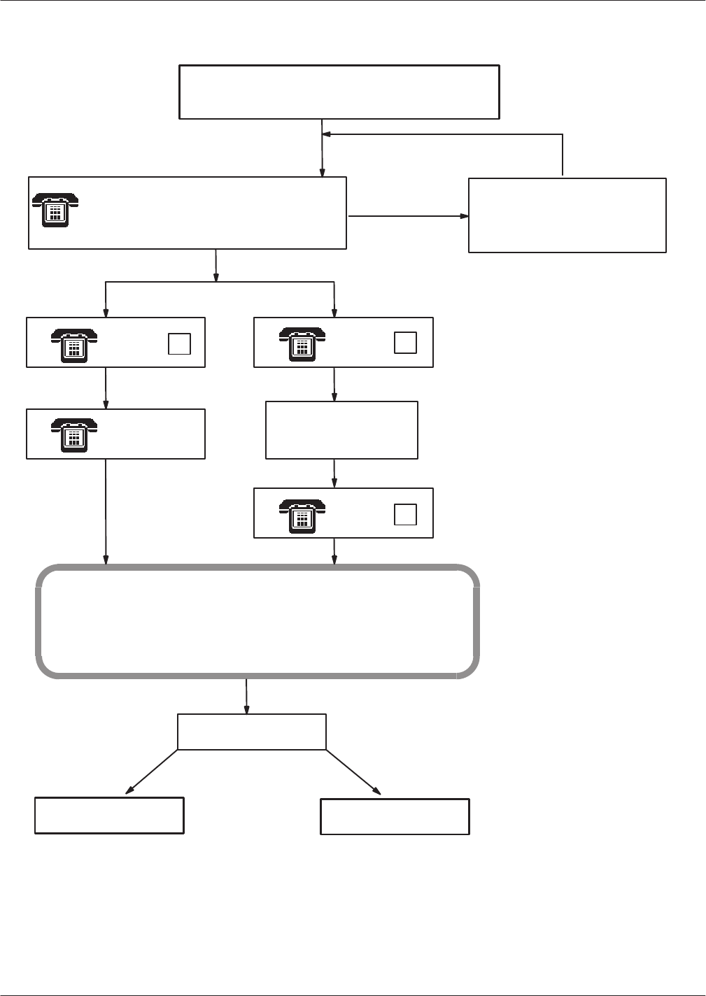
6-38
Installation and Maintenance
Volume
Octel Overture 200/300 Serenade 3.0
PB60014–01
Figure 6-1
Alarm T
est Flow
@L H
FRI MM/DD HH:MM:SS YYYY SYSTEM NAME ID:XXX S/X:XXX PBX:XXX
CLEARED: MM/DD HH:MM
***ALARM HAS BEEN GIVEN***
TABLE IS EMPTY
Callout feature tested or
@C H
PRESS PRESS
PRESS
*#
#
Goodbye
CONNECT
Modem and Terminal
DISCONNECT
@
TE A
Acknowledged
Stop call
Logon for
remote access
Line beeps" for up
to 3 minutes
List Hardware
Error Table
Clear Hardware Error Table
Beep, beep, beep. This is an alarm from
number 123. Error Type O has occurred. Press
star to confirm or press pound for modem
access."
Call disconnects after 1 minute.
Message server retries call every 10
minutes, until acknowledged.
Alarm Callout enabled
Not
Acknowledged
Message server calls string entered in System Parameter 31

Commands 6-39
Octel Overture 200/300 Serenade 3.0
PB60014–01
System Forwarding
The
forwarding string entered in System Parameter 45 — SYSTEM-RELOAD FOR
W
ARD STRING, is
automatically sent if the Octel Overture 200/300 reloads for any reason. During this time, calls are not
accepted for several minutes, while an automatic check is performed on the database. If forwarding
strings are not set up, incoming calls receive a ring-no-answer until the message server is ready
. When
forwarding strings are set up correctly
, the PBX forwards all incoming calls to an operator or attendant
for handling until the message server is ready to receive calls. The following describes the procedure for
testing this feature.
Either the
COURTESY DOWN
(CD x y z)
command, or the
TEST CHANNEL 1
(TE C 1 X Y)
command
to test the forward feature. Y
ou can specify a specific port or range of ports. This command
causes each port to attempt the forward.
When successful, the following message is displayed:
Port #1 Forwarded
.
.
.
All Requested Ports Forwarded
If
only one port is specified, the Octel Overture 200/300 attempts to forward only that port. If a range is
specified, the message server attempts to forward all ports in the range. If no port is specified, the
message server tries to forward all ports. If a port is successfully forwarded, it is left in the forwarded
state. If a port fails to complete the forwarding, it is left in the NDT state. The Octel Overture 200/300
continues to try to forward all ports specified, until successful or until you press
. T
o review the
port status, use the
P S
command. T
o cancel forwarding, run the System Initialization test, as described
in the following section.
For additional information about using the
CD x y z
command, refer to the System Service Mode
Commands, Courtesy Up/Courtesy Down, section.
System Initialization
When
the Octel Overture 200/300 has reloaded and is ready to handle calls, an initialization sequence
automatically takes place. First, the message server attempts PBX initialization (System Parameter 33 —
PBX INITIALIZE CODE), then attempts the cancel forward string (System Parameter 46 —
SYSTEM-RELOAD CANCEL FOR
W
ARD-STRING), for each port in turn. When a port fails to
complete the initialization or the cancel forward, the port is left in the NDT state. The message server
attempts to initialize a port every 10 seconds.
Use either the
COURTESY UP
(CU x y z)
command or the
TEST CHANNEL 2
(TE C 1 x y)
command
to test this feature. You can specify a specific port or range of ports. This command causes the
server to attempt initialization and cancel forward for each port in turn.
When the initialization is successful, the following message is displayed:
Port #1 Initialized
.
.
.
All Requested Ports Initialized

6-40
Installation and Maintenance
Volume
Octel Overture 200/300 Serenade 3.0
PB60014–01
If
only one port is specified, the Octel Overture 200/300 tries to initialize and cancel forwarding for only
the port specified. If a range is specified, the message server tries to initialize and cancel forwarding for
all ports in the range. If no port is specified, the message server tries to initialize and cancel forwarding
for all ports. If a port is successfully initialized and forwarding is canceled, it goes to the IDL state. If a
port fails to complete either the initialization or the forwarding, the status remains NDT
.
For additional information about using the
CU x y z
command, refer to the System Service Mode
Commands, Courtesy Up/Courtesy Down, section.
System
Status
Use
the
TEST STATUS
command to check the message server status for d.c. voltages and the
temperature. At the @ prompt, type
TE S
If
d.c. voltages and the temperature are within acceptable ranges, the Octel Overture 200/300 responds
with the following:
SYSTEM STATUS TESTED OK.
If
d.c. voltages and the temperature are out of range, the Octel Overture 200/300 responds with the
following:
ERROR DETECTED. SEE HARDWARE ERROR TABLE.
List
Features
Use
the
LIST FEATURES
command to list the following:
Optional feature packages installed
Number of installed, authorized, and used ports, mailboxes, and disk-storage hours
Maximum number of drives, ports, and languages allowed in the message server
At the @ prompt, type
L F

Commands 6-41
Octel Overture 200/300 Serenade 3.0
PB60014–01
@L F
–––––––––––––––– SYSTEM SOFTWARE RELEASE S.x.x.x (MM/DD/YY) ––––––––––––––––
DAY MM/DD HH:MM:SS YYYY SYSTEMNAME ID:XXX S/N:XXXXXX PBX:23
MODEL TYPE: OCTEL OVERTURE 300
SERIAL NUMBER: 200003
FEATURE PACKAGES:
SW–30001 SW–30003 SW–30004 SW–30007 SW–30008 SW–30009 SW–30015
SW–30019 SW–30020 SW–30021 SW–30022 SW–30023 SW–30024 SW–30026 SW–30027
SW–30028 SW–30029 SW–30030 SW–30031 SW–30032 SW–30034 SW–30049 SW–30050
SW–30051 SW–30052 SW–30053 SW–30055 SW–30056 SW–30057
––––––––––––––––––––––––––––––––––––––––––––––––––––––––––––––
Authorized Used Unused Installed
–––––––––––––––––––––––––––––––––––––––––––––––––––––
Ports : Analog –– 0 0 0
Fax –– 8 0 8
DSP 16 8 8 16
PIC 24 20 4 24
MBXs : Voice 900 678 222 10000
Non–Voice 9100 0 9100 10000
VMB 250 144 106 900
Fax 640 507 133 10000
Storage : Hours 100 58 42 106
––––––––––––––––––––––––––––––––––––––––––––––––––––––––––––––
MAXIMUM NUMBER OF DRIVES: 6
MAXIMUM NUMBER OF PORTS: 64
MAXIMUM NUMBER OF SCHEDULE TABLE ENTRIES: 8
NUMBER OF LANGUAGES: 2
@
The
LIST FEATURE
screen fields are described as follows:
Shows the model number that is configured.
Shows the serial number entered during INST
ALL.
Lists the feature packages that are installed, including standard and optional
features.
Information for Ports, MBXs and Storage are divided into columns marked
Authorized, Used, Unused, and Installed.
The
Authorized
column shows the total number purchased.
The
Used
column shows the number configured or used. This number can be
as high as the number authorized.
The
Unused
column shows the number available to be used. (The total
number authorized minus the total number used.)
The
Installed
column shows the total capacity of the message server for
specific port or mailbox types and storage hours. W
ith Capacity on Demand
(COD), a feature can be installed, but not authorized. For ports, this number is
the number of ports present on the cards physically installed in the message
server
. For mailboxes, this indicates the maximum number of mailboxes that
this message server supports.
Model Type
Serial Number
Feature
Packages
Ports, Mbx, and
Storage
Information

6-42
Installation and Maintenance
Volume
Octel Overture 200/300 Serenade 3.0
PB60014–01
This
rows lists the types of ports installed.
The
Analog
row refers to the 4- and 8-port LIC. If the 4- and 8-port line cards
are not controlled by Capacity on Demand (COD), the Authorized column is
empty.
The
Fax
row is the number of fax-application-processor channels installed. If
the fax card is not controlled by COD, the Authorized column is empty
.
The fax capability for a mailbox is controlled by COD.
The
DSP
row shows the number of DLC16 and ILC12 ports authorized, used,
and installed.
The PIC row shows the number of PBX integration card ports authorized, used,
and installed.
This row lists the types of mailboxes installed.
The
Voice
row is the number of authorized, used, and installed mailboxes
used for messaging.
The
Non-Voice
row shows the number of mailboxes designated for
applications use. These are mailboxes assigned Attribute 26 — MA
Y NOT
USE INTERNAL MESSAGING FEA
TURES. For non-voice mailboxes, the
value in the Authorized field is the installed number of mailboxes less the
number of used voice mailboxes.
The
VMB
row is the number of authorized, used, and installed V
isual Mailbox
licenses. The value in the Installed field is equal to the value for authorized
voice mailboxes.
The
Fax
row is the number of authorized, used, and installed fax mailbox
licenses. The value in the Installed field is equal to the value for installed voice
mailboxes.
This row lists the number of message storage hours authorized, used and installed.
The value in the Authorized field is the number of hours purchased for COD drives
added to the total hours on non-COD drives, not including the message server
overhead. The Used field indicates the total number of hours actually used to store
messages, names, greetings, redundant copies and network names. The Installed
field is the actual physical capacity of all drives in the message server
.
The hours used for message server overhead are not included in either the
Used or Installed values. If all drives were either non-COD drives or fully
authorized COD drives, Installed and Authorized would be the same.
Shows the maximum number of disk-drive slots possible for the message server
.
Shows the maximum number of ports possible for the message server
, including
analog
, DSP
, PIC, and fax.
Shows the maximum number of entries allowed in SCHEDULE T
able entries. The
maximum number is 8.
Lists the number of languages installed.
Ports
Mailboxes
Storage
Maximum
Number of
Drives
Maximum
Number of Ports
Maximum
Number of
Schedule Table
Entries
Number of
Languages

Commands 6-43
Octel Overture 200/300 Serenade 3.0
PB60014–01
6.3 APPLICATION
DELA
YS
Application
delays are timing values set in the Octel Overture 200/300. Some of these delays are used to
detect the tone cadence that the PBX provides to the Octel Overture 200/300. The tone cadence indicates
a specific call condition; for example, a ringback tone indicates that the called extension is ringing, and a
busy tone indicates that the called extension is busy
.
When a PBX type is selected for System Parameter 3 — PBX TYPE/PBX MODEL, the default values
are set to match the tone cadence of the selected PBX. If the PBX type is not in the list provided by
System Parameter 3, select the PBX type
OTHER
. Because the tone-cadence values in that situation are
not known, the Octel Overture 200/300 defaults to generic/industry-standard values; for example, a
1-second-on/3-second-of
f ring cadence, a 500-ms-on/500-ms-of
f busy cadence, and a 250-ms-on/of
f for a
fast-busy cadence. These values could need to be changed to work correctly with your PBX when
OTHER
has been selected.
If the Octel Overture 200/300 can already detect ringback, slow-busy
, fast-busy
, and if configured, double
interrupted ringback, the application delay indexes do not need to be modified. However
, if the Octel
Overture 200/300 detects an answer condition while monitoring single or double interrupted-ringback,
slow-busy
, or fast-busy tones, you must modify the application-delay indexes. The application-delay indexes
that can be modified are described in the How to Modify Application Delays section in this chapter
.
How T
ones Are Recognized
When
the Octel Overture 200/300 screens a call, it is looking for single- or double-interrupted ringback,
slow-busy
, or fast-busy tones. T
o process the call transfer
, the Octel Overture 200/300 refers to
application-delay indexes 49 through 52. These indexes show the maximum and minimum ON/OFF
periods for any tone.
If the tone cadence detected does not comply with these delays, the Octel Overture 200/300 determines
that the tone is not a single or double interrupted ringback, slow busy
, or fast busy and that the call has
been answered. If this occurs, the message server completes the call transfer
. In a screen display of the
Print T
one (PR
T) and List T
race, an answer condition is indicated.
If the tone cadence is within the values set for delays 49 through 52, the Octel Overture 200/300 then
compares the tone cadence with application-delay indexes 53 through 76 for single interrupted ringback,
double interrupted ringback, slow-busy and fast-busy delays, to determine what the condition is. If it does
not comply with any of these delays, it is assumed that the call has been answered and the Octel Overture
200/300 completes the transfer. Figure 5-2 shows the sequence that the Octel Overture 200/300 follows to
screen calls.
If the PBX provides double interrupted ringback when an internal extension calls another internal
extension, System Parameter 26 — DOUBLE-INTERRUPTED RINGBACK, is set to YES. The
Octel Overture 200/300 looks for a double interrupted ringback versus a single interrupted
ringback when calling an extension.
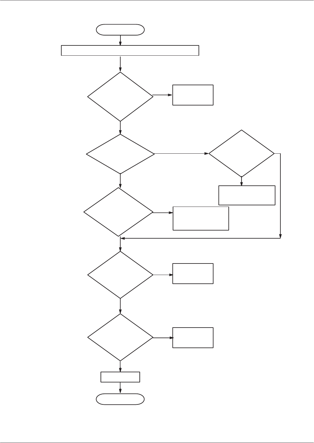
6-44
Installation and Maintenance
Volume
Octel Overture 200/300 Serenade 3.0
PB60014–01
The phone rings,
monitor ringback (Infor
-
mation T
able Index 7)
Figure 6-2 Sequence Used by the Octel
Overture 200/300
T
o Screen Calls
Start
of T
ransfer
Dial extension digits and begin looking for tone patterns
Do the tones
comply with ranges
set by delays
49, 50, 51,
or 52?
NO
Do the tones
comply with ranges
set by delays
53, 54, 55,
or 56?
Do the
tones comply
with Indexes 61, 62,
63, 64, 65,
66, 67,or
68?
Do the tones
comply with ranges
set by delays 69, 70,
71, or 72?
Do the tones
comply with ranges
set by delays
73, 74, 75,
or 76?
Slow Busy
Fast Busy
Answer
Pull
call back.
Speak
“... is in
-
valid . . . ”
Is System
Parameter 26
set to YES?
Pull call back.
Speak
“ . . . is
busy...”
The call is
considered
answered
The phone rings,
monitor
ringback (Infor
-
mation
T
able Index 7)
End
NO
NO
NO
NO

Commands 6-45
Octel Overture 200/300 Serenade 3.0
PB60014–01
How To Modify Application Delays
You
should only modify those application-delay indexes for PBX tones that fail. Before modifying an
application-delay index, use the
PRT (PRINT
TONE
) command and COS Attribute 70 — MEASURE
PBX T
ONES, to determine the correct timing value. Use the following steps:
1.
Assign COS Attribute 70 to a test mailbox that has an extension number for a telephone set located
near the terminal.
When a mailbox with COS Attribute 70 is called, the Octel Overture 200/300 dials the extension
number
, stays on line for 10 tone changes, and then hangs up. During this call, you can determine the
tone cadence of the PBX.
The extension called should
not
be set to forward on ring-no-answer
, busy
, or fast busy
. Other
features, such as camp-on, must be disabled. This could give a false tone cadence.
2.
Select an
Octel Overture 200/300 port and at the @ prompt, type
PRT x
For this command,
x
is the port number to be used.
3.
Call that port’
s extension number
.
4.
When the message server answers, dial the test mailbox number
.
The
PRT
command monitors and displays the DTMF tones dialed by the caller, the DTMF tones
dialed by the Octel Overture 200/300, and the call-progress tones from the PBX to the terminal. This
command is a real-time command and can be initiated on only one port at a time. The information is
not stored.
If the tones do not show on the screen when the
PRT
command displays the DTMF events, at
the @ prompt, type
C S
5.
Repeat steps 2 through 4. If executing the
C S
command does not help, contact your technical
support center
.
The
PRT
command should be initiated for any call condition that fails, such as when the message
server calls an extension that is sending a ringback but the message server detects an answer
condition.
The following example displays tone information when the Octel Overture 200/300 screens a call to
a ring-no-answer extension that fails. Refer to the Miscellaneous Commands section in this chapter
for a list of Print T
one output types.

6-46
Installation and Maintenance
Volume
Octel Overture 200/300 Serenade 3.0
PB60014–01
@PRT 1
IN–2
IN–2
IN–0
FLASH
EXPECT DIAL TONE
420 MS
T ON
600 MS
DIAL TONE
DIAL–2
DIAL–2
DIAL–0
2620 MS
T ON
1000 MS
T OFF
2880 MS
T ON
980 MS
T OFF
2920 MS
T ON
790 MS
ANSWER
The
Octel Overture 200/300
monitors
tones for dial tone.
The caller enters DTMF digits.
Octel Overture 200/300
dials
DTMF digits.
Octel Overture 200/300
ignores
the first tone change.
Octel Overture 200/300 monitors call progress tones from
the
PBX
to
determine the status of the called extension.
Failure:
Octel
Overture 200/300
detects
an answer
condition
because
one of the tones from the
PBX
does
not conform to
delays in the Application Delay T
able.
Dial tone is detected.
6. Review
the
PRT
display to determine the tone cadence of the tone being monitored. Refer to the
How to Modify Application Delays section in this chapter to find the application-delay indexes that
refer to the error received.
7.
Enter UPDA
TE to list the current values in the Application Delay T
able; at the dot (.) prompt, type
L APP
8.
Create a tone timing diagram to help determine the tone cadence.
The tone values from the
PRT
display and the current application-delay values listed in the
Application Delay T
able can be included in the diagram to determine how much an individual tone
needs to be modified.
For the preceding
PRT
example, the application-delay indexes that refer to the error received are
indexes 50 and 54. Figure 6-3 shows what the failure would look like on a tone timing diagram. Note
that the failure occurred when the PBX sent a T
ONE ON for 790 ms. The Octel Overture 200/300 was
set to expect a T
ONE ON (ringback) for no less then 800 ms and no greater than 1200 ms. This is
referred to as the “window
.” In the diagram, the window for the silence period (TONE OFF) between
rings is set to no less than 2800 ms and no greater than 3400 ms. The T
ONE OFF values are within
that window
.
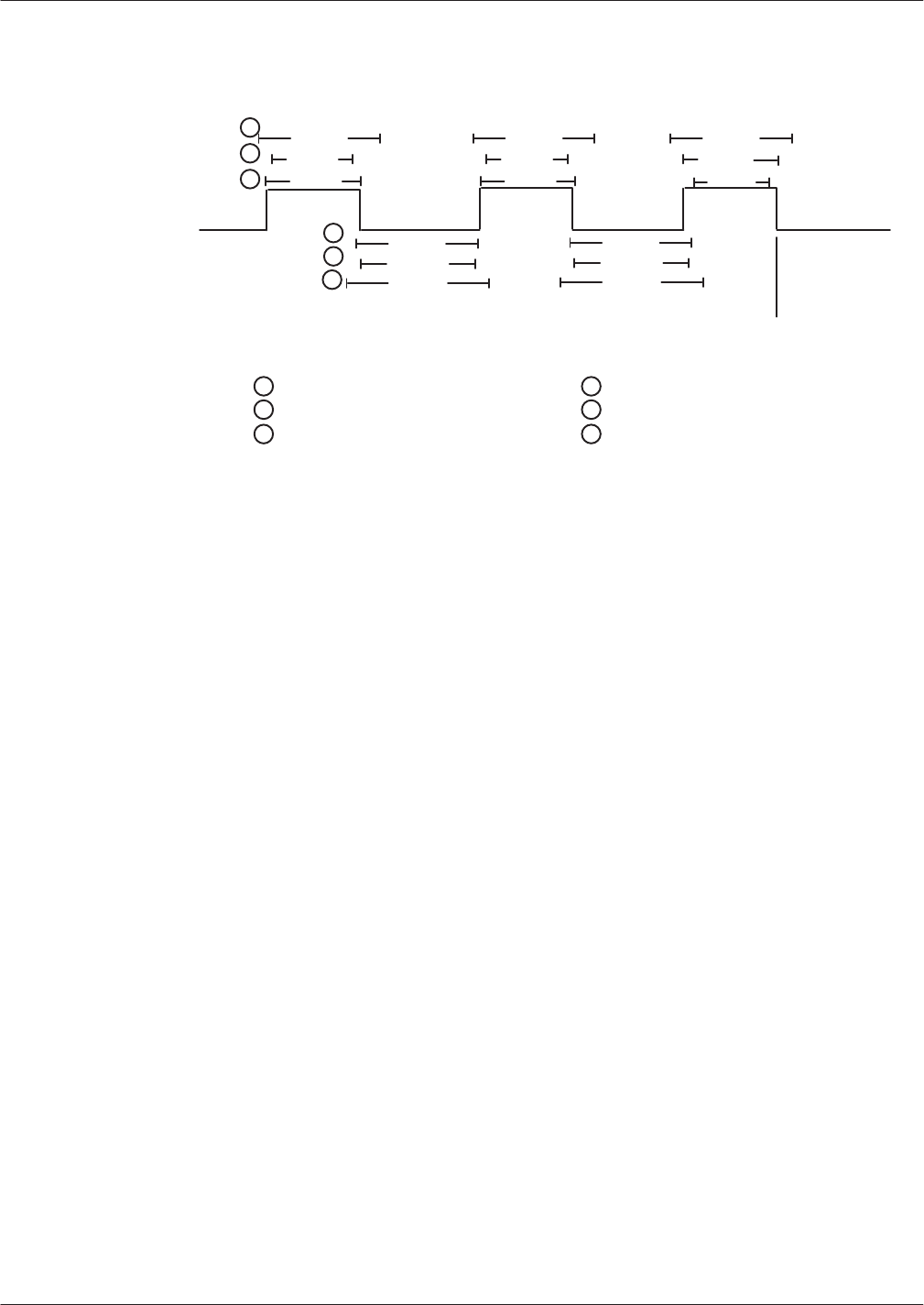
Commands 6-47
Octel Overture 200/300 Serenade 3.0
PB60014–01
Figure 6-3
Ring/No Answer T
one-T
iming Failure
PBX T
one ON
1000 ms
2880 ms
Answer Condition
800 ms
1200 ms
980 ms
800 ms
1200 ms
1200 ms
2800 ms
3400 ms
2920 ms
2800 ms
3400 ms
Maximum Tone ON (53)
1
1
Minimum Tone ON (54)
Minimum Tone OFF (56)
Maximum Tone OFF (55)Actual Time Tone ON
Actual Time Tone was OFF
800 ms
9. Modify
the required application delays.
In this case, Application Delay index 54 would be changed from 800 ms to 760 ms. Decreasing
Index 54 allows for the 790 ms TONE ON.
Index 50 must be equal to or less than Index 54.
10.
After modifying the appropriate delays, remove Attribute 70, and retest the calls that failed.
If calls still fail, repeat this procedure from step 1.
Modifiable
Application-Delay Indexes
The
application-delay indexes that can be modified at the Maintenance level while in UPDA
TE are listed
below
, with descriptions of what the delay does and how to use it.
Application
Delays for Addressing
WAIT DURING ADDRESSING TO RESOLVE DIGIT ENTERED
During addressing, Application Delay 131 causes a delay between digit entries when 0 is the
first digit of mailboxes and extensions or when local mailbox addresses overlap network
prefixes. The default delay is 2.0 seconds.
Use —
When 0 is the initial digit for mailboxes and extensions, after 0, or 00–09 are entered,
the message server waits for more digits. If no more digits are entered, the call is transferred
to the operator (0), to the Dial-by-Name directory (00), or
, in the case of a PDL address
(01–09), the address is registered.
When local mailbox addresses overlap network prefixes, the message server waits for more
digits after the local mailbox address is entered. If more digits are entered before the timeout
131

6-48
Installation and Maintenance
Volume
Octel Overture 200/300 Serenade 3.0
PB60014–01
period
expires, the address is considered to be a network address. For details about
overlapping mailbox addresses and network prefixes, refer to the
Networking
volume, Remote
Analog Networking chapter, Remote Networking Operation, Addressing for Overlapping
Mailbox Addresses, and Network Prefixes sections.
Application
Delays for Call Processing
WAIT AFTER OFF HOOK BEFORE GIVING PROMPT
Application Delay 8 causes a delay between the time the port goes of
f hook and the time the
greeting or system prompt is played.
Use —
If the PBX is slow in sending the speech paths through, it could cause greetings or
prompts to be clipped (only part of the greeting or prompt heard). Modify Application Delay
8 to delay for a longer time before the message server plays the greeting or prompt.
TIMEOUT BEFORE LOOKING FOR RINGBACK OR BUSY
After dialing an extension number
, the message server waits the amount of time specified in
Application Delay 19 before looking for a ringback, busy, or fast-busy tone.
Use —
Some PBXs send a partial ringback or busy tone before starting the ringback or
busy-tone cycle. That would cause the Octel Overture 200/300 to fail, because the partial tone
would not comply with any of the tone windows established in the Application Delay T
able.
Modify Application Delay 19 for a longer time interval.
WAIT LONGER BEFORE LOOKING FOR RINGBACK
Application Delay 87 only works in conjunction with COS Attribute 30 —
EXTENSION IS ON
ANOTHER PBX, WAIT LONGER BEFORE LOOKING AT TONES.
After dialing an extension
number
, the message server waits the amount of time specified in Application Delay 87
before looking for a ringback, busy
, or fast-busy tone.
Use —
In some PBX environments, two or more PBXs might be connected through tie lines,
so users on a local PBX could dial an extension number on a remote PBX and be routed
directly to it, without going over the public network. The ringback tone from the distant PBX
is delayed while the PBXs set up the call. W
ithout Attribute 30 and Application Delay 87, the
Octel Overture 200/300 detects the longer silence as an answer and attempts to transfer the
call, which causes a failure. This COS attribute and application-delay combination allows the
Octel Overture 200/300 to wait before looking for a ringback tone when calling certain
extensions.
Application Delays used with Enhanced DTMF In-band Integration
This
delay is used as the first delay when looking for dial tone after flash, or whenever E,
expect dial tone, is in a dialing string.
Use —
The message server uses this delay to determine if the PBX has provided dialtone after
flash or whenever E is in a dialing string. If dialtone is not received from the PBX within the
8
19
87
79

Commands 6-49
Octel Overture 200/300 Serenade 3.0
PB60014–01
duration
of this delay
, the message server flashes again for dialtone, or, in the case of dialing
strings, hangs up and tries again.
This delay may be modified in the CPT environment to account for slow CPT (for
dialtone) from the PBX.
FIRST DIGIT TIMEOUT WHILE WAITING FOR DTMF CALL RECORD
This delay value is the time the message server waits after going of
f hook for the first DTMF
digit of an enhanced DTMF in-band call record.
Use —
Some PBXs might not send DTMF call records (digits) in a timely manner
. If this
occurs, the Octel Overture 200/300 plays the default company greeting. This delay forces the
message server to wait longer for the first DTMF digit of the call record.
INTERDIGIT TIMEOUT WHILE WAITING FOR DTMF CALL RECORD
This delay is the length of time that the message server waits for subsequent DTMF digits of
an enhanced DTMF in-band call record. After the message server receives a DTMF digit of a
call record, this timer starts. If the time ends before receiving another digit, the message
server assumes that the PBX is finished sending digits. If the digits received match a Call
Record Condition in the DTMFINT T
able, the message server takes the appropriate action
(plays mailbox greeting, etc.). If the digits received
do not
match a Call Record Condition,
the message server plays the default company greeting.
Use —
If a PBX is slow in sending DTMF digits, this delay should be increased to
compensate for this.
DELAY BEFORE PLAYING PROMPT AFTER RECEIVING CALL RECORD
This delay is the time that the message server waits before playing a greeting or prompt after
receiving a complete enhanced DTMF call record.
Use
—
When the PBX sends a DTMF call record to the Octel Overture 200/300, the speech
path is not sent through to the caller
. The caller hears silence or a ringback tone. After the
PBX sends the last DTMF digit of the call record, it connects the caller and the Octel
Overture 200/300. If the PBX is slow to send the speech path through, part of the greeting or
prompt could be clipped. By extending this delay
, the message server waits longer before
playing a greeting or prompt.
This delay is used to detect Ring-No-Answer (RNA). The default for this delay is a value of
5000 msec.
Use
—
When internal calls have a value specified in Information Index T
able 7 —
NUMBER OF RINGS BEFORE EXTENSION NO ANSWER, this value multiplied by the
duration of one ring gives the time-out value for RNA. When message waiting outcalls have a
value specified in Information Index T
able 8 — NUMBER OF MESSAGE W
AITING
RINGS, this value is used to compute the time-out value for RNA.
This delay is used to detect call transferring hang-up delays. The default for this delay is a
value of 30000 msec.
110
111
112
141
142

6-50
Installation and Maintenance
Volume
Octel Overture 200/300 Serenade 3.0
PB60014–01
Use
—
When specifying the maximum time the message server waits for the call
transferring party to hang up, so that the transfer to an extension forwarded to the message
server is completed.
Application Delays for Cadence Recognition
MAXIMUM
T
ONE ON PERIOD FOR ANY TONE
This delay must be set to a value equal to the lar
gest value for any of the following delays set
in the Application Delay Table: 53, 61, 63, 69, or 73.
Use —
When the message server looks for a ringback, busy, or fast-busy tone, it uses this
delay to determine whether the TONE ON is a valid tone. If the T
ONE ON is longer than this
delay
, the message server assumes an answer condition has occurred.
MINIMUM T
ONE ON PERIOD FOR ANY TONE
This delay must be set to a value less than the value for any of the following delays set in the
Application Delay Table: 54, 62, 64, 70, or 74.
Use —
When the message server looks for a ringback, busy, or fast-busy tone, it uses this
delay to determine whether the TONE ON is a valid tone. If the T
ONE ON is less than this
delay
, the message server assumes an answer condition has occurred.
MAXIMUM TONE OFF PERIOD FOR ANY TONE
This delay must be set to a value equal to the lar
gest value for any of the following delays in
the Application Delay T
able: 55, 65, 67, 71, or 75.
Use —
When the message server looks for a ringback, busy, or fast-busy tone, it uses this
delay to determine whether the TONE OFF is a valid silence period. If the TONE OFF is
greater than this delay
, the message server assumes an answer condition has occurred.
Application delay 123 must be set to 0 for the server to wait the time specified in
application 51. See application delay 123.
MINIMUM T
ONE OFF PERIOD FOR ANY TONE
This delay must be set to a value less than the value for any of the following delays in the
Application Delay Table: 56, 66, 68, 72, or 76.
Use —
When the message server looks for a ringback, busy, or fast-busy tone, it uses this
delay to determine whether the TONE OFF is a valid silence period. If the T
ONE OFF is less
than this delay
, the message server assumes that an answer condition has occurred.
RINGBACK MAXIMUM TONE ON PERIOD
This delay is the longest delay that a T
ONE ON can be to qualify as a ringback.
Use —
The message server uses this delay to determine whether the tone cadences that it is
monitoring is a ringback. If the T
ONE ON is longer than this delay
, the message server
assumes that it is not a ringback.
49
50
51
52
53

Commands 6-51
Octel Overture 200/300 Serenade 3.0
PB60014–01
RINGBACK
MINIMUM T
ONE ON PERIOD
This delay is the shortest delay that a T
ONE ON can be to qualify as a ringback.
Use —
The message server uses this delay to determine whether the tone cadences that it is
monitoring is a ringback. If the T
ONE ON is shorter than this delay
, the message server
assumes that it is not a ringback.
RINGBACK MAXIMUM TONE OFF PERIOD
This delay is the longest delay that a T
ONE OFF can be to qualify as a ringback.
Use —
The message server uses this delay to determine whether the tone cadences that it is
monitoring is a ringback. If the T
ONE OFF is longer than this delay
, the message server
assumes that it is not a ringback.
RINGBACK MINIMUM TONE OFF PERIOD
This delay is the shortest delay that a T
ONE OFF can be to qualify as a ringback.
Use —
The message server uses this delay to determine whether the tone cadences that it is
monitoring is a ringback. If the T
ONE OFF is shorter than this delay
, the message server
assumes that it is not a ringback.
This delay
should only be modified
when using CPT
-DTMF integration and must be set to 0
or a value greater than application delay 51.
Use —
If application delay 123 is 0, the server waits for the amount of time specified by
application delay 51 for the first T
ONE ON. If application delay 123 is non-zero, after dialing
out digits for an outcall, the server waits this amount of time for the FIRST TONE ON
condition. If no T
ONE ON occurs in this specified time, the server assumes the call was
answered.
Application Delay indexes 61 through 68 are used only if System Parameter 26 is set to YES.
DOUBLE INTERRUPTED RINGBACK MAXIMUM TONE ON LONG PERIOD
This delay is the longest delay that a T
ONE ON, of the long T
ONE ON period, can be to
qualify as a double interrupted ringback.
Use —
The message server uses this delay to determine whether the tone cadences that it is
monitoring is a double interrupted ringback. If the T
ONE ON is longer than this delay, the
message server assumes that it is not a double interrupted ringback.
DOUBLE INTERRUPTED RINGBACK MINIMUM TONE ON LONG PERIOD
This delay is the shortest delay that a T
ONE ON, of the long T
ONE ON period, can be to
qualify as a double interrupted ringback.
Use —
The message server uses this delay to determine whether the tone cadences that is
monitoring is a double interrupted ringback. If the T
ONE ON is shorter than this delay, the
message server assumes that it is not a double interrupted ringback.
54
55
56
123
61
62

6-52
Installation and Maintenance
Volume
Octel Overture 200/300 Serenade 3.0
PB60014–01
DOUBLE INTERRUPTED RINGBACK MAXIMUM TONE ON SHORT PERIOD
This delay is the longest delay that a T
ONE ON, of the short T
ONE ON period, can be to
qualify as a double interrupted ringback.
Use —
The message server uses this delay to determine whether the tone cadence that it is
monitoring is a double interrupted ringback. If the T
ONE ON is longer than this delay, the
message server assumes that it is not a double interrupted ringback.
DOUBLE INTERRUPTED RINGBACK MINIMUM TONE ON SHORT PERIOD
This delay is the shortest delay that a T
ONE ON, of the short T
ONE ON period, can be to
qualify as a double interrupted ringback.
Use —
The message server uses this delay to determine whether the tone cadences that it is
monitoring is a double interrupted ringback. If the T
ONE ON is shorter than this delay, the
message server assumes that it is not a double interrupted ringback.
DOUBLE INTERRUPTED RINGBACK MAXIMUM TONE OFF LONG PERIOD
This delay is the longest delay that a T
ONE OFF
, of the long T
ONE OFF period, can be to
qualify as a double interrupted ringback.
Use —
The message server uses this delay to determine whether the tone cadences that it is
monitoring is a double interrupted ringback. If the T
ONE OFF is longer than this delay
, the
message server assumes that it is not a double interrupted ringback.
DOUBLE INTERRUPTED RINGBACK MINIMUM TONE OFF LONG PERIOD
This delay is the shortest delay that a T
ONE OFF
, of the long T
ONE OFF period, can be to
qualify as a double interrupted ringback.
Use —
The message server uses this delay to determine whether the tone cadences that it is
monitoring is a double interrupted ringback. If the T
ONE OFF is shorter than this delay
, the
message server assumes that it is not a double interrupted ringback.
DOUBLE INTERRUPTED RINGBACK MAXIMUM TONE OFF SHORT PERIOD
This delay is the longest delay that a T
ONE OFF, of the short T
ONE OFF period, can be to
qualify as a double interrupted ringback.
Use —
The message server uses this delay to determine whether the tone cadences that it is
monitoring is a double interrupted ringback. If the T
ONE OFF is longer than this delay
, the
message server assumes that it is not a double interrupted ringback.
DOUBLE INTERRUPTED RINGBACK MINIMUM TONE OFF SHORT PERIOD
This delay is the shortest delay that a T
ONE OFF, of the short T
ONE OFF period, can be to
qualify as a double interrupted ringback.
Use —
The message server uses this delay to determine whether the tone cadences that it is
monitoring is double interrupted ringback. If the T
ONE OFF is shorter than this delay
, the
message server assumes that it is not a double interrupted ringback.
63
64
65
66
67
68

Commands 6-53
Octel Overture 200/300 Serenade 3.0
PB60014–01
SLOW BUSY MAXIMUM TONE ON PERIOD
This delay is the longest delay that a TONE ON can be to qualify as a slow-busy tone.
Use —
The message server uses this delay to determine whether the tone cadences that it is
monitoring is a slow-busy tone. If the T
ONE ON is longer than this delay
, the message server
assumes that it is not a slow-busy tone.
SLOW BUSY MINIMUM TONE ON PERIOD
This delay is the shortest delay that a TONE ON can be to qualify as a slow-busy tone.
Use —
The message server uses this delay to determine whether the tone cadences that it is
monitoring is a slow-busy tone. If the T
ONE ON is shorter than this delay
, the message server
assumes that it is not a slow-busy tone.
SLOW BUSY MAXIMUM TONE OFF PERIOD
This delay is the longest delay that a T
ONE OFF can be to qualify as a slow-busy tone.
Use —
The message server uses this delay to determine whether the tone cadences that it is
monitoring is a slow-busy tone. If the T
ONE OFF is longer than this delay
, the message server
assumes that it is not a slow-busy tone.
SLOW BUSY MINIMUM TONE OFF PERIOD
This delay is the shortest delay that a T
ONE OFF can be to qualify as a slow-busy tone.
Use —
The message server uses this delay to determine whether the tone cadences that it is
monitoring is a slow-busy tone. If the T
ONE OFF is shorter than this delay
, the message
server assumes that it is not a slow-busy tone.
FAST BUSY MAXIMUM TONE ON PERIOD
This delay is the longest delay that a T
ONE ON can be to qualify as a fast-busy tone.
Use —
The message server uses this delay to determine whether the tone cadences that it is
monitoring is a fast-busy tone. If the T
ONE ON is longer than this delay
, the message server
assumes that it is not a fast-busy tone.
FAST BUSY MINIMUM TONE ON PERIOD
This delay is the shortest delay that a T
ONE ON can be to qualify as a fast-busy tone.
Use —
The message server uses this delay to determine whether the tone cadences that it is
monitoring is a fast-busy tone. If the T
ONE ON is shorter than this delay
, the message server
assumes that it is not a fast-busy tone.
FAST BUSY MAXIMUM TONE OFF PERIOD
This delay is the longest delay that a T
ONE OFF can be to qualify as a fast-busy tone.
Use —
The message server uses this delay to determine whether the tone cadences that it is
monitoring is a fast-busy tone. If the T
ONE OFF is longer than this delay
, the message server
assumes that it is not a fast-busy tone.
69
70
71
72
73
74
75

6-54
Installation and Maintenance
Volume
Octel Overture 200/300 Serenade 3.0
PB60014–01
FAST BUSY MINIMUM TONE OFF PERIOD
This delay is the shortest delay that a T
ONE OFF can be to qualify as a fast-busy tone.
Use —
The message server uses this delay to determine whether the tone cadences that it is
monitoring is a fast-busy tone. If the T
ONE OFF is shorter than this delay
, the message server
assumes that it is not a fast-busy tone.
Coordinate the following application-delay indexes for cadence recognition. Refer to T
able 6-3.
Set index 49 to a value equal to the largest value for any of the following delay indexes: 53, 61, 63,
69, or 71.
Set index 50 to a value less than the value for any of the following delay indexes: 54, 62, 64, 70, or 74.
Set index 51 to a value equal to the largest value for any of the following delay indexes: 55, 65, 67,
71, or 75.
Set index 52 to a value less than the value for any of the following delay indexes: 56, 66, 68, 72, or 76.
Table 6-3
Application Delays for Cadence Recognition, for Determining T
one On/Tone Off
T
ONE EVENT
Maximum
Tone On Minimum
Tone On Maximum
Tone Off Minimum
Tone Off
Single
Interrupt Ringback
Index 53 Index 54 Index 55 Index 56
Max/Min
Acceptable T
one Ranges
Index 49 Index 50 Index 51 Index 52
Double
Interrupt Ringback, long periods
Index 61 Index 62 Index 65 Index 66
Double
Interrupt Ringback, short periods
Index 63 Index 64 Index 67 Index 68
Slow
Busy
Index 69 Index 70 Index 71 Index 72
Fast
Busy
Index 73 Index 74 Index 75 Index 76
Using
UPDA
TE to Modify Application Delays
You
can use UPDA
TE to modify specific application delays. When you modify an application-delay
index, enter the new value in milliseconds, rounded to the nearest 20 ms.
Use the UPDA
TE program as follows:
List the current values in the Application Delay T
able
Modify the values
List Command
Use
the
LIST
command to list the current values in the Application Delay T
able. The message server
prompts for an individual delay
. Enter the application-delay index to be listed.
T
o list all application delay indexes, press
. The following is an example of the Application Delay
Table.
76
.L APP

Commands 6-55
Octel Overture 200/300 Serenade 3.0
PB60014–01
.L APP
LST:
APPLICATION DELAY TABLE
INDEX DELAY (msec.)
00
1 7000
2 5000
3 500
4 3000
5 1200
6 1000
7 30000
8 1600
.
.
.
.
251 0
252 0
253 0
254 0
255 0
Modify Command
Use
the
MODIFY
command to change application delays. The message server prompts for the
application-delay index to be modified. Refer to the Modifiable Application–Delay Indexes section in
this chapter; only the delays that are listed can be modified at the Maintenance level. Enter the
application-delay index number
. T
ype the new value, and press
. The message server displays the
new value.
The delay values are entered in milliseconds and rounded to the nearest 20 ms value.
The following is an example of Application Delay Index 8 being modified to 1000 ms (1 second).
.M APP
Enter APPLICATION DELAY index.
MOD:8
Enter new value (in MILLISECONDS) for APP DELAY 8.
Note: Will be rounded to the nearest 20 MSEC.
(0–1310700 MSEC,
(0
means Infinite, empty line = 800 )
MOD:1000
DELAY set to 1000 MSEC.
Caution!
Changing
an Application Delay from a nonzero value
to zero should
never
be done. A zero value sets an
infinite timeout that could result in permanently
locking up a port.
.M APP

6-56
Installation and Maintenance
Volume
Octel Overture 200/300 Serenade 3.0
PB60014–01
6.4 MESSAGE
BLOCK AND MESSAGE PURGE
Voice
and fax messages for the Octel Overture 200/300 can be marked as unplayable with the
MBLOCK
message block command. Messages can be deleted on a mailbox-by-mailbox basis or from every mailbox
in the message server with the
MPURGE
message pur
ge command.
T
o block or pur
ge a message, the message header number must be identified. T
o determine the message
header number
, use either the
L M [mailbox number] M
command to list mailbox message
information for a specific mailbox, or the
L T
(list trace) command if only the approximate time of the
message is known. Refer to the Mailbox Configuration Status section in this chapter
, for more
information about listing mailbox messages.
Marking
a Message Unplayable
Messages
that are recorded and sent can be blocked from being played by the message recipients.
Blocking a message makes the message unplayable.
Making a message unplayable has no immediate ef
fect on that message if it is already being played.
However
, it prevents a mailbox holder from starting to play or to replay the message after it is blocked. If
a mailbox holder does attempt to play an unplayable message, the creator
’
s name is played. The status
prompt plays, followed by
“This message has been marked unplayable by the system administrator
.
Please erase.”
This same prompt is heard if the message is a fax message that the user is trying to print by entering
. The normal fax-message menu, with options to print the fax, is not played. The auto-print feature
is suppressed for fax messages marked unplayable
.
If a message is marked for delivery to a remote mailbox but has not been sent, this same prompt is sent
over the network instead of the message. Messages already sent over the network are not deleted or
blocked by the
MPURGE
and
MBLOCK
commands.
The mailbox holder might hear silence rather than the preceding prompt, if the following occurs:
The
MBLOCK
command is entered at the same time the message is played for a local user or sent
over the network.
A mailbox holder has forwarded the message using the future-delivery option and then listens to the
message while it is still in the mailbox.
T
o block a message from being played, at the @ prompt, type
MBLOCK x y
In this command,
x
is message header number
, and
y
indicates that the message is to be blocked.
The message server responds with a request to confirm this command.
MAKE MESSAGE 5001 UNPLAYABLE
ARE YOU SURE YOU WANT TO DO THIS? Y
MESSAGE 5001 MADE UNPLAYABLE

Commands 6-57
Octel Overture 200/300 Serenade 3.0
PB60014–01
A
message that is marked as unplayable can be unmarked. T
o unblock a message so that it can be played
again, at the @ prompt, type
MBLOCK x n
In this command,
x
is message header number
, and
n
indicates that the message is to be unblocked. The
message server responds with a request to confirm this command.
MAKE MESSAGE 5001 PLAYABLE
ARE YOU SURE YOU WANT TO DO THIS? Y
MESSAGE 5001 MADE PLAYABLE
The
messages server executes the
MBLOCK
command without checking whether the message is currently
playable or not.
Blocked messages are not automatically deleted from the message server
. The space and message header
will be available for reuse whenever the message server has been restarted. When a message is blocked,
the message is flagged as
UNPLAY.
@MBLOCK 6941Y
MAKE MESSAGE 6941 UNPLAYABLE
ARE YOU SURE YOU WANT TO DO THIS? Y
MESSAGE 6941 MADE UNPLAYABLE
@L HE 6941
CREATOR MAILBOX NUMBER 8048
EXTENSION MESSAGE NUMBER:0000
.
.
.
.
.
.
FLAGS:UNPLAY
ADDRESSES:
The
Call Processing Trace shows that the message has been made unplayable for all mailboxes for which
the
M PURGE
command was used.
@L T
.
.
.
.SELECT TRACE TO BE LISTED. (1–7), EMPTY LINE = EXIT).
:2
Enter mailbox (Empty line = ALL)
:4585
Enter start time : Year Month Day Hour Minute or C
(continuous)
:97 12 10 16 00
TIME 12/10/97 16:00
MSG 6941 MADE UNPLAYABLE
.
.

6-58
Installation and Maintenance
Volume
Octel Overture 200/300 Serenade 3.0
PB60014–01
MPURGE Command Usage
A
message that has been recorded and sent can be deleted from one or all mailboxes in the message
server.
From
all
mailboxes, the
MPURGE
command first initiates an
MBLOCK
command so that, while the
message server is searching each mailbox for an occurrence of the message, mailbox holders cannot play
that message.
The search that occurs after the
MBLOCK
command is issued can take some time to be executed. For
example, on a message server with 1,200 mailboxes, the search takes approximately 1/2 hour
. Also,
seconds or even minutes might elapse between the display of the next “mailbox scheduled for deletion”
prompt. When the search has been completed, because the
MBLOCK
command is issued by the message
server before beginning the message-pur
ge search, the message continues to use the header assigned to it,
and it remains on the disk until the message server is restarted.
When the
MPURGE
command is issued to delete a message from
an individual
mailbox, the
MBLOCK
command is not evoked. The message is deleted from the mailbox specified. When issued for a particular
mailbox, the
MPURGE
command is quick to be executed. If a message was sent, for example, to three
mailboxes and pur
ged one mailbox at a time from each of the three, after the final deletion, the message
is deleted from the disk and the header is made available for reuse.
Whether for a single mailbox or for all mailboxes, when the
MPURGE
command is issued to request that a
message be deleted, if the mailbox holder is logged on, the request to delete is queued, and the deletion
occurs after the mailbox holder logs of
f.
If the message server is restarted while deletion requests are queued, those queued requests are lost.
However
, the message remains unplayable if it has been blocked (explicitly by
MBLOCK
or implicitly by
the all-mailbox
MPURGE
command). T
o verify that messages have been deleted before restarting the
message server
, check the trace log.
MPURGE Command for All Mailboxes
To
delete a message from every mailbox in the message server
, at the @ prompt, type
MPURGE x
In this command,
x
is the message-header number
.
DELETE MESSAGE 5001 FROM ALL MAILBOXES
ARE YOU SURE YOU WANT TO DO THIS? Y
MESSAGE 5001 SCHEDULED FOR DELETION FROM MAILBOX 2021
MESSAGE 5001 SCHEDULED FOR DELETION FROM MAILBOX 2022
.
.
@
The
message server searches all mailboxes for the message to be deleted before returning to the @ prompt.
As it searches, the following prompt is displayed each time there is an occurrence of the message:
MESSAGE xxx SCHEDULED FOR DELETION FROM MAILBOX yyy.

Commands 6-59
Octel Overture 200/300 Serenade 3.0
PB60014–01
The
command can be canceled by entering
. The execution pauses, and the following message is
printed:
ABORT MPURGE (AND LEAVE MESSAGE UNPLAYABLE) .
ARE YOU SURE YOU WANT TO DO THIS? Y
@
Enter
Y
to abort the message pur
ge. If the message pur
ge is aborted, all messages that have already been
queued for deletion are deleted.
MPURGE Command for Message-by-Message Use
To
delete a message from one mailbox, at the @ prompt, type
MPURGE x z
In this command,
x
is the message header number and
z
is the mailbox number
.
Before checking whether the message is actually present in the mailbox, the Octel Overture 200/300
requests confirmation before deleting a message from the mailbox. For example, when a message is to be
deleted from one mailbox, the message server responds with the following:
DELETE MESSAGE 5001 FROM MAILBOX 2022
ARE YOU SURE YOU WANT TO DO THIS? Y
@
If
an original recipient has forwarded the message, the forwarded instance of the message is not
deleted with the
MPURGE x y
command. However
, if a message is deleted from
every
mailbox
by the
MPURGE x
command, the message, but not the forwarding comments, is blocked and
cannot play
.
If the message should be restricted from all delivery
, two options for removing the message are available:
Use
MPURGE
to delete the message from all mailboxes. If the message server is lar
ge, this could take
some time. The message could be heard by some users before the command to delete it from their
mailboxes is issued.
Do an
MBLOCK
and then a single-mailbox
MPURGE
for each mailbox to which the message was sent.
If the message should go to some of the originally addressed mailboxes, then the options are as follows:
Use
MPURGE
to delete the message from all mailboxes, and then create a new message with the
appropriate information. Send the message to the desired mailbox addresses.
Use a single-mailbox
MPURGE
for each mailbox that should not receive the message. If any of these
mailboxes are configured for Auto-Copy
, perform the message pur
ge from the Auto-Copy tar
get.
Forwarded messages and network messages are not deleted.

6-60
Installation and Maintenance
Volume
Octel Overture 200/300 Serenade 3.0
PB60014–01
MBLOCK and MPURGE Considerations
Blocked
messages (explicitly by
MBLOCK
or implicitly by an all-mailbox
MPURGE
) are not
automatically deleted from the message server
. The space used by the message and the associated
header become available for reuse when the message server is restarted.
If a message has been forwarded, the forwarded instance is not automatically deleted by the
MPURGE
command. Make the message unplayable using the
MBLOCK
command. The message recipient hears
the sender
’
s name if available, but the message is not played. The prompt requesting that the
message be deleted is heard.
Any message can be Auto-Copied. If the single-mailbox
MPURGE
command is used to delete a
message, that message must be deleted from the Auto-Copy tar
get as well. If the all-mailbox
MPURGE
is used, in general, the message is deleted from Auto-Copy tar
gets.
Even if a message is part of a forwarding chain, only that particular message is blocked or pur
ged.
Block or pur
ge all messages in the chain, if desired. For instance, if a voice-annotated fax message is
to be pur
ged, enter the
MPURGE
command separately for both the voice annotation and for the fax
message. Similarly, if a message was forwarded with comments, delete both the comments and the
forwarded message with the
MPURGE
command.
If part of a forwarded message chain is marked unplayable, when the message server is restarted,
messages from the point of those marked unplayable are deleted. For example, if a message is
forwarded with comments and then forwarded a second time with comments, blocking the first
forwarded comments deletes those comments and the message, but the second forwarded comments
can still be played.

Octel
Overture 200/300 Serenade 3.0
PB60014–01
7
LOG COMMANDS
LOG, LIST TRACE, CALL DETAIL RECORD
7.1 LOG
Command
7-1.
. . . . . . . . . . . . . . . . . . . . . . . . . . . . . . . . . . . . . . . . . . . . . . . . . . . . . . . . . . . . . . . . . . . . . . . . . . . .
Log
Options
7-2.
. . . . . . . . . . . . . . . . . . . . . . . . . . . . . . . . . . . . . . . . . . . . . . . . . . . . . . . . . . . . . . . . . . . . . . . . . . .
7.2 Call Processing Trace (CPT) 7-5.
. . . . . . . . . . . . . . . . . . . . . . . . . . . . . . . . . . . . . . . . . . . . . . . . . . . . . . . . . . . . . . . . .
Using
the CPT Log
7-5.
. . . . . . . . . . . . . . . . . . . . . . . . . . . . . . . . . . . . . . . . . . . . . . . . . . . . . . . . . . . . . . . . . . . . .
Printing
the CPT Log
7-6.
. . . . . . . . . . . . . . . . . . . . . . . . . . . . . . . . . . . . . . . . . . . . . . . . . . . . . . . . . . . . . . . . . . . .
Using
the List T
race Command
7-8.
. . . . . . . . . . . . . . . . . . . . . . . . . . . . . . . . . . . . . . . . . . . . . . . . . . . . . . . . . . .
Using
the LOG PR CPT Command
7-12.
. . . . . . . . . . . . . . . . . . . . . . . . . . . . . . . . . . . . . . . . . . . . . . . . . . . . . .
Examples Using LOG PR CPT 7-14.
. . . . . . . . . . . . . . . . . . . . . . . . . . . . . . . . . . . . . . . . . . . . . . . . . . . . . . . . . .
Examples Using LOG PR CPT for Untraced Activities 7-16.
. . . . . . . . . . . . . . . . . . . . . . . . . . . . . . . . . . . . . .
Displaying
T
ypes of Events and Supplemental (AUX) Activities
7-21.
. . . . . . . . . . . . . . . . . . . . . . . . . . . . . .
7.3 Call
Detail Record Log
7-22.
. . . . . . . . . . . . . . . . . . . . . . . . . . . . . . . . . . . . . . . . . . . . . . . . . . . . . . . . . . . . . . . . . . . . .
Configuring
the CDR Log
7-26.
. . . . . . . . . . . . . . . . . . . . . . . . . . . . . . . . . . . . . . . . . . . . . . . . . . . . . . . . . . . . . . .
Displaying
Call Detail Records
7-29.
. . . . . . . . . . . . . . . . . . . . . . . . . . . . . . . . . . . . . . . . . . . . . . . . . . . . . . . . . .
Setting Display Specifications 7-30.
. . . . . . . . . . . . . . . . . . . . . . . . . . . . . . . . . . . . . . . . . . . . . . . . . . . . . . . . . . .
CDR Size by T
ransaction T
ype 7-36.
. . . . . . . . . . . . . . . . . . . . . . . . . . . . . . . . . . . . . . . . . . . . . . . . . . . . . . . . . .
Examples
of V
arious CDR Log Screens 7-37.
. . . . . . . . . . . . . . . . . . . . . . . . . . . . . . . . . . . . . . . . . . . . . . . . . . .
7.4 Namesend Activity T
race Log
7-40.
. . . . . . . . . . . . . . . . . . . . . . . . . . . . . . . . . . . . . . . . . . . . . . . . . . . . . . . . . . . . . . .
7.5 Moves,
Adds, and Changes Log
7-43.
. . . . . . . . . . . . . . . . . . . . . . . . . . . . . . . . . . . . . . . . . . . . . . . . . . . . . . . . . . . . .
Types
of Configuration T
able Entries Logged
7-43.
. . . . . . . . . . . . . . . . . . . . . . . . . . . . . . . . . . . . . . . . . . . . . .
7.6 Server Activity T
race Log
7-50.
. . . . . . . . . . . . . . . . . . . . . . . . . . . . . . . . . . . . . . . . . . . . . . . . . . . . . . . . . . . . . . . . . . .
Appendix A Call-Processing Trace Activities 7A-1.
. . . . . . . . . . . . . . . . . . . . . . . . . . . . . . . . . . . . . . . . . . . . . . . . . . . . . . . . . . . .
7-1 Trace Activity Types 7-7.
. . . . . . . . . . . . . . . . . . . . . . . . . . . . . . . . . . . . . . . . . . . . . . . . . . . . . . . . . . . . . . . . . . . . . . . .
7-2 Transaction
T
ype Descriptions 7-23.
. . . . . . . . . . . . . . . . . . . . . . . . . . . . . . . . . . . . . . . . . . . . . . . . . . . . . . . . . . . . . .
7-3 Descriptions
of the CDR Status That Can Be Logged
7-24.
. . . . . . . . . . . . . . . . . . . . . . . . . . . . . . . . . . . . . . . . . . .
7-4 Information
Logged by T
ransaction T
ype 7-35.
. . . . . . . . . . . . . . . . . . . . . . . . . . . . . . . . . . . . . . . . . . . . . . . . . . . . . .
7-5 Call
Detail Record Size by T
ransaction T
ype 7-36.
. . . . . . . . . . . . . . . . . . . . . . . . . . . . . . . . . . . . . . . . . . . . . . . . . .
7-6 Namesend Activity Types 7-40.
. . . . . . . . . . . . . . . . . . . . . . . . . . . . . . . . . . . . . . . . . . . . . . . . . . . . . . . . . . . . . . . . . . .

Octel
Overture 200/300 Serenade 3.0
7-7 Event
and Aux Activities in Namesend Activity Log
7-42.
. . . . . . . . . . . . . . . . . . . . . . . . . . . . . . . . . . . . . . . . . . . . .
7–8 SAT
Log Aactivity T
ypes 7-51.
. . . . . . . . . . . . . . . . . . . . . . . . . . . . . . . . . . . . . . . . . . . . . . . . . . . . . . . . . . . . . . . . . . . .

Quick Reference Guide
Octel
Overture 200/300
LOG Commands
Octel
Overture 200/300 Serenade 3.0
PB60014–01
Command
LOG
Commands
LOG x y Displays
log option and log to be traced.
LOG ? Displays
all log options.
LOG ST CPT Shows
the beginning time and the time of the first
record presently in the CPT log.
LOG PR CPT
LOG PR CDR
Prompts
for print options and filters to control output
format and record selection criteria.
LOG BE CDR Used
with CDR to set the begin time for the CDR
log.
LOG MF CDR Used
with CDR log to enable or disable filters for
logging combinations of transaction and status types.
LOG PF CDR Used
with the CDR log to display the enabled or
disabled filters modified by the
LOG
MF
command.
Call
Processing T
race (CPT) Commands
L T
L T x
Display
a menu of seven choices for call processing
trace activity
. Enter the trace activity number to be
displayed.
Displays a specific call processing trace activity
.
x = trace activity number to be displayed.
L T ? Displays
all
LIST TRACE
options
Call
Detail Record (CDR) Command
CDR Displays
the CDR log file.
CDR ? Displays
available options and all report filter types

Log
Commands — Log, List Trace, Call Detail Record 7-1
Octel Overture 200/300 Serenade 3.0
PB60014–01
7.1 LOG
COMMAND
Use
the
LOG
command to collect information about specific events for
Call Processing T
race (CPT) activities
Call Detail Record (CDR) log activities
Moves, Adds, and Changes (MAC) activities (beginning with Serenade 3.0)
Network Namesend activities (NAM)
Server Activity Trace Log (SA
T) (beginning with Serenade 3.0)
It displays the collected data according to specific filters that can limit the time interval activities logged.
T
o execute the
LOG
command, at the @ prompt, type
LOG x y
In
this command,
x
is a specific option type and
y
is the log to be traced.
Log Options.
T
o display the log options, at the @ prompt, type
LOG ?
Five log options are displayed:
@LOG ?
PR Print log file
BE Set begin time of log file
PF Print filters for input to log file
MF Modify filters for input to log file
ST Print status of log file
Logs
T
o Be T
raced.
The log types that can be traced are
CPT
,
CDR,
MAC, SAT
and
NAM .
The
following table shows the log options that can be used.
Log
Type PR BE PF MF ST
CPT
CDR
MAC
SAT
NAM

7-2
Installation and Maintenance
V
olume
Octel Overture 200/300 Serenade 3.0
PB60014–01
Log Options
Several
log options are available to the user. Details about each option and how it works with each log
type are presented in the following sections.
PR Option, Print Log Files
Use
the
LOG
option PR to list filters for each log type. These filters designate the records that can be
collected and displayed.
When you enter
LOG PR [log type],
the Octel Overture
t
200/300 prompts for print options and
filters to control the output format and record selection criteria. The desired combinations of print options
and filters are entered in the command line. The print options are common for all log types; the filters
dif
fer by log type. The PR filters for each log type are explained in the appropriate section.
@LOG PR <log type>
Specify Print Option(s):
“S”tart <time>, “E”nd <time>, “L”ine <length>, “p”age <length> “\”
“M”ask <mask (including date and time fields)> “C”ontinuous
Filters: PR TY EV AU MB MS SL UN LI SO D1 D2 D3 D4 D5
>
The
general rules for using the
LOG PR x
command to display activities are as follows:
-
Print options and filters for
LOG PR x
can be entered in any order
.
-
Print options and filters can be omitted and some might be only partially specified so that a range
that matches the entered characters is displayed.
If no print options or filters are entered after the
LOG PR x
command, all information is printed,
starting at the beginning of the log and ending with the last entry
.
.
At any time, press
to terminate printing and return to the @ prompt.
The print-option fields for setting how the trace is displayed on the screen are explained as follows:
-Start time]
. Enter the time that the trace log display should begin. Only those activities with a
start time greater than or equal to the specified time are displayed. If no start time is specified, the
display begins at the beginning of the log.
Y
ou must specify the year
, month, and day
. The hour
, minute, and second are optional. For example,
S 97 01 23 7
specifies 7 a.m. on January 23, 1997, as the starting time for records to be printed.
-End time]
. Enter the time that the trace log display should end.
Y
ou must specify the year
, month, and day
. The hour
, minute, and second are optional. For example,
E 97 01 23 9 27
specifies 9:27 a.m. on January 23, 1997, as the end time. Records with an
ending time after this time are not printed.
-Line [length]
. Line length can be shortened if the screen is too small and lines wrap. This will
truncate columns on the right. If the display line length should be changed, enter the line length
desired. The standard line length is 80 characters. The default varies by record type.

Log
Commands — Log, List Trace, Call Detail Record 7-3
Octel Overture 200/300 Serenade 3.0
PB60014–01
Page [length]
. Enter the number of lines that should be displayed between headers. The default
displays the header only once.
\ (backslash)
. Before pressing
, you can enter a backslash (\) to designate that additional print
options or filters follow on another line. If the print options and filters designated are longer than one
line, the backslash connects the additional line to the command string. The backslash can also be
used at any time in the line to segment criteria to identify print options or filters requested easily
.
Mask
. Not used at Maintenance level.
C.
Press the letter
C
to designate that the records should print continuously from the time the log
command is initiated.
T
o terminate printing and return to the @ prompt, press
.
BE Option Set Begin Time of Log Files
Use
the
BE
option to set the beginning time for the CDR or MAC log. Once the begin time is set, records
collected before this date are no longer accessible.
Setting the begin time for a log facilitates the interface to an external data collection package that periodically
collects the current data in the log. Y
ou must specify the year
, month, and day; the hour and minute are
optional.
T
o set the begin time, at the @ prompt, type
LOG BE X
In
this command, X is CDR or MAC.
Enter the year
, month, day
, hour
, and minute of the begin time. Separate the information by a space.
@LOG BE CDR
Specify Beginning Time
>97 1 6
BEGIN TIME SET FOR LOG
MF Option, Modify Filters
Use
the
MF
option with the CDR log to enable or disable the filters for logging combinations of
transaction and status types. Refer to the Call Detail Record Log section for information about MF for
this log.
PF Option, Display Filters
Use
the
PF
option with the CDR log. Enabled or disabled filters that are modified by the
LOG MF
command
can also be displayed with the
LOG PF
command. Refer to the Call Detail Record Log section for
information about PF for this log.

7-4
Installation and Maintenance
V
olume
Octel Overture 200/300 Serenade 3.0
PB60014–01
ST Option, Print Status of Log Files
Use
the
ST
option to show the beginning time and the time of the first record presently in the log. For
CPT
, the log begins when the Octel Overture 200/300 is first installed and when it is reinstalled because
of a software upgrade. For CDR or MAC, you can use
LOG BE
to alter the begin date.
When the log file becomes full, new records overwrite the oldest records in the log. Therefore, the
beginning time of the log and the time on the first record actually in the log at a given time are not the
same once the log has been overwritten.
In the following example, the records that were logged between 3:21:45 p.m., December 6, 1997, and
8:35:03 a.m., December 7, 1997, are no longer accessible.
T
o display the log beginning time, at the @ prompt, type
LOG ST x
@LOG ST CPT
log name: CPT
LOG FILE BEGINNING TIME IS 12/06/97 15:21:45
TIME OF FIRST RECORD IN LOG IS 12/07/97 08:35:03
@

Log
Commands — Log, List Trace, Call Detail Record 7-5
Octel Overture 200/300 Serenade 3.0
PB60014–01
7.2 CALL
PROCESSING TRACE (CPT)
The
Call Processing Trace (CPT) logs all call processing and messaging activities and events to one file
on the hard disk drive. The CPT logs events for the following activities:
Mailboxes
Ports
Network locations (Analog
and Digital networking activities are logged separately
.)
Message headers
Integrations
Applications processors (W
orks for Serenade
)
Client-Server Protocol (Used to trace activity for OctelDesigner Applications)
The CPT logs activity detected by the Octel Overture 200/300. The CPT can be used to determine, for
example, why a caller entering 399 received the response “Extension 39 is invalid.
” The CPT can help
determine the port that was used for the call. However, the reason for the failure requires extensive testing
to determine why a digit was not detected. Possible reasons might include the caller
’
s instrument,
transmission quality
, or any other interruption in the transmission path during sending of the DTMF digits.
The CPT is a diagnostic aid that is designed to be used when a detailed customer complaint is received.
When used correctly
, the CPT helps to verify or explain problems, such as late delivery or reappearing
messages.
When the CPT function is used as part of the process to determine why something unexpected happened,
several points should be considered:
The PBX numbering plan
The Octel Overture 200/300 mailbox/extension numbering scheme
The extension numbers assigned to the Octel Overture 200/300 ports
The PBX function and feature-access codes
Using the CPT Log
When
an unexpected event is identified in the CPT, the first step is to backtrack and attempt to
understand all activity reported before the event. The CPT stores several hours of activity for a lar
ge,
high-traf
fic message server and up to several days of activities for a small, low-traf
fic message server
.
T
o collect and analyze specific call processing and message activities, you can use either the
LIST
TRACE
command or the
LOG PR CPT
command.
These commands provide two dif
ferent methods of printing log records.

7-6
Installation and Maintenance
V
olume
Octel Overture 200/300 Serenade 3.0
PB60014–01
Enter
L T
for List T
race, a simple menu whose options provide predefined filtering.
Enter
LOG PR,
which prints files with no default filters. However
, because specific filters can be
designated, this command allows greater control and flexibility by using the filters.
Examine the CPT to determine the DTMF digits entered just before the unexpected event. The CPT
usually explains why the Octel Overture 200/300 performed the way it did.
Printing the CPT Log
The
CPT log is printed in the same format for both commands. The content of each record varies
according to the type of activity traced, but similar data items are printed in the same column.
MM/DD/YY HH:MM:SS PRT TYPE EVENT AUX MBX/EXTN MSG# SL U L SOURCE
12/07/97 11:58:34 MSG REMOVED 6013 68f9
12/07/97 11:58:34 MSG FREED NO_TALK 696d
Each
column on the screen can be described as follows:
MM/DD/YY.
Month, day
, and year of the transaction.
HH:MM:SS.
Hour
, minute, and second of the transaction.
PRT.
Three-digit designation of the active port, starting with
0
. This column is blank if the activity
is not associated with a port. For Client-Server Protocol (CSP), the port column lists an OctelAccess
number from G01 to G99.
TYPE. T
ypes of trace activities being logged. Refer to T
able 7-1 for activity types that are listed in
this column.
Table 7-1 T
race Activity T
ypes
Type Description
PORT Port
activity
FAX_CHN
Fax-channel activity
FAX_MSG
Fax-message activity
MBX
Mailbox activity
MSG
Message activity
NET_MSG
Network-message activity
LAN_IN
Request received by this server from the LAN
LAN_OUT
Request sent from this server to the LAN
LAN_MSG
Message activity initiated by the LAN
LANLOST
CPU and LAN card lost communication
LANSYNC
CPU and LAN card have synchronized communication

Log
Commands — Log, List Trace, Call Detail Record 7-7
Octel Overture 200/300 Serenade 3.0
PB60014–01
Table 7-1 T
race Activity T
ypes
Type Description
LAN_CTY Courtesy
operation (UP or DOWN specified in the EVENT field)
ONT_IN
An OctelNet (Protocol 5) packet received by server
ONT_OUT
An OctelNet (Protocol 5) packet sent out by server
ONT_ERR
An OctelNet (Protocol 5) protocol error occurred
NAM_DIR
Dial-by-Name directory activity
INTG_C
Card-based integration record, including MIC, RIC, A
TTIC, SL1, and M1 integrations
INTG_CA
Card-based ANI integration record
INTG_R
RS-232C integration record
INTG_D
DTMF integration record
LINK_AP
Application control processor link activity
AP
Application control processor mailbox activity (for example, message waiting)
CSP_IN
CSP_OUT
Packet received from the OctelAccess Server (Beginning with S3.0)
Packet sent to the OctelAccess Server
GWLINK_UP
GWLING_DOWN
Link between OctelAccess Server and the message server is up
Link between OctelAccess Server and the message server is down
ISDNMSG
Identifies activity associated with calls to a DTIC card.
INTGQRY
PBX query call record types
INTGREP
PBX reply call record types
EVENT
.
Shows what action was taking place at that time. Refer to Appendix A at the end of this
chapter for a list of possible events.
AUX.
Shows supplemental event information. The
AUX
column also displays the digits entered for
an activity or a fax result code. For fax messages, the
AUX
column is empty if the fax was successful.
For applications routed through Octel Access, the
AUX column
displays the application session ID.
Server to the Refer to Appendix A in this chapter for a list of possible events and supplemental
actions that are logged, which includes a list of the fax result codes.
MBX/EXTN.
Shows only the mailbox and the extension. The network location code is not shown in
this column. Instead, the network location name is shown in the SOURCE column.
For fax messages, this column shows the baud rate.
MSG#.
Shows the message number
.
SL U L.
These three columns show the slot number
, the integration unit, and the link. For fax
messages, the
SL
column shows encoding type
MH
or
MR.
SOURCE.
Shows the source of the call (integration). This column shows the network-location name
for a network message.

7-8
Installation and Maintenance
V
olume
Octel Overture 200/300 Serenade 3.0
PB60014–01
Using the List Trace Command
Use
the
L T
(List T
race) command to display CPT activities. A trace for specific types of activities can
be selected from a menu of seven activities. Each activity is logged separately
.
@L T
1 ALL ACTIVITIES
2 MAILBOX ACTIVITY
3 PORT ACTIVITY
4 LOCATION ACTIVITY
5 MESSAGE ACTIVITY
6 INTEGRATION ACTIVITY
7 AP/VSA ACTIVITY
SELECT TRACE TO BE LISTED. (1 – 7 EMPTY LINE = EXIT).
:1
Enter start time : Year Month Day Hour Minute or C (continuous)
:
Specifying
a start time helps to trace a specific problem. The trace is displayed from the time specified
until the last log for that activity is found. T
o display current events, specify a continuous trace from the
time
L T
is initiated.
At the @ prompt, type
L T
Seven
options are displayed. After the option is entered, if no specific information is entered, all
activities are displayed.
A specific List T
race activity can be specified. At the @ prompt type
L T x
For this command, x is the specific activity number to trace.
After you enter the option number
, you can enter a start time. When a start time is specified, the year and
month entries are mandatory and must be entered in the order shown. The day
, hour
, and minute entries
are optional. For example, 97 02 24 lists all information stored starting with the first event stored for
February 24 and continuing to the current date and time. If the date and time entered precedes the date
and time for the data stored, the message server starts reporting events for the earliest date within the
range specified.
T
o determine the first record in CPT
, type
LOG ST CPT
at the @ prompt. Refer to the Log
Command section in this chapter
.
T
o select the complete history stored, press
at the : prompt, instead of entering a start time.
T
o display current events, enter
C
(for continuous), and press
.
T
o exit List T
race, press
.
A description of the seven options follows.

Log
Commands — Log, List Trace, Call Detail Record 7-9
Octel Overture 200/300 Serenade 3.0
PB60014–01
Option 1, All Activities
Select
1
to display
all
mailbox, port, location, message, integration, and W
orks for Serenade
activities.
@L T 1
Enter start time : Year Month Day Hour Minute or C (continuous)
:
MM/DD/YY HH:MM:SS PRT TYPE EVENT AUX MBX/EXTN MSG# SL U L SOURCE
11/05/97 09:43:05 029 PORT DIGIT_OUT 4
11/05/97 09:43:05 029 PORT DIGIT_OUT C
11/05/97 09:43:05 014 PORT OFFHOOK
11/05/97 09:43:05 014 MBX MSGWAIT SET 8207
11/05/97 09:43:06 NET_MSG PUT_IN 030A ABC
11/05/97 09:43:06 NET_MSG SENT 6609 030A
11/05/97 09:43:06 NET_MSG REMOVED 6609 030A
11/05/97 09:43:06 MSG FREED USE_CNTO 030A
11/05/97 09:43:06
A
remote network location cannot be uniquely identified by only its prefix digits, because the
NUMBERING PLAN Table can have more than one entry for a location name. For that reason, the prefix
digits for event PUT_IN are not printed in the MBX/EXTN column. Instead, the network location name
is entered in the SOURCE column; in the preceding example, the name ABC is in the SOURCE column.
Refer to the
Networking
volume, Numbering Plan T
able chapter
, for more information about multiple
entries for the same location name.
Option 2, Mailbox Activity
Select
2
to display Mailbox Activity
. T
o list activities for
all
mailboxes, leave the
Enter Mailbox:
field
blank. T
o list activities for a defined series of mailbox numbers, enter a specific mailbox number or
only partial digits for the mailbox numbers. All activities on the port used by that mailbox or those
mailboxes are listed until that mailbox or mailboxes log of
f.
Mailbox activities (type) displayed include the following events:
Mailbox logon and logof
f
Number of messages at logon
Hanging up without logging of
f
An invalid security code entered
Message-waiting call received
Message-waiting integration used
Number of messages in the mailbox
Digits entered by the user
Name recorded
Greeting recorded
Messages sent and received
Messages erased

7-10
Installation and Maintenance
V
olume
Octel Overture 200/300 Serenade 3.0
PB60014–01
Call-forwarding
mailbox assigned
@L T 2
Enter mailbox (Empty line = ALL)
:4720
Enter start time : Year Month Day Hour Minute or C (continuous)
:
MM/DD/YY HH:MM:SS PRT TYPE EVENT AUX MBX/EXTN MSG# SL U L SOURCE
04/05/97 10:05:19 MSG PUT_IN FWD_RNA 4720 0359
04/05/97 10:05:19 009 MBX MSGWAIT SET 4720
04/05/97 10:34:50 029 MBX LOGON 4720
04/05/97 10:34:50 029 MBX HAS_MSGS 016 4720
04/05/97 10:34:50 029 MBX NEW_MSGS 001 4720
Option 3, Port Activity
Select
3
to display port activity
. T
o display activity for
all
ports, leave the
Enter Port:
field blank.
T
o display activity for a specific port, enter the port number
. The following port activities are displayed:
Caller action
Line drops
DTMF digits in and out
Call status (busy/RNA)
Call transfers made
Invalid security code entered
Number of messages sent on port
@L T 3
Enter port (Empty line = ALL)
:15
Enter start time : Year Month Day Hour Minute or C (continuous)
:
MM/DD/YY HH:MM:SS PRT TYPE EVENT AUX MBX/EXTN MSG# SL U L SOURCE
04/05/97 09:47:30 015 PORT DIGIT_OUT B
04/05/97 09:47:30 015 PORT DIGIT_OUT 1
04/05/97 09:47:30 015 PORT DIGIT_OUT 2
04/05/97 09:47:31 015 PORT DIGIT_OUT 0
04/05/97 09:47:31 015 PORT DIGIT_OUT 8
04/05/97 09:47:31 015 PORT DIGIT_IN B
04/05/97 09:47:32 015 PORT DIGIT_IN 9
Option 4, Location Activity
Select
4
to display network location activity
. T
o display activity for
all
network locations, leave the
Enter Location:
field blank. T
o list the activity for a specific network location, enter the location
code or only partial-location-code digits. The location entered is displayed in the
MBX/EXTN
column.
The location activities displayed are as follows:
Network messages added or removed from a network location

Log
Commands — Log, List Trace, Call Detail Record 7-1
1
Octel Overture 200/300 Serenade 3.0
PB60014–01
The
success or failure of a network message received or sent
Network message recorded
Message number
@L T 4
Enter location (Empty line = ALL)
:6620
Enter start time : Year Month Day Hour Minute or C (continuous)
:
MM/DD/YY HH:MM:SS PRT TYPE EVENT AUX MBX/EXTN MSG# SL U L SOURCE
04/05/97 09:43:05 NET_MSG PUT_IN 6620 7A8D
04/05/97 09:44:16 NET_MSG PUT_IN 6620 7A91
04/05/97 09:44:45 NET_MSG SENT 6620 7A8D
Option 5, Message Activity
Select
5
to display message activity
. T
o display
all
message activity
, leave the
Enter Message:
field
blank. T
o display a specific message, enter the message number or a series of digits.
The message activity
trace displays as follows:
Messages sent, received, erased, freed
Names and Greeting activity
@L T 5
Enter message (Empty line = ALL)
:
Enter start time : Year Month Day Hour Minute or C (continuous)
:97 05
MM/DD/YY HH:MM:SS PRT TYPE EVENT AUX MBX/EXTN MSG# SL U L SOURCE
05/02/97 13:22:09 001 MSG RECORD RNA 1173
05/02/97 13:22:13 MSG FREED TOO_SHRT 1173
05/12/97 07:11:34 001 MSG RECORD MAKE 1179
05/12/97 07:11:51 001 MSG SENT 1179
05/12/97 07:11:51 MSG PUT_IN MAKE 1121 1179
05/18/97 06:27:22 001 MSG PLAY MAKE 117C
Option 6, Integration Activity
Select
6
to display
all
integration activities. The integration activities displayed are as follows:
Direct internal and external calls with source or trunk group
Forwarded internal and external calls with source or trunk group
Message-waiting notification
Set or clear message waiting
Undetermined call location
Port used for A
T&T System 75 integration
Forwarding reasons for slot, unit, and link

7-12
Installation and Maintenance
V
olume
Octel Overture 200/300 Serenade 3.0
PB60014–01
@L T 6
Enter start time : Year Month Day Hour Minute or C (continuous)
:
MM/DD/YY HH:MM:SS PRT TYPE EVENT AUX MBX/EXTN MSG# SL U L SOURCE
04/05/97 09:56:23 040 INTG_C FWD_INT BUSY 4373 09 1 4 1705
04/05/97 09:57:49 041 INTG_C DIR_EXT 800 10 1 1
04/05/97 9:57:54 040 INTG_C ONHOOK 09 1 4
04/05/97 09:58:16 043 INTG_C FWD_EXT NO_ANSWER 4334 10 1 3 100
Option 7, Aplink Activity
Select
7
to display W
orks for Serenade
system activity
. The activities displayed are as follows:
LOST
. The data link between the Octel Overture 200/300 CPU and the W
orks for Serenade system is
down.
SYNC. The data link is restored.
Using the LOG PR CPT Command
You
can use the
LOG
command,
LOG PR CPT,
to display the same activities as are filtered with
LIST
TRACE.
W
ith the
LOG PR CPT
command, dif
ferent combinations of print options and filters can be specified to
consolidate information and focus the display on specific types of trace activities. Use
LOG PR CPT
to
do the following:
Set filter for records with
FAX_CHN
and
FAX_MSG.
Set start and end times for any trace.
Review timing and sequence of all high-level communication to and from the LAN for Digital
Networking.
T
o use the
LOG
command for CPT activities, at the @ prompt, type
LOG PR CPT .
@LOG PR CPT
Specify Print Option(s):
“S”tart <time>, “E”nd <time>, “L”ine <length>, “p”age <length> “\”
”C”ontinuous
Filters: PR TY EV AU MB MS SL UN LI SO D1 D2 D3 D4 D5
Refer
to the Log Command section for an explanation of LOG print options.
In addition to the LOG print options that control the output format, you can enter specific filters and
ar
guments to limit the output to only those activities that match the set of search criteria. A filter need not
be specified and, in some cases, the filters can be partially specified. Only the values that match the
specified filters are displayed.

Log
Commands — Log, List Trace, Call Detail Record 7-13
Octel Overture 200/300 Serenade 3.0
PB60014–01
Port
filter
,
PR [port number]. T
ype
PR [port number]
to display port activities. Y
ou can
display all ports or a specific port. To display all ports, enter only the filter command,
PR. T
o display
a specific port, enter the port number as three digits, beginning with a leading
0
. For example, port 6
would be entered as
PR 006
and port 34 as
PR 034.
Type
filter
,
TY [type]. T
ype
TY [type]to
display a specific type of trace activity
. Enter one of
the trace activity types listed in T
able 7-1. Except for
TY INTG,
only one type can be specified at a
time. T
o show all integration activity
, type
TY INTG.
Event
filter
,
EV [event]. T
ype
EV [event]
to display a specific event. The events that can be
specified, and their correct spelling, are listed in Appendix A,
Call-Pr
ocessing T
race Activities
. Only
one event can be specified at a time.
AUX filter
,
AU [aux]. T
ype
AU [aux]
to display supplemental event activities. The
supplemental activities that can be designated, their correct spelling, and a list of the fax result codes
are listed in Appendix A at the end of this chapter. Only one supplemental event can be specified for
each event.
Mailbox filter
,
MB [number]. T
ype
MB [number]
to display records for a specific mailbox or
extension number
. The filter can designate partial mailbox digits to display
all
mailboxes beginning
with those specific digits. The mailbox/extension number is displayed in the
MBX/EXTN:
column.
When
MB
is the only filter applied to
LOG PR CPT,
all events and supplemental activities for the
mailboxes are listed. Y
ou can use
MB
with other filters that apply to mailbox activity for more
detailed filtering.
Message Number filter
,
MS [number]. T
ype
MS [number]
to display all records where the
specified message-header number appears in the
MSG#
column.
A message number can be determined by reviewing the
MSG#
column in a trace-activity log or at the
@ prompt, by typing
L M x M
X
is the mailbox number
.
Slot filter
,
SL [number]. T
ype
SL [number]to
display records for slot numbers. T
o display a
specific slot number, enter the number as two digits. For example, you would enter slot 1 as
SL 01,
slot
12 as
SL 12,
and so forth.
Unit filter
,
UN [number]. T
ype
UN [number]to
display records for the specific unit number on
a slot.
Link filter
,
LI [number]. T
ype
LI [number]
to display records for the specified link.
Sour
ce filter
,
SO. T
ype
SO
to display the source of the call (integration). This filter shows the
network location name for a network message.
D1, D2, D3, D4, D5 filters.
Use these filters to show debug information, when applicable.
T
wo additional qualifiers help to limit the output further:
Y
ou can center a hyphen (–) preceding a filter to specify that the filter should not match a specific
value. For example,
MB – 4
specifies that records in the mailbox column that begin with 4 should
not be displayed.
Y
ou can enter a quote (
) to specify blank columns. For example,
EV –
specifies that, if the
EVENT
column is blank, the record should not be displayed.

7-14
Installation and Maintenance
V
olume
Octel Overture 200/300 Serenade 3.0
PB60014–01
Examples Using LOG PR CPT
You
can use the
LOG
command to trace for specific information. Use print options, such as the start time,
S
, or end time,
E
, along with any combination of filters. At the @ prompt, type
LOG PR CPT
The
message server displays print options and filters.
@LOG PR CPT
Specify Print Option(s):
“S”tart <time>, “E”nd <time>, “L”ine <length>, “p”age <length> “\”
”C”ontinuous
Filters: PR TY EV AU MB MS SL UN LI SO D1 D2 D3 D4 D5
>S 97 7 6 E 97 7 8
Mailbox Activities
To
print the mailbox activity currently in the CPT log, enter the filter
MB
to display all mailbox activities.
Y
ou can enter specific mailbox numbers or partial mailbox digits.
@LOG PR CPT
Specify Print Option(s):
“S”tart <time>, “E”nd <time>, “L”ine <length>, “p”age <length> “\”
”C”ontinuous
Filters: PR TY EV AU MB MS SL UN LI SO D1 D2 D3 D4 D5
>S 97 7 6 MB – ” TY – NET
In
this example, this command displays a mailbox without location information. The
TY – NET
filter is
necessary
, because the location and mailbox numbers are both printed in the
MB
column.
Port Activities
To
print the port activity currently in the CPT log, enter the filter
PR
to display all port activities. Enter
three digits, beginning with
0
, to specify a particular port. Start and end times can be designated.
@LOG PR CPT
Specify Print Option(s):
“S”tart <time>, “E”nd <time>, “L”ine <length>, “p”age <length> “\”
”C”ontinuous
Filters: PR TY EV AU MB MS SL UN LI SO D1 D2 D3 D4 D5
>PR 007 S 97 7 6
In
this example, this command displays all CPT records for port 7 that occurred on or after July 7, 1997.

Log
Commands — Log, List Trace, Call Detail Record 7-15
Octel Overture 200/300 Serenade 3.0
PB60014–01
Location Activity
To
print the network location activity
, enter the filter
TY NET_MSG.
Message Activity
To
print message activity that is currently in the CPT log using the
LOG
command, at the @ prompt type
LOG PR CPT
To
list all messages or specify a specific message number
, type the filter
MS.
@LOG PR CPT
Specify Print Option(s):
“S”tart <time>, “E”nd <time>, “L”ine <length>, “p”age <length> “\”
”C”ontinuous
Filters: PR TY EV AU MB MS SL UN LI SO D1 D2 D3 D4 D5
>MS 3000
In
this example, this command displays all records for message 3000, from the beginning of the log until
the end.
Integration Activity
To
display integration activity using
LOG,
specify the type of integration to trace; enter the filter
TY X,
where
X
is the type of integration to trace. Enter
TY INTG
to show all integration activity:
INTG_C
. Card-based integration record (MIC, RIC, A
TTIC, SL1, M1)
INTG_CA
. Card-based ANI integration record (MIC, RIC, A
TTIC, SL1, M1)
INTG_R
. RS-232C integration record
INTG_D
. DTMF integration record
In addition to
TY
, the following filters can also be specified for integration:
SL
. Slot number for card integration
UN
. Unit number for card integration
LI
. Link number for card integration
SO
. Source of call (integration)
T
o display APlink activity using
LOG
, at the @ prompt type
@LOG PR CPT
Specify Print Option(s):
“S”tart <time>, “E”nd <time>, “L”ine <length>, “p”age <length> “\”
”C”ontinuous
Filters: PR TY EV AU MB MS SL UN LI SO D1 D2 D3 D4 D5
>TY AP S 97 7 9 11 25

7-16
Installation and Maintenance
V
olume
Octel Overture 200/300 Serenade 3.0
PB60014–01
In
this example, this command displays all W
orks for Serenade activity in the CPT log that occurred on
or after 1
1:25 a.m., July 9, 1997.
Examples Using LOG PR CPT for Untraced Activities
The
following examples use the
LOG PR CPT
command to display activities that cannot be traced using
the
L T
command.
LOG for Digital Networking (LAN)
You
can also use the
LOG
command to review the timing and sequence of all high-level communication
to and from the LAN for digital networking. The following activities can be displayed:
Communication to the LAN card being lost and reestablished
This activity could be caused by LAN card restarting or the LAN card being removed and
reinserted.
Communication to other high-speed locations being lost and reestablished
This activity could be caused by the other location experiencing a restart or the digital
connection to the other location being interrupted across the network.
Message transfer traf
fic
The sending side shows the message number being sent, the creator
, and the result of the
transfer.
The receiving side shows the message number being received and the new message in which it is
stored.
Activities for a specified source creator mailbox
Activities for a specified LAN channel
The
LOG
command can show information both in real time, as it happens, or for a previous period by
specifying a start date and time. All entries are time-stamped as they occur
.
Example
of All LAN T
ype Entries
In
this example, the start time (
S
) is specified as
97 4 21,
and the type of filter (
TY
) is specified as
LAN
. This example displays all log entries in the
TYPE
column that start with
LAN.

Log
Commands — Log, List Trace, Call Detail Record 7-17
Octel Overture 200/300 Serenade 3.0
PB60014–01
@LOG PR CPT
Specify Print Option(s):
”S”tart <time>, ”E”nd <time>, ”L”ine <length>, ”P”age <length> ”\”
”C”ontinuous
Filters: PR TY EV AU MB MS SL UN LI SO D1 D2 D3 D4 D5
>s 97 4 21 ty lan
MM/DD/YY HH:MM:SS PRT TYPE EVENT AUX MBX/EXTN MSG# SL U L SOURCE
D1 D2 D3 D4 D5
04/21/97 07:23:27 LAN_IN OPENCONN
04/21/97 07:23:27 L01 LAN_OUT CONNGRANT 1001
.
.
.
04/21/97 07:26:11 L01 LAN_IN DESTMBX NAMEFAIL 4411 JOE JONES
04/21/97 07:26:13 L01 LAN_IN FAXDLV NO_EXTN R2071 66303090
04/21/97 07:26:15 L01 LAN_MSG CREATE F69
.
.
.
04/21/97 15:47:37 L05 LANLOST 000
04/21/97 15:47:56 L05 LANSYNC 000
Example
of LANLOST T
ype Entries
In
this example, the start time (
S
) is specified as
97 4 21,
and the type of filter (
TY
) is specified as
LANLOST
. This example displays all log entries that have
LANLOST
in the
TYPE
column.
@LOG PR CPT
Specify Print Option(s):
”S”tart <time>, ”E”nd <time>, ”L”ine <length>, ”P”age <length> ”\”
”C”ontinuous
Filters: PR TY EV AU MB MS SL UN LI SO D1 D2 D3 D4 D5
>s 97 4 21 ty lanlost
MM/DD/YY HH:MM:SS PRT TYPE EVENT AUX MBX/EXTN MSG# SL U L SOURCE
D1 D2 D3 D4 D5
04/21/97 15:47:37 L05 LANLOST 000
Example
of Search for Source Creator Mailbox T
ype
In
this example, the start time (
S
) is specified as
97 4 21,
and the type of filter (
SO
, for source) is
specified as
66994474
. This example displays all log entries that have an entry of
66994474
in the
SOURCE
column.

7-18
Installation and Maintenance
V
olume
Octel Overture 200/300 Serenade 3.0
PB60014–01
@LOG PR CPT
Specify Print Option(s):
”S”tart <time>, ”E”nd <time>, ”L”ine <length>, ”P”age <length> ”\”
”C”ontinuous
Filters: PR TY EV AU MB MS SL UN LI SO D1 D2 D3 D4 D5
>s 97 4 21 SO 66994474
MM/DD/YY HH:MM:SS PRT TYPE EVENT AUX MBX/EXTN MSG# SL U L SOURCE
D1 D2 D3 D4 D5
04/25/97 14:21:01 L01 LAN_IN NAMDLV D15 66994474
04/25/97 14:21:01 L01 LAN_IN MSGDLV NO_EXTN D15 66994474
04/26/97 09:35:42 L01 LAN_IN NAMDLV 11BA 66994474
04/26/97 09:35:42 L01 LAN_IN MSGDLV NO_EXTN 11C1 66994474
04/26/97 09:42:15 L01 LAN_IN NAMDLV 11D8 66994474
04/26/97 09:42:15 L01 LAN_IN MSGDLV NO_EXTN 11DA 66994474
Example
of LANSYNC T
ype Entries
In
this example, the start time (
S
) is specified as
97 4 21,
and the type of filter (
TY
) is specified as
LANSYNC
. This example displays all log entries that have a
LANSYNC
entry in the
TYPE
column.
@LOG PR CPT
Specify Print Option(s):
”S”tart <time>, ”E”nd <time>, ”L”ine <length>, ”P”age <length> ”\”
”C”ontinuous
Filters: PR TY EV AU MB MS SL UN LI SO D1 D2 D3 D4 D5
>s 97 4 21 ty lansync
MM/DD/YY HH:MM:SS PRT TYPE EVENT AUX MBX/EXTN MSG# SL U L SOURCE
D1 D2 D3 D4 D5
04/21/97 15:47:56 L05 LANSYNC 000

Log
Commands — Log, List Trace, Call Detail Record 7-19
Octel Overture 200/300 Serenade 3.0
PB60014–01
Example
of LAN Channel Number
In
this example, the start time (
S
) is specified as
97 4 21,
and the type of filter (
PR
, for port) is
specified as
101
. This example displays all log entries for activities on LAN channel 1, and it shows
message number 10B3 sent to number F68.
@LOG PR CPT
Specify Print Option(s):
”S”tart <time>, ”E”nd <time>, ”L”ine <length>, ”P”age <length> ”\”
”C”ontinuous
Filters: PR TY EV AU MB MS SL UN LI SO D1 D2 D3 D4 D5
>s 97 4 21 pr 101
MM/DD/YY HH:MM:SS PRT TYPE EVENT AUX MBX/EXTN MSG# SL U L SOURCE
D1 D2 D3 D4 D5
04/21/97 07:23:27 L01 LAN_OUT CONNGRANT 1001
04/21/97 07:23:27 L01 LAN_IN VCUCONN
04/21/97 07:23:27 L01 LAN_OUT STATUS VCUREADY
04/21/97 07:23:27 L01 LAN_OUT STATUS VCUCONN
04/21/97 07:23:27 L01 LAN_IN STRTSND
04/21/97 07:23:27 L01 LAN_IN DESTMBX 110
04/21/97 07:23:27 L01 LAN_OUT STRTSND SUCCESS
04/21/97 07:23:27 L01 LAN_OUT DESTMBX SUCCESS 110
04/21/97 07:23:27 L01 LAN_IN MSGDLV NO_EXTN 10B3 151
04/21/97 07:23:27 L01 LAN_MSG CREATE F68
04/21/97 07:23:28 L01 LAN_OUT STATUS SUCCESS
04/21/97 07:23:28 L01 LAN_OUT STATUS COMPLETE
04/21/97 07:23:28 L01 LAN_MSG RCV SUCCESS F68
04/21/97 07:23:29 L01 LAN_IN CLOSEDONE
LOG for Protocol 5 (OctelNet)
You
can also use the
LOG
command for tracing various events for Protocol 5 (OctelNet) networking. The
applicable events are provided in Appendix A at the end of this chapter
.
The following example uses the
LOG PR CPT
command for OctelNet information. The start time (
S
) is
specified as
97 02 09,
and the type of filter (
TY
) is specified as
ONT
. This example displays all log
entries that start with
ONT
in the
TYPE
column.

7-20
Installation and Maintenance
V
olume
Octel Overture 200/300 Serenade 3.0
PB60014–01
@LOG PR CPT
Specify Print Option(s):
”S”tart <time>, ”E”nd <time>, ”L”ine <length>, ”P”age <length> ”\”
”C”ontinuous
Filters: PR TY EV AU MB MS SL UN LI SO D1 D2 D3 D4 D5
>s 97 02 09 00 00 ty ont
MM/DD/YY HH:MM:SS PRT TYPE EVENT AUX MBX/EXTN MSG# SL U L SOURCE
D1 D2 D3 D4 D5
02/09/97 15:51:48 004 ONT_IN WKUP_REQ KNOWSER
02/09/97 15:51:48 004 ONT_OUT WKUP_RSP KNOWSER
02/09/97 15:51:53 004 ONT_IN LYSN_REQ 2
02/09/97 15:51:53 004 ONT_OUT LYSN_RSP 2
02/09/97 15:52:00 004 ONT_IN SHDR_REQ EE6B2800
02/09/97 15:52:00 004 ONT_OUT SHDR_RSP ACCEPT B2D05E004
02/09/97 15:52:12 004 ONT_IN MHDR_REQ ADMNMSG
02/09/97 15:52:12 004 ONT_OUT MHDR_RSP SUCCESS 0000 NYORK1
02/09/97 15:52:18 004 ONT_IN ADMGENREQ GETNAME 9068
02/09/97 15:52:18 004 ONT_OUT ADMASCRSP SUCCESS JOHN SNOW
02/09/97 15:52:31 004 ONT_IN ADMGENRSP SUCCESS
02/09/97 15:52:34 004 ONT_OUT END_MSG
02/09/97 15:52:37 004 ONT_IN ADMGENRSP ADDED
02/09/97 15:52:42 004 ONT_IN ADMGENREQ CHMODE 00
02/09/97 15:52:42 004 ONT_OUT ADMGENRSP SUCCESS
02/09/97 15:52:52 004 ONT_IN MHDR_REQ NEWVCE 9068 9058
02/09/97 15:52:51 004 ONT_OUT MHDR_RSP SUCCESS 120B NYORK1
02/09/97 15:53:12 004 ONT_IN END_MSG
02/09/97 15:53:12 004 ONT_OUT SAVE_RQ
02/09/97 15:53:13 004 ONT_IN SAVE_GO
02/09/97 15:53:14 004 ONT_OUT MSG_RSP 120B NYORK1
02/09/97 15:53:24 004 ONT_IN MHDR_REQ NEWVCE 9068 204
02/09/97 15:53:24 004 ONT_OUT MHDR_RSP SUCCESS 120C NYORK2
02/09/97 15:53:31 004 ONT_IN END_MSG
02/09/97 15:53:31 004 ONT_OUT SAVE_RQ
02/09/97 15:53:32 004 ONT_IN SAVE_GO
02/09/97 15:53:32 004 ONT_OUT MSG_RSP 120C NYORK2
02/09/97 15:53:42 004 ONT_IN MHDR_REQ ENDSES
02/09/97 15:53:42 004 ONT_OUT MHDR_RSP SUCCESS 0000 NYORK2
Client Server Protocol Trace Examples
Client-Server
Protocol (CSP) request-reply trace displays activity between the OctelAccess Server and
the message server
. This type of trace information can be used to troubleshoot development of
OctelDesigner applications. The example below shows a voice session between the OctelAccess Server
and the message server
. The string of digits following the session ID in the AUX field is the raw bytes in
the packet. This information is not translated.
@LOG PR CPT
Specify Print Option(s):
”S”tart <time>, ”E”nd <time>, ”L”ine <length>, ”P”age <length> ”\”
”C”ontinuous
Filters: PR TY EV AU MB MS SL UN LI SO D1 D2 D3 D4 D5
MM/DD/YY HH:MM:SS PRT TYPE EVENT AUX MBX/EXTN MSG# SL U L SOURCE
04/21/97 07:23:27 001 PORT OFFHOOK
04/21/97 07:23:27 GO3 CSP_OUT NEWCALL 1 8A 01 00 0B 00 0A 00 0B 00 01
04/21/97 07:23:27 G03 CSP_IN SPK_PRMPT 1 08 00 00 00 00 0C 00 0B 00 01
04/21/97 07:23:27 G03 ERROR CL_ERROR 1
04/21/97 07:23:27 GO3 CSP_OUT END_SPEAK 1 86 00 00 0B 00 0A 00 0B 00 01
04/21/97 07:23:27 G03 CSP_IN RECRD_MSG 1 13 00 00 00 00 0B 00 0B 00 01

Log
Commands — Log, List Trace, Call Detail Record 7-21
Octel Overture 200/300 Serenade 3.0
PB60014–01
Other LOG Examples
In
this example, use the
LOG PR CPT
command to print all entries in the CPT trace log for messages
being deferred for mailbox 4999 from 1
1:00 a.m., July 8, 1997, to 3:00 p.m., July 9, 1997.
@LOG PR CPT
Specify Print Option(s):
“S”tart <time>, “E”nd <time>, “L”ine <length>, “p”age <length> “\”
”C”ontinuous
Filters: PR TY EV AU MB MS SL UN LI SO D1 D2 D3 D4 D5
>EV DEFERRED MB 4999 S 97 7 8 11 E 97 7 9 15
In
this example, use the
LOG PR CPT
command to print all entries in the CPT trace log for integration
slot 9, unit 1, link 2 starting July 10, 1997, at 12:30:45, and continuing:
@LOG PR CPT
Specify Print Option(s):
“S”tart <time>, “E”nd <time>, “L”ine <length>, “p”age <length> “\”
”C”ontinuous
Filters: PR TY EV AU MB MS SL UN LI SO D1 D2 D3 D4 D5
>TY intg sl 09 un 1 lt 2 \
>S 97 7 10 12 30 45 C
The
“\” in the example illustrates the use of the continuation character to show that the command
continues onto another line.
Displaying T
ypes of Events and Supplemental (AUX) Activities
Refer
to Appendix A at the end of this chapter for a list of the events and AUX activities that can be
displayed in a Call Process T
race log. W
ith the
LOG
command, any of these events and AUX activities
can be filtered.

7-22
Installation and Maintenance
V
olume
Octel Overture 200/300 Serenade 3.0
PB60014–01
7.3 CALL
DET
AIL RECORD LOG
The
Call Detail Record (CDR) Log collects call-processing-transaction data in a log file on the Octel
Overture 200/300. Each time a transaction is concluded, its outcome status is logged in the CDR log file.
The file containing these transaction records can be used for billing or maintenance purposes. As a
maintenance tool, the CDR log can be used to optimize Octel Overture 200/300 applications or to
identify security violations.
T
able 7-2 and T
able 7-3 list the abbreviations displayed for the various transaction types and status types
that can be configured, with a description of each type:

Log
Commands — Log, List Trace, Call Detail Record 7-23
Octel Overture 200/300 Serenade 3.0
PB60014–01
Table 7-2 Transaction T
ype Descriptions
Transaction
Type (XACTIN) Description
ALOUTC Alarm outcall
APIN ACP call in (Works for Serenade
APOUTC ACP outcall (Works for Serenade
CALATT Call to assistance (0) - dialed.
CALATD Call to assistance (0) - default.
CALDID DID call to mailbox through DID module.
CALEXT For the VMX 5000 User Interface, 001 is used to transfer to a local extension. Extension
digits are included, as are auto attendant calls when no mailbox is defined.
CALHLP VMX 5000 User Interface only. 000 is used to transfer to a help mailbox. The help mailbox is
included.
CALIMM Immediate call to mailbox.
CALINT Integrated call to mailbox (includes all calls received with call record).
CALMBX Call to a mailbox.
CALNXT Call to a Next Mailbox.
CALPA Call to Personal Assistance - dialed.
CALPAD Call to Personal Assistance - default.
CALSDM Call to a Single Digit Menu mailbox.
COSOVR Port/Trunk COS override. The new trunk COS is shown.
FAXQCK Quick fax. For each quick fax sent, there is a FAXRCV transaction type.
FAXDLV Fax delivery attempt. For each fax delivery, there is a FAXSND transaction type.
FAXSND Fax channel: send.
FAXRCV Fax channel: receive.
FAXEDT Fax channel: edit (Works for Serenade
LOGON Mailbox logon.
LPOUTC Lamp message waiting outcall (only if DTMF digits are used to control lamps).
MODEM Modem connect.
MWOUTC MessageĆwaiting outcall.
OFOUTC OffĆsite messageĆwaiting outcall.
NTOUTC Network outcall attempt.
NTMSGD Network message: sent day.
NTMSGN Network message: sent night.
NTMSGR Network message: received.
NTIN Network call in.
NTCHEK Network check function. Checking if a network message was listened to. This does not stop
the mailbox logon activity. The logon record continues, after the network check is completed.
QCKMSG Quick message.
QCKINT Forced forward, recordĆcallĆinĆprogress. Applicable only to selected Enhanced InĆband
Integration, this functionality is PBXĆdependent.

7-24
Installation and Maintenance
V
olume
Octel Overture 200/300 Serenade 3.0
PB60014–01
Table 7-3 Descriptions of the CDR Status That Can Be Logged
Status Description
OK All's well condition (for example, call answered, logon successful).
AFWD All calls forwarded.
APXF Transfer control to ACP (Works for Serenade
BADP Invalid password.
BADU UID logon failed, because the incorrect user ID entered.
BADM Invalid mailbox number.
BLOK Call blocked.
BUSY Busy.
CNTU Number of messages erased and sent during logon.
DIR Direct call to message server.
DIRI Direct call from extension.
ERR Error or network failure after connection.
ERRX Error in PBX transfer or network busy/RNA.
FBSY Fast busy.
FLLQ Failed lineĆquality test.
FLBU AllĆports busy on receiving message server.
FLRT Failed route
FLAR All routes failed.
FLDK Disk full.
FLNR No response from network location.
FLPR VMX 5000 location protocol error.
FLNN No room for more netnames in NETNAME Table.
FLNC Destination not taking network calls, messages returned.
FLRF Destination refused to accept message from this message server.
FLMO Destination accepting messages only (no reply).
FLUD Message undeliverable (too long, etc.).
FLND DTMF D not received in network response (AMIS protocol).
FLAA All messages failed.
GRET Greeting played.
MBXF Mailbox full.
NTXF Network access attempt.
NOCL No call placed.
QUE Call queued.
RNA No answer.
VAC Extension vacant (does not exist).

Log
Commands — Log, List Trace, Call Detail Record 7-25
Octel Overture 200/300 Serenade 3.0
PB60014–01
Two
commands are used to configure CDR: the
LOG
command defines which transactions are to be
retained in the log; the
CDR
command indicates the portion of the retained data that is to be displayed.
LOG.
Use the
LOG
command to set, clear
, and display the transaction types and status types that the
Octel Overture 200/300 collects in the CDR log file.
CDR.
Use the
CDR
command to display collected data, according to specific filters that can limit the
time interval, transaction type, status type, or any combination. The
CDR
command also provides
functions to set the beginning of the log file, identify whether the log file has wrapped around and
overwritten itself, and format the output.
This section explains the following:
What the CDR file contains
How to enable the CDR log to record the desired transactions
How to define selected items within the log for display
The following example shows a CDR log that begins on April 18, 1997. The columns on the screen are as
follows:
@CDR
MM/DD/YY HH:MM:SS XACTIN STAT MS ME PRT DURATN MAILBOX COS CALLER
04/18/97 00:00:24 LPOUTC ERR 009 0:00.1 4450
04/18/97 00:00:25 OFOUTC OK 020 0:00.1 7395
*04/18/97 00:01:06 LOGON BADP 00 00 020 0:00.7 7395
04/18/97 00:01:12 LPOUTC ERR 009 0:00.1 4450
04/18/97 00:06:13 LPOUTC ERR 009 0:00.1 4450
04/18/97 00:06:15 OFOUTC OK 020 0:00.1 7395
*04/18/97 00:06:56 LOGON BADP 00 00 020 0:00.7 7395
04/18/97 00:07:14 CALINT OK 01 033 0:01.7 2070 252
04/18/97 00:07:14 FAXRCV OK 01 007 0:01.7
MM/DD/YY.
The
MM/DD/YY
column lists the month, day
, and year of each transaction.
HH/MM/SS.
The
HH/MM/SS
column lists the hour
, minute, and second of each transaction.
XACTIN.
The
XACTIN
column lists transaction type or indicates the specific type of calling or
messaging event. Refer to T
able 7-2 for a list of the transaction types.
STAT
.
The
STAT
column shows the status of each transaction type. The status indicates what
happened when that call was placed. Refer to T
able 7-3 for the list of possible status values.
MS.
The
MS
column shows the number of messages sent in that transaction. For example, in a call
transaction in which no message is left, the entry in the
MS
column would be 00; with one message
left, the entry would be
01
. A
LOGON
entry equals the number of messages sent by the mailbox
holder while logged on. A
FAXRCV
entry indicates the number of fax pages received.
ME.
The
ME
column shows the number of messages erased while the mailbox holder was logged on.
PRT
.
The
PRT
column contains a three-digit designation, starting with 0, of the port that each
transaction came in on. For digital networking entries, this entry is always
000.
DURA
TN.
The
DURATN
column lists the number of hours/minutes/tenths of minutes for each
transaction. The duration of an event, reflected in a CDR log that is not designated to be logged is
included in the first CDR log entry associated with the call. For example, assume that records of type
CALATT
(call attendant) are not logged, but all transactions of type LOGON are enabled. A call
comes into the message server and is routed to the attendant mailbox. The attendant greeting plays,
and the caller logs on to a mailbox rather than hangs up. Because a record is not logged for
CALATT,
the entire duration of that call is attributed to
LOGON.

7-26
Installation and Maintenance
V
olume
Octel Overture 200/300 Serenade 3.0
PB60014–01
For
digital networking entries, this column contains the actual voice length of the message for
NTMSGD
and
NTMSGN
entries and is always
0:00.0
for an
NTOUTC
entry
.
Consider the following about entries in the
DURATN
column:
If the message-server time is modified in UPDA
TE (MODIFY DATE),
the durations logged for
calls in process at that time will not be correct. When the time is changed because of daylight
savings time, the duration logged for calls in process is correct.
The maximum duration that can be logged is 24 hours. For example, a call that lasts 25 hours
would show a duration of 1 hour
.
MAILBOX.
The
MAILBOX
column lists the number of the mailbox involved for each transaction
type (
XACTIN
). For example, the mailbox listed for a
LOGON
transaction type is the mailbox
entered. The mailbox listed for a network transaction type is the creator
’
s mailbox. The mailbox
listed for a
CALPA
transaction type is the mailbox originally called.
COS.
The
COS
column shows the number of the incoming port/trunk group, which is logged only for
integrated call records. Refer to the Call Detail Records, Display Filters section, in this chapter
.
CALLER.
In the
CALLER
column, the caller
’
s mailbox number is logged only for integrated call
records. Refer to the Display Filters section.
The following two columns are displayed by expanding the screen width to 132. When defining the CDR
transactions within the
LOG
command, define
L [LEN]
to be 132 (
L 132)
to display these columns:
DESTINA
TION.
The
DESTINATION
column lists the numbers entered for pager outcalls and
fax-delivery attempts. The entries represent the location names as defined in the LOCA
TION T
able for
network outcalls or the identification string of the sending fax machine for a
FAXRCV
transaction type.
R
TE.
The
RTE
column lists the route numbers for network outcall attempts. The
RTE
column
represents the voice-port allocation for
FAXSND
,
FAXRCV
, and
FAXEDT
(logged by fax channel
only) transaction types. For digital networking entries, the entry in this column is always
1 for a
NTOUTC
transaction type.
Configuring the CDR Log
Until
the CDR log is configured to save the transaction records, no records are saved. T
o save transaction
records, use the
LOG
command to save the combinations of transaction types and status values. The
transaction type indicates the specific type of calling event to be logged (for example, call to a mailbox,
call to a personal assistant). The status indicates what happened when a call was placed or a message
delivery was attempted.
Use the
LOG
command as follows:
Modify the specific transaction-type and status-value combinations used to save transactions in the
CDR log.
Display specific transaction-type and status-value combinations established, as well as the entire log.
Modifying CDR for Transaction and Status
To
begin recording call detail records, the desired combinations of transaction types and status options
must be enabled. All transaction types and status values can be set, or specific types of transactions and
status values can be set.
Setting type and status combinations only determines the records that should actually be saved in
the log. Some type and status combinations might not be valid, but setting them has no ef
fect on
the log file, because they would not occur
.

Log
Commands — Log, List Trace, Call Detail Record 7-27
Octel Overture 200/300 Serenade 3.0
PB60014–01
To
configure the type/status combinations to be logged, at the @ prompt, type
LOG MF CDR
@LOG
MF CDR
Specify Filters to MODIFY:
<”E”nable or ”D”isable> <XA string or ”ALL”> <ST string or ”ALL”>
Empty line when done. ESCape to abort.
>
The
message server prompts you to specify the filters to be modified. If all transaction types and all
status values are to be enabled, at the > prompt, type
E ALL ALL
You
can enter additional modifications to the CDR log. If no other modifications are to be made,
press
again. The message server confirms that the CDR log was modified.
>E
ALL ALL
>
LOG FILTERS MODIFIED
If
specific transaction types should be set, at the > prompt, enter the type of transaction and the status
value to set. Refer to T
able 7-2 and Table 7-3 for the correct abbreviations to enter
, or use the
LOG
PF CDR
command to display the CDR log status to view these abbreviations. Refer to the
Displaying CDR T
ype and Status Configuration section.
A transaction type and a status value can be partially specified. When only the first letter (or two) is
entered, all types and values beginning with that letter are enabled. In the following example, only
transaction types beginning with
CAL
and status values beginning with
B
were set.
>E
CAL B
>
LOG FILTERS MODIFIED
@
LOG PF CDR
Specify Filters to PRINT:
<”E”nable or ”D”isable> <XA string or ”ALL”> <ST string or ”ALL”>
Empty line when done. ESCape to abort.
>
E C B
CALMBX BUSY BADP BADM BLOK BADU
CALATT BUSY BADP BADM BLOK BADU
CALPA BUSY BADP BADM BLOK BADU
CALFLX BUSY BADP BADM BLOK BADU
CALNXT BUSY BADP BADM BLOK BADU
CALDID BUSY BADP BADM BLOK BADU
CALINT BUSY BADP BADM BLOK BADU
CALEXT BUSY BADP BADM BLOK BADU
CALIMM BUSY BADP BADM BLOK BADU
CALATD BUSY BADP BADM BLOK BADU
CALPAD BUSY BADP BADM BLOK BADU
CALHLP BUSY BADP BADM BLOK BADU
>

7-28
Installation and Maintenance
V
olume
Octel Overture 200/300 Serenade 3.0
PB60014–01
Press
to cancel
LOG MF CDR
at any time before the message server displays the
LOG
FILTERS MODIFIED
message. No changes are made to the CDR log.
T
o disable transaction and status values from the CDR log, use the same command,
LOG MF CDR.
The
same procedure is used to disable transactions and status values, but after
LOG MF CDR,
enter
D
before specifying the filters to modify
.
@LOG
MF CDR
Specify Filters to MODIFY:
<”E”nable or ”D”isable> <XA string or ”ALL”> <ST string or ”ALL”>
Empty line when done. ESCape to abort.
>
D ALL ALL
>
LOG FILTERS MODIFIED
Displaying CDR Type and Status Configuration
The
transaction types and status values, both those enabled and disabled, that are modified by the
LOG
MF CDR
command can be printed with the
LOG PF CDR
command.
T
o print a single transaction type or all transaction types currently being collected in the CDR log
file, at the @ prompt, type
LOG PF CDR
@LOG
PF CDR
Specify Filters to PRINT:
<”E”nable or ”D”isable> <XA string or ”ALL”> <ST string or ”ALL”>
Empty line when done. ESCape to abort.
>
The
message server prompts you to enter the filters that should be printed.
T
o print specific information, enter a transaction type and status value at the
>
prompt. A transaction
type and a status value can be partially specified. When only the first letter (or two) is entered, all
types and values beginning with the letter are displayed. For example, if the status Fxxx should be
displayed for all transaction types that begin with
CAL
, at the
>
prompt, type
E CAL F
Those transaction types beginning with
CAL
, such as
CALATD
,
CALATT
,
CALDID
, that have a status
beginning with the letter
F
, such as
FLLQ
,
FLUD
,
FLND
, are printed.
If all transaction types and all status values that are enabled are to be displayed, at the
>
prompt, type
E ALL ALL

Log
Commands — Log, List Trace, Call Detail Record 7-29
Octel Overture 200/300 Serenade 3.0
PB60014–01
>E
ALL ALL
CALMBX OK RNA BUSY AFWD DIR DIRI
BADP BADM MBXF GRET VAC FBSY
ERR BLOK NTXF APXF ERRX FLLQ
FLBU FLRT FLAR FLDK FLNR FLPR
FLNN FLNC FLRF FLMO FLUD FLND
FLAA QUE NOCL BADU CNTU
CALATT OK RNA BUSY AFWD DIR DIRI
BADP BADM MBXF GRET VAC FBSY
.
.
.
To
print transaction and status types that are disabled, use the same command,
LOG PF CDR.
The
same procedure is used to print disabled transactions and status types, but after
LOG MF
CDR
, enter
D
before specifying the filters to print.
Displaying
Call Detail Records
Use
the
CDR
command to display the CDR log file and accept parameters to display information in the
CDR log in various ways, including the following:
By time: start and/or end time
Page length, line length
Specific number of records to be listed
Actions that occur after a transaction event has been selected, even if those actions were not
themselves selected (subsequent actions)
T
ypes of information specified by filters
Beginning of the log file set and whether the log file has wrapped around and overwritten itself
displayed
T
o display options available with the
CDR
command and all the report filter types, at the @ prompt, type
CDR ?
@CDR
?
USAGE:
CDR [S
<TIME>] [E <TIME>] [B <TIME>] [R <MAX>] [L
<LEN>]
[P
<LEN>]
[W] [SU]
FILTERS: XA <XACTIN>, ST <STAT>PR <PRT>, CO <COS>, MA <MBX>, MS <MS>, ME <ME>
<TIME> : <YEAR> <MONTH> <DAY> <HOUR> <MINUTE>
Each
field shown in the preceding screen is explained in detail in the following section. The following
rules govern use of the
CDR
command to control what is displayed:
Y
ou can enter display specifications and filter types for the
CDR
command in any order
.
Y
ou can omit display specifications and filter types; some can be partially specified, so that a range
or record that matches the entered characters is displayed.

7-30
Installation and Maintenance
V
olume
Octel Overture 200/300 Serenade 3.0
PB60014–01
If
more than one filter (
XA
,
ST
,
PR
,
CO
,
MA
,
MS
,
ME
) is entered, a match on any one field allows the
record to be displayed.
@CDR S 97 3 26 0 0 E 97 3 26 18 00 R 25 XA LOG ST OK SU
Start
Time
3/26/97
00:00
End Time
3/26/97
18:00 Type
(XA)
Log Status
OK
Maximum
Records =
25 List
subsequent
actions
Setting Display Specifications
The
fields for setting the CDR display specifications, including log file management, are described below
.
Specifying Time
If
all information stored in the CDR log file is to be listed, timing is the only criterion that needs to be
specified. There are two kinds of time frames:
The first time frame starts with the logical beginning time or the first record in the log and ends at
the end of the file.
The second time frame has a specified start and end time within the first time frame.
If the CDR log buffer becomes full, the records at the beginning of the log are overwritten.
Overwriting begins at the physical beginning of the buf
fer rather than at the logical beginning time
that has been set.
Logical Begin T
ime,
B [YY MM DD HH MM].
Setting the logical beginning time tells the Octel
Overture 200/300 where to start the CDR log if no other start time is specified. Once the logical
begin time is set, records collected before this date are no longer accessible.
When using CDR data to develop reports, you should set the logical begin time. If it is not set,
when data wraps, there is no way to determine how much data was lost. Refer to the
Wrap
entry
, following.
T
o set the begin time, at the @ prompt, type
CDR B
and the year
, month, day
, hour
, minute of the
begin time. Separate the parts of the date and time with spaces.
@CDR B 97 02 01 00 01
BEGIN TIME SET FOR LOG
In
this example, the logical begin time is 12:01 a.m., February 1, 1997. The message server confirms
that the begin time is set.
If B
is specified, all other filters, except
W
, are ignored in that command line.

Log
Commands — Log, List Trace, Call Detail Record 7-31
Octel Overture 200/300 Serenade 3.0
PB60014–01
Start
T
ime,
S [YY MM DD HH MM]. T
o display the CDR log from a time after the logical begin
time, enter a specific start time. If no start time is specified, the listing begins with the first record
logged after the logical begin time. At the @ prompt, type
CDR S
T
o select a particular start time, at the @ prompt, type
CDR S,
followed by the year
, month, day
,
hour
, and minute of the start time. Separate the parts of the date and time with spaces.
@CDR S 97 02 07 08 00
End
T
ime,
E [YY MM DD HH MM]. T
o display CDR data ending at a specified time other than the
last record currently in the log, enter a specific end time.
@CDR E 97 09 07
You
can specify an end time with or without a start time. If no start time is specified, the CDR log is
displayed from the logical begin time to the end time specified.
Y
ou can add additional filters to the command line to display only specific type and status
information.
W
rap,
[W]
. Use
W
to display the current wrap status in the log file. If some data in the CDR file has
been overwritten, the Octel Overture 200/300 responds with the following:
LOG FILE WRAPPED
LOG FILE BEGINNING TIME IS MM/DD/YY HH:MM:SS
TIME OF FIRST RECORD IN LOG IS MM/DD/YY HH:MM:SS
If
the logical begin time is not set, line two in the preceding screen is not displayed.
If the logical begin time is set before the file has been overwritten, the Octel Overture 200/300
responds with the following:
TIME OF FIRST RECORD IN LOG IS MM/DD/YY HH:MM:SS
All
records that were logged between the beginning time and the time of first record are lost. If
W
is
specified,
all other filters are ignored in that command line.

7-32
Installation and Maintenance
V
olume
Octel Overture 200/300 Serenade 3.0
PB60014–01
Managing the Log File
Establishing
the correct logical begin time is critical to good log file management. The following is the
recommended procedure for regular CDR data collection:
Specify the end time. At the @ prompt, type
CDR E 97 01 15 06 00
Enter
Records from the current logical begin time to 6:00 a.m., January 15, 1997, are displayed.
Set the begin time to that same end time. At the @ prompt, type
CDR B 97 01 15 06 00 Enter
@CDR W
LOG FILE WRAPPED
LOG FILE BEGINNING TIME IS 01/01/97 12:01:00
TIME OF FIRST RECORD IN LOG IS 01/01/97 08:25:03
@CDR E 97 01 15 06 00
MM/DD/YY HH:MM:SS XACTIN STAT MS ME PRT DURATN MAILBOX COS CALLER
01/01/97 10:42:07 TIMEST OK
.
.
.
01/14/97 20:59:51 CALINT DIRI OO 034 0:00:0
@CDR B 97 01 15 06 00
BEGIN TIME SET FOR LOG
To reset logical begin
time
To see the current
logical begin time
To print records from
the current logical
begin time to 6:00 a.m.,
January 15, 1995
Specifying the Display
The
settings for how the CDR log is displayed on the screen are described below:
Line Length,
L [LEN].
The default column format is 80 columns, but any line length up to 132
columns can be displayed. Two columns,
DESTINATION
and
RTE
, cannot be seen if the column
format is set to 80. T
o see those columns, you must specify the line length to be 132.
Page Length,
P [LEN].
The default number of lines per page is 66. If header information should
not be displayed every 66 lines, change this parameter
.
If 0
is entered, the page displays one header at the beginning of the CDR file.
Number of Records,
R [MAX].
Use this command to specify the maximum number of records to
list during this command transaction. If no maximum is specified, all records that meet the criteria
are displayed.
Subsequent Action,
SU
. Print the subsequent actions for records that pass the filter criteria. An
asterisk (*) is printed in the first column for each transaction that is
not
the initial transaction of the
call. T
o see subsequent actions completed for a record, enter
SU
in the command line.
@CDR XA LOGON ST BADP SU
MM/DD/YY HH:MM:SS XACTIN STAT MS ME PRT DURATN MAILBOX
*08/09/97 10:19:38 LOGON BADP 00 00 055 0:00.2 4430
*08/09/97 10:19:38 LOGON BADM 00 00 055 0:00.0 6

Log
Commands — Log, List Trace, Call Detail Record 7-33
Octel Overture 200/300 Serenade 3.0
PB60014–01
Display Filters
You
can use seven filters to define specifically the type of information that is displayed in the CDR log.
Multiple filters can be used in a command line, but each filter can appear only once. However
, if only the
first letter or two of the transaction type or status value is entered, all transaction types or status values
beginning with the letter entered are filtered. If no filter is specified, all information is displayed. The
filters are as follows:
T
ransaction T
ype,
XA [XACTIN].
Enter the transaction type that should be displayed. In the
command string, type
XA [type].
For example, type
XA NTMSGD
for network messages send day
,
or XA NT
for all network transactions.
Status,
ST [STAT].
Enter the type of status information that should be displayed. In the command
string, type
ST [status].
For example, enter
ST FLLQ
for failed line-quality test or
ST FL for
all network-failure conditions.
Port,
PR [PRT].
If a specific port should be displayed, enter that port number in the command
string. The designation of a single port number must consist of three digits (for example,
005 for
Port 5).
For ports numbered above 9, the 2-digit port number should be preceded by a single 0 (for example,
023
). For ports numbered above 9, a range of 10 ports can be specified by entering the 0, plus one
significant number for the beginning of the range. For example, type
PR 03
to display ports 30–39.
COS,
CO [COS].
The COS of the incoming port/trunk group for an integrated-call record can be
displayed. The designation of a single COS must consist of 3 digits. For COS 1 through 9, the COS
should be preceded by 00 (for example,
001
). For COS 10 through 99, the COS should be preceded
by 0 (for example,
037
). For COS 10 through 99, a range of ten COSs can be specified by entering
the 0 plus one significant number for the beginning of the range. For example, type
CO 09
to
display COS 90 through 99. T
o display COS 100 through 199, enter
1.
Mailbox,
MA [MBX].
Specific or partially specified mailbox number prefixes can be displayed. For
example, to display all mailboxes that start with 43, type
MA
43.
Messages Sent,
MS [MS].
W
ith this filter
, the number of messages sent during a transaction can be
defined. For example, if abandoned calls for a specific transaction type should be displayed, specify
MS 00.
All calls with 0 messages left would be displayed.
Messages Erased,
ME [ME].
Use this filter to define the number of messages erased.
All records contain information about transaction type, status, port and duration. Additional information
is logged for specific transaction types. The settings included in this information are defined at the
beginning of this section. A matrix of which settings apply to which transaction types is presented in
T
able 7-4.
Examples of Using Multiple Display Filters
The
following example shows the use of two filters:
XA CAL,
all transaction types starting with
CAL
PR
009
, a specific port
@CDR XA CAL PR 009
MM/DD/YY HH:MM:SS XACTIN STAT MS ME PRT DURATN MAILBOX COS CALLER
11/22/97 12:04:55 CALMBX GRET 00 009 0:00.1 7777
*11/22/97 12:05:14 CALFLX QUE 00 009 0:00.3 8103
11/22/97 12:12:13 CALMBX BUSY 01 009 0:01.5 4319

7-34
Installation and Maintenance
V
olume
Octel Overture 200/300 Serenade 3.0
PB60014–01
The
following example shows the use of three filters:
XA CAL,
all transaction types starting with
CAL
PR
009
, a specific port
MA 777,
a specific mailbox
@CDR XA CAL PR 009 MA 7777
MM/DD/YY HH:MM:SS XACTIN STAT MS ME PRT DURATN MAILBOX
COS CALLER
11/22/97 12:04:55 CALMBX GRET 00 009 0:00.1 7777
11/22/97 12:43:14 CALMBX GRET 00 009 0:00.4 7777
11/22/97 13:13:13 CALMBX GRET 00 009 0:01.0 7777
A
filter can be entered only one time.
The following example shows an incorrect entry: the
ST
filter is entered twice.
@CDR XA LOGON ST BADP ST OK
USAGE:
CDR S <TIME>] [E <TIME>] [B <TIME>] [R <MAX>] [L <LEN>] [P <LEN>] [W] [SU]
FILTERS: XA <XACTIN>, ST <STAT>, PR <PRT>, CO <COS>, MA <MBX>, MS <MS>, ME <ME>
<TIME> : <YEAR> <MONTH> <DAY> <HOUR> <MINUTE>

Log
Commands — Log, List Trace, Call Detail Record 7-35
Octel Overture 200/300 Serenade 3.0
PB60014–01
Table 7-4 Information Logged by Transaction Type
Transaction
Type
Field
Type MS ME COS MAILBOX CALLER DESTINATION RTE
ALOUTC
APIN
APOUTC
CALATD
CALATT
CALDID
CALEXT
CALHLP
CALIMM
CALINT
CALMBX
CALNXT
CALPA
CALPAD
CALSDM
COSOVR
FAXDLV
FAXEDT
FAXQCK
FAXRCV
FAXSND
LOGON
LPOUTC
MODEM
MWOUTC
OFOUTC
NTCHEK
NTMSGD
NTMSGN
NTMSGR
NTIN
NTOUTC
QCKMSG
QCKINT

7-36
Installation and Maintenance
V
olume
Octel Overture 200/300 Serenade 3.0
PB60014–01
CDR Size by T
ransaction T
ype
The
Octel Overture 200/300 allocates 2 MB of disk space for CDR events, and records a time stamp
(TIMEST) every 2 K. Each call record requires from 10–18 bytes, depending on the number of digits in
the mailbox. T
able 7-5 shows the length of call detail records by transaction type.
Table 7-5
Call Detail Record Size by T
ransaction Type
Transaction
T
ype
(XACTIN) Record Size (Bytes),
Fixed Portion
Additional Bytes,
V
ariable Portion*
CALMBX 10 1...8 (Mailboxes)
CALATT 10 1...8 (Mailboxes)
CALATD 10 1...8 (Mailboxes)
CALPA 10 1...8 (Mailboxes)
CALPAD 10 1...8 (Mailboxes)
CALSMD 10 1...8 (Mailboxes)
CALNXT 10 1...8 (Mailboxes)
CALDID 10 1...8 (Mailboxes)
CALINT 16 1...8 (Mailboxes)
CALIMM 10 1...8 (Mailboxes)
CALEXT 8 1...8 (Extensions)
CALHLP 8 1...8 (Mailboxes)
COSOVR 10 0
LOGON 11 1...8 (Mailboxes)
QCKMSG 10 1...8 (Mailboxes)
QCKINT 16 1...8 (Mailboxes)
OFOUTC 13 1...16 (Dialed numbers)
MWOUTC 13 0
LPOUTC 13 0
ALOUTC 9 0
FAXQCK 10 1...8 (Mailboxes)
FAXDLV 13 1...16 (Dialed numbers)
FAXSND 11 1...8 (Mailboxes)
FAXRCV 11 1...8 (Mailboxes)
FAXEDT 11 1...8 (Mailboxes)
NTOUTC 16 0
NTMSGD 9 1...8 (Mailboxes)
NTMSGN 9 1...8 (Mailboxes)
NTMSGR 9 1...8 (Mailboxes)
NTIN 9 0
NTCHK 9 1...8 (Mailboxes)
APIN 9 0
APOUTC 9 1...23 (Mailboxes or dialed numbers)
MODEM 9 0
TIMEST 9 0
*This varies depending on the number of digits in the mailbox or the number of digits in the dialing string.

Log
Commands — Log, List Trace, Call Detail Record 7-37
Octel Overture 200/300 Serenade 3.0
PB60014–01
To
estimate how many days the CDR records can be stored before the buf
fer becomes full and the log file
wraps, perform the following steps for each transaction type enabled:
1.
Multiply the number of mailbox holders by the average number of times per day that the mailbox
registers activity for the transaction types logged.
2.
Using Table 7-5, calculate the number of bytes used per transaction type record logged; include 1
byte for each 2 digits in the mailbox number
.
3.
Multiply the number of transactions per day (from step 1) by the number of bytes per transaction for
that transaction type (from step 2). This is the number of bytes used in 1 day
.
4.
Sum the result of step 3 for each transaction type to yield an estimate of the number of bytes used per
day.
5.
Divide the disk space allocated for CDR records (2 MB) by the number of bytes used in 1 day to
determine how many days the storage space will last before the information wraps.
This estimate can help establish the schedule for checking the CDR log.
Examples of V
arious CDR Log Screens
Several
examples of various CDR logs follow
. CDR logs can be created for billing or maintenance purposes.
Invalid Logons With Subsequent Actions
The
following example shows a CDR log for entries of invalid security codes and subsequent caller
actions. This type of CDR log could be used to investigate unauthorized access activity
. In this example,
the entry
BADP
in the ST
A
T column indicates that an invalid security code was entered; the
BADM
entry
indicates that an invalid mailbox number was entered.
@CDR XA LOGON ST BADP SU
MM/DD/YY HH:MM:SS XACTIN STAT MS ME PRT DURATN MAILBOX
*08/09/97 10:19:38 LOGON BADP 00 00 055 0:00.2 4430
*08/09/97 10:19:38 LOGON BADM 00 00 055 0:00.0 6
Logon
Calls to a Specific Mailbox
The
following example shows a CDR log that details four logon calls to mailbox 4585, starting on August
12, 1997.
In the status column, the
OK
entry indicates that the logon was successful, and the
BADP
entry indicates
that an invalid security code was entered when attempting to log on to mailbox 4585. The log shows
subsequent actions, since the initial action in each case was a direct call from the extension (not shown).
@CDR XA LOGON MA 4585 S 97 08 12 08 00
MM/DD/YY HH:MM:SS XACTIN STAT MS ME PRT DURATN MAILBOX
*08/12/97 08:22:17 LOGON OK 01 01 055 0:01.8 4585
*08/12/97 08:23:42 LOGON OK 00 01 051 0:00.2 4585
*08/12/97 08:51:03 LOGON OK 01 00 053 0:01.5 4585
*08/12/97 09:46:13 LOGON BADP 00 00 056 0:00.1 4585

7-38
Installation and Maintenance
V
olume
Octel Overture 200/300 Serenade 3.0
PB60014–01
Fax Transactions
The
following example shows a CDR log for all fax transactions. The
CDR
command shows the column
length set to 132 (
L 132),
which is required to see the
DESTINATION
and
RTE
columns.
@CDR XA FAX L 132 PO O S 08 97 08 16 08 00
MM/DD/YY HH:MM:SS XACTIN STAT MS ME PRT DURATN MAILBOX DESTINATION RTE
08/16/97 08:00:03 FAXRCV OK 02 007 0:01.4 2126911191 045
08/16/97 08:00:05 FAXDLV OK 032 0:02.6 2000 2000
08/16/97 08:00:05 FAXSND OK 066 0:02.6 032
08/16/97 08:00:03 FAXDLV OK 030 0:01.6 2000 2000
08/16/97 08:00:05 FAXSND OK 063 0:01.6 030
08/16/97 08:00:05 FAXQCK OK 01 032 0:03.9 4735
08/16/97 08:01:57 FAXRCV OK 07 063 0:03.7 2200 032
In
this example, the records in the log show the following:
A two-page fax was successfully received (
FAXRCV
and
OK
entries) from a location with an
identification string of 212691
1
191. The
RTE
column displays the voice port allocated with a
FAXRCV
entry in the
XACTIN
column.
A fax was successfully delivered (
FAXDLV
entry) for mailbox 2000 to extension 2000. The
FAXSND
entry shows which fax channel was used to deliver the fax.
A seven-page Quick Fax was sent (
FAXQCK
entry) to mailbox 4735. Every
FAXQCK
record is
followed by a
FAXRCV
record.
The
PRT
column shows the voice ports for
FAXQCK
and
FAXDLV
, and the fax channels for
FAXRCV
and
FAXSND.
The
MS
column shows the number of pages received for
FAXRCV
records. For
FAXQCK
transactions, the
01
is always indicated in conjunction with a quick fax message, with or without voice annotation.
CDR
for Network Messages
The
following example shows a CDR log for network messages. You could use this CDR log for an
application where the customer bills the user for the calls made on the network.
Set the column length in the
CDR
command to 132 (
L 132),
which is required to see the
DESTINATION
and
RTE
columns. The
DESTINATION
column shows the name in the LOCA
TION Table.
@CDR L 132 XA NT ST OK
MM/DD/YY HH:MM:SS XACTIN STAT MS ME PRT DURATN MAILBOX DESTINATION RTE
09/14/97 09:15:31 NTIN OK 029 0:00.5
*09/14/97 09:16:17 NTMSGR OK 029 0:00.8 66093164
09/14/97 09:16:50 NTOUTC OK 030 0:00.6 VMX2D
*09/14/97 09:18:42 NTMSGD OK 030 0:01.8 4736
The
MAILBOX
column entry for
NTMSGR
and
NTMSGD
entries is the mailbox number of the creator of
the message. The transaction type
NTMSGR
is preceded with an
NTIN
entry
, and
NTMSGD
is preceded
with an
NTOUTC
entry
. An
OK
entry in the
STAT
column shows that the transaction was successful.
MWN Attempts Encountered Fast Busy
The
following example shows a CDR log for a port that encountered fast-busy while attempting a
message-waiting-notification outcall.

Log
Commands — Log, List Trace, Call Detail Record 7-39
Octel Overture 200/300 Serenade 3.0
PB60014–01
@CDR XA MWOUTC ST FBSY
MM/DD/YY HH:MM:SS XACTIN STAT MS ME PRT DURATN MAILBOX COS CALLER
02/10/97 14:12:32 MWOUTC FBSY 012 0:00.0 4428
02/10/97 14:13:09 MWOUTC FBSY 012 0:00.0 2065
02/10/97 14:19:21 MWOUTC FBSY 012 0:00.0 4341
MWI
Attempts
The
following example shows a CDR log of lamp message-waiting-indication attempts in an in-band and
DTMF message-waiting environment.
@CDR XA LPOUTC
MM/DD/YY HH:MM:SS XACTIN STAT MS ME PRT DURATN MAILBOX COS CALLER
02/10/97 15:00:24 TIMEST OK
02/10/97 15:03:09 LPOUTC ERR 012 0:00.0 7711
02/10/97 15:07:39 LPOUTC OK 012 0:00.0 4341
02/10/97 15:07:41 LPOUTC OK 011 0:00.0 4324
02/10/97 15:07:43 LPOUTC OK 010 0:00.0 8301
02/10/97 15:07:45 LPOUTC OK 009 0:00.0 4532
02/10/97 15:08:10 LPOUTC ERR 008 0:00.0 7711
02/10/97 16:08:23 TIMEST OK
DID
Call
The
following example shows a call through the DID module.
@CDR XA CALDID
MM/DD/YY HH:MM:SS XACTIN STAT MS ME PRT DURATN MAILBOX COS CALLER
02/11/97 11:02:48 TIMEST OK
02/11/97 11:02:48 CALDID OK 00 034 0:00.1 4347
02/11/97 12:59:37 CALDID GRET 0 034 0:00.4 4347
02/11/97 13:00:11 TIMEST OK
02/11/97 13:00:11 CALDID GRET 01 034 0:00.2 4347
02/11/97 13:00:34 CALDID GRET 00 034 0:00.0 4347
Specific
Octel Overture 200/300 Ports
The
following example shows a CDR log for ports 10 through 19. Only records for a range of ports can
be displayed at one time. In this command line,
PR 01 means
that records for ports 010 through 019 are
displayed.
@CDR PR 01
MM/DD/YY HH:MM:SS XACTIN STAT MS ME PRT DURATN MAILBOX
08/09/97 10:02:48 LPOUTC OK 013 0:00.1 4313
08/09/97 10:02:48 LPOUTC OK 013 0:00.1 4480
08/09/97 10:59:37 LPOUTC OK 013 0:00.4 4379
08/09/97 10:00:11 CALATT OK 00 014 0:00.1 4300

7-40
Installation and Maintenance
V
olume
Octel Overture 200/300 Serenade 3.0
PB60014–01
7.4 NAMESEND
ACTIVITY TRACE LOG
The
Namesend Activity T
race Log collects Namesend propagation transaction data for Digital
Networking in a log file on the Octel Overture 200/300. This log includes all activity associated with
names propagation, including the following:
Recorded names received from and propagated to a location using Namesend
Additions, deletions, and modifications to the queue of names that are pending propagation, the
Netnames T
able, and the Dial-by-Name Directory
.
Refer to the Networking Volume, Digital Networking for information about Namesend.
Use the
LOG PR NAM
command for dif
ferent combinations of print options and filters that can be
specified to consolidate information and focus on specific types of Namesend activities to be displayed.
T
o use the LOG command for Namesend Activity T
race activities, at the @ prompt, type
LOG PR NAM
@LOG PR NAM
Specify Print Option(s):
”S”tart <time>, ”E”nd <time>, ”L”ine <length>, ”P”age <length>, ”\”,
”M”ask <mask (including date and time fields)>, ”C”ontinuous
Filters: TA TY EV AU MB NA LO
Refer
to the Log Command section for an explanation of LOG print options.
In addition to the LOG print options that control the output format, you can enter specific filters and
ar
guments to limit the output to only those activities that match the set of search criteria. Filters need not
be specified; in some cases, filters can be partially specified. Only the values that match the specified
filters are displayed. The following filters are available:
T
ask,
TA [TASK].
This filter is for technical support use.
T
ype,
TY [TYPE].
This filter displays a specific type of Namesend activity
. Enter one of the types
listed in T
able 7-6 to specify a specific type to filter
.
Table 7-6
Namesend Activity T
ypes
Type Description
QUEUED Names
in queue that are pending propagation
DEQUEU
Names deleted from the queue pending propagation
NAM_RCV
Names that were received at this location
NAM_SND
Names that were propagated automatically
RBLD The
queue of names was propagated
again because of a restart
or
reload.

Log
Commands — Log, List Trace, Call Detail Record 7-41
Octel Overture 200/300 Serenade 3.0
PB60014–01
Event,
EV [EVENT].
This filter displays a specific event. The events that can be specified and their
correct spelling are listed in T
able 7-7. Only one event can be specified at a time.
Auxiliary
,
AU [AUXILIARY].
This filter displays supplemental event activities. The supplemental
activities that can be designated and their correct spelling are listed in T
able 7-7. Only one
supplemental event can be specified for each event.
Mailbox,
MB [MAILBOX].
This filter
displays records for a specific mailbox or extension number
.
The filter can designate partial mailbox digits to display all mailboxes beginning with a specific
digit.
Name,
NA [NAME].
This filter displays the name that was sent. A specific name can be specified or
the filter can designate can specify an alphabetic pattern match to display names that match the
pattern specified.
Location,
LOC [LOCATION].
This filter displays the location from which the name was sent.
A
specific location can be specified.
Below is an example of a Names trace log with no filters specified.
@LOG PR NAM
MM/DD/YY HH:MM:SS TASK TYPE EVENT AUX MBX/EXTEN NAME LOC
----------------------------------------------------------------------------------
06/08/97 12:33:44 CHAN_055 QUEUED ADDASC Q_FULL 4343 JONES JOE MILPITAS
06/08/97 12:42:59 TERMI1TAS QUEUED ADMIN SUCC 4343 JONES JOE MILPITAS
06/08/97 12:34:56 LCH_13 NAMSND DIGNET NDRFUL 4343 JONES JOE MILPITAS
06/08/97 12:35:01 LCH_13 NAMSND DIGNET SUCC 4343 JONES JOE MILPITAS
06/08/97 12:35:59 LCH_13 DEQUEU SENT SUCC 4343 JONES JOE MILPITAS

7-42
Installation and Maintenance
V
olume
Octel Overture 200/300 Serenade 3.0
PB60014–01
Table 7-7
Event and Aux Activities in Namesend Activity Log
TYPE EVENT DESCRIPTION AUX DESCRIPTION
QUEUED ADMIN Addition to the queue of names
pending by administrator.
SUCCESS
Q_FULL
FAIL
Success.
Queue is full.
An error was encountered on the
remote side. Remote side will
have a software error or
hardware error.
ADDASC An
alphabetic
name (ASCII) was
added.
SUCCESS
Q_FULL
FAIL
Success.
Queue is full.
An error was encountered on the
remote side. Remote side will
have a software error or
hardware error.
MODASC An
alphabetic
name (ASCII) was
modified.
SUCCESS
Q_FULL
FAIL
Success.
Queue is full.
An error was encountered on the
remote side. Remote side will
have a software error or
hardware error.
MODSPK A spoken name was modified. SUCCESS
Q_FULL
FAIL
Success.
Queue is full.
An error was encountered on the
remote side. Remote side will
have a software error or
hardware error.
DEQUEU ADMIN Deletion from the queue of
names pending by administrator.
SUCCESS
FAIL
Success.
An error was encountered on the
remote side. Remote side will
have a software error or
hardware error.
SENT Name was successfully
propagated and was removed
from the queue.
SUCCESS
FAIL
Success.
An error was encountered on the
remote side. Remote side will
have a software error or
hardware error.
NAM_RCV DIGNET Names received at this location
were
sent via digital networking.
SUCCESS
NDRFUL
NTNFUL
Q_FULL
FAIL
Success.
NDR Table is full.
NETNAME Table is full.
Queue is full.
An error was encountered on the
remote side. Remote side will
have a software error or
hardware error.
NAM_SND DIGNET Names
propagated
automatically
via digital networking.
SUCCESS
NDRFUL
NTNFUL
Q_FULL
FAIL
Success.
NDR Table is full.
NETNAME Table is full.
Queue is full.
Failed due to lack of resources.

Log
Commands — Log, List Trace, Call Detail Record 7-43
Octel Overture 200/300 Serenade 3.0
PB60014–01
7.5 MOVES,
ADDS, AND CHANGES LOG
(Serenade 3.0)
Many
configuration changes that are made in the INST
ALL program, in the UPDA
TE program, and
within the mailbox are recorded in the Moves, Adds, and Changes log. W
ith the MAC log, you can use
the following commands:
LOG PR MAC
displays all activities in the MAC log or sets filters for specific records to be
displayed.
LOG BE MAC
sets the beginning date and time for the MAC log. Once the beginning date and time
is set, records collected before this date are no longer accessible.
LOG ST MAC
displays the beginning date and time and the time of the first record presently in the
log.
The following example shows a MAC log. A description of each of the fields follows.
MM/DD/YY HH:MM:SS BY ACT REC ID ATTR VALUE
01/03/98 11:07:14 USER MOD USER 7829 AUTOC 72007829
01/03/98 11:19:24 USER DEL USER 7829 AUTOC
01/03/98 11:29:05 USER MOD USER 7829 AUTOC 72007829
01/03/98 11:54:45 UPDT MOD DIST 7779 MBR 6639223
01/03/98 12:21:38 **** SAV
MM/DD/YY.
Month, day
, and year of the transaction.
HH:MM:SS.
Hour
, minute, and second of the transaction.
BY
. The type of application used to make a change to the configuration.
ACT
. The type of action taken, such as modification, deletion, or addition of a record.
REC
. The table, distribution list or system location that was modified.
ID
. The record modified. If the values associated with a mailbox are changed, the entry for this field
is the mailbox number
.
A
TTR.
Record that was changed. Not all changes are recorded.
VALUE.
The new value for a record that was modified.
Types of Configuration Table Entries Logged
Change
are logged to the MAC log when the following configuration tables are modified:
SYSTEM PARAMETER Table INFORMATION Table
CLASS OF SERVICE Table
SCHEDULE Table
NAMES Table
CUSTOM PROMPT Table
USER Table
CSTAT Table
SLOTS Table
NUMBERING PLAN Table
In
addition, the system distribution list (SDL) changes and extended mailbox additions are logged.

7-44
Installation and Maintenance
V
olume
Octel Overture 200/300 Serenade 3.0
PB60014–01
SYSTEM
P
ARAMETER Table
The
following system parameters are entered in the MAC log, if they have been modified. The system
parameter index number is displayed in the
ATTR field.
145
—
APPLICATION PROCESSOR ERROR MAILBOX
147
—
NAMES DIRECTORY MAILBOX
156
—
APPLICATION PROCESSOR MESSAGE POOL EM LIST
199
—
NET: CREATOR MAILBOX FOR RETURNED MESSAGES
An
example of a system parameter modification entry to the MAC log follows. In this example, System
Parameter 199 was modified to set the creator mailbox to 3433.
MM/DD/YY HH:MM:SS BY ACT REC ID ATTR VALUE
01/15/98 14:28:25 UPDT MOD SYSP 01 199 3433
CLASS OF SERVICE
Class
of Service (COS) attributes that you add, modify
, or delete are logged to the MAC log. When you
modify a COS, the
ATTR
field displays
ATBU
. In the following example,
COS 000
was modified to
include Attribute 1
12.
MM/DD/YY HH:MM:SS BY ACT REC ID ATTR VALUE
01/15/98 14:28:25 UPDT MOD COS 000 ATBU 112
SCHEDULE Table
When
you add a
SCHEDULE Table
or modify a time period or
INFORMATION Table
default for a
SCHEDULE T
able, the information is logged in the MAC log. The
REC
field displays the
COS,
and the
ID field
displays the corresponding COS number
. The
ATTR and
VALUE fields
are empty
.
When you create a
SCHEDULE Table,
and you add a number of schedules and the default schedule, the
first entry in the
ACT
field displays
ADD
; for second and subsequent entries, the entry in the
ACT
field
displays
MOD
. The schedule number is not listed.
MM/DD/YY HH:MM:SS BY ACT REC ID ATTR VALUE
01/15/98 14:28:25 UPDT ADD COS 000
01/15/98 14:28:40 UPDT MOD COS 000
01/15/98 14:28:48 UPDT MOD COS 000
NAMES Table
When
you add names to or delete names from the NAMES T
able, an entry is made in the MAC log.
Whether adding or modifying names, the
ACT
field displays
MOD
. The
REC field
displays whether it is a
USER T
able or Distribution list change;
ID field
displays the mailbox, the
ATTR field
displays the
name, and the
VALUE field
displays the new name. In the following example, the name for mailbox 300
is changed to Newton; the name for distribution list 302 is changed to James, and the name for mailbox
300 is deleted.

Log
Commands — Log, List Trace, Call Detail Record 7-45
Octel Overture 200/300 Serenade 3.0
PB60014–01
Delete
is automatic, as part of the Modify command.
MM/DD/YY HH:MM:SS BY ACT REC ID ATTR VALUE
01/15/98 14:28:25 UPDT MOD USER 300 NAME NEWTON
01/15/98 14:30:55 UPDT MOD DIST 302 NAME JAMES
01/15/98 14:31:15 UPDT DEL USER 300 NAME
CUSTOM PROMPT Table
When
you modify a
CUSTOM PROMPT T
able, the MAC log enters the changes by language.
The entry in the
REC
field for changes to the
CUSTOM PROMPT T
able is
LANG.
The
ID field
is the number of the language changed.
The
ATTR
field can include the following:
ATTR Description
ERNX(n)
The mailbox that plays the nonexistent mailbox greeting for first digit “n”
was changed. A greeting from the mailbox listed in the
VALUE
field plays
when an extension starting with the “n” digit does not exist, but an attempt is
made to contact it.
ERBL(n)
The mailbox that plays the blocked extension greeting for first digit “n” was
changed. The greeting of the mailbox listed in the
VALUE
field plays when
an extension starting with the “n” digit is blocked, and an attempt is made to
contact it.
MSGWT
The message-waiting-notification mailbox was changed to the mailbox listed
in the
VALUE
field.
APNTF
The application-control-processor notification mailbox was changed to the
mailbox listed in the
VALUE
field.
TUTOR
The new-user
-tutorial mailbox was changed to the mailbox listed in the
VALUE
field.
MM/DD/YY HH:MM:SS BY ACT REC ID ATTR VALUE
01/15/98 14:58:25 UPDT MOD LANG 001 ERNX1 200
01/15/98 15:00:55 UPDT MOD LANG 001 ERNX3 200
01/15/98 15:01:15 UPDT DEL LANG 001 TUTOR 300
INFORMATION Table
When
you add, modify
, or delete an
INFORMATION Table,
the changes are logged in the MAC log. The
ATTR field
can display
ATTR Description
TYP
The type of
INFORMATION Table
added or deleted. M is for mailbox and P is
for port.
INTCP
The intercept mailbox is changed to the mailbox listed in the
VALUE
field.

7-46
Installation and Maintenance
V
olume
Octel Overture 200/300 Serenade 3.0
PB60014–01
GRT The
Greeting mailbox is changed to the mailbox listed in the
VALUE
field.
DIVRT
The Divert mailbox is changed to the mailbox listed in the
VALUE
field.
NEXT
The Next mailbox is changed to the mailbox listed in the
VALUE
field.
MXMNU
The Maximum Digits for Menu is changed to the number in the
VALUE
field.
PREFX
The Prefix digits is changed to the number in the
VALUE
field.
FIFO
The FIFO Queue message mailbox is changed to the mailbox listed in the
VALUE
field.
MM/DD/YY HH:MM:SS BY ACT REC ID ATTR VALUE
01/15/98 14:58:25 UPDT ADD INFO 001 TYPE M
01/15/98 15:00:55 UPDT MOD INFO 003 INTCP 300
01/15/98 15:01:15 UPDT MOD INFO 003 DIVRT 400
USER Table
When
you add, modify
, or delete the
USER Table,
the changes are logged in the MAC log. The A
TTR
field can display the following:
ATTR Description
COS
The COS number for the mailbox is displayed in the ID field.
EXTN
An extension number was added to the mailbox displayed in the ID field.
FDIG(x)
The mailbox listed in the next record begins with a new first digit. The “x” is
the first-digit number. The
VALUE
field lists the first digit.
AUTO
The autocopy mailbox was changed to the number displayed in the
VALUE
field.
OFFPA
The of
fsite pager number was changed to the number displayed in the
VALUE
field.
PFAX
The personal fax number was changed to the number displayed in the
VALUE
field.
PERSA
The personal assistance number was changed to the number displayed in the
VALUE
field.
PDL(x)
A mailbox number is added to the personal distribution list “x”.
MXMNU
The maximum number of digits used for the single-digit menu has been
changed.
SEC
This entry is displayed when the security code was reset.
UID
This user ID number was set for the mailbox number in the ID field.
When you have added a new mailbox number to the USER T
able, the first entry in the MAC log shows
the mailbox and the COS added. Subsequent entries show other USER T
able configurations for the
mailbox.
When you have created a mailbox and added an extension number
, the
ACT
field displays
MOD
and
the
ATTR field
displays
EXTN.

Log
Commands — Log, List Trace, Call Detail Record 7-47
Octel Overture 200/300 Serenade 3.0
PB60014–01
MM/DD/YY HH:MM:SS BY ACT REC ID ATTR VALUE
01/15/98 14:58:25 UPDT ADD USER 300 COS 000
01/15/98 15:01:15 UPDT MOD USER 300 EXTN 3010
When
you have created a mailbox starting with a new first digit, before the entry indicating mailbox
creation, an entry is made showing the new first digit;
ATTR
displays the first-digit number
, and the
VALUE
field displays the length of the mailbox number. When the last number starting with a particular
digit is deleted, an entry is made indicating the deletion of the mailbox number; another entry is made
displaying the first-digit number
. The
VALUE
field is empty
.
MM/DD/YY HH:MM:SS BY ACT REC ID ATTR VALUE
01/15/98 14:58:25 UPDT MOD SYS 01 FDIG3 3
01/15/98 15:01:15 UPDT ADD USER 300 COS 000
CSTAT Table
Only
changes to CST
AT T
able Index 1 –
PDL INDEX VALUE
are logged. The
ATTR field
displays
PDLSC.
MM/DD/YY HH:MM:SS BY ACT REC ID ATTR VALUE
01/15/98 14:28:25 UPDT MOD COS 000 PDLSC 001
SLOTS Table
Changes
to the SLOTS T
able are logged. When you add a slot number
, it is displayed in the IO field. The
following screen shows that slot 1 was added.
MM/DD/YY HH:MM:SS BY ACT REC ID ATTR VALUE
01/15/98 14:28:25 UPDT ADD SLOT 001
NUMBERING PLAN Table
Initial
digits that are added, modified, or deleted in the NUMBERING PLAN Table are recorded in the
MAC log.
MM/DD/YY HH:MM:SS BY ACT REC ID ATTR VALUE
01/15/98 14:28:25 UPDT ADD CAB 212
When
you addi or modify the SELF network location number
, it is recorded in the MAC log.

7-48
Installation and Maintenance
V
olume
Octel Overture 200/300 Serenade 3.0
PB60014–01
MM/DD/YY HH:MM:SS BY ACT REC ID ATTR VALUE
01/15/98 14:28:25 UPDT MOD SYS 01 SELF 88
System Distribution Lists
The
MAC log displays changes to system distribution lists, including the creation of an SDL or changes
to the COS of an SDL pilot mailbox. When you add the first member of an SDL, the MAC log displays
the mailbox as a SDL pilot (CUD) and then displays the mailbox number of the first member added.
MM/DD/YY HH:MM:SS BY ACT REC ID ATTR VALUE
01/15/98 14:58:25 UPDT CUD USER 305
01/15/98 15:01:15 UPDT MOD DIST 305 MBR 306
01/15/98 15:01:25 UPDT MOD DIST 305 COS 001
Extended Mailbox
Changes
to add extended mailboxes are logged, when you add a mailbox to an extended mailbox. The
ATTR field
displays EMB.
MM/DD/YY HH:MM:SS BY ACT REC ID ATTR VALUE
01/15/98 14:28:25 UPDT ADD USER 301 EMB 303
Using the LOG PR MAC command
To
use the LOG command for MAC activities, at the @ prompt, type
LOG PR MAC
@LOG PR MAC
Specify Print Option(s):
”S”tart <time>, ”E”nd <time>, ”L”ine <length>, ”P”age <length>, ”\”,
”M”ask <mask (including date and time fields)>, ”C”ontinuous
Filters: BY AC RE ID AT VA
Refer
to the Log Command section in this chapter for an explanation of LOG print options.
In addition to the LOG print options that control the output format, you can enter specific filters and
ar
guments to limit the output to only those activities that match the set of search criteria. Filters need not
be specified; in some cases, filters can be partially specified. Only the values that match the specified
filters are displayed. The following filters are available:

Log
Commands — Log, List Trace, Call Detail Record 7-49
Octel Overture 200/300 Serenade 3.0
PB60014–01
BY.
This filter displays the application used to make a change to the configuration. Enter one of the
BY names the follows to specify a specific application.
BY Description
UPDT
Configuration change listed was made either in UPDA
TE or INSTAL.
****
Message server actions can include actions such as saving the configuration
file.
USER
A mailbox holder made changes directly in the mailbox
AC
. This filter displays the action taken, such as add, modify
, or delete a record. A list of the actions
that can be selected follows:
AC Description
DEL
Record was deleted.
ADD
Record was added.
MOD
Record was modified.
CUD
Mailbox holder
’
s mailbox was converted to a distribution list.
CDU
Distribution list was converted to a mailbox holder mailbox.
SAV
This entry indicates an exit from update.
INS
Changes were made in the INST
ALL program
REN Renumber
RE
. This filter displays the configuration table, distribution list or message server location that was
modified. Modifications to the following are recorded in the MAC log.
RE Description
USER USER Table
DIST
System Distribution list
COS CLASS OF SERVICE T
able or
SCHEDULE Table
INFO INFORMATION Table
SLOT SLOT Table
LANG CUSTOM PROMPT Table
CAB NUMBERING PLAN Table*
SYS Message
server changes, including changes made to the
FIRSTDIGIT Table
SYSP
SYSTEM P
ARAMETER Table
*This
also displays selected information from the
ROUTE and
LOCATION Tables,
however
,
changes to those tables are not displayed directly
.
ID
. This filter identifies the record that was modified. If the values associated with a mailbox holder
mailbox are changed, the entry for this field is the mailbox number
.
AT
. This filter displays the record that was modified.
VA.
This filter displays the new value for a record that was modified.

7-50
Installation and Maintenance
V
olume
Octel Overture 200/300 Serenade 3.0
PB60014–01
7.6 SERVER
ACTIVITY TRACE LOG
(Serenade 3.0)
The
server activity trace (SA
T) collects all the functional activity of the OctelAccess server on the
message server into a log file. For each activity
, the status of the activity and the mailbox or the message
number acted on are collected. The SA
T log can be used as a tool to review the OctelAccess server
activity on the message server
.
The SA
T log options are as follows:
LOG PR SAT displays
all activities in the SA
T log or to set filters for specific records to be
displayed.
LOG ST SAT
shows the beginning date and time and the time of the first record presently in the
log.
The following example shows a SA
T log. A description of each of the fields follows.
@LOG PR SAT
Specify Print Option(s):
”S”tart <time>, ”E”nd <time>, ”L”ine <length>, ”P”age <length>, ”\”,
”M”ask <mask (including date and time fields)>, ”C”ontinuous
Filters: CO MB AC D1 D2 ST
>
MM/DD/YY HH:MM:SS CONNID MBX ACTIVITY DAT1 DAT2 STATUS
04/24/98 07:35:30 LINK UP
MM/DD/YY.
Month, day
, and year activity occurred.
HH:MM:SS.
Hour
, minute, and second transaction.
CONNID.
The combination of the OctelAccess ID and the session ID that is uniquely mapped to one
Octel 200/300 session ID. For example, a CONNID entry of 008/00001 shows the OctelAccess ID as
008 and the session ID as 00001.
MBX
. The mailbox to which the session currently has accesss to.
ACTIVITY
. T
ext strings describing the type of activity on the message server
. Refer to T
able 7-8
for descriptions of the activities logged.
DAT
A1, DA
TA2
. Activity-specific data to be interpreted in the context of the action; for example,
message number or DTMF strings. DA
T
A1 contains the mailbox number or client controlled message
(CCM) reference number or the digit-string input; DA
T
A2 contains the message number
.
STA
TUS.
The status of the concluded action or the reason for failure. For example, SUCC is entered
if the activity succeeded; BAD_MSGNO appears if a bad message number was received. Refer to
T
able 7-9 for the list of status types and descriptions.

Log
Commands — Log, List Trace, Call Detail Record 7-51
Octel Overture 200/300 Serenade 3.0
PB60014–01
Table 7-8
SA
T Log Activity Types
Activity DATA1 DATA2
ADD
ONE PDL MEMBER Member mailbox number
PDL number
APPEN MBX MSG
CCM reference number
Message number
CALL MBX Mailbox/extn digits
Null
CHECK FOR PDL OPTION Owner member mailbox number
Null
CLAIM NEW CALL
Channel task name
Session ID
CLEAR MSG WTG
Mailbox digits
Null
CLIENT ERR LOGGED
Client error number (decimal)
Null
COMPLETE TRANSFER
Mailbox digits to transfer to
Null
CONNECT TDM
Channel task name
Null
COPY CCM T
O MBX
Source mailbox digits
Message numbers
COUR
TESY DOWN ST
ARTED Null Null
DEL ALL PDL LISTS Null Null
DEL ONE PDL LIST Null
PDL number
DEL ONE PDL MEMBER
Member mailbox number
PDL number
DELETE CCM MSG
CCM reference number
Message number
DELETE MBX MSG
Mailbox digits
Message number
DELETE MSG ERROR
Null Null
DIGIT IN
DTMF digit
Null
DISCONNECT TDM
Channel disconnected
Null
DTMF IN
Channel task name
Digit input
DTMF OUT
DTMF string
DTMF string continued
ERR/OUT OF SYN
Internal session ID
Null
ERROR – CHN ABOR
T
Channel task name
Session ID
EXP FILE DOWNLOAD Export file type
Null
F
AX CHANNEL ALLOC
Allocated fax channel number
Null
FILE XFER CNCL
Null Null
GATEWA
Y CONNECT
Null Null
GATEWA
Y DISCONNECT
Null Null
GET ALL PDL
Number of members returned
PDL number
GET FILE
CCM reference number
Message number

7-52
Installation and Maintenance
V
olume
Octel Overture 200/300 Serenade 3.0
PB60014–01
Table 7-8
SA
T Log Activity Types
Activity DATA2DATA1
GET
MBX INFO Mailbox digits
Null
GET MISGINFOR BY MSG
CCM Reference Number
Message Number
GET MSG POSITION
Null Null
GET MSGINFO BY IDX
Mailbox digits
Index
GET ONE PDL
Number of member returned
PDL number
GET TIME AND DA
TE Null Null
GODIAL
Mailbox digits
Null
GOT PBX ONHOOK
Channel name
Null
GREETING CMD
On/off/select
Message number
INITIA
TE TRANSFER
Mailbox digits to transfer to
Null
LINK DOWN
Null Null
LINK UP
Null Null
LOAD LANGUAGES
Null Null
LOG ON
Mailbox digits
Null
MBX INFO ALER
T Null Null
MESSAGE DOWNLOAD
CCM reference number
Message number
MESSAGE UPLOAD
CCM reference number
Message number
MSG W
AITING CMD
Mailbox digits
On/off
NEW CALL
Channel task name
Session ID
P
AUSE SPEAK
Null
Message number
PDL EDIT REQUEST
Null Null
POR
T ALLOC
Allocated port number
Null
POR
T ONHOOK
Port number put on-hook
Null
PUT FILE Null
Message number
REC LMT W
ARNING
Session states
Null
RECEIVE F
AX Null Null
RECONNECT
Port number
Null
RECORD MBX MSG
Creator mailbox digits
Message number
RECORDING ERROR
Null Null
RELEASE CHANNEL
Channel released
Null

Log
Commands — Log, List Trace, Call Detail Record 7-53
Octel Overture 200/300 Serenade 3.0
PB60014–01
Table 7-8
SA
T Log Activity Types
Activity DATA2DATA1
REPLACE
PDL MEMBER
New member mailbox number
PDL number
REQUEST REJECTED
CSP request number(decimal)
Null
RESUME SPEAK
Null
Message number
SA
VE MBX MSG
Mailbox digits
Message number
SEND F
AX Null Null
SEND MSG
Null
Message Number
SESSION CLOSE
Session ID
Null
SESSION OPEN
Session ID
Null
SET LANGUAGES
Prompt set
Null
SET MSG POSITION
Position Null
SET VOLUME
V
olume level
Null
SET/VALIDATE PASSWORD
Mailbox digits
Null
SET/VALIDATE PASSWORD
Mailbox digits
Null
SPEAK CCM MSG
CCM reference number
Null
SPEAK DA
T
A TIME
System prompt number
Null
SPEAK MBX GR
TG
Mailbox digits
Message number
SPEAK MBX MSG
Null
Message number
SPEAK MBX NAME
Mailbox digits
Null
SPEAK PDL NAME
Mailbox digits
PDL number
SPEAK PROMPTS System prompt number
Null
ST
OP SPEAK RECORD
Null
Message number
TDM ST
ATUS Null Null

7-54
Installation and Maintenance
V
olume
Octel Overture 200/300 Serenade 3.0
PB60014–01
Table 7-9
SA
T Log SA
T_Status Types
STATUS DESCRIPTION
SUCCESS Success
FAIL Fail
BADMSGNO Bad
message number
DTMFIN
DTMF in
LANDOWN
LAN down
OTHER –––
CALLP_BSY Tar
get busy
CALLP_FBSY
Fast busy
CALLP_RNA Ring-no-answer
CALLP_VACANT Target
CALLP_CXPORT
Octel 200/300 message server calling itself
CALLP_NODT
Never received tone from message server
INV_DATA
Invalid data
INV_STATE
Invalid state
INTERR
Internal error
BADDTMFDIG
Bad DTMF digit
2MUCHDATA T
oo much data in request
PRTAL_NOTAV
Port allocation: no ports available
INSUFF_DATA Insuf
ficient data
NORSRC
No resources available
INVSSID
Invalid SSID
ALRDY_ONHK
On-hook request, but port already on-hook
BAD_TO,E
Bad clock structure
SPKRESUMED
Speak resumed
BADMSGTYPE
Bad message type
BADMBXNO
Bad mailbox number
BADVOLLVL
Bad volume index
BAD_PRT_TYP
Bad port type requested
NOCOS
Does not have required COS
MBXBSY
Mailbox busy
BADCCMREF
Bad CCM reference number
NODT
No dial tone
INV_ACCESS
Invalid access
DSK_FAIL
Disk fail
MBX_BSY
Mailbox busy
DST–FULL
Destination mailbox full
SYS_PERF
System performance limit

Log
Commands — Log, List Trace, Call Detail Record 7-55
Octel Overture 200/300 Serenade 3.0
PB60014–01
Table 7-9
SA
T Log SA
T_Status Types
STATUS DESCRIPTION
NO_GREET Cannot
turn on greeting
MSG_FAIL
Cannot save message
DSK_FULL
Disk full
SILENCE
Only silence/exceeds limit
ONLY_DTMF
Only DTMF
MSG_NOT_EXIST
No such message
APPOOL_FULL
AP mailbox pool full
NO_POOL_CF
No mailbox pool configured
NO_FAX_PRT
No F
AX port
NONE_AVAIL
None available (for open session)
ALERT_PM
Information alert – new/pur
ge message
LINE_DROP
PBX line drop
SUCC_DTMF
Record succeeds on DTMF in
SUCC_TIME_LMT
Record succeeds on T
ime limit
BAD_DST_ADDR
Invalid destination address
BAD_ADDR_OPT
Invalid addressing option
UDIR_FAIL
User directory fails
BAD_ORIG_MSGNO
Invalid original message number
CANNOT_FWD
Cannot forward a message
NO_DST_ADDR
No destination address
MSG_DEL
Message deleted already
GDL_NOMBX
No mailbox for go dial
INV_PSWDOP
Invalid password operation
INVPSWD
Invalid password
PSWCHGREQ
Password change required
PSWNEWREQ
New password required
SHORTPSWD
Short password
MAYNOTUSE
May not use this password
ALERT_LOGOFF
Information alert – user logof
f
CLERR
Client error
NONE
Status field is blank
PRTAL_USAGE
Port allocation:usage requirement is not met
PRTAL_NOT_CNFG
Port allocation:no port configured
CH_NOTALLOC
Channel not allocated for TDM
TDM_ERROR
TDM error
DSC_TDM
TDM disconnected
INV_CHTYPE
Invalid channel type

7-56
Installation and Maintenance
V
olume
Octel Overture 200/300 Serenade 3.0
PB60014–01
Table 7-9
SA
T Log SA
T_Status Types
STATUS DESCRIPTION
DST_FAIL Destination
mailbox fails
COS
Mailbox without OctelAccess COS
RECWARN
Record limit warning
ILLGL_MBX
Illegal mailbox – distribution list, network mailbox
GOT_PRT
Already allocated a port
NO_TDM
No TDM connection
CLOSE_SESS
Close session while busy
TDM_ACTIVE
TDM is still connected
CLOSESS_INPROG
Close session in progress
STOPSPK
Stopped speak operation
NO GW
AY
No active OctelAccess connection
TMO T
imed out
NOTNEWCALL
Not a new call
FATAL_CH_ERROR
Fatal channel error: invalid state
PAUSESPK
Pause speak operation
ABORTCH
Abort port
CRTSY_DN
Courtesy down
OPERATOR Operator
-initiated action
NETERR
Network error
GWDOWN
OctelAccess Server down
PROTERR
Protocol error
NO_MBX_COS
Mailbox without required COS
XFER_INPROG
File transfer already in progress
FILEXFER_SESS_BUSY
All file-transfer sessions busy
XFER_CNCL_NO_INPROG
No file transfer in progress to cancel
INV_ENCODING_RATE
Invalid encoding rate; not used
FILEXFER_CNCL
File transfer canceled
FILENAME_TOO_LONG
File name in request is too long
FILEXFER_INV_MBXNUM
Invalid mailobx number for desk tab upload
NOT_IN_MBX
Message to download not in mailbox
NDR_REBUILD
Names directory export file update in progress
INV_FILETYPE
Invalid export file type
NDR_NO FEA
TURE
No names directory feature
INV_FAXUSAGE
Inv fax usage for port allocation
NO_PDL_OPT
Mailbox without PDL options
INV PDLNUM
Invalid PDL number
INV_PDL MEMMBX
PDL member mailbox non-existing

Log
Commands — Log, List Trace, Call Detail Record 7-57
Octel Overture 200/300 Serenade 3.0
PB60014–01
Table 7-9
SA
T Log SA
T_Status Types
STATUS DESCRIPTION
PDL_OWNER_SDL PDL
owner mailbox an SDL
INV_COS_ATTR
Invalid COS attribute
PDLMEM_EXIST
PDL member already in PDL
PDL_FULL
PDL already full
PDLMEM_NINPDL
PDL member not in PDL
NO_PDLS
PDL owner does not have any PDLs
PDLMEM_IS_SELF
PDL member is self
FTP_CONN_CLOSED
FTP connection is closed
FTP_FILEOPEN
FTP file open error
FTP_FILE_RW_ERR
FTP file read/write error
FTP_NETWORK_ERR
FTP network error

Call
Processing T
race Activities 7A-1
Octel Overture 200/300 Serenade 3.0
PB60014–01
APPENDIX
A
CALL-PROCESSING TRACE
ACTIVITIES
The
types of activities performed during call processing are shown in T
able 7A-1, T
race Activity T
ypes.
Events and supplemental activities are show in T
able 7A-2, EVENT and AUX Activities in the
Call-Process T
race Log.
T
able 7A-1
T
race Activity T
ypes
Type Description
PORT Port activity
FAX_CHN Fax channel activity
FAX_MSG Fax message activity
MBX Mailbox activity
MSG Message activity
NET_MSG Network message activity
LAN_IN Request received by this server from the LAN
LAN_OUT Request sent from this server to the LAN
LAN_MSG Message activity initiated by the LAN
LANLOST CPU and LAN card lost communication
LANSYNC CPU and LAN card synchronized communication
LAN_CTY Courtesy operation (UP or DOWN specified in the EVENT column)
ONT_IN OctelNet (Protocol 5) packet received by this server
ONT_OUT OctelNet (Protocol 5) packet sent by this server
ONT_ERR OctelNet (Protocol 5) protocol error occurred
NAM_DIR Dial-by-Name Directory activity
INTG_C Card-based integration record, including MIC, RIC, ATTIC, SL1, and M1 integrations
INTG_CA Card-based ANI integration record
INTG_R RS-232C integration record
INTG_D DTMF integration record
LINK_AP Application-control-processor link activity
AP Application-control-processor mailbox activity (e.g., message waiting)
VSA Octel Mailbox Manager activity
XFREXTFWD Log the transfer to forwarded extension
DIRMSGACC Log direct message access

7A-2
Installation and Maintenance
V
olume
Octel Overture 200/300 Serenade 3.0
PB60014–01
T
able 7A-1
T
race Activity T
ypes
Type Description
INTGQRY Log the PBX query call record types
INTGREP Log the PBX reply call record types
CHKMBXQRY Log the PBX query to check the existence of a mailbox
CHKMBXYES Log the reply “YES” to the check mailbox query
CHKMBXNO Log the reply “NO” to the check mailbox query
LINK_REQ Log the PBX query to check the link authorization
LINK_REP Log the reply to the link supervision query
CSP_IN Packet received from the OctelAccess server
CSP_OUT Packet sent from the message server to the OctelAccess server

Call
Processing T
race Activities 7A-3
Octel Overture 200/300 Serenade 3.0
PB60014–01
In T
able 7A-2, note the following:
An entry in the TYPE column indicates that the EVENT applies only to the TYPE given.
An entry of OctelNet means that the EVENT can apply to all OctelNet TYPES: ONT_IN,
ONT_OUT
, ONT_ERR.
An entry of LAN means that the the EVENT can apply to all LAN TYPES: LAN_IN, LAN_OUT
,
LAN_MSG, LANLOST
, LANSYNC, and LAN_CTY
.
For OctelNet events, the following terminology is used:
A base is a message server that makes an outcall and/or sends a message (voice or fax).
A node is a message server that receives a message.
T
able 7A-2
EVENT and AUX Activities in Call Process T
race Log
TYPE
Column
Entry
EVENT
Column
Entry DESCRIPTION AUX
Column
Entry DESCRIPTION
ONT_IN,
ONT_OUT
ABORT Abort recording (DTMF digit *). Entry
might be sent by the base server or the
node while playing or recording a new
message
to indicate some problem or error
.
OctelNet ADMASCRSP ASCII name response packet
(administrative packet). This packet
contains
the ASCII name of the mailbox in
the just-preceding administrative request
packet.
The SOURCE column contains the
first
10
characters of the ASCII name.
SUCCESS
MBXTYPE
MBXNTFND
NOMATCH
NOASCNM
NOSPKNM
NOACCESS
NOFEAT
CORRUPT
ADDED
SYNTAX
MORE_9
NWERROR
STOP
FSFULL
Success
Incorrect mailbox type
Mailbox does not exist
ASCII names do not match
No ASCII name for mailbox
No spoken name for mailbox
Cannot access network directory
Feature not supported
Spoken name corrupted
Name successfully added to Names
Directory
Syntax error in name
More than nine identical names in Names
Directory
Error in updating Names Directory
Stop further protocol exchange — abort
System full
OctelNet ADMBALRSP The mailbox/alias response packet
(administrative packet). This packet is the
response containing alias information for
the same mailbox as in the just-preceding
administrative request packet. This packet
is sent by the node and received by the
base server.
SUCCESS
MBXTYPE
MBXNTFND
NOMATCH
NOASCNM
NOSPKNM
NOACCESS
NOFEAT
CORRUPT
ADDED
SYNTAX
MORE_9
NWERROR
STOP
FSFULL
Success
Incorrect mailbox type
Mailbox does not exist
ASCII names do not match
No ASCII name for mailbox
No spoken name for mailbox
Cannot access network directory
Feature not supported
Spoken name corrupted
Name successfully added to Names
Directory
Syntax error in name
More than nine identical names in Names
Directory
Error in updating Names Directory
Stop further protocol exchange — abort
System full

7A-4
Installation and Maintenance
V
olume
Octel Overture 200/300 Serenade 3.0
PB60014–01
T
able 7A-2
EVENT and AUX Activities in Call Process T
race Log (continued)
TYPE
Column
Entry DESCRIPTION
AUX
Column
Entry
DESCRIPTION
EVENT
Column
Entry
OctelNet ADMGENREQ Generic
administrative request packet. This
packet
is sent by the base server (the server
trying to retrieve spoken and ASCII
names) and received by the node. The
AUX column contains the type of request.
The MBX/EXTN column contains
the mailbox number for which the
request is being made (00 for
CHMODE AUX type).
GETALL
GETNAME
CHMODE
TXALL
Get all names.
Get name for mailbox
Change to/from voice/admin mode.
Transmit all names.
OctelNet ADMGENRSP Generic administrative response packet. SUCCESS
MBXTYPE
MBXNTFND
NOMATCH
NOASCNM
NOSPKNM
NOACCESS
NOFEAT
CORRUPT
ADDED
SYNTAX
MORE_9
NWERROR
STOP
FSFULL
Success
Incorrect mailbox type
Mailbox does not exist
ASCII names do not match
No ASCII name for mailbox
No spoken name for mailbox
Cannot access network directory
Feature not supported
Spoken name corrupted
Name successfully added to Names
Directory
Syntax error in name
More than nine identical names in Names
Directory
Error in updating Names Directory
Stop further protocol exchange — abort
System full
ALLOC_TO Fax allocation
LAN ANLOGSTBY Indicates
the change from LAN delivery
to
analog standby delivery (LAN, analog
standby)
The MSG# column contains the
number of the first message in the
queue to be sent to the location for
which analog standby was initiated.
The SOURCE column contains the
name of the remote location.
OctelNet ASCIINAME OctelNet ASCII name verification packet.
This packet contains the ASCII name of
the destination mailbox in the
just-preceding message header request
packet sent by the base server (or received
by the node) as it appears in the Names
Directory of the base.
The SOURCE column contains the
first
10
characters of the ASCII name.
AUTO_LOGON
CALL_MBX
LAN CLOSEDONE Connection has been closed.
CONECT_TO Fax channel connect to voice port.

Call
Processing T
race Activities 7A-5
Octel Overture 200/300 Serenade 3.0
PB60014–01
T
able 7A-2
EVENT and AUX Activities in Call Process T
race Log (continued)
TYPE
Column
Entry DESCRIPTION
AUX
Column
Entry
DESCRIPTION
EVENT
Column
Entry
LAN CONNGRANT Connection has been granted.
COS_OVRID COS override occurred.
COURTESY Generic for courtesy up/down. UP/DOWN
LAN CREATE Created msg to receive new message
delivery.
DEBUG Integration debug records .
DEFERRED Message deferred for mailbox.
LAN,
OctelNet DESTMBX Destination mailbox for the message .
The SOURCE field contains the
ASCII name for each destination
address sent.
NAMEFAIL Failure status when ASCII name match
fails.
DIGIT_IN Digit received by system.
DIGIT_OUT Digit received by system.
DIR_INT Direct internal call.
DIR_EXT Direct external call.
DISC_FROM Fax channel disconnect from voice port.
ONT_IN,
ONT_OUT
END_MSG End of message (DTMF digit #). Sent by
the base to the node at the end of new
message play.
FAX_MSG END_PLAY The playing of the message has ended. The
CPT shows result codes for fax transactions in the AUX
column. For fax messages, the AUX column is empty if the
fax was successful. The most common result codes listed
are for the END PLAY event.
01
02
03
04
05
06
07
08
09
Fax protocol error
Default error code
Modem training failure
Remote fax requested a feature not
supported by the Octel Overture 200/300
Not used
Voice bus timeout
Fax protocol error
VCU not ready
Bad-page-retransmit limit reached
0A
0B
0C
0D
0E
0F
Modem connection failure; no response
from on-board modem
Modem connection failure
Other side disconnected
Operator assistance not supported in fax
Fax system ID match
No fax or busy line

7A-6
Installation and Maintenance
V
olume
Octel Overture 200/300 Serenade 3.0
PB60014–01
T
able 7A-2
EVENT and AUX Activities in Call Process T
race Log (continued)
TYPE
Column
Entry DESCRIPTION
AUX
Column
Entry
DESCRIPTION
EVENT
Column
Entry
FAX_MSG END_PLAY
(continued) 10
11
12
13
14
15
16
17
18
19
Transmitter failed in HDLC test. Used in
fax loopback test. Hardware error 63 is
logged
Receiver
failed in
HDLC test. Used in fax
loopback test. Hardware error 63 logged
Both transmitter and receiver failed in
HDLC test. Used in fax loopback test.
Hardware error 63 logged
Timeout occurred in HDLC test. Used in
fax loopback test. Hardware error 63
logged
No identification frame record from
remote fax
Remote fax did not respond to command
Unable to configure remote fax
Remote fax did not confirm Octel
Overture 200/300’s transmission fax
parameters
Hardware training failed. No carrier
No response from RX for multipage
signal
1A
1B
1C
1D
1E
1F
20
Unexpected frame from remote fax
No response from remote fax to end of
procedure frame
No response from remote fax to end of
message frame
No response from remote fax to
identification frame
Failure
in receiving command frame
from
remote fax
Remote fax failed in retransmitting bad
page and disconnected
Remote fax disconnected because of
resolution mismatch
END_RECRD Stop recording message. The
CPT shows result codes for fax transactions in the
AUX
column. For fax messages, the AUX column is empty if the
fax
was successful. The most common result codes listed are
for the END_PLAY event.
EX_AB_GRT Extended absence greeting. ON
OFF
FAX_CHAN FAX_CONCT Fax connect information.
FAX_CHAN FAX_INFO Fax message information.
FAX_CHAN FAX_DELIV Fax delivery. START
SUCCESS
FAIL
RETRY Fax delivery failed, but will retry.
LAN FAXDLV Indicates the delivery and receipt of a fax
message at the receive and send sides.
The SOURCE column contains the
creator mailbox.
HAS_EXTN
NO_EXTN This is the last message of a chain.

Call
Processing T
race Activities 7A-7
Octel Overture 200/300 Serenade 3.0
PB60014–01
T
able 7A-2
EVENT and AUX Activities in Call Process T
race Log (continued)
TYPE
Column
Entry DESCRIPTION
AUX
Column
Entry
DESCRIPTION
EVENT
Column
Entry
LAN FORCE_FWD Forced forward.
FWD_INT Forward internal call. NO_ANSWER
BUSY
ALL
FORCED
Ring-no-answer forward
Busy forward
All forward
Forced forward
FWD_EXT Forward external call. NO_ANSWER
BUSY
ALL
FORCED
Ring-no-answer forward
Busy forward
All forward
Forced forward
FREED Message freed. TOO_SHRT
ERAS_REQ
LISN_END
HIT_**
OLD_GRET
OLD_NAME
NO_ADDR
USE_CNTO
Message too short
Erase requested
Listened to end
Entered **
Old greeting
Old name
No addresses
Use count 0
HUNG_UP
BAD_ADDR
REC_ERR
BAD_ADDR
REC_ERR
BAD_ADDR
REC_ERR
NO_TALK
DTMF_REC
EXTN_HDR
NTNM_DEL
NTNM_PRG
NTNM_CLI
FAX_FAIL
FAX_ADEL
FAX_ABRT
MBX_MSG
DTMF received while recording
Extension header
Netname deleted
Netname deleted by auto-purge
Netname deleted by CLI
Fax failed
Fax auto deletion
Fax abort
Mailbox
message (VMX 5000 UI)
FREE_FROM Fax freed from (Reverse of
ALLOC
_TO).
FUTR_MAKE Future delivery message made.
FUTR_SENT Future delivery message sent.
LAN HNDSHK_RQ Handshake request.
LAN HNDSHK_RP Handshake reply. SUCCESS
HAS_MSGS Message count when logged on. Message count displayed
HUNGUP
INV_SECUR Invalid password entered.
INV_USER Invalid UID.
LINE_DROP System received drop signal.
LOCK_UP Possible port lockup (SL1 integration).
LAN LOCN_UP Link to this location is up.

7A-8
Installation and Maintenance
V
olume
Octel Overture 200/300 Serenade 3.0
PB60014–01
T
able 7A-2
EVENT and AUX Activities in Call Process T
race Log (continued)
TYPE
Column
Entry DESCRIPTION
AUX
Column
Entry
DESCRIPTION
EVENT
Column
Entry
LAN LOCN_DOWN Link to this location is down.
LOGON Successful user logon to mailbox.
LOG_MSGS Number of messages delivered while
logged on.
LOGOFF Successful user logoff.
ONT_IN,
ONT_OUT
LSYN_REQ Line synchronization request packet sent
by the base server to the node.
The protocol level proposed by the
base, which is also in the packet, is
printed in the SOURCE column.
ONT_IN,
ONT_OUT
LSYN_RSP Line synchronization response packet sent
by the node to the base.
The final protocol level determined
by the node (the lower level of that
proposed by the base and that of the
node), which is also in the packet, is
printed in the SOURCE column.
MARKED Message marked playable/unplayable. PLAYABLE
UNPLAYBL
Message marked playable.
Message marked unplayable.
MARK_DEL Name is marked for deletion.
ONT_IN,
ONT_OUT
MHDR_REQ Message header request packet sent by the
base server to the node. This packet
contains a message header type, which is
printed in the AUX column.
The message header request can
contain a destination mailbox. If it
does (depending on the message
header type), it is printed in the
MBX/EXTN column.
The message header request may
contain a source mailbox. If it does
(depending on the message header
type), it is printed in the SOURCE
column.
The message number being sent by
the base is shown in the MSG#
column. for the base server only.
ENDSES
NEWVCE
CPYVCE
POSCONF
NEGCONF
REMNOT
TRNARND
ADMNMSG
NEWNAME
CPYNAME
CMPFAX
ONLFAX
CPYFAX
CMPFXNM
CPYFXNM
ONLYFXNM
End of session
New voice message
Copy previous voice message
Positive confirmation
Negative confirmation
Remote message waiting notification
Turnaround requested
Administrative message
New voice message with name
confirmation
Copy previous message with name
confirmation
Compound fax message
Fax-only message
Copy previous fax message
Fax compound with name confirmation
Copy previous fax with name
confirmation
Fax-only with name confirmation

Call Processing T
race Activities 7A-9
Octel Overture 200/300 Serenade 3.0
PB60014–01
T
able 7A-2
EVENT and AUX Activities in Call Process T
race Log (continued)
TYPE
Column
Entry DESCRIPTION
AUX
Column
Entry
DESCRIPTION
EVENT
Column
Entry
ONT_IN,
ONT_OUT
MHDR_RSP Message header response packet sent by
the node to the base server. The message
header response packet contains the
response to the message header request.
The message number of the message
just recorded/copied is shown in the
MSG# column for the node only.
The location name of the base server
location (concluded by the node,
based on the source mailbox number)
is shown in the SOURCE column for
the node only.
SUCCESS
MBXNTFND
MBXTYPE
MBXFULL
FUTFULL
FSFULL
NODELETE
NODISABL
BADMSG
NODEBUSY
NOANSWER
BADLINE
RE–SYNC
NOMATCH
USRBLCKD
ABSGREET
RCVMBXFX
RCVPRTFX
RCVSYSFX
SNDPRTFX
Success
Destination mailbox not found or deleted
before the message could be delivered
Nondeliverable mailbox type
Destination mailbox full
Mailbox future delivery full
File system full
Node deleted
Node disabled — return messages
Bad message
Node busy
No answer
Bad line
Re-sync request (used after abort)
ASCII name does not match
Network message blocked by user
User had absent greeting
RCV not a fax-capable mailbox
RCV not a fax-capable port
RCV not a fax-capable system
TX not a fax-capable port
MSGWAIT Request to turn message waiting on or off. SET
CLEAR
Turn on message waiting
Turn off message waiting
LAN MSGDLV Delivering one message of the chain. HAS_EXTN
NO_EXTN This is the last message of a chain.
MW_RESULT Result of attempt to set message waiting. OFF
OFF_BAD
ON
ON_BAD
NOTCFG
UNABLE
Off:success
Off:failure
On:success
ON:failure
Not configured in PBX
Unable to make
ONT_IN,
ONT_OUT
MSG_RSP Message response packet sent by the node
to the base server. The message response
packet is sent by the node to the base
server after recording the new message. It
contains the node’s response to the
message delivery requested by the base
server. The response types are the same as
those for the message header response and
are traced in exactly the same manner.
NET_NAME Netname activity.
NEW_MSGS New message count when logged on. Message count displayed
OFFHOOK
ONHOOK
LAN OPENCONN Open a connection.
PBX_RSTRT PBX restart integration pcket received.
PLAY Play message. Type of message entered in AUX
PURGE Name was successfully purged.

7A-10
Installation and Maintenance
V
olume
Octel Overture 200/300 Serenade 3.0
PB60014–01
T
able 7A-2
EVENT and AUX Activities in Call Process T
race Log (continued)
TYPE
Column
Entry DESCRIPTION
AUX
Column
Entry
DESCRIPTION
EVENT
Column
Entry
PUT_IN Message was put in mailbox or location. Type of message entered in AUX
RBLD_END Event logged at the end of the rebuild
process for the Names Directory.
RBLD_STRT Event logged at the beginning of the
rebuild process for the Names Directory.
RBLD_P1 Logged an inconsistency during pass 1 of
the rebuild for the Names Directory.
The first 8 digits of the mailbox
number are printed in the
MBX/EXTN column.
BADUSRNM
BADNETNM
USRINCON
NETINCON
RBLD_P2 Logged an inconsistency during pass 2 of
the rebuild for the Names Directory.
The first 8 digits of the mailbox
number are printed in the
MBX/EXTN column.
BADNAMNM
USRINCON
RBLD_P Logged an inconsistency during pass 3 of
the rebuild for the Names Directory.
The first 8 digits of the mailbox
number are printed in the
MBX/EXTN column.
BADNAMNM
USRINCON
ONT_ERR RCV_FAIL Logged
an OctelNet
packet receive failure.
An attempt to receive/decode an OctelNet
packet failed. The reason for the failure is
indicated in the AUX column for
decryption failure, unscrambling failure,
checksum failure, timeout, or the remote
side
hanging up. For other errors, the AUX
column is blank.
DECRPT
UNSCRM
CHKSUM
TIMOUT
HANGUP
Decryption failure
Unscrambling failure
Checksum failure
Timeout
Remote side hanging up
RECORD Start record message. Type of message is entered in AUX
column
REMOVED Message removed from mailbox or
location.
LAN RCV Received message. SUCCESS
RECEIVED Network message received.
RECRD_CALL Record call in progress.
ONT_IN,
ONT_OUT
SAVE_GO Save go (DTMF digit 9). Sent by the base
server to the node after receiving the save
request from the node.
ONT_IN,
ONT_OUT
SAVE_RQ Save request (DTMF digit 8). Request by
the node to the base server after receiving
an end of message from the base.
LAN SEND Final message status result of STRTSND. SUCCESS
CALLFAIL Network
connection was not successful or
was
closed. W
ill retry to make connection.
SENT Message sent.

Call
Processing T
race Activities 7A-1
1
Octel Overture 200/300 Serenade 3.0
PB60014–01
T
able 7A-2
EVENT and AUX Activities in Call Process T
race Log (continued)
TYPE
Column
Entry DESCRIPTION
AUX
Column
Entry
DESCRIPTION
EVENT
Column
Entry
ONT_IN,
ONT_OUT
SER_NUM Serial number packet sent by the node to
the base server. The serial number (in hex)
is traced in the SOURCE column.
ONT_IN,
ONT_OUT
SHDR_REQ Session header request packet sent by the
base server to the node. The serial number
of the base is in the SOURCE column.
ONT_IN,
ONT_OUT
SHDR_RSP Session
header response packet sent by the
node to the base server. The serial number
of the node is in the SOURCE column.
ACCEPT
REJECT
The node is accepting the proposed
connection.
The node is rejecting the proposed
connection.
ONT_ERR SND_FAIL OctelNet
packet send failure. An attempt
to
prepare or send an OctelNet packet failed.
The reason for the failure is indicated in
the AUX column for encryption failure,
scrambling failure, checksum failure, or
the remote side hanging up. For other
errors, the AUX column is blank.
ENCRPT
SCRMBL
CHKSUM
HANGUP
Encryption failure
Scrambling failure
Checksum failure
Remote side hanging up
LAN SNMP_QRY SNMP information has been requested. 001
002
Digital performance report
Network traffic report
SNMP_SND SNMP information has been sent.
STATUS NO_ANSWR
FAST_BSY
BUSY
EVENT
RINGING
UNAVAIL
TALKOFF
CAMPON
FAILED
CXPORT
STATUS SUCCESS
COMPLETE
VCUREADY
VCUCONN
Completed function
VCU ready to connect
VCU connected
LAN STATUS
(continued) FAIL
DISKFULL
NOTFND
NONETNAM
UNEXPREQ
Generic failure
Mailbox not found
Network name cannot be updated
Unexpected request
MBXFULL
NORECORD
NTNAMFUL
FWDDEPTH
Mailbox full
Mailbox set to no record COS
NetNam Table full
Max message forwarding depth exceeded
ALL_BSY
OEM_FAIL
REV_FAIL
COURUPDN
All LCH are busy
Failed because of OEM mismatch
Protocol level not supported
Courtesy up/down in progress

7A-12
Installation and Maintenance
V
olume
Octel Overture 200/300 Serenade 3.0
PB60014–01
T
able 7A-2
EVENT and AUX Activities in Call Process T
race Log (continued)
TYPE
Column
Entry DESCRIPTION
AUX
Column
Entry
DESCRIPTION
EVENT
Column
Entry
TSTERADR
TSTERCON
TSTERDOM
TSTERRDG
TSTERSDG
TSTERFDG
TSTERCOL
TSTSWRCV
CPUCHKER
NOFAXFTR
NOFAXCOS
TNDMLIM
IP address did not match
Connection types do not match
In-domain status does not match
Receiver self digits do not match
Sender self digits do not match
First digit mismatch with senders
Collocated status mismatch
SW error on receive side of testlan
Bad CPU data checksum
Receiver does not have FAX feature
Receiver mbx does not have FAX COS
Msg tandem limit reached
RLANFAIL
LLANFAIL
Remote LAN failure
Local LAN failure
STRTSND Starting send for a new message chain. No. of msgs in message chain is shown
TEST Background port self-test.
TIMESTAMP Debug feature for user to force timestamp
in trace.
TRANSFER FLASH
EXP_DT
GOT_DT
NO_DT
DELAY
Expect dial tone
Got dial tone
No dial tone
INTG_C USE_PORT ATTIC integration.
UNKNOWN Call record in unknown format.
VCUCONN Connect VCU for message transfer.
ONT_IN,
ONT_OUT
WKUP_REQ Wakeup request sent by the base server to
the node. The location name being called
is printed in the SOURCE column for the
base only.
NEEDSER
KNOWSER
Wakeup request tone of DTMF CD
Wakeup request tone of DTMF BD
ONT_IN,
ONT_OUT
WKUP_RSP Wakeup response sent by the node to the
base server. NEEDSER
KNOWSER
Wakeup request tone of DTMF BDD
Wakeup request tone of DTMF CDD
END_FLUSH
INCOMPLET
INV_1ST
NO
RECORD
INV_RECRD
These five events are for the DTMF
Integration.
AP POLL
SEND
RECEIVE
SYNC
LOST_SYNC
These five events are for Works for
Serenade..
VSA VSAIN
VSAOUT
VSAUP
VSADOWN
These events show activity for Octel
Mailbox Manager.

Call
Processing T
race Activities 7A-13
Octel Overture 200/300 Serenade 3.0
PB60014–01
T
able 7A-2
EVENT and AUX Activities in Call Process T
race Log (continued)
TYPE
Column
Entry DESCRIPTION
AUX
Column
Entry
DESCRIPTION
EVENT
Column
Entry
CSP_IN
CSP_OUT
EST_CONN
REQ_PORT
HANGUP
INIT_XFR
COMPLE_XFR
RECONNECT
CALL_MBX
SPK_PRMPT
SPK_GRTG
SPK_NAME
SPK_MSG
DTMF_OUT
STOP_OPER
PAUSE_MSG
CONT_MSG
SETMSGPOS
COPY_MSG
ERASE_MSG
RECRD_MSG
GT_MBXINF
GT_MSGIDX
GT_MSGNUM
GODIAL
MOD_MSGWT
MSG_XOUT
CKSET_PWD
ERR_SYNAC
SET_VOL
Establish a connection
Requewst a Serenade port
Hangup a Serenade port
Initiate a transfer
Complete the transfer
Reconnect to caller
Call a mailbox/extension
Speak system prompts
Speak greeting
Speak na;me for a specified mailbox
Speak message number
Outpulse a DTMF string
Stop a speak/record operation
Pause speaking message
continue speaking message
Set message position
Copy a ACM message to a mailbox
Erase message number
Record a message
Get mailbox information
Get mailbox header information from message index
Get mailbox header informaiton from message number
Give control of port to Serenade
Set/clear application message waiting notification
Request a fax/voice message to be transferred to gatewqay
Validate/set a mailbox password
Error/out of sync on this session
Set volume level
SAVE_MSG
GETMSGPOS
SET_GRTG
SEND_MSG
CLROFFMWT
GT_OMMPKT
RLS_FXPRT
CONN_TDM
Save message in mailbox
get position of a message
Set mailbox greeting on/off
Address/deliver a recorded message
Turn off offsite message waitingn for this mailbox
Get OMM packet
Release a fax port
Connect the TDM bus for two ports

7A-14
Installation and Maintenance
V
olume
Octel Overture 200/300 Serenade 3.0
PB60014–01
T
able 7A-2
EVENT and AUX Activities in Call Process T
race Log (continued)
TYPE
Column
Entry DESCRIPTION
AUX
Column
Entry
DESCRIPTION
EVENT
Column
Entry
CSP_IN
CSP_OUT
BREAK_TDM
FAX_RCV
FAX_SEND
FAX_LOAD
FAX_MAKE
FAX_EDIT
CH–FORTDM
CH_NOTTDM
LOG_OFF
FAX_CNCL
MSG_XIN
Break the TDM connection
Received a fax message
Send a fax message
Load a fax form into fax card memory
Save fax card memory into fax document
Place characters on a fax form
Mark a channel available for TDM connetion
Indicate channel no longer used for TDM conn
Client logged off by gateway
Cancel fax transfer
Request to transfer a fax/voice message to Serenade
LANG_LOAD
LANG_SET
EST_CONN
ONHOOK
RP_PORTRQ
CMD_ACK
RP_MSGCMD
Request languages loaded on message server
Change language
Established connection
Serenade port on hook
Reply to port re4quest
Command received, being procdessed
Reply to message command

Octel
Overture 200/300 Serenade 3.0
PB60014–01
8
SYSTEM
ERRORS AND
TRAFFIC PEGS
8.1 Boot ROM Diagnostics 8-1.
. . . . . . . . . . . . . . . . . . . . . . . . . . . . . . . . . . . . . . . . . . . . . . . . . . . . . . . . . . . . . . . . . . . . . .
8.2 Hardware Errors 8-4.
. . . . . . . . . . . . . . . . . . . . . . . . . . . . . . . . . . . . . . . . . . . . . . . . . . . . . . . . . . . . . . . . . . . . . . . . . . . .
Alarm Relays 8-5.
. . . . . . . . . . . . . . . . . . . . . . . . . . . . . . . . . . . . . . . . . . . . . . . . . . . . . . . . . . . . . . . . . . . . . . . . . .
Hardware Error Types 8-5.
. . . . . . . . . . . . . . . . . . . . . . . . . . . . . . . . . . . . . . . . . . . . . . . . . . . . . . . . . . . . . . . . . . .
8.3 Traffic
Peg Count T
able 8-37.
. . . . . . . . . . . . . . . . . . . . . . . . . . . . . . . . . . . . . . . . . . . . . . . . . . . . . . . . . . . . . . . . . . . . .
Traffic Pegs 8-38.
. . . . . . . . . . . . . . . . . . . . . . . . . . . . . . . . . . . . . . . . . . . . . . . . . . . . . . . . . . . . . . . . . . . . . . . . . . .
8-1 Traffic
Peg Count T
able 8-58.
. . . . . . . . . . . . . . . . . . . . . . . . . . . . . . . . . . . . . . . . . . . . . . . . . . . . . . . . . . . . . . . . . . . . .
8-1 Boot ROM Diagnostic Errors 8-2.
. . . . . . . . . . . . . . . . . . . . . . . . . . . . . . . . . . . . . . . . . . . . . . . . . . . . . . . . . . . . . . . . .
8-2 Hardware Error T
ypes and Remedies
8-6.
. . . . . . . . . . . . . . . . . . . . . . . . . . . . . . . . . . . . . . . . . . . . . . . . . . . . . . . . .

Quick Reference Guide
Octel
Overture 200/300
System Errors and T
raffic Pegs
Octel
Overture 200/300 Serenade 3.0
PB60014–01
Command
L P Lists
the traf
fic pegs
C P Clears
the T
raf
fic Pegs Count T
able
BITTST x Converts
hardware error data fields into bit sets.
x = hexadecimal number
L H Lists
the Hardware Error T
able.
C H Clears
the Hardware Error T
able.

System
Errors and T
raf
fic Pegs 8-1
Octel Overture 200/300 Serenade 3.0
PB60014–01
8.1 BOOT
ROM DIAGNOSTICS
When
the Octel Overture
200/300 message server is loaded or reloaded (loss of power
, system error
, or
a command), the CPU and the VCU execute a boot ROM diagnostic. The following describes how to
access and interpret the boot ROM errors.
T
urn ON the terminal and set the speed to 300, 1200, or 9600 baud. At any of these speeds, the Octel
Overture 200/300 prints or displays the diagnostic status. Turn ON the power to the cabinet. Press
repeatedly to establish the baud rate. The complete diagnostic message shown below is printed.
The word
FAILED
is displayed if one of the tests fail.
CPU Model 300–6039–001 Rev 02F
486 Step 27 12MB
Testing Processor...PASSED
Testing System Voltage/Temp...PASSED
Testing ROM Checksum...PASSED
Testing PIT...PASSED
Testing DMA...PASSED
Testing UART...PASSED
Testing Modem...PASSED
Testing TDM Crosspoint...PASSED
Testing Floppy...PASSED
Testing RTC...PASSED
Testing BIC...PASSED
Testing OCC...PASSED
Testing WDT...PASSED
Testing Control Bus Interface...PASSED
Testing COMPLETED
Booting from SCSI file XBOOT.IM
Image loaded
Loading Image from Hard Disk
Loading file VMS1_2.IM
Loading file VMS2_2.IM
Image loaded
–––––––––––––––– SYSTEM SOFTWARE RELEASE SX.X.X–2 (MM/DD/YY) ––––––––––––––––
Copyright 19XX Octel Communications Corp. All Rights Reserved.
THU 04/07 09:51:31 1997 E1–ISDN ID: S/N:000000 PBX:00
(Modem enabled) Last Logon : 00/00 00:00
@WAITING FOR VCU READY
LOADING VCU WITH FILE H:VCU.IM
VCU STARTED
RUNNING DISK REBUILD... REBUILD DONE
INITIALIZING PORTS...
PORT INITIALIZATION DONE
PASSWORD:
@
If
errors are encountered, an error message is printed. If a problem is found, the terminal displays a
specific error number
. T
able 8-1 contains a list of possible error numbers, a description of each error
, and
the most likely cause. When a failed assembly is returned for repair
, the specific error number provides
additional information. When contacting your technical support center
, indicate the boot ROM diagnostic
error number
.

8-2
Installation and Maintenance
V
olume
Octel Overture 200/300 Serenade 3.0
PB60014–01
The
boot ROM diagnostic errors and their most likely causes are listed on the following pages. The CPU
error number is displayed in hexdecimal form. A fatal error means that the message server does not come
up.
Table 8-1
Boot ROM Diagnostic Errors
CPU Error
No. Description Most Likely
Cause
001 Fatal Microprocessor instruction set error CPU
002 Fatal EPROM checksum error CPU
003 Fatal Memory context register error CPU
004 Fatal Map RAM pattern test error CPU
005 Fatal Map RAM addressing test error CPU
006 Fatal DRAM pattern test error CPU
00A Fatal DRAM addressing test error CPU
00E Erroneous parity error during DRAM tests CPU
00F Erroneous write protect error during DRAM tests CPU
010 Parity error not detected CPU
011 Write protect not detected CPU
012 Data corrupted during write protect test CPU
013 Z180 CSIO test error CPU
015 Analog to digital converter test error CPU
016 +5V VCC out of range (+4.75 to +5.25V) PSU
017 +5V clear out of range (+4.50V to +5.50V) PSU
018 +12V clear out of range (+10.8V to +13.2V) PSU
019 +12V motor out of range (+11.4V to +12.6V) PSU
01A Battery out of range (+3.57V to +5.25V) CPU
01B Temp out of range (<10 C or >50 C / <50F or >122F) SYSTEM
01C Z180 PRT test error CPU
01D Fatal Unexpected NMI error CPU
01E Fatal Unexpected interrupt error CPU
01F Z180 DMAC test error CPU
022 Z180 ASCI test error CPU
023 Modem loopback test error CPU
024 TOD RAM pattern or addressing test error CPU
025 TOD alarm interrupt error CPU
026 TOD not counting CPU
027 Floppy disk controller test error CPU
02B OCC write error OCC

System
Errors and T
raf
fic Pegs 8-3
Octel Overture 200/300 Serenade 3.0
PB60014–01
Table 8-1
Boot ROM Diagnostic Errors (continued)
CPU Error
No. Most Likely
CauseDescription
02C OCC read error OCC
02D OCC checksum error OCC
032 8254 timer error CPU
033 Watchdog timer error CPU
034 Coprocessor DMA CH 2 ––>CH 3 error CPU
035 Coprocessor DMA CH3––>CH 2 error CPU
036 –5V clear out of range (–4.5V to –5.5V) PSU
037 –12V out of range (–10.8 to –13.2V) PSU
039 Dual port RAM pattern test error CPU
03A Dual port RAM addressing test error CPU
03B TDM crosspoint pattern test error CPU
03C TDM crosspoint addressing test error CPU
03D Coprocessor dual port RAM pattern test error CPU
03E Coprocessor dual port RAM addressing test error CPU
03F Coprocessor SRAM pattern test error CPU
040 Coprocessor SRAM addressing test error CPU
041 Coprocessor unexpected interrupt CPU
042 Coprocessor unexpected NMI CPU
043 Coprocessor boot failure CPU
044 Coprocessor boot failure CPU
045 Control BUS interrupt test error CPU
046 Control BUS register test error CPU
047 Coprocessor SIO loopback CPU
048 Coprocessor SIO loopback CH 2––> CH 3 error CPU
049 Coprocessor SIO loopback CH 3––> CH2 error CPU
053 VCU on SCSI error detected HD

8-4
Installation and Maintenance
V
olume
Octel Overture 200/300 Serenade 3.0
PB60014–01
8.2 HARDWARE
ERRORS
The
Octel Overture 200/300 logs each hardware error
, along with its date, time, and type, in the
Hardware Error T
able. This section explains how to read and interpret the information in the Hardware
Error T
able. It also suggests some probable causes and remedies.
The command
LIST HARDWARE
is used to list the Hardware Error Table. From the @ prompt, enter
L H
The
command
CLEAR HARDWARE
is used to clear the Hardware Error Table. From the @ prompt,
enter
C H
For some hardware errors it may be necessary to translate the error bits into the error code. T
o
display which bits are set in a HEXadecimal number (max 16 bits), from the @ prompt, enter
BITTST x
where
x is a hexadecimal number
.
An
example to see which bits are set in the hex number 1234:
BITTST 1234
BIT 2 IS SET
BIT 4 IS SET
BIT 5 IS SET
BIT 9 IS SET
BIT 12 IS SET
@
Hardware Error T
able example and field description:
@L H
THU 01/30 22:29:56 1997 E1_ISDN ID:200444 S/N:200003 PBX:32
CLEARED: 08/26 11:02
TYPE SLOT CHNL PRIO DATE TIME #BAD DATA1 DATA2 DATA3 DATA4
01 09 00 1 01/21 04:24 1 00000001 00000000 00000034 00000007
01 09 00 1 01/21 04:25 1 00000001 00000001 00000034 00000007
01 09 00 1 01/21 04:25 1 00000001 00000002 00000034 00000007
@
TYPE.
Range 1–nn. Indicates which hardware assembly detected an error or failed to perform a
function. See T
able 8-2.
SLOT
.
Where applicable, shows slot number in which the PCA was installed when the error was
reported.
CHNL.
Indicates the number of the failed channel.
For Error #24 only
,
CHNL 1 refers to unit 1
CHNL 2 refers to unit 2

System
Errors and T
raf
fic Pegs 8-5
Octel Overture 200/300 Serenade 3.0
PB60014–01
PRIO.
Indicates the priority level of the hardware error being reported. Each type of hardware error
has been assigned an error priority level. Priority levels range from 0 to 3, with 0 being the lowest
level and 3 the highest. Higher priority hardware errors overwrite lower priority errors if the
Hardware Error T
able is full. Always correct the highest priority errors first.
Priority
Number of failur
es r
equir
ed
to generate an
alarm call
3
1
225
150
Priority 0 reports a test of the alarm (
TE A).
DATE.
Shows the month and day the error was first detected.
TIME.
Shows the hour and minute the error was first detected, using a 24-hour clock.
#BAD.
Indicates the number of times the error occurred (up to 99 times).
DAT
A1 – DA
T
A4. These fields contain information used by Octel when an assembly is returned for
repair
.
This information is displayed as eight digits. The first six are zeroes.
It is important to enter this information on a failure report when returning an assembly to
Octel.
Alarm
Relays
The
Octel Overture 200/300 provides both major and minor alarm relays, which can be used to light an
LED or sound an alarm. Refer to the Maintenance Commands chapter
, Alarm T
est section.
In the event of a power failure, both of these relays close the contacts to indicate the power failure. Both
relays remain closed during a subsequent restoration of power until the software boot process opens the
relays. However
, if there is an alarm condition prior to the power failure or an alarm condition arises
during the boot process, the relay(s) remain closed until the
CLEAR HARDWARE command
is given.
During operation, if any hardware error occurs, the minor alarm relay is closed. In turn, the major alarm
relay closes when an alarm call is attempted, subject to the priority of the hardware errors.
Hardware Error Types
The
following table outlines the probable cause and suggested remedy for errors. Clear errors with the
highest priority first. Priority 3 is the highest, 1 is the lowest.
DAT
A-1 – DA
T
A-4 information in the Hardware Error T
able is displayed as eight digits. Only the last
two digits are displayed in the following Hardware Error T
able.

8-6
Installation and Maintenance
V
olume
Octel Overture 200/300 Serenade 3.0
PB60014–01
Table 8-2
Hardware Error T
ypes and Remedies
Error T
ype:Name Source Remedy Priority
1: Floppy
Disk
TEST FLOP 1 or
while trying to read
Clear Hardware Error T
able and run
TE
F 1
. If errors repeat, replace the following
components one at a time. Run
TE F 1
each
time. Check cables, diskette, CPU,
MFD.
DATA-1 = ERROR CODES
01 = READ
02 = WRITE
1
2: Tone
Reflection
Selftest or
TEST
LINE 1, TEST L
5
Clear
Hardware Error T
able. Run
TE L 1.
If
one channel fails, disconnect line card
and run
TE L 1
again or
TE L 5. If
errors repeat, replace the LIC. If all lines
fail, check the configuration or VCU as
possible cause.
2
3: Prompt
Selftest or
TEST
LINE 1
Same
as error 2.
2
4:
DTMF Reflection
Selftest or
TEST
LINE 1
Same
as error 2.
2
5:
Ring Thr
ough TEST LINE 2
PORT V
erify that extension numbers in the table
are correct. Could be a problem in PBX
extensions or LIC.
2
6:
Floppy Disk
Controller
During read or write
to floppy
Clear Hardware Error T
able, run
TEST
FLOP 1.
Check cables. If errors repeat,
replace CPU.
1
8:
VCU On-line
On-line diagnostic
tests
Replace VCU. Reboot the message server
.
If error repeats, replace CPU. If problem
continues, contact your technical support
center.
3
10:
Disk getting full
Disk message capacity
is all used up or
getting there.
For DA
T
A-1=03 and DA
T
A-2=00–06, and
1
1 errors, erase messages or increase hard
disk capacity
. For DA
T
A-2=10 errors, call
your technical support center
.
3
DATA-1 =01 = ALARM THRESHOLD CONFIGURED IN SYSTEM
PARAMETER 108 REACHED
03 = DISK FULL OR CANNOT MAKE MESSAGE REDUNDANT

System
Errors and T
raf
fic Pegs 8-7
Octel Overture 200/300 Serenade 3.0
PB60014–01
Table 8-2
Hardware Error T
ypes and Remedies (continued)
Error T
ype:Name PriorityRemedySource
DATA-2 =00 = NO VOICE FILE SLOTS LEFT
01–06 =
LOGICAL DRIVE ID THAT IS FULL
0a = PROMPT AREA FULL
0b
= NO DISK WITH SUFFICIENT SPACE AVAILABLE
0c = SYSTEM RECORDING LIMIT EXCEEDED (ZERO HOUR DRIVES)
DATA-3 = NOT USED
DATA-4 = NOT USED
11: Disk
Initialization
Failure
VCU could not
successfully initialize
the disk(s).
Contact your technical support center
. 3
DATA-1 = REASON:
01 = NO SYSTEM DISK FOUND
02 = NO VALID FILE SYSTEM FOUND
DATA-2 = NOT USED
DATA-3 = NOT USED
DATA-4 = NOT USED
12:CPU
Parity
Parity error occurred
in CPU memory area.
If error repeats, replace power supply unit.
3
DATA-1 FROM I/O ADDRESS 6A (ERR.ADDR2)
BIT 0, 1, 2 = CONTEXT REG IN USE ON ERROR
DATA-2 FROM I/O ADDRESS 69 (ERR.ADDR1)
HIGH ADDRESS ON PARITY ERROR
DATA-3 FROM I/O ADDRESS 68 (ERR.ADDR0)
LOW ADDRESS ON PARITY ERROR
DATA-4 CONTENTS OF CONTEXT REG DESIGNATED BY DATA-1
14:VCU
initial
checksum err
or
VCU code checksum
incorrect
Contact your technical support center
. 3
15:
System Status
Error T
emperature or
voltage out of range
Check DA
T
A-1 for information pertaining
to what is out of range and perform
corrective action.*
3
*T
o correct cabinet temperature, check the filter
, fan, room
temperature, etc. Be sure there are at least six inches between
cabinet and the wall. If Type 15 errors (with DA
T
A-1=01) still
appear
, replace the CPU card. For T
ype 15 errors (with
DAT
A-1=02, 03, 04, 05, 06, 0A, or 0B), voltage cannot be
adjusted; recommended action is to replace the power supply
unit.

8-8
Installation and Maintenance
V
olume
Octel Overture 200/300 Serenade 3.0
PB60014–01
Table 8-2
Hardware Error T
ypes and Remedies (continued)
Error T
ype:Name PriorityRemedySource
DATA-1 = FAILURE CODE:
01 = INSIDE CABINET TEMPERATURE MEASUREMENT IS OUT OF
RANGE. 10 TO 50 C (50 F TO 122 F)
DATA-2 = REASON:
01 = TEMPERATURE TOO HIGH
02 = TEMPERATURE TOO LOW
02 = +5 DIGITAL VOLTAGE MEASUREMENT IS OUT OF RANGE
+4.75 TO +5.25
DATA-2 = REASON:
00 = VOLTAGE OUT OF RANGE (DIRECTION
UNKNOWN)
01 = VOLTAGE TOO HIGH
02 = VOLTAGE TOO LOW
03 = +12 ANALOG VOLTAGE MEASUREMENT IS OUT OF RANGE
+10.80 TO +13.20
DATA-2 = SAME AS FOR 02
04 = –12 ANALOG VOLTAGE MEASUREMENT IS OUT OF RANGE
–13.20 TO –10.80
DATA-2 = SAME AS FOR 02
05 = +12 MOTOR VOLTAGE MEASUREMENT IS OUT OF RANGE
+11.40 TO +12.60
DATA-2 = SAME AS FOR 02
06 = +5 BATTERY VOLTAGE MEASUREMENT IS OUT OF RANGE
+3.60 TO MINIMUM
DATA-2 = SAME AS FOR 02
0A = –5 ANALOG VOLTAGE MEASUREMENT IS OUT OF RANGE
–5.50 TO –4.50
DATA-2 = SAME AS FOR 02
15:System
Status
Err
or
(continued) T
emperature or
voltage out of range
Check DA
T
A-1 for information pertaining
to what is out of range and perform
corrective action.*
3
0B = +5 ANALOG VOLTAGE MEASUREMENT IS OUT OF RANGE
+4.40 TO +5.50
DATA-2 = SAME AS FOR 02
0C = DISK SHUTDOWN CAUSED BY OUT OF RANGE TEMPERATURE
41 Fto greater than 131 F (5 TO 55 C.)
DATA-2 = REASON
01 = SUCCESSFUL SHUTDOWN
02 = FAILED TO SHUT DOWN

System
Errors and T
raf
fic Pegs 8-9
Octel Overture 200/300 Serenade 3.0
PB60014–01
Table 8-2
Hardware Error T
ypes and Remedies (continued)
Error T
ype:Name PriorityRemedySource
16:Defect
in hard
disk pr
ompt ar
ea
Defect in prompt area
logged into Defect
List
Copy prompts from diskette to the hard
disk, using the Floppy Backup Restore
procedure. If errors repeat, possible cause
could be HD or VCU.
3
DATA-1 = 00 = BOTH SYS DRIVES
01 = SYS DRIVE 1
02 = SYS DRIVE 2
DATA-2 = LEAST SIGNIFICANT BYTE (Prompt number in HEX)
DATA-3 = MOST SIGNIFICANT BYTE (Prompt number in HEX)
DATA-4 = LANGUAGE SET # (1 TO N=n)
18. Data
lost err
or.
Hard disk
number
Failure to attempt to
relocate a bad sector
on a disk. Data has
been lost.
Replace hard disk with a spare provided by
Octel. If error continues, contact your
technical support center
.
3
DATA-1 = LOGICAL DRIVE ID THAT FAILED TO REMAP SECTOR
DATA-2 = NOT USED
DATA-3 = NOT USED
DATA-4 = NOT USED
20–22: DID
System
Error
DID Diagnostics or
configuration
problems
Refer to the
DID/E&M T
runk Interface
manual for details.
2
23:
PBX Integration
Problem with the
RS-232C link with
PBX
Check the RS-232C connections. If error
repeats, contact your technical support
center.
2
24:
PBX Integration
Problem with the
integration card or
RS-232C integration
This error pertains only to certain
integrated message server
. The following
outlines the probable cause and suggested
remedy for that error
, depending upon the
DAT
A fields.
2
The DA
T
A-1 field specifies the type of error
. DA
T
A-2 through DA
T
A-4 are data
associated with the error
.
DATA-1 = ERROR CODE:
01 = ERROR IN OPENING CODE FILE H:LIC:
There
is no code in the message server for the integration card.
REMEDY:
Call your technical support center
.
02 = ERROR DOWNLOADING FILE, DISK ERROR WHILE READING
H:LIC:
REMEDY: Call
your technical support center
.

8-10
Installation and Maintenance
V
olume
Octel Overture 200/300 Serenade 3.0
PB60014–01
Table 8-2
Hardware Error T
ypes and Remedies (continued)
Error T
ype:Name PriorityRemedySource
03 = LIC WAS BUSY WHEN IT SHOULDN’T HAVE BEEN
The
integration card was not able to accept commands to it
because it was busy
.
REMEDY:
Reset the integration card. If the error persists call your
technical support center
.
04 = LIC REPORTED BAD DIAGNOSTIC BYTE:
During
the code download procedure or normal operation, the
integration card reported an error through its diagnostic byte.
DATA-2 = DIAGNOSTIC BYTE
DATA-3 = NOT USED
DATA-4 = STATE OF LIC TASK WHEN ERROR OCCURRED
REMEDY: Clear
the Hardware Error T
able. If the error persists, call
your technical support center
.
05 = LIC REPORT LINK STATUS ERROR
The
digit display telephone line to the integration card is not
working.
DATA-2 = LINK NUMBER HAVING ERROR
DATA-3 = LINK STATUS
DATA-4 = STATE OF LIC TASK WHEN ERROR OCCURRED
REMEDY: Check
the PBX status on the line if DA
T
A-3 = 03 or
check the wiring or PBX hardware if DA
T
A-3 = 04.
24:
PBX Integration
(continued)
Problem with the
integration
cardRS-232C
integration
This error pertains only to certain
integrated message servers. The following
outlines the probable cause and suggested
remedy for that error
, depending upon the
DAT
A fields.
2
06 = LIC RECEIVED BAD REQUEST FROM CPU
This
is an error in communication between the system software
and the integration card.
DATA-2 = REPLY BYTE (34 = LIC BOOTED, 35 = BOOT ROM)
DATA-3 = BAD REQUEST BYTE
DATA-4 = STATE OF LIC TASK WHEN ERROR OCCURRED
REMEDY: Call
your technical support center

System
Errors and T
raf
fic Pegs 8-1
1
Octel Overture 200/300 Serenade 3.0
PB60014–01
Table 8-2
Hardware Error T
ypes and Remedies (continued)
Error T
ype:Name PriorityRemedySource
07 = GOT AN ERROR WHILE DOING MESSAGE WAITING
DATA-2 = REASON FOR FAILURE:
00 = TIMED OUT
01 = NOT APPLICABLE
02 = MW NOT CONFIGURED
03 = COULD NOT MAKE MW
05 = EXTENSION IN “DO NOT DISTURB” (MITEL
INTG)
06 = MSG WTG LINK NOT IDLE WHEN CPU SENT
MWI REQUEST
DATA-3 = HIGH BYTE OF USER NUMBER THAT MW FAILED ON
DATA-4 = LOW BYTE OF USER NUMBER THAT MW FAILED ON
REMEDY: If
DA
T
A-2 = 00 or 03, clear the Hardware Error T
able. If
error persists, check PBX configuration of the digital
display phone lines that connect to the integration card. If
DAT
A-2 = 02, the extension number is not configured for
message waiting. The extension number is determined
from the user number
, which is in DA
T
A-3 and DA
TA-4.
For example,
DAT
A- 3 = 01; DA
T
A- 4 = 33 = USER #0133.
At the @ prompt, enter
L MAILBOX
to get the mailbox
number
. The Octel Overture 200/300 returns the
MAILBOX number causing the error
. A zero (
0
) must be
entered before the mailbox number
. For example,
@ L M 0133 U
Mailbox: 341
24:PBX
Integration
(continued)
Problem with the
integration card This error pertains only to certain
integrated message servers. The following
outlines the probable cause and suggested
remedy for that error
, depending upon the
DAT
A fields.
2
08 = COULDN’T
GET CALL INFO, PROBABL
Y GLARE, WILL TRANSFER T
O
ASSIST:
The
integration card was not able to determine the call
information on the last call that came in on Port DA
TA-3.
DATA-2 = REPLY TYPE (38 = BAD DISPLAY, 39 = GLARE)
DATA-3 = PORT CALL CAME IN ON (1...16)
DATA-4 = UNUSED
REMEDY: Check
the digit display telephone line configuration in
the PBX. Pay particular attention to the port appearances
on the keys. If the configuration is correct and the
problem persists, call your technical support center
.

8-12
Installation and Maintenance
V
olume
Octel Overture 200/300 Serenade 3.0
PB60014–01
Table 8-2
Hardware Error T
ypes and Remedies (continued)
Error T
ype:Name PriorityRemedySource
09 = GOT CALL, BUT NO CALL RECORD (OR CALL RECORD WAS
TOO LATE):
DATA-2 = PORT # CALL CAME IN ON
DATA-3 = NOT USED
DATA-4 = NOT USED
The
call rang in on the port but the port the integration card (e.g.,
SLIC, A
TTIC) didn’
t send the call information. Therefore, the Octel
Overture 200/300 port answered the call after five rings and played
the generic company greeting.
REMEDY:
Check the digit display telephone line configuration in
the PBX. Pay particular attention to the port appearances
on the keys. If the configuration is correct and the
problem persists, call your technical support center
.
0A = INTEGRATION TYPE CONFIGURED DOES NOT MATCH
INTEGRATION CARD INSTALLED:
REMEDY: Be
sure configuration in the
SLOTS Table
for the Octel
Overture 200/300 matches the integration card type.
0B = CAN’T FORWARD A PORT VIA MIC SINCE EXTENSION TO
FORWARD PORT TO IS NOT DEFINED
24:PBX
Integration
(continued)
Problem with the
integration card This error pertains only to certain
integrated message servers. The following
outlines the probable cause and suggested
remedy for that error
, depending upon the
DAT
A fields.
2
0C = UNEXPECTED CARD STATE
DATA-2 = CARD STATE
00 = RESET
01 = FATAL ERROR
02 = DOWNLOAD
03 = CARD UP
DATA-3 = TASK STATE
00 = RESET
01 = DOWNLOAD
02 = WAIT AFTER DOWNLOAD
03 = UP
REMEDY: Clear
Hardware Error T
able. If error continues, call your
technical support center
.
0D = TIMED OUT WAITING FOR STATUS BITS TO CHANGE (TO RUN
OR FAIL AFTER DOWNLOAD COMPLETE)
REMEDY: Clear
Hardware Error T
able. If error continues, call your
technical support center
.

System
Errors and T
raf
fic Pegs 8-13
Octel Overture 200/300 Serenade 3.0
PB60014–01
Table 8-2
Hardware Error T
ypes and Remedies (continued)
Error T
ype:Name PriorityRemedySource
25:Works
Link
Failure
Problem with the
RS-232C link to the
W
orks system
The remedy for the error depends on the
DAT
A-1 values. For DA
T
A-1 values not
listed, call your technical support center
.
3
DATA-1 = 04 = UNABLE TO SYNCHRONIZE LINK
REMEDY: Verify
that the Works system hardware is correctly
installed. Run W
orks system hardware diagnostics.
Call your technical support center
, if necessary
.
DATA-1 = 05 = SOFTWARE RELEASE MISMATCH BETWEEN THE OVERTURE
200/300 AND WORKS
REMEDY: Install
correct software releases on the W
orks system
and the Octel Overture 200/300. Call your technical
support center
, if necessary
.
DATA-1 = 07 = WRONG CARD INSTALLED IN AP SLOT (BAD CARD ID)
REMEDY: Check
to make sure that the card installed in the
slot is an AP card.
27:
Option Contr
ol
Chip Err
or
Problem with the
OCC
Contact your technical support center
. 3
DATA-1 = ERROR CODE:
01 = OCC READ ERROR (OCC CHIP PROBABLY BAD OR MISSING)
02 = OCC CHECKSUM ERROR
03 = SERIAL NUMBERS ON THE OCC AND SECTOR 3 ARE DIFFERENT
04 = CONTENTS OF THE OCC AND SECTOR 3 ARE DIFFERENT
05 = OCC SERIAL NUMBER IS ALL ZEROES
06 = SECTOR 3 READ ERROR
07 = SECTOR 3 CHECKSUM ERROR
0D = HW BIT DOESN’T MATCH OCC
0E = OEM ID ERROR ON DISK DRIVE
DATA-2 = PHYSICAL SLOT #
DATA-3 = LOG UNIT #
DATA-4 = OEM ID OF DRIVE
DATA-2 = UNUSED
DATA-3 = UNUSED
DATA-4 = UNUSED

8-14
Installation and Maintenance
V
olume
Octel Overture 200/300 Serenade 3.0
PB60014–01
Table 8-2
Hardware Error T
ypes and Remedies (continued)
Error T
ype:Name PriorityRemedySource
28:ACP
Err
or Works
requesting an
error be logged in the
W
orks Hardware Error
Table
Log onto W
orks
and list the Hardware
Error T
able. Refer to the W
orks
Installation
and Maintenance Manual
, Maintenance
chapter.
3
29:
DMA T
imeout Non-maskable
interrupt
Contact your technical support center
. 3
30:Arbitration
Timeout Non-maskable
interrupt
Contact your technical support center
. 3
31:Contr
ol BUS
Error Non-maskable
interrupt
Contact your technical support center
. 3
32:
CPU Copr
ocessor
Error
Error logged by
coprocessor interrupt
routines and by
coprocessor T
ask
Contact your technical support center
. 2
DATA-1 = TYPE OF ERROR THAT OCCURRED IN THE COPROCESSOR
01 = COPROCESSOR INITIALIZATION ERROR
DATA-2
gives the reason.
DATA-2 = 3D = DUAL PORT RAM READ/WRITE TEST FAILED
3E = DUAL PORT RAM VERIFY TEST FAILED
3F = STATIC RAM READ/WRITE TEST FAILED
40 = STATIC RAM VERIFY TEST FAILED
41 = UNEXPECTED INTERRUPT RECEIVED BY
COPROCESSOR
42 = UNEXPECTED NMI RECEIVED BY
COPROCESSOR
43 = COPROCESSOR EXECUTED A WILD JUMP
44 = TIMED OUT WAITING FOR COPROCESSOR
READY
02 = TIMEOUT WAITING FOR COPROCESSOR DMA CHANNEL 1 TO
COMPLETE
03 = TIMEOUT WAITING FOR COPROCESSOR DMA CHANNEL 2 TO
COMPLETE
04 = COPROCESSOR-DETECTED ERROR ON DMA CHANNEL 1
05 = COPROCESSOR-DETECTED ERROR ON DMA CHANNEL 2

System
Errors and T
raf
fic Pegs 8-15
Octel Overture 200/300 Serenade 3.0
PB60014–01
Table 8-2
Hardware Error T
ypes and Remedies (continued)
Error T
ype:Name PriorityRemedySource
33:Line
Card
Hardwar
e Err
or
Error logged by
selftest when start
LSP reply was
received with either
an error status or an
unexpected OK status
(e.g., Slot is empty or
already reported
down)
Contact your technical support center
. 3
The DA
T
A-1 field specifies the type of error
. DA
T
A-2 and DA
T
A-3 are data associated
with the error
.
DATA-1 = REPORTED STATUS
00 = START LSP REPLY RECEIVED WITH EITHER AN ERROR
STATUS OR AN UNEXPECTED OK STATUS
(e.g.
slot is empty or already reported down.)
DATA-2 = REPORTED STATUS
00 =
LSP SUCCESSFULL
Y STARTED
01 = SCSI ERROR WHILE LOADING LSP
DATA-4 = VCU ERROR CODE
02 = CARD TYPE IN SLOT DOES NOT MATCH
CONFIGURED TYPE
DATA-4 = CARD TYPE ACTUALLY INSTALLED
IN SLOT
03 = CONTROL BUS ERROR – SLOT EMPTY OR
CARD NON-RESPONSIVE
04 = FILE SYSTEM READ ERROR ACCESSING LSP
IMAGE
05 = CARD IN SLOT REPOR
TS F
ATAL DIAGNOSTIC
ERROR
DATA-3 = SUPPLEMENTAL CARD STATUS
06 = BAD START LSP REQUEST
89 = LIC REPORTED LIC IMAGE CHECKSUM
ERROR
DATA-3 = CURRENT SLOT STATE
00 = EMPTY (UNCONFIGURED)
01 = WAITING FOR INITIAL START LSP REPLY
02 = RUNNING
03 = ERROR
01 = NO PORTS CONFIGURED FOR LINE CARD
02 = LINE CARD DISALLOWED BY OCC
03 = TOTAL PORTS > ALLOWED BY OCC
04 = ERROR WRITING START LSP REQUEST TO VCU
05 = DISK ERROR WHEN SEARCHING FOR LSP CODES

8-16
Installation and Maintenance
V
olume
Octel Overture 200/300 Serenade 3.0
PB60014–01
Table 8-2
Hardware Error T
ypes and Remedies (continued)
Error T
ype:Name PriorityRemedySource
34. Power-ON
Diagnostic
Err
or
Selftest for line cards.
Replace LIC as indicated by slot number
. 2
For LIC4 For LIC 8, TLC 8
DATA-1 = PORT 1 DATA-1 = PORT 1, PORT 2
DATA-2 = PORT 2 DATA-2 = PORT 3, PORT 4
DATA-3 = PORT 3 DATA-3 = PORT 5, PORT 6
DATA-4 = PORT 4 DATA-4 = PORT 7, PORT 8
Error
Codes for all DA
T
A values:
00 = NO ERRORS DETECTED
01 = CHANNEL STATUS REGISTER ERROR
02 = CVSD DATA REGISTER BIT/ADDRESS ERROR
04 = A/D CONVERTER OR POWER DETECT ERROR
08 = CVSD ENCODING CIRCUIT ERROR
10 = DTMF SENDER, POWER LIMITER ERROR
20 = CVSD DECODING CIRCUIT OR OUTPUT GAIN CIRCUIT ERROR
40 = CVSD DECODING, ENCODING ERROR
80 = DTMF SENDER, DTMF DECODER ERROR, OR BAND PASS FILTER
CIRCUIT ERROR
FF = FATAL ERROR
34 Power-ON Diag-
nostic
Err
or
Selftest for integration
cards.
TE INT
LI INT
DATA-1
through
DAT
A-4 designate
errors found.
Replace integration card as indicated by
slot number
.2
DATA-1:
Bit 5:
TIMER
Bit 4:
NMI
Bit 3:
Incorrect checksum fond in code during normal operation
Bit 2:
Normal (error found during normal code operation)
Bit 1:
BOOT (error found during boot process)
Bit 0:
Incorrect checksum found in code during boot process

System
Errors and T
raf
fic Pegs 8-17
Octel Overture 200/300 Serenade 3.0
PB60014–01
Table 8-2
Hardware Error T
ypes and Remedies (continued)
Error T
ype:Name PriorityRemedySource
34. Power-ON
Diagnostic Error
(continued)
Selftest
for integration
cards.
TE INT
LI INT
DATA-1
through
DAT
A-4 designate
errors found.
Replace integration card as indicated by
slot number
.2
DATA-2
Bit 7:
Error detected on Link 4
Bit 6:
Error detected on Link 3
Bit 5:
Error detected on Link 2
Bit 4:
Error detected on Link 1
Bit 3:
RAM error type 4
Bit 2:
RAM error type 3
Bit 1:
RAM error type 2
Bit 0:
RAM error type 1
DATA-3 = UNDEFINED
DATA-4 = UNDEFINED
34. Power-ON
Diagnostic Error
Selftest for CPU.
DAT
A-1 through
DAT
A-4 designate
errors found.
Replace CPU. For OCC error, replace
OCC. 3
DATA-1
Bit 7:
5 volts clean out of range
Bit 6:
VCC out of range
Bit 5:
A to D converter error
Bit 4:
PIT1 error
Bit 3:
Parity error
Bit 2:
DRAM data error
Bit 1:
Boot ROM checksum failure
Bit 0:
Fatal CPU error
DATA-2
Bit 7:
DMA page register error
Bit 6:
Unexpected interrupt
Bit 5:
PIT2 (8254) timing error
Bit 4:
T
emperature out of range
Bit 3:
-12 volts clean out of range
Bit 2:
-5 volts clean out of range
Bit 1:
12 volts motor out of range
Bit 0:
12 volts clean out of range

8-18
Installation and Maintenance
V
olume
Octel Overture 200/300 Serenade 3.0
PB60014–01
Table 8-2
Hardware Error T
ypes and Remedies (continued)
Error T
ype:Name PriorityRemedySource
34. Power-ON
Diagnostic
Err
or
Selftest for CPU.
DAT
A-1 through
DAT
A-4 designate
errors found.
Replace CPU. For OCC error, replace
OCC. 3
DATA-3
Bit 7:
TDM crosspoint error
Bit 6:
Modem failure
Bit 5:
COM port failure
Bit 4:
W
atch Dog T
imer failure
Bit 3:
OCC error
Bit 2:
Floppy Disk Controller error
Bit 1:
Real T
ime Clock error
Bit 0:
DMAC error
DATA-4
Bit
3:
CODEC failure
Bit 2:
BIC error
Bit 1:
VCU error
Bit 0:
Control Bus error
34:Power-ON
Diagnostic Err
or
Selftest for VCU.
DAT
A-1 through
DAT
A-4 designate
errors found
Replace VCU.
3
DATA-1
Bit 0:
Control Memory parity error detected in memory test.
Bit 1:
Control Memory parity circuit failed.
Bit 2:
Unexpected interrupt was received.
Bit 3:
T
imer A interrupt not detected or T
imer A timing error detected.
Bit 4:
T
imer B timing error detected.
Bit 5:
T
imer C timing error detected.
Bit 6:
T
imer D timing error detected.
Bit 7:
Byte Clock A circuit error detected.
DATA-2
Bit 0:
Byte Clock B circuit error detected.
Bit 1:
V
oice memory failed memory test.
Bit 2:
V
oice Memory refresh circuit error detected.
Bit 3:
V
oice Memory parity circuit failed.
Bit 4:
W
rite Protect Memory failed memory test.
Bit 5:
W
rite Protect functionality failed.
Bit 6:
Control Bus Shared Memory error detected.
Bit 7:
Port Controller Memory failed memory test.

System
Errors and T
raf
fic Pegs 8-19
Octel Overture 200/300 Serenade 3.0
PB60014–01
Table 8-2
Hardware Error T
ypes and Remedies (continued)
Error T
ype:Name PriorityRemedySource
34:Power-ON
Diagnostic
Err
or
(continued)
Selftest for VCU.
DAT
A-1 through
DAT
A-4 designate
errors found
Replace VCU.
3
DATA-3
Bit 0:
Port Controller failed diagnostic selftest.
Bit 1:
Port Controller interrupt functionality failed.
Bit 2:
Port Controller ALU failed.
Bit 3:
Port Controller carry logic failed.
Bit 4:
Port Controller failed to return diagnostic acknowledgement.
Bit 5:
Port Controller failed PLA
Y/RECORD loop back test.
Bit 6:
Port Controller failed Silence register loop back test.
Bit 7:
DMA controller error detected.
DATA-4
Bit 0:
W
atch Dog T
imer circuit failed.
Bit 1:
Master interrupt circuit failed.
Bit 2: Control Bus Status Register circuit failed.
Bit 3:
SCSI Controller circuit failed.
Bit 4:
Undefined.
Bit 5:
Undefined.
Bit 6:
Undefined.
Bit 7:
Undefined.
36.
System RAM
Error
Cache module found
an error with system
RAM, CPU and/or
VCU.
Call your technical support center for
remedy. 3
The DA
T
A-1 field specifies the type of error
. DA
T
A-2 through DA
T
A-4 are data
associated with the error
.
DATA-1 = ERROR CODE:
01 = FIRMWARE REPORT OF RAM SIZE NOT EVEN MEGABYTE
02 = CANNOT R/W MEM AS REPORTED BY FIRMWARE, SEE DATA-2
DATA-2: (D) = MEGABYTES WHERE ERR, WHEN DATA=1 OR 2
03 = RAM SIZE LESS THAN STANDARD SIZE OF 5 MEG FOR THE
OCTEL OVERTURE 300 AND 2 MEG FOR THE OCTEL OVERTURE 200
(slot = CPU)

8-20
Installation and Maintenance
V
olume
Octel Overture 200/300 Serenade 3.0
PB60014–01
Table 8-2
Hardware Error T
ypes and Remedies (continued)
Error T
ype:Name PriorityRemedySource
36. System
RAM
Err
or (continued)
Cache module found
an error with system
RAM, CPU and/or
VCU.
Call your technical support center for
remedy. 3
08 = VCU VOICE RAM < REQUIRED AMOUNT FOR PORT COUNT (SLOT =
FIRST LINE CARD SLOT THAT GOES BEYOND LIMIT FOR EXISTING
RAM)
DATA-2 = NUMBER MB NEEDED FOR CURRENT PORT
CONFIGURATION
(IF = FF, NUMBER PORTS CONFIGURED > MAX EXPECTED)
DATA-3 = NUMBER MB REPORTED BY VCU
DATA-4 = NUMBER PORTS CONFIGURED
09 = VCU CONTROL RAM INSUFFICIENT FOR LANGUAGES LOADED
DATA-2 = VCU CONTROL RAM SIZE IN MEGABYTES
DATA-3 = N/A
DATA-4 = N/A
10 = VCU RAM INSUFFICIENT FOR # FAX PORTS CONFIGURED
DATA-2 = # FAX PORTS SUPPORTED BY VCU RAM
DATA-3 = VCU CONTROL RAM SIZE IN MEGABYTES
DATA-4 = VCU VOICE RAM SIZE IN MEGABYTES
11 = VCU RAM INSUFFICIENT FOR TOTAL NUMBER PORTS CONFIGURED
DATA-2 = # PORTS SUPPORTED BY VCU RAM
DATA-3 = VCU CONTROL RAM SIZE IN MEGABYTES
DATA-4 = VCU VOICE RAM SIZE IN MEGABYTES
12 = CPU RAM SIZE INSUFFICIENT FOR OCC USER AND PORT COUNTS
DATA-2 = 1 IF ERROR READING OCC
2 IF OCC SIZES TOO LARGE FOR TABLE ALLOCATION
13 = CPU RAM SIZE INSUFFICIENT FOR LAN OPERATION
DATA-2 = 1 IF ERROR WHILE SYS_ALLOC OPERATION
2 IF ERROR WHILE VRTX PARTITION CREATION
37. Ring
Detection
Failure
TEST Line 4
Ensure that the PBX is properly connected
to the LIC, and verify that the PBX type
provides suf
ficient loop current for the test.
If the PBX is properly connected and the
PBX provides suf
ficient loop current but
the test still fails, replace the LIC. If the
PBX type does not provide suf
ficient loop
current, do not use TEST Line 4.
2
DATA-1 = UNEXPECTED EVENT TYPE
DATA-2 = NOT USED
DATA-3 = NOT USED
DATA-4 = NOT USED

System
Errors and T
raf
fic Pegs 8-21
Octel Overture 200/300 Serenade 3.0
PB60014–01
Table 8-2
Hardware Error T
ypes and Remedies (continued)
Error T
ype:Name PriorityRemedySource
38. Disk
Defect Boot
Region
Defect in secondary
bootstrap (Xboot)
region
Attempt to reload the software code from
the floppy diskette to the hard disk. If error
repeats, replace the hard disk indicated in
DAT
A-1. If error repeats again, call your
technical support center
.
3
DATA-1 = LOGICAL DRIVE ID WITH DEFECTIVE XBOOT
DATA-2 = NOT USED
DATA-3 = NOT USED
DATA-4 = NOT USED
39. Disk
Defect File
System Region
Defect in file system
region of a system
disk
Attempt to reload the software code from
the floppy diskette to the hard disk. If error
repeats, replace the hard disk indicated in
DAT
A-1. If error repeats, call your
technical support center
.
3
DATA-1 = LOGICAL DRIVE ID WITH DEFECTIVE FILE SYSTEM
DATA-2 = NOT USED
DATA-3 = NOT USED
DATA-4 = NOT USED
40. Non-Media
Disk
Error
Non-media disk error
Call your technical support center to have
information interpreted.
DATA-1 = DRIVE ID AND SEVERITY INDICATION
01 = NON-FATAL ERROR, DRIVE 1
02 = NON-FATAL ERROR, DRIVE 2
03 = NON-FATAL ERROR, DRIVE 3
04 = NON-FATAL ERROR, DRIVE 4
05 = NON-FATAL ERROR, DRIVE 5
06 = NON-FATAL ERROR, DRIVE 6
1
81 = FATAL ERROR, DRIVE 1
82 = FATAL ERROR, DRIVE 2
83 = FATAL ERROR, DRIVE 3
84 = FATAL ERROR, DRIVE 4
85 = FATAL ERROR, DRIVE 5
86 = FATAL ERROR, DRIVE 6
3
DATA-2 = SCSI SENSE KEY
DATA-3 = SCSI SENSE CODE
DATA-4 = NOT USED
3

8-22
Installation and Maintenance
V
olume
Octel Overture 200/300 Serenade 3.0
PB60014–01
Table 8-2
Hardware Error T
ypes and Remedies (continued)
Error T
ype:Name PriorityRemedySource
41. Visual
Mailbox
Hardwar
e Err
or
(LAN HE)
Command link
interface LAN is
malfunctioning or has
detected a network
error
This is a V
isual Mailbox error
. First check
that V
isual Mailbox is functioning properly
.
If it is, this is a false alarm or the condition
has corrected itself.
Check to see if the cable from the Octel
Overture 200/300 to the Gateway is
properly connected and secured. Restart the
Gateway
. If the problem still exists, replace
the CLI board in the Gateway
.
3
DATA-1 = LAN ERROR TYPE AS FOLLOWS:
01 = NO RESPONSE FROM LAN CONTROLLER AFTER CONTROLLER
RESET
02 = NO INTERRUPT RECEIVED FROM LAN AFTER CONTROLLER
ENABLED
03 = INCORRECT ID STRING STORED BY CONTROLLER AFTER RESET
DATA-2 = FIRST BYTE OF ID STRING (SHOULD BE D1 HEX)
DATA-3 = SECOND BYTE OF ID STRING (SHOULD BE NODE ID)
20 = PACKET TRANSMISSION WAS NOT ACKNOWLEDGED AFTER 5
SECONDS
DATA-2 = DESTINATION NODE ID
21 = NETWORK RECONFIGURATION OCCURRED DUE TO TOKEN RING
INACTIVITY
2

System
Errors and T
raf
fic Pegs 8-23
Octel Overture 200/300 Serenade 3.0
PB60014–01
Table 8-2
Hardware Error T
ypes and Remedies (continued)
Error T
ype:Name PriorityRemedySource
42. Configuration
Error Error
detected in the
configuration tables
Check the configuration tables.
1
The DA
T
A-1 field specifies the type of error
. DA
T
A-2 through DA
T
A-4 are data
associated with the error
.
DATA-1 = ERROR CODE:
01 = NO DEFAULT LINK ASSIGNED FOR NON-SPECIFIED COS
DATA-2 = COS
DATA-3 = HIGH BYTE OF USER NUMBER
DATA-4 = LOW BYTE OF USER NUMBER
02 = MORE THAN ONE DEFAULT LINK DEFINED
DATA-2 = DEFAULT LINK ASSIGNED (SEE NOTE 1)
DATA-3 = THIS DEFAULT LINK (SEE NOTE 1)
03 = PORT ASSIGNED TO MORE THAN ONE INTEG TASK
DATA-2 = SYSTEM PORT NUMBER
DATA-3 = FIRST IU TASK ASSIGNED (1...)
DATA-4 = THIS IU TASK ASSIGNED (1...)
04 = AP NOT CONFIGURED IN SLOT TABLE BUT SYSP 146 IS SET
05 = LINK ASSIGNED FOR MWI WAS NOT ENABLED
DATA-2 = LINK AND UNIT (SEE NOTE 1)
DATA-3 = HI BYTE OF USER NUMBER
DATA-4 = LO BYTE OF USER NUMBER
06 = GATEWAY ERROR MBOX NOT CONFIGURED (SYSP 199)
07 = CALL TO MBOX WITH COS ATTRIBUTE 84 THAT WAS NOT
CORRECTLY CONFIGURED
DATA-2 = SPECIFIC OUTFAX (Attribute 84) ERROR
= 0 = MBOX HAS ZERO MESSAGES
= 1 = FIRST MSG IN MBOX IS NOT A FAX
= 2 = RUSDIR FAILED (Read User Director Failed)
08 = PRIMARY-SECONDARY CIRCULAR LINK LIST CORRUPTED
DATA-2 = 0 SANITY CHECK FAILED
1 LOOP DETECTED IN THE LIST
09 = BAD SDM MBOX
DATA-2 = 0
DATA-3 = SUBTYPE
DATA-4 = 8 MAILBOX DIGITS*
*Read the last pair of digits first, the next-to-last second, etc. For example, if the mailbox were
12345678, the data 4 field would read 78563412. the Character “A: represents a 0 and the character
“0” represents a null character. For example, mailbox 52025 would appear as 0050A250.
0A = BAD NETWORK LOCATION
0B = BAD PHANTOM MBOX
DATA-3 = USER# HIGH BYTE, DATA-4 = USER# LOW BYTE.
0C = BAD AUTOCOPY TARGET CONFIGURED
DATA-2, DATA-3 = HI/LO USER # WHOSE AUTOCOPY TARGET IS
INVALID
Note
1:
HI NIB = LINK (0...); LO NIB = IU (1...)
0D = BAD FAX TARGET CONFIGURED
DATA-2 = HIGH USER NUMBER WHOSE AUTOCOPY TARGET
IS INVALID
DATA-3 = LOW USER NUMBER WHOSE AUTOCOPY TARGET
IS INVALID

8-24
Installation and Maintenance
V
olume
Octel Overture 200/300 Serenade 3.0
PB60014–01
Table 8-2
Hardware Error T
ypes and Remedies (continued)
Error T
ype:Name PriorityRemedySource
42. Configuration
Error
(continued)
Error detected in the
configuration tables
Check the configuration tables.
1
0E = TOTAL NUMBER OF VISUAL MAILBOX USERS EXCEEDS THE
ALLOWED LIMIT
DATA-2 = HIGH BYTE OF THE TOTAL NUMBER OF VISUAL
MAILBOX USERS
DATA-3 = LOW BYTE OF THE TOTAL NUMBER OF VISUAL
MAILBOX USERS
0F = PBX HAS UNKNOWN LINE APPEARANCE
DATA-2 = INVALID LINE NUMBER IN WHICH TRANSLATION
WAS ATTEMPTED
10 = PORT COS HAS UID LOGIN, BUT UID IS NOT CONFIGURED WITH
SYSTEM P
ARAMETER 212
DATA-2 = PORT COS
DATA-3 = CHANNEL NUMBER
11 = ERROR IN USER TREE BUILD — USRERR
DATA-2 = TYPE OF ERROR
= 1 = UNKNOWN ERROR
= 2 = DUPLICATE
= 3 = BAD TREE FRAME
= 4 = BAD VUSER FRAME
= 5 = BAD BALANCE FACTOR
= 6 = BAD ROTATION
DATA-3 = HIGH NIBBLE OF USER NUMBER
DATA-4 = LOW NIBBLE OF USER NUMBER
12 = ERROR IN UID TREE BUILD — UIDERR
DATA-2 = TYPE OF ERROR
= 1 = UNKNOWN ERROR
= 2 = DUPLICATE
= 3 = BAD TREE FRAME
= 4 = BAD VUSER FRAME
= 5 = BAD BALANCE. FACTOR
= 6 = BAD ROTATION
DATA-3 = HIGH NIBBLE OF USER NUMBER
DATA-4 = LOW NIBBLE OF USER NUMBER
13 = ERROR IN EXTENSION TREE BUILD — EXTERR
DATA-2 = TYPE OF ERROR
= 1 = DUPLICATE
= 2 = INVALID CHARACTER
= 3 = INVALID LENGTH
= 4 = NET NUM CONFLICT
DATA-3 = HIGH NIBBLE OF USER NUMBER
DATA-4 = LOW NIBBLE OF USER NUMBER
14 = RECEIVED INACCESSIBLE CREATOR MAILBOX DIGITS DURING
A DIGITAL NETWORK MESSAGE TRANSFER
Creator
must be accessible through the
NUMBERING PLAN Table
in order to be able to receive reply messages, return receipt, etc.
DATA-2, DATA-3,
and
DATA-4
contain the upper or leading six
digits of inaccessible creator mailbox.

System
Errors and T
raf
fic Pegs 8-25
Octel Overture 200/300 Serenade 3.0
PB60014–01
Table 8-2
Hardware Error T
ypes and Remedies (continued)
Error T
ype:Name PriorityRemedySource
15 = NO SELF IP ADDRESS CONFIGURED
17 = SNMP SYSTEM MANAGER NOT KNOWN, TRAP MUST BE SENT
18 = NO AP ERROR MAILBOX (SYSTEM PARAMETER 145).
42. Configuration
Error
(continued)
Error detected in the
configuration tables
Check the configuration tables.
1
19 = SELF MUST BE CONFIGURED
SOURCE: Unable
to build network creator
’
s address for delivery of
a network message.
REMEDY:
Add a numbering plan entry for SELF in the
NUMBERING PLAN Table.
1A = OCTELNET SYSTEM MAILBOX NOT CONFIGURED
SOURCE: The
OctelNet System mailbox (System Parameter 248)
has not been configured.
REMEDY:
Configure the OctelNet System mailbox. Refer to the
Configuration
volume, Remote Analog Networking
chapter
, Configuration, System Parameters, and COS
Attributes sections.
1B = OCTELNET SYSTEM MAILBOX DOES NOT HAVE COS ATTRIBUTE
82
SOURCE: The
OctelNet System mailbox does not have Class of
Service Attribute 82.
REMEDY:
Add COS Attribute 82 —
THIS USER MAY RECEIVE FAX
MESSAGES,
to the COS of the OctelNet System mailbox.
T
o add COS Attribute 82 requires that a suf
ficient number
of Fax Mail Plus licenses are authorized.
1C = OCTELNET MAXIMUM FAX TRANSMISSION TIME IS SET TO
ZERO
SOURCE: The
OctelNet maximum fax transmission time (System
Parameter 252) is set to zero.
REMEDY:
Set System Parameter 252 —
OCTELNET: MAX FAX
TRANSMIT TIME,
to at least 1 minute.

8-26
Installation and Maintenance
V
olume
Octel Overture 200/300 Serenade 3.0
PB60014–01
Table 8-2
Hardware Error T
ypes and Remedies (continued)
Error T
ype:Name PriorityRemedySource
42. Configuration
Error
(continued)
Error detected in the
configuration tables
Check the configuration tables.
1
1D = REMOTE SYSTEM (NOT
OVER
TURE 200/300)
CONFIGURED TO
SUPPORT TURNAROUND
DATA-2 = LOCATION NUMBER OF REMOTE CABINET IN THE
LOCATION TABLE OF THE LOCAL CABINET
SOURCE: The
remote cabinet (not an Octel Overture 200/300) is
configured to support turnaround. The remote cabinet is
an
Octel Overture 250/350 or Octel Overture PC, and in
its node profile,
NODE RESPONSE ALLOWED
has been
set to YES for this node.
REMEDY:
Modify the node profile in the remote cabinet and set
NODE RESPONSE ALLOWED
to NO.
1E = NO QUERY REPLY POSSIBLE. Digital network is not up, do not have
domain feature, or both.
1F = DOMAIN FEATURE NOT AVAILABLE
DATA-2 = TYPE OF ERROR
= 1 = QUERIES BEING RECEIVED FROM FIELD
This means that some other system has this cabinet
configured in the domain.
DATA-3 = REMOTE HOST HANDLE OF THAT CABINET
This can be used to get the IP address of that cabinet by
doing L
HOST
on the LAN card prompt.
DATA-4 = UNUSED
20 = OctelNet serial # not configured.
22 = Sent a prefix the remote side did not recognize during Namesend.
23 = Other side does not have the Namesend feature.
24 = Generic Gateway error mailbox has not been configured but is required.
(System Parameter 285)
Go Dial went to initialization prompt.
25 = Names Directory error during Namesend.
26 = Multiple domain location configured with same IP address.
27 = Self numbering plan entry not configured, but matches Alternate self.
28 = Location for destination network mailbox not found. It is possible that the
network mailbox was in a distribution list and the location was deleted.
DATA-2 = First 8 digits of the network mailbox.
29 = No forwarding string defined (system parameter 45) for NPIC.

System
Errors and T
raf
fic Pegs 8-27
Octel Overture 200/300 Serenade 3.0
PB60014–01
Table 8-2
Hardware Error T
ypes and Remedies (continued)
Error T
ype:Name PriorityRemedySource
43. Hard
Disk/
Language T
able
Read/W
rite Err
or
Error detected in the
read/write of language
table
Errors 1 or 3 — Run FLOPPY Backup/
Restore.
Errors 2, 5, 6, 7, or 8 — Run Disk
Exerciser command.
3
DATA-1 = ERROR CODE, AS FOLLOWS:
01 = NO LANGUAGE LOADED
02 = NO ACTIVE SYSTEM DISKS FOR READ
03 = CK SUM ERROR ON READ
04 = TABLE SIZE ERR
05 = CAN’T READ EITHER SYS-DISK
06 = ERR ON WRITE TO DISK #1
07 = ERR ON WRITE TO DISK #2
08 = ERR ON WRITE TO BOTH DISKS
09 = LANGUAGE QTY LOADED EXCEEDS OCC MAX
44. CPU/VCU
Request/Reply
Checksum
Err
or
A protocol error
occurred between the
CPU and VCU on the
control bus.
Contact your technical support center
. 3
DATA-1 = NUMBER OF RETRIES ATTEMPTED BEFORE TRANSACTION
SUCCEEDED OR ABANDONED (MAXIMUM OF 3).
DATA-2,
DATA-3,
DATA-4 = FAILURE REASON FOR EACH ATTEMPT:
01 = NO ERROR (RETRY SUCCEEDED)
02 = CONTROL BUS TIMEOUT ATTEMPTING TO READ
CPU CB STATUS REGISTER
03 = CONTROL BUS TIMEOUT ATTEMPTING TO READ
VCU SHARED RAM
04 = CONTROL BUS TIMEOUT ATTEMPTING TO WRITE
VCU SHARED RAM
05 = INCORRECT CHECKSUM ON VCU REPLY BUFFER
06 = VCU DETECTED CHECKSUM ERROR ON CPU
REQUEST BUFFER
45. VCU
Reply
Language Set
Error
The VCU has replied
that there is an error in
a language set.
Contact your technical support center
. 3
DATA-1 = THIS ERROR NUMBER
DATA-2 — BIT MAP HI BITS= LOAD FAULT
DATA-3 — BIT MAP HI BITS= NOT LOADED

8-28
Installation and Maintenance
V
olume
Octel Overture 200/300 Serenade 3.0
PB60014–01
Table 8-2
Hardware Error T
ypes and Remedies (continued)
Error T
ype:Name PriorityRemedySource
46. Received
DTMF
other than D
(AMIS)
While trying to
establish a connection
with a Protocol 4
(AMIS) location,
received non
D
DTMF tone,
suggesting that a
person’
s telephone
number may have
been entered.
Check the route. Check that the PNN or
TNN is correct. Contact the system
administrator of the remote network.
1
DATA-1 = ERROR CODE:
01 = WHILE TRYING TO ESTABLISH A CONNECTION WITH A LOCN,
WE GOT BACK DTMF WE WERE NOT EXPECTING, SUGGESTING
WE MAY HAVE, SOMEHOW, DIALED A PERSON’S TELEPHONE
NUMBER.
FOR PROTOCOL 1,
2
AND 3 WE COULD’VE GOT DTMF 0-9, * OR #
FOR PROTOCOL 4 WE COULD’VE GOT ANY DTMF OTHER THAN
D
DATA-2 and DATA-3 = ARE THE INDEX INTO THE NETRLT TABLE
THAT LEADS US TO THE PROBLEMATIC LOCATION
REMEDY: Check
the route, PNN and TNN. Contact the system
administrator at the remote end.
DATA-2 = ERROR CODE:
02 = ATTEMPTING TO NETWORK WITH AN OEM MODEL THAT HAS
NETWORKING INCOMPATIBILITY
DATA-2 and DATA-3 = ARE THE INDEX INTO THE NETRLT TABLE
THAT LEADS US TO THE PROBLEMATIC LOCATION
REMEDY: Contact
your technical support center
.
61.
VCU: Insufficient
Contr
ol RAM
The VCU does not
have enough control
RAM for model
specified by CPU.
Contact your technical support center
. 3
DATA-1 = MEGABYTES OF RAM ACTUALLY HAVE
DATA-2 = MAX PORTS GIVEN BY CPU REQUEST
62. VCU:
Insufficient
Voice
RAM
The VCU does not
have enough voice
RAM for model
specified by CPU.
Contact your technical support center
. 3
DATA-1 = MEGABYTES OF RAM ACTUALLY HAVE
DATA-2 = MAX PORTS GIVEN BY CPU REQUEST

System
Errors and T
raf
fic Pegs 8-29
Octel Overture 200/300 Serenade 3.0
PB60014–01
Table 8-2
Hardware Error T
ypes and Remedies (continued)
Error T
ype:Name PriorityRemedySource
63. Fax
Card
Hardwar
e Err
or
Fax loopback test
failed, or fax card
didn’
t respond to test
command,
TEST X
x
y
z.
Replace the fax card and do the loopback
test again.
2
DATA-1 = 00 = FAX LOOPBACK TEST FAILED
DATA-2 =OTHER CH# (RELATIVE) USED IN TEST
DATA-3 =ERROR CODE RETURNED FROM FAX PROCESSOR
01 = FAX CARD DIDN’T RESPOND TO TEST COMMAND
DATA-2 =1ST CH# (RELATIVE) USED IN TEST
DATA-3 =2ND CH# (RELATIVE) USED IN TEST
64. LAN
Card
Hardwar
e Err
or
Problem detected by
the LAN card.
Dependent on the Data-1 values described
below. 3
DATA-1 =ERROR CODE:
00 = INVALID LAN CONTROL BUS ID
Problem
with LAN card.
REMEDY:
Contact your technical support center
.
01 = BAD LAN CONTROL BUS CKSUM
Problem
with LAN card.
REMEDY:
Contact your technical support center
.
02 = LOST COMMUNICATION TO LAN BOARD
Communication
between the CPU and LAN card across the control
bus was interrupted or failed for some reason.
REMEDY: V
erify that the LAN card is properly inserted in the slot
and has not been removed. T
ry the
LANSTAT
command
to verify that the LAN card is up and communicating
with the CPU. If the error continues, contact your
technical support center
.

8-30
Installation and Maintenance
V
olume
Octel Overture 200/300 Serenade 3.0
PB60014–01
Table 8-2
Hardware Error T
ypes and Remedies (continued)
Error T
ype:Name PriorityRemedySource
64. LAN
Card
Hardwar
e Err
or
(continued)
Problem detected by
the LAN card.
Dependent on the DA
T
A-1 values described
below. 3
DAT
A-2 values in case of LAN_LOST_COMM:
1
Unable to read card status.
2
Card status is nonoperational.
3
CB timed out at start of read reply
.
4
CB timed out during read reply packet.
5
CB time out at start of send request.
6
CB timed out when checked if took request.
7
CB timed out at end of the read reply
.
8
CB timed out during write request packet.
9
CB timed out after write request.
1 0
Complement of replies not match.
1 1
Checksum wrong after control bus copy
.
03 = REACHED THE MAX. RETRY COUNT WHILE SYNCHRONIZING.
FORCED RESET DONE TO SYNCHRONIZE.
The
CPU is unable to communicate with the LAN card.
REMEDY:
Same as for DA
T
A-1 = 02.
04 = LAN CONTROL BLOCK REQUEST SIZE MISMATCH
Compatibility
problem with the LAN card.
REMEDY:
Contact your technical support center
.
05 = LAN CONTROL REPLY BLOCK SIZE MISMATCH
Compatibility
problem with the LAN card.
REMEDY:
Contact your technical support center
.
06 = LAN CONTROL BUS TIME OUT DURING READING/WRITING
CONTROL BUS
Problem
with the LAN card.
REMEDY:
Contact your technical support center
.
07 = OEM NCK OF OTHER SYSTEM DOES NOT MATCH OURS
OEM
type between systems is incompatible.
REMEDY:
Use the
LANSTAT
command to determine which location
is in the OEM-F
AIL state. Check the OEM type of the
current system. Contact your technical support center
.

System
Errors and T
raf
fic Pegs 8-31
Octel Overture 200/300 Serenade 3.0
PB60014–01
Table 8-2
Hardware Error T
ypes and Remedies (continued)
Error T
ype:Name PriorityRemedySource
64. LAN
Card
Hardwar
e Err
or
(continued)
Problem detected by
the LAN card.
Dependent on the DA
T
A-1 values described
below. 3
08 = ERROR DURING COURTESY DOWN
An
error occurred while executing the courtesy down command.
DATA-2 = ERROR CODES:
01 = COURTESY DOWN STATE
02 = COURTESY STATE STATE
DATA-3 = ERROR CODES
01 = LAN EVENT TIMEOUT
02 = VCU EVENT TIMEOUT
03 = INVALID LAN SLOT
REMEDY: Try
the courtesy down command again. If the problem
continues, contact your technical support center
.
1
09 = ERROR WITH CSX PARAMETERS
The
VCU is unable to provide the necessary client, server
, and
transfer
-task resources needed to run LAN. This could
typically occur when LAN is added to an existing
installed message server
.
DATA-2 = NUM_CLIENTS (REPORTED BY VCU)
DATA-3 = NUM_SERVERS (REPORTED BY VCU)
DATA-4 = NUM_XFERS (REPORTED BY VCU)
REMEDY: If
necessary
, System Parameters 126, 127, and 128 can be
set to reduce the CSX request to the VCU. Most likely
,
though, the VCU is too old to work with LAN or has
insuf
ficient memory
. Contact your technical support
center.
3
A = MULTIPLE YES RESPONSE TO MAILBOX QUERY
Within
a LAN uniform numbering plan, any specific mailbox should
have only one occurrence across the domain. The system,
however
, sent a mailbox query and had multiple locations
respond with a “found.”
DATA-2 = MAILBOX NUMBER (DIG 0 AND 1 PACKED)
DATA-3 = MAILBOX NUMBER (DIG 2 AND 3 PACKED)
DATA-4 = MAILBOX NUMBER (DIG 4 AND 5 PACKED)
REMEDY: Use
the
FINDMBX
command to locate all occurrences of
the mailbox in question. Delete the unnecessary
occurrence of the mailbox. If this mailbox must appear
multiple times, the numbering plan must be modified to
remove the mailbox initial digits from the uniform
numbering plan domain.

8-32
Installation and Maintenance
V
olume
Octel Overture 200/300 Serenade 3.0
PB60014–01
Table 8-2
Hardware Error T
ypes and Remedies (continued)
Error T
ype:Name PriorityRemedySource
64. LAN
Card
Hardwar
e Err
or
(continued)
Problem detected by
the LAN card.
Dependent on the DA
T
A-1 values described
below. 3
B = CONTROL BLOCK SIZE MISMATCH
Compatibility
problem with LAN card.
DATA-2 = LOW BYTE OF CTL BLOCK SIZE
REMEDY: Contact
your technical support center
.
C = CPU DATA PACKET RECEIVED GOT CHECKSUM ERROR
Data
communication is being corrupted between the current system
CPU and the CPU at the location specified.
DATA-2
values as follows:
1
On open conn request received
2
On connless data packet
3
On data packet received
4
On connection grant received
5
On connection reject received
6
On a query packet received
7
Remote end had the cksum error
DATA-3 = LOW BYTE OF LOCATION
DATA-4 = UPPER BYTE OF LOCATION
REMEDY: The
LAN card guarantees that if a packet gets through, it
should be perfect, regardless of line conditions.
Therefore, this most likely points to the software on
either the CPU or LAN card. W
as the software recently
changed or upgraded at either location? If this continues,
contact your technical support center
.
T
o determine the other location: Subtract 2 from the
number in Data-2 and Data-3 to get the location number
starting from 1. In
UPDATE
, list the
LOCATION Table
to
determine the name of the corresponding location.
65
DMA Channel
Error
Problem with CPU
card
Replace CPU card
2
66.
LAN Card
Reported
Hardwar
e Err
or
Problem detected by
the LAN card.
Dependent on the DA
T
A-1 values as
described below
.3
DATA-1 = ERROR CODE ON LAN CARD:
01 = ERROR LOGGED PRIOR TO SYNC-UP WITH CPU
REMEDY: Contact
your technical support center
.

System
Errors and T
raf
fic Pegs 8-33
Octel Overture 200/300 Serenade 3.0
PB60014–01
Table 8-2
Hardware Error T
ypes and Remedies (continued)
Error T
ype:Name PriorityRemedySource
66. LAN
Card
Reported
Hardwar
e Err
or
(continued)
Problem detected by
the LAN card.
Dependent on the DA
T
A-1 values as
described below
.3
02 = LINK LOST
REMEDY: The
LAN card lost its connection to the LAN. This
usually indicates that the connection to the digital
network went down. It is normally not a problem within
the Octel Overture 200/300 cabinet. It is mainly an
informational error
. It shows the date and time of the
occurrence, which can be correlated to the Call
Processing T
race and any user complaints at this time.
This error can occur for many reasons, including the
following:
LAN cable or wiring to the hub was disconnected.
The digital network was taken down for servicing.
Equipment failure in the digital network.
The LAN card will automatically attempt to reestablish
all connections when the digital network comes up again.
All system functions and features should recover and
continue smoothly
.
If digital networking is currently up and running, it means
there was a temporary loss of the network, which has
since been corrected. Otherwise, it may be necessary to
check with the network administrator
.
If the problem continues, even when the external digital
network is up, it may indicate a problem with the LAN
card.
03 = COULD NOT GET ENETID FROM BIC
REMEDY: Contact
your technical support center
.
04 =BAD ROUTE — GATEWAY IP ADDRESS BAD
Error
occurs if the user set up a gateway IP address that is incorrect;
i.e., the gateway is not in the same LAN as the system.
DATA-2
and
DATA-3
together give 16 bits of error information.
DATA-4 = 0
REMEDY:
Correct the gateway IP address.

8-34
Installation and Maintenance
V
olume
Octel Overture 200/300 Serenade 3.0
PB60014–01
Table 8-2
Hardware Error T
ypes and Remedies (continued)
Error T
ype:Name PriorityRemedySource
66. LAN
Card
Reported
Hardwar
e Err
or
(continued)
Problem detected by
the LAN card.
Dependent on the DA
T
A-1 values as
described below
.3
05 = SNMP MANAGER HOST NAME CANNOT BE RESOLVED
Possible
reasons include:
Manager host name may be bad.
Name server IP address may be bad.
The Octel Overture 200/300 cannot communicate with the name
server.
Other — error code in
DATA-2
and
DATA-3
gives more
information.
REMEDY:
Correct the SNMP manager host name.
Correct the name server IP address.
Configure the SNMP manager IP address.
DATA-2
= 1, 2, or 3. This tells us where the error was logged
from.
DATA-3
and
DATA-4
together give 16 bits of error
information.
06 = BAD_SUBNET
The subnet mask for self is not configured correctly
..
Most common reason is that the subnet mask has never been
configured. The subnet mask is configured for SELF only
, and the
value configured is shown went the
L Loc
command is issued.
REMEDY:
Get the correct IP address from the LAN administrator
and reconfigure the message server
07 = DUP_IPADDR — IP ADDRESS CONFLICT.
There
is another system with the same IP address in the subnetwork
that includes the message server
.
REMEDY:
Get the correct IP address from the LAN administrator
and configure it in the definition of SELF
.
DATA-2 = ERROR DATA
DATA-3 = ERROR DATA
DATA-4 = ERROR DATA
67 Patching
Err
or
Dependent on value in
DATA-4.
Contact your technical support center
. 3
DATA-4 = 01 PARTIAL PATCH DETECTED
02 PATCH AREA ALLOCATION ERROR

System
Errors and T
raf
fic Pegs 8-35
Octel Overture 200/300 Serenade 3.0
PB60014–01
Table 8-2
Hardware Error T
ypes and Remedies (continued)
Error T
ype:Name PriorityRemedySource
68 BIC
Err
or
Dependent on value in
DATA-1.
Replace CPU card.
DATA-1 = 01 BIC read error (chip bad or missing).
DATA-1 = 02 BIC checksum error 2
DATA-2 = Computed checksum.
DATA-3 = Checksum stored in BIC. 1
69 VCU
port-controller
status
Error
detected with
VCU port controller
.
Contact your technical support center
. 3
DATA-1 = VCU logical port with error status.
DATA-2 = Currently active port-control-block for port-block 0 or 1.
DATA-3 = Port block status.
Bit 0 = Parity error
Bit 1 = Direction error
Bit 2 = Request timing error
Bit 3 = Port operation complete
70 Control
Bus err
or
on a DSP-based
card
Error in Contrl Bus
I/O between CPU and
card.
Replace the DSP-based card. If error
repeats, call your technical support center
.3
DATA-1 = 01 Timeout on a request from CPU.
02 Timeout on a PIC request.
DATA-2 = Message Type waiting for ___________.
DATA-3 = User Number, if applicable.
71 High
Speed Link
Monitor Err
or
The Digital
Networking
high-speed link is
down more than the
maximum configured
in System Parameters
267–269. An error is
logged per location.
Check remote location to see if digital
networking is up. Follow troubleshooting
guidelines in the
Networking
volume,
Digital Networking chapter
.
3
Data-1
Location number for which logged
Data-2
Sub-type, the possible values are as follows:
1 = continuous downtime exceeded system parameter 267
2 = cumulative downtime exceeded system parameter 268
3 = Number of times down exceeded system parameter 269
Data-3 Unused
Data-4 Unused

8-36
Installation and Maintenance
V
olume
Octel Overture 200/300 Serenade 3.0
PB60014–01
Table 8-2
Hardware Error T
ypes and Remedies (continued)
Error T
ype:Name PriorityRemedySource
72 Protocol
Revision
Level Err
or
Namesend activity
Disable Namesend to the remote location.
1
Data-1
Digital Networking
Data-2
Local Protocol Revision Level
Data-3
Remote Protocol Revision Level
Data-4
Location number of Remote Location
73. Contr
ol Bus
Err
or – VCU
shar
ed RAM I/O
Dependent on value in
DATA-2.
Replace VCU. If error repeats, contact your
technical support center
.3
Data-1
T
ask Number
Data-2 =01
VCU to CPU
=02
CPU to VCU
74
Gateway T
imeout
error
Message server timed
out waiting for the
gateway poll.
The OctelAccess server is not responding.
Check and bring up the OctelAccess server
.3
Data-1
OctelAccess ID (the ID configured at the OctelAccess server)
75
Names Dir
ectory
Export err
or
Message server
detected error when
updating Names
Directory export file
or during export file
transfer.
Contact your technical support center
. 2
DATA-1 = ERROR CODE:
01 = NO DISK SPACE
02 = READ ONLY VOLUME
03 = ROOT DIRECTORY FULL
04 = NO SYSTEM DEVICE
05 = FILE CONTAINS BAD SECTORS
06 = NOT A FILE SYSTEM DRIVE

System
Errors and T
raf
fic Pegs 8-37
Octel Overture 200/300 Serenade 3.0
PB60014–01
8.3 TRAFFIC
PEG COUNT T
ABLE
The Traf
fic Peg Count T
able is used to record events monitored by the Octel Overture
t
200/300. Proper
use of the table helps to understand how the various features and functions are being used.
Several of the pegs may be used to determine PBX performance in conjunction with the Octel Overture
200/300, such as 13, 24, 25, 47–49.
Pegs are arranged in a table ten columns wide. The pegs are numbered from the top left corner across the
first row 0, 1, 2. . . The second row begins with 10, 11, 12 . . .
.
Some pegs are not used. Unused pegs do not appear in the peg description.
The header displayed when the table is listed contains the current date, time, message server name, ID
number
, serial number
, and PBX type. Under the header is the date and time the T
raf
fic Peg T
able was
last cleared. The numbers displayed in the T
raf
fic Peg T
able are for the time period beginning from when
the T
raf
fic Peg T
able was last cleared.
@L P
MON 05/16 10:43:20 1997 V200_4 ID:200444 S/N:200003 PBX:63
05/16 14:11
TRAFFIC PEGS
0 1 2 3 4 5 6 7 8 9
00000 00078 00000 00020 00013 00000 00000 00001 00004 00056
00010 00022 00000 00005 10063 00000 07976 00009 00001 00002 00000
00020 00000 00000 00002 00009 65535 00000 00000 00001 00000 00000
00030 00008 00000 00023 00006 00000 00002 00002 00001 00001 00003
00040 00000 00000 00000 00000 00000 00010 00002 00000 00004 00000
00050 00000 00000 00000 00000 00000 00000 00000 00000 00000 00000
00060 00000 00000 00000 00000 00000 00000 00000 00000 00000 00000
00070 00000 00000 00000 00000 00002 00000 00000 00000 00000 00000
00080 00000 00000 00000 00000 00000 00000 00000 00000 00000 00000
00090 00000 00000 00000 00000 00000 00000 00000 00000 00000 00000
00100 00000 00000 00000 00000 00000 00000 00000 00000 00000 00000
00110 00000 00000 00000 00000 00000 00000 00000 00000 00000 00000
00120 00000 00000 00000 00000 00000 00000 00000 00000 00000 00004
00130 00000 00061 00018 00000 00000 00000 00000 00000 00004 00000
00140 00001 00000 00001 00000 00002 00004 00001 00000 00000 00000
00150 00000 00000 00000 00000 00000 00000 00000 00000 00000 00000
00160 00000 00000 00000 00000 00000 00000 00000 00000 00000 00000
00170 00001 00000 00000 00000 00001 00000 00000 00000 00000 00000
00180 00000 00000 00000 00000 00000 00000 00000 00000 00000 00000
00190 00000 00000 00000 00000 00000 00000 00000 00000 00000 00000
00200 00000 00000 00000 00000 00000 00000 00009 00001 00016 00015
00210 00000 00000 00000 00000 00000 00000 00000 00000 00000 00000
00220 00000 00000 00000 00000 00000 00000 00000 00000 00000 00000
00230 00000 00000 00000 00000 00000 00000 00000 00000 00000 00000
00240 00000 00000 00000 00000 00000 00000 00000 00000 00000 00000
00250 00000 00000 00000 65535 00000 00000 00000 00000 00000 00000
00260 00000 00000 00000 65535 00000 00000 00000 00000 00000 00000
00270 00000 00000 00000 65535 00000 00000 00000 00000 00000 00000
00280 00000 00000 00000 00000 00000 00000 00000 00000 00000 00000
00290 00000 00000 00000 00000 00000 00000
-Use
the command
LIST PEG
to display pegs on a terminal. At the @ prompt, enter
L P
-
Use the command
CLEAR PEG
to set pegs to zero. At the @ prompt, enter
C P

8-38
Installation and Maintenance
V
olume
Octel Overture 200/300 Serenade 3.0
PB60014–01
Caution!
Many
of the traf
fic pegs are used in the System
Performance report. When the T
raf
fic Peg Count
T
able is cleared, the System Performance report is
also cleared. Likewise, if the System Performance
report is cleared, the T
raf
fic Peg Count T
able is
cleared.
Traffic Pegs
INCOMING CALLS
Total number of incoming calls answered by the
Octel Overture 200/300
.
Includes calls, logons, hangups, etc.
QUICK MESSAGES
Number of quick messages left (Messaging feature ).
*
MESSAGES CREATED
Total number of messages created. Includes messages left after extension
busy/no answer, new messages, reply messages, quick messages, etc. (NEW,
REPLY, QUICK).
TIMES LISTEN WAS USED
Number of times listen was used ( ).
5
TIMES LAST WAS USED
Number of times last was used ( ).
1 5
MESSAGES SENT TO DISTRIBUTION LIST
Number of times messages were sent to Distribution Lists.
TIMES SAVE WAS USED
Number of times save was used ( ).
7
TIMES ERASE WAS USED
Number of times erase was used ( ).
3
TIMES USER LOGGED ON
Number of times callers successfully logged on (by pressing followed by
mailbox number and security code).
#
TIMES EXIT WAS USED
Number of times was used to exit from mailbox.
9
MAILBOX IN USE WHEN USER ATTEMPTED TO LOGON
Number of times the mailbox was already in use when logon was attempted.
USER WAS DROPPED BECAUSE OF TOO MANY ERRORS
Number of times a person was disconnected because too many errors had
been made.

System
Errors and T
raf
fic Pegs 8-39
Octel Overture 200/300 Serenade 3.0
PB60014–01
NO DIAL TONE FROM PBX WHEN TRYING TO MAKE A CALL
Number of times the Octel Overture 200/300 attempted to call out and did
not receive dial tone from the PBX (when connecting a call).
LEFT MESSAGE AFTER CALLING AN EXTENSION
Number of messages left after calling an extension that was busy or did not
answer.
NUMBER OF VOICE PROCESSING ERRORS
Number of software errors.
TIMES NEW WAS USED TO CREATE A MESSAGE
Number of times new was used to create a message ( ).
6
NUMBER OF FORWARDED MESSAGES
Number of times forward was used ( ).
1 3
NUMBER OF REPLY MESSAGES
Number of times reply was used ( ).
1 7
TIMES VOLUME WAS USED
Number of times volume was used ( ).
1 8
RETURNED TO AUTO ATTENDANT FROM LOGON
Number of times was used from mailbox to return to automated
attendant level.
9 0
TIMES TIME STAMP WAS USED
Number of times that time was used ( ).
8
MESSAGES SENT WITH MORE THAN ONE ADDRESS
Number of messages that were directed to more than one address.
MESSAGES DELETED
Number of messages deleted Ċ heard to conclusion and exited with ,
deleted because too short, or erased. If a message has been sent to more than
one address, the message is not deleted (and count accumulated) until all
addresses have erased the message.
9
AMOUNT OF SECONDS ALL PORTS BUSY
Total number of seconds calls were blocked because all
Octel Overture 200/300
ports were busy.
MESSAGE WAITING COLLIDED WITH AN INCOMING CALL
Number of times message waiting call collided with incoming call or did not
receive dial tone from PBX.
CALLS MADE BY MESSAGE WAITING
Number of message waiting calls made.
MESSAGE DELETED Ċ TOO SHORT
Number of messages deleted because they were less than four seconds in
duration.

8-40
Installation and Maintenance
V
olume
Octel Overture 200/300 Serenade 3.0
PB60014–01
IMMEDIATE CALL USED
Number of times immediate call was used ( ).
1 4
BACKUP WHILE LISTENING TO A MESSAGE
Number of times backup was used while listening to message ( ).
2
BACKUP WHILE RECORDING A MESSAGE
Number of times backup was used while listening to message ( ).
2
TIMES SYSTEM HAS RELOADED
Number of times the Octel Overture 200/300 has reloaded.
TIMES SYSTEM HAS RESTARTED
Number of times the Octel Overture 200/300 has restarted.
AUTO ATTENDANT CALLS TO BUSY EXTENSION
Number of calls made to busy extensions.
AUTO ATTENDANT CALLS TO EXTENSION THAT DID NOT ANSWER
Number of calls made to extensions that did not answer.
GREETINGS PLAYED
Number of times greetings, included extended absence greetings, were played.
GREETINGS RECORDED
Number of greetings, including extended absence greetings, that were
recorded.
CALLS TO VACANT EXTENSION
Number of calls made to extensions that do not exist (does not count message
waiting calls).
CALLS TO UNAVAILABLE EXTENSION
Number of calls made to unavailable extensions.
ALARM CALLS CONFIRMED
Number of alarm calls confirmed by pressing the upon receipt of alarm
call.
*
ALARM CALLS ATTEMPTED
Number of calls made attempting to deliver alarm calls.
NO PORT AVAILABLE WHEN ALARM CALL WAS ATTEMPTED
Number of times an alarm call could not be made because a port was not
available.
MESSAGE WAITING ENCOUNTERED 3/4 OF THE PORTS BUSY
Number of seconds message waiting could not call, and/or could not deliver a
network message because 3/4 or more of all ports were busy (when all ports
are configured for outcall).
MESSAGE WAITING CALLED VACANT EXTENSION
Number of times message waiting called an extension that did not exist.

System
Errors and T
raf
fic Pegs 8-41
Octel Overture 200/300 Serenade 3.0
PB60014–01
AUTO ATTENDANT CALLS PLACED
Number of times the Octel Overture 200/300 dialed an extension number;
counts all extensions called.
AUTO ATTENDANT CALLS ANSWERED BY CALLED PARTY
Number of calls placed that were answered.
TRANSFER TO INTERCEPT BY DIALING 0
Number of times transfer to intercept because zero was pressed.
TRANSFER TO INTERCEPT BY TIME OUT
(no digits entered)
Number of times actually transferred to intercept when caller defaulted
because no digits were entered. (The difference between peg 48 and peg 138
equals the number of times the Attendant/Intercept Greeting played.)
NO DIAL TONE ON ALTERNATE TRANSFER CODE
Number of times no dial tone was received when attempting the alternate
transfer string.
BROADCAST MESSAGES SENT
Number of broadcast messages sent.
RESET INTEGRATION UNIT
Applies only to integration units on integration cards. Number of times the
Octel Overture 200/300 reset the integration card. Could be caused by various
conditions. The Octel Overture 200/300 does not restart.
MESSAGE SEND FAILED
Number of times message failed to be delivered because mailbox full or set
not to accept messages.
NUMBER OF CALLS PLACED BY WORKS APPLICATION
The number of times calls were placed by the W
orks for Serenade
system.
NUMBER OF CALLS TO EITHER AP OR GATEWAY LINK ERROR MAILBOX
Calls to the AP or to the Gateway Link terminated unexpectedly and the
caller was sent to the AP error mailbox or to the Gateway Link error mailbox.
SUBSEQUENT CALLS
Number of mailboxes called after placing initial call.
MESSAGE WAITING CALLS TO BUSY EXTENSIONS
Number of calls message waiting placed to busy extensions.
MESSAGE WAITING CALLS TO RINGĆNOĆANSWER EXTENSIONS
Number of calls message waiting placed to ringĆnoĆanswer extensions.
MESSAGE WAITING CALLS ANSWERED
Number of calls message waiting placed that were answered.
NAME MESSAGES RECORDED
Number of name messages recorded.

8-42
Installation and Maintenance
V
olume
Octel Overture 200/300 Serenade 3.0
PB60014–01
SEND FAILED TO EXTENDED MAILBOX Ċ MAILBOX FULL/SET TO NOT
ACCEPT MESSAGE
Number of times a message was not sent to an Extended mailbox because the
mailbox was full or set not to accept messages.
SET UP OFFSITE MESSAGE WAITING
Number of times offsite outcalling digit string was set up.
MESSAGE WAITING CALLED CX/MX PORT
Number of times an extension was called and answered by an Octel Overture
200/300 CX/MX port.
NETWORK MESSAGE SEND ATTEMPT
The number of Protocol 1 or 3 network message send attempts. This peg is
incremented each time the local system attempts to transmit a voice message.
NETWORK MESSAGE SEND SUCCESS
The number of Protocol 1 or 3 network messages sent successfully. This peg is
incremented each time the local system successfully transmits a voice message.
Protocols 1 and 3 send all pending messages for a location (except night
messages) when that location is called.
Night messages are included in the pending messages for a location during the
hours defined in System Parameter 62 Ċ NET: NIGHT DELIVERY START
TIME, and System Parameter 63 Ċ NET: NIGHT DELIVERY END TIME.
NETWORK SEND COLLISION
Number of network message send attempts that collided with an incoming
call. This peg is incremented during Protocol 5 operation.
CODE DOWNLOADED SUCCESSFULLY TO INTEGRATION CARD
Applies only to integration units of integration cards. Number of times
operating code was successfully downloaded to the integration card after
reset.
DIGIT LOST DURING NETWORK COMMUNICATION
The number of times a digit was lost or garbled during network
communications.
(Protocols 1, 3, or 5 only) This peg is incremented if the destination system
responds during network communications that the digits received have failed
a data integrity check. Digits can be corrupted by noise or poor transmission
quality on the network connection.
AIC CALLED CX/MX PORT
(AIC = Assisted Inward Calling) Number of times a CX/MX port answered
when the Octel Overture 200/300 was extending a call.
POWER FAILED
Number of times the Octel Overture 200/300 detected a power failure.

System
Errors and T
raf
fic Pegs 8-43
Octel Overture 200/300 Serenade 3.0
PB60014–01
NET MESSAGE SEND Ċ OTHER SYSTEM BUSY
The
number of times a network message call was terminated because the
destination system did not have enough idle ports.
(Protocols 1, 3, or 5 only) This peg is incremented if the destination system
responds during network communication that it has too few idle ports to accept a
network call.
DID/E&M INTERFACE INTERCEPTED IMMEDIATE
Number of times DID/E&M Interface calls were intercepted immediately.
DID/E&M INTERFACE INTERCEPTED RINGĆNOĆANSWER
Number of times DID/E&M Interface calls were intercepted due to
ringĆnoĆanswer.
DID/E&M INTERFACE INTERCEPTED DUE TO BUSY
Number of times DID/E&M Interface calls were intercepted due to busy.
DID/E&M INTERFACE INTERCEPTED SOMETHING WRONG WITH CALL
Number of times DID/E&M Interface calls were intercepted but something
was wrong with the call.
INVALID BUS MESSAGE TYPE
Received selftest results unexpectedly. Check for error in Hardware Error
Table.
DID/E&M INTERFACE REQUESTED CODE
Number of times DID/E&M Interface requested code.
DID/E&M INTERFACE REQUESTED TABLES
Number of times DID/E&M Interface requested tables.
DID/E&M INTERFACE REQUESTED TO INTERCEPT CALL IMMEDIATELY
Number of times DID/E&M Interface was instructed to intercept
immediately.
DID/E&M INTERFACE ERRORS DURING SELFTEST
Number of times DID/E&M Interface had errors to report from selftest.
DUPLICATE DEVICES DETECTED (MASTER Octel
Overtur
e 200/300
S)
Number of times duplicate devices were found.
MESSAGES RECEIVED FROM BUS
Number of times messages were received from the digital bus.
MESSAGES SENT TO BUS
Number of messages sent to the digital bus.
NETWORK MESSAGE RECEIVE DISK FULL
The number of times the local system reported the disk was full when a
network location was attempting to deliver a message.

8-44
Installation and Maintenance
V
olume
Octel Overture 200/300 Serenade 3.0
PB60014–01
NETWORK MESSAGE RECEIVED REACHED BLOCK LIMIT
The
number of times the message being received was longer than expected.
The originating system sends the length of the message being transmitted during
network communication. If the end of message marker is not received, typically
the line has dropped.
NETWORK MESSAGE RECEIVED EXCEEDED SILENCE LIMIT
The number of times the local system aborted recording a message being
received during to the silence limit being exceeded.
NETWORK MESSAGE RECEIVE PORTS BUSY
The number of times the local system terminated a Protocol 1, 3, or 5 network
call because there were too few idle ports.
OFFSITE MESSAGE WAITING CALLS PLACED
Number of offsite outcalls attempted.
OFFSITE MESSAGE WAITING TIMES ANSWERED
Number of offsite outcalls answered.
OFFSITE MESSAGE WAITING ANSWERED BUT NO RESPONSE
Number of times offsite outcalls were answered but the Octel Overture
200/300 detected no response after speaking the prompt the maximum
number of times.
OFFSITE MESSAGE WAITING PREĆDIGIT FAILED
Number of times the predigit string failed.
NETWORK LINE QUALITY TEST ATTEMPT
The number of line quality test attempts performed during Protocol 1 or 3
network calls.
NETWORK LINE QUALITY TEST FAILED
The number of Protocol 1 or 3 network line quality failures.
NETWORK LINE QUALITY SIGNAL TOO LOW
The number of Protocol 1 or 3 network line quality tests that failed because
the signal level was too low.
NETWORK LINE QUALITY SIGNAL/NOISE RATIO TOO LOW
The number of Protocol 1 or 3 network line quality tests that failed because
the signal level was too low.
LAMP MESSAGE WAITING CALLS MADE
Number of times a message waiting lamp digit string was attempted.
LINE DROP EVENTS
Number of loop current interruption (momentary disconnect).
INITIAL DIALED FOR ASSISTANCE
Number of times a caller pressed immediately after answer.
0
0

System
Errors and T
raf
fic Pegs 8-45
Octel Overture 200/300 Serenade 3.0
PB60014–01
SUBSEQUENT DIALED FOR ASSISTANCE
Number of times callers pressed after a mailbox.
0
0
INITIAL DIALED EXTENSION OR DIGIT
Number of times a caller initially entered the first digit (1-8) for a defined
mailbox or extension in the USER Table.
SUBSEQUENT DIALED EXTENSION OR DIGIT
Number of times a caller subsequently entered a first digit (1-8) mailbox or
extension defined in the USER Table.
INITIAL PRESSED TO LOGON
Number of times caller initially dialed as a first digit, indicating a request
to logon to a mailbox.
#
#
SUBSEQUENT PRESSED TO LOGON
Number of times a caller subsequently pressed after attempting to call
another mailbox.
#
#
INITIAL PRESSED FOR QUICK MESSAGE
Number of times was pressed immediately after the system answered.
*
*
SUBSEQUENT PRESSED FOR QUICK MESSAGE
Number of times was subsequently pressed after other digits were entered.
*
*
CALLER WAS NETWORK
The number of times the source of an incoming call was identified as a
network location.
CALLER WAS DID/E&M INTERFACE UNIT.
Number of times the caller was a DID/E&M Trunk Interface call.
CALLER WAS TRANSFERRED OUT TO NETWORK
The
number of times Protocol 1 or 3 placed an immediate call to accomplish any
network function. Includes calling an extension, checking if a message has been
listened to, logging on, or sending a Quick Message across the network.
INITIAL DEFAULT TO INTERCEPT
Number of times a caller listened to the Company Greeting, did nothing and
defaulted to the intercept extension. The call may not actually be transferred
to the intercept extension. For example, the greeting may have played or the
caller may have abandoned. (The difference between peg 48 and peg 138
equals the number of times the Attendant/Intercept Greeting played.)
SUBSEQUENT DEFAULT TO INTERCEPT; CALLER MADE TOO MANY ERRORS
Number of times callers were transferred to the intercept extension after
entering too many nonĆexistent extensions. Calls intercepted by DID or E&M
Interface Modules can also default to assistance after leaving a message.
INITIAL LEFT MESSAGE AT TONE
Number of callers that left a message at the tone.

8-46
Installation and Maintenance
V
olume
Octel Overture 200/300 Serenade 3.0
PB60014–01
SUBSEQUENT LEFT MESSAGE AT TONE
Number of times a message was left after calling a different mailbox.
MESSAGE RECEIVED AFTER GREETING
Number of messages left after greeting played.
MESSAGE RECEIVED FROM NETWORK
The number of messages received from network locations. Includes all
protocols.
NORMAL GREETING PLAYED, NO CALL PLACED
Number of times a greeting played and no additional digits were entered.
MESSAGE CREATED BUT NOT SENT, (ERROR Ċ NO ADDRESS, ETC.)
Number of messages NOT SENT because there was absolute silence, no
address was entered, or the message was deleted before sent. A message is
defined as any message, greeting, or name.
INCOMPLETE EXTENSION NUMBER DIALED
Number of times caller failed to finish entering an extension number.
CARD COURTESY DOWN
Number of times the CD X command was executed successfully for LAN
cards.
COMMAND SENT OVER RSĆ232C TO PBX TO TURN ON MESSAGE WAITING
Number of times a command was sent over RSĆ232C to PBX to turn ON
message waiting light (PBX integration only).
COMMAND SENT OVER RSĆ232C TO PBX TO TURN OFF MESSAGE WAITING
Number of times a command was sent over RSĆ232C to PBX to turn OFF
message waiting light (PBX integration only).
INFORMATION SENT FROM PBX OVER RSĆ232C
Received information from PBX over RSĆ232C (PBX integration only).
RECEIVED INVALID/UNEXPECTED RESPONSE FROM PBX OVER RSĆ232C
Received invalid or unexpected response from PBX over RSĆ232C (PBX
integration only).
INTEGRATION Ċ BUSY FORWARD
PBX forwarded call when busy was encountered.
INTEGRATION Ċ RINGĆNOĆANSWER FORWARD
PBX forwarded call when ringĆnoĆanswer was encountered.
INTEGRATION Ċ ALL FORWARD
Integration Ċ PBX immediately forwarded all calls, or forwarding status
unknown (e.g., SLĆ1).
INTEGRATION Ċ DIRECT CALL
Integration Ċ Direct extension call to logon.

System
Errors and T
raf
fic Pegs 8-47
Octel Overture 200/300 Serenade 3.0
PB60014–01
INTEGRATION ĊNO CALL RECORD
Integration Ċ Number of times received a call on an integrated system but
received no call record or it was late.
TRANSFER TO PERSONAL ASSISTANT
Number of times caller pressed or was automatically transferred to a
Personal Assistance position.
0
PERSONAL ASSISTANT UNAVAILABLE
Number of times a personal assistant did not answer due to busy,
ringĆnoĆanswer, or telephone forwarded back to the Octel Overture 200/300.
NO PORT AVAILABLE FOR ATTIC
ONLY APPLIES TO AT&T SYSTEM 75 INTEGRATION
Number of times the Octel Overture 200/300 was too busy to accept a call
from the ATTIC card. Caller hears ringback until an Octel Overture 200/300
port becomes available.
PORT STATUS CONFLICT WITH SLIC
APPLIES ONLY TO A NORTHERN TELECOM SLĆ1 INTEGRATION
The Octel Overture 200/300 port status conflicts with the SLIC card status.
RESET INTEGRATION CARD
APPLIES ONLY TO INTEGRATION CARDS
Number of times the Octel Overture 200/300 reset the integration card. Could
be caused by various conditions. The Octel Overture 200/300 does not restart.
MESSAGE SENT TO PDL WITH AN INVALID MAILBOX AS A MEMBER
Number of times a message was sent to a Personal Distribution List that
contained an invalid mailbox as one of its members.
MW COMMAND SENT TO AN INTEGRATION CARD TO TURN ON LAMP
APPLIES ONLY TO INTEGRATION CARDS
Number of times a message waiting command was sent to an integration card
to turn ON a message waiting indicator.
MW COMMAND SENT TO AN INTEGRATION CARD TO TURN OFF LAMP
APPLIES ONLY TO INTEGRATION CARDS
Number of times a message waiting command was sent to an integration card
to turn OFF a message waiting indicator.
REPLIED TO ADDITIONAL ADDRESSES
Number of times reply to additional addresses was used.
MARKED A MESSAGE PRIVATE
Number of times mark a message Private was used.
FUTURE DELIVERY MESSAGE
Number of times a Future Delivery message was created.
NAMES DIRECTORY MAILBOX
Number of times the DialĆbyĆName directory mailbox was accessed.

8-48
Installation and Maintenance
V
olume
Octel Overture 200/300 Serenade 3.0
PB60014–01
PERSONAL DISTRIBUTION LIST
Number of times a Personal Distribution List was used.
PROTOCOL 2 MESSAGE ATTEMPT
The number of Protocol 2 network message delivery attempts.
This peg is incremented each time a message is successfully sent to Protocol 2
locations. Protocol 2 sends all pending messages for a particular location (except
night messages) when that location is called.
PROTOCOL 2 MESSAGE SENT
Number of Protocol 2 messages successfully sent.
APLINK: DIAL TO AP LINK CONNECT TMO LOST
Number of times the communication link between the ACP and the CPU was
established.
TIMES PORT WITH COS ATTRIBUTE 66 GOT AN INCOMING CALL
Number of times a port with Attribute 66 Ċ THIS PORT IS FOR OUTCALLS
ONLY, NO DIAL TONE EXPECTED, received an incoming call.
INTEGRATION Ċ PBX RESTART
PBX notified the Octel Overture 200/300 of a restart. message waiting lamps
are relit.
INTEGRATIONĆRECORD CALLĆINĆPROGRESS
Record callĆinĆprogress requested by user.
INTEGRATION Ċ FORCED FORWARD
A call was forced to forward to the Octel Overture 200/300.
INTEGRATION Ċ UNKNOWN FORMAT
Unknown format for call record received.
INTEGRATION Ċ PREMATURE END
Premature end of call record.
INTEGRATION Ċ BAD FIRST DIGIT
Bad first digit in VAR field.
INTEGRATION Ċ DIGITS NOMATCH
Digits do not match call format.
TODO QUEUE TOO FULL
Number of times TODO QUEUE too full (3/4) to take message.
AP DECPOOLCNT MAILBOX FULL OR OUTĆOFĆSYNC IN GATEWAY LINK
Indicates when an Octel Overture 200/300 mailbox in the application
processor message mailbox pool is outĆofĆsync with the Works for Serenade
application ACM count or outĆofĆsync in the Gateway Link CCM scheme.

System
Errors and T
raf
fic Pegs 8-49
Octel Overture 200/300 Serenade 3.0
PB60014–01
NETWORK PROTOCOL 4 MESSAGE ATTEMPT
The number of Protocol 4 network message delivery attempts. This peg is
incremented each time the local system attempts to transmit a voice message
to a Protocol 4 location.
NETWORK PROTOCOL 4 MESSAGE SENT
The number of successful Protocol 4 network message deliveries.
PORT WENT OFFĆHOOK AND DIDN'T GET LOOP CURRENT
The number of times the system port went offĆhook and loop current was not
detected.
NUMBER OF MESSAGES AFTER CALLING AN EXTENSION UNDER THE ALL
FORWARD CONDITION
The number of messages left after calling an extension with all forward.
NUMBER OF MESSAGES SENT BY LOGGED ON USERS
The number of times mailbox holders sent a message after pressing to
record a message, to forward a message, or to reply to a
message.
# 6
17
31
NUMBER OF OTHER MESSAGES Ċ NET ERRORS, RETURN RECEIPT, MAILBOX
FULL, ETC.
The number of times other messages, such as Return Receipt, Forward on
network, network errors, and ACP messages, were sent.
NUMBER OF INVALID USER LOGON ATTEMPTS
The number of times an invalid mailbox or password was entered when
attempting to log on to a mailbox.
NUMBER OF INVALID TERMINAL LOGON ATTEMPTS
The number of times an invalid password was used when attempting to log on
to the Octel Overture 200/300 terminal.
NUMBER OF MESSAGES AFTER CALLING AN EXTENSION WHERE THE
CONDITION WAS BUSY
The number of times a message was left after calling a busy extension
(forwarded or not).
TOTAL NUMBER OF FAXES RECEIVED
Total number of fax messages received by the
Octel Overture 200/300
including
faxes received with errors.
NUMBER OF URGENT MSGS SENT
Total number of messages that were marked urgent.
FAX SECONDS TOO FEW FAX CHANNELS TO DO DELIVERY
Total number of seconds no fax channels were available to deliver fax
messages. The minimum number of fax channels that must be idle before
another fax delivery outcall is attempted is determined by System Parameter
202 Ċ FAX NUM FREE FAX CHANNELS TO MAKE FAX CALLS.

8-50
Installation and Maintenance
V
olume
Octel Overture 200/300 Serenade 3.0
PB60014–01
TOTAL NUMBER OF FAXES PRINTED
Total number of fax messages printed, including fax messages immediately
printed, printed to a group fax number or to a personal fax number.
NUMBER OF ATTEMPTS TO PRINT A FAX VIA ATTRIBUTE 84
Total number of calls to faxĆonĆdemand mailboxes.
NUMBER OF FAXES THAT FAILED TO PRINT
Number of unsuccessful attempts to print a fax message.
NUMBER OF TIMES QUICK FAX FEATURE USED
Number of times a caller used Quick Fax, , to send a fax message to a
mailbox.
* *
NUMBER OF TIMES COULDN'T ALLOCATE A FAX CHANNEL BECAUSE ALL FAX
CHANNELS WERE BUSY
Number of times a fax channel was not available to send or receive a fax
because all fax channels were busy.
USER HELP
For the VMX 5000 User Interface only. The number of times a mailbox
holder pressed from a 5000 User Interface mailbox to transfer to
the Help desk.
0 00
USER DIALED EXTENSION
For the VMX 5000 User Interface only. The number of times a mailbox
holder pressed and an extension number from a 5000 User Interface
mailbox to call a local extension.
00 1
LOGON FAILURE TRANSFER
The number of times callers were transferred to the Logon Failure mailbox
after three bad logon attempts.
USER RECORDED AN ANNOUNCEMENT
For the VMX 5000 User Interface only. The number of times a mailbox
holder pressed to record an announcement.
0 7 2
USER RECEIVED MAILBOX MESSAGE
For the VMX 5000 User Interface only. The number of times a mailbox
holder pressed to record a mailbox message.
0 7 7
NUMBER OF TIMES A CALL IS MADE TO A MAILBOX WHICH IS CONFIGURED
FOR PORT/TRUNK COS OVERRIDE
The number of times a call is made to a mailbox that is configured for
port/trunk COS override.
USER ACTIVATED EXTENDED ABSENCE GREETING
The number of extended absence greetings recorded. Traffic Peg 37 is also
incremented.
CALL ANSWERING MESSAGE BLOCKED DUE TO EXTENDED ABSENCE
GREETING
The number of times a call answering message was blocked because the
extended absence greeting was ON. Traffic Peg 36 is also incremented.

System
Errors and T
raf
fic Pegs 8-51
Octel Overture 200/300 Serenade 3.0
PB60014–01
227 DIGITAL NETWORK MESSAGE SEND SUCCESS
The number of digital network messages sent successfully.
228 MESSAGES RECEIVED FROM DIGITAL NETWORK
Number of messages successfully received from the digital network.
229 NUMBER OF NETWORK NAMES RECEIVED FROM DIGITAL NETWORK
Number of network names successfully received from the digital network
230 REAL-TIME NAME PLAY REQUESTED
Number
of times this cabinet played a real-time name from other cabinets.
231 VOICE BLOCKS OF MESSAGE SENT
Number of voice blocks of messages sent.
232 VOICE BLOCKS OF MESSAGE RECEIVED
Number of voice blocks of messages received.
233 SECONDS ONE-HALF OR MORE LAN CHANNELS BUSY
Number
of seconds during which one-half or more of the LAN channels were
busy.
234 SECONDS THREEĆQUARTERS OR MORE LAN CHANNELS BUSY
Number
of seconds during which three-quarters or more of the LAN channels
were busy
.
235 SECONDS ALL LAN CHANNELS BUSY
Number
of seconds during which all LAN channels were busy
.
236 SECONDS LAN CHANNELS IN USE SENDING MESSAGES
Total number of seconds during which LAN channels were sending messages,
for all channels combined.
237 SECONDS LAN CHANNELS IN USE RECEIVING MESSAGES
Total number of seconds during which LAN channels were receiving
messages, for all channels combined.
238 ATTEMPTS TO MAKE AN OUTGOING CONNECTION
Number of times LAN channels attempted to open an outgoing connection.
239 OUTGOING CONNECTION REJECTS
Number of times the attempt to open a connection was rejected.
240 OUTGOING CONNECTION REJECTS BECAUSE NO LAN CHANNEL
AVAILABLE
Number
of times the reject was due to too many LAN channels already busy at the
receiving end.
241 INCOMING CONNECTION ATTEMPTS
Number
of times this cabinet received a request to open a connection.

8-52
Installation and Maintenance
V
olume
Octel Overture 200/300 Serenade 3.0
PB60014–01
242 INCOMING CONNECTION REJECTS BY THIS CABINET
Number of times this cabinet rejected a request to open a connection.
243 INCOMING
CONNECTION REJECTS BECAUSE NO LAN CHANNEL
A
VAILABLE
Number
of times this cabinet rejected a request to open a connection because too
many LAN channels were already busy
.
244 MAXIMUM SIMULTANEOUS REAL TIME NAME PLAYS
Maximum number of realĆtime names that were playing at one time.
245 REAL-TIME QUERY CACHE HITS
This
peg gives the number of times for real-time queries that the mailbox location
was found in the Network Names T
able.
246 BACKGROUND (MESSAGING) QUERY CACHE HITS
This
peg gives the number of times for messaging queries that the mailbox
location was found in the Network Names T
able.
247 SINGLE LOCATION QUERIES
Number
of single location queries. This peg is incremented only for real-time
name play
.
248 REALĆTIME MULTIPLE LOCATION (BROADCAST) QUERIES
Number of realĆtime (nonĆbackground) query requests that have been
broadcast to all other domain cabinets.
249 BACKGROUND MULTIPLE LOCATION (BROADCAST) QUERIES
Number of background message delivery query requests sent to all other
domain cabinets.
250 GOT DISK FULL WHILE SENDING MESSAGES OVER THE DIGITAL NETWORK
Number of times the destination cabinet rejected a message during delivery
because of the disk being full.
251 GOT DISK FULL WHILE RECEIVING MESSAGES OVER THE DIGITAL NETWORK
Number of times this cabinet rejected a message during delivery because of
the disk being full.
252 LAN CHECKSUM ERROR DETECTED DURING DIGITAL NETWORK
COMMUNICATION
Number
of times a checksum error occurred during digital network
communication.
253 TOTAL TIME (IN MINUTES) THAT THE SYSTEM IS UP
Number
of minutes the
Octel Overture 200/300
has been up. Increments every
minute. This peg is used in conjunction with peg 254 to calculate the percentage
of time that the LAN is UP to the time that the system is UP for the Digital
Network Performance Report, LAN A
vailability.

System
Errors and T
raf
fic Pegs 8-53
Octel Overture 200/300 Serenade 3.0
PB60014–01
254 TOTAL TIME (IN MINUTES) THAT THE LAN IS UP
Number
of minutes that communication to the LAN card has been up. Increments
every minute that the LAN card is communicating to the CPU. This peg is used in
conjunction with peg 253 to calculate the percentage of time that the LAN is UP
to the time that the system is UP for the Digital Network Performance Report,
LAN A
vailability.
255 NUMBER OF TIMES TOTAL REAL TIME NAMES PLAYED REACHED THE
LIMIT OF AVAILABLE CLIENTS
The
number of times that a name could not be played by this cabinet in real time
over the LAN. This cabinet had already hit the maximum limit for playing the
maximum number of simultaneous real time names (i.e., hit Maximum Name
Clients).
256 NUMBER OF TIMES REAL TIME NAME PLAY RESULTED IN ERROR DUE TO
LIMIT AT SERVER
The
number of times that a name could not be played by this cabinet in real time
over the LAN. The cabinet on which the name resides had already hit its limit for
the maximum number of simultaneous real time names that it can provide to other
cabinets (i.e., hit Maximum Name Servers).
257 NUMBER OF TIMES REAL TIME QUERY BY EXTENSION
The
number of times that a real time LAN query was broadcast to all cabinets in
the LAN domain to search by matching extension digits (as opposed to search by
mailbox digits).
258 NUMBER OF TIMES LAN REQUEST QUEUE FILLED UP
The
number of times that the LAN request queue filled up.
259 NUMBER OF TIMES DETECT DTMF WHILE RECORDING NET NAME OR
MESSAGE
The
number of times DTMF was detected while recording a network name or
message.
260 NUMBER OF TIMES SENDING NET NAME FAILED
The
number of times that sending a network name failed.
261 OCTELNET MESSAGE SEND ATTEMPTS
The
number of Protocol 5 network message send attempts.
262 OCTELNET MESSAGE SEND SUCCESSES
The
number of successful Protocol 5 network message deliveries.
263
The number of Protocol 5 network message receive attempts.
264 OCTELNET MESSAGE RECEIVE SUCCESSES
The
number of successful Protocol 5 network message receives.

8-54
Installation and Maintenance
V
olume
Octel Overture 200/300 Serenade 3.0
PB60014–01
265 COPIED A RECEIVED OCTELNET MESSAGE — MORE THAN 10 RECIPIENTS
The
number of times a received Protocol 5 message was copied because the
message had more than 10 recipients.
266 COPIED A RECEIVED OCTELNET MESSAGE — DIFFERENT DELIVERY
OPTIONS
The
number of times a received Protocol 5 message was copied because the
message had dif
ferent delivery options than the previous recipient.
267 OCTELNET SYSTEM MAILBOX FULL
The
number of times the OctelNet system mailbox was full.
268 OCTELNET SYSTEM MAILBOX LOCK ATTEMPTS
The
number of attempts the Octel Overture 200/300 made to lock the OctelNet
system mailbox. The mailbox is locked whenever a task is underway to read or
write to the mailbox, such as receiving future delivery messages or receiving
messages that have more than 10 recipients or recipients with dif
ferent delivery
options. Only one task can access a mailbox at a time. Locking the mailbox
ensures that the changes being made by one task do not interfere with changes by
another task.
269 OCTELNET SYSTEM MAILBOX LOCK SUCCESSES
The
number of successful attempts the Octel Overture 200/300 made to lock the
OctelNet system mailbox. Failure to lock the OctelNet system mailbox (that is,
after Peg 268 is incremented because of an attempt to lock it but Peg 269 is not
incremented) means that many tasks have tried to access the mailbox but some
tasks have not been able to access it.
270 OCTELNET MESSAGE RECEIVE EXCEEDS EXPECTED LENGTH GIVEN BY
SENDING SYSTEM
The
number of times a Protocol 5 message receive exceeds the expected length
given by the sending system.
271 OCTELNET FAX SEND ATTEMPTS
The
number of attempts the
made to send a fax message
over Protocol 5.
272 OCTELNET FAX SEND SUCCESSES
The
number of successful attempts the
made to send a
fax message over Protocol 5.
273 OCTELNET FAX RECEIVE ATTEMPTS
The
number of attempts the
made to receive a fax
message over Protocol 5.
274 OCTELNET FAX RECEIVE SUCCESSES
The
number of successful attempts the
made to receive a
fax message over Protocol 5.

System
Errors and T
raf
fic Pegs 8-55
Octel Overture 200/300 Serenade 3.0
PB60014–01
275 OCTELNET SPOKEN NAME SEND ATTEMPTS
The
number of attempts the
made to send a spoken name
over Protocol 5.
276 OCTELNET SPOKEN NAME SEND SUCCESSES
The
number of successful attempts the
made to send a
spoken name over Protocol 5.
277 OCTELNET SPOKEN NAME RECEIVE ATTEMPTS
The
number of attempts the
made to receive a spoken
name over Protocol 5.
278 OCTELNET SPOKEN NAME RECEIVE SUCCESSES
The
number of successful attempts the
made to receive a
spoken name over Protocol 5.
279 OCTELNET ASCII NAME SEND ATTEMPTS
The
number of attempts the
made to send an alphabetic
(ASCII) name over Protocol 5.
280 OCTELNET ASCII NAME SEND SUCCESSES
The
number of successful attempts the
made to send an
alphabetic (ASCII) name over Protocol 5.
281 OCTELNET ASCII NAME RECEIVE ATTEMPTS
The
number of attempts the
made to receive an
alphabetic (ASCII) name over Protocol 5.
282 OCTELNET ASCII NAME RECEIVE SUCCESSES
The
number of successful attempts the
made to receive
an alphabetic (ASCII) name over Protocol 5.
283 NUMBER OF DIGITAL NETWORK FAX MESSAGES SENT SUCCESSFULLY
The
number of digital network fax messages sent successfully
. Fax messages
include voice-annotated fax messages.
284 NUMBER
OF DIGIT
AL NETWORK F
AX
MESSAGES RECEIVED SUCCESSFULL
Y
The
number of digital network fax messages received successfully
. Fax messages
include voice-annotated fax messages.
285 OFFSITE/MESSAGE WAITING END DIGITS FAIL
The
number of times the of
fsite outcalling end digits specified through System
Parameter 259 — DIGIT STRING A
T END OF OFFSITE/P
AGER DIGITS, failed.
290 GATEWAY LINK – NEW CALL FOR LOGON
The
number of times a logon control is transferred to the OctelAccess server
.
291 GATEWAY LINK – NEW CALL FOR LOGOFF
The
number of times a logof
f control is transferred to the OctelAccess server
.

8-56
Installation and Maintenance
V
olume
Octel Overture 200/300 Serenade 3.0
PB60014–01
292 GATEWAY LINK – STANDARD NEW CALL
The
number of times a new call is transferred to the OctelAccess server control.
293 GATEWAY LINK – NEW CALLS NOT CLAIMED BY THE GATEWAY
Number
of times an attempt to transfer call control to the OctelAccess server
failed because no gateway assumed control of the new call.
294 GATEWAY LINK – NUMBER OF SESSIONS ESTABLISHED BY THE GATEWAY
The
number of sessions established by the OctelAccess server
. This is the number
of applications that have connected to the message server
.
295 GATEWAY LINK – OUTCALLS INITIATED BY CLIENTS
The
number of outcalls made using the OctelAccess server
. This is a count of the
number of times applications made outcalls through the OctelAccess server
.
296 GATEWAY LINK – FAXES DELIVERED FOR CLIENTS
The
number of faxes delivered for applications using the OctelAccess server
.
297 GATEWAY LINK – FAX MESSAGES TRANSFERRED TO THE GATEWAY
This
is a count of the number of times the OctelAccess server used the file transfer
feature to transfer a fax message from
to the OctelAccess
server.
298 GATEWAY LINK – VOICE MESSAGES TRANSFERRED TO THE GATEWAY
This
is a count of the number of times the OctelAccess server used the file transfer
feature to transfer a voice message from Octel Overture 200/300 to the
OctelAccess server
.
299 GATEWAY
LINK – F
AX MESSAGES
TRANSFERRED T
O THE MESSAGE SER
VER
This
is a count of the number of times the OctelAccess server used the file transfer
feature to transfer a fax message from the OctelAccess server to
.
300 GATEWAY LINK –VOICE MESSAGES TRANSFERRED TO THE MESSAGE
SERVER
This
is a count of the number of times the OctelAccess server used the file transfer
feature to transfer a voice message from the OctelAccess server to
.
301 GATEWAY LINK – FTP REQUESTS REJECTED DUE TO REACHING MAXIMUM
CONCURRENT LIMIT OF 3
The
message server allows only three simultaneous file transfers. This is a count
of the number of times a request to transfer files was rejected because three
transfers were already in progress.
307 INTEGRATION – ATTEMPT TO TRANSFER TO AN EXTENSION FORWARDED
An
attempt, that may or may not have been successful, was made by a user to
transfer a caller to an extension forwarded to the message server
. Used with Matra
PBX integration only
.

System
Errors and T
raf
fic Pegs 8-57
Octel Overture 200/300 Serenade 3.0
PB60014–01
308s INTEGRATION – CHECK MAILBOX
Received
a query from the PBX in response to check if there is a mailbox
associated with an extension. Used with Matra PBX integration only
.
309 INTEGRATION – MAILBOX EXISTS REPLY
Replied
“YES” to the PBX in response to the query to check the existence of the
mailbox associated with an extension. Used with Matra PBX integration only
.
310 INTEGRATION – MAILBOX DOES NOT EXIST REPLY
Replied
“NO” to the PBX in response to the query to check the existence of the
mailbox associated with an extension. Used with Matra PBX integration only
.
311 INTEGRATION – LINK SUPERVISION REQUEST
Received
a query from the PBX to check if the message server is an authorized
one. Used with Matra PBX integration only
.
312 INTEGRATION – LINK SUPERVISION REPLY
Replied
“YES” to the PBX in response to the query to check if the message server
is an authorized one. Used with Matra PBX integration only
.
Figure 8-1 represents the T
raf
fic Peg Count T
able. In the representation, names are used. In the actual
table, the number of occurrences appears.
0 1 2 3 4 5 6 7 8 9
00 NUM CALLS QUICK MSG MSG
CREATE LISTEN LAST DIST MSG SAVE ERASE LOGON
10 EXIT ALRDY
LOGON ERROR
DROP NO DIAL MSG AFT
CALL VPERR NEW FOWRD REPLY VOLUME
20 RETURN
ATO ATN TIME MULTI
ADDR MSG
DELETE SEC ALL
BSY MSG WT
COLID MSG WT
CALL TOO SHORT JIMMED
CALL
30 BACKUP
LISTEN BACKUP
RECORD RELOAD
COUNT RESTART
COUNT BUSY
CALLS NO ANS
CALLS GREET
PLAY GREET
RECORD VACANT
CALLS UNAVAIL
CALLS
40 ALARM
CONFRM ALARM
ATTMPT ALARM NO
PORT MSG WT NO
PORT MSG WT
VACANT CALLS
PLACED CALLS
ANSWRD ATN XFR
DIAL 0 ATN XFR BY
TMO ALT NO
DIAL TN
50 BROAD
CAST RESET
INTEGR RESET
INTEGR RESET
INTEGR RESET
INTEGR RESET
INTEGR RESET
INTEGR RESET
INTEGR RESET
INTEGR
60 MSGND
FAILED CALLS
PLACED BY
WORKS
CALLS TO
AP ERRORS
MBX
70 SUBSEQ
CALLS MSG WT
BUSY MSG WT NO
ANS MSG WT
ANSWER NAME
RECORD EXTND
FAILED OFFSITE
SETUP MW GOT CX
PORT NET SND
ATTMPT NET SND
SUCCESS
80 NET SND
COLLID DOWNLD
CODE DOWNLD
CODE DOWNLD
CODE DOWNLD
CODE DOWNLD
CODE DOWNLD
CODE DOWNLD
CODE DOWNLD
CODE
Figure 8-1 Traffic Peg Count T
able

8-58
Installation and Maintenance
V
olume
Octel Overture 200/300 Serenade 3.0
PB60014–01
9876543210
90 NET DIG
LOST AIC GOT CX
PORT POWER
FAILURE
100 NET SND
BUSY IMMED
INTCP RNA INTCP BUSY INTCP ERROR
INTCP INVALID
BUS MSG RQST CODE RQST
TABLES RQST
IMMED DID/E&M
ERROR
110 DUPLI
FOUND BUS IN
MSGS BUS OUT
MSGS NET RCV
DSK FUL NET REV
LONG NET RCV
SIL LIM NET REV
BUSY OFF MW
CALLS OFF MW
ANSWER OFF MW
SPK LIM
120 OFF MW
PRE FAIL NET QUA
ATTEMPT NET QUA
FAIL NET QUA
LOW SIG NET QUA
LOW S/N MSG WT
LAMP LN DROP
EVENT INITIAL
DIAL 0 SUBSEQ
DIAL 0 INITIAL DIG
DIAL
130 SUBSQ DIG
DIAL INITIAL
DIAL # SUBSEQ
DIAL # INITIAL
DIAL * SUBSEQ
DIAL * CALLER
WAS NET CALLER
WAS
DID/E&M
CALLER
XFR TO NET INL DFLT
INTCP SUB DEF
INTCP
140 INL LFT
MESSAGE SUB LFT
MESSAGE MSG AFT
GREETING MSG RCV
FRM NET NORMAL
GRT PLA MSG CRE
NOT SENT PARTL
EXTENS
150 NUM CTY
DOWN RS232 MW
ON RS232 MW
OFF RS232 INFO RS232
UNKNWN INTG BUSY
FWD INTG RNA
FWD INTG ALL
FWD INTG
DIRECT
160 INTG NO
CALL REC XFR PA PA UNAVAIL NO PRT
AVAIL PORT
STATUS
CONFLICT
RESET
INTEGR PDL BAD
ADDR MW ON MW OFF
170 REPLY
ADDR MSG
PRIV FUTURE
DELIV NAME DIR
USED PDL
USED NET P2
ATTEMPT NET P2
SUCCESS
180 AP LINK
LOST ATTRI 66
INCOMING
CALL
190 INTG
PBX RST INTG
RECCALL INTG
FWDFRC INTG
UNK FMT INTG
PRE END INTG
BAD FDG INTG
DIG NOM TODO-Q
FULL APLINK
DECFUL
200 NET P4
ATTEMPT NET P4
SUCCESS NO
LOOPC MSGS
ALLFWD MSG BY
LOGGED MSGS
OTHER INVAL
USRLOG INVAL
TERMLOG
210 MSG
BUSY MSG
FAX URGENT
MSGS TOO FEW
FAX CH FAXES
PRINTED FAXES
PRINTED
VIA ATT 84
FAXES
FAILED TO
PRINT
QUICK FAX
USED FAX
CHANNELS
BUSY
USER HELP
220 USER DIAL
EXT LOGON
F
AIL
XFER USER REC
ANN USER REC
MBMSG COS
OVERRIDE USER ACT
EAG MSG BLCK
BY EAG DIGNET
SND
SUCESS DIGNET
RECD
SUCCESS
DIGNET
NETNAM
RECD
230 RTIME NAM MSG SENT
VBLOCKS MSG RECD
VBLOCKS 1/2 LAN CH
BUSY 3/4 LAN CH
BUSY ALL
LAN CH
BUSY LAN CH
SEND MSGS LAN
CH REC
MSGS LAN CH
OUTCONCT LAN CH
REJEC OUT
240 LAN CH
NOT AVAIL LAN CH
INCOM LAN CH IN
REJECTS LAN CH
INCOM
REJECTS
MAX RTIME
NME PLAY RTIME
QUERY MSG QUERY SGL LOC
QUERY RTIME
BRDCAST
QUERY
BAKGRND
BRDCAST
QUERY
250 DNET SND
REJECTED
DSK FULL
DNET RCD
REJECTED
DISKFULL
DNET
CHCKSUM
ERROR
TIME SYS
UP TIME LAN
UP RTIM NAM
RCHD LIMIT RTIM NAM
PLY ERROR RTIME EXT
QUERY LAN RQST Q
FULL NET
REC_DTMF
260 NET NAME
FAIL ON MSG
SND ATT ON MSG
SENT ON MSG
RCV ATT ON MSG
RCVD ON > 10
CLONE ON DIF
CLONE ON FULL
SYS MBX ON LOK
MBX ATT ON LOK
MBX OK
270 ON MSG
LONG ON FAX SND
ATT ON FAX
SENT ON
F
AX RCV
ATT ON FAX
RCVD ON SPOK
SND ATT ON SPOK
SENT ON SPOK
RCV ATT ON SPOK
RCVD ON ASCI
SND ATT
280 ON ASCI
SENT ON ASCI
RCV ATT ON ASCI
RCVD LAN SND
FAX SUC LAN RCV
FAX SUC OFF/MW
END DIG
Figure 8-1 Traffic Peg Count T
able

System
Errors and T
raf
fic Pegs 8-59
Octel Overture 200/300 Serenade 3.0
PB60014–01
9876543210
290 GWL –
LOGON GWL
LOGOFF GWL
ALONE
GWL NOT
CLMD GWL #
SESSIONS GWL
OUTCALLS GWL FAX
DLVD GWL FAX
MSG FRM
MS TO
GATEWAY
GWL VOICE
MSG FRM
MS TO
GATEWAY
GWL FAX
MSG FRM
GATEWAY
TO MS
300 GWL VOICE
MSG FRM
GATWEAY
TO MS
GWL FTP
REQUEST
REJECTED
INTEG
TRANSFER– INTEGR
CHECK
MBX
INTEGR
MBX EXISTS
REPLY
310 INT MBX
NOT EXIST
REPLY
INT LINK
SUPERVISE
REQUEST
INT LINK
SUPERVISE
REPLY
Figure 8-1 Traffic Peg Count T
able

Octel
Overture 200/300 Serenade 3.0
PB60014–01
9
HARDWARE
REPLACEMENT
9.1 Hardware
Maintenance and Diagrams
9-1.
. . . . . . . . . . . . . . . . . . . . . . . . . . . . . . . . . . . . . . . . . . . . . . . . . . . . . . . . .
Preventive
Maintenance
9-1.
. . . . . . . . . . . . . . . . . . . . . . . . . . . . . . . . . . . . . . . . . . . . . . . . . . . . . . . . . . . . . . . . .
Octel
Overture 200 Diagrams
9-2.
. . . . . . . . . . . . . . . . . . . . . . . . . . . . . . . . . . . . . . . . . . . . . . . . . . . . . . . . . . . .
Octel
Overture 300 Diagrams
9-7.
. . . . . . . . . . . . . . . . . . . . . . . . . . . . . . . . . . . . . . . . . . . . . . . . . . . . . . . . . . . .
9.2 Hardware
Replacement Guidelines
9-12.
. . . . . . . . . . . . . . . . . . . . . . . . . . . . . . . . . . . . . . . . . . . . . . . . . . . . . . . . . .
Printed Circuit Assembly (PCA) Replacement 9-12.
. . . . . . . . . . . . . . . . . . . . . . . . . . . . . . . . . . . . . . . . . . . . .
Line
Interface Card Replacement
9-14.
. . . . . . . . . . . . . . . . . . . . . . . . . . . . . . . . . . . . . . . . . . . . . . . . . . . . . . . .
Integration
Card Replacement
9-15.
. . . . . . . . . . . . . . . . . . . . . . . . . . . . . . . . . . . . . . . . . . . . . . . . . . . . . . . . . . .
Local
Area Network (LAN) Card Replacement
9-17.
. . . . . . . . . . . . . . . . . . . . . . . . . . . . . . . . . . . . . . . . . . . . .
DTIC
Replacement
9-19.
. . . . . . . . . . . . . . . . . . . . . . . . . . . . . . . . . . . . . . . . . . . . . . . . . . . . . . . . . . . . . . . . . . . .
Fax
Application Processor Replacement
9-24.
. . . . . . . . . . . . . . . . . . . . . . . . . . . . . . . . . . . . . . . . . . . . . . . . . .
Hard-Disk-Drive
Replacement
9-25.
. . . . . . . . . . . . . . . . . . . . . . . . . . . . . . . . . . . . . . . . . . . . . . . . . . . . . . . . . . .
Octel Overture 300 Floppy-Disk-Drive Replacement 9-28.
. . . . . . . . . . . . . . . . . . . . . . . . . . . . . . . . . . . . . . . .
Power
Supply Unit Replacement
9-30.
. . . . . . . . . . . . . . . . . . . . . . . . . . . . . . . . . . . . . . . . . . . . . . . . . . . . . . . . .
Octel
Overture 200 Fan Panel Assembly
9-33.
. . . . . . . . . . . . . . . . . . . . . . . . . . . . . . . . . . . . . . . . . . . . . . . . . .
Octel
Overture 300 Fan T
ray Replacement
9-34.
. . . . . . . . . . . . . . . . . . . . . . . . . . . . . . . . . . . . . . . . . . . . . . . .
Air
Filter Cleaning
9-35.
. . . . . . . . . . . . . . . . . . . . . . . . . . . . . . . . . . . . . . . . . . . . . . . . . . . . . . . . . . . . . . . . . . . . .
Motherboard Assembly 9-36.
. . . . . . . . . . . . . . . . . . . . . . . . . . . . . . . . . . . . . . . . . . . . . . . . . . . . . . . . . . . . . . . . .
Octel Overture 300 Disk-Drive Backplane Replacement 9-46.
. . . . . . . . . . . . . . . . . . . . . . . . . . . . . . . . . . . . .
Octel
Overture 300 Load Resistor Assembly Replacement
9-48.
. . . . . . . . . . . . . . . . . . . . . . . . . . . . . . . . . .
Octel Overture 300 Power-Filter Assembly 9-50.
. . . . . . . . . . . . . . . . . . . . . . . . . . . . . . . . . . . . . . . . . . . . . . . .
AC-to-DC Power-Supply Conversion 9-51.
. . . . . . . . . . . . . . . . . . . . . . . . . . . . . . . . . . . . . . . . . . . . . . . . . . . . .
Option
Control Chip Replacement
9-53.
. . . . . . . . . . . . . . . . . . . . . . . . . . . . . . . . . . . . . . . . . . . . . . . . . . . . . . . .
9.3 Message Server Assembly Descriptions and Part Numbers 9-56.
. . . . . . . . . . . . . . . . . . . . . . . . . . . . . . . . . . . . .
Octel Overture 200 Assemblies 9-56.
. . . . . . . . . . . . . . . . . . . . . . . . . . . . . . . . . . . . . . . . . . . . . . . . . . . . . . . . . .
Octel Overture 300 Assemblies 9-56.
. . . . . . . . . . . . . . . . . . . . . . . . . . . . . . . . . . . . . . . . . . . . . . . . . . . . . . . . . .
Octel
Overture 200/300 Assemblies
9-57.
. . . . . . . . . . . . . . . . . . . . . . . . . . . . . . . . . . . . . . . . . . . . . . . . . . . . . .

Octel
Overture 200/300 Serenade 3.0
PB60014–01
9
HARDWARE
REPLACEMENT
Figures
9-1 Shelf
Structure in the Octel Overture 200
9-3.
. . . . . . . . . . . . . . . . . . . . . . . . . . . . . . . . . . . . . . . . . . . . . . . . . . . . . .
9-2 Inside
Front V
iew of Octel Overture 200
9-4.
. . . . . . . . . . . . . . . . . . . . . . . . . . . . . . . . . . . . . . . . . . . . . . . . . . . . . . .
9-3 Octel
Overture 200 Cabinet Rear V
iew 9-5.
. . . . . . . . . . . . . . . . . . . . . . . . . . . . . . . . . . . . . . . . . . . . . . . . . . . . . . . .
9-4 Inside
Rear V
iew of Octel Overture 200
9-6.
. . . . . . . . . . . . . . . . . . . . . . . . . . . . . . . . . . . . . . . . . . . . . . . . . . . . . . . .
9-5 Shelf
Structure of Octel Overture 300
9-8.
. . . . . . . . . . . . . . . . . . . . . . . . . . . . . . . . . . . . . . . . . . . . . . . . . . . . . . . . .
9-6 Inside
Front V
iew of Octel Overture 300
9-9.
. . . . . . . . . . . . . . . . . . . . . . . . . . . . . . . . . . . . . . . . . . . . . . . . . . . . . . .
9-7 Rear V
iew of Octel Overture 300
9-10.
. . . . . . . . . . . . . . . . . . . . . . . . . . . . . . . . . . . . . . . . . . . . . . . . . . . . . . . . . . . .
9-8 Inside
Rear V
iew of Octel Overture 300
9-11.
. . . . . . . . . . . . . . . . . . . . . . . . . . . . . . . . . . . . . . . . . . . . . . . . . . . . . . .
9-9 Card
Cage Showing a Printed Circuit Assembly and an Option Control Chip
9-13.
. . . . . . . . . . . . . . . . . . . . . . .
9-10 LED
Placement on the LAN Card
9-18.
. . . . . . . . . . . . . . . . . . . . . . . . . . . . . . . . . . . . . . . . . . . . . . . . . . . . . . . . . . . .
9-11 DTIC–E1
Kit Installation for the Octel Overture 200
9-22.
. . . . . . . . . . . . . . . . . . . . . . . . . . . . . . . . . . . . . . . . . . . . .
9-12 DTIC–E1
Kit Installation for the Octel Overture 300
9-22.
. . . . . . . . . . . . . . . . . . . . . . . . . . . . . . . . . . . . . . . . . . . . .
9-13 Fax
Application Processor
9-23.
. . . . . . . . . . . . . . . . . . . . . . . . . . . . . . . . . . . . . . . . . . . . . . . . . . . . . . . . . . . . . . . . . .
9-14 120–ohm
DTIC–E1 Adapter
9-23.
. . . . . . . . . . . . . . . . . . . . . . . . . . . . . . . . . . . . . . . . . . . . . . . . . . . . . . . . . . . . . . . . .
9-15 Fax
Application Processor Replacement
9-24.
. . . . . . . . . . . . . . . . . . . . . . . . . . . . . . . . . . . . . . . . . . . . . . . . . . . . . .
9-16 Octel Overture 200 Hard-Disk-Drive Assembly 9-26.
. . . . . . . . . . . . . . . . . . . . . . . . . . . . . . . . . . . . . . . . . . . . . . . .
9-17 Octel Overture 300 Hard-Disk-Drive Assembly 9-26.
. . . . . . . . . . . . . . . . . . . . . . . . . . . . . . . . . . . . . . . . . . . . . . . .
9-18 Octel Overture 300 Floppy-Disk-Drive Assembly 9-28.
. . . . . . . . . . . . . . . . . . . . . . . . . . . . . . . . . . . . . . . . . . . . . . .
9-19 Octel
Overture 200 Power Supply Unit
9-30.
. . . . . . . . . . . . . . . . . . . . . . . . . . . . . . . . . . . . . . . . . . . . . . . . . . . . . . .
9-20 Octel Overture 300 Power Supply Assembly 9-31.
. . . . . . . . . . . . . . . . . . . . . . . . . . . . . . . . . . . . . . . . . . . . . . . . . .
9-21 Motherboard Assembly 9-36.
. . . . . . . . . . . . . . . . . . . . . . . . . . . . . . . . . . . . . . . . . . . . . . . . . . . . . . . . . . . . . . . . . . . . .
9-22 A.C.
Backplane Power Harness Installation for Octel Overture 200
9-41.
. . . . . . . . . . . . . . . . . . . . . . . . . . . . . . .
9-23 D.C.
Backplane Power Harness Installation for Octel Overture 200
9-42.
. . . . . . . . . . . . . . . . . . . . . . . . . . . . . . .
9-24 Power-Filter
Assembly for 120-V
ac and 240-V
ac Domestic Octel Overture 300 9-43.
. . . . . . . . . . . . . . . . . . . . .
9-25 Power-Filter
Assembly for 240-V
ac International Octel Overture 300
9-44.
. . . . . . . . . . . . . . . . . . . . . . . . . . . . . .
9-26 Power-Filter Assembly for 48-Vdc Octel Overture 300 9-45.
. . . . . . . . . . . . . . . . . . . . . . . . . . . . . . . . . . . . . . . . . .
9-27 Octel Overture 300 Disk-Drive Backplanes 9-46.
. . . . . . . . . . . . . . . . . . . . . . . . . . . . . . . . . . . . . . . . . . . . . . . . . . . .
9-28 Cutaway V
iew of the Load-Resistor Assembly
9-48.
. . . . . . . . . . . . . . . . . . . . . . . . . . . . . . . . . . . . . . . . . . . . . . . . .
9-29 Field
Wiring for –48-Vdc Powered Octel Overture 300
9-51.
. . . . . . . . . . . . . . . . . . . . . . . . . . . . . . . . . . . . . . . . . .
9-30 Option Control Chip (OCC) Assembly 9-54.
. . . . . . . . . . . . . . . . . . . . . . . . . . . . . . . . . . . . . . . . . . . . . . . . . . . . . . . .
9-31 Location
of Option Control Chip (OCC) in the Octel Overture 200/300
9-54.
. . . . . . . . . . . . . . . . . . . . . . . . . . . . .

Hardware
Replacement 9-1
Octel Overture 200/300 Serenade 3.0
PB60014–01
9.1 HARDWARE
MAINTENANCE AND DIAGRAMS
This
chapter provides details for preventive maintenance of the Octel Overture
200/300 and procedures
for hardware replacement. It also provides a list of message server components and their part numbers.
T
o assist with the procedures, diagrams of the Octel Overture 200 and Octel Overture 300 are shown.
Preventive
Maintenance
Preventive
maintenance consists of cleaning the air filter
, periodic visual inspection of fan operation, and
listing the System Performance T
ables. The frequency of this maintenance depends on the operating
environment provided for the Octel Overture 200/300. Based on the environment, the local service
company should determine the maintenance interval required.
Caution!
Use of an antistatic wrist grounding strap prevents
damage to sensitive electronic components. Before
handling any electronic equipment, including the
Power Supply Unit and cables, fasten one end of the
strap around your wrist and the other end to any
unpainted metal surface of the Octel Overture
200/300 inner cabinet.
Air Filter
Clean
the air filter regularly (every 3 to 4 months) to prevent restricted air flow
. Server overheating from
reduced air flow is a common source of alarm calls. Refer to the Air Filter Cleaning section in this
chapter for air
-filter removal and replacement procedures.
Fans
Inspect the fans for operation at least once a year
. T
o check the fans, perform the following:
1.
Unlock and open the door of the server
.
2.
For the Octel Overture 200, view the two fans at the rear of the message server and observe whether
they are spinning. (A flashlight will assist in this observation.) If one or more fans are not spinning,
replace the fan assembly as instructed in the Octel Overture 200 Fan Panel Assembly section, in this
chapter.
For the Octel Overture 300, view the four fans through the card cage at shelf A and observe whether
they are spinning. (A flashlight will assist in this observation.) If one or more fans are not spinning,
replace the fan tray as instructed in the Octel Overture 300 Fan T
ray Replacement section, in this
chapter.
3.
Close and lock the front door of the server
.

9-2
Installation and Maintenance
V
olume
Octel Overture 200/300 Serenade 3.0
PB60014–01
Power Supply Output
Check
voltages using a digital volt meter
. Refer to the Installation chapter
, Octel Overture 200/300
Hardware Installation section, in this volume.
Preventive Maintenance Tools and Equipment
The
tools and equipment required to perform preventive maintenance tasks on the Octel Overture
200/300 are as follows:
Antistatic wrist strap
Digital volt/ohm meter
RS-232C-compatible ASCII send/receive terminal capable of 300, 1200, or 9600 baud. Refer to the
Installation chapter
, T
erminal Communications section, in this manual.
Three standard, touch-tone telephones
T
elephone test set (butt set)
Lar
ge, flat-bladed screwdriver
No. 1 Phillips screwdriver
IC puller
Breakout box
Digit grabber
Flashlight
Octel
Overture 200 Diagrams
Use
the following Octel Overture 200 diagrams to provide assistance when performing preventive
maintenance or replacing components. Figure 9-1 shows the Octel Overture 200 shelf structure.
Figure 9-2 through Figure 9-4 illustrate the front, rear
, and inside views of the Octel Overture 200 server
.
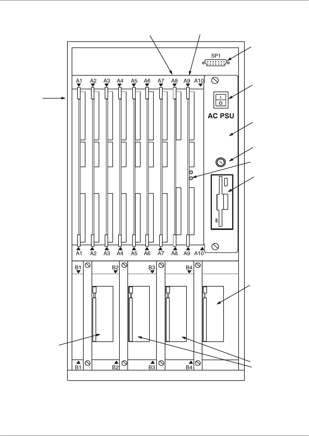
Hardware
Replacement 9-3
Octel Overture 200/300 Serenade 3.0
PB60014–01
Figure 9-1
Shelf Structure in the Octel Overture 200
Front System
Terminal Port
Power Supply
Unit
FloppyĆDiskette
Drive
Power Switch
System Fuse
Works Disk
Drive
System/Voice
Disk Drives
Voice Disk
Drive
VCU Slot CPU Slot
Seven
Card Slots
:
LIC, TLC, DAC,
or
Integration card
FAX card
LAN card
:
Entryworks ACP card
Reload Button
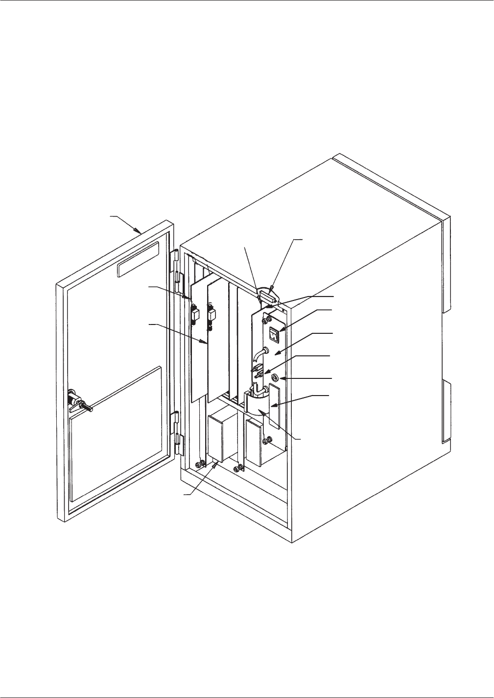
9-4
Installation and Maintenance
V
olume
Octel Overture 200/300 Serenade 3.0
PB60014–01
Figure 9-2
Inside Front V
iew of Octel Overture 200
Front Door
Disk Drive
Assembly
VCU
(Slot A8)
Front System Terminal
Port (SP1 Connector)
CPU (Slot A9)
Power Switch
Power Supply/
FloppyĆDrive Unit
Reload Button
FloppyĆDiskette Drive
Floppy Signal
Cable
Card Slot
Card Slot
System Fuse
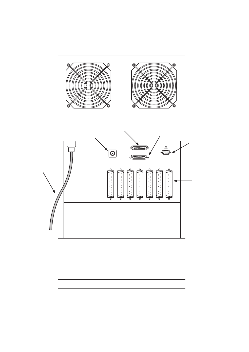
Hardware
Replacement 9-5
Octel Overture 200/300 Serenade 3.0
PB60014–01
Figure 9-3
Octel Overture 200 Cabinet Rear V
iew
RSĆ232C
Connector
(J2)
Alarm Port (J3)
I/O Panel
Visual Mailbox
Connector (J4)
Rear System
Terminal
Port (J1
connector)
J1
J2
J3
J4
Power Cord P1P2P3P4P5P6P7
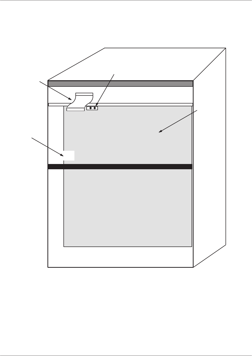
9-6
Installation and Maintenance
V
olume
Octel Overture 200/300 Serenade 3.0
PB60014–01
System
Terminal Port
Power Cord
Receptacle
Motherboard
Fan Power Harness
Connector
Figure 9-4
Inside Rear V
iew of Octel Overture 200

Hardware
Replacement 9-7
Octel Overture 200/300 Serenade 3.0
PB60014–01
Octel
Overture 300 Diagrams
Use
the following Octel Overture 300 diagrams to provide assistance when performing preventive
maintenance or replacing components. Figure 9-5 shows the Octel Overture 300 shelf structure.
Figure 9-6 through Figure 9-8 illustrate the front, rear
, and inside views of the Octel Overture 300 server
.
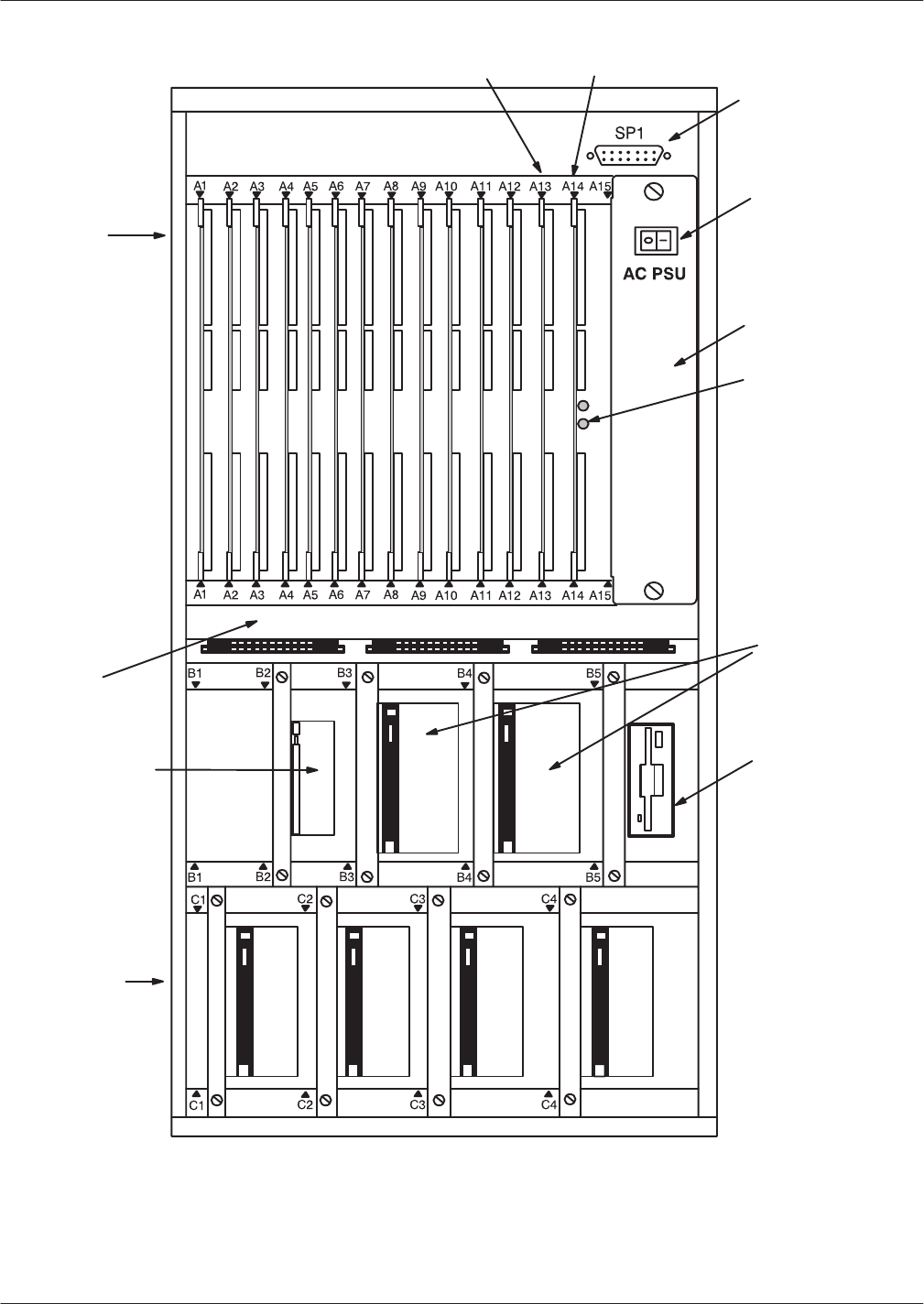
9-8
Installation and Maintenance
V
olume
Octel Overture 200/300 Serenade 3.0
PB60014–01
Figure 9-5
Shelf Structure of Octel Overture 300
Front System
Terminal Port
Power Supply
Unit
FloppyĆDiskette
Drive
Power Switch
Works Disk
Drive
Four Voice
Disk Drives
System/Voice
Disk Drives
Fan Tray
VCU Slot CPU Slot
Twelve
Card Slots
:
LIC, TLC, DAC,
or Integration
card
FAX card
LAN card
:
Entry ACP,
LIC, FAX, TLC,
Integration card
Reload Button
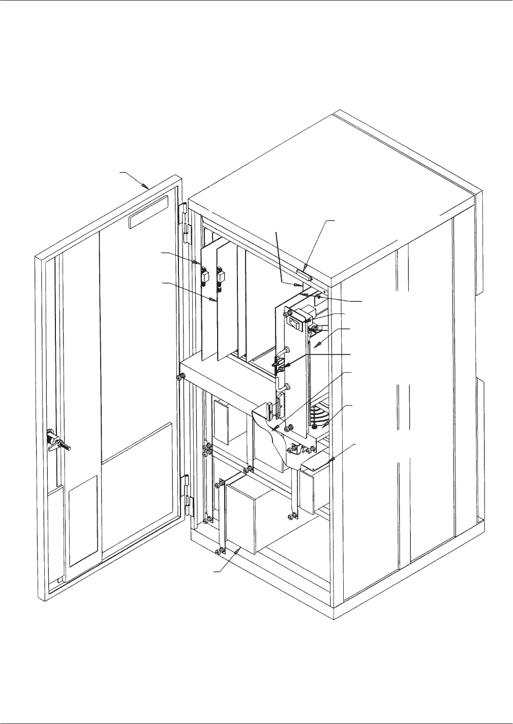
Hardware
Replacement 9-9
Octel Overture 200/300 Serenade 3.0
PB60014–01
Figure 9-6
Inside Front V
iew of Octel Overture 300
Front Door
Card Slot
Card Slot
HardĆDiskĆDrive
Assembly
VCU
(Slot A13)
Power Supply Unit
Fan Tray
Front System Terminal
Port (SP1 Connector)
CPU (Slot A14)
Floppy Signal Cable
Power Switch
FloppyĆDisk Drive
Reload Button
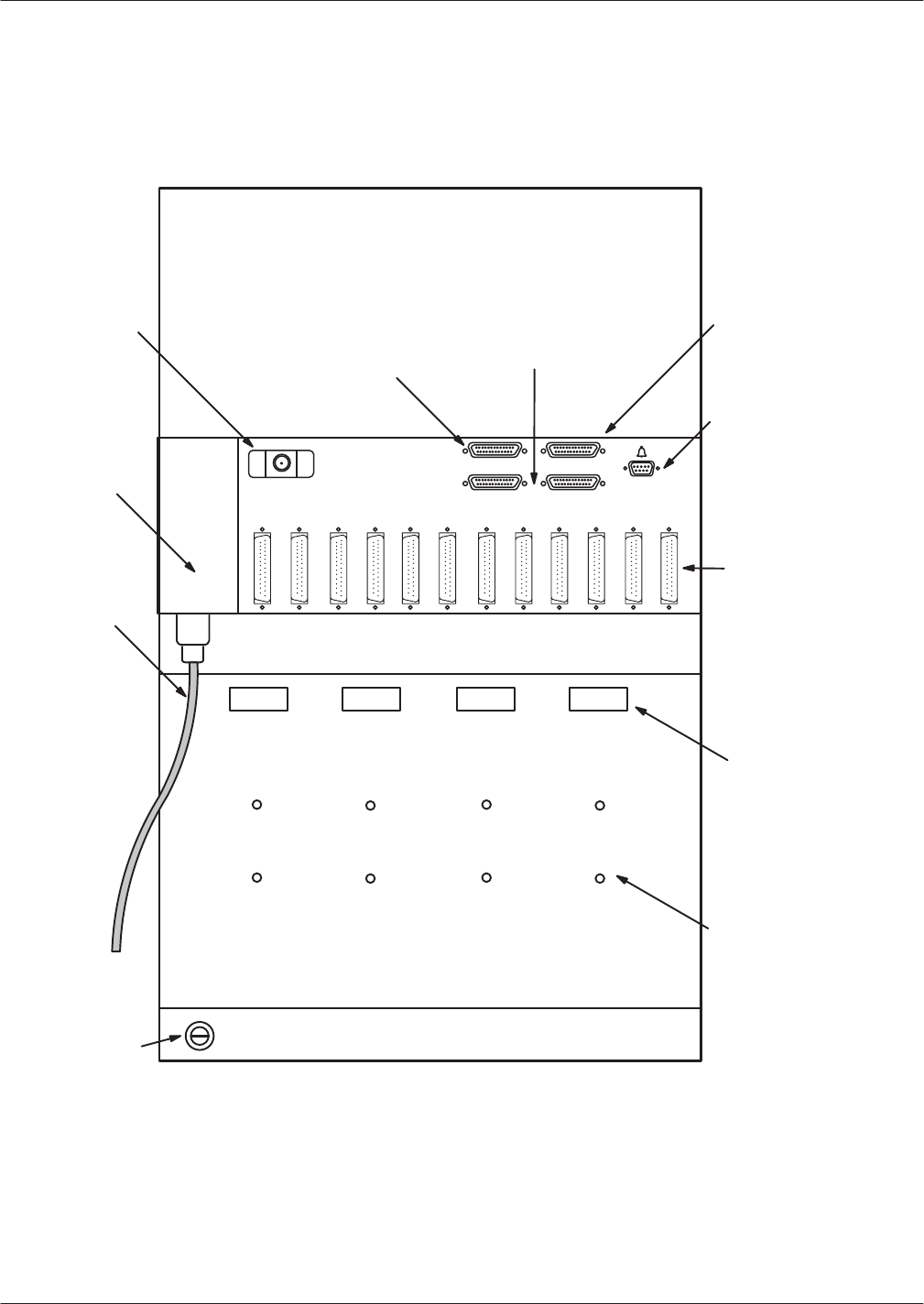
9-10
Installation and Maintenance
V
olume
Octel Overture 200/300 Serenade 3.0
PB60014–01
Figure 9-7
Rear V
iew of Octel Overture 300
J5
J4J3
J2J1
RSĆ232C
Connector
Port B (J2)
50Ćpin Telco
connectors
(25Ćpair Amphenol
connectors)
Power
Receptacle
Power Cord
Alarm Port (J5)
P1P2P3
P4
P5P6P7P8P9P10P11P12
Rear System Terminal
Port Connector (J1)
Reserved RSĆ232C
(J3 and J4
Connectors)
Earth Ground
Connection Point
J6
Visual Mailbox
Connector (J6)
Cable Tiedown
Points
Tapped Mounting
Holes (for securing
W
orks for Serenade
Serial I/O panel
and
DAC panel
)
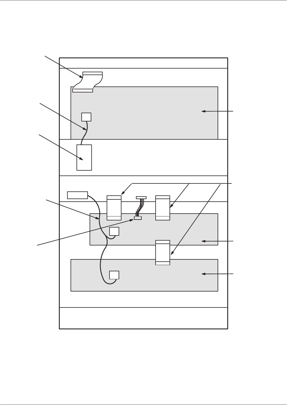
Hardware
Replacement 9-1
1
Octel Overture 200/300 Serenade 3.0
PB60014–01
Figure 9-8
Inside Rear V
iew of Octel Overture 300
System Terminal
Port Cable
Main Power
Harness
Power Line
Filter
Main Disk Drive
Power Harness
Main
Motherboard
(shelf A)
Fan Tray
Power Harness
SCSI Bus
Jumper Cable
Disk Drive
Motherboard
(shelf B)
Disk Drive
Motherboard
(shelf C)

9-12
Installation and Maintenance
V
olume
Octel Overture 200/300 Serenade 3.0
PB60014–01
9.2 HARDWARE
REPLACEMENT GUIDELINES
You
can safely replace subassemblies in Octel Overture 200 or Octel Overture 300 message servers by
following the procedures in succeeding sections. None of the subassemblies contain replaceable components;
replacing, attempting to replace, or modifying any component of a subassembly voids all warranties. Octel
can replace an assembly with an equivalent assembly
.
T
o install or replace a CPU, a VCU, floppy-disk drives, or the power supply unit, the power to the
message server must be turned OFF
. Refer to the Power Supply Unit section in this chapter for details
about turning OFF power to the cabinet. Hard-disk drives, line interface cards, integration cards, LAN
cards, and fax application processors can be replaced when the power is ON.
The message server must be restarted if a line interface card, integration card, or fax application
processor is added or if the replacement card is not the same as the card removed. Refer to the
Hard-Disk-Drive Replacement section in this chapter for considerations regarding hot plug
replacement of disk drives.
When replacing or installing subassemblies in an
Octel Overture 200/300 cabinet, use the following
guidelines:
Close and lock the cabinet door when not working on the cabinet. The door should not be left open
for more than 1 hour at a time.
Always wear an antistatic wrist strap before handling
any
parts.
Caution!
T
o avoid damaging electronic assemblies, wear an
antistatic wrist strap. Put on the strap
before
a
component is removed from its static bag. W
rap one
end around your wrist and attach the other end to an
unpainted part of the cabinet. The Octel Overture
200/300 must be plugged into a grounded outlet.
W
ear the strap during the entire replacement
procedure.
Printed
Circuit Assembly (PCA) Replacement
Use
this procedure to replace the following PCAs:
V
oice control units (VCU)
Central processing units (CPU)
T
o replace line interface cards (LIC), refer to the Line Interface Card Replacement section in this chapter
.
T
o replace integration cards, refer to the Integration Card Replacement section in this chapter
.
Caution!
Printed circuit assemblies, as well as other assemblies
in the Octel Overture 200/300, contain
static-sensitive components. The human body can
easily store enough static electricity to damage a
PCA. T
o avoid dischar
ging this ener
gy to electronic
assemblies,
always
wear an antistatic wrist strap
when handling assemblies.
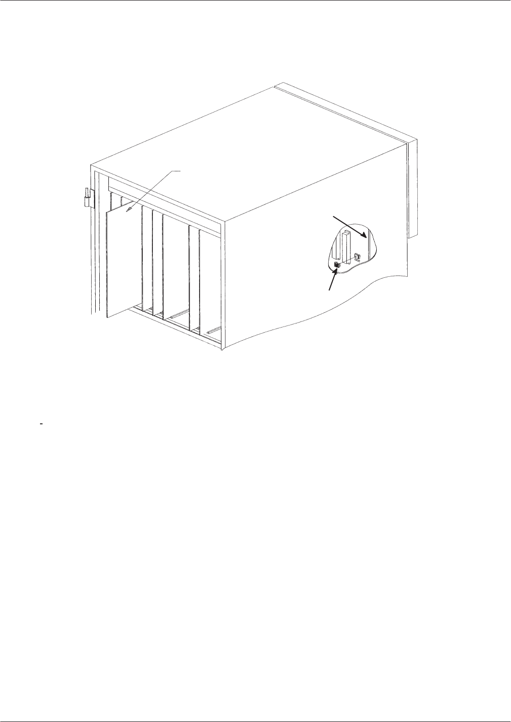
Hardware
Replacement 9-13
Octel Overture 200/300 Serenade 3.0
PB60014–01
Printed Circuit Assembly (PCA)
Motherboard
Option Control
Chip (OCC)
Figure 9-9
Card Cage Showing a Printed Circuit Assembly and an Option Control Chip
Replacing a PCA
Use
the following procedure to replace a VCU or CPU:
1.
Unlock and open the door of the cabinet.
2.
Put on an antistatic wrist strap. Connect it to an unpainted portion of the cabinet.
3.
Switch OFF the power supply unit.
4.
Disengage the PCA from the motherboard by pivoting the plastic card ejectors at the top and bottom
of the PCA front edge.
5.
Slide the PCA out of card cage.
Handle the PCA
only
by the top and bottom edges.
Do not
touch the components on the PCA.
6.
Store the removed PCA in a static protection bag.
7.
Remove the replacement PCA from its static protection bag.
8.
While holding the top and bottom edges of the replacement PCA, slide it into the card cage. Check
that the card slides in the plastic card guides to ensure correct insertion.
9.
Pivot the card ejectors, as needed, to grip the small flanges on the front edges of the card cage.
10.
Firmly seat the PCA connectors into the motherboard by pressing the ejectors against the front edge
of the PCA. The ejectors will clip onto small pins on the PCA when the connectors are seated.

9-14
Installation and Maintenance
V
olume
Octel Overture 200/300 Serenade 3.0
PB60014–01
Caution!
Do
not slam the PCA into the cabinet, as this could
damage the board or the motherboard connectors.
11.
Switch ON the power supply unit.
12. T
est the message server for correct operation.
13.
Close and lock the door to the cabinet.
Line
Interface Card Replacement
The
Octel Overture 200/300 line interface cards (4- and 8-port LIC, ILC12, and DLC16) installed in shelf
A are designed to be hot plugged; that is, the message server does not need to be turned OFF to remove
or install the cards.
The message server must be restarted if a line interface card is added or if the replacement card is
not the same as the card removed.
Caution!
No more than one line card at a time can be removed
or installed with the power ON; the ports must be
forwarded before removing the line card.
Removing Line Cards
Use
the following procedure to remove a line card:
1.
Unlock and open the door of the cabinet.
2.
Put on an antistatic wrist strap. Connect it to an unpainted portion of the cabinet.
3.
Forward the Octel Overture 200/300 ports being replaced.
T
o forward ports, at the @ prompt, type
CD x y z
In
this command,
x
is the slot,
y
is the first port in the card, and
z
is the last port in the card.
Y
ou can also use the command
TE C 1 x y
to forward the ports.
4.
Disengage the line card from the motherboard by pivoting the plastic card ejectors at the top and
bottom of the front edge of the line card.
5.
Slide the line card out of the card cage.
Handle the line card
only
by the top and bottom edges.
Do not
touch any components on the
line card.
6.
Store the removed line card in a static protection bag.

Hardware
Replacement 9-15
Octel Overture 200/300 Serenade 3.0
PB60014–01
Installing Line Cards
Use
the following procedure to install a line card:
1.
Put on an antistatic wrist strap. Connect it to an unpainted portion of the cabinet.
2.
While holding the top and bottom edges of the card, slide it into the card cage.
3.
Pivot the card ejectors, as needed, to grip the small flanges on the front edges of the card cage.
4.
Firmly seat the line card connectors into the motherboard by pressing the ejectors against the front
edge of the line card. The ejectors will clip onto small pins on the line card when the connectors are
seated.
Caution!
Do not slam the line card into the cabinet, as this
could damage the board or motherboard connectors.
Once the line card is installed, the red LED comes ON. When self-test diagnostics are complete, the
green LED comes ON. When the card has been initialized and is ready for operation, the red LED
goes OFF
.
5.
Initialize the ports, by typing
CU x y z
In
this command,
x
is the slot,
y
is the first port in the card, and
z
is the last port in the card.
Y
ou can also use the command
TE C 2 x y
to initialize the ports.
6. T
est the message server for correct operation.
7.
Close and lock the door to the cabinet.
Integration
Card Replacement
The
Octel Overture 200/300 integration cards installed in shelf A are designed to be hot plugged; that is,
the message server does not need to be turned OFF to remove or install the cards.
The message server must be restarted if an integration card is added or if the replacement card is
not the same as the card removed.
Caution!
No more than one integration card at a time can be
removed or installed with the power ON.

9-16
Installation and Maintenance
V
olume
Octel Overture 200/300 Serenade 3.0
PB60014–01
Removing Integration Cards
Use
the following procedure to replace an integration card:
1.
Unlock and open the door of the cabinet.
2.
Put on an antistatic wrist strap. Connect it to an unpainted portion of the cabinet.
3.
Use the Courtesy Down command to take the integration card out of service. At the @ prompt, type
CD x y
In this command,
x
is the slot number, and
y
is the unit number
.
4.
Disengage the integration card from the motherboard by pivoting the plastic card ejectors at the top
and bottom front edge of the card.
5.
Slide the integration card out of the card cage, handling the card only by the top and bottom edges.
Do not
touch the components on the card.
6.
Store the removed integration card in a static protection bag.
Installing Integration Cards
Use
the following procedure to install an integration card:
1.
Put on an antistatic wrist strap. Connect it to an unpainted portion of the cabinet.
2.
While holding the top and bottom edges of the card, slide it into the card cage.
3.
Pivot the card ejectors, as needed, to grip the small flanges on the front edges of the card cage.
4.
Firmly seat the integration card connectors into the motherboard by pressing the ejectors against the
front edge of the card. The ejector will clip onto small pins on the integration card when the
connectors are seated.
Caution!
Do not slam the integration card into the cabinet, as
this could damage the board or motherboard
connectors.
Once the integration card is installed, the red LED comes ON. When self-test diagnostics are
complete, the green LED comes ON. When the card has been initialized and is ready for operation,
the red LED goes OFF (less than 5 minutes).
5.
Use the Courtesy Up command to initialize the integration card. At the @ prompt, type
CU x y
In this command,
x
is the slot number, and
y
is the unit number
.
If there are two units, make sure to initialize both units.
Repeat this step for unit 2.
6. T
est the message server for correct operation.
7.
Close and lock the door to the cabinet.

Hardware
Replacement 9-17
Octel Overture 200/300 Serenade 3.0
PB60014–01
Local
Area Network (LAN) Card Replacement
The
LAN card installed in shelf A is designed to be hot plugged; that is, the message server does not need
to be turned OFF to remove or install the card.
Only one LAN card can be installed in an Octel Overture 200/300 message server
. The LAN card can be
installed in the following locations:
Slots A5 through A7 for the Octel Overture 200
Slots A10 through A12 for the Octel Overture 300
Removing a LAN Card
Use
the following procedure to remove a LAN card:
1.
Before servicing a LAN card, use the Courtesy Down command to take the LAN card out of service.
At the @ prompt, type
CD x
In this command,
x
is the slot number
.
2.
Unlock and open the door of the cabinet.
3.
Put on an antistatic wrist strap. Connect it to an unpainted portion of the cabinet.
4.
Disengage the LAN card from the motherboard by pivoting the plastic card ejectors on the top and
bottom front edge of the LAN card.
5.
Slide the LAN card out of the card cage.
Handle the LAN card only by the top and bottom edges.
Do not
touch components on the
LAN card.
6.
Store the removed LAN card in a static protection bag.
Installing a LAN Card
Use
the following procedure to install a LAN card:
1.
Put on an antistatic wrist strap. Connect it to an unpainted portion of the cabinet.
2.
While holding the top and bottom edges of the LAN card, slide it into the card cage.
3.
Pivot the card ejectors, as needed, to grip the small flanges on the front edges of the card cage.
4.
Firmly seat the LAN card connectors into the motherboard by pressing the ejectors against the front
edge of the LAN card. The ejectors will clip onto small pins on the LAN card when the connectors
are seated.
Caution!
Do not slam the LAN card into the cabinet, as this
could damage the board or motherboard connectors.
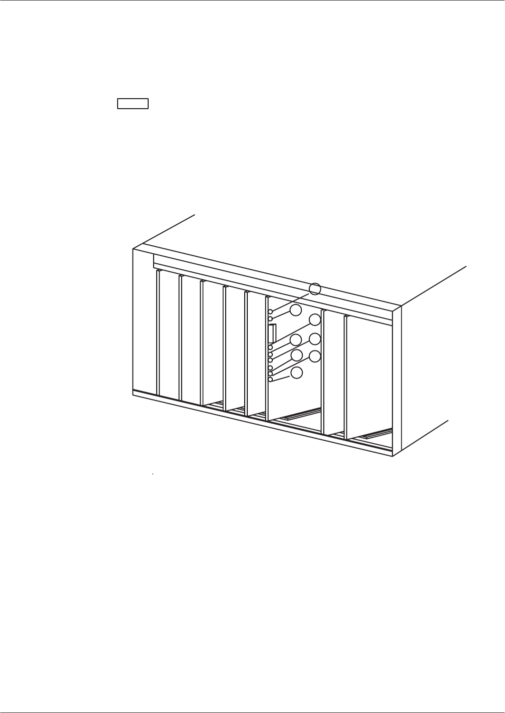
9-18
Installation and Maintenance
V
olume
Octel Overture 200/300 Serenade 3.0
PB60014–01
5. Install
the 10BaseT
, RJ45 adapter on the back of the cabinet, for the slot in which the LAN card is
being installed.
6.
After servicing the LAN card, use the Courtesy Up command to put the card into service. At the @
prompt, type
CU x
In this command,
x
is the slot number
.
7. T
est the message server for correct operation.
8.
Close and lock the door to the cabinet.
Figure 9-10 shows the eight LEDs on the front edge of the LAN card.
Figure 9-10
LED Placement on the LAN Card

Hardware
Replacement 9-19
Octel Overture 200/300 Serenade 3.0
PB60014–01
Once
the LAN card is installed, the LEDs on the LAN card are activated, as follows:
LED
Number LED
Description
LED
Color
LED Activity
1Standard
use
Red
Lit when the LAN card is installed.
Goes of
f when the card has been initialized and is
ready for operation.
2
Standard use
Green
Lit when self-test diagnostics are complete.
3Development Yellow
Used only for development.
4
Good link indicator
Yellow
Lit when the adapter and wiring to a hub are correct.
5
Rx polarity reversed
Yellow
Lit if the pair being received by the Ethernet
controller needs to be reversed. Check the wiring.
6
Receive activity
Indicator Yellow
Lit when the Ethernet controller sees activity on the
receive pair
.
7T
ransmit activity
indicator Yellow
Lit when the Ethernet controller sees activity on the
transmit pair
.
8
Collision Indicator
Yellow
Lit when a collision occurs. Collisions occur normally
in Ethernet/802.3 networks, because it is part of the
low layer protocol.
DTIC
Replacement
The
Digital T
runk Interface Cards (DTIC) installed in Shelf A are designed to be hot plugged; that is, the
system does not need to be powered down to remove or install the cards.
Caution!
No more than one card at a time may be removed or
installed with power ON.
Removing a DTIC Card
The
procedure to replace a DTIC is as follows:
1.
Unlock and open the door of the cabinet.
2.
Put on antistatic wrist strap. Connect it to an unpainted portion of the cabinet.
The ports cannot be forwarded.
3.
Disengage the DTIC from the motherboard by pivoting the plastic card ejectors on the top and
bottom of the line card front edge.
4.
Slide the DTIC out of the card cage.
Handle the DTIC only by the top and bottom edges.
Do not
touch components on the card.
5.
Store removed card in a static protection bag.

9-20
Installation and Maintenance
V
olume
Octel Overture 200/300 Serenade 3.0
PB60014–01
Installing a DTIC Card
The
procedure to install a DTIC is as follows:
For a new installation, configure the SLOTS T
able for the DTIC card before the card is installed.
1.
Put on antistatic wrist strap. Connect it to an unpainted portion of the cabinet.
For a first-time installation, the DTIC–E1 kit must be installed. Follow steps 2 and 3, then follow the
steps for either a 75-ohm or 120–ohm DTIC-E1 adapter installation. If this is not a new installation,
go to step 5.
2.
Remove two jack screws and washers securing the connector marked J2 (for the Octel Overture 200)
or J4 (for the Octel Overture 300) to the I/O panel on the back of the system. Refer to Figure 9-1
1 for
the Octel Overture 200 or Figure 9-12 for the Octel Overture 300.
3.
Using two new jack screws provided with the kit and washers just removed, attach the grounding
strip where shown in Figure 9-1
1 for the Octel Overture 200 or Figure 9-12 for the Octel Overture
300.
4.
Install the DTIC adapter
.
For 75-ohm DTIC-E1 installations:
a.
Connect the 75-ohm DTIC–E1 adapter
, to the amphenol connector on the I/O panel
corresponding to the DTIC card slot in the system card cage. Secure the velcro strap. Make sure
that the adapter is completely seated.
b.
Secure the grounding screw on the top of the adapter to the grounding strip.
c.
Attach the customer
-provided 75-ohm transmit and receive coax cables to the appropriate coax
connectors on the adapter where shown in Figure 9-13. Go to step 5.
For 120-ohm DTIC-E1 installations:
a.
Prepare the customer-provided I/O cable as follows:
Cut the cable jacket so that the conductors protrude approximately 25mm (1 inch) from the
end of the jacket.
Strip approximately 6mm (.25 inch) of insulation from the end of each conductor
.
Cut the shield so that a 13 mm (.5 inch) length of shield foil or braid can be pulled back
over the cable jacket.
T
o pass regulatory requirmenets, shielded cable must be used.
b.
Connect the conductors from the I/O cable to teh 120-ohm adapter s shown in Figure 9-14.
c.
Secure the jacket of the cable to the adapter using the clamp provided or remove the clamp and
secure with a tie-wrap through 2 small rectangular cutouts. Make sure the clamp or tie wrap
clamp-down around the shield that has been folded back around the cable jacket.
d.
Connect the adapter to the amphenol connector on the I/O pannel corresponding to the DTIC-E1
card slot in the system card cage. Secure the velcro strap. Make sure the adapter is completely
seated.
e.
Secure the gorunding screw on the top of the adapter to the grounding strip. Go to step 5.
5.
Check that the DTIC’s SW1 adn SW2 switches at the bottom right-hand corner of the card are set to
the correct positions; 75-ohm or 120-ohm. these switches and their settings are marked on the card.
6.
While holding top and bottom edges of the card, slide the DTIC into the card cage.

Hardware
Replacement 9-21
Octel Overture 200/300 Serenade 3.0
PB60014–01
7. Pivot
the card ejectors as needed to grip small flanges on the front edges of the card cage.
8.
Firmly seat the DTIC connectors into the motherboard by pressing ejectors against the front edge of
the card. The ejectors will clip onto small pins on the DTIC when the connectors have seated.
Caution!
No more than one card at a time may be removed or
installed with power ON.
9.
At the @ prompt, enter
RESTA
to restart the system. The information on the DTIC card is
downloaded to the system and the DTIC becomes operational. If the card is being hot plugged, the
system does not need to be restarted.
Once the DTIC is installed, the uppermost red LED comes ON. When selftest diagnostics are
complete, the red LED remains ON and the uppermost green LED comes ON, indicating that the
card is ready for application code download and initialization.
After a delay of 10 to 15 seconds, only the uppermost green LED remains lit, indicating normal
operation of the DTIC application code. This green LED stays ON even if problems are detected
with the E1 trunk or other aspects of initialization. However
, if there are problems, the LEDs below
the green power LED will light to indicate the nature of the problem. Otherwise, these other LEDs
remain OFF
. Refer to the following table for the LEDs and their meanings.
LED Meaning
Red boot (top)
Apcode is initializing
Green Power
DTIC has power
Red 1 (top)
Loss of signal on trunk (LOS)
Red 2
Loss of frame on trunk (LOF)
Y
ellow 3
Remote alarm indication (RAI)
Y
ellow 4
“Other” trunk alarm
Y
ellow 5
Alarm history
Green 6 (bottom)
One or more channels of
f hook
10.
Initialize ports by entering
CU x y z
where
x
is the slot,
y
is the first port in the card, and
z
is the last port in the card. If
y
and
z
are not
specified, it defaults to all ports on the card.
The command
TE C 2 x y
may also be used .
11. T
est system for proper operation.
12.
Close and lock the door to the cabinet.
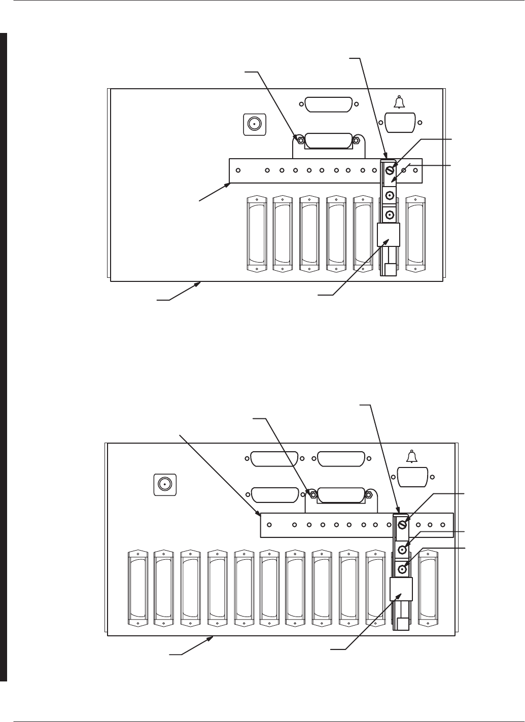
9-22
Installation and Maintenance
V
olume
Octel Overture 200/300 Serenade 3.0
PB60014–01
Figure 9-11
DTIC–E1 Kit Installation for the Octel Overture 200
2X New Jack Screws
DTIC-E1 Adapter
Grounding
Screw
I/O Cabling
installed here.
Refer to the
figure for the
75Ćohm or
the 120Ćohm
adapter.
Grounding Strip
Velcro HoldĆdown
I/O Panel
Figure 9-12
DTIC–E1 Kit Installation for the Octel Overture 300
2X New Jack Screws
DTIC-E1 Adapter
Grounding
Screw
Grounding Strip
Velcro HoldĆdown
I/O Panel
I/O Cabling
installed here.
Refer to the
figure for the
75Ćohm or
the 120Ćohm
adapter.
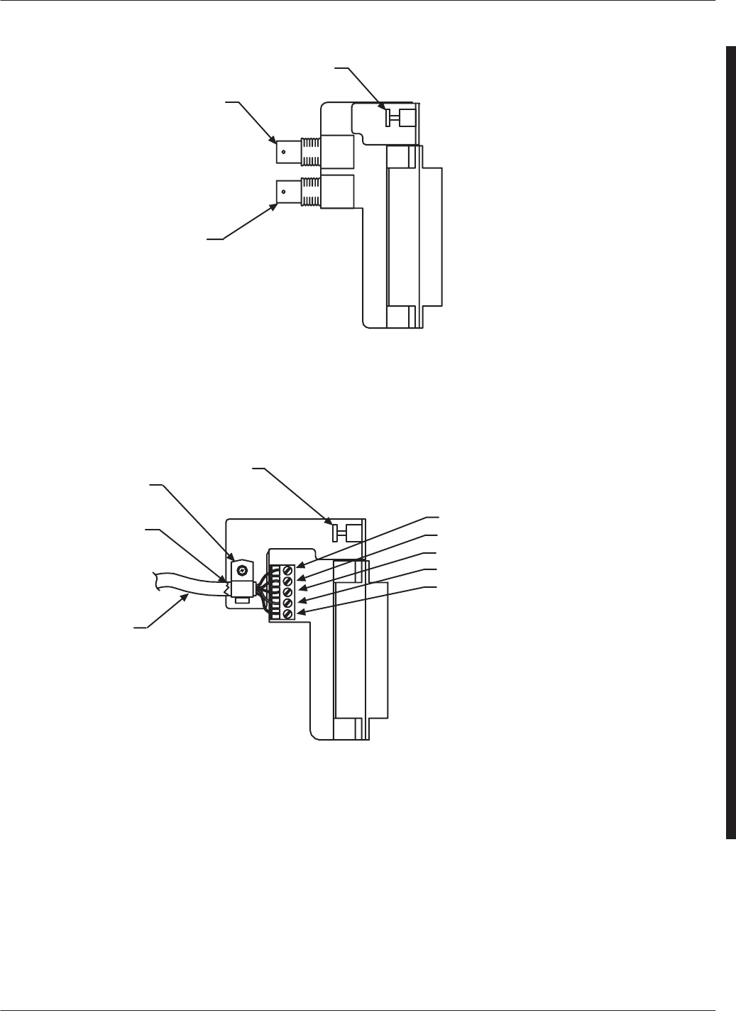
Hardware
Replacement 9-23
Octel Overture 200/300 Serenade 3.0
PB60014–01
Transmit
Receive
Note: “Transmit”
and
“Receive”
are referenced from the voice
server (i.e. DTIC–E1) side.
Grounding
Screw
Figure 9-13 75-ohm DTIC-E1 Adapter
Folded–back
cable shield
foil or braid
Cable Clamp
I/O Cable
Tx Ring
Tx Tip
Chassis Ground
Rx Ring
Rx T
ip
Note: I/O Cable bare metal
ground
“drain wire
” should
be connected to pin 3
(chassis ground) on the 5–
position termial block.
Tx = DTIC T
ransmit
Rx= DTIC Receive
Grounding
Screw
Figure 9-14 120-ohm DTIC-E1 Adapter
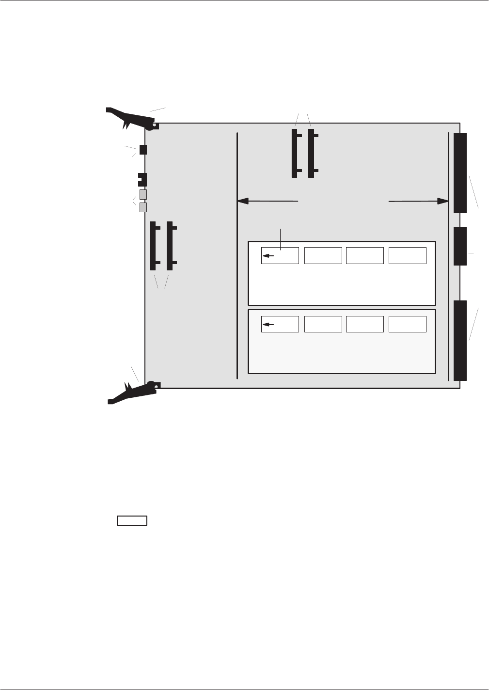
9-24
Installation and Maintenance
V
olume
Octel Overture 200/300 Serenade 3.0
PB60014–01
Fax
Application Processor Replacement
The
Octel Overture 200/300 fax application processors (fax cards) installed in shelf A are designed to be
hot pluggable; that is, the message server does not need to be turned OFF to remove or install the cards.
Figure 9-15 is a diagram of a fax card.
Front
Front
Card Stiffeners
Fax Daughter Card 2 (channels 5-8)
(solder side up)
SIMM Modules
SIMM
Modules
Red
Green
Amber
Card Ejector
Card Ejector
DB1 DB2
Fax Daughter Card 1 (channels 1-4)
(solder side up)
Backplane Connectors
Orientation Label
Figure 9-15
Fax Application Processor
Removing Fax Application Processors
Use
the following procedure to remove a fax card:
1.
Before servicing a fax application processor
, use the Courtesy Down command to take the fax card
out of service. At the @ prompt, type
CD x Enter
In
this command,
x
is the slot number
.
2.
Unlock and open the door of the cabinet.
3.
Put on an antistatic wrist strap. Connect it to an unpainted portion of the cabinet.
4.
Remove the fax card from the Octel Overture 200/300 cabinet by pivoting the plastic card ejectors at
the top and bottom front edge of the card and sliding the card out of the card cage.
Handle the fax card
only
by the top and bottom edges.
Do not
touch components on the card.
5.
Store the removed fax card in a static protection bag.

Hardware
Replacement 9-25
Octel Overture 200/300 Serenade 3.0
PB60014–01
Installing Fax Application Processors
Use
the following procedure to install a fax card:
1.
Put on an antistatic wrist strap. Connect it to an unpainted portion of the cabinet.
2.
While holding the top and bottom edges of the fax card, slide it into the card cage, taking care to
align the card on the card guides and not let the daughter cards touch nearby cards.
3.
Pivot the card ejectors, as needed, to grip the small flanges on the front edges of the card cage.
4.
Firmly seat the fax card connectors into the motherboard by pressing the ejectors against the front
edge of the fax card. The ejectors will clip onto the small pins on the fax card when the connectors
are seated.
Caution!
Do not slam the fax card into the cabinet, as this
could damage the card or motherboard connectors.
Once the fax card is installed, the red LED comes ON. When the self-test diagnostics are complete,
the green LED comes ON. When the card has been initialized and is ready for operation, the red
LED goes OFF
.
5.
Use the Courtesy Up command to put the card into service. At the @ prompt, type
CU x
In this command,
x
is the slot number of the fax card.
6. T
est the fax card for correct operation. Refer to the
Featur
e Description
volume, Fax Mail Plus
chapter, T
esting the Fax Application Processor section, for testing procedures.
7.
Close and lock the door to the cabinet.
Hard-Disk-Drive
Replacement
Hard-disk
drives are already installed in the message server cabinet when it is shipped. When a
replacement is required, certain procedures must be followed to restore a message server to normal
operation.
Hot plug replacement of hard-disk drives is supported. Drives inserted hot are not operational until the
Disk Options (
DISKO
) program is run. There is no online Disk Options program. However
, the command
to add, remove, or replace hard-disk drives must still be issued using the Disk Options program when the
message server is booted from a floppy diskette.
Y
ou must restart the message server if the hard-disk drive has been replaced.
Refer to the Procedures chapter in this volume, Hard-Disk Replace and Hard-Disk Add sections.
Only
hard-disk drives supplied by Octel can be used to replace or to upgrade a message server
. The disk
drive assembly includes
all necessary
cables.
Do not r
emove or alter any cables on the drive
assembly.
Figure 9-16 shows the hard-disk-drive assembly for the Octel Overture 200. Figure 9-17 shows
the hard-disk-drive assembly for the Octel Overture 300.
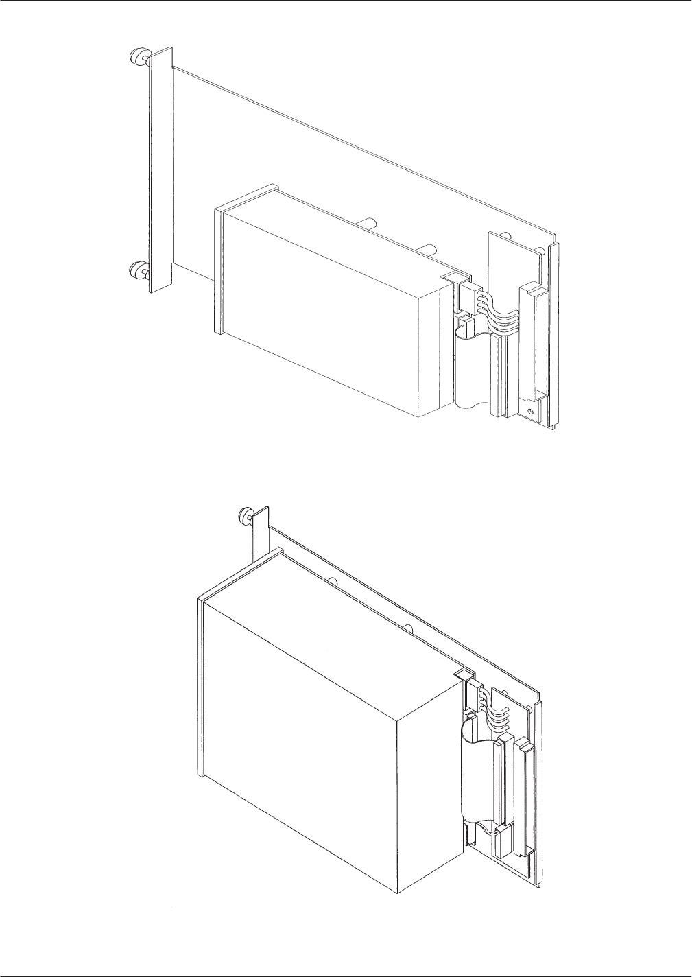
9-26
Installation and Maintenance
V
olume
Octel Overture 200/300 Serenade 3.0
PB60014–01
Figure 9-16
Octel Overture 200 Hard-Disk-Drive Assembly
Figure 9-17 Octel Overture 300 Hard-Disk-Drive Assembly

Hardware
Replacement 9-27
Octel Overture 200/300 Serenade 3.0
PB60014–01
Caution!
The
hard-disk-drive assemblies are sensitive to static
electricity
. Do not attempt the following procedures
without wearing an antistatic wrist strap.
Removing the Hard-Disk Drive
To
remove the hard-disk drive, use the following procedures:
1.
Unlock and open the door of the cabinet.
2.
Put on an antistatic wrist strap. Connect it to an unpainted portion of the cabinet.
3.
Locate the drive assembly to be removed.
4.
Using a flat-bladed screwdriver
, loosen the two captive screws that secure the hard-disk drive to the
cabinet.
5.
Gripping the front flange, pull the drive assembly out of the cabinet. Use one hand to support the
bottom of the drive when it clears the cabinet.
6.
Carefully place the drive assembly nearby, to be reinstalled or shipped.
The hard-disk-drive assemblies are sensitive to rough handling. Be careful and handle them as
gently as possible.
Installing the Hard-Disk Drive
To
replace the hard-disk drive, use the following procedures:
The disk drive ID will automatically be selected when the drive assembly is installed. Do not
change the jumpers on the disk drive.
1.
Put on an antistatic wrist strap. Connect it to an unpainted portion of the cabinet.
2.
Remove the new disk drive from the shipping container
.
3. V
erify that the part number on the label attached to the sheet-metal plate of the hard-disk-drive
assembly agrees with what was ordered.
For part numbers and storage hours, refer to the Hardware chapter in this volume.
4.
Hold the disk drive with your right hand, grasping the front flange with your left hand supporting the
weight of the drive. The drive should be to the right of the metal slider plate.
5.
Guide the sheet-metal plate into the card guides that are marked with the appropriate slot ID.
6. Gently
, but firmly
, slide the drive assembly into the slot until the connector on the back of the
assembly is mated with the connector on the backplane. This is accomplished when the flange on the
front of the drive-assembly sheet metal reaches or very nearly reaches the sheet metal of the cabinet.
Caution!
Do not slam the drive assembly into cabinet. This
could damage the disk drive.
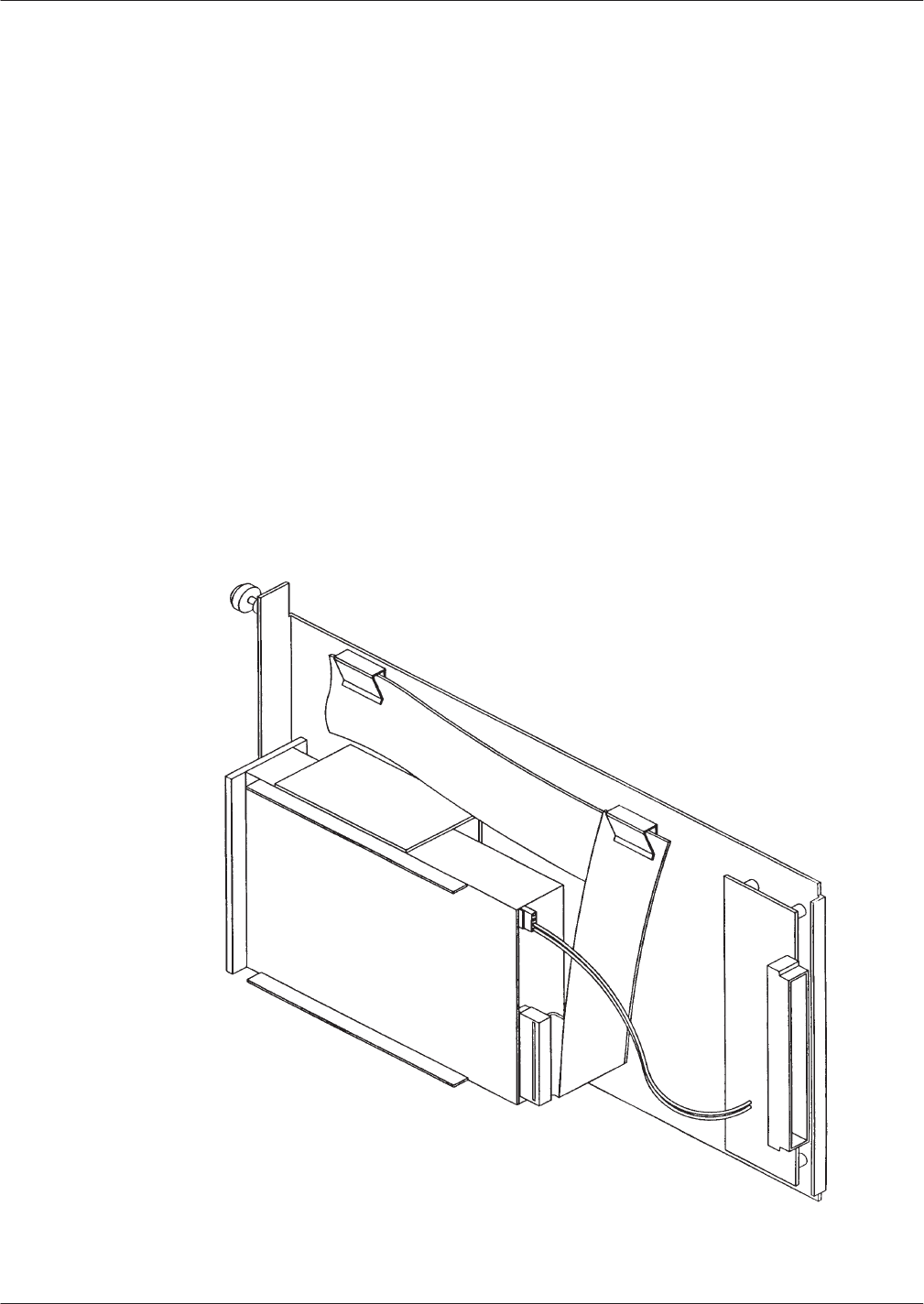
9-28
Installation and Maintenance
V
olume
Octel Overture 200/300 Serenade 3.0
PB60014–01
7. Using
a flat-bladed screwdriver
, tighten the two captive screws that are attached to the front flange of
the drive assembly
.
8.
Follow the procedure in the Procedures chapter
, Hard-Disk Restore/Add/Replace section, in this
volume, to restore the message server to correct configuration.
9. T
est the message server for correct operation.
Octel
Overture 300 Floppy-Disk-Drive Replacement
In
the event of damage or a malfunction, an
Octel Overture 300 floppy-disk drive might need to be
replaced.
Only
floppy-disk drives supplied by Octel can be used to replace a drive or to upgrade a message
server
. The disk-drive assembly includes
all necessary
cables.
Do not r
emove or alter any cables on the
drive assembly
.
Figure 9-18 shows the floppy-disk-drive assembly for the Octel Overture 300.
For the Octel Overture 200, the power supply and the floppy drive are part of the power supply
unit. If the floppy-disk drive malfunctions, these subassemblies must be replaced as a unit. Refer
to the Power Supply Unit Replacement section in this chapter to replace an
Octel Overture 200
floppy-disk drive.
Figure 9-18
Octel Overture 300 Floppy-Disk-Drive Assembly

Hardware
Replacement 9-29
Octel Overture 200/300 Serenade 3.0
PB60014–01
Caution!
The
floppy-disk drive assemblies are sensitive to
static electricity
. Do not attempt the following
procedures without wearing an antistatic wrist strap.
Removing the Octel Overture 300 Floppy-Disk Drive
The
Octel Overture 300 floppy-disk-drive assembly is a hot pluggable assembly
. Y
ou do not need to turn
OFF the power supply unit. T
o remove the floppy-disk-drive assembly
, use the following procedures:
1.
Unlock and open the door of the cabinet.
2.
Put on an antistatic wrist strap. Connect it to an unpainted portion of the cabinet.
3.
Locate the floppy-disk-drive assembly
.
4.
Remove the configuration backup diskette from the floppy-disk drive.
5.
Disconnect the floppy-disk signal cable from the front of the CPU card.
6.
Using a flat-bladed screwdriver
, loosen the two captive screws that secure the floppy-disk drive to
the cabinet.
7.
Gripping the front flange, pull the drive assembly firmly to unseat the rear-mounted connector
.
Continue to pull the drive out of the cabinet. Use one hand to support the bottom of the drive when it
clears the cabinet.
8.
Carefully put the floppy-drive assembly nearby
, to be reinstalled or shipped.
Floppy-disk-drive assemblies are sensitive to rough handling. Be careful and handle them as
gently as possible.
Installing Octel Overture 300 Floppy-Disk Drive
The
Octel Overture 300 floppy-disk-drive assembly is hot pluggable. Y
ou do not need to turn OFF the
power supply unit. T
o install a replacement floppy-disk drive in the Octel Overture 300, use the following
procedure:
1.
Put on an antistatic wrist strap. Connect it to an unpainted portion of the cabinet.
2.
Remove the replacement floppy-disk-drive assembly from the shipping container
.
3.
Hold the floppy-disk drive with your right hand, grasping the front flange, with your left hand
supporting the weight of the drive. The drive should be to the right of the sheet-metal slider plate.
4.
Guide the sheet-metal plate into the card guides marked “B5.”
5. Gently
, but firmly
, slide the drive assembly into the slot until the connector on the back of the
assembly has mated with the connector on the backplane. This is accomplished when the flange on
the front of the drive assembly sheet metal reaches or very nearly reaches the sheet metal of the
cabinet.
Caution!
Do not slam the floppy-disk-drive assembly into the
cabinet. This could damage the floppy-disk drive.
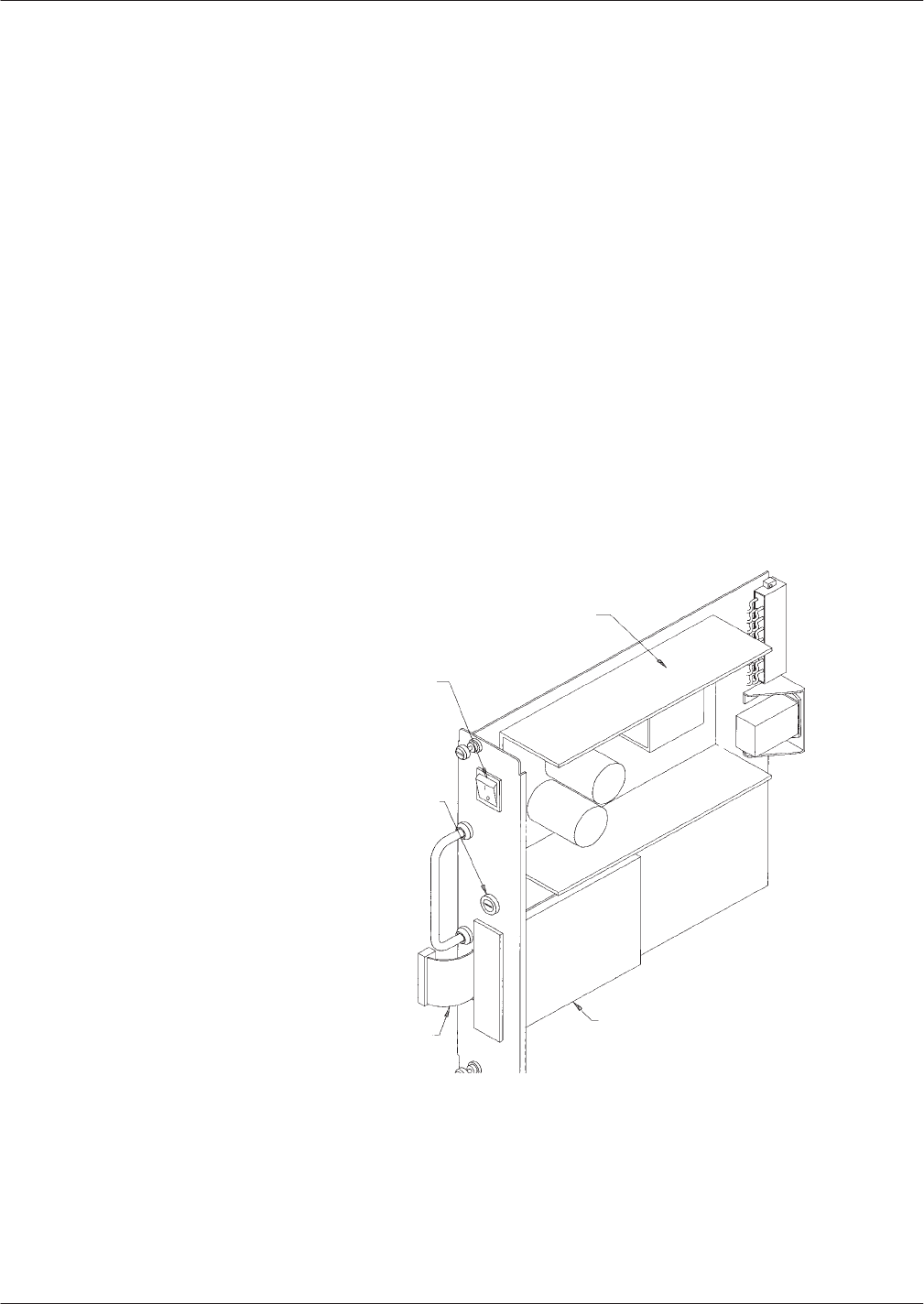
9-30
Installation and Maintenance
V
olume
Octel Overture 200/300 Serenade 3.0
PB60014–01
6. Using
a flat-bladed screwdriver
, tighten the two captive screws that are attached to the front flange of
the drive assembly
.
7.
Connect the keyed connector on the floppy-drive signal cable to the connector on the CPU card.
8.
Insert the configuration backup diskette into the floppy-disk drive.
9. T
est the message server for correct operation.
Power Supply Unit Replacement
If
the power supply unit malfunctions, it must be replaced with a new one. No attempt should be made to
replace or alter the power supply’
s circuit components or wire harness. No power supply adjustments are
possible.
For the Octel Overture 200, the power supply and floppy-disk drive are part of the power supply unit.
If either the power supply or floppy-disk drive malfunctions, you must replace the entire unit. The
instructions used to remove and install the power supply are the same instructions used to replace an
Octel Overture 200 floppy-disk drive. Figure 9-19 shows the power supply unit for an Octel Overture
200.
Power Supply
Power Switch
Fuse Holder
Cable to
FloppyĆDisk Drive FloppyĆDisk Drive
Figure 9-19
Octel Overture 200 Power Supply Unit
For
the Octel Overture 300, the power supply unit and the floppy-disk drive can be replaced
separately
. Refer to the Octel Overture 300 Floppy-Disk-Drive Replacement section to remove an
Octel Overture 300 floppy-disk drive. Figure 9-20 shows the power supply assembly for the Octel
Overture 300.
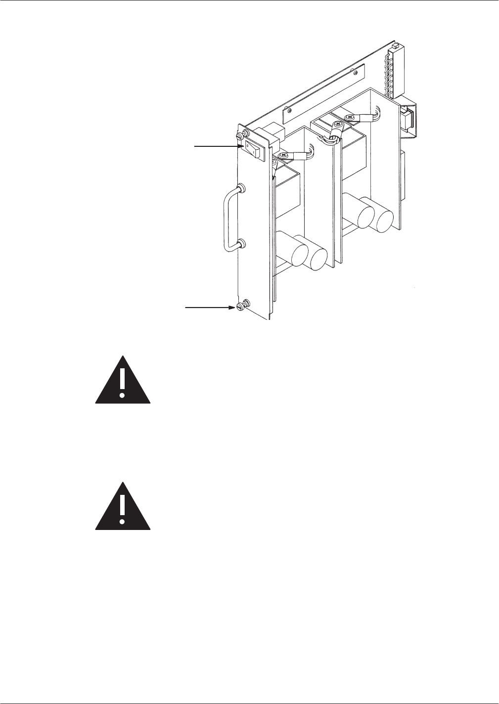
Hardware
Replacement 9-31
Octel Overture 200/300 Serenade 3.0
PB60014–01
Figure 9-20
Octel Overture 300 Power Supply Assembly
Circuit Breaker
Captive ChassisĆ
Mounting Screws
Caution!
The power supply unit is sensitive to static electricity
.
Do not attempt the following procedures without
wearing an antistatic wrist strap.
Removing the Power Supply Unit
Use
the following procedure to remove the power supply unit:
Caution!
The power supply unit is
not
hot pluggable.
Do not
remove the power supply unit when it is ON.
1.
Unlock and open the door of the cabinet.
2.
Put on an antistatic wrist strap. Connect it to an unpainted portion of the cabinet.
3. T
urn OFF the power to the message server at the switch on the front of the power supply unit. The
switch for the power supply unit is a circuit-breaker rocker switch.
On the Octel Overture 200, the switch is OFF when the bottom of the rocker
, marked 0, is pressed in.
The switch is ON when the top of the rocker
, marked 1, is pressed in.
On the Octel Overture 300, the switch is OFF when the side of the rocker
, marked 0, is pressed in.
The switch is ON when the side of the rocker
, marked 1, is pressed in.

9-32
Installation and Maintenance
V
olume
Octel Overture 200/300 Serenade 3.0
PB60014–01
Caution!
To
avoid risk of electric shock, wait 2 minutes after
turning OFF the message server to remove the power
supply unit.
4.
Remove the floppy-disk-drive signal cable from the CPU.
5.
Using a flat-bladed screwdriver
, loosen the two captive screws on the front of the power supply unit.
6.
Gripping the power supply unit handle, pull the power supply unit firmly to unseat the rear
-mounted
connectors. Continue to pull out the power supply unit, ready to support the bottom of the power
supply unit with one hand when it clears the cabinet.
Installing the Power Supply Unit
To
install the power supply unit, use the following procedure:
1.
Put on an antistatic wrist strap. Connect it to an unpainted portion of the cabinet.
2. V
erify that the power supply switch is OFF
. The power supply unit switch is a circuit-breaker rocker
switch.
On the Octel Overture 200, the power supply unit switch is OFF when the bottom of the rocker
,
marked 0, is pressed in. The switch is ON when the top of the rocker
, marked 1, is pressed in.
On the Octel Overture 300, the switch is OFF when the side of the rocker
, marked 0, is pressed
in. The switch is ON when the side of the rocker
, marked 1, is pressed in.
Caution!
Installing the power supply unit with the circuit
breaker ON and the power cord attached to the
primary power could damage the power supply unit
or the message server
.
3.
Pick up the power supply unit with one hand on the handle and the other hand under the unit to
support its weight. Support the power supply by holding the sheet-metal slider.
Do not
touch any
power
-supply electrical components or wiring.
4.
Line up the edges of the power
-supply-unit sheet metal, with the card guides marked A10 on the
Octel Overture 200 and A15 on the Octel Overture 300, and slide the power supply unit halfway into
the cabinet. Remove your supporting hand from the bottom of the sheet-metal plate.
5.
Once again, confirm that the circuit breaker is OFF
.
6. Gently
, but firmly
, continue to slide the power supply unit into the cabinet by pushing on the handle
until the connectors on the back of the unit have mated with the connectors on the motherboard. This
is accomplished when the flange on the front sheet metal of the power supply unit reaches or very
nearly reaches the sheet metal of the cabinet.
Caution!
Do not slam the power supply unit into the cabinet.
This could damage the power supply unit.

Hardware
Replacement 9-33
Octel Overture 200/300 Serenade 3.0
PB60014–01
7. Using
a flat-bladed screwdriver
, tighten the two captive screws that are attached to the front flange of
the power supply unit.
8.
Reattach the floppy-disk-drive signal cable.
9.
When all other message-server maintenance has been accomplished, turn ON the message server at
the power supply unit switch. Measure the voltages on the front of the CPU, as described in the
Installation chapter, Octel Overture 200/300 Hardware Installation section.
10.
Close and lock the door of the cabinet.
Octel Overture 200 Power Supply Fuse
The
Octel Overture 200 power supply unit has a fuse located on the front panel. If all of the following
conditions are met, the fuse might have blown:
The power switch on the power supply unit is ON,
The power cord is plugged in,
None of the LEDs on the front edges of the cards are lit,
The disk drive and fans are quiet (not running).
Use the following procedure to replace the fuse:
1.
Unlock and open the door of the cabinet.
2. T
urn OFF the power switch on the front of the power supply unit.
3.
Remove the fuse-holder cap, using a flat-bladed screwdriver
.
4.
Remove the fuse and verify that the fuse is blown. T
o remove the fuse, pull the end of the fuse out of
the fuse cap.
5.
Replace the fuse with a fuse of the same rating. To replace the fuse, push one end of the fuse into the
fuse-holder cap and insert the cap into the fuse holder
.
6. T
ighten the fuse-holder cap with a flat-bladed screwdriver
.
7. T
urn ON the power switch.
8.
Check the LEDs on the cards to see whether they are lit.
9.
Check that the disk drive and fans are running.
10.
Close and lock the door of the cabinet.
Octel
Overture 200 Fan Panel Assembly
In
the Octel Overture 200, the fan panel is hot pluggable. That is, the message server does not need to be
turned OFF to remove and install the fan panel. However
, if the message server must be moved to gain
access to the fan panel, it must be turned OFF
. This prevents possible damage to the message server
.

9-34
Installation and Maintenance
V
olume
Octel Overture 200/300 Serenade 3.0
PB60014–01
Removing the Fan Panel from the Octel Overture 200
Use
the following procedures to remove the fan panel. Before proceeding, have the replacement unit
ready.
1.
Put on an antistatic wrist strap. Connect it to an unpainted portion of the cabinet.
2.
Using a Phillips head screwdrive, remove the four screws securing the fan panel, and remove it from
the back of the message server
.
3.
Disconnect the fan power harness from the top of the motherboard. Set the fan panel aside.
Caution!
When the fan panel is removed, do not operate the
message server for more than 4 minutes.
Installing Fan Panel in the Octel Overture 200
To
install the fan panel, use the following procedures:
1.
Connect the fan power harness for the new fan panel to the power connector on the top of the
motherboard.
2.
Rest the fan panel on the two locating standof
fs.
3.
Secure the fan panel with the four screws previously removed. Insert the two short screws at the top
edge, and the two long screws at the bottom edge of the fan panel.
4. T
urn ON the message server and make sure that both fans are spinning.
Octel
Overture 300 Fan T
ray Replacement
In
the Octel Overture 300, the fan tray is hot pluggable. That is, the message server does not need to be
turned OFF to remove and reinstall the fan tray
.
The Octel Overture 300 should not be operated with the door open or the air filter removed for
more than 1 hour
.
Caution!
When the fan tray is removed, do not operate the
message server more than 4 minutes. If the fan tray
cannot be replaced within 4 minutes, turn OFF the
message server
.
Removing the Fan Tray from the Octel Overture 300
The
fan tray is hot pluggable. That is, the message server does not need to be turned OFF to remove and
reinstall the fan tray. Use the following procedure to remove the fan tray
. Before proceeding, have the
replacement unit ready
.

Hardware
Replacement 9-35
Octel Overture 200/300 Serenade 3.0
PB60014–01
1. Unlock
and open the door of the cabinet.
2.
Put on an antistatic wrist strap. Connect it to an unpainted portion of the cabinet.
3.
Using a flat-bladed screwdriver
, loosen the two captive screws on the front flange of the fan tray
.
4.
Move the floppy-drive signal cable to the right, so that it will not interfere with the removal of the
fan tray
.
Do not
disconnect the floppy-drive cable. There is enough relief in the cable to allow you to
remove the fan tray without disconnecting the cable.
5.
Grip the front edge of the fan tray and pull it straight out of the cabinet.
Caution!
When the fan tray is removed, do not operate the
message server for more 4 four minutes.
Installing the Fan Tray in the Octel Overture 300
To
install the fan tray
, use the following procedures:
1.
Place the fan tray edges into the two U-channels on either side of the cabinet, under the card cage.
The floppy-disk signal cable should be to the right of the fan tray
.
2.
Slide the fan tray into the message server
, so the the connector on the back of the assembly mates
fully with the connector in the cabinet. This is accomplished when the front flange of the fan tray
reaches or very nearly reaches the two small angle brackets on either side of the cabinet.
3.
Using a flat-bladed screwdriver
, tighten the two captive screws attached to front flange of the fan
tray.
4.
If necessary
, turn ON the message server and verify that all four fans are spinning.
Air Filter Cleaning
Air
filters can be cleaned and reused indefinitely. The following sections explain how to remove, clean,
and reinstall an air filter
.
The Octel Overture 200/300 should not be operated with the door open or the air filter removed for
more than 1 hour
.
Removing the Air Filter
To
remove the air filter
, use the following procedures:
1.
Unlock and open the door of the cabinet.
2.
On the back of the door
, free the corners, then the top and bottom edges of the air filter from the
velcro hold-downs.
3.
Slide the air filter out of the door
.
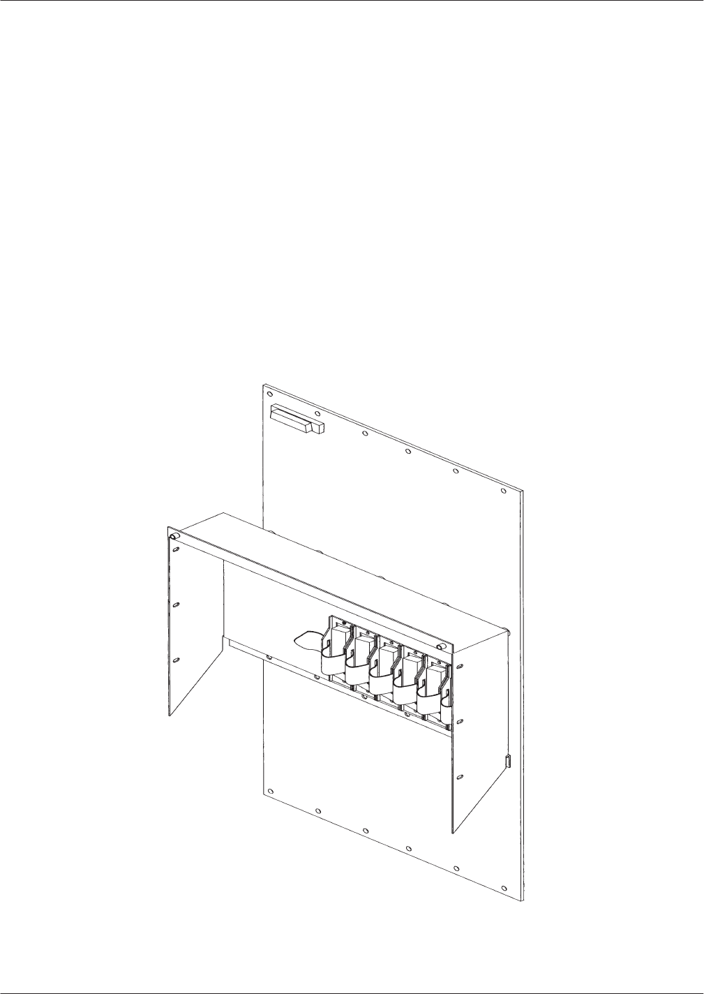
9-36
Installation and Maintenance
V
olume
Octel Overture 200/300 Serenade 3.0
PB60014–01
4. Once
the air filter is removed, rinse it in cold water until the water runs clear
.
5.
Shake out the excess water from the air filter
. The air filter should be dry before you reinstall it.
Installing the Air Filter
To
reinstall the air filter
, use the following procedures:
1.
Slide the air filter into the door in the way that you removed it. Make sure that the wavy side of the
filter material is against the door
.
2.
Once the air filter is in position, push the corners and the top and bottom edges of the air filter
against the velcro hold-downs.
3.
Close and lock the door to the cabinet.
Motherboard
Assembly
The
motherboard provides the communications bus for the VCU, CPU, and LIC printed circuit
assemblies as well as the d.c. power distribution for the disk drives. Figure 9-21 shows the motherboard
assembly.
Figure 9-21
Motherboard Assembly

Hardware
Replacement 9-37
Octel Overture 200/300 Serenade 3.0
PB60014–01
Caution!
Replacing
the motherboard assembly is a
complicated procedure. Replace it
only after
you
have confirmed that the motherboard is faulty
.
Do
not
disassemble the motherboard.
The motherboard can only be replaced as an assembly
. T
o replace the motherboard assembly
, you must
have access to both the front and rear of the Octel Overture 200/300 cabinet.
Removal and reinstallation procedures are separate for the Octel Overture 200 and Octel Overture 300,
because the procedures dif
fer for each message server
.
Caution!
Make sure to wear an an antistatic wrist strap before
attempting the following procedures.
Handle the motherboard assembly carefully; do not
drop it or bang it into other objects.
Never
set
anything on top of it.
Removing the Motherboard Assembly from the Octel Overture 200
To
remove the motherboard assembly, use the following procedures:
1.
Unlock and open the door of the cabinet.
2.
Put on an antistatic wrist strap. Connect it to an unpainted portion of the cabinet.
3. T
urn OFF the power supply unit. Refer to the Power Supply Unit Replacement section in this chapter
for details about turning OFF the power to the message server
.
4.
Disengage the cards in slots A1 through A9 from the motherboard. (The cards stay in the cabinet.)
Remove the floppy-diskette signal cable.
5.
Using a flat-bladed screwdriver
, loosen the two captive screws on the front of the power supply unit
and on the disk-drive assembly
. Disengage them from the backplane. (The power supply unit and the
disk-drive assembly stay in the cabinet.)
6.
Move to the back of the Octel Overture 200 cabinet, and label all cables attached to the motherboard,
so that they can be reattached in the same positions on the new motherboard.
7.
Disconnect the cables from the motherboard.
8.
Unplug the AC cord from the cabinet.
If the cabinet is d.c. powered,
disconnect the wiring from the d.c. power source at the DC inlet box.
Remove the DC inlet box from the back of the message server as shown in Figure 9-23.
9.
Remove the fan panel, following the instructions in the Octel Overture 200 Fan Panel Assembly
section in this chapter
.
10.
Disconnect the maintenance-port cable from the upper left hand corner of the motherboard.
11.
Using a Phillips head screwdriver
, remove the four screws that secure the bottom panel to the
cabinet, and remove the panel.
Cables that were disconnected from the motherboard in step 7 are fastened to the bottom panel with
cable ties. These cables can remain fastened.

9-38
Installation and Maintenance
V
olume
Octel Overture 200/300 Serenade 3.0
PB60014–01
12. Remove
the six screws that secure the motherboard to the cabinet from the sides of the motherboard
I/O panel.
13.
Remove the 18 screws that secure the motherboard to the cabinet; remove the motherboard.
14.
Refer to Figure 9-22 or Figure 9-23 and remove the hardware that secures the backplane power
harness to the motherboard. Use an 1
1/32 nut driver to remove the grounding hardware. Remove the
backplane power harness from the motherboard, so that it can be reinstalled on the new motherboard.
The hardware used to secure the backplane power harness to the motherboard is reused when
securing the harness to the new motherboard.
Installing a Motherboard Assembly in the Octel Overture 200
To
install the motherboard, use the following procedure:
Caution!
The motherboard must be aligned precisely to ensure
correct card engagement. T
o accomplish this, make
sure to follow the instructions exactly
.
1.
Install the backplane power harness from the old motherboard on the new motherboard. Refer to
Figure 9-22 or Figure 9-23 for correct installation.
2.
Remove the Option Control Chip (OCC) from the old motherboard and install it in the new
motherboard assembly. Refer to the Option Control Chip Replacement section in this chapter for
removal and installation procedures.
3.
Hold the new motherboard up to the cabinet, and install a screw in the top, center screwhole to hold
it in place.
4.
Install the remaining 17 screws along the top and bottom of the motherboard, so that the it is just
able to move, with a minimal amount of distance between the screwheads and motherboard.
Do not
tighten the screws yet.
5.
Install the six screws on the sides of the motherboard I/O panel, but do not tighten them at this time.
6.
Push only PCAs in slots A1 and A9, the power supply assembly
, and one disk-drive assembly into
the connectors on the motherboard.
Do not
tighten the power supply assembly
.
7. T
ighten the 18 screws at the top and bottom of the motherboard and the six screws on the I/O panel.
8.
Connect the maintenance port cable to the connector on the top left corner of the motherboard.
9.
Fasten the bottom rear panel with four screws (two short ones at the top, two long ones at the
bottom), and reconnect the cables as they were connected on the old motherboard.
10.
Replace the fan panel, following the instructions in the Octel Overture 200 Fan Panel Assembly
section in this chapter
.
If the cabinet is d.c. power
ed
, install the DC inlet box.
11. V
erify that the power supply unit is OFF. Attach the power cord.
If the cabinet is d.c. power
ed
, reconnect the wires from the d.c. power source to the DC inlet box.
Refer to Figure 9-23.
12.
Plug the remaining boards into the motherboard.

Hardware
Replacement 9-39
Octel Overture 200/300 Serenade 3.0
PB60014–01
13. Tighten
the two fasteners on the front of the power supply unit and disk-drive assembly
.
14. T
est the message server for correct operation by following the procedures in the Installation chapter
in this volume.
15.
Close and lock the door to the cabinet.
Removing a Motherboard Assembly from the Octel Overture 300
To
remove the Motherboard Assembly
, refer to Figure 9-24, Figure 9-25, and Figure 9-26, and use the
following procedures:
1.
Unlock and open the door of the cabinet.
2.
Put on an antistatic wrist strap. Connect it to an unpainted portion of the cabinet.
3. T
urn OFF the power supply unit. Refer to the Power Supply Unit Replacement section in this chapter
for details about turning OFF the power to the message server
.
4.
Disengage the cards in slots A1 through A14 from the motherboard. (The cards stay in the cabinet.)
Remove the floppy-diskette signal cable.
5.
Using a flat-bladed screwdriver
, loosen the two captive screws on the front of the power supply unit.
Disengage the motherboard from the backplane. (The power supply unit stays in the cabinet.)
6.
Move to the back of the Octel Overture 300 cabinet and label all cables attached to the motherboard,
so that they can be reattached in the same positions on the new motherboard.
7.
Disconnect the cables from the motherboard.
8.
Remove four screws that secure the top panel to the cabinet, and remove the panel.
9.
Disconnect the maintenance-port cable from the upper left hand corner of the motherboard assembly
.
10.
Remove the power filter assembly as described in the Octel Overture 300 Power
-Filter Assembly
Replacement section of this chapter
.
11.
Using a Phillips head screwdriver
, remove the four screws that secure the bottom panel to the
cabinet, and remove the panel.
Cables that were disconnected from the motherboard in step 7 are fastened to the bottom panel with
cable ties. These cables can remain fastened.
12.
Disconnect the power harness for the disk-drive backplanes (SCSI motherboard) at the motherboard.
Leave the harness ends connected to the disk-drive backplanes.
13.
Disconnect the two short flat cables from the motherboard. Leave the cables attached to the top
disk-drive backplane.
14.
Disconnect the fan power harness from the top disk-drive backplane.
15.
Remove the five screws that secure the motherboard to the cabinet from the sides of the motherboard
I/O panel.
16.
Remove the 18 screws that hold the top and bottom of the motherboard to the cabinet, and remove
the motherboard.
17.
Remove the power
-filter harness from the motherboard, so that it can be installed on the new
motherboard.
The hardware used to secure the harness to the motherboard (two screws, two nuts, and a
lockwasher) is reused when securing the harness to the new motherboard.

9-40
Installation and Maintenance
V
olume
Octel Overture 200/300 Serenade 3.0
PB60014–01
Installing the Motherboard Assembly in the Octel Overture 300
To
install the motherboard assembly
, use the following procedure:
Caution!
The motherboard must be aligned precisely to ensure
correct card engagement. T
o accomplish this, make
sure to follow the instructions exactly
.
1.
Install the filter power harness from the old motherboard on the new motherboard. Refer to
Figure 9-24 for correct installation.
2.
Remove the Option Control Chip (OCC) from the old motherboard and install it in the new
motherboard. Refer to the Option Control Chip Replacement section in this chapter for removal and
installation procedures.
3.
Hold the new motherboard up to the cabinet, and install a screw in the top, center screwhole to hold
it in place. Pass the power harness to the fan tray through the small, rectangular cutout in the bottom
of the motherboard.
4.
Install the remaining 17 screws along the top and bottom of the motherboard, so that it is just able to
move with a minimal amount of distance between the screwheads and the motherboard.
Do not
tighten screws yet.
5.
Install the five screws on the sides of the motherboard I/O panel, but do not tighten them at this time.
6.
Push only PCAs in slots A1 and A14 and the power supply assembly into the connectors on the
motherboard.
7. T
ighten the 18 screws at the top and bottom of the motherboard and the five screws on the
motherboard I/O panel.
8.
Plug the fan-tray harness into the top disk-drive backplane.
9.
Connect the two flat cables from the top disk-drive backplane to the motherboard.
10.
Connect the disk drive backplane power harness to the motherboard.
11.
Connect the maintenance port cable to the connector at the top left corner of the motherboard.
12.
Install the power filter assembly as described in the Octel Overture 300 Power
-Filter Assembly
Replacement section in this chapter
.
13.
Fasten the bottom rear panel with four screws, and reconnect the cables as they were connected on
the old motherboard.
14.
Fasten the top rear panel with four screws.
15. V
erify that the power supply unit is OFF. Attach the power cord.
If the cabinet is d.c. power
ed
, reconnect the wires from the d.c. power source to the power filter
assembly
. Refer to Figure 9-26.
16.
Plug the remaining boards into the motherboard.
17. T
ighten the two captive screws on the front of the power supply unit.
18. T
est the message server for correct operation by following the procedures in the Installation chapter
in this volume.
19.
Close and lock the door to the cabinet.
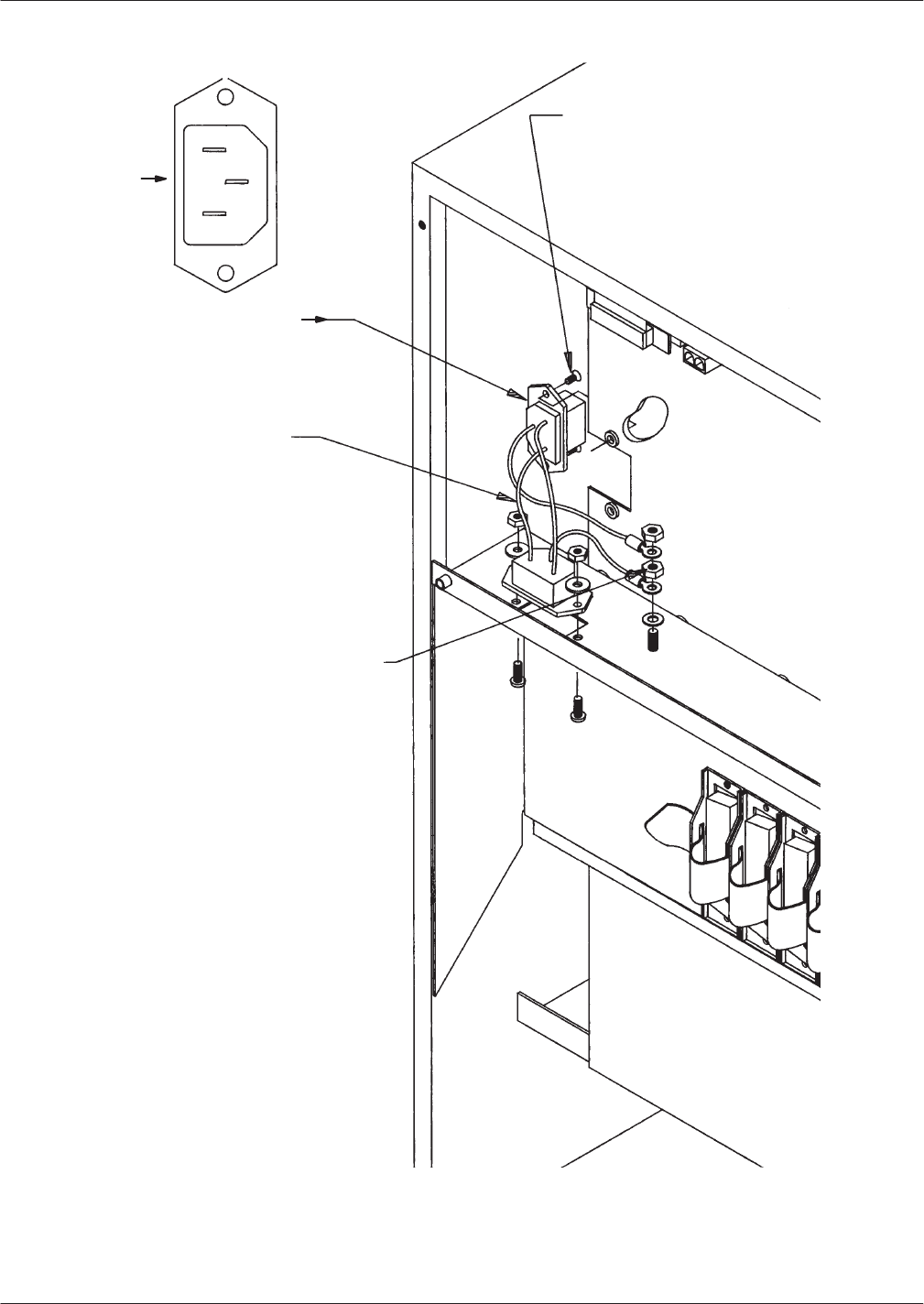
Hardware
Replacement 9-41
Octel Overture 200/300 Serenade 3.0
PB60014–01
Figure 9-22
A.C. Backplane Power Harness Installation for Octel Overture 200
Connector to Backplane
Mounting Screws
Connector
Backplane Power Harness
Front View
of Connector
HarnessĆGrounding
Hardware
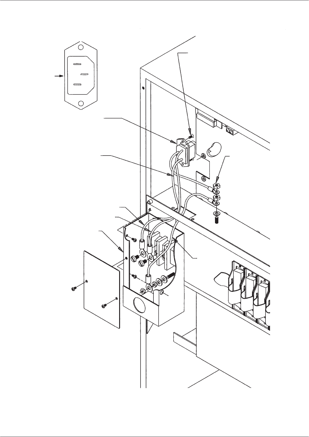
9-42
Installation and Maintenance
V
olume
Octel Overture 200/300 Serenade 3.0
PB60014–01
Figure 9-23
D.C. Backplane Power Harness Installation for Octel Overture 200
Front View
of Connector
Connector
Backplane Power Harness
Purple
Black
DC Inlet Box
Connector to Backplane
Mounting Screws
HarnessĆGrounding
Hardware
Green/Yellow
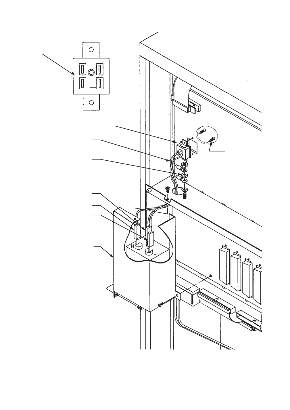
Hardware
Replacement 9-43
Octel Overture 200/300 Serenade 3.0
PB60014–01
Figure 9-24
Power-Filter Assembly for 120-V
ac and 240-V
ac Domestic Octel Overture 300
Connector
Mounting
Screws
PowerĆFilter
Assembly
HarnessĆGrounding
Hardware
BackplaneĆtoĆ
Filter Harness
Front View of
Connector
Green/Yellow
Brown
Blue
Connector
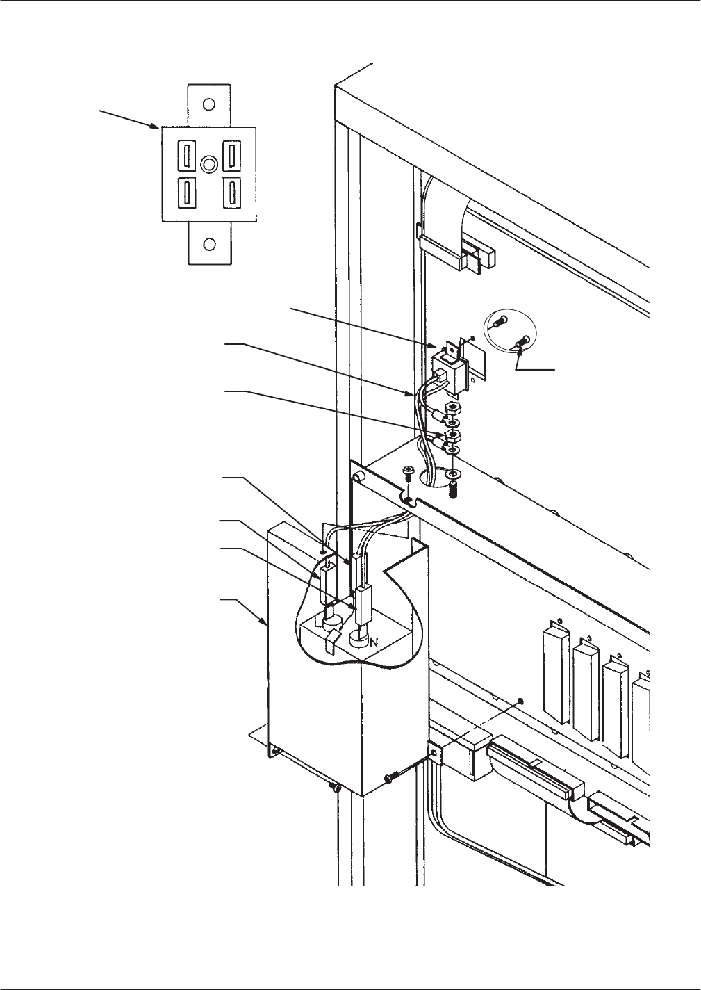
9-44
Installation and Maintenance
V
olume
Octel Overture 200/300 Serenade 3.0
PB60014–01
Figure 9-25
Power-Filter Assembly for 240-V
ac International Octel Overture 300
Front View of
Connector
Connector
Mounting
Screws
Power Filter
Assembly
HarnessĆGrounding
Hardware
BackplaneĆtoĆ
Filter Harness
Green/Yellow
Brown
Blue
Connector
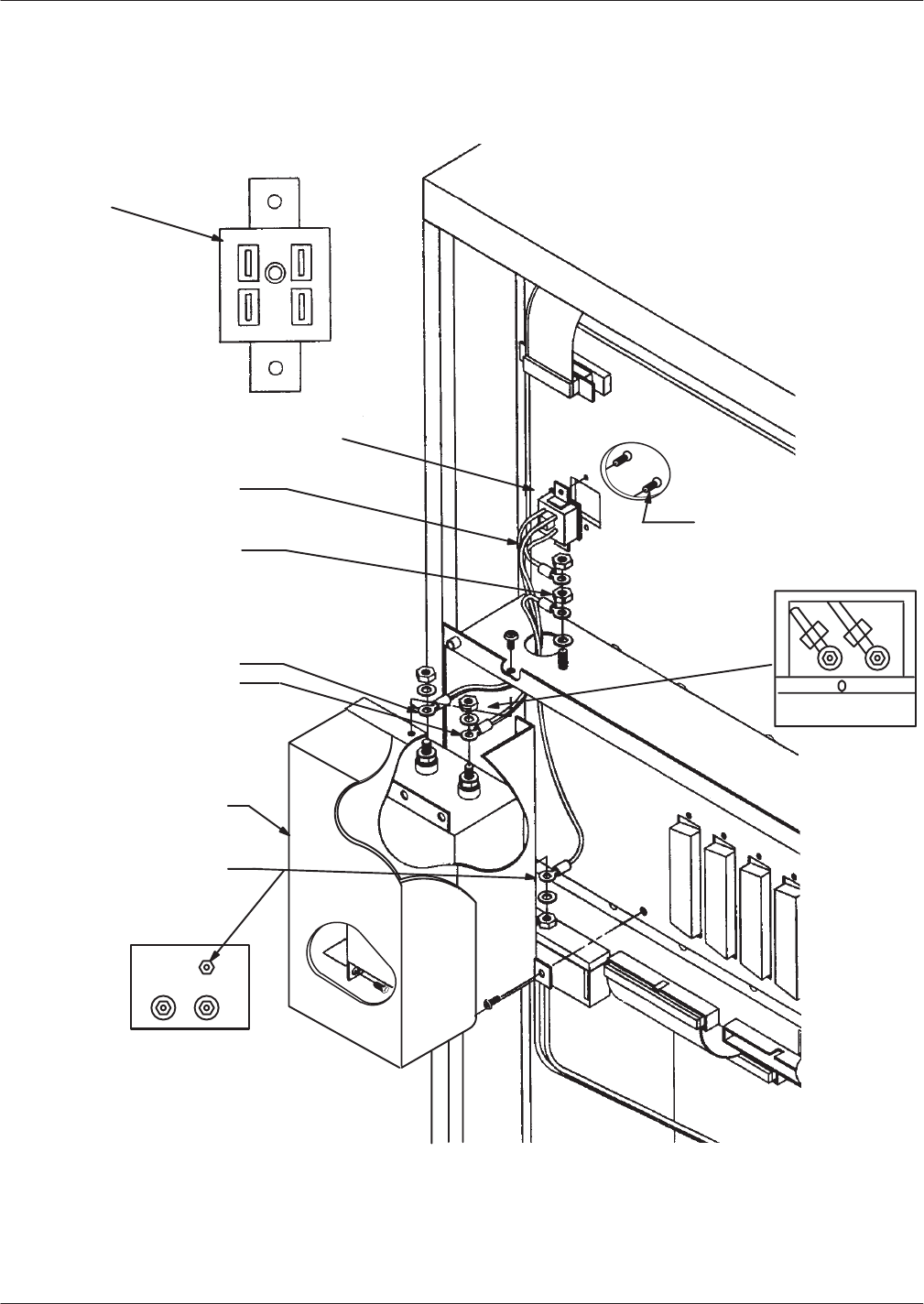
Hardware
Replacement 9-45
Octel Overture 200/300 Serenade 3.0
PB60014–01
Bottom View
of Filter
Figure 9-26
Power-Filter Assembly for 48-Vdc Octel Overture 300
Front View of
Connector
Connector
Mounting
Screws
DC Filter
Assembly
HarnessĆGrounding
Hardware
BackplaneĆtoĆ
Filter Harness
Green/Yellow
Black
Purple
Connector
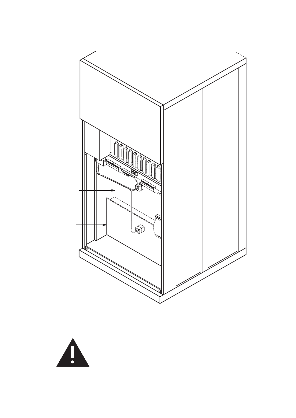
9-46
Installation and Maintenance
V
olume
Octel Overture 200/300 Serenade 3.0
PB60014–01
Octel
Overture 300 Disk-Drive Backplane Replacement
The
disk-drive backplanes provide communication and d.c. power buses from the motherboard to the
disk-drive assembly
. There are two disk-drive backplanes, one for shelf B and one for shelf C.
Figure 9-27
Octel Overture 300 Disk-Drive Backplanes
DiskĆDrive
Backplane,
Shelf B
DiskĆDrive
Backplane,
Shelf C
The following replacement procedures provide steps for removing and installing disk-drive backplanes.
Before proceeding, make sure to determine which backplane is faulty
.
Caution!
Disk-drive backplane are sensitive to static
electricity
.
Do not
attempt the following procedures
without wearing an antistatic wrist strap.
The disk drive backplane is sensitive to rough handling. Care should be taken to handle it as gently
as possible.

Hardware
Replacement 9-47
Octel Overture 200/300 Serenade 3.0
PB60014–01
Removing a Disk Drive Backplane from the Octel Overture 300
Use
the following procedure to remove a disk-drive backplane:
1.
Unlock and open the door of the cabinet.
2.
Put on an antistatic wrist strap. Connect it to an unpainted portion of the cabinet.
3. T
urn OFF the power supply unit. Refer to the Power Supply Unit Replacement section in this chapter
for details about turning OFF the power to the message server
.
4.
Using a flat-bladed screwdriver
, loosen the two captive screws on the front of each of the disk-drive
assemblies on the shelf that has the faulty backplane. Disengage each disk-drive assembly from the
backplane; the disk-drive assembly should stay in the cabinet.
5.
At the rear of the Octel Overture 300 cabinet, disconnect all cables attached to the motherboard.
Mark the cables so that they can be reattached at the same positions.
6.
Disconnect the power cord from the cabinet.
7.
Remove the four screws that secure the bottom panel to the cabinet, and remove the panel.
Cables that were disconnected from the motherboard in step 5 might be fastened to the bottom panel
with cable ties. These cables can remain fastened.
8.
Disconnect all harnesses and cables from the backplane being replaced. Make sure that the ends of
the harnesses and cables not directly attached to the backplane being replaced remain connected.
9.
If the shelf B disk-drive backplane is being removed, and the message server is equipped with a
load-resistor assembly
, remove the four screws and washers that secure the load-resistor assembly to
the message server
. Refer to Figure 9-28 to verify whether a load-resistor assembly is present.
10.
Remove the screws along the top and bottom edges of the backplane and remove it.
Installing a Disk Drive Backplane in the Octel Overture 300
Use
the following procedure to install a new disk-drive backplane:
Caution!
The backplane must be aligned precisely to ensure
that the disk-drive assembly is fully engaged with the
backplane. T
o accomplish this, follow the
instructions exactly
.
1.
Hold the new backplane up to the cabinet, and install a screw in the top, center screw hole to hold it
in place.
2.
If the shelf B backplane is being installed in a message server with a load-resistor assembly
, secure
the load-resistor assembly to the cabinet with four screws and washers, as shown in Figure 9-28 . Do
not tighten the screws.
3.
Install all of the screws along the top and bottom edges of the backplane, so that it is just able to
move, with only a small gap between the screwheads and the backplane.
4.
At the front of the cabinet, push each disk-drive assembly into its mating connector on the
backplane.
5. T
ighten all the screws on the top and bottom edges of the backplane.
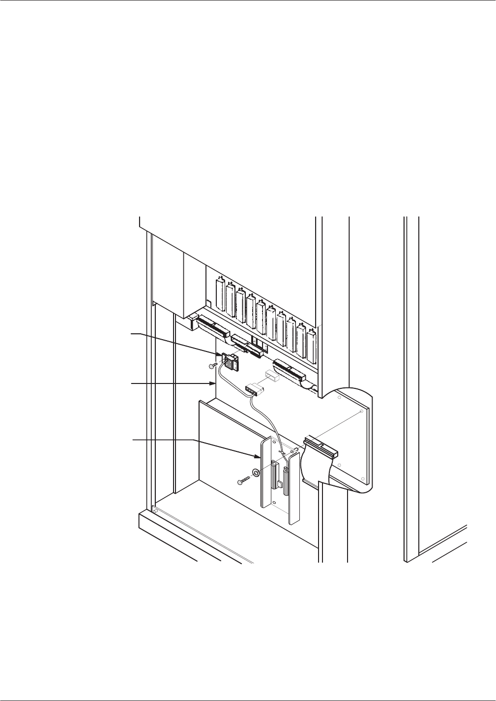
9-48
Installation and Maintenance
V
olume
Octel Overture 200/300 Serenade 3.0
PB60014–01
6. Reconnect
all harnesses and cables to the backplane.
7.
Fasten the bottom rear panel with four screws, and reconnect the cables as they were.
8. V
erify that the power supply unit is OFF . Attach the power cord.
9. T
ighten the fasteners on the front of each disk-drive assembly
.
10. T
est the message server for correct operation by following the procedures in the Installation chapter
in this volume. V
erify that the fans are spinning.
Octel
Overture 300 Load Resistor Assembly Replacement
If
the load-resistor assembly malfunctions, it must be replaced with a new one. Do not attempt to replace
or alter the load-resistor components or wire harness.
Figure 9-28
Cutaway V
iew of the Load-Resistor Assembly
Shelf B
Backplane
LoadĆ
Resistor
Assembly
FanĆ
Assembly
Connector

Hardware
Replacement 9-49
Octel Overture 200/300 Serenade 3.0
PB60014–01
Caution!
The
Octel Overture 300 is sensitive to static
electricity
.
Do not
attempt the following procedures
without wearing an antistatic wrist strap.
Removing the Load Resistor Assembly from the Octel Overture 300
Use
the following procedures to remove the load-resistor assembly:
1.
Unlock and open the door of the cabinet.
2.
Put on an antistatic wrist strap. Connect it to an unpainted portion of the cabinet.
3. T
urn OFF the power supply unit. Refer to the Power Supply Unit Replacement section in this chapter
for details about turning OFF the power to the message server
.
4.
Using a flat-bladed screwdriver
, loosen the two captive screws on the front of the fan assembly
.
5.
Pull the fan assembly forward about 1 inch. The fan assembly does not need to be removed from the
cabinet.
6.
At the rear of the cabinet, remove the four screws that hold the bottom panel to the back of the
cabinet, and set the panel aside.
7.
Locate the load-resistor assembly on the shelf B backplane (refer to Figure 9-28). Note that the
harness attached to the load-resistor assembly is also attached to the shelf B disk- drive backplane
and to the fan assembly
.
8.
Remove the three screws that secure the fan-assembly connector to the cabinet.
9.
Disconnect the harness where it plugs into the shelf B backplane.
10.
Remove four screws and washers that secure the load-resistor assembly sheet metal to the cabinet,
and set the load-resistor assembly aside.
Installing a Load Resistor Assembly in the Octel Overture 300
Use
the following procedures to install a load-resistor assembly:
1.
Put on an antistatic wrist strap. Connect it to an unpainted portion of the cabinet.
2. V
erify that the power supply switch is OFF
.
3.
Secure the load-resistor assembly sheet metal to the chassis with the four screws and washers, as
shown in Figure 9-28.
4.
Connect the load-resistor assembly/fan-assembly harness to the shelf B backplane.
5.
Secure the fan-assembly connector to the cabinet with three screws.
6.
Attach the bottom rear panel to the cabinet with four screws.
7.
Slide the fan assembly back into the cabinet, and secure it with the captive screws on the front of the
assembly.
8. T
urn ON the message server at the power supply unit switch, and check for correct message-server
operation. Make sure that the fans are spinning.
9.
Close and lock the door of the cabinet.

9-50
Installation and Maintenance
V
olume
Octel Overture 200/300 Serenade 3.0
PB60014–01
Octel
Overture 300 Power-Filter Assembly
The
power
-filter assembly is a unit that includes a power
-entry connection and a power
-line
EMI-suppression filter
. The power
-line filter varies with input power type; for domestic use the input
power is 120/240 Vac, and for international use it is 240 Vac or 48 Vdc.
The power
-filter assembly is replaced as a unit.
Do not
disassemble it in any way
.
Caution!
The power
-filter assembly is sensitive to static
electricity
.
Do not
attempt the following procedures
without wearing an antistatic wrist strap.
Removing the Power-Filter Assembly from the Octel Overture 300
To
remove the power-filter assembly
, use the following procedures:
1.
Unlock and open the door of the cabinet.
2. T
urn OFF the power supply unit.
3.
If the message server has an a.c. power source, disconnect the power cord at the power
-filter
assembly and set it aside.
If the cabinet is d.c.-powered, remove the cover from the DC filter assembly and disconnect the
wires from the power source at the terminal block mounted on the DC filter assembly
.
4.
At the rear of the cabinet, remove four screws that secure the top panel to the cabinet. Remove the
panel.
5.
Put on an antistatic wrist strap. Connect it to an unpainted portion of the cabinet.
6.
Remove the three screws that secure the power
-filter assembly to the cabinet.
7.
Disconnect the wires from the power
-filter assembly that lead to the motherboard assembly and set it
aside.
The AC power
-filter assembly does not require tools, whereas the DC filter assembly requires
an open-ended wrench to disconnect the wires.
Installing the Power-Filter Assembly in the Octel Overture 300
To
install the power
-filter assembly, use the following procedure:
1.
Connect the wires from the motherboard assembly to the power
-filter
, as shown in Figure 9-25 and
Figure 9-26, according to the voltage requirement for the message server
.
When fastening the filter harness to the DC filter assembly
, route the connecting wires
away
from the sharp edge.
2.
Secure the power
-filter assembly to the cabinet with three screws.
3.
Fasten the top panel with the four screws.
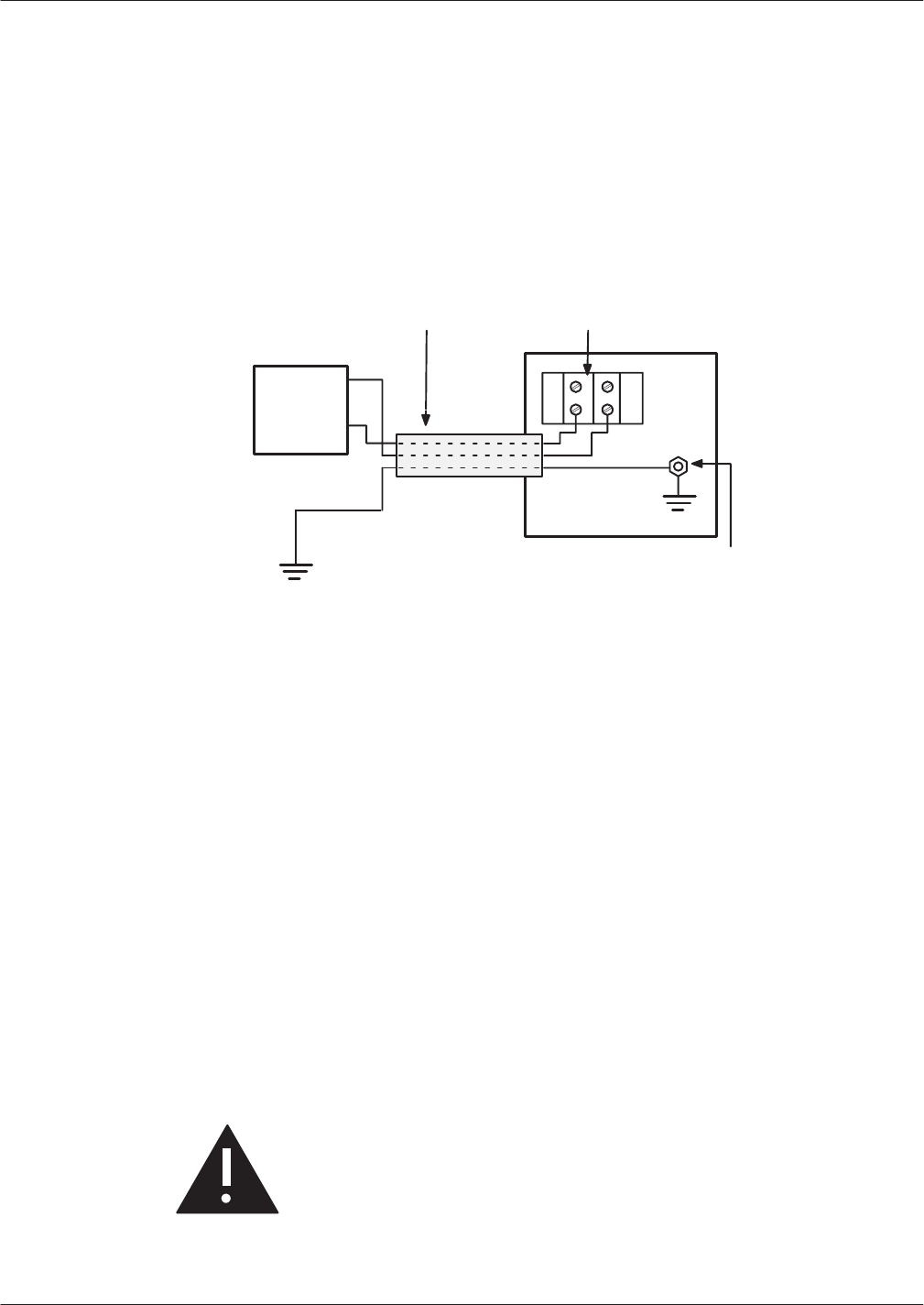
Hardware
Replacement 9-51
Octel Overture 200/300 Serenade 3.0
PB60014–01
4. If
the cabinet has an a.c. power source, plug the power cord into the power filter
.
If the cabinet is d.c.-powered, reconnect the wires from the power source to the terminal block, as
shown in Figure 9-29.
5. T
urn ON the power supply
.
6.
Close and lock the door of the cabinet.
7. T
est the message server for correct operation.
DC
Power
Source
Earth Ground
Conduit with three
10Ćgauge wires
Ground Stud
+–
–
+
Rear Panel
Terminal Block
Figure 9-29
Field W
iring for –48-Vdc Powered Octel Overture 300
AC-to-DC Power-Supply Conversion
Before
proceeding, read the instructions in the Installing the Octel Overture 200/300 W
ith a –48-Vdc
Power Supply Unit section, in the Installation chapter of this volume. Make sure that the material is
available to connect the cabinet to the –48-Vdc power source.
The Octel Overture 200/300 can be powered by either an a.c. or d.c. power source.
The Octel Overture 200 contains either an a.c. or d.c. version of the power supply unit to work with the
power source selected. The d.c. version of the message server requires an additional d.c. inlet box. T
o
convert the Octel Overture 200 from an a.c.-powered to a d.c.-powered message server
, use the Octel
Overture 200 instructions.
The Octel Overture 300 contains either an a.c. or d.c. version of the power supply unit and power
-filter
assembly to work with the power source selected. T
o convert the Octel Overture 300 from an
a.c.-powered to a d.c.-powered message server, use the Octel Overture 300 instructions.
Caution!
Damage to the message server might occur if
replacement procedures are not performed in the
order given.

9-52
Installation and Maintenance
V
olume
Octel Overture 200/300 Serenade 3.0
PB60014–01
Removing AC Subassemblies from the Octel Overture 200
This
conversion requires the Octel Overture 200 AC-to-DC power supply conversion kit, part number
740-6543-001, which contains the following:
DC power supply unit
DC inlet box
DC backplane harness
T
o remove the a.c. subassemblies, use the following procedures:
1.
Remove the a.c. power supply unit, following the instructions in the Removing the Power Supply
section in this chapter
.
2.
Remove the VCU and CPU cards from slots A8 and A9, respectively
.
3.
Discard the spare fuse attached to the side of the cabinet, located under the power supply unit.
4.
Disconnect the power cord at both ends, and set it aside.
5.
Remove the fan-panel assembly as described in the Removing the Fan Panel from the Octel Overture
200 section.
6.
Remove the AC backplane harness by removing the two screws that hold the connector in the
backplane, as shown in Figure 9-22. These screws can be accessed through the front of the cabinet.
Remove the hardware that secures the ground wires and the connector from the I/O panel. Pull the
harness out of the message server
.
Installing DC Subassemblies in the Octel Overture 200
To
install the d.c. subassemblies, use the following procedure:
1.
Remove the cover on the DC inlet box, as shown in Figure 9-23.
2.
Remove the two black screws that hold the I/O panel to the cabinet, and attach the d.c. inlet box to
the cabinet using two new screws.
3.
Install the d.c. backplane harness, as shown in Figure 9-23.
4.
Secure the fan panel to the cabinet, as described in the Installing the Fan Panel in the Octel Overture
200 section.
5.
Reinstall the VCU and CPU cards in slots A8 and A9, respectively
.
6.
Install the d.c. power supply unit following the instructions in the Installing the Power Supply Unit
section.
7.
Secure the new spare fuse to the side of the cabinet.
8.
Locate the message-server label on the base of the cabinet, at the rear. Mark the box on the label
indicating d.c. power. Remove the mark from the box indicating a.c. power
.

Hardware
Replacement 9-53
Octel Overture 200/300 Serenade 3.0
PB60014–01
Removing AC Subassemblies from the Octel Overture 300
This
conversion requires the Octel Overture 300 AC-to-DC power supply conversion kit, part number
740-6100-001, which contains the following:
DC power supply unit
DC filter assembly
DC backplane harness
T
o remove the a.c. subassemblies, use the following procedure:
1.
Remove the AC power supply unit, following the instructions in the Removing the Power Supply
section.
2.
Remove the VCU and CPU cards from slots A13 and A14, respectively
.
3.
Remove the AC Power Filter Assembly
, following the instructions in the Removing Power Filter
Assembly from the Octel Overture 300 section.
4.
Remove the a.c. filter
-to-backplane harness by removing the two screws that hold the connector in
the backplane, as shown in Figure 9-24 or Figure 9-25. These screws can be accessed through the
front of the chassis. Remove the nuts and washers that secure the ground wires. Pull the harness out
of the message server
.
Installing DC Subassemblies in the Octel Overture 300
To
install the d.c. subassemblies, use the following procedure:
1.
Install the d.c. filter
-to-backplane harness, as shown in Figure 9-26.
2.
Connect the wires from the backplane harness to the d.c. filter assembly
, as shown in Figure 9-26.
3.
Fasten the d.c. filter assembly to the cabinet, with three screws.
4.
Fasten the top panel to the cabinet, with four screws.
5.
Reinstall the VCU and CPU cards in slots A13 and A14, respectively
.
6.
Install the d.c. power supply unit, following the instructions in the Installing the Power Supply
section.
7.
Locate the message-server label on the base of the cabinet at the rear. Mark the box on the label
indicating d.c. power. Remove the mark from the box indicating a.c. power
.
Field Wiring to DC Power Source
Connect
the Octel Overture 200/300 to a d.c. power source as described in the Installation chapter
,
Installing the Octel Overture 200/300 With a –48-Vdc Power Supply Unit section.
Option Control Chip Replacement
The
Option Control Chip (OCC) is the component that controls the features that are installed on the Octel
Overture 200/300. The OCC assembly is an 8-pin integrated circuit inserted into a socket that is soldered
onto the motherboard, as shown in Figure 9-30 and Figure 9-31.
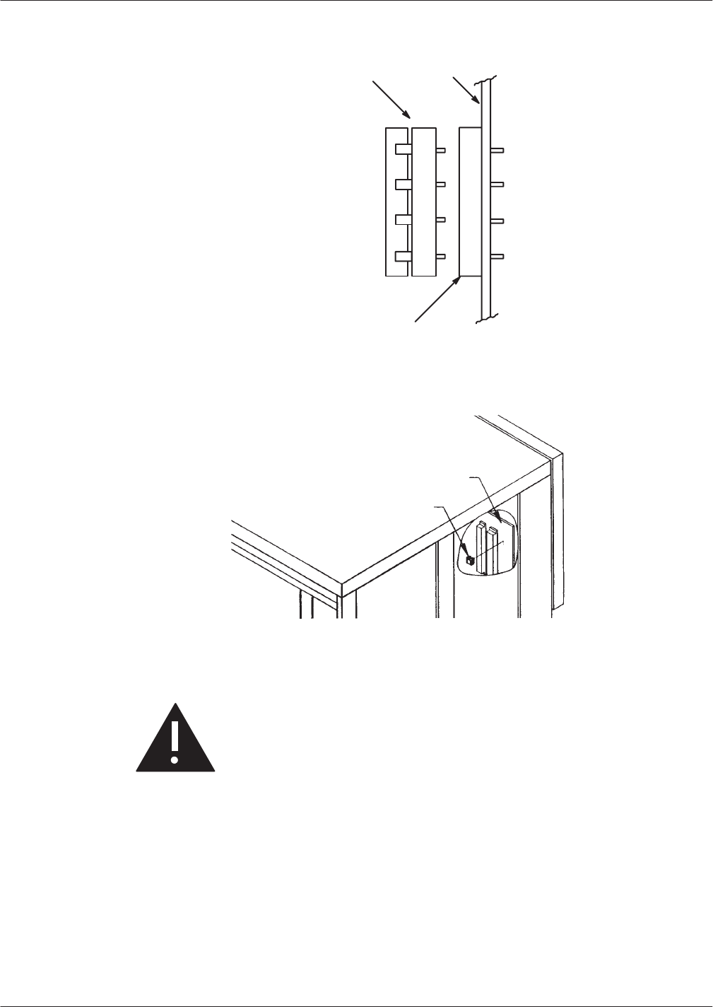
9-54
Installation and Maintenance
V
olume
Octel Overture 200/300 Serenade 3.0
PB60014–01
Figure 9-30
Option Control Chip (OCC) Assembly
Option Control
Chip Assembly
(including socket)
Motherboard
Socket fixed to Motherboard
Figure 9-31 Location of Option Control Chip (OCC) in the Octel Overture 200/300
Motherboard
Option Control Chip (OCC)
Caution!
The OCC assembly is sensitive to static electricity
and should be handled as little as possible.
Do not
attempt the following procedures without wearing an
antistatic wrist strap.

Hardware
Replacement 9-55
Octel Overture 200/300 Serenade 3.0
PB60014–01
Removing the OCC
The
OCC assembly should always be moved as a unit that includes the OCC integrated circuit and the
socket in which it is mounted. The two parts of the assembly should never be separated.
1.
Perform the procedure in the Removing the Power Supply section.
2.
After the power supply is removed, remove the CPU and the VCU cards. Follow the instructions in
the Printed Circuit Assembly Replacement section.
3.
Locate the OCC assembly next to the top power supply connector on the motherboard. Using an IC
puller
,
carefully
pry the entire OCC assembly from the motherboard. If a pin is broken or bent
during removal, a new OCC must be ordered.
4.
Place the OCC assembly on an antistatic foam pad.
Installing the OCC
To
install the OCC assembly
, use the following procedures:
1.
Install the new OCC assembly next to the top power supply connector on the motherboard. Pin 1 on
the OCC assembly must be up.
2.
Replace the CPU and the VCU cards, as described in the Printed Circuit Assembly Replacement
section of this chapter
.
3.
Replace the power supply unit, as described in the Power Supply Unit Replacement section of this
chapter.
4. T
urn ON the message server
, and test for correct operation.
5.
Close and lock the door of the cabinet.

9-56
Installation and Maintenance
V
olume
Octel Overture 200/300 Serenade 3.0
PB60014–01
9.3 MESSAGE
SER
VER ASSEMBL
Y DESCRIPTIONS
AND PART
NUMBERS
Octel
Overture 200 Assemblies
Assemblies
used in the Octel Overture 200 are as follows:
Assembly Part
Number
System
Motherboard, Board Assembly
740-6503-001
CPU, Board Assembly
300-6039-001
VCU, Board Assembly
300-6001-004
90- to 132-V
ac Power Supply Assembly
740-6504-001
180- to 260-V
ac Power Supply Assembly
740-6505-001
42- to 60-Vdc Power Supply Assembly
740-6506-001
AC-to-DC Power Supply Conversion Kit
740-6543-001
Hard-Disk Drive, 500 MB (0 hour drive)
740-6632-002
Hard-Disk Drive, 1.0 GB (0 hour drive)
740-6631-002
Hard-Disk Drive, 2.0 GB (0 hour drive)
740-6633-002
Maintenance Port Cable
520-6502-001
Fan Power Harness
530-6501-001
Fan Panel Assembly
740-6502-001
Air Filter
840-6507-001
Octel
Overture 300 Assemblies
Assemblies
used in the Octel Overture 300 are as follows:
Assembly Part
Number
System
Motherboard, Board Assembly
, Shelf A
740-6003-001
SCSI Motherboard, Board Assembly
, Shelf B
300-6006-001
SCSI Motherboard, Board Assembly
, Shelf C
300-6005-001
CPU, Board Assembly
, 8 megabytes
300-6039-001
VCU, Board Assembly
300-6001-004
120-V
ac Power Supply Assembly
740-6016-001
240-V
ac Power Supply Assembly
740-6017-001
-48-Vdc Power Supply Assembly
740-6027-001
AC-to-DC Power Supply Conversion Kit
740-6100-001
Hard-Disk Drive, 500 MB (0 hour drive)
740-6632-002
Hard-Disk Drive, 1.0 GB (0 hour drive)
740-6631-002
Hard-Disk Drive, 2.0 GB (0 hour drive)
740-6633-002
Floppy Drive Assembly
740-6010-001
SCSI Bus Jumper Cable
520-6001-001
Maintenance Port Cable
520-6003-001
Fan Power Harness
530-6001-001

Hardware
Replacement 9-57
Octel Overture 200/300 Serenade 3.0
PB60014–01
Assembly Part
Number
120-/240-Vac
Filter
-to-Backplane Harness
530-6009-001
48-Vdc Filter
-to-Backplane Harness
530-6021-001
Disk Power Harness
530-6010-001
Fan T
ray Assembly
740-6002-001
Air Filter
840-6013-001
Load Resistor Assembly
740-6128-001
120-V
ac Power Filter Assembly
740-6006-001
240-V
ac Power Filter Assembly
, Domestic
740-6028-001
240-V
ac Power Filter Assembly
, European
740-6031-001
Octel
Overture 200/300 Assemblies
Assemblies
used in both the Octel Overture 200 and the Octel Overture 300 are as follows:
Assembly Part
Number
Option
Control Chip (OCC), Replacement
FK 90004
Line Card, Board Assembly
, U. S., Canada, Mexico, 4-port
300-6002-001
Line Card, Board Assembly
, U. S., Canada, Mexico, 8-port
300-6032-001
Line Card, Board Assembly
, U.S, Canada, Mexico, 16-port
300-6054-001
Line Card, Board Assembly
, United Kingdom, 4-port
300-6002-002
Line Card, Board Assembly
, United Kingdom, 8-port
300-6032-002
Line Card, Board Assembly
, United Kingdom, 12-port
300-6056-002
Line Card, Board Assembly
, United Kingdom, 16-port
300-6054-002
Line Card, Board Assembly
, France, 4-port
300-6044-001
Line Card, Board Assembly
, Germany
, 4-port
300-6044-005
Line Card, Board Assembly
, Netherlands, 4-port
300-6002-009
Line Card, Board Assembly
, Netherlands, 8-port
300-6032-009
Line Card, Board Assembly
, New Zealand, Australia, 4-port
300-6002-011
Line Card, Board Assembly
, New Zealand, Australia, 8-port
300-6032-011
T
elemarketing Line Card, Board Assembly
, 8-port
300-6032-003
T
elemarketing Line Card, United Kingdom, 8-port
300-6032-004
T
elemarketing Line Card, New Zealand, Australia, 8-port
300-6032-012
Direct Access Card (DAC)
300-6027-001
Direct Access Card (DAC), New Zealand, Australia, 4-port
300-6027-011
Fax Application Processor
, 4-channel
300-6037-002
Fax Application Processor
, 8-channel
300-6037-003
LAN card
300-6049-001
Northern T
elecom Integration Card (SLIC)
300-6009-001
A
T&T Integration Card (A
TTIC) 300-6018-001
ROLM Integration Card (RIC)
300-6025-001
Mitel Integration Card (MIC)
300-6020-001
Serial Integration Card for the Meridian 1 (SIC8)
300-6040-001
APIC Integration Card for A
T&T Systems
300-6058-003
NPIC Integration Card for Northern T
elecom 300-6058-004

Octel
Overture 200/300 Serenade 3.0
PB60014–01
10
DIGITAL
TRUNK INTERF
ACE
CARD
(DTIC)
Chapter
Contents
10.1 Digital
T
runk Interface Card (DTIC) Overview 10-1.
. . . . . . . . . . . . . . . . . . . . . . . . . . . . . . . . . . . . . . . . . . . . . . . . . .
DTIC
Hardware
10-1.
. . . . . . . . . . . . . . . . . . . . . . . . . . . . . . . . . . . . . . . . . . . . . . . . . . . . . . . . . . . . . . . . . . . . . . .
10.2 How
to Configure the DTIC
10-3.
. . . . . . . . . . . . . . . . . . . . . . . . . . . . . . . . . . . . . . . . . . . . . . . . . . . . . . . . . . . . . . . . .
System
Parameters
10-3.
. . . . . . . . . . . . . . . . . . . . . . . . . . . . . . . . . . . . . . . . . . . . . . . . . . . . . . . . . . . . . . . . . . . .
Class of Service 10-4.
. . . . . . . . . . . . . . . . . . . . . . . . . . . . . . . . . . . . . . . . . . . . . . . . . . . . . . . . . . . . . . . . . . . . . . .
LSP
T
able 10-4.
. . . . . . . . . . . . . . . . . . . . . . . . . . . . . . . . . . . . . . . . . . . . . . . . . . . . . . . . . . . . . . . . . . . . . . . . . . . .
SLOTS
T
able 10-4.
. . . . . . . . . . . . . . . . . . . . . . . . . . . . . . . . . . . . . . . . . . . . . . . . . . . . . . . . . . . . . . . . . . . . . . . . .
10.3 Troubleshooting
and Maintenance
10-10.
. . . . . . . . . . . . . . . . . . . . . . . . . . . . . . . . . . . . . . . . . . . . . . . . . . . . . . . . . .
Diagnostics 10-10
. . . . . . . . . . . . . . . . . . . . . . . . . . . . . . . . . . . . . . . . . . . . . . . . . . . . . . . . . . . . . . . . . . . . . . . . . . .
DTIC
Not Up
10-11.
. . . . . . . . . . . . . . . . . . . . . . . . . . . . . . . . . . . . . . . . . . . . . . . . . . . . . . . . . . . . . . . . . . . . . . . . .
Call
into System, Phone Rings but Is Never Answered
10-19.
. . . . . . . . . . . . . . . . . . . . . . . . . . . . . . . . . . . . .
System Answers but V
oice Quality Is Poor
10-19.
. . . . . . . . . . . . . . . . . . . . . . . . . . . . . . . . . . . . . . . . . . . . . . .
System Answers but Pops or Buzzes 10-19.
. . . . . . . . . . . . . . . . . . . . . . . . . . . . . . . . . . . . . . . . . . . . . . . . . . . .
Modem
Connection Has Garbage Characters
10-19.
. . . . . . . . . . . . . . . . . . . . . . . . . . . . . . . . . . . . . . . . . . . .
Ports
on the DTIC Configured for Ringing but Do Not Answer Calls
10-19.
. . . . . . . . . . . . . . . . . . . . . . . . . .
DTIC
Still Does Not Operate Correctly
10-20.
. . . . . . . . . . . . . . . . . . . . . . . . . . . . . . . . . . . . . . . . . . . . . . . . . . .
Figure
10-1 DTIC
Component Layout
10-2.
. . . . . . . . . . . . . . . . . . . . . . . . . . . . . . . . . . . . . . . . . . . . . . . . . . . . . . . . . . . . . . . . . . .

DTIC
10-1
Octel Overture 200/300 Serenade 3.0
PB60014–01
10.1 DIGITAL
TRUNK INTERF
ACE CARD (DTIC) OVER
VIEW
The DTIC is applicable only to specific Octel channels
in Europe and is available only through those channels.
This
chapter contains information specific to the digital trunk interface card (DTIC). Included are details
about hardware, installation, configuration, and maintenance and troubleshooting. The DTIC is not
documented elsewhere in this manual.
The DTIC is a 30-port line card designed to interface an
Octel Overture 200/300 to E1 trunks.
E1 trunks are the European “building block” standard for Wide Area Network (W
AN) communication.
E1 is specified by CCITT and also standardized by ETSI. An E1 trunk can carry 30 simultaneous phone
calls plus signaling information. A port carries voice and data for calls. Each port can be viewed as a
“virtual” telephone connection where each end is either on hook or of
f hook.
For the DTIC to operate correctly
, two tables must be configured in the Octel Overture 200/300: the
SLOTS T
able and the SYSTEM P
ARAMETER T
able. An LSP T
able is also used by the Octel Overture
200/300. A COS must be configured for each of the 30 DTIC ports.
DTIC
Hardware
The
DTIC consists of two major processing components: the control processor (CP) and five digital
signal processors (DSPs). Refer to Figure 10-1 showing the layout of the primary components on the
card.
T
o connect the Octel Overture 200/300 to the PBX, use two 75-ohm coax cables. Be sure that the sw1
and sw2 switches on the card are set correctly to 75 ohms and 120 ohms for Germany
. Refer to
Figure 10-1.
Three kits are available.
Kit Name
Kit Part Number
Included in Kit
75 ohm DTIC–E1 Kit
740-6254-002
DTIC–E1 card, DTIC-E1 adapter (BNC version),
grounding strip, EMI suppression material, and
fastening hardware (does not include cables)
120 ohm DTIC–E1 Kit
740-6254-003
DTIC–E1 card, grounding strip, EMI suppression
material, and fastening hardware (does not include
cables)
DTIC–E1 Grounding
Strip Materials Kit
740-6255-001
Grounding strip and fastening hardware (does not
include cables)
Refer to the Installation chapter, DTIC Pin Assignment section, for the 50-pin telco connector pin
assignments for the DTIC. Refer to the Hardware Replacement chapter, DTIC Replacement section, for
the procedure for replacing/installing a DTIC.
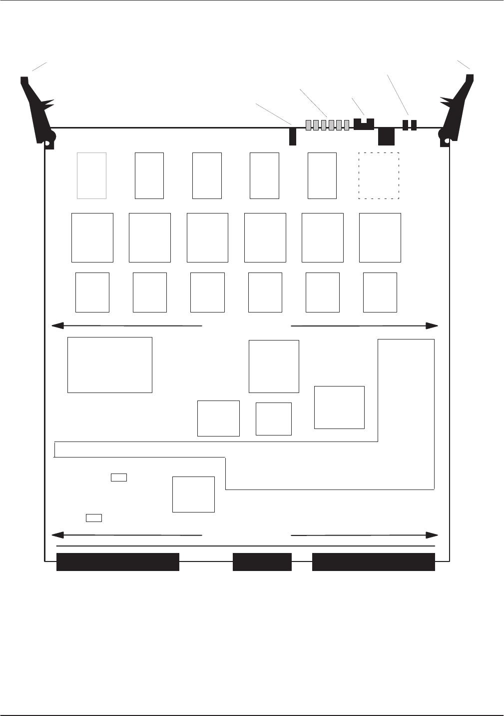
10-2
Installation and Maintenance
V
olume
Octel Overture 200/300 Serenade 3.0
PB60014–01
Card
Ejector
Card Stiffener
Status
LEDs
Card Ejector
Figure 10-1 DTIC Component Layout
Card Stiffener
Power/run
LEDs
Connector P3 Connector P2 Connector P1
Connector
P4
WDT
jumper
DSP
PGA
DSP
memory
DSP
DSP
PGA
DSP
memory
DSP
DSP
PGA
DSP
memory
DSP
DSP
PGA
DSP
memory
DSP
DSP
PGA
DSP
memory
DSP
Reserved
for 6th
DSP
PGA
DSP
memory
DSP
CP memory PGA
SM
Boot
ROM
Trunk
Framer
Trunk
Framer
sw2
75 ohm 120 ohm
sw1
75 ohm 120 ohm

DTIC
10-3
Octel Overture 200/300 Serenade 3.0
PB60014–01
10.2 HOW
T
O CONFIGURE THE DTIC
For
the DTIC to operate correctly, the Octel Overture 200/300 for the DTIC must be configured correctly
.
The major items for configuration are the following:
System Parameters
COS
SLOTS Table
The correct LSP T
able must be selected during configuration of the SLOTS T
able. The LSP
T
able, with the name ACULAB, first must be added and configured at a password level higher
than Maintenance level.
Special information regarding integration and configuration, including information about the
LSP T
able, is provided in the integration document DPNSS–ACULAB–03/96.
System
Parameters
Several
system parameters must be properly set to allow the DTIC to work correctly:
System Parameter 3 — PBX TYPE and PBX MODEL.
Set the PBX type and PBX model to the correct settings.
System Parameter 9 — FLASH TIME (MSEC).
Set the flash time to 130 msec.
System Parameter 13
Set the five parts of this parameter
. The settings are PBX dependent.
TRANSFER INITIATE CODE
RECONNECT CODE AFTER NO-ANSWER
RECONNECT CODE AFTER BUSY
RECONNECT CODE AFTER F
AST BUSY
TRANSFER COMPLETE CODE
System Parameter 51 — RS-232 INTEGRA
TED WITH PBX.
Does not have to be integrated to work. The setting is site dependent.
System Parameter 77 — PBX PROVIDES MOMENT
AR
Y DISCONNECT
.
Set to
YES.
System Parameter 1
17 — RINGBACKS BEFORE ANSWERING AX POR
T.
Set to
3
,
4
, or
5
for integrated systems or to
0
if not integrated. This setting is site specific and
depends on customer preference.

10-4
Installation and Maintenance
V
olume
Octel Overture 200/300 Serenade 3.0
PB60014–01
System
Parameter 175 — POR
T NUMBER FOR CALL RECORDS T
O FIRST POR
T
.
These settings are site specific and depend on the numbering of PBX extensions. The following is an
example of settings for the four parts of this parameter:
Number of digits in the extension number fields to
5
Number of digits in the port number field to
3
Fill character to
0
(zero)
Port number used in call records to
1
System Parameter 198 — PCM ENCODING FOR THE SYSTEM.
Set to
1
, for A-law
.
V
oice data is encoded, in the E1 environment, into 8 bit numbers (called octets) that are sent 8000
times per second for each port. This process of sampling and encoding analog
voice to these octets is
called Pulse Code Modulation (PCM). PCM uses two standard algorithms for conversion: A-law
,
which is used primarily in Europe, and U-law, which is used in North America. If DTIC voice quality
sounds consistently bad but still recognizable, the DTIC could be operating with the wrong PCM law
.
T
o correct this low voice quality
, change the PCM law and restart the message server
.
⇒Important:
If
a DTIC card is configured for A-law
, 4- or 8-port line cards cannot be used:
T
o receive fax calls
For modem connection using the
command
Class of Service
A
COS must be configured for each of the 30 DTIC ports. Assign attributes as required. Refer to the
Configuration
volume, COS chapter
.
LSP Table
LSP
tables are preconfigured and exist in the system. The LSP T
able defines control parameters for
dif
ferent DSP-based line/trunk interface cards and the DSP-based integration cards. Each LSP T
able has
fields that define values for control parameters needed for correct operation of the card. These values are
downloaded to the card when it boots up.
In UPDA
TE, the LSP T
ables can be listed by the command
LIST LSP.
If problems exist because of an
LSP T
able configuration, information about these parameters is useful if it is necessary to call technical
support for help.
SLOTS Table
The
slot in which a DTIC is to be installed must be added to the SLOTS T
able. Adding a slot for a DTIC
is similar to adding a slot for other line cards. However
, there are some questions pertaining specifically
to the DTIC.
Slots can be skipped, as for any line cards. However
, the grounding strip is for only the first seven slots.
W
ith Capacity on Demand, the number of ports for the DTIC are purchased as required.
After the slot is configured, the system must be restarted for the DTIC to become operational.

DTIC
10-5
Octel Overture 200/300 Serenade 3.0
PB60014–01
Configuring Slots for the DTIC
The
DTIC card is physically connected to a PBX extension (a single line) via two 75-ohm coax cables to
support 30 ports. The PBX directs calls to the message server for answering.
The SLOTS T
able contains information about each port on the DTIC card.
Each port connected to a PBX extension can be configured to handle calls dif
ferently
. For non-integrated
systems, the port extensions must be set up in one or more hunt groups in the PBX. Each hunt group can
be configured to handle calls dif
ferently.
The following example shows only eight ports. The DTIC can have up to 30 ports configured.
SLOT CARD TYPE PORT EXTENSION # COS MODE OUTCALL TEST SYS
–––– ––––––––– –––– ––––––––––– ––– –––– ––––––– –––– –––
4 DTC17–E1 1 254 AX NO NO 7
2 254 AX NO NO 8
3 254 AX NO NO 9
4 254 AX NO NO 10
5 254 AX NO NO 11
6 254 AX NO NO 12
7 254 AX NO NO 13
8 254 AX NO NO 14
LSPTAB table: ACULAB
SECONDARY SYNC RECEIVER OF CLOCK
The
following describes the valid or invalid entries for the SLOTS T
able fields:
Enter the slot number to be configured — slots 1–6 for the Octel Overture
200 and slots 1–7 for the Octel Overture 300.
Because the grounding strip used for the DTIC is only for seven
slots, in ef
fect the slots available for the Octel Overture 300 are
slots 1–7.
Enter the number for a DTIC card —
23–DTC17–E1.
Configure the ports in consecutive order
. Specifies the port (channel)
number on a card. DTIC cards have 30 channels each. If two DTIC cards
are installed in slots 1 and 2, the channel numbers on the card in the
second slot start with port 31.
Enter the PBX extension number connected to each message server port. A
mailbox extension number
cannot
be the same as a port extension number
.
Enter the COS for each port on the card. Directs the message server to
other system tables for the days and times to activate features and where to
get further instructions for handling the call.
Assign port/trunk COS in descending order
, starting with the
highest-numbered COS.
SLOT
CARD
TYPE
PORT
EXTENSION #
COS

10-6
Installation and Maintenance
V
olume
Octel Overture 200/300 Serenade 3.0
PB60014–01
Enter
the Answering Mode. Must be either Primary Answer (AX),
Secondary Answer (CX), or Message Center (MX). Determines how the
message server handles the call when that port answers. For further details
on answering modes, refer to the
Pr
oduct Description
volume, General
Description chapter, and to the
Configuration
volume, Slots T
able chapter
,
Line Cards section.
Enter YES or NO to enable or disable message waiting, network message,
and alarm calls. Specifies whether the port may place a call. Provide this
information for each port on the card.
For message waiting notification or alarm outcalls, multiple calls
can be placed simultaneously
.
Some PBXs require that the same port/extension activate and
deactivate the message waiting lamp. T
o do this, define System
Parameter 106 — LAMP MESSAGE W
AITING POR
T
, with the
port number to use.
Nonintegrated Systems.
In most cases, allow
all
ports to make outcalls.
When all ports are defined as YES, the message server only makes
outcalls when no more than
of the ports are in use. This leaves ports
available for incoming calls. If NO is defined for any ports, all ports
defined as YES are used for outcalls, even when more than
are in use.
It is recommended that NO for OUTCALL be used only for special
applications.
Integrated Systems.
If eight or fewer ports are configured, the message
server makes outcalls when at least two ports are idle. If 9–32 ports are
configured, the message server makes outcalls when at least three ports are
idle. If more than 32 ports are configured, the message server makes
outcalls when at least four ports are idle.
Enter 1, 2, or 3 to specify that this card is the primary
, secondary
, or
tertiary system clock sync source or N that the card is not used as a clock
sync source.
If no other cards (PIC or other DTIC) have been selected as the primary
clock sync source, enter 1. If another card has been selected as the primary
clock sync source, enter 2. If other cards have been selected as the primary
and secondary clock sync source, enter 3. Otherwise, enter N.
If the card selected as the primary clock sync source has problems (for
example, the clock is lost), the system CPU switches to the secondary
clock sync source. If the secondary fails, the CPU switches to the tertiary
clock sync source. If the tertiary fails, the CPU uses its own internal but
less accurate clock crystal.
Designates the system port number for each port on a DTIC card. The port
numbers are allocated sequentially by the system.
MODE
OUTCALL
SYNC
SYS

DTIC
10-7
Octel Overture 200/300 Serenade 3.0
PB60014–01
Enter
the number to specify the LSP T
able to be referenced for this slot.
The LSP T
able for this DPNSS integration first must be added and
configured at a password level higher than Maintenance level. If the
ACULAB LSP T
able does not appear in the list of LSP T
ables,
contact T
echnical Support to add the table and configure it
correctly.
Adding or Modifying a DTIC Card
When
adding DTIC cards, ports can be added if the number of used ports is less than the number of
authorized ports. The message server checks to see that the number of ports configured does not exceed
the maximum number of DSP ports purchased.
After the card type is entered, the LSP T
able must be entered. The name of the LSP T
able to choose is
ACULAB. After the LSPT
AB table is chosen, enter information about each port, including extension
number
, COS, answer mode (AX, CX, MX), if the port is used for message waiting and network
outcalling (Y/N), and test channel (Y/N).
The LSP T
able for this DPNSS integration first must be added and configured at a password level
higher than Maintenance level. If the ACULAB LSP Table does not appear in the list of LSP
T
ables, contact T
echnical Support to add the table and configure it correctly
.
LSPTAB

10-8
Installation and Maintenance
V
olume
Octel Overture 200/300 Serenade 3.0
PB60014–01
.A SLOT
Enter SLOT NUMBER to ADD.
Enter empty line when done.
ADD:2
6 –LIC4 5 –MITEL 2 –SLIC 8 –ACP
7 –DAC4 50–PICROLM 3 –RIC 16–FAX8
10–LIC8 51–PICATT 4 –ATTIC 17–FAX4
11–TLC8 52–PICNT 13–SIC8 22–LAN
18–LIC4I
23–DTC17–E1
25–DTC17–ISDN
26–DLC16
33–ILIC12FR
34–ILIC12UK
35–ILIC12JP
37–ILIC12GR
Enter Card Type.
SLOT 2 :23
Enter LSP table to be referenced for this slot.
0–DEFAULT 6–IL12US_S 12–DL1690 18–IL12UK_C 24–PIC_NT
1–IL12FR_S 7–DL16FR 13–DPNSS_CB 19–IL12FR_C 25–PIC_ROLM
2–IL12GE_S 8–T1 14–DL16UK_C 20–IL12GE_C 26–DL16SNG
3–DL16US 9–MD110–E1 15–DL16NTH 21–IL12US_C 27–DL16OS
4–DL16AU 10–DL16UK_S 16–DL16TOSH 22–EUROISDN
5–DL16GE 11–IL12UK_S 17–DL16TIE 23–PIC_AT&T
(Empty line = 0)
MOD:9
Should this card be:
(1 – PRIMARY
2 – SECONDARY
3 – TERTIARY
N – no ) sync receiver of the master clock?
(1–3, N. Empty line = N):2
Enter information for each PORT.
Enter as: EXTENSION NUMBER connected to each port (1–8 digits),
CLASS–OF–SERVICE (0–254), ANSWER MODE (AX, CX, MX), USE PORT FOR
MESSAGE WAITING AND NETWORK OUTCALLING (Y/N)
1: N,254,AX,N
2: N
3: N
.
.
.
28: N
29: N
30: N
The
number of the ACULAB LSP T
able might not be 49, as it is in this example, because this LSP
T
able is not part of the Serenade software. If the ACULAB LSP T
able does not appear in the list of
LSP T
ables, contact T
echnical Support to add the table and configure it correctly
.

DTIC
10-9
Octel Overture 200/300 Serenade 3.0
PB60014–01
Modifying
a DTIC card in the SLOTS T
able is similar to adding a DTIC.
.M SLOT
Enter slot number to MODIFY
Enter empty line when done.
MOD:5
6 –LIC4 2 –SLIC 8 –ACP
7 –DAC4 3 –RIC 17 –FAX4
10 –LIC8 4 –ATTIC 16 –FAX8
11 –TLC8 13 –SIC8 22 –LAN
18 –LIC4I
5 –MITEL
23 –DTC17–E1
26 –DLC16
50 –PICROLM
51 –PICATT
52 –PICNT
33 –ILIC12FR
34 –ILIC12UK
35 –ILIC12JP
37 –ILIC12GR
Enter card type.
SLOT 5:23
Enter LSPTAB table to be referenced for this slot.
0–DEFAULT
1–ILC12_FR
2–ILC12_GE
3–DLC16_US
4–DLC16_AU
5–DLC16_GE
6–ILC12_US
7–DLC16_FR
8–T1
9–MD110–E1
10–DLC16_UK
11–DLC16_UK
12–DLC16_90
49–ACULAB
MOD:9
Should this card be:
(1 – PRIMARY
2 – SECONDARY
3 – TERTIARY
N – no ) sync receiver of the master clock (1–3, N):2
Enter PORT NUMBER to ADD or MODIFY.
Modify port (1 – 30 )
Enter empty line when done.
PORT:1
Enter information for each PORT.
Enter as: EXTENSION NUMBER connected to each port (1–8 digits),
CLASS–OF–SERVICE (0–254), ANSWER MODE (AX, CX, MX), USE PORT FOR MESSAGE
WAITING AND NETWORK OUTCALLING (Y/N)
1 : n,254,ax,n
2 : n
3 : n
.
.
.
28: n
29: n
30: n
The
number of the ACULAB LSP T
able might not be 49, as it is in this example, because this LSP
T
able is not part of the Serenade software. If the ACULAB LSP T
able does not appear in the list of
LSP T
ables, contact T
echnical Support to add the table and configure it correctly
.

10-10
Installation and Maintenance
V
olume
Octel Overture 200/300 Serenade 3.0
PB60014–01
10.3 TROUBLESHOOTING
AND MAINTENANCE
After
the installation and configuration of the DTIC is complete and the system has been restarted, verify
whether phone calls can be placed by simply calling the system on one of the DTIC voice mail ports. If
the call is successful (you get the voice mail greeting and there is no popping or buzzing indicating clock
sync problems), the DTIC installation is successful.
If phone calls cannot be placed to the message server
, several commands help in troubleshooting the
DTIC card. The following subsection lists these commands. Following that are subsections giving a series
of problems with possible solutions to help in troubleshooting the system.
Diagnostics
The
CONNECT
command logs onto the DTIC card. At the @ prompt, enter
CONN x
where
x
is the slot number of the DTIC. The following message appears:
Connecting to E1 in slot 1
Three
status commands give information about the status of the trunks, card, and ports:
ST TR
gives the status of the trunks.
ST CARD
gives the status of the DTIC card.
ST x,
where
x
is a port number (1–30), gives the status of that port.
LIST STATS
gives a count of errors seen by the trunk.
Putting a
c
after any status command repeats the status indefinitely to the terminal until the ESC
key is pressed. For example,
ST 1 C
causes the status of port 1 to be updated continually
, rather
than giving the status only one time.
T
o exit from the DTIC, at the
dtic>
prompt, enter
EXIT
The following message appears:
Disconnecting from E1.

DTIC
10-1
1
Octel Overture 200/300 Serenade 3.0
PB60014–01
DTIC Not Up
The
supervisor terminal is the virtual session you see on the DTIC card when you use the
CONNECT
command to connect to the DTIC. The supervisor terminal may not indicate that the DTIC is up or stayed
up. This problem is likely caused by the E1 trunk being down. This terminology is used because
personnel with the proper cable can connect a terminal directly to the front of the DTIC card.
Once logged onto the DTIC, you can request the status of the trunk, the card in general, and any of the 30
ports (channels). An example of the status for a bad trunk follows. The trunk, card, and port 1 (channel 1)
status are shown in order
.
T
o request the status of the trunk, at the
dtic>
prompt, enter
dtic>ST TR
dtic>ST TR
––––– DS1A Signal Status –––––––––––––––––––––––––––––––––––––––––––––––––––––––––
RECEIVE TRANSMIT
State: Loss of Signal Traffic: Disabled
RAI: OFF RAI: OFF
AIS: OFF AIS: OFF
Line Code: ???? Mode: Non–CRC4
Loopback: OFF
Excess CRC Failures: NO
Excess FAS Errors: NO
Excess FEBE: NO
––––– Timeslot 16 Signaling Channel Status –––––––––––––––––––––––––––––––––––––––
RECEIVE TRANSMIT
State: Out of frame Mode: CAS
MF RAI: OFF MF RAI: ON
AIS: OFF AIS: OFF
––––– CM State ––––––––––––––––––––––––––––––––––––––––––––––––––––––––––––––––––
State: On–line
The
TRANSMIT T
raf
fic field shows Disabled, which indicates that the card will not transmit. The
RECEIVE State field shows Loss of Signal (LOS), which indicates that the E1 trunk is not being
detected. Because the main trunk is LOS, timeslot 16 will also have problems; its state is Out of Frame.
The card state is still On-line because it is operational but cannot complete calls because of trunk
problems. If the state is not On-line, the card also will not correctly complete calls. The following gives
basic information about the fields for the status of the trunk.

10-12
Installation and Maintenance
V
olume
Octel Overture 200/300 Serenade 3.0
PB60014–01
DS1A
Signal Status — state of entire trunk
Field
Possible values
Description
RECEIVE
State In
frame
Out of frame
Loss of Signal
Normal.
Functioning but has problems.
Not functioning.
RAI (Remote Alarm
Indication) OFF
ON
Remote end receiving signal and detects no
problems.
Remote end detects problems with signal from
DTIC.
AIS (Alarm Indication
Signal) OFF
ON Normal.
Problem with far end sending pattern, cannot
make phone calls.
Line Code:
AMI (Alternate Mark
Inversion)
HDB3 (High Density
Bipolar with 3 bits)
???
Normal.
HDB3 mode is enabled. HDB3 pattern being
sent.
Loss of signal. The question marks (???) appear
in the field.
Excess CRC Failure
(Cyclic Redundancy
Check)
NO
Number of excess
failures
If the mode is not CRC4 (the mode used in
Europe).
The signal for the check is sent 1,000
times/second. When the check fails more than
about 888 times/second, the digit is incremented.
Excess F
AS Errors
(Frame Alignment Signal)
NO
YES
In checking for F
AS errors, a signal with a
repetitive pattern is sent by the far end at 8,000
times/second. If the DTIC does not receive an
expected item from the pattern several times in a
row
, the field changes to YES.
Excess FEBE
(Far End Block Error)
NO
YES
Signal from DTIC is okay
.
Signal from DTIC has problems.
This field applies only for CRC mode.
TRANSMIT
Traffic Disabled
Enabled
DTIC not able to actively place phone calls. The
card is not usable.
The signal that the DTIC is receiving is not
satisfactory.
RAI (Remote Alarm
Indication) OFF
ON
Near end receiving signal and detects no
problems.
Near end detects problems with signal from
PBX.
AIS (Alarm Indication
Signal) OFF
ON Normal.
Near end initializing, cannot make phone calls.
Mode CRC4
Non-CRC4
The network is using this advanced error
checking.
The network is not using CRC4.
Loopback OFF
ON
Special looping diagnostics are being run.
Normal operation — not looping.

DTIC
10-13
Octel Overture 200/300 Serenade 3.0
PB60014–01
Timeslot 16 Signaling Channel Status — state of only this channel
Field
Possible values
Description
RECEIVE
State In
frame
Out of frame
Normal operation.
Can send voice data but not information regarding
call progress, etc.
MF RAI (Multi-Frame
Remote Alarm Indication)
OFF
ON
Far end satisfied with signal on this channel.
Far end not satisfied.
AIS (Alarm Indication
Signal) OFF
ON Normal.
Problem with far end sending pattern, cannot make
phone calls.
TRANSMIT
Mode CAS
CAS (Channel Associated Signaling) is the only
mode currently
.
MF RAI (Multi-Frame
Remote Alarm Indication)
OFF
ON
DTIC satisfied with signal being received.
DTIC not satisfied with signal being received.
AIS (Alarm Indication
Signal) OFF
ON Normal.
Problem.
CM
State*
State On-line
Off-line Normal.
Not
functioning. For example, the card may be
of
f-line for 20–30 minutes when the system is
being booted. The card doesn’
t think the system
knows the card is there.
When the card is being brought up, the CM
State normally starts off-line for 10 seconds
to 30 minutes, depending on whether the
system software is already up or not.
* Card Manager (CM) is the basic high-level software for the DTIC card.
Both
the card and port status also indicate problems. Following is the status card listing:
dtic>ST CARD
––––– Channel Status – ALL –––––––––––––––––––––––––––––––––––––––––––––––––––––––
CARD STATE: DOWN
SEQUENCER PC: C2
CLOCK MASTER: Disabled
CLOCK ACTIVE: Disabled
The
card status explicitly says that the card is DOWN, although the reason is not given. The reason is
given in the trunk status. Also, the card is not actively configured as a clock master (that is, the status is
“Disabled”) by the system, a consequence of the card being down. The following gives basic information
about the fields for the status of the card.

10-14
Installation and Maintenance
V
olume
Octel Overture 200/300 Serenade 3.0
PB60014–01
Channel Status – ALL — state of the card
Field
Possible values
Description
CARD STATE UP
DOWN
Card is ready for traf
fic.
Card is not ready for traf
fic.
The CARD ST
A
TE should agree with the
Traf
fic field under the TRANSMIT section
of the trunk status.
SEQUENCER PC*
V
alue from 00 to f
f (hex)
Informational only — for use by Octel
Engineering.
CLOCK MASTER
Enabled
Disabled
DTIC enabled as clock master
.
DTIC not enabled as clock master
.
CLOCK ACTIVE
Enabled
Disabled
A good clock is being received from the
network.
A good clock is not being received from the
network.
* A Sequencer PC is a virtual software entity (like a little computer) that has its own task to perform
on a specific part of the card’
s
software. For example, there is a separate Sequencer PC for keeping track of the health of each port.
Following
is the port status for port 1:
dtic>ST 1
––––– Channel 01 Status –––––––––––––––––––––––––––––––––––––––––––––––––––––––––
RECEIVE TRANSMIT
ABCD: 0000 ABCD: 1111
OTHER
CHANNEL STATE: ON HOOK
SEQUENCER PC: 0f
The
port status indicates that code 1
11
1 is being sent. This code occurs because the card is down and the
DTIC is not ready to receive a call from the PBX. The SEQUENCER PC status 0f indicates that the port
is waiting to be told to operate. Generally, 0f means down. The following gives basic information about
the fields for the status of a port (channel).
Field Possible
values
Description
Channel 01 Status
RECEIVE
ABCD
ABCD
represents bit
patterns (range
0000–111
1). Given here
are a few common
patterns. Other patterns
would be for unusual
circumstances.
0001
1101
0101
1101→1001→1101
0000
Idle/on-hook.
Off-hook.
Busy/error.
Flash.
No information or an invalid pattern
being received from the other end.

DTIC
10-15
Octel Overture 200/300 Serenade 3.0
PB60014–01
Field DescriptionPossible
values
TRANSMIT
ABCD 0001
1101
0001→1101→1111
1101→1001→1101
1111
On-hook.
Off-hook.
Wink.
Flash.
Busy/error.
OTHER
CHANNEL STATE
ON HOOK
OFF HOOK
SEQUENCER PC*
V
alue from 00 to f
f
(hex)
0f
02
fe and f
f
00 to fd
Informational only — for use by Octel
Engineering.
Down. The port is waiting to be told to
operate.
Up, idle, and ready for calls.
The port is down because of an internal
error.
Most of the other possible values are used
when the port is processing calls.
* A Sequencer PC is a virtual software entity (like a little computer) that has its own task to perform on a specific part of the
card’s software. For example, there is a separate Sequencer PC for keeping track of the health of each port.
For
comparison, the following examples show connection to a properly operating DTIC.
The
ST TR
command shows the status of the trunk:
dtic>ST TR
––––– DS1A Signal Status –––––––––––––––––––––––––––––––––––––––––––––––––––––––––
RECEIVE TRANSMIT
State: In Frame Traffic: Enabled
RAI: OFF RAI: OFF
AIS: OFF AIS: OFF
Line Code: HDB3 Mode: Non–CRC4
Loopback: OFF
Excess CRC Failures: NO
Excess FAS Errors: NO
Excess FEBE: NO
––––– Timeslot 16 Signaling Channel Status –––––––––––––––––––––––––––––––––––––––
RECEIVE TRANSMIT
State: In CAS Frame Mode: CAS
MF RAI: OFF MF RAI: OFF
AIS: OFF AIS: OFF
––––– CM State ––––––––––––––––––––––––––––––––––––––––––––––––––––––––––––––––––
State: On–line
This
example shows normal trunk status.

10-16
Installation and Maintenance
V
olume
Octel Overture 200/300 Serenade 3.0
PB60014–01
The
ST CARD
command shows the status of the card:
dtic>ST CARD
––––– Channel Status – ALL –––––––––––––––––––––––––––––––––––––––––––––––––––––––
CARD STATE: UP
SEQUENCER PC: C2
CLOCK MASTER: Enabled
CLOCK ACTIVE: Enabled
This
example shows normal card status. In this example, the card is enabled to be the synchronization
receiver of the master clock.
The
ST 1
command shows the port status for port 1 (channel 1):
dtic>ST 1
––––– Channel 01 Status ––––––––––––––––––––––––––––––––––––––––––––––––––––––––––
RECEIVE TRANSMIT
ABCD: 0001 ABCD: 0001
OTHER:
CHANNEL STATE: ON HOOK
SEQUENCER PC: 02
This
example shows normal port status for port 1. The port is idle and is transmitting and receiving the
on-hook code.
The
LIST STATS
command gives a count of errors seen by the trunk:
dtic>LIST STATS
ts_oof_cnt = 0
ts_oof_crc_cnt = 0
ts_lcv_cnt = 0
ts_bit_slip_cnt = 0
ts_crc_fail_cnt = 0
ts_fas_err_cnt = 0
ts_febe_cnt = 0
ts_oof_cas_cnt = 0
COFA cnt = 0
CAS COMFA cnt = 0
HDB3 Detect cnt = 1
PCM Frm Slip cnt = 0
The
following gives basic information about the fields for these error counts.

DTIC
10-17
Octel Overture 200/300 Serenade 3.0
PB60014–01
Field Count
for ... *
Comments
ts_oof_cnt Out
of frame
Increments whenever an oof problem is
seen.
ts_oof_crc_cnt
Change of frame alignment
cyclic redundancy check
Applies when using CRC mode. Increments
when the basic frame is okay but
momentarily could not use CRC.
ts_lcv_cnt
Line code violation
If this count increments, it likely means
serious problems, probably with the PBX,
which may require maintenance.
ts_bit_slip_cnt
Bit slip
The clock sync source is out or the
frequency is slightly of
f.
ts_crc_fail_cnt
Cyclic redundancy check fail
Intermittent instananeous errors. There
could be hundreds in a day. This count is
not as serious as the ts_oof_cnt.
ts_fas_err_cnt
Frame alignment signal error
The frame alignment signal is sent in a
basic pattern of 8,000/second. A count of 1
or 2 a day does not indicate a problem. A
count of several in an hour indicates a
problem.
ts_febe_cnt
Far end block error
Indicates that the far end (the PBX) has
problems with the signal it is receiving.
There is a high CRC count being received
from the DTIC.
ts_oof_cas_cnt
Out of frame channel associated
signaling
The voice signal is okay but the system
cannot determine call processing status,
such as whether on-hook or of
f-hook. Each
incident of this increments the count.
COF
A cnt
Change of frame alignment
There could be a count that is too low to be
significant. A rule of thumb is that if the
count is 7 or more per day
, it is significant.
This indicates momentary losses of frame,
perhaps too quick to trigger an alarm and
bring the card down. An oof condition must
persist for 2 seconds before bringing the
card down. If the count is 256 or more per
day
, it is very serious and should be fixed
immediately.
CAS COMF
A cnt
Channel associated signaling
change of multiframe alignment
Same as for COF
A cnt except that this if for
channel 16 only
.
HDB3 Detect cnt
High density bipolar with 3 bits
detection
Counts when HDB3 mode is enabled.
HDB3 mode is always enabled for the
DTIC. Increments when HDB3 patterns are
detected. A count of 100 per day or less is
normal. Greater than 100 per day could
indicate problems.
PCM Frm Slip cnt
Pulse code modulation frame slip Indicates a clock problem. Increments
when an entire frame (256 bits) slips all at
once. If the count is 17 or more per day
, it
is a minor cause for concern. If the count is
512 or more per day
, it is a major problem.
* The ts means trunk scanner.

10-18
Installation and Maintenance
V
olume
Octel Overture 200/300 Serenade 3.0
PB60014–01
Solutions for Trunk Problems
Perform
the following steps to solve trunk problems:
1.
Make sure the transmit and receive portions of the cable are not reversed. If it is possible to swap the
transmit and receive parts of the cable, do so, and check to see if the DTIC comes up.
2.
Make sure the cable is not broken. Find a loopback cable to loop the DTIC to itself. If it comes up,
the cable could be a problem.
3.
Make sure the PBX is sending a correct E1 framing pattern. T
ry looping the PBX to itself and seeing
if it operates with what it receives.
4.
Check that the PBX and DTIC both are in the same CRC4 mode — either both disabled or both
enabled.
5.
Make sure that the impedance switches (sw1 and sw2) on the DTIC are set correctly according to
cable type. Both switches
must
be set the same.
6.
Check the alarm queue on the DTIC for clues about why it is down. Log on to the card and enter
LIST ALARM.
For example,
@CONN 2
Connecting to E1 in slot 2
dtic>LIST ALARM
03/22/97 08:05:25 Trunk Loss of Signal
03/22/97 08:05:25 Trunk Out of Frame
03/22/97 08:05:25 Trunk Traffic Disabled
03/22/97 08:05:25 Trunk Out of CAS Multiframe
dtic>EXIT
Disconnecting from E1
7. Check
the LEDs on the front of the card for trunk problems. The LEDs have the same information as
the status screens although without as much detail. However
, if you are unable to get terminal access
to the system, the LEDs might be a good alternative. The meanings of the LEDs are as follows:
LED Meaning
Red boot (top)
Apcode is initializing
Green Power
DTIC has power
Red 1 (top)
Loss of signal on trunk (LOS)
Red 2
Loss of frame on trunk (LOF)
Y
ellow 3
Remote alarm indication (RAI)
Y
ellow 4
“Other” trunk alarm
Y
ellow 5
Alarm history
Green 6 (bottom)
One or more ports of
f hook
All red LEDs should be OFF when the card is correctly initialized.
If LEDs Red 1 and Red 2 are ON, it indicates that there is no
incoming clock, possibly due to incorrect cabling.
For further help, contact T
echnical Support.

DTIC
10-19
Octel Overture 200/300 Serenade 3.0
PB60014–01
Call into System, Phone Rings but Is Never Answered
This
problem is unlikely
, but it could be caused by the DTIC being operational but not being allowed to
report ringing to the main system. A possible source of this problem is that the signaling method for the
DTIC is not set to the correct value. The signaling method is set in LSP T
able parameter 24 and should be
10 for the ACULAB. If the problem occurs, contact T
echnical Support.
System Answers but Voice Quality Is Poor
This
problem probably means that the PCM encoding law is incorrectly set. Check whether System Parameter
198 — PCM ENCODING FOR THE SYSTEM, is set to 1, for A-law. If not, change the value to 1.
System Answers but Pops or Buzzes
This
problem probably means that the setting of the DTIC as a clock sync source is not correct. If only
one DTIC is configured in the system, check that the DTIC is configured as the primary clock sync
source. If the DTIC is not configured as the primary clock sync source and the PBX has another clock,
the clock rates may not be the same.
If more than one DTIC is configured in the system, check that the DTIC is configured as the primary
clock sync source and also check that the PBX is using the same clock rate.
Modem
Connection Has Garbage Characters
This
problem occurs when log on is via a modem connection and the characters that appear on the screen
are random characters and digits.
The source of the problem and solution are the same as given for the System Answers But Pops or Buzzes.
Ports on the DTIC Configured for Ringing but Do Not Answer Calls
This
problem could be caused by the message server expecting dial tone when initializing the ports. The
message server
, as part of initialization, tells each port to go off hook, listen for dial tone, send a DTMF
string, and then go on hook.
At the @ prompt, use the
PS
command to see whether the port in question has the code NDT for no dial
tone or ERR for error
. T
o determine whether the failing port number is actually on the DTIC or on
another line card instead, use the
LIST SLOT x
command, where
x
is the DTIC slot number
.
If NDT or ERR is present, check System Parameter 33 — PBX INITIALIZE CODE. The value for this
parameter should be NONE.
Restart the system to reinitialize the DTIC. Then test that the card accepts phone calls.

10-20
Installation and Maintenance
V
olume
Octel Overture 200/300 Serenade 3.0
PB60014–01
DTIC
Still Does Not Operate Correctly
If
you need to call Technical Support, try to provide the symptoms of the problem and the
revision/version of the DTIC software. You can get complete DTIC revision information by connecting to
the DTIC (E1) using the
VERSION
command, as in the following example:
@CONN 2
Connecting to E1 in slot 2
dtic>VERSION
**** Version Information ****
Firmware Rev Date Time ChkSum Comment
––––––––––––––––––––––––––––––––––––––––––––––––––––––––––––––––––––
BootROM 3.03 Jan 31 1997 16:40:24 5A32 final DTIC–E1/DLC16 version
Xillinx Images Rev Date Time Filename Package
––––––––––––––––––––––––––––––––––––––––––––––––––––––––––––––––––––
Voice Bus Intf 4.0 05/13/97 19:18:43 vbintf.lca 3042PQ100
DTIC Pass 1 TDM 1.0 01/21/97 18:25:31 tdmint.lca 3042PC84
DTIC pass 2 TDM 1.0 12/21/97 01:46:26 dtctdm.lca 3064PC84
DLIC16 TDM 5.0 11/09/97 17:22:11 116TDM.LCA 3042PQ100
PIC TDM 4.0 09/08/97 18:11:45 PICTDM.LCA 3042PQ100
CODE REV DATE TIME COMMENT
–––––––––––––––––––––––––––––––––––––––––––––––––––––––––––––––––––
DSP 1.67 03/10/97 09:32:40 all 1.65f patches, fix PCM cnvrsn bug
CP 0.01 MAR 20, 1997 13:50 New digit sending method

Octel
Overture 200/300 Serenade 3.0
PB60014–01
1
1
LAN
CARD
Chapter
Contents
11.1 Overview 11-1.
. . . . . . . . . . . . . . . . . . . . . . . . . . . . . . . . . . . . . . . . . . . . . . . . . . . . . . . . . . . . . . . . . . . . . . . . . . . . . . . . .
11.2 Installing
and Configuring the LAN Card
11-2.
. . . . . . . . . . . . . . . . . . . . . . . . . . . . . . . . . . . . . . . . . . . . . . . . . . . . . .
SLOTS
T
able 11-2.
. . . . . . . . . . . . . . . . . . . . . . . . . . . . . . . . . . . . . . . . . . . . . . . . . . . . . . . . . . . . . . . . . . . . . . . . .
System
Parameters
11-3.
. . . . . . . . . . . . . . . . . . . . . . . . . . . . . . . . . . . . . . . . . . . . . . . . . . . . . . . . . . . . . . . . . . . .
LAN
Card Installation
11-5.
. . . . . . . . . . . . . . . . . . . . . . . . . . . . . . . . . . . . . . . . . . . . . . . . . . . . . . . . . . . . . . . . . .
11.3 Testing
the LAN Card
11-6.
. . . . . . . . . . . . . . . . . . . . . . . . . . . . . . . . . . . . . . . . . . . . . . . . . . . . . . . . . . . . . . . . . . . . . .
Traffic Pegs 11-9.
. . . . . . . . . . . . . . . . . . . . . . . . . . . . . . . . . . . . . . . . . . . . . . . . . . . . . . . . . . . . . . . . . . . . . . . . . . .
11.4 Taking
the LAN Card Out of Service
11-10.
. . . . . . . . . . . . . . . . . . . . . . . . . . . . . . . . . . . . . . . . . . . . . . . . . . . . . . . . .
When
T
o Use Courtesy Down 11-10.
. . . . . . . . . . . . . . . . . . . . . . . . . . . . . . . . . . . . . . . . . . . . . . . . . . . . . . . . . .
Effect of Pressing the Escape Key 11-12.
. . . . . . . . . . . . . . . . . . . . . . . . . . . . . . . . . . . . . . . . . . . . . . . . . . . . . .
Appendix A
Internet Addressing
11A-1.
. . . . . . . . . . . . . . . . . . . . . . . . . . . . . . . . . . . . . . . . . . . . . . . . . . . . . . . . . . . . . . . . . . . . . . .
Appendix B
Simple Network Management Protocol (SNMP)
11B-1.
. . . . . . . . . . . . . . . . . . . . . . . . . . . . . . . . . . . . . . . . . . . . . . .
Appendix C Octel Private MIB 11C-1.
. . . . . . . . . . . . . . . . . . . . . . . . . . . . . . . . . . . . . . . . . . . . . . . . . . . . . . . . . . . . . . . . . . . . . . . .
Tables
11-1 LED
Activity on the LAN Card
11-5.
. . . . . . . . . . . . . . . . . . . . . . . . . . . . . . . . . . . . . . . . . . . . . . . . . . . . . . . . . . . . . . .
11-2 CD and CU for LAN — Messages and Descriptions 11-12.
. . . . . . . . . . . . . . . . . . . . . . . . . . . . . . . . . . . . . . . . . . .

Quick Reference Guide
Octel
Overture 200/300
LAN Card
Octel
Overture 200/300 Serenade 3.0
PB60014–01
Command Description
Taking
LAN card out service of and r
eturning it to service
Courtesy
Down
CD x Takes
the LAN card out of service without interrupting
activities in progress.
x
= slot number of LAN card.
Courtesy
Up
CU x Brings
the LAN card back into service.
x
= slot number of LAN card.
Network T
est
TEST
LAN
TEST LAN Tests
all locations in the network.
TEST LAN x Tests
a single location in the network;
x
= the specific location name to be tested.
SNMP T
est
TEST
SNMP
TEST SNMP Tests
the mechanism of communication between the Octel
Overture 200/300 message servers and the SNMP manager
system.
Maintenance and T
roubleshooting
Diagnostic Tools
LAN CARD PING Echo
Test CMD x PING y Lowest
level “echo” test from the local LAN to the
destination message server to verify that both LAN cards
are UP
, data transfer is possible, and IP addresses are
correct.
x
=
slot number of LAN card
y
=
IP address of the device to which the Ethernet
packet is sent.
LAN
ST
ATUS LANSTAT Lists
basic information about the current status of the LAN
— UP DOWN, INITIALIZING.

LAN
Card 1
1-1
Octel Overture 200/300 Serenade 3.0
PB60014–01
11.1 OVERVIEW
Information
in this chapter specific to the LAN card includes details about hardware, installation,
configuration, maintenance, and troubleshooting. A LAN card must be installed in the
Octel Overture
200/300 for the Digital Networking feature, the LAN Backup and Restore feature, or the
Gateway Link feature.
The LAN card is purchased as part of the the LAN Hardware Kit, which contains one LAN card (a
replaceable unit) and one 25-pair-to-RJ45 adapter (
not
a replaceable unit). The part number of the kit for
both the Octel Overture 200 and the Octel Overture 300 is 740-6221-001.
For installation, the following are required, but not included with the LAN card hardware kit:
10BaseT Ethernet Hub, compliant with IEEE 802.3
Four
-pair twisted-pair wiring with RJ45 connector

11-2
Installation and Maintenance
V
olume
Octel Overture 200/300 Serenade 3.0
PB60014–01
11.2 INSTALLING
AND CONFIGURING THE LAN CARD
Only
one LAN card can be installed in the message server
. The LAN card can be installed in slots A5,
A6, or A7 for the Octel Overture 200 and slots A10, A1
1, or A12 for the Octel Overture 300.
The LAN card must be configured in the SLOTS T
able and certain system parameters might need to be
modified before the LAN card is installed.
Before installing the LAN card, configure the LAN card in the SLOTS T
able. Refer to the
Configuration
volume, Slots T
able chapter
.
SLOTS Table
When
adding the LAN card to the SLOTS T
able, enter 22 for the card type. The LAN card entry can also
be added in the INST
ALL program, question 3, or in
UPDATE,
with the
ADD SLOT command.
You
cannot configure more than one LAN card in the SLOTS T
able. Any attempt to add a second LAN
card results in the following error message:
LAN CARD ALREADY CONFIGURED IN SLOT n.
You
can install the LAN card in slots A5, A6, or A7 in the Octel Overture 200 and in slots A10, A1
1, or
A12 of Shelf A in the Octel Overture 300. The commands
MODIFY SLOT
and
DELETE SLOT
allow a
slot with card type 22 to be modified or deleted, respectively
.
Y
ou cannot modify or delete the LAN card entry in the SLOTS T
able when the LAN card is UP. Any
attempt to do so results in the following error message:
LAN is currently UP.
Please COURTESY DOWN the LAN board before doing this operation.

LAN
Card 1
1-3
Octel Overture 200/300 Serenade 3.0
PB60014–01
System
Parameters
Configure
System Parameters 233 and 234 if a gateway and name server exist on the LAN and must be
accessed. Contact the network administrator for information about these system parameters.
System
Parameter Description
and Use
233
LAN: NAME SER
VER IP ADDRESS
The
name server is used to determine the IP address of a node, given its ASCII
host name. The ASCII host name is used to identify a node with a symbolic name,
so that hard-coded IP addresses are not used. This entry is optional and need not be
configured if all nodes are known by their IP addresses.
The IP address of the name server must be of the form M.N.O.P, where
M = 1–223; N and O = 0–255, and P = 1–254.
This is the name server in the data network (LAN), not the Octel Overture
200/300 Netnames or Dial-by-Name directory
.
234 LAN:
GA
TEWA
Y IP ADDRESS
The
gateway unit connects two or more LANs and is used only if the message
server needs to communicate with another message server on a dif
ferent network.
A typical example would be a W
ide Area Network (W
AN) connection. If a
gateway is used, its IP address must be configured here.
An IP address must be of the form M.N.O.P
, where M = 1–223; N and O = 0–255,
and P = 1–254.
This is the gateway unit in the data network (LAN), not to be confused with
the other types of the gateways, such as gateway unit used to connect V
isual
Mailbox users from the Entryworks ACP board to the LAN or message
servers used as message gateways, or the OctelAccess server link.
System Parameters 235–240 and 242 are optional.
These system parameters are only required when
accessing an existing LAN network and are used only if SNMP is to be used. The SNMP is not required
to support a dedicated LAN that connects only Octel Overture 200/300 message servers.
Simple Network Management Protocol (SNMP) is a standard protocol that allows a network
administrator on the LAN data network to request information from servers attached to the LAN
for the purposes of troubleshooting and network management. The SNMP management application
is typically an of
f-the-shelf software package run by a network administrator or technician on a
workstation or PC-compatible. Contact your network administrator to determine whether SNMP
management tools are available and how they could be useful. Refer to Appendix B, Simple
Network Management Protocol (SNMP), for additional information.

11-4
Installation and Maintenance
V
olume
Octel Overture 200/300 Serenade 3.0
PB60014–01
System
Parameter Description
and Use
235
LAN: SNMP MANAGER IP ADDRESS
The
IP address of the SNMP manager
’
s PC/workstation, which must be of the form
M.N.O.P
, where M = 1–223; N and O = 0–255, and P = 1–254.
236 LAN:
SNMP MANAGER HOST aSCII NAME
The
host name of the SNMP manager
’
s PC/workstation, which can be up to 31
alphanumeric characters long.
237 LAN:
SNMP LOCA
TION OF VOICE MAIL CABINET
The
location is a descriptive field that specifies the location of the Octel Overture
200/300, which can be up to 31 characters.
238 LAN:
SNMP NAME OF SYSTEM CONT
ACT
The
name of the person who needs to be contacted in case of network trouble with
the Octel Overture 200/300 (that is, the Octel Overture 200/300 system
administrator). Also, include the person’
s phone number
, if known. The name can
be up to 31 characters long.
239 LAN:
SNMP READ COMMUNITY
The
read community that can only access SNMP data. This is a password that
provides read-only access to the SNMP manager, which can be up to 19 characters
long.
240 LAN:
SNMP READ WRITE COMMUNITY
The
read-write community that can access and modify SNMP data. This is a
password that provides read/write access to the SNMP manager, which can be up
to 19 characters long.
242 LAN:
SEND TRAP T
O THE SNMP MANAGER ON ALARM
If
this parameter is set to Y
es and if the SNMP manager IP address (or manager
name if a name server is configured) is configured, the CPU will generate an
SNMP trap request to the LAN card, whenever a hardware error is logged a
suf
ficient number of times for its priority to cause an alarm call. The default is No.

LAN
Card 1
1-5
Octel Overture 200/300 Serenade 3.0
PB60014–01
LAN Card Installation
LAN
cards are designed to be hot-plugged. The procedure to install the LAN card is as follows:
1.
Put on an antistatic wrist strap. Connect it to an unpainted portion of the cabinet.
2.
While holding the LAN card by its top and bottom edges, slide the card into the card cage.
3.
Pivot the card ejectors as needed to grip the small flanges on the front edges of the card cage.
4.
Firmly seat the LAN card connectors into the motherboard by pressing the card ejectors against the
front edge of the LAN card. The ejectors will clip onto small pins on the LAN card when the
connectors are seated.
Caution!
Do not slam the LAN card into the cabinet, as this
could damage the card or motherboard connectors.
5.
Install the 25-pair
-to-RJ45-adapter on the back of the cabinet for the slot in which the LAN card is
being installed.
6.
Connect the ethernet twisted-
pair cable from the RJ45 adapter to the ethernet hub.
7.
After installing the LAN card, restart the message server to put the card into service. At the @
prompt, enter
RESTA
There are eight LEDs on the front edge of the LAN card. Once the LAN card is installed, the LEDs are
activated as shown in Table 1
1-1.
Table 11-1
LED Activity on the LAN Card
LED
Color
LED Purpose
LED Activity
Red Standard
use
Lights after the LAN card is installed.
Goes of
f when the card has been initialized and is ready for
operation.
Green
Standard use
Lights when self-test diagnostics are complete.
Yellow Development
Used only for development.
Yellow
Good Link Indicator
Lights when the adapter and wiring to a hub are okay
.
Yellow
Rx Polarity Reversed
Lights if the pair being received by the ethernet controller
need to be reversed. Check the wiring.
Yellow
Receive Activity
Indicator
Lights when the ethernet controller sees activity on the
receive pair
.
Yellow T
ransmit Activity
Indicator
Lights when the ethernet controller sees activity on the
transmit pair
.
Yellow
Collision Indicator
Lights when a collision occurs. Collisions occur normally
in ethernet/802.3 networks, because it is part of the
low-layer protocol.

11-6
Installation and Maintenance
V
olume
Octel Overture 200/300 Serenade 3.0
PB60014–01
11.3 TESTING
THE LAN CARD
After
the Octel Overture 200/300 has been restarted to bring up the LAN card, test whether the LAN card
is functional and is communicating with other message servers. Use the following commands:
CMD PING
LANSTAT
CMD PING
The
CMD PING
command does the lowest-level “echo” test from the LAN card at this end to the
destination message server
. It verifies that all the basic requirements are met, such as the following:
Both LAN cards are present, up and running, and talking to the CPU.
LAN end-to-end data transfer is possible across the digital network.
The LAN card IP addresses are correctly configured.
T
o use the
CMD PING
command, at the @ prompt, enter
CMD x PING y
where
x
is the slot number in which the LAN card is installed and
y
is the IP address of the device to
which the test ethernet packet is sent.
The CMD PING
command sends a low-level ethernet packet to the address specified. The receiver
replies with a ping-response packet.
An example of a ping success is as follows:
@CMD 11 PING 157.156.53.3
LAN (Ethernet) Link: 02/4/1994 12:48:20 (0179fc76:0179fc76) Rev 1.0.3
Current Time: 04/12/1994 15:15:25 @ Slot 10
LAN>PING 157.156.53.3: 56 data bytes
64 bytes from 157.156.53.3: icmp_sn=0. time=110 ms
––––157.156.53.3 PING Statistics––––
1 packets transmitted, 1 packets received, 0% packet loss
round-trip (ms) min/avg/max = 110/110/110
LAN>
@

LAN
Card 1
1-7
Octel Overture 200/300 Serenade 3.0
PB60014–01
An
example of a ping failure is as follows:
@CMD 11 PING 157.156.53.5
LAN (Ethernet) Link: 02/4/1994 12:48:20 (0179fc76:0179fc76) Rev 1.0.3
Current Time: 04/12/1994 15:15:49 @ Slot 10
LAN>PING 157.156.53.5: 56 data bytes
still trying...
still trying...
still trying...
still trying...
still trying...
still trying...
157.156.53.5 not responding
LAN>
@
This
is the best tool to use to identify whether there is end-to-end connectivity across the digital network
between two Octel Overture 200/300 message servers. It is especially useful to verify that IP addresses
are correctly configured.
LANSTAT Command
The
LANSTAT
command provides basic information about the
current
status of the LAN. Information
about the status of the LAN for previous periods is provided in the Network T
raf
fic Report for Digital
Networks. Refer to the Reports chapter in this volume.
The
LANSTAT
command provides information about the current status: whether the LAN is UP or
DOWN and the state of the high-speed links. Following is an example of the screen for LANST
AT:
@LANSTAT
LAN STATUS: UP
LAST INITIALIZED ON 05/25/97 AT 06:05 PM
DIGITAL NETWORKING STATUS: UP
–––––––– HIGH–SPEED–LINK STATUS ––––––––––––––––
LOCATION STATUS LAN–PRTCL OTHER
––––––––––––––––––––––––––––––––––––––––––––––––
SELF – 3
CHCGO UP 2
NEWYRK DOWN –
DALLAS DOWN 1 OEM–FAIL
SFO UP 3
––––––––––––––––––––––––––––––––––––––––––––––––
GWL STATUS: DOWN – GATEWAY LINK SYSTEM PARAMETER IS NOT ENABLED
@

11-8
Installation and Maintenance
V
olume
Octel Overture 200/300 Serenade 3.0
PB60014–01
The
LAN status is always UP
, INITIALIZING, or DOWN, as follow:
The LAN card is running, with CPU communication to the card. The LAN is
running normally
. If a Courtesy Down is in progress, the message
COURTESY
DOWN IN PROGRESS
is shown.
When the LAN status is
UP
, the high-speed link status is given for each high-speed
digital location, as follows:
LOCATION
The entry in this column is the location name.
STATUS
The entry in this column is the status of the link to this
location, which is either
UP
or
DOWN.
LAN-PRTCL
The entry in this column is the Digital Networking Protocol
level of the other system. This entry allows compatibility
with future releases. It does not relate to analog
protocol
numbering.
OTHER
The entry in this column can be one of the following:
HNDSHAKE
, waiting for start-up handshake reply;
OEM-FAIL
, cannot establish connection, OEM mismatch.
The LAN is in the initialization process. The current status of the initialization
process is given, from among the following:
WAITING FOR LAN-REBUILD TO COMPLETE
WAITING FOR LAN-BOARD TO START
WAITING FOR LAN INFO FROM VCU
STARTING HIGH-SPEED CONNECTIONS
CPU
communication to the LAN card is not UP
, and no LAN activity is possible.
The reason, if known, is given. The following are possible reasons:
System does not have the Digital Networking feature.
A
COURTESY-DOWN
is in process.
LAN SYSTEM PARAMETER NOT ENABLED.
LAN BOARD NOT CONFIGURED IN SLOTS TABLE.
At
any time during the listing of the LAN status, you can press
to terminate the listing within a
line or two.
LAN Status
INITIALIZING
Entry
DOWN Entry

LAN
Card 1
1-9
Octel Overture 200/300 Serenade 3.0
PB60014–01
Traffic Pegs
The
following pegs in the T
raf
fic Peg Count T
able are useful in monitoring and troubleshooting the LAN
card.
Peg
Number
Description and Use
150
CARD COURTESY DOWN:
Number
of times the
CD
command for LAN was executed successfully
.
254 TOTAL
TIME (IN MINUTES) THA
T THE LAN IS UP:
Number
of minutes that communication to the LAN card has been UP
. Increments
every minute that the LAN card is communicating with the CPU. This peg is used
with peg 253 to calculate the percentage of time that the LAN card is UP to the time
that the message server is UP for the Digital Network Performance Report, LAN
Availability.
255 NUMBER
OF TIMES T
OT
AL REAL
TIME NAMES PLA
YED REACHED THE
LIMIT OF AV
AILABLE CLIENTS:
The
number of times that a name could not be played by this message server in real
time over the LAN, because this message server had already reached the maximum
limit for playing the maximum number of simultaneous real-time names (that is,
reached Maximum Name Clients).

11-10
Installation and Maintenance
V
olume
Octel Overture 200/300 Serenade 3.0
PB60014–01
11.4 TAKING
THE LAN CARD OUT OF SER
VICE
Use
the Courtesy Down command to take the LAN card out of service. The Courtesy Down command
does the following:
T
akes the digital-networking hardware and software out of service without interrupting any activity
in progress or causing random errors.
Blocks any new digital networking activities.
W
aits for all activities in progress to be completed, such as background message transfers and
real-time name plays, before taking the hardware and software out of service.
Displays progress messages while waiting for any background message transfers or real-time names
to complete.
Use the Courtesy Up command to bring the LAN card back into service. The Courtesy Down condition is
maintained across a system reload, restart, or power cycle. Only a Courtesy Up command can clear the
Courtesy Down condition.
The Shutdown command can be used to put the message server in an of
fline mode without
disabling the LAN card. Refer to the Maintenance Command chapter
, System Service Mode
Commands section in this volume.
When T
o Use Courtesy Down
Use
of the Courtesy Down command is recommended before you do the following:
Service the LAN card hardware (such as for removal)
T
ake the message server down by powering of
f, reloading, etc.
Use the UPDA
TE program to make any of the following configuration changes:
Use the
ADD
,
MODIFY
, or
DELETE
commands for the LOCA
TION T
able if the location involved
is a high-speed digital location
T
urn of
f the digital networking feature in the SYSTEM P
ARAMETER T
able; that is, set System
Parameter 225 — DIGIT
AL NETWORKING ENABLED to no.
Change the SLOTS Table for a LAN card
The UPDA
TE program blocks these changes if the digital-networking system is UP
.
T
o bring the LAN card down, at the @ prompt, enter
CD x
where
x
is the slot number of the LAN card.

LAN
Card 1
1-11
Octel Overture 200/300 Serenade 3.0
PB60014–01
@CD 7
STARTING LAN COURTESY DOWN...
LCH01 LCH02 LCH03 LCH04 LCH05 LCH06 LCH07 LCH08
IDLE IDLE SEND CONN IDLE IDLE SEND CONN
WAITING FOR 4 LAN CHANNEL(S) TO GO IDLE
WAITING FOR 3 LAN CHANNEL(S) TO GO IDLE
WAITING FOR 2 LAN CHANNEL(S) TO GO IDLE
WAITING FOR 1 LAN CHANNEL(S) TO GO IDLE
ALL LAN CHANNELS ARE IDLE.
WAITING FOR 8 REAL-TIME NAMES TO FINISH PLAYING
LAN COURTESY DOWN COMPLETED SUCCESSFULLY.
@
To
bring the LAN card up, at the @ prompt, enter
CU x
where
x
is the slot number of the LAN card.
@CU 7
STARTING LAN COURTESY UP...
WAITING FOR LAN CARD TO START...
LAN CARD IN SLOT 7 STARTED
LAN COURTESY UP COMPLETED SUCCESSFULLY.
@
Any
errors that occur while processing a Courtesy Up or Courtesy Down command are logged to the
Hardware Error T
able. Some examples are as follows:
T
imed out waiting for the LAN card to come UP
T
imed out waiting for the LAN card to respond to a Courtesy Down request
T
imed out waiting for the VCU to respond to a Courtesy Down request
T
imed out waiting for the VCU to respond to the Enable-LAN-message server request
T
able 1
1-2 shows other informational or error messages displayed for these commands.

11-12
Installation and Maintenance
V
olume
Octel Overture 200/300 Serenade 3.0
PB60014–01
Table 11-2
CD and CU for LAN — Messages and Descriptions
Status Messages Description
SYSTEM
DOES NOT HA
VE
DIGIT
AL NETWORKING
FEATURE
Digital Networking feature is not available. T
o check for
SW
-X0049 or SW
-X0053 in the feature table, at the @ prompt,
enter
L F.
LAN
CARD IS CURRENTL
Y
DOWN
LAN card is already down or in the process of being brought up
when the
CD x
command is entered.
LAN CARD IS ALREADY UP
LAN card is already up when the
CU x
command is entered.
COUR
TESY DOWN
ABORTED
Courtesy Down did not complete successfully because of an error
as shown by one of the other error messages.
COUR
TESY UP ABOR
TED
Courtesy Up did not complete successfully because of an error as
shown by one of the other error messages.
Effect
of Pressing the Escape Key
The
ef
fect of pressing
while a Courtesy Down command is in progress depends on how far the
process has gone.
If
is pressed before the message
WAITING FOR N REAL-TIME NAMES TO FINISH
PLAYING
is displayed, the message server aborts the
CD
command and leaves the LAN card in
service.
If
is pressed after the message
WAITING FOR N REAL-TIME NAMES TO FINISH
PLAYING
is displayed, the message server continues processing the
CD
command and gives the
message
PLEASE WAIT ...
The shutdown continues.
The ef
fect of pressing
while a Courtesy Up command is in progress depends on how far the
process has gone.
If
is pressed before the message
WAITING FOR LAN CARD TO START
is displayed, the
message server continues processing the
CU x
command and gives the message
PLEASE WAIT ...
The
Courtesy Up process continues.
If
is pressed after the message
WAITING FOR LAN CARD TO START
is displayed, the
message server returns to the @ prompt. The message server continues processing the
CU x
command
in the background. It might take 2 to 3 minutes for the LAN card to come UP after this message.

Internet
Addressing 1
1A-1
Octel Overture 200/300 Serenade 3.0
PB60014–01
APPENDIX
A
INTERNET ADDRESSING
This
appendix provides some background information about internet addresses and how this information
relates to the Octel Overture
200/300 Digital Networking and other Octel LAN-based features.
A TCP/IP* internet is a virtual network built by interconnecting physical networks with gateways.
Addressing is an essential ingredient that helps TCP/IP software hide physical network details and makes
the internet appear to be a single, uniform entity
. For an
Octel Overture 200/300 to be able to talk to any
other system, a globally accepted method of identifying systems is needed. Often, host identifiers are
classified as
names
,
addresses
, or
routes
. A
name
identifies what an object is, an
address
identifies where it
is, and a
route
tells how to get there. Names, addresses, and routes really refer to successively lower levels
of host identifiers. In general, people usually prefer pronounceable names to identify machines, whereas
software works better with more compact binary representation of identifiers that we think of as addresses.
For addresses, the designers of TCP/IP chose a scheme analogous to physical network addressing in which
each host (or network connection) on the internet is assigned a unique 32-bit integer (4 bytes) IP address
that is used in all communication to the host. These integers are chosen so as to make routing ef
ficient.
The bits of IP address for all hosts on a given network share a common prefix. Conceptually
, each address
is a pair (netid, hostid), where netid identifies a network and hostid identifies a host on that network. In
practice, each IP address must have one of the first three forms shown in the following figure. For ease of
communication, IP addresses are written in the dotted decimal format with four decimal integers separated
by decimal points, where each integer gives the value of one octet of the IP address. Thus, the 32-bit address
10000000 00001010 00000010 0001
1110
is written
128.10.2.30
* Transmission Control Protocol/Internet Protocol. A set of communications protocols developed for the Defense Advanced Research Projects
Agency to internetwork dissimilar systems. It runs on a large number of computers and is supported by many hardware vendors from personal
computers to mainframes. It is used by many corporations and almost all American universities and federal organizations. The TCP protocol
controls the transfer of the data, and the IP protocol provides the routing mechanism.

11A-2
Installation and Maintenance
V
olume
Octel Overture 200/300 Serenade 3.0
PB60014–01
Class A
0 1234 8 16 24 31
0 netid hostid
Class B 1 0 netid hostid
Class C 1 1 0 netid hostid
Class D 1 1 1 0 multicast address
Class E 1 1 1 1 0 reserved for future use
Note: The three primary forms (Classes A, B, and
C) can be distinguished by the first two bits.
The
Five Forms of Internet (IP) Addresses
Given
an IP address, its class can be determined from the three high-order bits, with two bits being
suf
ficient to distinguish among the three primary classes. The IP address has been defined in such a way
that it is possible to extract the hostid or netid portions quickly
. Gateways use the netid as the basis for
routing and depend on such ef
ficient extraction. The major advantage of encoding network information in
the IP address is that it makes ef
ficient routing possible. Another advantage is that IP addresses can refer
to networks as well as hosts.
Special
(Reserved) IP Addresses
By
convention, hostid 0 is never assigned to an individual host. It refers to the given network. Also by
convention, any hostid consisting of all 1s is reserved for broadcast on the given network. This broadcast
address is called a directed broadcast address, which provides a powerful mechanism that allows a remote
system to send a single packet that will be broadcast on the specified network.
Another form of broadcast address consisting of all 32 1s is called the local network broadcast address or
limited broadcast address. This form may be used as part of a startup procedure before it learns its IP
address or the IP address of the local network. The class A address 127.0.0.0 is reserved for loopback and
is designed for testing and interprocess communication on the local machine. A packet sent to this
address will never appear on the network. The following figure lists all the combinations of 0s and 1s
used by IP itself.

Internet
Addressing 1
1A-3
Octel Overture 200/300 Serenade 3.0
PB60014–01
all 0s
* Allowed only at system startup and is never a valid destination address.
** Never a valid source address.
*** Should never appear on a network.
This host*
all 0s host Host on this net*
ident.
class
all 1s Limited broadcast (local net)**
net all 1s Directed broadcast for net**
127 anything (often 1) Loopback***
Note: The length of the net portion depends on its class.
Special
Forms of IP Addresses
Subnet
Addressing
The
netid portion of an IP address is assigned to an organization by a central agency called IANA.
The
individual or
ganization is free to divide its hostid portion into multiple smaller physical networks called
subnets.
Suppose a site has a class B address. It has 16 bits of the address to use for its local portion. Suppose
there are eight physical networks at the site. For purposes of addressing ef
ficiency
, the or
ganization could
take the top 3 bits from its local portion and assign one value to each of its eight physical networks. This
particular combination gives eight physical networks (subnets) with up to 8,192 hosts per subnetwork.
Another site may choose to assign 8 bits to the subnet, giving 256 subnets each with up to 256 hosts.
Refer to the following figure.
T
o allow maximum autonomy
, the TCP/IP subnet standard allows the subnet partition to be selected on a
per
-network basis. Once a partition has been selected for a particular network, machines attached to that
network are expected to use it.
The subnet mask is usually given to you by your LAN administrator along with your system’
s IP address.
If your network doesn’
t use a subnetting scheme, you should still set up the subnet mask to cover your
network portion. Refer to Example 3 in this chapter
.
For information on how to get your own assigned IP address, contact Joyce K. Reynolds, (213) 882-151
1 JKREY @
ISI.EDU Internet Assigned Numbers. Authority
, USC-Information Sciences Institute, 4676 Admiralty W
ay
, Marina
del Rey
, California 90292-6695.

11A-4
Installation and Maintenance
V
olume
Octel Overture 200/300 Serenade 3.0
PB60014–01
Internet part (netid) Local part (hostid)
Internet part Subnet Hostid
Using the original
IP address scheme.
Using the subnet
scheme.
Conceptual
Interpretation of a 32-Bit IP Address
Implementation of Subnets with Masks
The
standard specifies that a site using subnet addressing must choose a 32-bit subnet mask for each
network. Bits in the subnet mask are set to 1 if the network treats the corresponding bit in the IP address
as part of the network address, and 0 if it treats the bit as part of the host identifier
. For example, the
32-bit subnet mask
1111111
1 1
111111
1 1
111111
1 00000000
specified that the first three octets (bytes) identify the network and the fourth octet identifies a host on
that network. It is assumed that the subnet mask has 1s for all bits that correspond to the net portion of
the address. For example, the subnet mask for a class B network always includes the first two octets plus
zero or more subnet bits.
The standard does not require that the subnet bits be contiguous. However
, it is recommended that sites
use contiguous subnet masks and they use the same mask throughout an entire set of physical networks
that share a network address because noncontiguous subnet masks make assigning host addresses and
understanding routing tables more dif
ficult.
Configuration Implications
For
a Octel Overture 200/300 LAN network configuration, it is desirable to collect the subnet information
from the user in the same dotted decimal format used for obtaining IP addresses. The default shown in
the UPDA
TE questions is for only one network that has zero subnets. The default is derived from the
netid portion of the host’
s own IP address.
Example 1
— Assume that the IP address assigned to a system is 157.156.26.1. This is represented in its
binary format
100111
101 1001
1
100 00011010 00000001
to note that this is a class B address.
Assume that there are ten dif
ferent physical networks in this or
ganization. Also assume that with future
growth, there will be up to 20 dif
ferent physical networks in this or
ganization. T
o represent ten subnets
requires 4 bits and to represent 20 subnets requires 5 bits — 5 bits is suf
ficient to represent up to 32
subnets, whereas 4 can represent only 16 subnets. Setting the 5 top bits of the hostid to 1 in addition to

Internet
Addressing 1
1A-5
Octel Overture 200/300 Serenade 3.0
PB60014–01
the
network portion for the class B address gives the following in binary format:
1111111
1 1
111111
1 1
111
1000 00000000
This is equivalent to
255.255.248.0
which is what the user would enter in reply to the UPDA
TE question:
Enter the subnet mask for this Digital Network (Default
255.255.0.0):255.255.248.0
Example
2
— Assume that the system administrator in this network wants to divide the network into 256
subnetworks having at most 256 hosts in each subnet. T
o represent 256 subnets requires 8 bits of subnet
mask information that need to be set to 1:
1111111
1 1
111111
1 1
111111
1 00000000
This is equivalent to
255.255.255.0
which is what the user would enter in reply to the UPDA
TE question:
Enter the subnet mask for this Digital Network (Default
255.255.0.0):255.255.255.0
Example
3
— Digital networking used for uniform numbering plan domain or multicabinet systems only
.
If there is only one physical network, the system administrator may choose not to use subnets.
If there is no connectivity to any other InterNetworking device, any IP address may be used. However
,
using a class C address (i.e., some number in the range 192.0.0.0 – 223.255.255.254) is usually suitable.
For example, for three Octel Overture 200/300 cabinets on their own dedicated LAN segment, the IP
addresses might be
Cabinet 1 — 192.0.0.1
Cabinet 2 — 192.0.0.2
Cabinet 3 — 192.0.0.3
If you choose a class A address in the absence of subnets, set the subnet mask to 255.0.0.0.
If you choose a class B address in the absence of subnets, set the subnet mask to 255.255.0.0.
If you choose a class C address in the absence of subnets, set the subnet mask to 255.255.255.0.
For example, if your IP address is 192.1.2.3, your subnet mask would be 255.255.255.0.

SNMP
1
1B-1
Octel Overture 200/300 Serenade 3.0
PB60014–01
APPENDIX
B
SIMPLE NETWORK MANAGEMENT
PROT
OCOL (SNMP)
11B.1 UNDERSTANDING SIMPLE NETWORK MANAGEMENT PROTOCOL
(SNMP)
Simple
Network Management Protocol (SNMP) is the standard digital network management protocol in
TCP/IP* networks. An SNMP management application is typically an of
f-the-shelf software package run
on a PC, terminal, or workstation by a network administrator or technician to manage and troubleshoot a
network. Octel Overture 200/300 message servers with LAN used for digital networking and other Octel
LAN based features support communication with the SNMP manager application and management
information bases (MIBs) to supply data about the Octel Overture 200/300 message servers.
Three varieties of SNMP data support; the basic MIB, the private MIB, and hardware error traps, are
provided. Data item groups from the MIBs are supplied to the SNMP manager application as replies to
queries. The SNMP manager application may schedule queries or request them on demand. The hardware
error traps are initiated by the managed Octel Overture 200/300 when a hardware error generates an alarm.
Internet MIB-II Standard
Specific data items that identify an Octel Overture 200/300 and describe
its digital network traf
fic and hardware errors. Refer to Appendix C for a
listing of the Octel private MIB and instructions on obtaining the private
MIB file from Internet.
A notification from the Octel Overture 200/300 to the SNMP manager
application that a hardware error has reached an alarm threshold.
* Transmission Control Protocol/Internet Protocol. A set of communications protocols developed for the Defense Advanced Research Projects
Agency to internetwork dissimilar systems. It runs on a large number of computers and is supported by many hardware vendors from personal
computers to mainframes. It is used by many corporations and almost all American universities and federal organizations. The TCP protocol con-
trols the transfer of the data, and the IP protocol provides the routing mechanism.
Basic
MIB
Private MIB
Hardware Error T
raps

11B-2
Installation and Maintenance
V
olume
Octel Overture 200/300 Serenade 3.0
PB60014–01
11B.2 BASIC MIB — INTERNET MIB-II
Octel
has implemented a subset of the Internet MIB-II Standard. This standard provides access to
low-level TCP/IP and network monitoring information such as
Number of packets sent and received
Number of error packets at Ethernet, TCP
, SNMP
, and UDP levels
Current UDP socket information
Current connection information
SNMP requests and replies
More specifically
, Internet MIB-II presents 175 attribute variables in the following nine groups:
Octel has implemented a subset of variables defined in the MIB-II Standard. Contact Octel for a
complete list of which variables are supported in the Octel implementation.
System
Interfaces
Internet Protocol (IP)
Internet Control Message Protocol (ICMP)
T
ransmission Control Protocol (TCP)
User Datagram Protocol (UDP)
Exterior Gateway Protocol (EGP)
Media Specific MIBs
Simple Network Management Protocol (SNMP)
Refer to the Internet MIB-II Standard Specification for additional information that describes each
variable in detail. The documentation manuals for the SNMP manager software that you are using may
also provide useful information.

SNMP
1
1B-3
Octel Overture 200/300 Serenade 3.0
PB60014–01
11B.3 PRIVATE MIB — OCTEL PRODUCTS.VMX-DIAL MIB
Introduction
The
private MIB consists of about 60 variables whose data values are divided into various groups defined
by the MIB file hierarchy
. There are 23 variables that are repeated from each location configured. The
actual division of the groups as displayed on the SNMP manager application depends on the MIB
descriptor file being used.
For example, SUNNET SNMP Manager (by Sun Microsystems) displays the private MIB variables in
four groups representing the system configuration (system ID information), the combined data from the
Digital Network T
raf
fic Report and specified LOCA
TION T
able data fields, the Digital Network
Performance Report, and the Hardware Error T
able.
The examples in this chapter were formatted by the SUNNET SNMP Manager software package.
Y
our actual SNMP screens may look different, depending on the specific SNMP Manager software
package and MIB descriptor file you are using.
The four parts of the VMX-DIAL private MIB collect defined fields of data from the Digital Network
Performance Report, the Digital Network T
raf
fic Report, the LOCA
TION T
able, and the Hardware Error
T
able. The relevant fields are or
ganized into groups of associated variable that are retrieved from the
Octel Overture 200/300 by SNMP protocol queries from the SNMP manager application.
The four reports available in the private MIB are
Configuration information that identifies the current cabinet.
Summary of information for a digital network location.
The Digital Network T
raf
fic Report
The system Hardware Error T
able
These are described in detail in the sections following.
CONFIG
This part of the private MIB contains configuration information that identifies to the current cabinet,
including:
System name
System serial number
System ID
These variables are taken from the Digital Network Performance Report.
CONFIG
LOCTABLE
DNETSTAT
HWERRTABLE
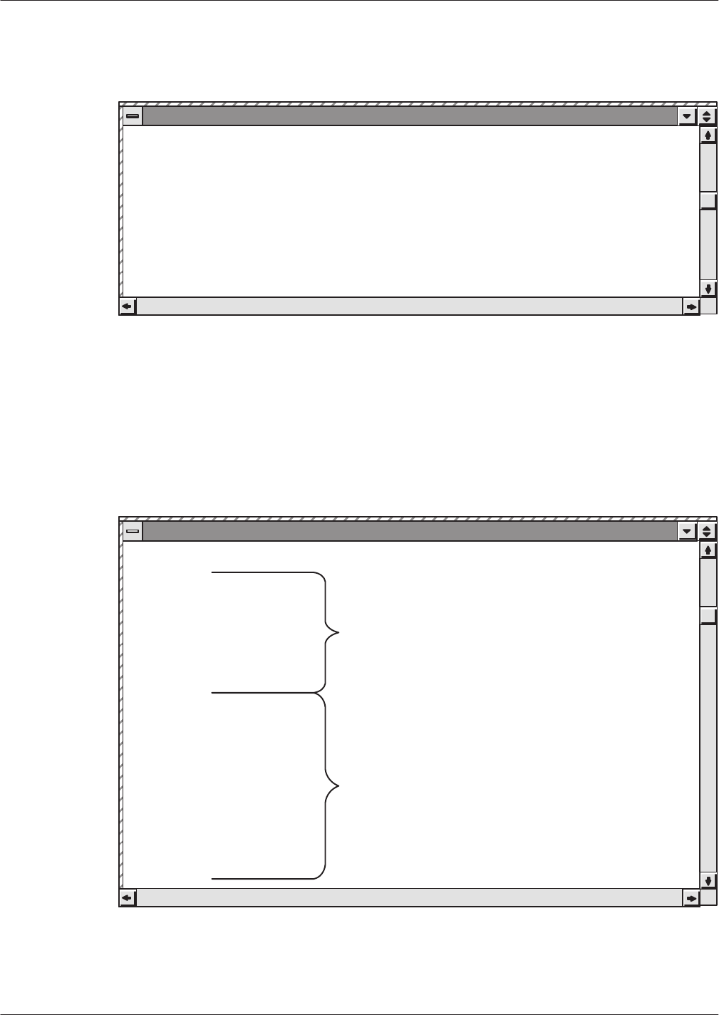
11B-4
Installation and Maintenance
V
olume
Octel Overture 200/300 Serenade 3.0
PB60014–01
Following
is an example of CONFIG system information for the current cabinet, with system name
[ works9 ]:
Mon Jun 6 18:32:29 1994 [ works9 ] : Quick Dump: VMX–DIAL.config
systemName=OCTEL
sysSerialNum=123456
systemID=98765
LOCTABLE
This
part of the private MIB contains the Digital Network T
raf
fic Report and data from the LOCA
TION
T
able. It shows traf
fic information such as connections and messages to each other digital location from
the current cabinet. It also shows some configuration information for each digital location, including
name, IP address, connection type, etc.
Following is an example of LOCT
ABLE:
Mon Jun 6 18:33:42 1994 [ works9 ] : Quick Dump: VMX–DIAL.locTable
KEY=1
locIndex=1
locName=ATLNT2
locIpAddr=157.156.16.10
locLinkType=lowspeed
locInDomain=no
locColocated=yes
route1=TO2
route2=
route3=
cattempts=16
cfailures=0
cdroppeds=0
cbusys=0
cdayMin=1
cnightMin=0
mdAttempts=16
mdFails=0
mdRetries=0
mdDiskfulls=0
mdMbxfails=0
mdMinute=12
locPlayedNames=0
locLinkdrops=16
LOCATION Table
Digital Network Traffic Report
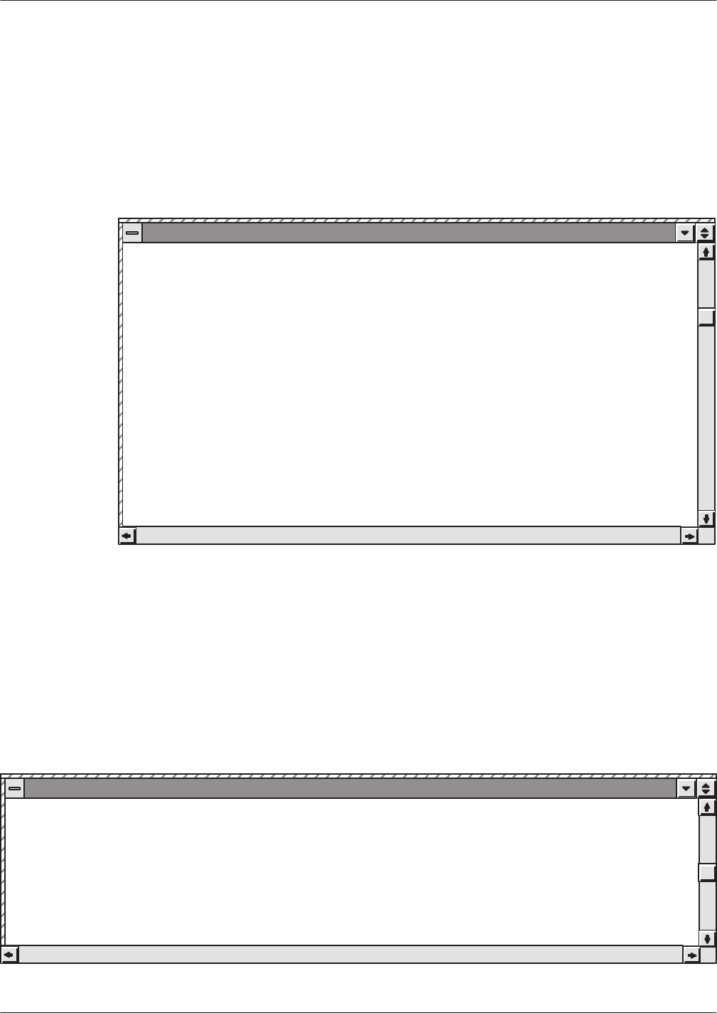
SNMP
1
1B-5
Octel Overture 200/300 Serenade 3.0
PB60014–01
DNETSTAT
This
part of the private MIB contains the Digital Network Performance Report. It shows a high-level
summary of all digital networking activity
, such as messages sent/received, LAN channel usage, and
connections.
Following is an example of DNETST
AT:
Mon Jun 6 18:32:47 1994 [ works9 ] : Quick Dump: VMX–DIAL.dNetstat
sentMsgs=0
recvMsgs=0
recvNames=0
playedRtNames=0
secSent=0
secRecv=0
lchNumber=4
sec50pct=0
sec75pct=0
sec100pct=0
lchInSendSec=0
lchInRecvSec=0
outAttempts=0
outRejects=0
outGotBusys=0
inAttempts=0
inRejects=0
inGotBusys=0
lanAvailPct=100
HWERRTABLE
This
part of the private MIB is a listing of the system Hardware Error T
able. It shows the error type,
when it occurred, and some additional error
-specific data fields. The Hardware Error T
able output is not
filtered to exclude errors not relating to Digital Networking. All hardware errors are reported.
Following is an example of HWERR
TABLE:
Mon Jun 6 18:33:21 1994 [ works9 ] : Quick Dump: VMX–DIAL.hwerrTable
KEY heIndex heErType heSlot heMon heDay heHour heMin heChnum hePrio heCnt heData1 heData2 heData3 heData4
1 1 64 6 jun 6 16 41 00000000 3 1 00000002 00000002 00000000 00000000
2 2 64 6 jun 6 16 42 00000000 3 1 00000009 00000004 00000004 00000004
3 3 24 4 jun 6 16 53 00000001 2 99 00000005 00000001 00000004 00000003

11B-6
Installation and Maintenance
V
olume
Octel Overture 200/300 Serenade 3.0
PB60014–01
SNMP Query Tracing
When
an SNMP query is received by an
Octel Overture 200/300, the event is logged in the CP trace.
Each type of query has an identifying number that appears in the AUX field of the CP trace.
Identifying
Number
CPT T
race Logged To
001 Digital
Network Performance Report or System Configuration
002
Digital Network T
raf
fic Report
003
Hardware Error T
able
Following is an example of a CP trace:
@LOG PR CPT
Specify Print Option(s):
”S”tart<time>,’E”nd<time>,”L”ine<length>,”P”age<length>”\”
”C”ontinuous
Filters: PR TY EV AU MB MS SL UN LI SO D1 D2 D3 D4 D5
>s94 09 08 14 45 ev snmp
MM/DD/YY HH:MM:SS PRT TYPE EVENT AUX MBX/EXTN MSG# SL U L SOURCE
D1 D2 D3 D4 D5
09/08/94 14:45:37 LAN_IN SNMP_QRY 001
09/08/94 14:45:37 LAN_OUT SNMP_SND 001
09/08/94 14:45:43 LAN_IN SNMP_QRY 002
09/08/94 14:45:43 LAN_OUT SNMP_SND 002
09/08/94 14:45:48 LAN_IN SNMP_QRY 002
09/08/94 14:45:48 LAN_OUT SNMP_SND 002
09/08/94 14:46:28 LAN_IN SNMP_QRY 002
09/08/94 14:46:28 LAN_OUT SNMP_SND 002
09/08/94 14:47:59 LAN_IN SNMP_QRY 003
09/08/94 14:47:59 LAN_OUT SNMP_SND 003
09/08/94 14:48:04 LAN_IN SNMP_QRY 003
09/08/94 14:48:04 LAN_OUT SNMP_SND 003
09/08/94 14:48:10 LAN_IN SNMP_QRY 003
09/08/94 14:48:10 LAN_OUT SNMP_SND 003
09/08/94 14:48:15 LAN_IN SNMP_QRY 003
09/08/94 14:48:15 LAN_OUT SNMP_SND 003
Type
1 queries produce a single CPT entry
. T
ype 2 queries produce one entry per network location
configured with. T
ype 3 queries produce one entry more than the number of error entries.
SNMP Private MIB Information Refresh
In
the Octel Overture 200/300, the LAN card maintains a local copy of private MIB information. The
LAN card updates this copy with new information from the CPU at intervals of 2 minutes
When the SNMP manager queries the LAN card for private MIB information, the LAN card responds
immediately from its local copy. The MIB information sent may not reflect changes that have occurred in
the last two minutes, until the LAN card refreshes its copy from the CPU.

SNMP
1
1B-7
Octel Overture 200/300 Serenade 3.0
PB60014–01
11B.4 USING SNMP TRAPS
SNMP
traps are SNMP protocol messages initiated by the managed system to report a predefined error
condition. For the Octel Overture 200/300, these errors are hardware errors as logged in the Hardware
Error T
able. In addition to the name and ID of the logging system, all information for the hardware error
that caused the trap is listed.
Hardware errors have four priorities, ranging from priority 0 (lowest) to priority 3 (highest). An alarm
notification trap is made depending on the combination of the error priority and the number of times the
error (the same type with the same data) is logged. An alarm notification trap is made for the following
combinations of priority and number of times the error is logged:
Error
Priority
Number of T
imes
Error Logged
3 1
225
150
No
alarm notification is made for priority 0, which reports the test of the alarm (command
TE A).
Conditions for SNMP Trap Notification
The
CPU generates an SNMP trap request to the LAN card under the following conditions:
The SNMP manager system is configured, which means
–
System Parameter 235 — LAN: SNMP MANAGER IP ADDRESS, is configured.
or
–
Both System Parameter 233 — LAN: NAME SERVER IP ADDRESS, and System
Parameter 236 — LAN: SNMP MANAGER HOST ASCII NAME, are configured.
System Parameter 242 — LAN: SEND TRAP T
O THE SNMP MANAGER ON ALARM, is set to
YES.
A hardware error is logged a suf
ficient number of times for its priority to cause a system alarm
notification.
An alarm outcall is repeated until acknowledgment. There is no such acknowledgment from the
SNMP manager system for SNMP traps. SNMP notification is done only once per occurrence.
Configuring SNMP
The
following information must be configured through system parameters:
The SNMP manager
’
s IP address. System Parameter 235 — SNMP MANAGER IP ADDRESS
Sometimes SNMP managers may only have an ASCII name configured, and the actual mapping from the
ASCII name to an IP address is performed by a name server
. In this case, the following system
parameters must be configured:

11B-8
Installation and Maintenance
V
olume
Octel Overture 200/300 Serenade 3.0
PB60014–01
The
IP address of the name server
. System Parameter 233 — LAN: NAME SER
VER IP ADDRESS
The ASCII name of the SNMP manager
. System Parameter 236 — LAN: SNMP MANAGER HOST
ASCII NAME
When the same hardware error is logged a suf
ficient number of times (the number is predefined), an
alarm outcall is made. T
o notify the SNMP manager of the first occurrence of this alarm outcall, the
following system parameter must be enabled:
System Parameter 242 — LAN: SEND TRAP T
O THE SNMP MANAGER ON ALARM
The default setting for System Parameter 242 is
NO
. If the SNMP manager system is not configured,
System Parameter 242 cannot be set to
YES
, and the following message is given:
Please configure system parameter 235, or 236 and 233, for the SNMP
manager system first.
For
purposes of authentication and providing access privileges, the SNMP manager and agents exchange
SNMP READ COMMUNITY and SNMP READ WRITE COMMUNITY names. As the names suggest,
members of a READ COMMUNITY can only “read” the SNMP variables. Members of a READ WRITE
COMMUNITY can not only “read” the SNMP variables through SNMP queries but also modify those
SNMP variables that are modifiable. The following system parameters are used to specify the READ and
READ WRITE communities:
System Parameter 239 — LAN: SNMP READ COMMUNITY
System Parameter 240 — LAN: SNMP READ WRITE COMMUNITY
The character strings in System Parameter 239 and System Parameter 240 are transmitted between the
Octel Overture 200/300 and the SNMP manager application to verify each other
’
s access to the data
being requested in a query
. If the character strings do not match, the queries will fail.
In the SYSTEM P
ARAMETER T
able in UPDA
TE, even if a string is entered in mixed upper
- and
lowercase, it is stored in the system as uppercase. However
, when the string is transmitted to the LAN
card, it is then converted to all lowercase. It is this lowercase string that must match the community read
and write strings, as configured in the SNMP manager
.
The following examples show this conversion process.
.M SYS 239
Enter the SNMP Read Community Name.
(1 – 19 characters, empty line = PA_LAB_READ)
MOD:PA_Lab_Read
Enter system parameter index.
MOD:240
Enter the SNMP Read Write Community Name.
(1 – 19 characters, empty line = PA_LAB_WRITE)
MOD:PA_Lab_Write
Enter system parameter index.
MOD:
.L SYS 239–240
INDEX VALUE (LST?MOD) PARAMETER NAME:
239 PA_LAB_READ L/M LAN: SNMP READ COMMUNITY
240 PA_LAB_WRITE L/M LAN: SNMP READ WRITE COMMUNITY

SNMP
1
1B-9
Octel Overture 200/300 Serenade 3.0
PB60014–01
@CON 6
Connecting to LAN in slot 6
LAN (Ethernet) Link: 08/1/1994 12:39:04 (018664b6:018665b6) Rev. 1.1.2
Current Time: 09/12/1994 17:20:42 @ Slot 6
LAN<l cfg
Installation Name : V200_1
VMX System ID : 200111
Host Name : v200_1
Domain Name :
Internet Address : 148.147.250.114
Subnet Mask : 255.255.255.0
Ethernet Address :00–c0–94–00–00–0e
GateWay Address : 0.0.0.0
Name Server Addr :0.0.0.0
SNMP – Manager : 148.147.250.28
Manager Name : sunnet
Sys Name : v200_1
Location :
Contact :
RdCommunity : pa_lab_read
RdWRCommunity : pa_lab_write
Example of an SNMP T
rap Report
Following
is an example of an SNMP trap report generated on a system error alarm:
Mon Jun 6 17:40:33 1994 [ works9 ] : Trap:
sequence=55
receive–time=Mon Jun 6 17:40:33 1994
version=0
community=public
enterprise=octel.octelOIDs.octelPlatforms.vmx200.8.1.0
source–time=00:00:50.80
trap–type=enterprise specific trap: 1
sysDescr=OCTEL – VMX200 Voice Mail System, Id: 98765 Rev 8.1.
KEY=65535
heErType=64
heSlot=6
heMon=jun
heDay=6
heHour=16
heMin=42
heChnum=0
hePrio=3
heCnt=1
heData1=00000009
heData2=00000004
heData3=00000004
heData4=00000004
Save...
65 165

11B-10
Installation and Maintenance
V
olume
Octel Overture 200/300 Serenade 3.0
PB60014–01
SNMP Trap CP T
race Example
Following
is an example of a CP trace for an SNMP trap:
MM/DD/YY HH:MM:SS PRT TYPE EVENT AUX MBX/EXTN MSG# SL U L SOURCE
D1 D2 D3 D4 D5
05/18/94 12:06:08 LAN_OUT SNMP_TRAP 001
The
value 001 (currently the only one defined) in the auxiliary field (AUX) indicates that the SNMP trap
is being sent because of a hardware error
.
Hardware Error Table Entries for an SNMP Trap
A
hardware error type 42, DA
T
A1 = 17(hex) will be logged if a trap needs to be sent but the SNMP
system manager is not known. For example,
@L H
THU 05/19 09:13:17 1994 ABC,INC ID:123456 S/N:123456 PBX:23
CLEARED: 05/19 09:10
TYPE SLOT CHNL PRIO DATE TIME #BAD DATA1 DATA2 DATA3 DATA4
42 06 00 1 05/19 09:13 1 00000017 00000000 00000000 00000000
For
the SNMP manager system to be configured, either its IP address (System Parameter 235) or its host
name (System Parameter 236)
and
the IP address of the domain name server (System Parameter 233)
must be known.
Once an SNMP trap has been generated, the
L H
command displays this information. For example,
@L H
THU 05/19 13:22:08 1994 ASKME ID:123456 S/N:123456 PBX:23
CLEARED: 05/19 12:51
*** SNMP MANAGER SYSTEM HAS BEEN NOTIFIED ***
TYPE SLOT CHNL PRIO DATE TIME #BAD DATA1 DATA2 DATA3 DATA4
33 01 00 3 05/19 12:54 1 00000000 00000003 00000002 00000000
64 06 00 3 05/19 13:01 1 00000002 00000001 00000000 00000000
After
successful completion of an
SNMP TEST,
hardware error type 64, DA
T
A1 = 0E(hex) with a
priority of 0 is logged.

SNMP
1
1B-11
Octel Overture 200/300 Serenade 3.0
PB60014–01
Testing SNMP Trap Functionality
An
Octel Overture 200/300 can inform an SNMP manager system when a qualified hardware error is
logged. The
TEST SNMP
command tests the mechanism and gives assurance that the Octel Overture
200/300 can communicate to the SNMP manager system, is provided.
Before a
TEST SNMP
command can be used, System Parameter 242 must be set to
YES
, and the SNMP
manager system must be configured, which means that either System Parameter 235 or System
Parameters 233 and 236 must be configured.
TEST SNMP Operation
At
the @ prompt, enter
TEST SNMP
The Octel Overture 200/300 then generates hardware error type 64, DA
T
A1 = 0E, with a priority of 0.
The system sends a trap on this error to the SNMP manager system. The user will be informed that the
alarm has been sent and the test is completed.
The user may then have the SNMP manager system pull up the private MIBs for hardware errors on the
Octel Overture 200/300. Successful completion of the test, however
, does not guarantee that the SNMP
manager system did indeed receive the trap. The SNMP protocol does not provide for an
acknowledgment from the manager system. It is recommended that the SNMP manager system be pinged
before doing
TEST SNMP.
When
TEST SNMP
is complete, the Hardware Error T
able should be listed. The listing will include the
type 64 error and the following message:
*** SNMP MANAGER SYSTEM HAS BEEN NOTIFIED ***
The
C H
command should be used to clear both of these conditions.
TEST SNMP Messages
On
successful completion of the
TEST SNMP
command, the following message is displayed:
ALARM HAS BEEN SENT TO THE SNMP MANAGER SYSTEM.
If
for any reason the SNMP trap could not be sent, one of the following messages is displayed, as
appropriate:
PLEASE CONFIGURE SYSTEM PARAMETERS 235 OR 236 AND 233.
LAN COMMUNICATION IS NOT UP.
SYSTEM DOES NOT HAVE DIGITAL NETWORKING FEATURE.
SYSTEM PARAMETER FOR DIGITAL NETWORKING IS NOT ENABLED.
SYSTEM PARAMETER FOR SNMP TRAPS IS NOT ENABLED.
HARDWARE ERROR TABLE IS FULL. PLEASE CLEAR IT FIRST.
USER ABORT ...
SYSTEM ERROR. PLEASE CONTACT TECHNICAL SUPPORT.
FAILED TO SEND SNMP TRAP.

11B-12
Installation and Maintenance
V
olume
Octel Overture 200/300 Serenade 3.0
PB60014–01
TEST SNMP Examples
Following
is an example of a successful
TEST SNMP:
@TEST SNMP
ALARM HAS BEEN SENT TO THE SNMP MANAGER SYSTEM.
Following
is an example of an unsuccessful
TEST SNMP:
@TEST SNMP
LAN COMMUNICATION IS NOT UP.

Octel
Private MIB 1
1C-1
Octel Overture 200/300 Serenade 3.0
PB60014–01
APPENDIX
C
PRIV
A
TE MIB
This
appendix provides a sample Internet session for obtaining the
Private MIB from Internet and a
listing of the
Private MIB.
T
o obtain the private MIB file, connect to the Internet and then do FTP ANONYMOUS from ftp.ISI.EDU
(128.9.176.20). Following is a sample session:
prompt>
prompt>ftp.isi.edu
Name (148.147.1.12:username):anonymous
331 Guest login ok, send your complete e–mail address as password.
Password:<type in your e–mail address here>
230 Guest login ok, access restrictions apply.
ftp>cd mib
ftp>get octel–vmxdial.mib
200 PORT command successful.
150 Opening ASCII mode data connection for octel–vmxdial.mib (210278 bytes).
226 Transfer complete.
local:octel–vmxdial.mib remote:octel–mvxdial.mib
216459 bytes received in 54 seconds (3.9 Kbytes/s)
ftp>quit
222 Goodbye.
prompt>
Bold
entries are what you type. Entries enclosed in < > indicate that you should substitue with the
right data.

11C-2
Installation and Maintenance
V
olume
Octel Overture 200/300 Serenade 3.0
PB60014–01
VMX–DIAL
DEFINITIONS ::= BEGIN
––
–– VMX–DIAL private MIB definitions for the VMX200/300
–– Filename: vmxdial.mib
–– This MIB definition is provided for use with OCtel’s VMX200/300
–– product only.
––
–– Contact Person:
–– LAN Engineering Group
–– Octel Communication Corporation
––
–– NOTE:
–– 1. This file will be published electronically in
–– venera.isi.edu and can be obtained using ftp anonymous.
––
–– 2. Sunnet Manager User:
–– Sunnet doesn’t support multi–dimensional table. To make this file works
–– with subnet, the mnemonic for the second level table need to be replaced
–– by the number it represents. Example:
–– locEntry is a table entry, and
–– route1 is defined as locroute.1 where locroute is locEntry.7
–– the above definition need to be changed as follows:
–– . remove the definition for locroute
–– . route1 is defined as locEntry.7.1
–– This need to be done for all multi–dimensional tables.
––
IMPORTS
enterprises, NetworkAddress, IpAddress, Counter, Gauge,
TimeTicks
FROM RFC1155–SMI
OBJECT–TYPE
FROM RFC–1212
DisplayString
FROM RFC1213–MIB;
octel
OBJECT IDENTIFIER ::= { enterprises 662 }
octelOIDs
OBJECT IDENTIFIER ::= { octel 1 }
octelPlatforms
OBJECT IDENTIFIER ::= { octelOIDs 1}
vmx200
OBJECT IDENTIFIER ::= { octelPlatforms 3 }
vmx300
OBJECT IDENTIFIER ::= { octelPlatforms 4 }
octelProducts
OBJECT IDENTIFIER ::= { octel 3 }
vmxDial
OBJECT IDENTIFIER ::= { octelProducts 1 }
config
OBJECT IDENTIFIER ::= { vmxDial 1 }
dNetstat
OBJECT IDENTIFIER ::= { vmxDial 2 }
location
OBJECT IDENTIFIER ::= { vmxDial 3 }
hwerr
OBJECT IDENTIFIER ::= { vmxDial 4 }
–– dNetstat subtrees
message
OBJECT IDENTIFIER ::= { dNetstat 1 }
lanCh
OBJECT IDENTIFIER ::= { dNetstat 2 }
lanConn
OBJECT IDENTIFIER ::= { dNetstat 3 }
systemName OBJECT–TYPE
SYNTAX DisplayString (SIZE (0..255))
ACCESS read–only
STATUS mandatory
DESCRIPTION
”VMX System Name, from Configuration”
::= { config 1 }
sysSerialNum OBJECT–TYPE

Octel
Private MIB 1
1C-3
Octel Overture 200/300 Serenade 3.0
PB60014–01
SYNTAX DisplayString (SIZE (0..255))
ACCESS read–only
STATUS mandatory
DESCRIPTION
”VMX System Serial Number.”
::= { config 2 }
systemID OBJECT–TYPE
SYNTAX DisplayString (SIZE (0..255))
ACCESS read–only
STATUS mandatory
DESCRIPTION
”VMX System Identification Number.”
::= { config 3 }
sentVoiceMsgs OBJECT–TYPE
SYNTAX Counter
ACCESS read–only
STATUS mandatory
DESCRIPTION
”Total number of voice messages sent to the networks”
::= { message 1 }
recvVoiceMsgs OBJECT–TYPE
SYNTAX Counter
ACCESS read–only
STATUS mandatory
DESCRIPTION
”Total number of voice messages received from the networks”
::= { message 2 }
sentFaxMsgs OBJECT–TYPE
SYNTAX Counter
ACCESS read–only
STATUS mandatory
DESCRIPTION
”Total number of fax messages sent to the networks”
::= { message 3 }
recvFaxMsgs OBJECT–TYPE
SYNTAX Counter
ACCESS read–only
STATUS mandatory
DESCRIPTION
”Total number of fax messages received from the networks”
::= { message 4 }
recvNames OBJECT–TYPE
SYNTAX Counter
ACCESS read–only
STATUS mandatory
DESCRIPTION
”Total number of name received from the networks”
::= { message 5 }
playedRtNames OBJECT–TYPE
SYNTAX Counter
ACCESS read–only
STATUS mandatory
DESCRIPTION
”Total number of Real Time network name played”
::= { message 6 }
secSent OBJECT–TYPE
SYNTAX INTEGER
ACCESS read–only
STATUS mandatory
DESCRIPTION

11C-4
Installation and Maintenance
V
olume
Octel Overture 200/300 Serenade 3.0
PB60014–01
”Total number of seconds of message sent to the networks”
::= { message 7 }
secRecv OBJECT–TYPE
SYNTAX INTEGER
ACCESS read–only
STATUS mandatory
DESCRIPTION
”Total number of seconds of message received from the networks”
::= { message 8 }
lchNumber OBJECT–TYPE
SYNTAX INTEGER
ACCESS read–only
STATUS mandatory
DESCRIPTION
”Maximum number of LAN channel available in the system.”
::= { lanCh 1 }
sec50pct OBJECT–TYPE
SYNTAX INTEGER
ACCESS read–only
STATUS mandatory
DESCRIPTION
”Total number of second that 50 percent of lan channel is busy”
::= { lanCh 2 }
sec75pct OBJECT–TYPE
SYNTAX INTEGER
ACCESS read–only
STATUS mandatory
DESCRIPTION
”Total number of second that 75 percent of lan channel is busy”
::= { lanCh 3 }
sec100pct OBJECT–TYPE
SYNTAX INTEGER
ACCESS read–only
STATUS mandatory
DESCRIPTION
”Total number of second that all of lan channel is busy”
::= { lanCh 4 }
lchInSendSec OBJECT–TYPE
SYNTAX INTEGER
ACCESS read–only
STATUS mandatory
DESCRIPTION
”Number of second LCH is in used for sending message”
::= { lanCh 5 }
lchInRecvSec OBJECT–TYPE
SYNTAX INTEGER
ACCESS read–only
STATUS mandatory
DESCRIPTION
”Number of second LCH is in used for receiving message”
::= { lanCh 6 }
outAttempts OBJECT–TYPE
SYNTAX Counter
ACCESS read–only
STATUS mandatory
DESCRIPTION
”Number of time an outgoing lan connection is attempted”
::= { lanConn 1 }
outRejects OBJECT–TYPE
SYNTAX Counter

Octel
Private MIB 1
1C-5
Octel Overture 200/300 Serenade 3.0
PB60014–01
ACCESS read–only
STATUS mandatory
DESCRIPTION
”Number of time an outgoing lan connection is rejected”
::= { lanConn 2 }
outGotBusys OBJECT–TYPE
SYNTAX Counter
ACCESS read–only
STATUS mandatory
DESCRIPTION
”Number of time an outgoing lan connection is rejected,
due to all LCH busy”
::= { lanConn 3 }
inAttempts OBJECT–TYPE
SYNTAX Counter
ACCESS read–only
STATUS mandatory
DESCRIPTION
”Number of time an incoming lan connection is requested”
::= { lanConn 4 }
inRejects OBJECT–TYPE
SYNTAX Counter
ACCESS read–only
STATUS mandatory
DESCRIPTION
”Number of time an incoming lan connection is rejected”
::= { lanConn 5 }
inGotBusys OBJECT–TYPE
SYNTAX Counter
ACCESS read–only
STATUS mandatory
DESCRIPTION
”Number of time an incoming lan connection is rejected,
due to all LCH busy”
::= { lanConn 6 }
lanAvailPct OBJECT–TYPE
SYNTAX INTEGER
ACCESS read–only
STATUS mandatory
DESCRIPTION
”Percentage of LAN availability.”
::= { dNetstat 4 }
locTable OBJECT–TYPE
SYNTAX SEQUENCE OF LocEntry
ACCESS not–accessible
STATUS mandatory
DESCRIPTION
”List of active Digital Network Location.”
::= { location 1 }
locEntry OBJECT–TYPE
SYNTAX LocEntry
ACCESS not–accessible
STATUS mandatory
DESCRIPTION
”Each entry contains info about the Network Location.”
INDEX { locIndex }
::= { locTable 1 }
LocEntry ::= SEQUENCE {
locIndex

11C-6
Installation and Maintenance
V
olume
Octel Overture 200/300 Serenade 3.0
PB60014–01
INTEGER,
locName
DisplayString (SIZE (0..255)),
locIpAddr
IpAddress,
locLinkType
DisplayString,
locInDomain
DisplayString,
locColocated
DisplayString,
route1
DisplayString (SIZE (0..255)),
route2
DisplayString (SIZE (0..255)),
route3
DisplayString (SIZE (0..255)),
cattempts
Counter,
cfailures
Counter,
cdroppeds
Counter,
cbusys
Counter,
cdayMin
INTEGER,
cnightMin
INTEGER,
mdvcAttempts
Counter,
mdvcFails
Counter,
mdvcRetries
Counter,
mdfxAttempts
Counter,
mdfxFails
Counter,
mdfxRetries
Counter,
mdDiskfulls
Counter,
mdMbxfails
Counter,
mdMinute
INTEGER,
locPlayedNames
Counter,
locLinkdrops
Counter,
locAnalogstndbys
Counter
}
locIndex OBJECT–TYPE
SYNTAX INTEGER
ACCESS read–only
STATUS mandatory
DESCRIPTION
”Index of this Location Entry”

Octel
Private MIB 1
1C-7
Octel Overture 200/300 Serenade 3.0
PB60014–01
::= { locEntry 1 }
locName OBJECT–TYPE
SYNTAX DisplayString (SIZE (0..255))
ACCESS read–only
STATUS mandatory
DESCRIPTION
”System Name of This Location Entry, SELF means this system”
::= { locEntry 2 }
locIpAddr OBJECT–TYPE
SYNTAX IpAddress
ACCESS read–only
STATUS mandatory
DESCRIPTION
”Internet Address of this Location”
::= { locEntry 3 }
locLinkType OBJECT–TYPE
SYNTAX INTEGER {
lowspeed(1),
highspeed(2)
}
ACCESS read–only
STATUS mandatory
DESCRIPTION
”Type of the network interface”
::= { locEntry 4 }
locInDomain OBJECT–TYPE
SYNTAX INTEGER {
no(1),
yes(2)
}
ACCESS read–only
STATUS mandatory
DESCRIPTION
”Whether this location is in the same Uniform Numbering Plan
domain. ”
::= { locEntry 5 }
locColocated OBJECT–TYPE
SYNTAX INTEGER {
no(1),
yes(2)
}
ACCESS read–only
STATUS mandatory
DESCRIPTION
”Whether this location is in the same location.”
::= { locEntry 6 }
locroute OBJECT IDENTIFIER ::= { locEntry 7 }
route1 OBJECT–TYPE
SYNTAX DisplayString (SIZE (0..255))
ACCESS read–only
STATUS mandatory
DESCRIPTION
”First Entry in the Route Table for this location.”
::= { locroute 1 }
route2 OBJECT–TYPE
SYNTAX DisplayString (SIZE (0..255))
ACCESS read–only
STATUS mandatory
DESCRIPTION
”Second Entry in the Route Table for this location.”

11C-8
Installation and Maintenance
V
olume
Octel Overture 200/300 Serenade 3.0
PB60014–01
::= { locroute 2 }
route3 OBJECT–TYPE
SYNTAX DisplayString (SIZE (0..255))
ACCESS read–only
STATUS mandatory
DESCRIPTION
”Third Entry in the Route Table for this location.”
::= { locroute 3 }
locConn OBJECT IDENTIFIER ::= { locEntry 8 }
cattempts OBJECT–TYPE
SYNTAX Counter
ACCESS read–only
STATUS mandatory
DESCRIPTION
”Number of times LAN connection attempted.”
::= { locConn 1 }
cfailures OBJECT–TYPE
SYNTAX Counter
ACCESS read–only
STATUS mandatory
DESCRIPTION
”Number of times LAN connection to this location failed.”
::= { locConn 2 }
cdroppeds OBJECT–TYPE
SYNTAX Counter
ACCESS read–only
STATUS mandatory
DESCRIPTION
”Number of times LAN connection to this location dropped.”
::= { locConn 3 }
cbusys OBJECT–TYPE
SYNTAX Counter
ACCESS read–only
STATUS mandatory
DESCRIPTION
”Number of times All LAN Connection is busy.”
::= { locConn 4 }
cdayMin OBJECT–TYPE
SYNTAX INTEGER
ACCESS read–only
STATUS mandatory
DESCRIPTION
”Number of minutes(day time) LAN connection is established.”
::= { locConn 5 }
cnightMin OBJECT–TYPE
SYNTAX INTEGER
ACCESS read–only
STATUS mandatory
DESCRIPTION
”Number of minutes(night time) LAN connection is established.”
::= { locConn 6 }
msgDelivery OBJECT IDENTIFIER ::= { locEntry 9 }
mdvcAttempts OBJECT–TYPE
SYNTAX Counter
ACCESS read–only
STATUS mandatory
DESCRIPTION
”Number of voice message delivery attempts to this location.”
::= { msgDelivery 1 }
mdvcFails OBJECT–TYPE

Octel
Private MIB 1
1C-9
Octel Overture 200/300 Serenade 3.0
PB60014–01
SYNTAX Counter
ACCESS read–only
STATUS mandatory
DESCRIPTION
”Number of voice message delivery failures to this location.”
::= { msgDelivery 2 }
mdvcRetries OBJECT–TYPE
SYNTAX Counter
ACCESS read–only
STATUS mandatory
DESCRIPTION
”Number of voice message delivery retries to this location.”
::= { msgDelivery 3 }
mdfxAttempts OBJECT–TYPE
SYNTAX Counter
ACCESS read–only
STATUS mandatory
DESCRIPTION
”Number of fax message delivery attempts to this location.”
::= { msgDelivery 4 }
mdfxFails OBJECT–TYPE
SYNTAX Counter
ACCESS read–only
STATUS mandatory
DESCRIPTION
”Number of fax message delivery failures to this location.”
::= { msgDelivery 5 }
mdfxRetries OBJECT–TYPE
SYNTAX Counter
ACCESS read–only
STATUS mandatory
DESCRIPTION
”Number of fax message delivery retries to this location.”
::= { msgDelivery 6 }
mdDiskfulls OBJECT–TYPE
SYNTAX Counter
ACCESS read–only
STATUS mandatory
DESCRIPTION
”Number of message delivery to this location fails due to
disk full.”
::= { msgDelivery 7 }
mdMbxfails OBJECT–TYPE
SYNTAX Counter
ACCESS read–only
STATUS mandatory
DESCRIPTION
”Number of message delivery to this location fails due to
mailbox verification failure.”
::= { msgDelivery 8 }
mdMinute OBJECT–TYPE
SYNTAX INTEGER
ACCESS read–only
STATUS mandatory
DESCRIPTION
”Total number of message (in minute) delivered to
this location.”
::= { msgDelivery 9 }
locPlayedNames OBJECT–TYPE

11C-10
Installation and Maintenance
V
olume
Octel Overture 200/300 Serenade 3.0
PB60014–01
SYNTAX Counter
ACCESS read–only
STATUS mandatory
DESCRIPTION
”Number of Real Time Network Name Played from this location.”
::= { locEntry 10 }
locLinkdrops OBJECT–TYPE
SYNTAX Counter
ACCESS read–only
STATUS mandatory
DESCRIPTION
”Number of time LAN connection dropped, High Speed link only.”
::= { locEntry 11 }
locAnalogstndbys OBJECT–TYPE
SYNTAX Counter
ACCESS read–only
STATUS mandatory
DESCRIPTION
”Number of times Analog Standby used to this location.”
::= { locEntry 12 }
hwerrTable OBJECT–TYPE
SYNTAX SEQUENCE OF HwerrEntry
ACCESS not–accessible
STATUS mandatory
DESCRIPTION
”Table of Hardware errors.”
::= { hwerr 1 }
hwerrEntry OBJECT–TYPE
SYNTAX HwerrEntry
ACCESS not–accessible
STATUS mandatory
DESCRIPTION
”Hardware Error table Entry”
INDEX { heIdx }
::= { hwerrTable 1 }
HwerrEntry ::= SEQUENCE {
heIdx
INTEGER,
heType
INTEGER,
heSlot
INTEGER,
heMon
INTEGER,
heDay
INTEGER,
heHour
INTEGER,
heMin
INTEGER,
heCh
INTEGER,
hePrio
INTEGER,
heCnt
INTEGER,
heData1
OCTET STRING,
heData2
OCTET STRING,

Octel
Private MIB 1
1C-11
Octel Overture 200/300 Serenade 3.0
PB60014–01
heData3
OCTET STRING,
heData4
OCTET STRING
}
heIdx OBJECT–TYPE
SYNTAX INTEGER
ACCESS read–only
STATUS mandatory
DESCRIPTION
”Index of this Hardware Entry”
::= { hwerrEntry 1 }
heType OBJECT–TYPE
SYNTAX INTEGER
ACCESS read–only
STATUS mandatory
DESCRIPTION
”Error Type of this hardare error.”
::= { hwerrEntry 2 }
heSlot OBJECT–TYPE
SYNTAX INTEGER
ACCESS read–only
STATUS mandatory
DESCRIPTION
”Slot Number of this Hardware Error Entry”
::= { hwerrEntry 3 }
heMon OBJECT–TYPE
SYNTAX INTEGER {
jan(1),
feb(2),
mar(3),
apr(4),
may(5),
jun(6),
jul(7),
aug(8),
sep(9),
oct(10),
nov(11),
dec(12)
}
ACCESS read–only
STATUS mandatory
DESCRIPTION
”Month in which this Hardware Error Entry occurred”
::= { hwerrEntry 4 }
heDay OBJECT–TYPE
SYNTAX INTEGER
ACCESS read–only
STATUS mandatory
DESCRIPTION
”Day on which this Hardware Error Entry occurred”
::= { hwerrEntry 5 }
heHour OBJECT–TYPE
SYNTAX INTEGER
ACCESS read–only
STATUS mandatory
DESCRIPTION
”Hour on which this Hardware Error Entry occurred”
::= { hwerrEntry 6 }

11C-12
Installation and Maintenance
V
olume
Octel Overture 200/300 Serenade 3.0
PB60014–01
heMin
OBJECT–TYPE
SYNTAX INTEGER
ACCESS read–only
STATUS mandatory
DESCRIPTION
”Minute on which this Hardware Error Entry occurred”
::= { hwerrEntry 7 }
heCh OBJECT–TYPE
SYNTAX OCTET STRING
ACCESS read–only
STATUS mandatory
DESCRIPTION
”Channel Number of this Hardware Error Entry”
::= { hwerrEntry 8 }
hePrio OBJECT–TYPE
SYNTAX INTEGER
ACCESS read–only
STATUS mandatory
DESCRIPTION
”Priority of this Hardware Error Entry”
::= { hwerrEntry 9 }
heCnt OBJECT–TYPE
SYNTAX INTEGER
ACCESS read–only
STATUS mandatory
DESCRIPTION
”Frequency of this hardare error.”
::= { hwerrEntry 10 }
heData1 OBJECT–TYPE
SYNTAX OCTET STRING
ACCESS read–only
STATUS mandatory
DESCRIPTION
”Data1 of this hardare error.”
::= { hwerrEntry 11 }
heData2 OBJECT–TYPE
SYNTAX OCTET STRING
ACCESS read–only
STATUS mandatory
DESCRIPTION
”Data2 of this hardare error.”
::= { hwerrEntry 12 }
heData3 OBJECT–TYPE
SYNTAX OCTET STRING
ACCESS read–only
STATUS mandatory
DESCRIPTION
”Data3 of this hardare error.”
::= { hwerrEntry 13 }
heData4 OBJECT–TYPE
SYNTAX OCTET STRING
ACCESS read–only
STATUS mandatory
DESCRIPTION
”Data4 of this hardare error.”
::= { hwerrEntry 14 }
hwerrTrap TRAP–TYPE
ENTERPRISE octel
VARIABLES { sysDescr, heType, heSlot, heMon, heDay,
heHour, heMin, heCh, hePrio, heCnt,

Octel
Private MIB 1
1C-13
Octel Overture 200/300 Serenade 3.0
PB60014–01
heData1, heData2, heData3, heData4 }
DESCRIPTION
”A hwerrTrap signifies that the VMX system has hardware errors
logged. This trap is sent if the user has configured it.”
::= 1
END

Octel
Overture 200/300 Serenade 3.0
PB60014–01
12
PROCEDURES
12.1 Electronic
Feature Delivery
12-1.
. . . . . . . . . . . . . . . . . . . . . . . . . . . . . . . . . . . . . . . . . . . . . . . . . . . . . . . . . . . . . . . . .
12.2 Floppy Diskette Backup Procedures 12-3.
. . . . . . . . . . . . . . . . . . . . . . . . . . . . . . . . . . . . . . . . . . . . . . . . . . . . . . . . . .
Backing
Up All Names, Greetings, Scripted Messages, Sequential Messages,
and Personal Distribution List Names
12-4.
. . . . . . . . . . . . . . . . . . . . . . . . . . . . . . . . . . . . . . . . . . . . . . . . . .
Backing
Up All Names
12-6.
. . . . . . . . . . . . . . . . . . . . . . . . . . . . . . . . . . . . . . . . . . . . . . . . . . . . . . . . . . . . . . . . .
Backing
Up Local Names
12-8.
. . . . . . . . . . . . . . . . . . . . . . . . . . . . . . . . . . . . . . . . . . . . . . . . . . . . . . . . . . . . . . .
Backing Up Network Names 12-10.
. . . . . . . . . . . . . . . . . . . . . . . . . . . . . . . . . . . . . . . . . . . . . . . . . . . . . . . . . . .
Backing Up Greetings by COS 12-12.
. . . . . . . . . . . . . . . . . . . . . . . . . . . . . . . . . . . . . . . . . . . . . . . . . . . . . . . . .
Backing
Up a Single Greeting
12-14.
. . . . . . . . . . . . . . . . . . . . . . . . . . . . . . . . . . . . . . . . . . . . . . . . . . . . . . . . . .
Backing
Up a Scripted or Sequential Mailbox
12-16.
. . . . . . . . . . . . . . . . . . . . . . . . . . . . . . . . . . . . . . . . . . . . .
Backing
Up All Personal Distribution List Names
12-18.
. . . . . . . . . . . . . . . . . . . . . . . . . . . . . . . . . . . . . . . . . .
Backing
Up Language Prompts
12-20.
. . . . . . . . . . . . . . . . . . . . . . . . . . . . . . . . . . . . . . . . . . . . . . . . . . . . . . . . .
12.3 Floppy Diskette Restore Procedures 12-22.
. . . . . . . . . . . . . . . . . . . . . . . . . . . . . . . . . . . . . . . . . . . . . . . . . . . . . . . .
Restoring
All Names, Greetings, Scripted Messages, Sequential Messages,
and Personal Distribution List Names
12-23.
. . . . . . . . . . . . . . . . . . . . . . . . . . . . . . . . . . . . . . . . . . . . . . . . .
Restoring
All Names
12-25.
. . . . . . . . . . . . . . . . . . . . . . . . . . . . . . . . . . . . . . . . . . . . . . . . . . . . . . . . . . . . . . . . . .
Restoring
Local Names
12-27.
. . . . . . . . . . . . . . . . . . . . . . . . . . . . . . . . . . . . . . . . . . . . . . . . . . . . . . . . . . . . . . . .
Restoring
a Name to a Dif
ferent Mailbox
12-29.
. . . . . . . . . . . . . . . . . . . . . . . . . . . . . . . . . . . . . . . . . . . . . . . . .
Restoring Network Names 12-31.
. . . . . . . . . . . . . . . . . . . . . . . . . . . . . . . . . . . . . . . . . . . . . . . . . . . . . . . . . . . . .
Restoring
a Single Greeting
12-33.
. . . . . . . . . . . . . . . . . . . . . . . . . . . . . . . . . . . . . . . . . . . . . . . . . . . . . . . . . . . .
Restoring
a Greeting to a Dif
ferent Mailbox
12-34.
. . . . . . . . . . . . . . . . . . . . . . . . . . . . . . . . . . . . . . . . . . . . . . .
Restoring
a Scripted or Sequential Mailbox
12-35.
. . . . . . . . . . . . . . . . . . . . . . . . . . . . . . . . . . . . . . . . . . . . . . .
Restoring
All Personal Distribution List Names
12-36.
. . . . . . . . . . . . . . . . . . . . . . . . . . . . . . . . . . . . . . . . . . . .
Restoring
Language Prompts
12-37.
. . . . . . . . . . . . . . . . . . . . . . . . . . . . . . . . . . . . . . . . . . . . . . . . . . . . . . . . . .
12.4 Floppy Directory 12-39.
. . . . . . . . . . . . . . . . . . . . . . . . . . . . . . . . . . . . . . . . . . . . . . . . . . . . . . . . . . . . . . . . . . . . . . . . . .
12.5 Errors 12-40
. . . . . . . . . . . . . . . . . . . . . . . . . . . . . . . . . . . . . . . . . . . . . . . . . . . . . . . . . . . . . . . . . . . . . . . . . . . . . . . . . . . .
12.6 Hard Disk Procedures 12-41.
. . . . . . . . . . . . . . . . . . . . . . . . . . . . . . . . . . . . . . . . . . . . . . . . . . . . . . . . . . . . . . . . . . . .
Preparation 12-41
. . . . . . . . . . . . . . . . . . . . . . . . . . . . . . . . . . . . . . . . . . . . . . . . . . . . . . . . . . . . . . . . . . . . . . . . . . .
Procedures 12-41
. . . . . . . . . . . . . . . . . . . . . . . . . . . . . . . . . . . . . . . . . . . . . . . . . . . . . . . . . . . . . . . . . . . . . . . . . . .
Commands 12-41
. . . . . . . . . . . . . . . . . . . . . . . . . . . . . . . . . . . . . . . . . . . . . . . . . . . . . . . . . . . . . . . . . . . . . . . . . . .
DSKMAP 12-41
. . . . . . . . . . . . . . . . . . . . . . . . . . . . . . . . . . . . . . . . . . . . . . . . . . . . . . . . . . . . . . . . . . . . . . . . . . . . .
DSKTST 12-42
. . . . . . . . . . . . . . . . . . . . . . . . . . . . . . . . . . . . . . . . . . . . . . . . . . . . . . . . . . . . . . . . . . . . . . . . . . . . .
DISKO 12-43
. . . . . . . . . . . . . . . . . . . . . . . . . . . . . . . . . . . . . . . . . . . . . . . . . . . . . . . . . . . . . . . . . . . . . . . . . . . . . . .
Hard Disk Add 12-45.
. . . . . . . . . . . . . . . . . . . . . . . . . . . . . . . . . . . . . . . . . . . . . . . . . . . . . . . . . . . . . . . . . . . . . . .
Hard Disk Copy 12-48.
. . . . . . . . . . . . . . . . . . . . . . . . . . . . . . . . . . . . . . . . . . . . . . . . . . . . . . . . . . . . . . . . . . . . . .
Hard Disk Remove 12-51.
. . . . . . . . . . . . . . . . . . . . . . . . . . . . . . . . . . . . . . . . . . . . . . . . . . . . . . . . . . . . . . . . . . .
Hard Disk Replace 12-54.
. . . . . . . . . . . . . . . . . . . . . . . . . . . . . . . . . . . . . . . . . . . . . . . . . . . . . . . . . . . . . . . . . . . .
Hard Disk Restore 12-58.
. . . . . . . . . . . . . . . . . . . . . . . . . . . . . . . . . . . . . . . . . . . . . . . . . . . . . . . . . . . . . . . . . . . .
12.7 Adding
Languages
12-71.
. . . . . . . . . . . . . . . . . . . . . . . . . . . . . . . . . . . . . . . . . . . . . . . . . . . . . . . . . . . . . . . . . . . . . . . .
Upgrade
Languages
12-72.
. . . . . . . . . . . . . . . . . . . . . . . . . . . . . . . . . . . . . . . . . . . . . . . . . . . . . . . . . . . . . . . . . .
Adding
Language Prompts
12-76.
. . . . . . . . . . . . . . . . . . . . . . . . . . . . . . . . . . . . . . . . . . . . . . . . . . . . . . . . . . . . .

Quick Reference Guide
Octel
Overture 200/300
Procedures
Octel
Overture 200/300 Serenade 3.0
PB60014–01
Section Command Other
Necessary Information
Electronic Feature
Delivery/Removal Order
Administration department adds
optional software.
Greeting
Backup/Restore FLOPPY
Backs up and restores greetings, names,
scripted and sequential messages to and from
hard disk and floppy diskettes. Floppy
directory displays type of message backed up
and from which mailbox.
Hard
Disk Restore
Restores
system to current release.
Disk Options DISKO Provides
options for the addition, removal, or
replacement of a hard disk drive, or for
system restore.

Procedures
12-1
Octel Overture 200/300 Serenade 3.0
PB60014–01
12.1 ELECTRONIC FEATURE DELIVERY
The
Option Control Chip (OCC), located on the Motherboard in Shelf A, contains the features the
Octel Overture
200/300 is equipped with. The following optional features can be added to Octel Overture 200/300
message servers.
T
o see what options are installed on the Octel Overture 200/300, at the @ prompt, enter
L F. The
LIST
FEATURE
command displays the features installed, the number of ports, mailboxes, storage hours, and languages
purchased as well as the number of V
isual Mailbox
and Fax Mail Plus licenses purchased.
For the X in the part numbers, substitute 4 for the Octel Overture 200 and 3 for the Octel Overture 300 part
number.
Software Option Description
SW-X0003 Octel
Mailbox Manager
SW-X0004 Voicenet
Remote Analog
Networking
SW-X0007
Fax Mail Plus
SW-X0008
Name and Greeting Redundancy
SW-X0009
Message Redundancy
SW-X0015
AMIS Analog
Networking
SW-X0019
Single Digit Menus
SW-X0020
Incoming Call Restriction
SW-X0021
Call Queuing (formerly FIFO Queuing)
SW-X0022
OctelForms (formerly Scripted Prompting)
SW-X0024 W
orks for Serenade
SW-X0026 W
orks for Serenade with the Octel Overture 200/300
SW-X0027 W
orks for Serenade
Application Development Kit
SW-X0028 W
orks for Serenade
3270 Host Interface
SW-X0029 W
orks for Serenade Application Controlled Messaging
SW-X0030 W
orks for Serenade Local Database Access
SW-X0031
Adaptive Integration
SW-X0032 W
orks for Serenade Distributor
’
s Application Development Kit
SW-X0033 W
orks for Serenade
Async Host: 1–16 Sessions
SW-X0035 W
orks for Serenade
Async Host: 17–32 Sessions
SW-X0049
Remote Digital Networking
SW-X0050
VMX 5000 User Interface
SW-X0052 OctelNet
Analog
Networking
SW-X0053
Domain Digital Networking
SW-X0055 TTD/TTY
SW-X0056
Digital Gateway for the Octel Overture 200 only
SW-X0057
LAN Backup and Restore

12-2
Installation and Maintenance
Volume
Octel Overture 200/300 Serenade 3.0
PB60014–01
The
following example shows the optional features listed when the
LIST FEATURE
command is entered. Refer to
the Maintenance Commands chapter for an explanation of the fields in this screen.
@L F
–––––––––––––––– SYSTEM SOFTWARE RELEASE S.x.x.x (MM/DD/YY) ––––––––––––––––
DAY MM/DD HH:MM:SS YYYY SYSTEMNAME ID:XXX S/N:XXXXXX PBX:23
MODEL TYPE: OCTEL OVERTURE 300
SERIAL NUMBER: 200003
FEATURE PACKAGES:
SW–30001 SW–30003 SW–30004 SW–30007 SW–30008 SW–30009 SW–30015 SW–30019
SW–30020 SW–30021 SW–30022 SW–30023 SW–30024 SW–30026 SW–30027 SW–30028
SW–30029 SW–30030 SW–30031 SW–30032 SW–30034 SW–30049 SW–30050 SW–30051
SW–30052 SW–30053 SW–30055 SW–30056 SW–30057
––––––––––––––––––––––––––––––––––––––––––––––––––––––––––––––
Authorized Used Unused Installed
–––––––––––––––––––––––––––––––––––––––––––––––––––––
Ports : Analog –– 0 0 0
Fax –– 8 0 8
DSP 16 8 8 16
PIC 24 20 4 24
MBXs : Voice 900 678 222 10000
Non–Voice 9322 0 9322 10000
VMB 250 144 106 900
Fax 640 507 133 10000
Storage : Hours 100 58 42 106
––––––––––––––––––––––––––––––––––––––––––––––––––––––––––––––
MAXIMUM NUMBER OF DRIVES: 6
MAXIMUM NUMBER OF PORTS: 64
MAXIMUM NUMBER OF SCHEDULE TABLE ENTRIES: 8
NUMBER OF LANGUAGES: 2
@
Contact
your Octel representative to add
Optional software
DSP or PIC
Ports
Mailboxes
Disk storage hours
Languages
V
isual Mailbox licenses
Fax Mail Plus mailbox licenses
The OCC must always remain with the message server it was purchased for
. Y
ou cannot enter the UPDA
TE
program if the OCC is not installed on the Shelf A Motherboard. If the Shelf A Motherboard must be
replaced, the OCC assembly must be removed from the original board and installed on the replacement board
.

Procedures
12-3
Octel Overture 200/300 Serenade 3.0
PB60014–01
12.2 FLOPPY DISKETTE BACKUP PROCEDURES
This
section includes backup procedures to be used when backing up with floppy diskettes. If you plan to back up
over the LAN, refer to the
Featur
e Description
volume, LAN Backup and Restore chapter. Floppy diskette backup
procedures are used to back up
All names.
An individual name in a mailbox.
All greetings.
All greetings by COS.
An individual greeting in a mailbox.
All messages in a Scripted Prompt mailbox, or in a Sequential Greeting mailbox.
All messages in all Scripted and Sequential Greeting mailboxes.
Personal Distribution List names for all mailboxes.
Personal Distribution List names for an individual mailbox.
Network Names
All names, greetings, messages in Scripted and Sequential Greeting mailboxes, and Personal Distribution List
names.
All prompts or a single prompt.
Use 3.5 inch high-density floppy diskettes for Backup.
After the
BACKUP
option has been selected, the Octel Overture 200/300 checks the floppy to make sure it is not the
System Configuration diskette or the Software Update diskette. If it is, a warning message prints and the backup is
aborted.
The diskette is checked to determine if it is formatted. If the floppy is formatted, the Octel Overture 200/300
message server asks if you would like to continue. If the floppy is not formatted, the floppy diskette is formatted,
and you are prompted to enter a name for the floppy before backing up the message.
If the floppy contains messages previously backed up, the Octel Overture 200/300 asks if you would like to reformat
and reuse the floppy
, or just append the message to the end.
The Backup supports messages that are too lar
ge to save on a single floppy; the Octel Overture 200/300 prompts
you to insert another floppy
. After the new floppy is inserted, the diskette is checked before the floppy is formatted
and backup resumes.
T
o abort the Backup at any time, press
.

12-4
Installation and Maintenance
Volume
Octel Overture 200/300 Serenade 3.0
PB60014–01
Backing Up All Names, Greetings, Scripted Messages, Sequential Messages, and
Personal Distribution List Names
The
following is an example of backing up all names, greetings, scripted messages, sequential messages, and
Personal Distribution List names. New diskettes are inserted into the floppy drive.
Action Octel
Overture 200/300 Description and Response
The
following menu is displayed:
1. BACKUP
2. RESTORE
3. FLOPPY DIRECTORY
SELECT FLOPPY OPTION (1 – 3, EMPTY LINE = EXIT).
:
The
following menu is displayed:
–––––––– BACKUP ––––––––
1. NAMES
2. GREETINGS
3. SCRIPT AND SEQUENTIAL MESSAGES
4. PERSONAL–DISTRIBUTION–LIST NAMES
5. PROMPTS
6. ALL NAMES, GREETINGS, SCRIPT AND SEQUENTIAL MESSAGES,
PERSONAL–DISTRIBUTION–LIST NAMES
SELECT BACKUP OPTION (1 – 6, EMPTY LINE = NONE).
:
The
following is displayed:
INSERT FLOPPY, PRESS RETURN WHEN READY
ENTER TITLE FOR THIS FLOPPY (1 – 14 CHARACTERS)
:
1. @FLOPPY
2. :1
3. :6

Procedures
12-5
Octel Overture 200/300 Serenade 3.0
PB60014–01
Action Octel
Overture 200/300 Description and Response
The
following is displayed:
FORMATTING ...DONE
BACKING UP LOCAL–NAME FOR MAILBOX 370 ...DONE
BACKING UP LOCAL–NAME FOR MAILBOX 371 ...DONE
BACKING UP LOCAL–NAME FOR MAILBOX 372 ...DONE
BACKING UP LOCAL–NAME FOR MAILBOX 373 ...DONE
BACKING UP LOCAL–NAME FOR MAILBOX 374 ...DONE
BACKING UP LOCAL–NAME FOR MAILBOX 375 ...DONE
BACKING UP GREETING FOR MAILBOX 254 ...DONE
BACKING UP GREETING FOR MAILBOX 371 ...DONE
BACKING UP GREETING FOR MAILBOX 372 ...FLOPPY IS FULL!
INSERT ANOTHER FLOPPY TO CONTINUE, PRESS RETURN WHEN READY
ENTER TITLE FOR THIS FLOPPY (1 – 14 CHARACTERS).
:
The
following is displayed:
FORMATTING ...DONE
BACKING UP GREETING FOR MAILBOX 372 ...DONE
BACKING UP GREETING FOR MAILBOX 373 ...DONE
BACKING UP GREETING FOR MAILBOX 374 ...DONE
BACKING UP GREETING FOR MAILBOX 4006 ...DONE
BACKING UP GREETING FOR MAILBOX 4007 ...DONE
BACKING UP GREETING FOR MAILBOX 4008 ...DONE
BACKING UP SCRIPT/SEQUENTIAL MESSAGE FOR MAILBOX 370 DONE
BACKING UP SCRIPT/SEQUENTIAL MESSAGE FOR MAILBOX 370 DONE
BACKING UP SCRIPT/SEQUENTIAL MESSAGE FOR MAILBOX 370 DONE
BACKING UP SCRIPT/SEQUENTIAL MESSAGE FOR MAILBOX 370 DONE
BACKING UP PERS–DIST–LIST NAME FOR MAILBOX 370 DONE
–––––––––– BACKUP COMPLETE ––––––––––
–––––––– BACKUP ––––––––
1. NAMES
2. GREETINGS
3. SCRIPT AND SEQUENTIAL MESSAGES
4. PERSONAL–DISTRIBUTION–LIST NAMES
5. PROMPTS
6. ALL NAMES, GREETINGS, SCRIPT AND SEQUENTIAL MESSAGES,
PERSONAL–DISTRIBUTION–LIST NAMES
SELECT BACKUP OPTION (1 – 6, EMPTY LINE = DONE).
:
4. :DISK #1
5. :DISK #2

12-6
Installation and Maintenance
Volume
Octel Overture 200/300 Serenade 3.0
PB60014–01
Backing Up All Names
The
following is an example of backing up all names.
Action Octel
Overture 200/300 Description and Response
The
following menu is displayed:
1. BACKUP
2. RESTORE
3. FLOPPY DIRECTORY
SELECT FLOPPY OPTION (1 – 3, EMPTY LINE = EXIT).
:
The
following menu is displayed:
–––––––– BACKUP ––––––––
1. NAMES
2. GREETINGS
3. SCRIPT AND SEQUENTIAL MESSAGES
4. PERSONAL–DISTRIBUTION–LIST NAMES
5. PROMPTS
6. ALL NAMES, GREETINGS, SCRIPT AND SEQUENTIAL MESSAGES,
PERSONAL–DISTRIBUTION–LIST NAMES
SELECT BACKUP OPTION (1 – 6, EMPTY LINE = NONE).
:
The
following menu is displayed:
–––––––––– BACKUP NAMES ––––––––––
1. LOCAL NAMES
2. NETWORK NAMES
3. ALL NAMES
SELECT NAME OPTION
(1 – 3, EMPTY LINE = DONE)
:
The
following is displayed:
–––––––––– BACKUP ALL LOCAL NAMES ––––––––––
INSERT FLOPPY, PRESS RETURN WHEN READY
ENTER TITLE FOR THIS FLOPPY (1 – 14 CHARACTERS)
:
1. @FLOPPY
2. :1
3. :1
4. :3

Procedures
12-7
Octel Overture 200/300 Serenade 3.0
PB60014–01
Action Octel
Overture 200/300 Description and Response
The
following is displayed:
FORMATTING ...DONE
BACKING UP LOCAL–NAME FOR MAILBOX 370 ...DONE
BACKING UP LOCAL–NAME FOR MAILBOX 371 ...DONE
BACKING UP LOCAL–NAME FOR MAILBOX 372 ...DONE
BACKING UP LOCAL–NAME FOR MAILBOX 373 ...DONE
BACKING UP LOCAL–NAME FOR MAILBOX 374 ...DONE
BACKING UP LOCAL–NAME FOR MAILBOX 375 ...DONE
–––––––– BACKUP ALL NETWORK NAMES ––––––––
BACKING UP NETNAME FOR MAILBOX 7710375 ...DONE
––––– BACKUP OF LOCAL AND NETWORK NAMES COMPLETE –––––
–––––––– BACKUP ––––––––
1. NAMES
2. GREETINGS
3. SCRIPT AND SEQUENTIAL MESSAGES
4. PERSONAL–DISTRIBUTION–LIST NAMES
5. PROMPTS
6. ALL NAMES, GREETINGS, SCRIPT AND SEQUENTIAL
MESSAGES,PERSONAL–DISTRIBUTION–LIST NAMES
SELECT BACKUP OPTION (1 – 6, EMPTY LINE = DONE).
:
5. :ALLNAMES

12-8
Installation and Maintenance
Volume
Octel Overture 200/300 Serenade 3.0
PB60014–01
Backing Up Local Names
The
following is an example of backing up local names.
Action Octel
Overture 200/300 Description and Response
The
following menu is displayed:
1. BACKUP
2. RESTORE
3. FLOPPY DIRECTORY
SELECT FLOPPY OPTION (1 – 3, EMPTY LINE = EXIT).
:
The
following menu is displayed:
–––––––– BACKUP ––––––––
1. NAMES
2. GREETINGS
3. SCRIPT AND SEQUENTIAL MESSAGES
4. PERSONAL–DISTRIBUTION–LIST NAMES
5. PROMPTS
6. ALL NAMES, GREETINGS, SCRIPT AND SEQUENTIAL MESSAGES,
PERSONAL–DISTRIBUTION–LIST NAMES
SELECT BACKUP OPTION (1 – 6, EMPTY LINE = NONE).
:
The
following menu is displayed:
–––––––––– BACKUP NAMES ––––––––––
1. LOCAL NAMES
2. NETWORK NAMES
3. ALL NAMES
SELECT NAME OPTION
(1 – 3, EMPTY LINE = DONE)
:
The
following is displayed:
–––––––––– BACKUP OF LOCAL NAMES ––––––––––
ENTER THE MAILBOX NUMBER TO BACKUP
(1 – 8 DIGITS, ALL, EMPTY LINE = DONE)
1. @FLOPPY
2. :1
3. :1
4. :1

Procedures
12-9
Octel Overture 200/300 Serenade 3.0
PB60014–01
Action Octel
Overture 200/300 Description and Response
The
following is displayed:
–––––––––– BACKUP ALL LOCAL NAMES ––––––––––
INSERT FLOPPY, PRESS RETURN WHEN READY
ENTER TITLE FOR THIS FLOPPY (1 – 14 CHARACTERS)
:
The
following is displayed:
FORMATTING ...DONE
BACKING UP LOCAL–NAME FOR MAILBOX 370 ...DONE
BACKING UP LOCAL–NAME FOR MAILBOX 371 ...DONE
BACKING UP LOCAL–NAME FOR MAILBOX 372 ...DONE
BACKING UP LOCAL–NAME FOR MAILBOX 373 ...DONE
BACKING UP LOCAL–NAME FOR MAILBOX 374 ...DONE
BACKING UP LOCAL–NAME FOR MAILBOX 375 ...DONE
–––––––––– BACKUP OF ALL LOCAL NAMES COMPLETE ––––––––––
–––––––––– BACKUP NAMES ––––––––––
1. LOCAL NAMES
2. NETWORK NAMES
3. ALL NAMES
SELECT NAME OPTION (1 – 3, EMPTY LINE = DONE)
:
5. :ALL
6. LOCALNAMES1

12-10
Installation and Maintenance
Volume
Octel Overture 200/300 Serenade 3.0
PB60014–01
Backing Up Network Names
The
following is an example of backing up network names.
Action Octel
Overture 200/300 Description and Response
The
following menu is displayed:
1. BACKUP
2. RESTORE
3. FLOPPY DIRECTORY
SELECT FLOPPY OPTION (1 – 3, EMPTY LINE = EXIT).
:
The
following menu is displayed:
–––––––– BACKUP ––––––––
1. NAMES
2. GREETINGS
3. SCRIPT AND SEQUENTIAL MESSAGES
4. PERSONAL–DISTRIBUTION–LIST NAMES
5. PROMPTS
6. ALL NAMES, GREETINGS, SCRIPT AND SEQUENTIAL MESSAGES,
PERSONAL–DISTRIBUTION–LIST NAMES
SELECT BACKUP OPTION (1 – 6, EMPTY LINE = NONE).
:
The
following menu is displayed:
–––––––––– BACKUP NAMES ––––––––––
1. LOCAL NAMES
2. NETWORK NAMES
3. ALL NAMES
SELECT NAME OPTION
(1 – 3, EMPTY LINE = DONE)
:
The
following is displayed:
–––––––––– BACKUP NETWORK NAMES ––––––––––
ENTER THE NETWORK MAILBOX NUMBER TO BACKUP
(1 – 16 DIGITS, ALL, EMPTY LINE = DONE)
1. @FLOPPY
2. :1
3. :1
4. :2

Procedures
12-1
1
Octel Overture 200/300 Serenade 3.0
PB60014–01
Action Octel
Overture 200/300 Description and Response
The
following is displayed:
INSERT FLOPPY, PRESS RETURN WHEN READY
ENTER TITLE FOR THIS FLOPPY (1 – 14 CHARACTERS)
:
The
following is displayed:
FORMATTING ...DONE
BACKING UP NETNAME FOR MAILBOX 7710311 ...DONE
BACKING UP NETNAME FOR MAILBOX 7710312 ...DONE
BACKING UP NETNAME FOR MAILBOX 7710313 ...DONE
BACKING UP NETNAME FOR MAILBOX 7710314 ...DONE
–––––––––– BACKUP OF ALL NETWORK NAMES COMPLETE –––––––
–––––––––– BACKUP NAMES ––––––––––
1. LOCAL NAMES
2. NETWORK NAMES
3. ALL NAMES
SELECT NAME OPTION (1 – 3, EMPTY LINE = DONE)
:
5. :ALL
6. NETNAMES1

12-12
Installation and Maintenance
Volume
Octel Overture 200/300 Serenade 3.0
PB60014–01
Backing Up Greetings by COS
The
following is an example of backing up greetings by COS.
Action Octel
Overture 200/300 Description and Response
The
following menu is displayed:
1. BACKUP
2. RESTORE
3. FLOPPY DIRECTORY
SELECT FLOPPY OPTION (1 – 3, EMPTY LINE = EXIT).
:
The
following menu is displayed:
–––––––– BACKUP ––––––––
1. NAMES
2. GREETINGS
3. SCRIPT AND SEQUENTIAL MESSAGES
4. PERSONAL–DISTRIBUTION–LIST NAMES
5. PROMPTS
6. ALL NAMES, GREETINGS, SCRIPT AND SEQUENTIAL MESSAGES,
PERSONAL–DISTRIBUTION–LIST NAMES
SELECT BACKUP OPTION (1 – 6, EMPTY LINE = NONE).
:
The
following is displayed:
–––––––––– GREETINGS ––––––––––
ENTER THE MAILBOX NUMBER TO BACKUP
(1 – 8 DIGITS, ALL, COS, EMPTY LINE = DONE).
:
The
following is displayed:
ENTER COS OF MAILBOXES TO BACKUP (0–127).
:
1. @FLOPPY
2. :1
3. :2
4. :COS

Procedures
12-13
Octel Overture 200/300 Serenade 3.0
PB60014–01
Action Octel
Overture 200/300 Description and Response
The
following is displayed:
INSERT FLOPPY, PRESS RETURN WHEN READY
WARNING! FLOPPY ALREADY HAS MESSAGES.
TITLE: TEST SAMPLE
WOULD YOU LIKE TO RE–USE?
(Y = CURRENT DATE WILL BE LOST, N = WILL APPEND TO THE END)
:
The
following menu is displayed:
BACKING UP GREETING FOR MAILBOX 351 ...DONE
BACKING UP GREETING FOR MAILBOX 352 ...DONE
BACKING UP GREETING FOR MAILBOX 353 ...DONE
–––––––––– BACKUP COMPLETE ––––––––––
–––––––– BACKUP ––––––––
1. NAMES
2. GREETINGS
3. SCRIPT AND SEQUENTIAL MESSAGES
4. PERSONAL–DISTRIBUTION–LIST NAMES
5. PROMPTS
6. ALL NAMES, GREETINGS, SCRIPT AND SEQUENTIAL
MESSAGES,PERSONAL–DISTRIBUTION–LIST NAMES
SELECT BACKUP OPTION (1 – 6, EMPTY LINE = DONE).
:
5. :20
6. N

12-14
Installation and Maintenance
Volume
Octel Overture 200/300 Serenade 3.0
PB60014–01
Backing Up a Single Greeting
The
following is an example of backing up a single greeting.
Action Octel
Overture 200/300 Description and Response
The
following menu is displayed:
1. BACKUP
2. RESTORE
3. FLOPPY DIRECTORY
SELECT FLOPPY OPTION (1 – 3, EMPTY LINE = EXIT).
:
The
following menu is displayed:
–––––––– BACKUP ––––––––
1. NAMES
2. GREETINGS
3. SCRIPT AND SEQUENTIAL MESSAGES
4. PERSONAL–DISTRIBUTION–LIST NAMES
5. PROMPTS
6. ALL NAMES, GREETINGS, SCRIPT AND SEQUENTIAL MESSAGES,
PERSONAL–DISTRIBUTION–LIST NAMES
SELECT BACKUP OPTION (1 – 6, EMPTY LINE = NONE).
:
The
following is displayed:
–––––––––– GREETINGS ––––––––––
ENTER THE MAILBOX NUMBER TO BACKUP
(1 – 8 DIGITS, ALL, COS, EMPTY LINE = DONE).
:
The
following is displayed:
INSERT FLOPPY, PRESS RETURN WHEN READY
WARNING! FLOPPY ALREADY HAS MESSAGES.
TITLE: TEST SAMPLE #2
WOULD YOU LIKE TO RE–USE?
(Y = CURRENT DATE WILL BE LOST, N = WILL APPEND TO THE END).
:
1. @FLOPPY
2. :1
3. :2
4. :371

Procedures
12-15
Octel Overture 200/300 Serenade 3.0
PB60014–01
Action Octel
Overture 200/300 Description and Response
The
following is displayed:
BACKING UP GREETING FOR MAILBOX 371 ...DONE
–––––––––– BACKUP COMPLETE ––––––––––
–––––––– BACKUP ––––––––
1. NAMES
2. GREETINGS
3. SCRIPT AND SEQUENTIAL MESSAGES
4. PERSONAL–DISTRIBUTION–LIST NAMES
5. PROMPTS
6. ALL NAMES, GREETINGS, SCRIPT AND SEQUENTIAL
MESSAGES,PERSONAL–DISTRIBUTION–LIST NAMES
SELECT BACKUP OPTION (1 – 6, EMPTY LINE = DONE).
:
5. :N

12-16
Installation and Maintenance
Volume
Octel Overture 200/300 Serenade 3.0
PB60014–01
Backing Up a Scripted or Sequential Mailbox
The
following is an example of backing up a Scripted or Sequential mailbox.
Action Octel
Overture 200/300 Description and Response
The
following menu is displayed:
1. BACKUP
2. RESTORE
3. FLOPPY DIRECTORY
SELECT FLOPPY OPTION (1 – 3, EMPTY LINE = EXIT).
:
The
following menu is displayed:
–––––––– BACKUP ––––––––
1. NAMES
2. GREETINGS
3. SCRIPT AND SEQUENTIAL MESSAGES
4. PERSONAL–DISTRIBUTION–LIST NAMES
5. PROMPTS
6. ALL NAMES, GREETINGS, SCRIPT AND SEQUENTIAL MESSAGES,
PERSONAL–DISTRIBUTION–LIST NAMES
SELECT BACKUP OPTION (1 – 6, EMPTY LINE = NONE).
:
The
following is displayed:
–––––––––– SCRIPTED/SEQUENTIAL MESSAGES ––––––––––
ENTER THE MAILBOX NUMBER TO BACKUP
(1 – 8 DIGITS, ALL, EMPTY LINE = DONE).
:
The
following is displayed:
INSERT FLOPPY, PRESS RETURN WHEN READY
WARNING! FLOPPY ALREADY HAS MESSAGES.
TITLE: SAMPLE #3
WOULD YOU LIKE TO RE–USE?
(Y = CURRENT DATE WILL BE LOST, N = WILL APPEND TO THE END).
:
1. @FLOPPY
2. :1
3. :3
4. :370

Procedures
12-17
Octel Overture 200/300 Serenade 3.0
PB60014–01
Action Octel
Overture 200/300 Description and Response
The
following is displayed:
ENTER THE TITLE FOR THIS FLOPPY (1–14 CHARACTERS).
:
The
following is displayed:
BACKING UP SCRIPT/SEQUENTIAL MESSAGE FOR MAILBOX 370 DONE
BACKING UP SCRIPT/SEQUENTIAL MESSAGE FOR MAILBOX 370 DONE
BACKING UP SCRIPT/SEQUENTIAL MESSAGE FOR MAILBOX 370 DONE
BACKING UP SCRIPT/SEQUENTIAL MESSAGE FOR MAILBOX 370 DONE
–––––––––– BACKUP COMPLETE ––––––––––
–––––––– BACKUP ––––––––
1. NAMES
2. GREETINGS
3. SCRIPT AND SEQUENTIAL MESSAGES
4. PERSONAL–DISTRIBUTION–LIST NAMES
5. PROMPTS
6. ALL NAMES, GREETINGS, SCRIPT AND SEQUENTIAL
MESSAGES,PERSONAL–DISTRIBUTION–LIST NAMES
SELECT BACKUP OPTION (1 – 6, EMPTY LINE = DONE).
:
5. :Y
6. :SCRIPTS

12-18
Installation and Maintenance
Volume
Octel Overture 200/300 Serenade 3.0
PB60014–01
Backing Up All Personal Distribution List Names
The
following is an example of backing up all Personal Distribution List names.
Action Octel
Overture 200/300 Description and Response
The
following menu is displayed:
1. BACKUP
2. RESTORE
3. FLOPPY DIRECTORY
SELECT FLOPPY OPTION (1 – 3, EMPTY LINE = EXIT).
:
The
following menu is displayed:
–––––––– BACKUP ––––––––
1. NAMES
2. GREETINGS
3. SCRIPT AND SEQUENTIAL MESSAGES
4. PERSONAL–DISTRIBUTION–LIST NAMES
5. PROMPTS
6. ALL NAMES, GREETINGS, SCRIPT AND SEQUENTIAL MESSAGES,
PERSONAL–DISTRIBUTION–LIST NAMES
SELECT BACKUP OPTION (1 – 6, EMPTY LINE = NONE).
:
The
following is displayed:
–––––––––– PERS–DIST–LIST NAMES ––––––––––
ENTER THE MAILBOX NUMBER TO BACKUP
(1–8 DIGITS, ALL, EMPTY LINE = DONE).
:
The
following is displayed:
INSERT FLOPPY, PRESS RETURN WHEN READY
ENTER TITLE FOR THIS FLOPPY (1 – 14 CHARACTERS)
:
1. @FLOPPY
2. :1
3. :4
4. :ALL

Procedures
12-19
Octel Overture 200/300 Serenade 3.0
PB60014–01
Action Octel
Overture 200/300 Description and Response
The
following is displayed:
FORMATTING DONE
BACKING UP PERS–DIST–LIST NAME FOR MAILBOX 420 DONE
BACKING UP PERS–DIST–LIST NAME FOR MAILBOX 421 DONE
BACKING UP PERS–DIST–LIST NAME FOR MAILBOX 422 DONE
BACKING UP PERS–DIST–LIST NAME FOR MAILBOX 423 DONE
BACKING UP PERS–DIST–LIST NAME FOR MAILBOX 424 DONE
BACKING UP PERS–DIST–LIST NAME FOR MAILBOX 425 DONE
–––––––––– BACKUP COMPLETE ––––––––––
–––––––– BACKUP ––––––––
1. NAMES
2. GREETINGS
3. SCRIPT AND SEQUENTIAL MESSAGES
4. PERSONAL–DISTRIBUTION–LIST NAMES
5. PROMPTS
6. ALL NAMES, GREETINGS, SCRIPT AND SEQUENTIAL
MESSAGES,PERSONAL–DISTRIBUTION–LIST NAMES
SELECT BACKUP OPTION (1 – 6, EMPTY LINE = DONE).
:
5. ALL PDL

12-20
Installation and Maintenance
Volume
Octel Overture 200/300 Serenade 3.0
PB60014–01
Backing Up Language Prompts
All
prompts or a specific prompt for a language can be backed up to floppy diskettes.
Action Octel
Overture 200/300 Description and Response
The
following menu is displayed:
1. BACKUP
2. RESTORE
3. FLOPPY DIRECTORY
SELECT FLOPPY OPTION (1 – 3, EMPTY LINE = EXIT).
:
The
following menu is displayed:
–––––––– BACKUP ––––––––
1. NAMES
2. GREETINGS
3. SCRIPT AND SEQUENTIAL MESSAGES
4. PERSONAL–DISTRIBUTION–LIST NAMES
5. PROMPTS
6. ALL NAMES, GREETINGS, SCRIPT AND SEQUENTIAL MESSAGES,
PERSONAL–DISTRIBUTION–LIST NAMES
SELECT BACKUP OPTION (1 – 6, EMPTY LINE = NONE).
:
The
following menu is displayed:
–––––––––– BACKUP PROMPTS ––––––––––
1. ENGL US––V Version# __
2. SPAN US––V Version# __
SELECT LANGUAGE ( 1 – 2, EMPTY LINE = DONE)
:1
Select
the language to backup. The following is displayed:
ENTER PROMPT NUMBER
(1 – 4 DIGITS, ALL, EMPTY LINE = DONE)
:ALL
INSERT FLOPPY, PRESS RETURN WHEN READY
1. @FLOPPY
2. :1
3. :5
4. :1

Procedures
12-21
Octel Overture 200/300 Serenade 3.0
PB60014–01
Action Octel
Overture 200/300 Description and Response
The
following is displayed:
–––––––––– BACKUP OF PROMPTS COMPLETE ––––––––––
–––––––– BACKUP ––––––––
1. NAMES
2. GREETINGS
3. SCRIPT AND SEQUENTIAL MESSAGES
4. PERSONAL–DISTRIBUTION–LIST NAMES
5. PROMPTS
6. ALL NAMES, GREETINGS, SCRIPT AND SEQUENTIAL.
MESSAGES, PERSONAL–DISTRIBUTION–LIST NAMES
5. ALL

12-22
Installation and Maintenance
Volume
Octel Overture 200/300 Serenade 3.0
PB60014–01
12.3 FLOPPY DISKETTE REST
ORE PROCEDURES
This
section includes restore procedures to be used when restoring with floppy diskettes. If you plan to restore over
the LAN, refer to the
Featur
e Description
volume, LAN Backup and Restore chapter
. Floppy diskette restore
procedures are used to restore
All names.
An individual name on a mailbox.
An individual name to a dif
ferent mailbox.
All greetings.
An individual greeting on a mailbox.
All scripted and sequential messages.
All scripted or sequential messages for an individual mailbox.
Personal Distribution List names for all mailboxes.
Personal Distribution List names for an individual mailbox.
System prompts
All names, greetings, scripted and sequential messages, and Personal Distribution List names.
There is also a way to restore greetings or messages to a mailbox dif
ferent than the one from which it was originally
saved.
If a caller is currently logged onto a mailbox that is about to be restored, the Octel Overture 200/300 waits until that
caller has logged of
f (or hung up) before proceeding to restore the messages to the mailbox.
The restore may be aborted at any time by pressing
.
If restore is aborted, the restore procedure must be restarted from the beginning. If restoring prompts, all
prompt diskettes must be re-entered beginning with Diskette #1.

Procedures
12-23
Octel Overture 200/300 Serenade 3.0
PB60014–01
Restoring All Names, Greetings, Scripted Messages, Sequential Messages, and
Personal Distribution List Names
The
following is an example of restoring all names, greetings, scripted messages, sequential messages, and Personal
Distribution List names.
Action Octel
Overture 200/300 Description and Response
The
following menu is displayed:
1. BACKUP
2. RESTORE
3. FLOPPY DIRECTORY
SELECT FLOPPY OPTION (1 – 3, EMPTY LINE = EXIT).
:
The
following menu is displayed:
–––––––– RESTORE ––––––––
1. NAMES
2. GREETINGS
3. SCRIPT AND SEQUENTIAL MESSAGES
4. PERSONAL–DISTRIBUTION–LIST NAMES
5 PROMPTS
6. ALL NAMES, GREETINGS, SCRIPT AND SEQUENTIAL MESSAGES,
PERSONAL–DISTRIBUTION–LIST NAMES
SELECT BACKUP OPTION (1 – 6, EMPTY LINE = NONE).
:
The
following is displayed:
INSERT FLOPPY, PRESS RETURN WHEN READY
TITLE :DISK #1
RESTORING LOCAL–NAME FOR MAILBOX 370 ...DONE
RESTORING LOCAL–NAME FOR MAILBOX 371 ...DONE
RESTORING LOCAL–NAME FOR MAILBOX 372 ...DONE
RESTORING LOCAL–NAME FOR MAILBOX 373 ...DONE
RESTORING LOCAL–NAME FOR MAILBOX 374 ...DONE
RESTORING LOCAL–NAME FOR MAILBOX 375 ...DONE
RESTORING GREETING FOR MAILBOX 254 ...DONE
RESTORING GREETING FOR MAILBOX 371 ...DONE
RESTORING GREETING FOR MAILBOX 372 ...REACHED
END
INSERT ANOTHER FLOPPY TO CONTINUE, PRESS RETURN WHEN READY
1. @FLOPPY
2. :2
3. :6
4. Insert
first disk.
Press

12-24
Installation and Maintenance
Volume
Octel Overture 200/300 Serenade 3.0
PB60014–01
Action Octel
Overture 200/300 Description and Response
When
Restore is complete, the following is displayed:
–––––––––––––– RESTORE COMPLETE ––––––––––––
––––––––––––––– RESTORE ––––––––––––
1. NAMES
2. GREETINGS
3. SCRIPT AND SEQUENTIAL MESSAGES
4. PERSONAL–DISTRIBUTION–LIST NAMES
5. PROMPTS
6. ALL NAMES, GREETINGS, SCRIPT AND SEQUENTIAL
MESSAGES, PERSONAL–DISTRIBUTION–LIST NAMES
SELECT RESTORE OPTION (1 – 6, EMPTY LINE = DONE).
:
5. Insert
additional disks.
Press

Procedures
12-25
Octel Overture 200/300 Serenade 3.0
PB60014–01
Restoring All Names
The
following is an example of restoring all names.
Action Octel
Overture 200/300 Description and Response
The
following menu is displayed:
1. BACKUP
2. RESTORE
3. FLOPPY DIRECTORY
SELECT FLOPPY OPTION (1 – 3, EMPTY LINE = EXIT).
:
The
following menu is displayed:
–––––––– RESTORE ––––––––
1. NAMES
2. GREETINGS
3. SCRIPT AND SEQUENTIAL MESSAGES
4. PERSONAL–DISTRIBUTION–LIST NAMES
5 PROMPTS
6. ALL NAMES, GREETINGS, SCRIPT AND SEQUENTIAL MESSAGES,
PERSONAL–DISTRIBUTION–LIST NAMES
SELECT BACKUP OPTION (1 – 6, EMPTY LINE = NONE).
:
The
following menu is displayed:
–––––––––– RESTORE NAMES ––––––––––
1. LOCAL NAMES
2. NETWORK NAMES
3. ALL NAMES
SELECT NAME OPTION (1–3, EMPTY LINE = DONE)
:
1. @FLOPPY
2. :2
3. :1

12-26
Installation and Maintenance
Volume
Octel Overture 200/300 Serenade 3.0
PB60014–01
Action Octel
Overture 200/300 Description and Response
The
following is displayed:
–––––––––– RESTORE OF LOCAL AND NETWORK NAMES ––––––––––
INSERT FLOPPY, PRESS RETURN WHEN READY
TITLE: DISK #1
RESTORING LOCAL–NAME FOR MAILBOX 370 ...DONE
RESTORING LOCAL–NAME FOR MAILBOX 371 ...DONE
RESTORING LOCAL–NAME FOR MAILBOX 372 ...DONE
RESTORING LOCAL–NAME FOR MAILBOX 373 ...DONE
RESTORING LOCAL–NAME FOR MAILBOX 374 ...DONE
RESTORING LOCAL–NAME FOR MAILBOX 375 ...DONE
RESTORING NETNAME FOR MAILBOX 7710370 ...DONE
–––––– RESTORE OF LOCAL AND NETWORK NAMES COMPLETE ––––––
–––––––– RESTORE ––––––––
1. NAMES
2. GREETINGS
3. SCRIPT AND SEQUENTIAL MESSAGES
4. PERSONAL–DISTRIBUTION–LIST NAMES
5. PROMPTS
6. ALL NAMES, GREETINGS, SCRIPT AND SEQUENTIAL
MESSAGES, PERSONAL–DISTRIBUTION–LIST NAMES
SELECT RESTORE OPTION (1 – 6, EMPTY LINE = DONE).
:
4. :3

Procedures
12-27
Octel Overture 200/300 Serenade 3.0
PB60014–01
Restoring Local Names
Individual
names or all local names can be restored. The following is an example of restoring local names.
Action Octel
Overture 200/300 Description and Response
The
following menu is displayed:
1. BACKUP
2. RESTORE
3. FLOPPY DIRECTORY
SELECT FLOPPY OPTION (1 – 3, EMPTY LINE = EXIT).
:
The
following menu is displayed:
–––––––– RESTORE ––––––––
1. NAMES
2. GREETINGS
3. SCRIPT AND SEQUENTIAL MESSAGES
4. PERSONAL–DISTRIBUTION–LIST NAMES
5 PROMPTS
6. ALL NAMES, GREETINGS, SCRIPT AND SEQUENTIAL MESSAGES,
PERSONAL–DISTRIBUTION–LIST NAMES
SELECT BACKUP OPTION (1 – 6, EMPTY LINE = NONE).
:
The
following menu is displayed:
–––––––––– RESTORE NAMES ––––––––––
1. LOCAL NAMES
2. NETWORK NAMES
3. ALL NAMES
SELECT NAME OPTION (1–3, EMPTY LINE = DONE)
:
The
following is displayed:
–––––––––– RESTORE OF LOCAL NAMES ––––––––––
(1 – 8 DIGITS, ALL, EMPTY LINE = DONE)
:
1. @FLOPPY
2. :2
3. :1
4. :1

12-28
Installation and Maintenance
Volume
Octel Overture 200/300 Serenade 3.0
PB60014–01
Action Octel
Overture 200/300 Description and Response
The
following is displayed:
INSERT FLOPPY, PRESS RETURN WHEN READY
TITLE: DISK #1
RESTORING LOCAL–NAME FOR MAILBOX 370 ...DONE
RESTORING LOCAL–NAME FOR MAILBOX 371 ...DONE
RESTORING LOCAL–NAME FOR MAILBOX 372 ...DONE
RESTORING LOCAL–NAME FOR MAILBOX 373 ...DONE
RESTORING LOCAL–NAME FOR MAILBOX 374 ...DONE
RESTORING LOCAL–NAME FOR MAILBOX 375 ...DONE
––––––– RESTORE OF ALL LOCAL NAMES COMPLETE ––––––––
–––––––––– RESTORE ––––––––––
1. LOCAL NAMES
2. NETWORK NAMES
3. ALL NAMES
SELECT NAME OPTION (1–3, EMPTY LINE = DONE)
:
5. :ALL

Procedures
12-29
Octel Overture 200/300 Serenade 3.0
PB60014–01
Restoring a Name to a Different Mailbox
The
following is an example of restoring a name to a dif
ferent mailbox.
Action Octel
Overture 200/300 Description and Response
The
following menu is displayed:
1. BACKUP
2. RESTORE
3. FLOPPY DIRECTORY
SELECT FLOPPY OPTION (1 – 3, EMPTY LINE = EXIT).
:
The
following menu is displayed:
–––––––– RESTORE ––––––––
1. NAMES
2. GREETINGS
3. SCRIPT AND SEQUENTIAL MESSAGES
4. PERSONAL–DISTRIBUTION–LIST NAMES
5 PROMPTS
6. ALL NAMES, GREETINGS, SCRIPT AND SEQUENTIAL MESSAGES,
PERSONAL–DISTRIBUTION–LIST NAMES
SELECT BACKUP OPTION (1 – 6, EMPTY LINE = NONE).
:
The
following is displayed:
–––––––––– RESTORE NAMES ––––––––––
1. LOCAL NAMES
2. NETWORK NAMES
3. ALL NAMES
SELECT NAME OPTION (1–3, EMPTY LINE = DONE)
:
The
following is displayed:
–––––––––– RESTORE OF LOCAL NAMES ––––––––––
(1 – 8 DIGITS, ALL, EMPTY LINE = DONE)
:
1. @FLOPPY
2. :2
3. :1
4. :1

12-30
Installation and Maintenance
Volume
Octel Overture 200/300 Serenade 3.0
PB60014–01
Action Octel
Overture 200/300 Description and Response
350
is the mailbox where the name was located when the name was
backed up to floppy; 245 is the mailbox where the name will be restored.
INSERT FLOPPY, PRESS RETURN WHEN READY...
TITLE :DISK #2
RESTORING NAME FOR MAILBOX 245 ...DONE
–––––––––– RESTORE COMPLETE ––––––––––
5. :350,245

Procedures
12-31
Octel Overture 200/300 Serenade 3.0
PB60014–01
Restoring Network Names
The
following is an example of restoring network names.
Action Octel
Overture 200/300 Description and Response
The
following menu is displayed:
1. BACKUP
2. RESTORE
3. FLOPPY DIRECTORY
SELECT FLOPPY OPTION (1 – 3, EMPTY LINE = EXIT).
:
The
following menu is displayed:
–––––––– RESTORE ––––––––
1. NAMES
2. GREETINGS
3. SCRIPT AND SEQUENTIAL MESSAGES
4. PERSONAL–DISTRIBUTION–LIST NAMES
5 PROMPTS
6. ALL NAMES, GREETINGS, SCRIPT AND SEQUENTIAL MESSAGES,
PERSONAL–DISTRIBUTION–LIST NAMES
SELECT BACKUP OPTION (1 – 6, EMPTY LINE = NONE).
:
The
following menu is displayed:
–––––––––– RESTORE NAMES ––––––––––
1. LOCAL NAMES
2. NETWORK NAMES
3. ALL NAMES
SELECT NAME OPTION (1–3, EMPTY LINE = DONE)
:
The
following is displayed:
–––––––––– RESTORE OF NETNAMES ––––––––––
ENTER LOCATION NUMBER
(1 – 16 DIGITS, ALL, EMPTY LINE = DONE)
:
1. @FLOPPY
2. :2
3. :1
4. :2

12-32
Installation and Maintenance
Volume
Octel Overture 200/300 Serenade 3.0
PB60014–01
Action Octel
Overture 200/300 Description and Response
The
following is displayed:
INSERT FLOPPY, PRESS RETURN WHEN READY
TITLE: DISK#1
RESTORING NETNAME FOR MAILBOX 7710370 ...DONE
–––––––––– RESTORE OF ALL NETWORK NAMES COMPLETE –––––––
–––––––––– RESTORE NAMES ––––––––––
1. LOCAL NAMES
2. NETWORK NAMES
3. ALL NAMES
SELECT NAME OPTION (1–3, EMPTY LINE = DONE)
:
5. :ALL

Procedures
12-33
Octel Overture 200/300 Serenade 3.0
PB60014–01
Restoring a Single Greeting
The
following is an example of restoring a single greeting.
Action Octel
Overture 200/300 Description and Response
The
following menu is displayed:
1. BACKUP
2. RESTORE
3. FLOPPY DIRECTORY
SELECT FLOPPY OPTION (1 – 3, EMPTY LINE = EXIT).
:
The
following menu is displayed:
–––––––– RESTORE ––––––––
1. NAMES
2. GREETINGS
3. SCRIPT AND SEQUENTIAL MESSAGES
4. PERSONAL–DISTRIBUTION–LIST NAMES
5 PROMPTS
6. ALL NAMES, GREETINGS, SCRIPT AND SEQUENTIAL MESSAGES,
PERSONAL–DISTRIBUTION–LIST NAMES
SELECT BACKUP OPTION (1 – 6, EMPTY LINE = NONE).
:
The
following is displayed:
–––––––––– GREETINGS ––––––––––
ENTER THE MAILBOX NUMBER TO RESTORE
(1–8 DIGITS, ALL, EMPTY LINE = DONE).
:
The
following is displayed:
INSERT FLOPPY, PRESS RETURN WHEN READY
Title : DISK #2
RESTORING GREETING FOR MAILBOX 372 ...DONE
–––––––– RESTORE COMPLETE –––––––
1. @FLOPPY
2. :2
3. :2
4. :372

12-34
Installation and Maintenance
Volume
Octel Overture 200/300 Serenade 3.0
PB60014–01
Restoring a Greeting to a Different Mailbox
The
following is an example of restoring a greeting to a dif
ferent mailbox.
Action Octel
Overture 200/300 Description and Response
The
following menu is displayed:
1. BACKUP
2. RESTORE
3. FLOPPY DIRECTORY
SELECT FLOPPY OPTION (1 – 3, EMPTY LINE = EXIT).
:
The
following menu is displayed:
–––––––– RESTORE ––––––––
1. NAMES
2. GREETINGS
3. SCRIPT AND SEQUENTIAL MESSAGES
4. PERSONAL–DISTRIBUTION–LIST NAMES
5 PROMPTS
6. ALL NAMES, GREETINGS, SCRIPT AND SEQUENTIAL MESSAGES,
PERSONAL–DISTRIBUTION–LIST NAMES
SELECT BACKUP OPTION (1 – 6, EMPTY LINE = NONE).
:
The
following is displayed:
–––––––––– GREETINGS ––––––––––
ENTER THE MAILBOX NUMBER TO RESTORE
(1–8 DIGITS, ALL, EMPTY LINE = DONE).
:
374
is the mailbox where the greeting was located when the name was
backed up to floppy; 245 is the mailbox where the greeting will be
restored.
INSERT FLOPPY, PRESS RETURN WHEN READY
TITLE: DISK #2
RESTORING GREETING FOR MAILBOX 245 ...DONE
–––––––– RESTORE COMPLETE ––––––––
1. @FLOPPY
2. :2
3. :2
4. :374,245

Procedures
12-35
Octel Overture 200/300 Serenade 3.0
PB60014–01
Restoring a Scripted or Sequential Mailbox
The
following is an example of restoring a Scripted or Sequential mailbox.
Action Octel
Overture 200/300 Description and Response
The
following menu is displayed:
1. BACKUP
2. RESTORE
3. FLOPPY DIRECTORY
SELECT FLOPPY OPTION (1 – 3, EMPTY LINE = EXIT).
:
The
following menu is displayed:
–––––––– RESTORE ––––––––
1. NAMES
2. GREETINGS
3. SCRIPT AND SEQUENTIAL MESSAGES
4. PERSONAL–DISTRIBUTION–LIST NAMES
5 PROMPTS
6. ALL NAMES, GREETINGS, SCRIPT AND SEQUENTIAL MESSAGES,
PERSONAL–DISTRIBUTION–LIST NAMES
SELECT BACKUP OPTION (1 – 6, EMPTY LINE = NONE).
:
The
following is displayed:
–––––––––– SCRIPTED/SEQUENTIAL MESSAGES ––––––––––
ENTER THE MAILBOX NUMBER TO RESTORE
(1–8 DIGITS, ALL, EMPTY LINE = DONE).
:
The
following is displayed:
INSERT FLOPPY, PRESS RETURN WHEN READY...
TITLE :DISK #2
RESTORING SCRIPTED/SEQUENTIAL MESSAGE FOR MAILBOX 370 DONE
RESTORING SCRIPTED/SEQUENTIAL MESSAGE FOR MAILBOX 370 DONE
RESTORING SCRIPTED/SEQUENTIAL MESSAGE FOR MAILBOX 370 DONE
RESTORING SCRIPTED/SEQUENTIAL MESSAGE FOR MAILBOX 370 DONE
–––––––––– RESTORE COMPLETE ––––––––––
–––––––––– SCRIPTED/SEQUENTIAL MESSAGES ––––––––––
ENTER THE MAILBOX NUMBER TO RESTORE
(1–8 DIGITS, ALL, EMPTY LINE = DONE).
:
1. @FLOPPY
2. :2
3. :3
4. :370

12-36
Installation and Maintenance
Volume
Octel Overture 200/300 Serenade 3.0
PB60014–01
Restoring All Personal Distribution List Names
The
following is an example of restoring all Personal Distribution List names.
Action Octel
Overture 200/300 Description and Response
The
following menu is displayed:
1. BACKUP
2. RESTORE
3. FLOPPY DIRECTORY
SELECT FLOPPY OPTION (1 – 3, EMPTY LINE = EXIT).
:
The
following menu is displayed:
–––––––– RESTORE ––––––––
1. NAMES
2. GREETINGS
3. SCRIPT AND SEQUENTIAL MESSAGES
4. PERSONAL–DISTRIBUTION–LIST NAMES
5 PROMPTS
6. ALL NAMES, GREETINGS, SCRIPT AND SEQUENTIAL MESSAGES,
PERSONAL–DISTRIBUTION–LIST NAMES
SELECT BACKUP OPTION (1 – 6, EMPTY LINE = NONE).
:
The
following is displayed:
–––––––––– PERS–DIST–LIST NAMES ––––––––––
ENTER THE MAILBOX NUMBER TO RESTORE
(1–8 DIGITS, ALL, EMPTY LINE = DONE).
:
The
following is displayed:
INSERT FLOPPY, PRESS RETURN WHEN READY...
TITLE :DISK #1
RESTORING PERS–DIST–LIST NAMES FOR MAILBOX 420 DONE
RESTORING PERS–DIST–LIST NAMES FOR MAILBOX 421 DONE
RESTORING PERS–DIST–LIST NAMES FOR MAILBOX 422 DONE
RESTORING PERS–DIST–LIST NAMES FOR MAILBOX 423 DONE
RESTORING PERS–DIST–LIST NAMES FOR MAILBOX 424 DONE
RESTORING PERS–DIST–LIST NAMES FOR MAILBOX 425 DONE
–––––––––– RESTORE COMPLETE ––––––––––
–––––––––– PERS–DIST–LIST NAMES ––––––––––
ENTER THE MAILBOX NUMBER TO RESTORE
(1–8 DIGITS, ALL, EMPTY LINE = DONE).
:
1. @FLOPPY
2. :2
3. :4
4. :ALL

Procedures
12-37
Octel Overture 200/300 Serenade 3.0
PB60014–01
Restoring Language Prompts
The
following is an example of restoring language prompts.
If W
orks for Serenade is being used, after a language is restored, W
orks for Serenade must be restarted. Refer
to the W
orks for Serenade documentation.
Action Octel
Overture 200/300 Description and Response
The
ports are forwarded before this procedure starts.
The following menu is displayed:
1. BACKUP
2. RESTORE
3. FLOPPY DIRECTORY
SELECT FLOPPY OPTION (1 – 3, EMPTY LINE = EXIT).
:
The
following menu is displayed:
–––––––– RESTORE ––––––––
1. NAMES
2. GREETINGS
3. SCRIPT AND SEQUENTIAL MESSAGES
4. PERSONAL–DISTRIBUTION–LIST NAMES
5 PROMPTS
6. ALL NAMES, GREETINGS, SCRIPT AND SEQUENTIAL MESSAGES,
PERSONAL–DISTRIBUTION–LIST NAMES
SELECT BACKUP OPTION (1 – 6, EMPTY LINE = NONE).
:
The
following menu is displayed:
–––––––––– RESTORE PROMPTS ––––––––––
1. RESTORE A LANGUAGE
2. ADD A LANGUAGE
3. RESTORE A PROMPT
SELECT RESTORE OPTION (1 – 3, EMPTY LINE = DONE)
:
The
language menu is displayed:
1. ENGLISH Version# xx
2. BRITISH Version# xx
SELECT LANGUAGE ( 1 – 2, EMPTY LINE = DONE)
:
1. @FLOPPY
2. :2
3. :5
4. :1

12-38
Installation and Maintenance
Volume
Octel Overture 200/300 Serenade 3.0
PB60014–01
Action Octel
Overture 200/300 Description and Response
The
following is displayed:
INSERT FLOPPY, PRESS RETURN WHEN READY
TITLE: DISK #1
LANGUAGE: BRITISH VERSION: 6E
ARE YOU SURE YOU WANT TO DO THIS?
The
following is displayed:
RESTORING PROMPT 8 ...DONE
RESTORING PROMPT 9 ...DONE
RESTORING PROMPT 10 ...DONE
–––––––––– RESTORE OF PROMPTS COMPLETE ––––––––––
–––––––––– RESTORE PROMPTS ––––––––––
1. RESTORE A LANGUAGE
2. ADD A LANGUAGE
3. RESTORE A PROMPT
SELECT RESTORE OPTION (1 – 3, EMPTY LINE = DONE)
:
5. :2
6. :Y

Procedures
12-39
Octel Overture 200/300 Serenade 3.0
PB60014–01
12.4 FLOPPY DIRECTORY
The
FLOPPY
command displays the mailbox number and type of message backed up.
Action Octel
Overture 200/300 Description and Response
The
following menu is displayed:
1. BACKUP
2. RESTORE
3. FLOPPY DIRECTORY
SELECT FLOPPY OPTION (1 – 3, EMPTY LINE = EXIT).
:
The
following is displayed:
–––––––––– FLOPPY DIRECTORY ––––––––––
INSERT FLOPPY, PRESS RETURN WHEN READY
TITLE: DISK #2
MAILBOX 370 NAME
MAILBOX 371 NAME
MAILBOX 372 NAME
MAILBOX 373 NAME
MAILBOX 374 NAME
MAILBOX 375 NAME
MAILBOX 254 GREETING
MAILBOX 371 GREETING
MAILBOX 372 GREETING (PART 1)
1. BACKUP
2. RESTORE
3. FLOPPY DIRECTORY
SELECT FLOPPY OPTION (1 – 3, EMPTY LINE = EXIT).
:
1. @FLOPPY
2. :3

12-40
Installation and Maintenance
Volume
Octel Overture 200/300 Serenade 3.0
PB60014–01
12.5 ERRORS
During
the floppy backup and restore process, one of several errors may occur
. Possible errors include attempts to
Back up a nonexistent message or mailbox
Restore a nonexistent message
Restore a nonexistent mailbox
Errors can also occur if an incorrect diskette is used. Examples of the kind of error messages that may occur are
shown in the screen below
.
INSERT FLOPPY. PRESS RETURN WHEN READY.
CANNOT USE CONFIGURATION FLOPPY!
YOU MUST INSERT A DIFFERENT FLOPPY. PRESS RETURN WHEN READY.
CANNOT USE SOFTWARE UPDATE FLOPPY!
YOU MUST INSERT A DIFFERENT FLOPPY. PRESS RETURN WHEN READY.
* * * DISK WRITE PROTECTED. FIX IT! * * *
ERROR – COULD NOT FORMAT FLOPPY!
PLEASE INSERT ANOTHER FLOPPY. PRESS RETURN WHEN READY.
:

Procedures
12-41
Octel Overture 200/300 Serenade 3.0
PB60014–01
12.6 HARD DISK PROCEDURES
This
section describes the procedures used for restoring, replacing, adding, and removing a hard disk drive, and for
upgrading languages. This section also describes the hard disk drive utility programs used while performing the hard
disk procedures.
Preparation
The following equipment is needed for the Hard Disk Procedures and should be assembled and verified prior to
starting.
Hard disk drive(s) to be used for replacement
Software diskettes for the current release
System prompt diskettes for the current release
V
erify that the software diskettes and system prompt diskettes are for the same software release.
A terminal and printer (or terminal with hardcopy capability) for communicating with the Octel Overture
200/300 and for obtaining a printed copy of all message server inputs and responses.
Procedures
The Hard Disk Procedures included in this section are
ADD.
T
o add a drive to a message server
. Refer to Hard Disk Add in this section.
REMOVE.
T
o remove a drive from a multiple-drive message server
. Refer to Hard Disk Remove in this
section.
REPLACE.
T
o replace a disk drive in a multiple-drive message server
. Refer to Hard Disk Replace in this
section.
REST
ORE.
T
o restore a message server to operation when system drive(s) must be replaced or the software is
to be updated. Refer to Hard Disk Restore in this section.
Commands
The utility programs used while performing the hard disk procedures are
DSKMAP
DSKTST
DISKO
DSKMAP
The
DSKMAP
utility displays the last known status of all drives as recorded by the V
oice Control Unit (VCU) in the
Octel Overture 200/300.
DSKMAP
can be run from the hard disk or from the software diskette.

12-42
Installation and Maintenance
Volume
Octel Overture 200/300 Serenade 3.0
PB60014–01
Example:
@DSKMAP
SLOT: 1 2 3 4 5
–––––––––––––––––––––––––––––––––––––––––––––––––––––––––––––––––––––––––+
SHELF B| | | System 1 | System 2 | |
| | | ID:S1 ACTIVE | ID:S2 ACTIVE | |
–––––––––––––––––––––––––––––––––––––––––––––––––––––––––––––––––––––––
SLOT: 1 2 3 4
+––––––––––––––––––––––––––––––––––––––––––––––––––––––––––––––––––––––––––+
SHELF C| Voice 1 | Voice 2 | Voice 3 | Voice 4 |
| ID: V1 ACTIVE | ID: EMPTY | ID: EMPTY | ID: EMPTy|
+––––––––––––––––––––––––––––––––––––––––––––––––––––––––––––––––––––––––––+
ID
is the status of a drive and can be any of the following:
Status Explanation
ACTIVE
VALID
INVALID
UNKNOWN
ILLEGAL
ERROR
EMPTY
Drive is valid and currently operating.
Drive is approved for use, but requires rebuild to become active.
Drive configuration is not valid.
Drive configuration is valid, but does not match the rest of the system.
Drive is not an
Octel Overture 200/300 drive.
Drive is, or is considered to be, dead.
Drive slot is, or appears to be, empty
.
OCC MISMATCH
on the screen indicates that the Option Control Chip (OCC) data on the system disk(s) does
not match the OCC data of the system EEPROM. Proper procedures should be followed. Check the Hardware
Error T
able to see if the OCC is faulty
.
ID MISMATCH
on the screen indicates that the drive has previously been installed in a dif
ferent drive slot. It
must be removed and installed in the correct slot, or a Restore procedure must be performed.
DSKTST
The
DSKTST
utility tests the drive slot specified, updates the last known status record of the VCU, and displays the
status.
DSKTST
can be run from the hard disk or from the software diskette.
Example:
@DSKTST C1
CURRENT STATUS
Slot Type ID Status
––––––––––––––––––––––––––––
C1 Voice1 –– EMPTY Not Cfgd

Procedures
12-43
Octel Overture 200/300 Serenade 3.0
PB60014–01
An
explanation of the entries in the display follows.
Slot.
Slot number for which status is given. The alphabetic character identifies the Octel Overture 200/300
shelf; the numeric character identifies the slot number
.
Octel Overture 200 Octel
Overture 300
System
1
System 1
System 2 System 2
V
oice 1
V
oice 1
V
oice 2
V
oice 3
V
oice 4
T
ype.
Identifies the type and sequence of the drive slots, as one of the following:
ID.
Identifies the type and sequence of the disk drives, as previously recorded on the drive itself. When
physically installed in the correct slot, the drive appears as
Octel Overture 200 Octel
Overture 300
S1 S1
S2 S2
V1 V1
V2
V3
V4
Status.
Gives the status of the drive, as one of the following:
Active Valid
Invalid Unknown
Illegal Error
Empty
Refer to the status entry explanations in the
DSKMAP
section of this chapter
.
Configur
ed.
Identifies the drive as one of the following:
Configured — Drive is within the number of drives currently configured.
Not Configured — Drive is not being utilized as its position is greater than the number of drives currently
configured.
DISKO
The
DISKO
utility
, available when the Octel Overture 200/300 is booted from floppy software using the Update
diskettes, prepares the message server for
Adding a disk
Removing a disk
Replacing a disk

12-44
Installation and Maintenance
Volume
Octel Overture 200/300 Serenade 3.0
PB60014–01
Restoring
system
Upgrading languages
Copying a disk (3.0)
DISKO
prepares the message server for software upgrades. Option 6,
UPGRADE SYSTEM,
is used only for
upgrades. The instructions for upgrades are not covered in the PRM. Support Notes that accompany the
upgrade diskettes detail the procedure to follow
.
DISKO
allows drives to be copied. Option 7,
DISK COPY, is
used only when a drive is failing and needs to
be replaced or to create a backup before performing an upgrade.
DISKO
is accessible
only
after booting the Octel Overture 200/300 from the software diskettes. It
cannot
be run
from the hard disk.
@disko
CURRENT STATUS
Slot Type ID Status
––––––––––––––––––––––––––––
B3 System1 S1 ACTIVE Configured
B4 System2 –– EMPTY Not Cfgd
C1 Voice1 –– EMPTY Not Cfgd
C2 Voice2 –– EMPTY Not Cfgd
C3 Voice3 –– EMPTY Not Cfgd
C4 Voice4 –– EMPTY Not Cfgd
DISK OPTIONS
1. ADD DISK
2. REMOVE DISK
3. REPLACE A DISK
4. RESTORE SYSTEM
5. UPGRADE LANGUAGES
6. UPGRADE SYSTEM
7. DISK COPY
Select option to be performed
(1–7 – Empty line = EXIT)
:7

Procedures
12-45
Octel Overture 200/300 Serenade 3.0
PB60014–01
Hard Disk Add
This
section provides the procedures to follow when adding a drive to a message server
. Adding a drive to a
message server is usually done to increase system storage or to add the optional redundancy feature.
Action Octel
Overture 200/300 Description and Response
The following message is printed.
CPU Model 300–6039–001 Rev 02F
486 Step 27 12MB
Testing Processor...PASSED
.
.
.
–––––– SYSTEM SOFTWARE RELEASE S.X.X.X (XX/XX/XX) ––––––
Copyright(c)
199X Octel Communications Corp
All Rights Reserved.
TUE 11/08 08:44:58 19XX ID: S/N:000000 PBX:00
(Modem enabled) Last Logon : 00/00 00:00
@WAITING FOR VCU READY
SYSTEM INITIALIZATION SUSPENDED!
PASSWORD:
@
At
this point the Octel Overture 200/300 has completely booted from
floppy diskette.
Prepare
the System
1. Forward
ports.
Boot
the System
2. Make
sure software diskette #1
(for the correct release level) is
write-protected.
3.
Insert software diskette #1 (for
the correct release level) into
the floppy drive.
4.
Adjust the baud rate of the
terminal/teleprinter to 300, 1200
or 9600 baud.
5.
Press the Reload button to boot
from floppy diskette.
6.
When prompted, insert disk 2.

12-46
Installation and Maintenance
Volume
Octel Overture 200/300 Serenade 3.0
PB60014–01
Action Octel
Overture 200/300 Description and Response
To
log on to system.
Refer to the Hardware Replacement chapter
,Hard Disk Drive (HD)
Replacement section, for procedures to follow for physical installation of a
drive. Hard disks may be hot plugged.
At the @ prompt enter the slot number for the added drive. The VCU
tests the slot and updates its status record.
Repeat
DSKTST
for each drive to be added.
Reviews the status of all drive slots.
@DSKMAP
SLOT: 1 2 3 4 5
–––––––––––––––––––––––––––––––––––––––––––––––––––––––––––––––––––––––––+
SHELF B| | | System 1 | System 2 | |
| | | ID:S1 ACTIVE | ID:S2 ACTIVE | |
–––––––––––––––––––––––––––––––––––––––––––––––––––––––––––––––––––––––
SLOT: 1 2 3 4
+––––––––––––––––––––––––––––––––––––––––––––––––––––––––––––––––––––––––––+
SHELF C| Voice 1 | Voice 2 | Voice 3 | Voice 4 |
| ID: V1 ACTIVE | ID: EMPTY | ID: EMPTY | ID: EMPTY|
+––––––––––––––––––––––––––––––––––––––––––––––––––––––––––––––––––––––––––+
The
following menu is presented:
@DISKO
CURRENT STATUS
Slot Type ID Status Configured
––––––––––––––––––––––––––––
B3 System1 S1 ACTIVE Configured
B4 System2 S2 ACTIVE Configured
C1 Voice1 V1 ACTIVE Configured
DISK OPTIONS
1. ADD DISK
2. REMOVE DISK
3. REPLACE A DISK
4. RESTORE SYSTEM
5. UPGRADE LANGUAGES
6. UPGRADE SYSTEM
Select option to be performed
(1–5 – Empty line = EXIT)
:1
Drive in slot C1 has been removed.
7. Enter
the password. Press
.
8.
Install the disk.
9. @DSKTST
10. @DSKMAP
Choose
the Correct Disk Option
11. @DISKO

Procedures
12-47
Octel Overture 200/300 Serenade 3.0
PB60014–01
Action Octel
Overture 200/300 Description and Response
The
Octel Overture 200/300 displays the following screen. (There may be
a delay before the screen appears.)
Selected drive in slot C1 has been added
T
o reload the system.
Refer to the Installation chapter
, Octel Overture 200/300 T
esting section,
in this volume.
If adding Redundancy
, refer to the Electronic Feature Delivery
section of this chapter for procedures about how to add system
features. Refer to the
Featur
e Description
volume, Hard Disk
Redundancy chapter
, for details about the feature.
12.
Choose option 1 —
ADD DISK.
Reload
the System
13. Make
sure the configuration
backup diskette is
write-enabled.
14.
Insert the configuration backup
diskette into the FD.
15.
Press the lower button on the
CPU.
16.
Log on to the system using the
maintenance password.
17. V
erify correct system operation.

12-48
Installation and Maintenance
Volume
Octel Overture 200/300 Serenade 3.0
PB60014–01
Hard Disk Copy
This
section provides the procedure to follow when copying a drive in the message server
. This procedure applies
when you intend to create a back up before performing an upgrade or when you intend to replace a failing drive.
Disk copy is not allowed from a COD drive to a non-COD drive. See documentation on the A>
L DMAP
command
to understand how to determine the drive status.
The drive created in the disk copy procedure con ONL
Y be used in the same slot used by the source drive, and only
in the same message server
. Ensure that the tar
get drive is a spare and all contents of the tar
get drive are overwritten
in the disk copy procedure.
If a non-COD drive is copied to a COD drive, COD storage equal to that used on the source drive must be enabled
in order for contents of the destination drive to be accessible when the procedure is complete. The copy will work
even without the authorization, but the message server will not function correctly until the necessary hours are
authorized. It is advisable to ensure that authorization is complete before the procedure is started.
Action Octel
Overture 200/300 Description and Response
Use
the WPDISK /E <slot> command to enable write protect. The Octel
Overture 200/300 will continue to run, but the write protected drive will
not accept new messages.
Use the @VCUCON command to access the V
oice Control Unit.
Use the A>
L DM
command to verify write protection.
The drive is physically removed; there is no procedure required.
Use the A>
L DM
command to show the system drive status.
Prepare
the System
1. Forward
poRts.
2. W
rite protect the source drive.
3.
Enter the V
oice Control Unit
(VCU)
2.
Make sure write protect is
enabled on the source drive
3.
Insert the destination drive into
an empty drive slot. If there is
no empty drive slot, remove a
drive from one of the
message-only slots to make
room for the destination drive.
Boot
the System
4. Check
the status of the
destination drive.
5.
Make sure the software diskette
#1 (for the correct release level)
is write-protected and insert that
diskette into the following drive.

Procedures
12-49
Octel Overture 200/300 Serenade 3.0
PB60014–01
To
log on to the Octel Overture 200/300.
Use the @
DSKTST
<shelf/slot> to initialize slot information on the
destination drive. For example, @
DSKTST
B3. The VCU tests the slot
and updates its status record.
Use the WPDISK /D <slot> command to disable write protect on the
source drive.
The following menu is presented:
@disko
CURRENT STATUS
Slot Type ID Status
––––––––––––––––––––––––––––
B3 System1 S1 ACTIVE Configured
B4 System2 –– EMPTY Not Cfgd
C1 Voice1 –– EMPTY Not Cfgd
C2 Voice2 –– EMPTY Not Cfgd
C3 Voice3 –– EMPTY Not Cfgd
C4 Voice4 –– EMPTY Not Cfgd
DISK OPTIONS
1. ADD DISK
2. REMOVE DISK
3. REPLACE A DISK
4. RESTORE SYSTEM
5. UPGRADE LANGUAGES
6. UPGRADE SYSTEM
7. DISK COPY
Select option to be performed
(1–7 – Empty line = EXIT)
:7
The
Octel Overture 200/300 displays the following screen. (There may be
a delay before the screen appears.)
6.
Adjust the baud rate of the
terminal/teleprinter to 300,
1200, or 9600 baud.
7.
Press the Reload button to boot
from floppy disk.
8.
Insert diskette #2 when
prompted.
9. Press
10.
Initialize slot information on
destination drive.
11.
Disable write protect on the
source drive.
Choose
the Correct Disk
Option
12. @DISKO
13. Choose
option 7 —
COPY
DISK

12-50
Installation and Maintenance
Volume
Octel Overture 200/300 Serenade 3.0
PB60014–01
Select source drive slot( Empty line = EXIT) :b3
Select destination drive slot( Empty line = EXIT) :b4
Disk copying will take long time.
Are you sure you want to do this? (Y/N,empty line = NO)
:y“
14.
Power of
f the system
15.
Remove the source drive.
16.
Replace the source drive with
the destination drive.
17.
If a drive was removed in step 5,
replace the drive in its original
slot.
18.
Log on to the system.
19. V
erify correct system operation.

Procedures
12-51
Octel Overture 200/300 Serenade 3.0
PB60014–01
Hard Disk Remove
This
section provides the procedures to follow when removing a drive from a multiple-drive message server
. This
procedure applies when you intend to remove a disk without immediately replacing it.
Action Octel
Overture 200/300 Description and Response
Refer
to the Hardware Replacement chapter
, Hard Disk Drive
Replacement section, for Hard Disk Removal procedures. Hard disks may
be hot plugged.
CPU Model 300–6004–101 Rev XX
486.... 12 MB
......1200 BAUD MODEM.........
BOOTING FROM FLOPPY DISK
..XBOOT...
––––––– SYSTEM SOFTWARE RELEASE X.X.X.X (MM/DD/YY) –––––––
DAY MM/DD HH:MM:SS YYYY ID:000 S/N:000000 PBX:00
(MODEM ENABLED) LAST LOGON: MM/DD HH:MM
@WAITING FOR VCU READY
LOADING VCU WITH FILE F:VCU
VCU STARTED
SYSTEM INITIALIZATION SUSPENDED!
PASSWORD:
@
At
this point the Octel Overture 200/300 has completely booted from
floppy diskette.
Remove
the Drive(s)
1. Forward
ports.
2.
Remove the hard disk(s) from
the system.
Boot
the System
3. Make
sure the software diskette
#1 (for the correct release level)
is write-protected.
4.
Insert software diskette #1 (for
the correct release level) into
the FD.
5.
Adjust the baud rate of the
terminal/teleprinter to 300,
1200, or 9600 baud.
6.
Press the Reload button to boot
from floppy diskette.
7.
Insert diskette #2 when
prompted.

12-52
Installation and Maintenance
Volume
Octel Overture 200/300 Serenade 3.0
PB60014–01
Action Octel
Overture 200/300 Description and Response
To
log on to the Octel Overture 200/300.
At the @ prompt enter the slot number for the removed drive. The VCU
tests the slot and updates its status record.
Repeat
DSKTST
for each drive removed.
V
iews the status of all drive slots.
@
SLOT: 1 2 3 4 5
–––––––––––––––––––––––––––––––––––––––––––––––––––––––––––––––––––––––––+
SHELF B| | | System 1 | System 2 | |
| | | ID:S1 ACTIVE | ID: S2 ACTIVE | |
–––––––––––––––––––––––––––––––––––––––––––––––––––––––––––––––––––––––
SLOT: 1 2 3 4
+––––––––––––––––––––––––––––––––––––––––––––––––––––––––––––––––––––––––––+
SHELF C| Voice 1 | Voice 2 | Voice 3 | Voice 4 |
| ID: UNKNOWN | ID: EMPTY | ID: EMPTY | ID: EMPTY|
+––––––––––––––––––––––––––––––––––––––––––––––––––––––––––––––––––––––––––+
The
following menu is presented:
CURRENT STATUS
Slot Type ID Status Configured
––––––––––––––––––––––––––––
B3 System1 S1 ACTIVE Configured
B4 System2 S2 ACTIVE Configured
C1 Voice 1 –– ACTIVE Configured
DISK OPTIONS
1. ADD DISK
2. REMOVE DISK
3. REPLACE A DISK
4. RESTORE SYSTEM
5. UPGRADE LANGUAGES
Select option to be performed
(1–5 – Empty line = EXIT)
:
After
several seconds, the Octel Overture 200/300 displays
Remove drive in slot C1 and repeat DISKO REMOVE command.
8. Press
9. @DSKTST
10. @DSKMAP
Choose
the Correct Disk Option
11. @DISKO
12. Choose
option 2 —
REMOVE DISK.

Procedures
12-53
Octel Overture 200/300 Serenade 3.0
PB60014–01
Action Octel
Overture 200/300 Description and Response
@DISKO
CURRENT STATUS
Slot Type ID Status Configured
––––––––––––––––––––––––––––
B3 System1 S1 ACTIVE Configured
B4 System2 S2 ACTIVE Configured
C1 Voice 1 –– ACTIVE Not Configured
DISK OPTIONS
1. ADD DISK
2. REMOVE DISK
3. REPLACE A DISK
4. RESTORE SYSTEM
5. UPGRADE LANGUAGES
6. UPGRADE SYSTEM
Select option to be performed
(1–5 – Empty line = EXIT)
:2
Drive in slot C1 has been removed.
T
o reload the system.
Refer to the Installation chapter
, Octel Overture 200/300 T
esting section,
in this volume.
13.
Repeat the
DISKO
command
and again choose option 2 –
REMOVE DISK.
Reload
the System
14. Make
sure the configuration
backup diskette is
write-enabled.
15.
Insert the configuration backup
diskette into the FD.
16.
Press the lower button on the
CPU.
17.
Log on to the system using the
maintenance password.
18. V
erify correct system operation.

12-54
Installation and Maintenance
Volume
Octel Overture 200/300 Serenade 3.0
PB60014–01
Hard Disk Replace
These
procedures provide the steps to replace a hard disk drive on a message server configured with multiple drives.
When doing the Hard Disk Replace procedures, make sure that the diskettes being used are for the correct
release level.
Action Octel
Overture 200/300 Description and Response
Hard
disks may be hot plugged.
Prepare
the System
1. Forward
ports.
2.
Remove the hard disk(s)
to be replaced.
Boot
the System
3. Make
sure the software diskette
#1 (for the correct release level)
is write-protected.
4.
Insert software diskette #1 (for
the correct release level) into
the FD.
5.
Adjust the baud rate of the
terminal/teleprinter to 300,
1200, or 9600 baud.
6.
Press the Reload button to boot
from floppy diskette.

Procedures
12-55
Octel Overture 200/300 Serenade 3.0
PB60014–01
Action Octel
Overture 200/300 Description and Response
The following message is printed.
CPU Model 300–6039–001 Rev 02F
486 Step 27 12MB
Testing Processor...PASSED
Testing System Voltage/Temp...PASSED
Testing ROM Checksum...PASSED
Testing PIT...PASSED
Testing DMA...PASSED
Testing UART...PASSED
Testing Modem...PASSED
Testing TDM Crosspoint...PASSED
Testing Floppy...PASSED
Testing RTC...PASSED
Testing BIC...PASSED
Testing OCC...PASSED
Testing WDT...PASSED
Testing Control Bus Interface...PASSED
Testing COMPLETED
Booting from floppy disk file XBOOT.IM
Image loaded
Loading Image from Floppy Disk
Loading file VMS1_2.IM
Please insert code floppy #2 & Press Return..
Loading file VMS2_2.IM
Image loaded
–––––– SYSTEM SOFTWARE RELEASE S.X.X.X (XX/XX/XX) ––––––
Copyright(c)
199X Octel Communications Corp
All Rights Reserved.
TUE 11/08 08:44:58 19XX ID: S/N:000000 PBX:00
(Modem enabled) Last Logon : 00/00 00:00
@WAITING FOR VCU READY
SYSTEM INITIALIZATION SUSPENDED!
At
this point the Octel Overture 200/300 has completely booted from
floppy diskette.
Refer to the Hardware Replacement chapter in this volume. Hard disks
may be hot plugged.
T
o log on to the Octel Overture 200/300.
At the @ prompt enter the slot number for the replaced drive. The VCU
tests the slot and updates its status record.
Repeat
DSKTST
for each drive to be replaced.
7.
Insert Code Floppy #2 when
prompted, press
Install the hard disk and continue
8. Install
the replacement hard
disk(s).
9.
Press .
10. @DSKTST

12-56
Installation and Maintenance
Volume
Octel Overture 200/300 Serenade 3.0
PB60014–01
Action Octel
Overture 200/300 Description and Response
Reviews
the status of all drive slots.
@DSKMAP
SLOT: 1 2 3 4 5
–––––––––––––––––––––––––––––––––––––––––––––––––––––––––––––––––––––––––+
SHELF B| | | System 1 | System 2 | |
| | | ID:S1 ACTIVE | ID: UNKNOWN | |
–––––––––––––––––––––––––––––––––––––––––––––––––––––––––––––––––––––––
SLOT: 1 2 3 4
+––––––––––––––––––––––––––––––––––––––––––––––––––––––––––––––––––––––––––+
SHELF C| Voice 1 | Voice 2 | Voice 3 | Voice 4 |
| ID: EMPTY | ID: EMPTY | ID: EMPTY | ID: EMPTY |
+––––––––––––––––––––––––––––––––––––––––––––––––––––––––––––––––––––––––––+
The following menu is presented:
CURRENT STATUS
Slot Type ID Status Configured
––––––––––––––––––––––––––––
B3 System1 S1 ACTIVE Configured
B4 System2 –– UNKNOWN Configured
C1 Voice1 –– EMPTY Not Configured
C2 Voice2 –– EMPTY Not Configured
C3 Voice3 –– EMPTY Not Configured
C4 Voice4 –– EMPTY Not Configured
DISK OPTIONS
1. ADD DISK
2. REMOVE DISK
3. REPLACE A DISK
4. RESTORE SYSTEM
5. UPGRADE LANGUAGES
6. UPGRADE SYSTEM
Select option to be performed
(1–5 – Empty line = EXIT)
:
The
following is presented:
:3
Select drive slot to be replaced: (Empty line = EXIT)
:
11. @DSKMAP
Choose
the Correct Disk Option
12. @DISKO
13. 3 — REPLACE A DISK.

Procedures
12-57
Octel Overture 200/300 Serenade 3.0
PB60014–01
Action Octel
Overture 200/300 Description and Response
The
Octel Overture 200/300 displays the following screen. (There may be
a delay before the screen appears.)
:B4
Selected drive has been replaced.
T
o reload the system.
T
o display the boot process.
Refer to
Installation,
Octel Overture 200/300 T
esting section, in this
volume.
T
o list the Hardware Error T
able.
If errors appear
, refer to the System Errors And T
raf
fic Peg chapter
.
14.
Enter the number of the drive
slot to be replaced.
Reload
the System
15. Make
sure the configuration
backup diskette is
write-enabled.
16.
Insert the configuration backup
diskette into the floppy drive.
17.
Press the lower button
on the CPU.
18. Press
19.
Log on to the system using the
maintenance password.
20. V
erify correct system operation.
21. @L H

12-58
Installation and Maintenance
Volume
Octel Overture 200/300 Serenade 3.0
PB60014–01
Hard Disk Restore
These
procedures provide the steps to restore a message server where the
Octel Overture 200/300 is configured as a one-disk system and the hard disk needs replacement.
Octel Overture 200/300 is configured as a multiple-disk system and both of the system disks need replacement.
When doing the Hard Disk Restore procedures, make sure that the diskettes being used are for the correct
release level.
Action Octel
Overture 200/300 Description and Response
Back
up greetings, names, scripted and sequential messages, and Personal
Distribution List names.
Refer to the Backup and Restore of Greetings, Names, Scripted and
Sequential Messages, Personal Distribution List Names, and Prompts
section in this chapter
.
Hard disks may be hot plugged.
Refer to the Hardware Replacement chapter
, Hard Disk Drive
Replacement section, for Hard Disk Replacement procedures. Hard disks
may be hot plugged.
T
wo floppy diskettes are required to boot the Octel Overture 200/300.
Preparation
Replace
the Hard Disk
1. Forward
ports.
2.
Remove the hard disk(s)
to be replaced.
3.
Install the replacement hard
disk(s).
4.
Make sure software diskettes #1
and #2 (for the correct release
level) are write- protected.
5.
Insert software diskette #1 into
the Floppy Drive (FD).

Procedures
12-59
Octel Overture 200/300 Serenade 3.0
PB60014–01
Action Octel
Overture 200/300 Description and Response
The
following messages are printed:
CPU Model 300–6039–001 Rev 02F
486 Step 27 12MB
Testing Processor...PASSED
Testing System Voltage/Temp...PASSED
Testing ROM Checksum...PASSED
Testing PIT...PASSED
Testing DMA...PASSED
Testing UART...PASSED
Testing Modem...PASSED
Testing TDM Crosspoint...PASSED
Testing Floppy...PASSED
Testing RTC...PASSED
Testing BIC...PASSED
Testing OCC...PASSED
Testing WDT...PASSED
Testing Control Bus Interface...PASSED
Testing COMPLETED
Booting from floppy disk file XBOOT.IM
Image loaded
Loading Image from Floppy Disk
Loading file VMS1_2.IM
Please insert code floppy #2 & Press Return..
Loading file VMS2_2.IM
Image loaded
–––––– SYSTEM SOFTWARE RELEASE S.X.X.X (xx/xx/xx) ––––––
Copyright(c) 19xx Octel Communications
Corp
All
Rights Reserved.
TUE 11/08 08:44:58 19xx ID: S/N:000000 PBX:00
(Modem enabled) Last Logon : 00/00 00:00
@WAITING FOR VCU READY
LOADING VCU WITH FILE F:VCU.IM
VCU STARTED
SYSTEM INITIALIZATION SUSPENDED!
PASSWORD:
@
When
the prompt SYSTEM INITIALIZA
TION SUSPENDED! appears,
the Octel Overture 200/300 has completely booted from floppy
.
The Octel Overture 200/300 requests a password.
If the above messages does not appear
, press the reload button and
reboot from floppy
.
T
o log on to the Octel Overture 200/300.
6.
Press the Reload button to boot
from floppy diskette.
When prompted, insert software
diskette #2 into the FD.
7.
Press twice.
8.
Enter the maintenance
password.
9.
Remove the software diskette
from the FD.

12-60
Installation and Maintenance
Volume
Octel Overture 200/300 Serenade 3.0
PB60014–01
Action Octel
Overture 200/300 Description and Response
Each
diskette (software diskette for the correct release level, prompt
diskette, and the backup configuration diskette) must be tested before
completing the remainder of this procedure.
Octel Overture 200/300 prompts
TEST 01 COMPLETE
If
any diskette fails the test, a replacement must be obtained before
continuing with this procedure. Refer to the Maintenance Commands
chapter
, Floppy Disk Drive Diagnostics section, for a description of this
diagnostic error
.
At the @ prompt enter the slot number for the restored drive. The VCU
tests the slot and updates its status record.
Repeat
DSKTST
for each drive to be restored.
@DSKTST B3
CURRENT STATUS
Slot Type ID Status
––––––––––––––––––––––––––––––
B3 System1 S1 Active Configured
The
following menu is presented:
Test
Diskettes
10. Insert
a diskette into the floppy
drive.
11. @TE F 1
12. Repeat
steps 10 and 1
1 for each
diskette.
Choose
the Correct Disk Option
13. Insert
Diskette #3 (for the
correct release level) into the
FD.
14. @DSKTST
15. @DISKO

Procedures
12-61
Octel Overture 200/300 Serenade 3.0
PB60014–01
CURRENT STATUS
Slot Type ID Status
––––––––––––––––––––––––––––
B3 System1 S1 UNKNOWN Configured
B4 System2 S2 UNKNOWN Configured
C1 Voice1 –– EMPTY Not Cfgd
C2 Voice2 –– EMPTY Not Cfgd
C3 Voice3 –– EMPTY Not Cfgd
C4 Voice4 –– EMPTY Not Cfgd
DISK OPTIONS
1. ADD DISK
2. REMOVE DISK
3. REPLACE A DISK
4. RESTORE SYSTEM
5. UPGRADE LANGUAGES
6. UPGRADE SYSTEM
7. DISK COPY
Select option to be performed
(1–7 – Empty line = EXIT)
:

12-62
Installation and Maintenance
Volume
Octel Overture 200/300 Serenade 3.0
PB60014–01
Action Octel
Overture 200/300 Description and Response
The
following is then presented:
:4
Enter number of drives
(1 – 6, Empty line = EXIT)
The
Octel Overture 200/300 displays
:
Purchased Quantity of Languages: 2
Current Allocated Quantity: 0
Enter quantity of
languages desired (1
–
4,
Empty Line = 1):
The
Octel Overture 200/300 displays
Allocation quantity selected = 1
ARE YOU SURE? (Y/N, empty line = N): Y
If
all the information is correct, answer Y to this question. The Octel
Overture 200/300 displays
Proceeding with Restore. . .
DONE
@
For
the Octel Overture 200/300, this step reformats the hard disk file
system partition and creates and initializes the filesystem directory
structure.
Filename: @ (#) credir 5.8
Date: MM/DD/YY
F:CREDIR reformats the hard disk filesystem partition and
creates and initializes the filesystem directory structure
NOTE: AFTER BEGINNING THIS STEP, THE CURRENT FILESYSTEM is
–––– COMPLETELY IRRETRIEVABLE ––––
BE VERY CERTAIN YOU ARE READY TO PROCEED!!
MAKE SURE NO ERRORS HAVE OCCURRED DURING
PREVIOUS STEPS!!
16. 4 — RESTORE SYSTEM.
17. Enter
the number of
drives in your system.
18.
Enter the quantity of languages
desired.
19.
Enter Y
.
Create
the Directory
20. @SUBMIT F:CREDIR

Procedures
12-63
Octel Overture 200/300 Serenade 3.0
PB60014–01
To
continue the procedure.
–––– Press Return to continue ––––
FKOUT 05 81 09
SETVAR DIRWRCHK 0
variable = DIRWRCHK, address = 0x2ax7f5, old value = 1,
new value = 0
Are you sure you want to change the value?
To
change the value. The Octel Overture 200/300 displays
HFORM
HFORM deletes all data on the hard disk file system.
Are you sure you want to do this?
To
confirm your selection. When initialization is complete, the Octel
Overture 200/300 prompts
HFORM completed successfully. Disk removed
CRE H:XBOOT.IM 88
.
.
.
Configuration files will be created or re–sized as needed.
Are you sure you want to do this?
To
confirm your selection and create the configuration files.
If no errors were detected, continue with the next step.
F:MFGINIT allows F:LOADCODE to be run without doing
F:REST
ORE for those occasions with there is not Release 7
configuration to restore (for example a new system).
Copies software from the floppy diskettes to the hard disk. This step loads
the operating code into the files just created. Y
ou are prompted when to
insert each diskette.
When the operating code is successfully copied, the Octel Overture
200/300 prompts
The Octel Overture 200/300 displays
PLEASE INSERT THE MODELS DISKETTE
*********************************
–––– Press Return to continue ––––
DCOPY F:MODELS H:MODELS
DCOPY F:MODDAT H:MODDAT
21. Press
22. Enter
Y
23. :Y
24. :Y
25. @SUBMIT F:MFGINIT
Restore
System Software
26. @SUBMIT F:LOADCODE
27. Insert
the Models Diskette
Enter

12-64
Installation and Maintenance
Volume
Octel Overture 200/300 Serenade 3.0
PB60014–01
OPTION CONTROL CHIP UPDATED
RECOMBINE SUCCESSFUL!
*********************************************
F:loadcode IS NOW COMPLETE
The
system attempts to access system drives 1 and 2. The
following message appears if the system is configured for only
system drive 1. This message is correct
only
if system drive 2 is
not
configured.
VCU XBOOT device invalid or not present; operation
skipped.
28. Press
twice.

Procedures
12-65
Octel Overture 200/300 Serenade 3.0
PB60014–01
Action Octel
Overture 200/300 Description and Response
Copies
the system prompts to hard disk.
The number of prompt diskettes may vary by language.
The following is displayed:
–––– FLOPPY BACKUP RESTORE ––––
––––––– MAIN MENU ––––––
@FLOP
1. BACKUP.
2. RESTORE.
3 FLOPPY DIRECTORY.
SELECT FLOPPY OPTION (1–3, EMPTY LINE = EXIT).
:
The
following is displayed:
:2
–––––––– RESTORE ––––––––
1. NAMES
2. GREETINGS
3. SCRIPT AND SEQUENTIAL MESSAGES
4. PERSONAL–DISTRIBUTION–LIST NAMES
5. PROMPTS
6. ALL NAMES, GREETINGS, SCRIPT AND SEQUENTIAL MESSAGES,
PERSONAL–DISTRIBUTION–LIST NAMES
SELECT RESTORE OPTION (1– 6, EMPTY LINE = DONE)
:
The
following is displayed:
Restore
System
V
oice Prompts
29. Make
sure you have a complete
set of prompt diskettes (for the
correct release level).
30.
Check to make sure that the
revision level of the prompt
diskettes is the correct revision
level for the Octel Overture
200/300 software release being
restored.
31. @FLOPPY
:2
:5

12-66
Installation and Maintenance
Volume
Octel Overture 200/300 Serenade 3.0
PB60014–01
–––––––––– RESTORE PROMPTS ––––––––––
1. RESTORE A LANGUAGE
2. ADD A LANGUAGE
3. RESTORE A PROMPT
SELECT RESTORE OPTION (1 – 3, EMPTY LINE = DONE)
:

Procedures
12-67
Octel Overture 200/300 Serenade 3.0
PB60014–01
Action Octel
Overture 200/300 Description and Response
For
Hard Disk Restor
e
, the option
Restor
e a Language cannot
be used
.
Use
the option
Add a Language
.
Insert the Prompt Diskettes as prompted. The following is displayed:
INSERT FLOPPY, PRESS RETURN WHEN READY
LANGUAGE: ENGLISH VERSION: xx
ARE YOU SURE YOU WANT TO DO THIS? Y
RESTORING PROMPT 8 ...DONE
RESTORING PROMPT 9 ...DONE
.
.
.
RESTORING PROMPT 510 ...DONE
RESTORING PROMPT 511 ...DONE
INSERT NEXT FLOPPY TO CONTINUE, PRESS RETURN WHEN READY
RESTORING PROMPT 811 ...DONE
RESTORING PROMPT 812 ...DONE
.
.
.
RESTORING PROMPT 1050 ...DONE
RESTORING PROMPT 1051 ...DONE
––––––––– RESTORE COMPLETE –––––––––
–––––––– RESTORE ––––––––
1. NAMES
2. GREETINGS
3. SCRIPT AND SEQUENTIAL MESSAGES
4. PERSONAL–DISTRIBUTION–LIST NAMES
5. PROMPTS
6. ALL NAMES, GREETINGS, SCRIPT AND SEQUENTIAL
MESSAGES, PERSONAL–DISTRIBUTION–LIST NAMES
SELECT RESTORE OPTION (1– 6, EMPTY LINE = DONE)
:
To
return to the @ prompt.
If more than one language was allocated, add additional language
now.
The number of prompt diskettes may vary by language.
T
o reload the system. Monitor the boot process until the SYSTEM
INITIALIZA
TION SUSPENDED! prompt appears. Press Enter until you
reach the password prompt.
:2
32.
Press Enter twice
33.
Remove the last prompt diskette
from the FD.
Reload
the System
34. Press
the lower button
on the CPU.

12-68
Installation and Maintenance
Volume
Octel Overture 200/300 Serenade 3.0
PB60014–01
You
may see a message similar to the following message appears. Proceed
to step 35.
VCU STARTED
NO SLOT CONFIGURED IN THE SYSTEM. INSTALL PROCEDURES MUST
BE RUN. SYSTEM INITIALIZATION SUSPENDED.
To
log on to the Octel Overture 200/300.
35.
Press .
Enter password.

Procedures
12-69
Octel Overture 200/300 Serenade 3.0
PB60014–01
The Octel Overture 200/300 responds with the following:
– – – – – – – SYSTEM INSTALLATION DIALOG – – – – – – – –
DAY MM/DD
HH:MM:SS
YYYY
ID:000
SN:000000 PBX:00
NEW CONFIGURATION INSTALLATION.
CLEARING ALL TABLES. . . DONE.
INITIALIZING ALL USER DIRECTORIES . . .
NOTE: Message Waiting setup 8:00 AM to 18:00 PM because
defaults were 0.
DONE.
The
Octel Overture 200/300 then gives the following messages to indicate
the status of the reinstall. Answer the questions. Refer to
Configuration
volume, INSTALL chapter
.
Do you wish to PRE–LOAD any table from a previous INSTALL
from your DISKETTE? ( Y/N, empty line = N )
:Y
Insert desired DISKETTE in drive.
Press RETURN when ready...
PRE-LOAD ALL configuration tables?
:Y
Next,
the Octel Overture 200/300 prompts you to insert the diskette.
When the pre-load is complete, the following message is printed:
TABLE PRE–LOAD COMPLETE
Do
you wish to set the system DATE and TIME?(Y/N,empty
line
=
N)
Reinstall the Configuration
36. After
the Octel Overture
200/300 has booted from the
hard disk, insert the
configuration backup diskette
into the FD.
37. @INSTA

12-70
Installation and Maintenance
Volume
Octel Overture 200/300 Serenade 3.0
PB60014–01
Action Octel
Overture 200/300 Description and Response
A
series of messages is printed to indicate which tables have been
pre-loaded. On completion, the following messages are printed:
INSTALL COMPLETE.
WAIT...
DONE.
SAVE configuration to a diskette? (Y/N, empty line = N).
:
If
you are reloading from diskette, the information does not need to be
resaved, press
. When complete, the system header and the
following message are printed:
DAY MM/DD HH:MM:SS YYYY (SYSTEM NAME) ID:000 S/N:000000
PBX:00
– – – – – – SYSTEM INSTALLATION COMPLETED – – – – – – – –
To
reload the system. Monitor the boot process until the SYSTEM
INITIALIZA
TION SUSPENDED! prompt appears. Press Enter until you
reach the password prompt.
Place test calls to all ports and check for normal operation. Refer to the
Installation chapter
, Octel Overture 200/300 T
esting section, in this
volume.
Reload
the System
38. Press
the lower button on the
CPU.
39.
Log on to the Octel Overture
200/300 using the maintenance
password.
40.
Restore, if backup is available,
or record greetings, names and
prompts.
41. V
erify correct system operation.

Procedures
12-71
Octel Overture 200/300 Serenade 3.0
PB60014–01
12.7 ADDING
LANGUAGES
When
more than one language is used, disk space must be allocated and prompts must be installed for each
additional language added. This section describes the procedures to upgrade the disk space and to add language
prompts using floppy diskettes. If you plan to add languages over the LAN, refer to the
Featur
e Description
volume, LAN Backup and Restore chapter
.
Disk space can be allocated and languages added before Order Administration increases the number of
purchased languages. Languages installed, but not purchased, cannot be used. The first language installed
(Language 1) is the only language used if additional languages have been added, but not purchased.

12-72
Installation and Maintenance
Volume
Octel Overture 200/300 Serenade 3.0
PB60014–01
Upgrade Languages
This
section provides the procedures to follow to prepare the system disk(s) for more than one language. Up to a
maximum of four languages can be installed.
Disk space for the additional prompts can be allocated and languages added before they have been purchased.
Order Administration can increase the number of languages installed on the message server to a maximum of
four.
When the
DISKO
option, Upgrade Language is entered, the message server prompts to enter the quantity of
languages desired. The amount of reallocated disk space is determined by the number of languages entered.
The upgrade can take several hours.
Caution!
When Upgrade Language is performed, the voice
storage capacity on each system drive is decreased by
approximately one hour per language installed. Each
system drive must have at least one hour of voice
storage for each language installed, as prompts are
stored redundantly.
Action Octel
Overture 200/300 Description and Response
Prepare
the System
1. Forward
ports.
Boot
the System
2. Make
sure software diskette #1
(for the correct release level) is
write-protected.
3.
Insert software diskette #1 (for
the correct release level) into
the FD.
4.
Adjust the baud rate of the
terminal/teleprinter to 300, 1200
or 9600 baud.

Procedures
12-73
Octel Overture 200/300 Serenade 3.0
PB60014–01
Action Octel
Overture 200/300 Description and Response
The
following messages are printed:
CPU Model 300–6039–001 Rev 02F
486 Step 27 12MB
Testing Processor...PASSED
.
.
.
–––––– SYSTEM SOFTWARE RELEASE S.X.X.X (XX/XX/XX) ––––––
Copyright(c)
199X Octel Communications Corp
All Rights Reserved.
TUE 11/08 08:44:58 19XX ID: S/N:000000 PBX:00
(Modem enabled) Last Logon : 00/00 00:00
@WAITING FOR VCU READY
LOADING VCU WITH FILE F:VCU
VCU STARTED
SYSTEM INITIALIZATION SUSPENDED!
PASSWORD:
@
At
this point the Octel Overture 200/300 has completely booted from
floppy diskette.
T
o log on to system.
Reviews the status of all drive slots.
@
SLOT: 1 2 3 4 5
–––––––––––––––––––––––––––––––––––––––––––––––––––––––––––––––––––––––––+
SHELF B| | | System 1 | System 2 | |
| | | ID:S1 ACTIVE | ID:S2 ACTIVE | |
–––––––––––––––––––––––––––––––––––––––––––––––––––––––––––––––––––––––
SLOT: 1 2 3 4
+––––––––––––––––––––––––––––––––––––––––––––––––––––––––––––––––––––––––––+
SHELF C| Voice 1 | Voice 2 | Voice 3 | Voice 4 |
| ID: V1 ACTIVE | ID: EMPTY | ID: EMPTY | ID: EMPTy|
+––––––––––––––––––––––––––––––––––––––––––––––––––––––––––––––––––––––––––+
5. Press
the Reload button to boot
from floppy diskette.
6.
Press .
7. @DSKMAP

12-74
Installation and Maintenance
Volume
Octel Overture 200/300 Serenade 3.0
PB60014–01
Action Octel
Overture 200/300 Description and Response
The
following menu is presented:
CURRENT STATUS
Slot Type ID Status Configured
––––––––––––––––––––––––––––
B3 System1 S1 ACTIVE Configured
B4 System2 S2 ACTIVE Configured
C1 Voice1 V1 ACTIVE Configured
C2 Voice2 –– EMPTY Not Configured
C3 Voice3 –– EMPTY Not Configured
C4 Voice4 –– EMPTY Not Configured
DISK OPTIONS
1. ADD DISK
2. REMOVE DISK
3. REPLACE A DISK
4. RESTORE SYSTEM
5. UPGRADE LANGUAGES
6. UPGRADE SYSTEM
Select option to be performed
(1–6 – Empty line = EXIT)
:
After
several seconds, the Octel Overture 200/300 displays
:5
Current Languages Loaded: 1
1=ENGLISH VERSION xx
Purchased Quantity of Languages: 2
Current Allocated Quantity: 1
Enter Quantity of languages desired (1 – 4, Empty Line =
2):2
Allocation Quantity selected = 2
ARE YOU SURE? (Y/N, EMPTY LINE = N):Y
Proceeding with Re-allocation........
Re-Allocation is complete.
@
If
the number of languages installed exceeds the number purchased,
the system prompts with the message
LANGUAGE QTY EXCEEDS
OCC MAX
before proceeding with the re-allocation. Before these
languages can be used, Order Administration must configure the OCC
for more languages.
Choose
the Correct Disk Option
8. @DISKO
9. Choose
option 5 —
UPGRADE LANGUAGES

Procedures
12-75
Octel Overture 200/300 Serenade 3.0
PB60014–01
Action Octel
Overture 200/300 Description and Response
T
o reload the system.
Refer to the Installation chapter
, Octel Overture 200/300 System T
esting
section, in this volume.
After the disk has been reallocated for more languages, follow the steps for Adding Language Prompts to add the
required language(s).
Reload
the System
10. Make
sure the configuration
backup diskette is
write-enabled.
11.
Insert the configuration backup
diskette into the FD.
12.
Press the lower button on the
CPU.
13.
Log on to the system using the
old maintenance password.
14. V
erify correct system operation.

12-76
Installation and Maintenance
Volume
Octel Overture 200/300 Serenade 3.0
PB60014–01
Adding Language Prompts
The
following are the steps to add a language to the Octel Overture 200/300.
Before adding a second set of language prompts, verify that the Disk Option procedure to Upgrade Languages
has been performed. Disk space must be reallocated before additional languages are added.
T
o restore a language, refer to the Restoring Language Prompts section in this chapter
.
Action Octel
Overture 200/300 Description and Response
The
ports are forwarded before this procedure starts.
The following menu is displayed:
1. BACKUP
2. RESTORE
3. FLOPPY DIRECTORY
SELECT FLOPPY OPTION (1 – 3, EMPTY LINE = EXIT).
:
The
following menu is displayed:
–––––––– RESTORE ––––––––
1. NAMES
2. GREETINGS
3. SCRIPT AND SEQUENTIAL MESSAGES
4. PERSONAL–DISTRIBUTION–LIST NAMES
5. PROMPTS
6. ALL NAMES, GREETINGS, SCRIPT AND SEQUENTIAL
MESSAGES, PERSONAL–DISTRIBUTION–LIST NAMES
SELECT RESTORE OPTION (1 – 6, EMPTY LINE = DONE).
:
The
following menu is displayed:
SELECT RESTORE OPTION (1 – 3, EMPTY LINE = DONE)
:
–––––––––– RESTORE PROMPTS ––––––––––
1. RESTORE A LANGUAGE
2. ADD A LANGUAGE
3. RESTORE A PROMPT
1. @FLOPPY
2. :2
3. :5

Procedures
12-77
Octel Overture 200/300 Serenade 3.0
PB60014–01
Action Octel
Overture 200/300 Description and Response
The
following is displayed:
INSERT FLOPPY, PRESS RETURN WHEN READY
FLOPPY LANGUAGE: ENGLISH VERSION xx
ADDING PROMPTS FOR LANGUAGE ENGLISH VERSION xx
RESTORING PROMPT 234
RESTORING PROMPT 235
INSERT NEXT FLOPPY, PRESS RETURN WHEN READY
RESTORING PROMPT 334
RESTORING PROMPT 335
–––––––––– RESTORE OF PROMPTS COMPLETE ––––––––––
–––––––––– RESTORE PROMPTS ––––––––––
1. RESTORE A LANGUAGE
2. ADD A LANGUAGE
3. RESTORE A PROMPT
SELECT RESTORE OPTION (1 – 3, EMPTY LINE = DONE)
:
The
number of languages that can be added is equal to the number of languages previously allocated during
DISKO.
Repeat steps 1 through 4 for each language that is added.
When language prompts are added, W
orks for Serenade must be restarted. Refer to the W
orks for Serenade
documentation.
4. :2