ReliantHeart CTL001 HeartAssist5 LVAD Controller User Manual
ReliantHeart Inc. HeartAssist5 LVAD Controller
user manual

HeartAssist 5®
VAD System
Operator's Manual
L00101-01 Rev Z 12/2014
For use with Controller Model: CTL001

ii HeartAssist 5® VAD System Operator's Manual
The HeartAssist 5® VAD is a miniaturized ventricular assist technology co-developed
with Dr. Michael E. DeBakey, Dr. George P. Noon and the National Aeronautics and
Space Administration (NASA).
Federal (USA) law limits the sale and use of HeartAssist 5® VAD to
investigational use only.
HeartAssist 5® and HeartAttendant® are registered trademarks of ReliantHeart Inc.
0086
CE marked since November 2013
Copyright © 2001 – 2014 by ReliantHeart as an unpublished work. All rights reserved.

ReliantHeart Confidential – Medical Personnel and Technical Staff iii
Customer support
Use the contact information below to reach ReliantHeart.
International
ReliantHeart (Distributor)
Erfstraat 10A
5405 BE
Uden, The Netherlands
Phone +31 413 245 107
Fax +31 413 270 504
MedPass International Limited (Authorized Representative)
Windsor House
Bretforton
Evesham
Worcs WR11 7JJ
United Kingdom
Emergency technical and clinical support for medical professionals
(24/7 Urgent Support)
+44 132-386-2836
Emergency help for patients
Contact your health care provider. (See page 1-2.)
Non-emergency technical and clinical support
support@reliantheart.com
United States
ReliantHeart (Manufacturer)
8965 Interchange Drive
Houston, TX 77054
Phone: 713-592-0913
Fax: 713-665-0963
Emergency technical and clinical support for medical professionals
877-332-2539
Emergency help for patients
Call 911, or contact your health care provider. (See page 1-2.)
Non-emergency technical and clinical support
support@reliantheart.com
iv HeartAssist 5® VAD System Operator's Manual

ReliantHeart Confidential – Medical Personnel and Technical Staff Contents v
Contents
Figures ............................................................................................................................................ xii
Tables.............................................................................................................................................. xv
Warnings ....................................................................................................................................... xvii
Cautions ........................................................................................................................................ xxii
Chapter 1 Introduction
Purpose of this manual ................................................................................................................. 1-2
Scope of this manual ..................................................................................................................... 1-2
How to use this manual ................................................................................................................. 1-2
Text conventions .............................................................................................................. 1-2
Tips, notes, cautions, and warnings ................................................................................. 1-3
Overview ....................................................................................................................................... 1-4
System components and surgical supplies ................................................................................... 1-4
Included sterile items ....................................................................................................... 1-4
Included non-sterile items that do not require sterilization .............................................. 1-5
Separate non-sterile items that require sterilization ......................................................... 1-5
Hospital-supplied equipment ............................................................................................ 1-6
Proper use ..................................................................................................................................... 1-6
Indications and contraindications for use ...................................................................................... 1-7
Potential complications ................................................................................................................. 1-7
Storage .......................................................................................................................................... 1-8
Training ......................................................................................................................................... 1-8
Conformance to standards ............................................................................................................ 1-8
Maintenance .................................................................................................................................. 1-9
Chapter 2 System Overview
Introduction ................................................................................................................................... 2-2
System components ...................................................................................................................... 2-3
Implantable components .................................................................................................. 2-3
Wearable components ..................................................................................................... 2-4
Accessories ................................................................................................................................... 2-6
Patient accessories .......................................................................................................... 2-6
Hospital accessories ........................................................................................................ 2-7
Symbols used in labeling .............................................................................................................. 2-7
Documentation ............................................................................................................................ 2-10
Chapter 3 Initial Setup, Testing and Surgery
Introduction ................................................................................................................................... 3-3
Setting up the HeartAttendant® .................................................................................................... 3-3
Preparation for implant .................................................................................................................. 3-3

vi Contents HeartAssist 5® VAD System Operator's Manual
Preparing for implant 24 hours prior to surgery ............................................................... 3-3
Setting up the primary Controller immediately before surgery ........................................ 3-7
Preparing the VAD for surgery ......................................................................................... 3-8
Surgical implantation ................................................................................................................... 3-15
Preparing the VAD pocket (when necessary) ................................................................ 3-15
Applying the apical fixation ring ..................................................................................... 3-15
Inserting the inflow cannula ........................................................................................... 3-15
De-airing the HeartAssist 5® VAD ................................................................................. 3-16
Tunnelling the driveline .................................................................................................. 3-16
Attaching the outflow graft to the aorta .......................................................................... 3-17
De-airing a second time ................................................................................................. 3-17
Connecting the percutaneous cable to the Controller .................................................... 3-18
Managing VAD performance immediately after starting the VAD .................................. 3-18
Post implant ................................................................................................................................ 3-19
Finalizing the surgery ..................................................................................................... 3-19
Transferring the patient out of the operating room ........................................................ 3-19
Setting VAD parameters ................................................................................................ 3-20
Patient management ................................................................................................................... 3-20
Required and optional patient equipment ...................................................................... 3-20
Adjusting the VAD speed ............................................................................................... 3-21
Managing the batteries .................................................................................................. 3-21
Managing general treatment issues ............................................................................... 3-21
Managing fluids, inotropes, and vasoactive medications............................................... 3-22
Controlling infection........................................................................................................ 3-23
Treating the exit site ....................................................................................................... 3-23
Controlling patient bleeding ........................................................................................... 3-23
Initiating anticoagulation therapy ................................................................................... 3-23
Identifying and correcting VAD stoppage ...................................................................... 3-24
Correcting regurgitant flow ............................................................................................. 3-24
Treating right heart failure .............................................................................................. 3-24
Diagnosing ventricular collapse ..................................................................................... 3-24
Ambulating patients........................................................................................................ 3-25
Sleeping ......................................................................................................................... 3-25
Showering ...................................................................................................................... 3-25
Avoiding static electric discharge ................................................................................... 3-25
Patient discharge ........................................................................................................................ 3-26
Service ........................................................................................................................................ 3-26
Explanting the VAD ..................................................................................................................... 3-26
Chapter 4 Controller, Batteries and VADPAK
Controller ....................................................................................................................................... 4-2
Overview .......................................................................................................................... 4-2

ReliantHeart Confidential – Medical Personnel and Technical Staff Contents vii
Controller display ............................................................................................................. 4-2
Controller sounds ............................................................................................................. 4-3
Controller messages and alarms ..................................................................................... 4-3
Battery indicators ............................................................................................................. 4-4
Flow sensor ...................................................................................................................... 4-4
Wireless radio antenna .................................................................................................... 4-4
Automatic fail-safe mode ................................................................................................. 4-5
VAD restart algorithm ....................................................................................................... 4-5
Controller replacement ..................................................................................................... 4-6
Controller safety check .................................................................................................. 4-13
Battery pockets ........................................................................................................................... 4-14
VADPAK ...................................................................................................................................... 4-16
VADPAK components .................................................................................................... 4-16
Setting up the VADPAK Insert ....................................................................................... 4-16
Connecting to external power ........................................................................................ 4-21
Power supply ............................................................................................................................... 4-22
Batteries ......................................................................................................................... 4-22
LVAD Battery Charger ................................................................................................... 4-28
Independent Power Supply ............................................................................................ 4-31
Connecting the Independent Power Supply to the Controller ........................................ 4-32
Chapter 5 The HeartAttendant® System
Overview ....................................................................................................................................... 5-3
Powering on the HeartAttendant® ................................................................................... 5-3
Connecting the Controller to the HeartAttendant® .......................................................... 5-4
Description of screens ................................................................................................................... 5-6
Status Display pane ......................................................................................................... 5-7
Display Select buttons pane ............................................................................................ 5-7
Battery Status indicators pane ......................................................................................... 5-7
PATIENT screen ........................................................................................................................... 5-7
Managing alarms and accessing sleep mode .................................................................. 5-8
Viewing VAD flow in real time ........................................................................................ 5-12
Viewing VAD status........................................................................................................ 5-12
Viewing the patient ID .................................................................................................... 5-13
SETUP screen ............................................................................................................................ 5-13
Running Controller tests ................................................................................................ 5-14
Viewing the Controller communication status and ID and setting the language,
date, and time .......................................................................................................... 5-14
Deactivating the flow sensor .......................................................................................... 5-16
Presetting VAD speed .................................................................................................... 5-16
Setting alarm parameter thresholds ............................................................................... 5-16
Using the Setup Action buttons ...................................................................................... 5-17

viii Contents HeartAssist 5® VAD System Operator's Manual
PUMP screen .............................................................................................................................. 5-18
Starting and stopping the VAD ....................................................................................... 5-18
Viewing the pump status and adjusting the VAD speed ................................................ 5-19
Viewing the flow waveform graph .................................................................................. 5-20
EVENTS screen .......................................................................................................................... 5-20
Viewing event data ......................................................................................................... 5-21
Retrieving data segments .............................................................................................. 5-21
Inputting comments with event memory data ................................................................ 5-22
Changing patient directories .......................................................................................... 5-23
Loading previously saved event files ............................................................................. 5-23
DATA screen ............................................................................................................................... 5-23
Exporting patient data .................................................................................................... 5-24
Displaying and entering comments for currently displayed data ................................... 5-25
Obtaining screenshots ................................................................................................... 5-26
Retrieving screenshots .................................................................................................. 5-26
Cleaning and maintenance ......................................................................................................... 5-27
Cleaning the HeartAttendant® ....................................................................................... 5-27
Maintaining the HeartAttendant® ................................................................................... 5-27
Transporting the HeartAttendant® .............................................................................................. 5-27
Hazards ....................................................................................................................................... 5-27
Grounding the HeartAttendant® .................................................................................... 5-27
Verifying local mains voltage ......................................................................................... 5-28
Replacing fuses .............................................................................................................. 5-28
Chapter 6 Everyday Use and Self Care
Introduction ................................................................................................................................... 6-2
System management .................................................................................................................... 6-2
Upon waking .................................................................................................................... 6-2
Before sleeping ................................................................................................................ 6-2
Daily operation .............................................................................................................................. 6-3
Tethered operation ........................................................................................................... 6-3
Untethered operation ....................................................................................................... 6-3
Switching from tethered to untethered operation ............................................................. 6-4
Switching from untethered to tethered operation ............................................................. 6-5
Showering with the VADPAK Insert and shower bag ...................................................... 6-6
Activity restrictions ........................................................................................................... 6-8
Caring for the exit site ................................................................................................................... 6-9
Caring for the percutaneous cable ................................................................................. 6-10
Caring for the VADPAK .................................................................................................. 6-10
Chapter 7 Equipment Care and Maintenance
Introduction ................................................................................................................................... 7-2

ReliantHeart Confidential – Medical Personnel and Technical Staff Contents ix
All HeartAssist 5® VAD System components ............................................................................... 7-2
Environmental conditions ................................................................................................. 7-2
Contact with liquids .......................................................................................................... 7-2
Electromagnetic disturbances .......................................................................................... 7-3
Service ............................................................................................................................. 7-4
Controller ....................................................................................................................................... 7-4
LVAD Battery Charger .................................................................................................................. 7-4
Independent Power Supply ........................................................................................................... 7-5
Chapter 8 Return and Disposal
Introduction ................................................................................................................................... 8-2
Return of components ................................................................................................................... 8-2
HeartAssist 5® VAD ......................................................................................................... 8-2
VAD accessories .............................................................................................................. 8-2
HeartAttendant® .............................................................................................................. 8-2
LVAD Battery Charger ..................................................................................................... 8-2
12-volt batteries ................................................................................................................ 8-3
Disposal ........................................................................................................................................ 8-3
Chapter 9 The HeartAssist 5® LBSA VAD and the Pediatric Patient
Overview ....................................................................................................................................... 9-2
Description .................................................................................................................................... 9-2
Implant .......................................................................................................................................... 9-3
HeartAssist 5® LBSA VAD operation ........................................................................................... 9-3
Alarms ........................................................................................................................................... 9-4
Patient teaching ............................................................................................................................ 9-5
Outside of the hospital .................................................................................................................. 9-5
Infection ......................................................................................................................................... 9-6
Nutrition and hydration .................................................................................................................. 9-6
Anticoagulation .............................................................................................................................. 9-6
Emergencies ................................................................................................................................. 9-7
Appendix A Troubleshooting
Controller troubleshooting ............................................................................................................. A-2
Non-VAD related troubleshooting ................................................................................................. A-7
Interpreting suction in analog waveforms ..................................................................................... A-9
HeartAttendant® errors ...............................................................................................................A-12
Appendix B Controller Messages and Alarms
Standard message screens .......................................................................................................... B-2
Emergency alarms ........................................................................................................................ B-4
Emergency alarm 1: PUMP STOPPED ........................................................................... B-4

x Contents HeartAssist 5® VAD System Operator's Manual
Emergency alarm 2: BOTH BATTERIES DISCONNECTED ........................................... B-5
Emergency alarm 3: VAD DISCONNECTED .................................................................. B-6
Diagnostic alarms .......................................................................................................................... B-6
Diagnostic alarm 1: EXCESS CURRENT ........................................................................ B-6
Diagnostic alarm 2: REDUCED FLOW RATE ................................................................. B-7
Diagnostic alarm 3: REDUCED MOTOR SPEED ............................................................ B-7
Diagnostic alarm 4: PUMP RESTARTING ...................................................................... B-8
Diagnostic alarm 5: BATTERY 1 DISCONNECTED ........................................................ B-8
Diagnostic alarm 6: BATTERY 1 DISCHARGED ............................................................ B-9
Diagnostic alarm 7: BATTERY 1 EXPIRED ...................................................................B-10
Diagnostic alarm 8: BATTERY 2 DISCONNECTED ......................................................B-10
Diagnostic alarm 9: BATTERY 2 DISCHARGED ..........................................................B-11
Diagnostic alarm 10: BATTERY 2 EXPIRED .................................................................B-11
Controller failure alarms ..............................................................................................................B-12
Controller failure alarm 1: fail-safe alarm .......................................................................B-12
Controller failure alarm 2: Controller failure alarm .........................................................B-12
Appendix C System Specifications
Introduction .................................................................................................................................. C-2
HeartAssist 5® VAD specifications .............................................................................................. C-2
Controller specifications ............................................................................................................... C-3
General specifications ..................................................................................................... C-3
Interface features ............................................................................................................ C-3
Safety features ................................................................................................................ C-3
Wireless antenna specifications ................................................................................................... C-4
HeartAttendant® specifications .................................................................................................... C-4
General specifications ..................................................................................................... C-4
Safety features ................................................................................................................ C-4
Electrical specifications ................................................................................................... C-4
Replacement and accessory part list (fuses) .................................................................. C-5
VADPAK and VADPAK Insert specifications ............................................................................... C-5
Independent Power Supply .......................................................................................................... C-5
General specifications ..................................................................................................... C-5
Safety features ................................................................................................................ C-5
Electrical specifications ................................................................................................... C-6
Lithium ion battery ........................................................................................................................ C-6
General specifications ..................................................................................................... C-6
Safety features ................................................................................................................ C-6
Electrical specifications ................................................................................................... C-6
LVAD Battery Charger ................................................................................................................. C-7
General specifications ..................................................................................................... C-7
Electrical specifications ................................................................................................... C-7

ReliantHeart Confidential – Medical Personnel and Technical Staff Contents xi
Connecter cables, power cords, and fuses .................................................................................. C-7
Essential performance of the HeartAssist 5® VAD ...................................................................... C-7
Appendix D Manufacturer Guidance for Environmental Conditions
Introduction .................................................................................................................................. D-2
Electromagnetic emissions .......................................................................................................... D-2
Electromagnetic immunity ............................................................................................................ D-2
Recommended separation distance between portable and mobile RF communications
equipment and the Controller, HeartAttendant®, battery pockets, Independent Power
Supply, and batteries ............................................................................................................. D-5
Requirements applicable to ME EQUIPMENT and ME SYSTEMS that
intentionally receive RF electromagnetic energy for the purpose of their
operation (60601-1-2, 5.2.2.5) .................................................................................. D-6
Requirements applicable to ME EQUIPMENT and ME SYSTEMS that include RF
transmitters (60601-1-2, 5.2.2.6) .............................................................................. D-7
FCC statements ........................................................................................................................... D-8
Statement according to FCC part 15.19 ......................................................................... D-8
Statement according to FCC part 15.21 ......................................................................... D-8
Statement according to FCC part 15.105 ....................................................................... D-8
R&TTE Declaration of Conformity ................................................................................................ D-9
Glossary
Index

xii Figures HeartAssist 5® VAD System Operator's Manual
Figures
Figure 2-1.The HeartAssist 5® VAD System ............................................................................ 2-2
Figure 3-1.AC power setting ..................................................................................................... 3-3
Figure 3-2.Assembled HeartAssist 5® VAD surgical tools ....................................................... 3-5
Figure 3-3.Anatomic sizer ......................................................................................................... 3-5
Figure 3-4.SETUP screen ......................................................................................................... 3-7
Figure 3-5.VAD Components .................................................................................................... 3-8
Figure 3-6.VAD preparation .................................................................................................... 3-10
Figure 3-7.Seating the ring into the wedge ............................................................................. 3-11
Figure 3-8.Attaching the graft with wedge to the VAD ............................................................ 3-12
Figure 3-9.Sliding the wedge nut over the wedge .................................................................. 3-12
Figure 3-10Correct: graft free .................................................................................................. 3-12
Figure 3-11.Incorrect: graft pinched between the nut and the wedge .................................... 3-13
Figure 3-12.Tightening the wedge nut .................................................................................... 3-13
Figure 3-13.Attaching the graft protector ................................................................................ 3-14
Figure 3-14.Flow probe attachment to graft protector ............................................................ 3-14
Figure 3-15.Flow waveform during ventricular collapse ......................................................... 3-25
Figure 4-1.Controller ................................................................................................................. 4-2
Figure 4-2.Controller front panel .............................................................................................. 4-3
Figure 4-3.Backup equipment for replacing the Controller ....................................................... 4-6
Figure 4-4.Removing the VADPAK Insert from the VADPAK ................................................... 4-7
Figure 4-5.Arranging the components for easy access ............................................................ 4-7
Figure 4-6.Unscrewing the defibrillation cover .......................................................................... 4-8
Figure 4-7.Disconnecting one battery pocket from the Controller ............................................ 4-8
Figure 4-8.Connecting the first battery pocket to the backup Controller .................................. 4-9
Figure 4-9.Disconnecting the percutaneous cable ................................................................... 4-9
Figure 4-10.Aligning the driveline cable to the backup Controller ............................................ 4-9
Figure 4-11.Disconnecting the second battery pocket from the Controller ............................. 4-10
Figure 4-12.Connecting the second battery pocket to the backup Controller ......................... 4-11
Figure 4-13.Removing the SIM card cover with the ReliantHeart screwdriver ....................... 4-11
Figure 4-14.SIM card covers removed from both Controllers ................................................. 4-12
Figure 4-15.Removing the SIM card from the Controller ........................................................ 4-12
Figure 4-16.Inserting the SIM card into the backup Controller ............................................... 4-12
Figure 4-17.Replacing the SIM card cover ............................................................................. 4-13
Figure 4-18.Battery pocket ...................................................................................................... 4-15
Figure 4-19.VADPAK .............................................................................................................. 4-16
Figure 4-20.VADPAK Insert .................................................................................................... 4-17
Figure 4-21.Securing the battery pockets in the VADPAK Insert ........................................... 4-17
Figure 4-22.Securing the Controller into the VADPAK Insert with the Controller display
facing upward ....................................................................................................................... 4-18
Figure 4-23.Securing the battery connectors in the VADPAK Insert ...................................... 4-18

ReliantHeart Confidential – Medical Personnel and Technical Staff Figures xiii
Figure 4-24.Placing the VADPAK Insert in the VADPAK ........................................................ 4-19
Figure 4-25.Viewing the Controller in the clear window of the VADPAK ................................ 4-19
Figure 4-26.Routing the driveline cable in the VADPAK ......................................................... 4-20
Figure 4-27.Zipping up the VADPAK completely .................................................................... 4-20
Figure 4-28.Exposing the battery pocket external power connector ...................................... 4-21
Figure 4-29.Aligning the arrow on the power source connector with the square on the
battery pocket external power connector ............................................................................. 4-21
Figure 4-30.Routing the cables in the VADPAK ..................................................................... 4-22
Figure 4-31.HeartAssist 5® VAD battery ................................................................................ 4-23
Figure 4-32.Battery charge level indicators ............................................................................ 4-23
Figure 4-33.Aligning the arrow on the battery pocket connector with the square on the
Controller connector ............................................................................................................. 4-24
Figure 4-34.Batteries connected to the Controller .................................................................. 4-25
Figure 4-35.Removing the battery from the battery pocket .................................................... 4-27
Figure 4-36.LVAD Battery Charger ......................................................................................... 4-29
Figure 4-37.Independent Power Supply ................................................................................. 4-31
Figure 4-38.Independent Power Supply connection diagram ................................................. 4-32
Figure 5-1.The HeartAttendant® console ................................................................................. 5-3
Figure 5-2.Connecting the HeartAttendant® connector cable to the port on the
HeartAttendant® ..................................................................................................................... 5-4
Figure 5-3.Exposing the battery pocket external power connector .......................................... 5-5
Figure 5-4.Aligning the arrow on the HeartAttendant® connector with the square on the
battery pocket external power connector ............................................................................... 5-5
Figure 5-5.Routing the driveline and connector cables in the VADPAK ................................... 5-6
Figure 5-6.Alarm Status bar ...................................................................................................... 5-6
Figure 5-7.Status Display, Display Select, and Battery Status indicators panes ...................... 5-7
Figure 5-8.PATIENT screen ...................................................................................................... 5-8
Figure 5-9.Green Alarm Status bar with ALARM HISTORY and Alarm Silence buttons,
indicating normal conditions ................................................................................................... 5-8
Figure 5-10.Yellow Alarm Status bar with ALARM HISTORY and Alarm Silence
buttons, indicating diagnostic alarms ..................................................................................... 5-9
Figure 5-11.Red Alarm Status bar with ALARM HISTORY and Alarm Silence buttons,
indicating emergency alarms .................................................................................................. 5-9
Figure 5-12.SLEEP button on the Alarm Status bar ................................................................. 5-9
Figure 5-13.Sleep screen .......................................................................................................... 5-9
Figure 5-14.Alarm window ...................................................................................................... 5-10
Figure 5-15.Alarm Silence button ........................................................................................... 5-11
Figure 5-16.SETUP screen ..................................................................................................... 5-14
Figure 5-17.Controller/Controller ID pane of the SETUP screen ............................................ 5-15
Figure 5-18.PUMP screen....................................................................................................... 5-18
Figure 5-19.Pump Status box in the Pump Speed pane ........................................................ 5-19
Figure 5-20.EVENTS screen .................................................................................................. 5-21
Figure 5-21.DATA screen ....................................................................................................... 5-24
Figure 5-22.Data Export dialog box ........................................................................................ 5-24

xiv Figures HeartAssist 5® VAD System Operator's Manual
Figure 5-23.Mains input socket on the rear panel of the HeartAttendant® ............................ 5-28
Figure 5-24.Fuse block in power inlet module ........................................................................ 5-29
Figure 6-1.Standard message screen 1 display on the Controller front panel when
using external power .............................................................................................................. 6-2
Figure 6-2.Standard message screen 1 display on the Controller front panel when
using battery power ................................................................................................................ 6-4
Figure 6-3.Properly inserting the Controller, battery pockets, batteries, and cables in
the VADPAK Insert into the shower bag ................................................................................ 6-7
Figure 6-4.Securing the percutaneous cable to the side of the shower bag ............................ 6-7
Figure 6-5.Properly closing and securing the lid of the shower bag ......................................... 6-8
Figure 7-1.MRI warning and safety seal ................................................................................... 7-3
Figure 9-1.Outlet pressure vs. flow ........................................................................................... 9-4
Figure A-1.Examples of normal flow with the HeartAssist 5® VAD ........................................A-10
Figure A-2.Examples of excess suction with the HeartAssist 5® VAD ...................................A-10
Figure A-3.HeartAssist 5® VAD characterization outlet pressure vs. flow .............................A-11
Figure B-1.Standard message screen 1: battery status ........................................................... B-2
Figure B-2.Standard message screen 2: current VAD parameters .......................................... B-2
Figure B-3.Standard message screen 3: wireless antenna status ........................................... B-3
Figure B-4.Standard message screen 4: flow probe received amplitude ................................. B-3
Figure B-5.Standard message screen 5: flow sensor status .................................................... B-3
Figure B-6.Standard message screen 6: battery capacity ........................................................ B-3
Figure B-7.Standard message screen 7: not used ................................................................... B-4
Figure B-8.Emergency alarm 1: PUMP STOPPED .................................................................. B-4
Figure B-9.Emergency alarm 2: BOTH BATTERIES DISCONNECTED .................................. B-5
Figure B-10.Emergency alarm 3: VAD DISCONNECTED ........................................................ B-6
Figure B-11.Diagnostic alarm 1: EXCESS CURRENT ............................................................. B-7
Figure B-12.Diagnostic alarm 2: REDUCED FLOW RATE ...................................................... B-7
Figure B-13.Diagnostic alarm 3: REDUCED MOTOR SPEED ................................................. B-8
Figure B-14.Diagnostic alarm 4: PUMP RESTARTING ............................................................ B-8
Figure B-15.Diagnostic alarm 5: BATTERY 1 DISCONNECTED ............................................. B-9
Figure B-16.Diagnostic alarm 6: BATTERY 1 DISCHARGED .................................................. B-9
Figure B-17.Diagnostic alarm 7: BATTERY 1 EXPIRED ........................................................B-10
Figure B-18.Diagnostic alarm 8: BATTERY 2 DISCONNECTED ...........................................B-10
Figure B-19.Diagnostic alarm 9: BATTERY 2 DISCHARGED ................................................B-11
Figure B-20.Diagnostic alarm 10: BATTERY 2 EXPIRED ......................................................B-11
Figure B-21.Controller failure alarm 1: fail-safe alarm (display frozen) ..................................B-12
Figure B-22.Controller failure alarm 2: (no display) ................................................................B-13

ReliantHeart Confidential – Medical Personnel and Technical Staff Tables xv
Tables
Table 1-1.Text conventions used in this manual ...................................................................... 1-2
Table 1-2.Number of sterile items that ReliantHeart supplies .................................................. 1-4
Table 1-3.Number of non-sterile items that ReliantHeart supplies ........................................... 1-5
Table 1-4.Number of non-sterile supplies that you order separately and sterilize at the
surgical site ............................................................................................................................. 1-5
Table 1-5.United States and European standards .................................................................... 1-8
Table 2-1.Implantable components ........................................................................................... 2-3
Table 2-2.Wearable components .............................................................................................. 2-4
Table 2-3.Patient accessories ................................................................................................... 2-6
Table 2-4.Hospital accessories ................................................................................................. 2-7
Table 2-5.Product labeling symbols .......................................................................................... 2-7
Table 2-6.HeartAssist 5® VAD System documentation set .................................................... 2-10
Table 3-1.HeartAssist 5® VAD System patient equipment ..................................................... 3-20
Table 4-1.Battery charge level LED indicators........................................................................ 4-24
Table 4-2.Controller battery indicator descriptions ................................................................. 4-26
Table 4-3.LVAD Battery Charger status lights description ..................................................... 4-30
Table 5-1.File types available for exporting ............................................................................ 5-25
Table 6-1.Prohibited activities ................................................................................................... 6-8
Table 6-2.Restricted activities ................................................................................................... 6-9
Table 6-3.Permitted activities .................................................................................................... 6-9
Table A-1.Troubleshooting guide for Controller alarms ............................................................ A-3
Table A-2.Troubleshooting guide for non-VAD issues .............................................................. A-7
Table A-3.Troubleshooting guide for the HeartAttendant® ....................................................A-12
Table C-1.HeartAssist 5® VAD general specifications ............................................................ C-2
Table C-2.Controller general specifications ............................................................................. C-3
Table C-3.HeartAttendant® general specifications .................................................................. C-4
Table C-4.HeartAttendant® electrical specifications ............................................................... C-4
Table C-5.HeartAttendant® part list ......................................................................................... C-5
Table C-6.VADPAK specifications ........................................................................................... C-5
Table C-7.Independent Power Supply general specifications ................................................. C-5
Table C-8.Independent Power Supply electrical specifications ............................................... C-6
Table C-9.Lithium ion battery general specifications ............................................................... C-6
Table C-10.Lithium ion battery electrical specifications ........................................................... C-6
Table C-11.LVAD Battery Charger general specifications ....................................................... C-7
Table C-12.LVAD Battery Charger electrical specifications .................................................... C-7
Table D-1.Electromagnetic emissions guidance and manufacturer’s declaration for all
ME equipment and ME systems ............................................................................................ D-2
Table D-2.Electromagnetic immunity guidance and manufacturer’s declaration for all
ME equipment and ME systems ............................................................................................ D-2
Table D-3.< Radio Frequency Susceptibility (Radiated and Conducted) ................................ D-3

xvi Tables HeartAssist 5® VAD System Operator's Manual
and Electrostatic Discharge > ...................................................................................................... D-3
Table D-4.Electromagnetic immunity guidance and manufacturer’s declaration for all
life supporting ME equipment and ME systems .................................................................... D-4
Table D-5.Recommended separation distance between portable and mobile RF
communications equipment and the life-supporting ME equipment and ME systems .......... D-5

ReliantHeart Confidential – Medical Personnel and Technical Staff Warnings xvii
Warnings
General warnings
The following warnings do not appear elsewhere in this manual.
Warnings indicate possible bodily injury or death.
Surgeons and participating staff members must complete the manufacturer's
prescribed training course before implanting the device or managing device patients.
Do not implant the HeartAssist 5® VAD (VAD) in patients who cannot tolerate
anticoagulation therapy.
Assess female patients of childbearing age for pregnancy prior to implant, and provide
counseling for birth control for the duration of the patient’s time on VAD support.
Carefully evaluate patients for the presence of intraventricular thrombus, and when
intraventricular thrombus is identified, thoroughly clean the ventricle prior to implanting
the VAD.
Patients with previous sternotomy and patients who are receiving immunosuppressive
therapy can have an increased risk of perioperative complications when implanting the
VAD.
VAD implant in patients with vascular impairment of major organ systems can increase
technical difficulty of the procedure and adversely affect post-implant outcomes.
VAD implantation in patients with end-stage renal disease can increase perioperative
risks and adversely affect outcome.
Assess the need for aneurysmectomy and removal of intraventricular thrombus prior to
implant in patients with severe left ventricular dilatation (LVID > 85 mm).
Patients with prosthetic aortic valves might have an increased risk of
thromboembolism due to blood flow shunted away from the valve and decreased
washing of valve leaflets. Prior to VAD implant, consider valve replacement or repair
with a tissue valve for patients with 1.5+ aortic regurgitation or with mechanical
prosthetic valves.
Remove entrapped air from the VAD and conduits prior to releasing the outflow graft
cross-clamp in order to reduce the risk of air embolus.
When beginning to wean the patient from cardiopulmonary bypass, allow a minimum
of two liters per minute of blood flow to pass through the ventricle and the pump in
order to eliminate the possibility of entraining air.
Maintain left atrial pressure at a level greater than 10 mm Hg in order to reduce the
potential for entrained air.
Patients can develop hemolysis while on VAD support. Monitor laboratory parameters
including hemoglobin, reticulocyte count, plasma free hemoglobin, and serum
haptoglobin. In order to minimize the potential for hemolysis, avoid conditions favoring
ventricular collapse, and run the pump at the lowest speed that produces the desired
hemodynamic result.
Currently, no validated method for assessing the effects of continuous flow on regional
renal blood flow in animals or patients with advanced heart failure is available. Closely
monitor patients for potential renal dysfunction and renal infarction throughout device
support.

xviii Warnings HeartAssist 5® VAD System Operator's Manual
Use aseptic technique when changing the exit site dressing.
Always keep the Controller in either the surgery pouch or the VADPAK to prevent
thermal injury.
Avoid prolonged direct contact between the Controller and battery pockets and the
patient’s skin. The Controller and batteries emit heat that could potentially cause harm
if left in direct contact with skin. Limit direct contact with skin to less than one minute.
Do not use the HeartAttendant® near water or during patient bathing due to the risk of
electrical shock.
Do not expose the patient to therapeutic levels of ultrasound energy, as the VAD can
inadvertently concentrate the ultrasound field and could cause harm. Medical
personnel can safely perform diagnostic ultrasound such as transesophageal
echocardiogram and surface echocardiograms of the chest and abdomen.
If the patient is exposed to diathermy or therapeutic ionizing radiation, you must
monitor pump performance during the initial stages of treatment.
Do not disconnect the VAD from the Controller. The VAD pump stops. The
Controller must be reconnected as quickly as possible to resume VAD function.
The Controller’s internal capacitors only run the CPU and the alarms for approximately
three minutes unassisted by another power source. The capacitors do not run the
VAD. If both batteries are disconnected or depleted, the VAD stops (unless it is
connected to an external power source such as the HeartAttendant® or the
Independent Power Supply).
Do not use the HeartAttendant® or the Independent Power Supply with ventricular
assist devices other than the HeartAssist 5® VAD System.
Do not use the HeartAttendant® or the Independent Power Supply in the presence of
a flammable anesthetic mixture with air, oxygen, or nitrous oxide.
Inspect sterile packages before opening. If the seal is broken, the contents might not
be sterile and can lead to infection.
Ensure adequate left ventricular filling to prevent ventricular collapse.
Medical personnel can perform defibrillation while the patient is connected to the
HeartAttendant® or to the two batteries in the battery pockets or the Independent
Power Supply.
Do not attach the surgery pouch to the bed rail while the surgery pouch contains the
Controller. The motion of lowering and elevating the bed rail can damage cables.
If the VAD stops operating or operates at a speed of less than 7,500 RPM, the patient
must seek immediate medical attention to treat the potential physiologic consequences
of regurgitant flow. Treatment measures can include heparinization, standard
interventions for acutely decompensated congestive heart failure, or surgical
exploration.
Only use batteries supplied by ReliantHeart.
Disconnect the power cord from the power source before changing fuses in the
HeartAttendant®.
Do not open the back cover of any ReliantHeart device.
Do not use the HeartAssist 5® VAD System adjacent to other equipment or in a
stacked configuration with other equipment. Verify normal operation of the VAD when
used in these configurations.
Before allowing the patient to leave the hospital, ensure that the backup Controller has
been preprogrammed to same speed as the main Controller.
The VAD is a continuous flow device and operates until all power sources are
removed.

ReliantHeart Confidential – Medical Personnel and Technical Staff Warnings xix
Ensure that the patient is receiving power from the HeartAttendant®, the Independent
Power Supply, or from the two batteries in the VADPAK Insert.
The use of expired or defective batteries can result in reduced operating time or abrupt
loss of VAD function.
If a power failure is expected to last for an extended period of time, take the patient,
the Independent Power Supply, the LVAD Battery Charger, and all batteries to the
nearest location with suitable mains (AC) power.
Keep all liquids away from equipment to avoid accidental spills. Do not put any part of
this equipment under water or in or near other liquids. Contact with liquids increases
the risk of electrical shock and of damage to the equipment.
Use the Independent Power Supply only with a properly grounded plug. To reduce the
risk of electrical shock, plug this equipment into grounded outlets only. If the outlets in
the patient’s home are not grounded, an electrician must install grounded outlets
before the patient can use this equipment outside of the hospital.
Be cautious in the presence of young children as they may not understand the life
supporting nature of the system and could damage cables, connectors, or other
system components.
Keep pets and pests away from all HeartAssist 5® VAD System components as they
could damage cables, connectors, or other system components.
List of warnings
The following warnings appear sequentially in this manual on the pages indicated.
Do not store or use the Independent Power Supply near water or any liquid due to the
risk of electrical shock. ........................................................................................................... 1-4
A thorough understanding of the technical principles, clinical applications, and risks
associated with left ventricular support is necessary before using this product. Read
this entire manual prior to attempting implantation. ................................................................ 1-4
In case of emergency, a complete backup system (VAD and all components, including
the HeartAttendant®) must be available as a backup on site and in close proximity to
the operating room in the event that a system malfunction occurs that cannot be
resolved by reference to this manual. .................................................................................... 1-6
Death can result from any of the risks associated with VAD implant. .......................................... 1-7
Only use power cords supplied by ReliantHeart. .......................................................................... 3-3
If squealing noises are present when you test the VAD before implant, remove the
battery, and do not use the VAD. Prepare the backup VAD for implant. Return the
damaged VAD to ReliantHeart. Once the VAD has started, allow it to run for five
minutes to ensure complete evacuation of air within the bearings. ...................................... 3-11
If the VAD stops after powering up with the Controller, do not use the VAD under test in
surgery. Prepare the backup VAD for implant. Return the damaged VAD to
ReliantHeart. Fluid flow exiting the VAD and the absence of an emergency alarm
within five minutes signify that the VAD is operating properly. ............................................. 3-11
Use caution when applying the apical fixation ring or coring the ventricle in a patient who
has sustained a recent myocardial infarction in this area of the heart. ................................ 3-15
Do not enter the peritoneal cavity. .............................................................................................. 3-17
All entrapped air must be removed from the VAD blood pumping chamber and conduits
to reduce the risk of air embolus. ......................................................................................... 3-18
Prophylactic topical agents, such as silver sulfadiazine or polymixinneomycin-bacitracin,
are not typically used as these ointments applied to the exit site can macerate the
tissues and degrade the exterior cable. ............................................................................... 3-23

xx Warnings HeartAssist 5® VAD System Operator's Manual
If the VAD stops for more than three minutes, blood inside the VAD can become
stagnant. (This condition depends on the patient's coagulation status.) If the blood
inside the VAD becomes stagnant, restarting the device presents a risk of stroke or
thromboembolism. ................................................................................................................ 3-24
If the VAD stops operating, the patient must seek immediate medical attention to treat the
potential physiologic consequences of regurgitant flow. Treatment measures might
include heparinization, standard interventions for acutely decompensated congestive
heart failure, or surgical exploration. .................................................................................... 3-24
Avoid direct contact with devices with high voltage such as television or computer
screens since direct contact can damage the electrical components of the
HeartAssist 5® VAD System and can cause the VAD to stop. ............................................ 3-25
Only attempt to manually restart the VAD one time. If the VAD does not successfully
restart, immediately begin the procedure detailed in the next section, “Controller
replacement.” .......................................................................................................................... 4-6
The patient must periodically (every two to three hours) visually inspect the front panel of
the Controller to verify battery status in case of a diagnostic audible alarm failure. ............ 4-26
Only remove one battery at a time from the battery pockets. Removing both batteries
simultaneously causes the VAD to stop (unless you are in tethered mode). The
batteries must be reconnected as quickly as possible to resume VAD function. ................. 4-27
Do not store or use the Independent Power Supply near water or any liquid (for example,
in the bathroom or kitchen) due to the risk of electrical shock. ............................................ 4-31
Use the Independent Power Supply only with a properly grounded plug. To reduce the
risk of electrical shock, plug this equipment into grounded outlets only. If your power
outlets are not grounded, an electrician must install grounded outlets before you can
use this equipment outside of the hospital. .......................................................................... 4-32
When connecting the Controller to the HeartAttendant®, ensure that AC power is
available or that the battery pockets contain charged batteries. ............................................ 5-4
Dropping the HeartAttendant® while it is connected can cause injury. Disconnect the
HeartAttendant® connector cable prior to moving the HeartAttendant®. ............................ 5-27
Only use fuses supplied by ReliantHeart for the HeartAttendant®. When changing fuses,
fully snap the fuse block back into place. Only use replacement fuses with the
required current rating and of the specified type as listed on the rear panel of the
HeartAttendant®. The use of makeshift fuses or short circuiting of the fuse holder is
prohibited. ............................................................................................................................. 5-29
Any interruption of the protective conductor inside or outside the HeartAttendant® while
the mains are connected is likely to make the device dangerous. Intentional
interruption of the protective conductor is prohibited while the mains are connected. ......... 5-29
Only use batteries supplied by ReliantHeart ................................................................................. 6-3
Only remove one battery at a time from the battery pockets. Removing both batteries
simultaneously causes the VAD to stop (unless the patient is in tethered mode). The
batteries must be reconnected as quickly as possible to resume VAD function. ................... 6-4
If a power failure is expected to last for an extended period of time, take the Independent
Power Supply, the LVAD Battery Charger, and all batteries to the nearest location
with suitable mains power. ..................................................................................................... 6-5
Do not allow the patient to shower with the VAD connected to the Independent Power
Supply or the HeartAttendant® (in tethered mode). Showering in untethered mode
reduces the risk of electrical shock. ....................................................................................... 6-6
Keep all liquids away from equipment to avoid accidental spills. Do not put any part of
this equipment under water or in other liquids. Contact with liquids increases the risk
of electrical shock and of damage to the equipment. ............................................................. 7-3

ReliantHeart Confidential – Medical Personnel and Technical Staff Warnings xxi
Do not subject patients implanted with the VAD to magnetic resonance imaging (MRI).
The VAD contains ferromagnetic components, and MRI can cause device failure or
patient injury. .......................................................................................................................... 7-3
Do not modify this equipment. No modification of this equipment is allowed. .............................. 7-4
Do not open the back cover of any ReliantHeart device. .............................................................. 7-4
The patient must always have extra batteries, a backup battery pocket, and a backup
Controller. ............................................................................................................................... A-8

xxii Cautions HeartAssist 5® VAD System Operator's Manual
Cautions
General cautions
The following cautions do not appear elsewhere in this manual.
Cautions indicate possible data loss or equipment damage.
Federal law restricts this device to sale or use by or on the order of a physician or
properly licensed practitioner.
Do not attempt to make any changes to system software of the HeartAttendant or
Controller or to use the HeartAttendant device as a laptop computer. Any modification,
or attempt to modify, the operating system software could render this device
nonfunctional for its intended use.
Do not use the HeartAttendant® outside of the hospital unless the following
requirements can be met: 120 volts, 60 Hz, and 3 amps; or 230 volts, 50 Hz, and 2
amps.
Avoid placing or operating the HeartAttendant® in areas or near appliances that
expose it to temperatures outside of its operating range of 10 °C (50 °F) to 40 °C (104
°F).
Do not store the HeartAssist 5® VAD System in environments where temperatures are
less than –20 °C (–4 °F) or greater than 55 °C (131 °F).
Avoid placing or operating the Controller or HeartAttendant® in areas or near
appliances that expose either device to temperatures outside of the operating range of
the device, which is –10 °C (14 °F) to 40 °C (104 °F).
Do not store or leave batteries in hot or cold areas (e.g., car trunks, dashboards,
window sills, and so forth). These temperatures can damage the battery.
Do not obstruct the fans or the ventilation holes on the HeartAttendant® or other
components. Keep these areas clear so that air can circulate. Overheating can cause
the batteries to take longer to recharge and can cause heat to build up and damage
the equipment.
Rechargeable batteries must be fully charged prior to beginning the implantation
procedure to allow patient transfer following the procedure.
Flow probe wires must point in the direction of the pump when in the implant position.
If any HeartAssist 5® VAD System device component produces unexpected changes
in function, evaluate the environment for sources of electrical or electromagnetic
disturbances. If you discover a source of electrical or electromagnetic disturbance,
either remove the source of the disturbance or move the patient to a location free of
such disturbances.
Disconnect the battery pockets from the external power source (the HeartAttendant®,
the IPS – Independent Power Supply) before unplugging the external power source
from the wall or vehicle power receptacle.
Batteries not being used in the battery pockets should always be charging in the LVAD
Battery Charger while the patient is in tethered mode (connected to external power).
Connecting batteries other than indicated can result in permanent damage to the
LVAD Battery Charger.
Do not invert the cabinet of the LVAD Battery Charger while installing batteries.

ReliantHeart Confidential – Medical Personnel and Technical Staff Cautions xxiii
When connecting the Controller to the Independent Power Supply, ensure that mains
(AC) power is available or that fully charged batteries are installed in the battery
pockets.
The Controller must always be placed in the surgery pouch (with one battery) or the
VADPAK Insert to promote proper cooling of the Controller and to eliminate potential
harm to the patient.
Handle the percutaneous cable from the patient to the Controller with care to prevent
damage.
Handle all connectors with care and keep them free of liquid, dust, and debris.
Do not expose the HeartAttendant® to moisture.
Do not submerge the VADPAK in liquid or expose it to moisture or heat. Submerging
the VADPAK or exposing it to moisture or heat can cause it to malfunction. During
showers, the patient must use the shower bag to prevent exposure to moisture.
Clean the HeartAttendant®, the LVAD Battery Charger, and the Independent Power
Supply by first disconnecting the equipment from the power source, then wiping the
component with a damp cloth, then wiping the component with another cloth
dampened with isopropanol alcohol to remove contaminants.
Do not drop the HeartAttendant®, the Controller, the LVAD Battery Charger, the
Independent Power Supply, or the batteries on any hard surface. Dropping any of
these units can damage internal components causing the device to malfunction.
Ensure that the mains (AC) input voltage is appropriate for the local power source.
Do not use extension cords with any ReliantHeart device.
Do not service this equipment. Only qualified personnel can service this equipment. If
service is required, contact ReliantHeart.
Do not dispose of any ReliantHeart equipment. Return all equipment to ReliantHeart.
Do not set alarm thresholds to extreme values that can render the alarm system
useless
Do not use a battery suspected to be malfunctioning. In the event of a possible battery
failure, please remove the faulty battery from battery pocket or charger and replace
with a working battery. Contact ReliantHeart if a battery error is suspected..
List of cautions
The following cautions appear sequentially in this manual on the pages indicated.
Disconnecting the HeartAttendant® before data downloading is completed can cause
data loss. ................................................................................................................................ 1-4
Components that are supplied sterile are intended for single use only. Do not reuse
implantable or sterile device components. ............................................................................. 1-6
If any of the contents of the surgical kit packaging are opened, damaged, or
compromised before use at surgery, use the backup kit packaging. Return the
compromised surgical kit packaging with contents to ReliantHeart. ...................................... 3-4
The wireless transmitter in the Controller will be automatically disabled when connected
to the HeartAttendant®. Patient or caregiver will have to manually enable the
wireless transmitter after connection to the HeartAttendant® is terminated. ......................... 3-8
Do not drop the VAD. If the VAD falls, do not use the VAD.......................................................... 3-8
Prior to removing the contents from the sterile HeartAssist 5® VAD blister package,
inspect the blister package for damage, broken seals, or loose debris. If the package
contains any damage, broken seals, or loose debris, do not use the VAD. ........................... 3-9

xxiv Cautions HeartAssist 5® VAD System Operator's Manual
During testing of the VAD, it is imperative to completely submerge the VAD during
starting. Do not allow the inflow cannula to ingest air. A dry start will damage the
VAD. ..................................................................................................................................... 3-10
Do not place a battery into the battery pocket until you reach step 6. Failure to follow
these instructions can result in the VAD starting prematurely, causing damage to the
VAD. ..................................................................................................................................... 3-10
Do not press on the power cable connection. ............................................................................. 3-13
Do not attach the protected VADPAK Insert to the bed rail. The motion of lowering and
elevating the bed rail can damage cables. ........................................................................... 3-19
Do not place the protected VADPAK Insert beneath blankets, sheets, or the patient's
body. The Controller must be kept uncovered to allow proper cooling. ............................... 3-20
Do not handle batteries by the connector pins because a strong static discharge can
cause a temporary loss of the charge status indicator. If you experience a loss in
charge status, place the battery in a ReliantHeart-supplied charger and recondition
the battery. ............................................................................................................................ 3-25
It is a violation of law to ship formalin or formalin-containing jars. Ensure that formalin is
removed prior to shipment. ................................................................................................... 3-26
Align the driveline connector and Controller connector properly. Forcing the connectors
with improper alignment can damage the equipment. Do not twist a connector plug
while inserting it after the connectors are aligned. ............................................................... 4-10
Align all connectors properly. Forcing connectors without proper alignment can damage
the equipment. Do not try to force a power source connector into the battery pocket
external power connector. When removing a cable, hold the connector, and pull it
out. Do not twist the connectors while inserting them or removing them after the
connectors are aligned. ........................................................................................................ 4-25
Do not handle batteries by the connector pins. A strong static discharge can cause the
charge level indicator to temporarily malfunction. If the charge level indictor ceases to
function, place the battery into a ReliantHeart charger, and recharge the battery. .............. 4-28
Even when they are connected to an external power source (such as the Independent
Power Supply or the HeartAttendant®), the batteries located inside the battery
pockets drain and lose charge over time. Verify that the two batteries in the battery
pockets have sufficient charge levels prior to disconnecting the system from an
external power source. ......................................................................................................... 4-28
Obtain replacement batteries from ReliantHeart after the battery capacity indicates less
than 6,000 milliamp hours. Only use batteries supplied by ReliantHeart. ............................ 4-28
Connection other than indicated can result in permanent damage to the LVAD Battery
Charger. ................................................................................................................................ 4-30
Avoid placing or operating the LVAD Battery Charger in areas or near appliances that
expose it to temperatures outside of the operating range of the device, which is 0 °C
(32 °F) to 50 °C (122 °F). ..................................................................................................... 4-30
The Independent Power Supply contains no user-serviceable parts. Do not open the back
cover of the Independent Power Supply. Only qualified ReliantHeart personnel can
service this equipment. If service is required, contact ReliantHeart. .................................... 4-31
Avoid placing or operating the Independent Power Supply in areas or near appliances
that expose it to temperatures outside the operating range of the device, which is 0
°C (32 °F) to 40 °C (104 °F) or where relative humidity is noncondensing, less than
10% Rh or greater than 75% Rh. ......................................................................................... 4-31
Do not trip over the power cord. Instruct persons in the area to prevent tripping. ...................... 4-31
When the HeartAttendant® receives a command, it makes several attempts to
communicate with the Controller. If the Controller is disconnected from the
HeartAttendant® when the HeartAttendant® receives commands the

ReliantHeart Confidential – Medical Personnel and Technical Staff Cautions xxv
HeartAttendant® buffers the commands for up to one minute before the it ceases its
attempts to execute the commands, and then it displays the word DISCONNECTED
on the HeartAttendant® SETUP screen in the Controller box. Initiating
HeartAttendant® commands immediately prior to connecting a Controller can
produce unexpected results. .................................................................................................. 5-4
Disconnect the Controller from the HeartAttendant® before unplugging the
HeartAttendant® from the AC power source. ......................................................................... 5-6
Do not disconnect the HeartAttendant® from the Controller during an event memory
download (approximately 60 seconds per segment). Wait for 10 seconds after the
comment box closes. Disconnecting the HeartAttendant® before data downloading
completes can cause loss of data. ....................................................................................... 5-21
Copy files to the USB flash drive. Do not delete any files from the HeartAttendant®. ............... 5-25
Always unplug the HeartAttendant® before cleaning it. ............................................................. 5-27
Do not allow the HeartAttendant® to tip at more than a 30° degree angle. ............................... 5-27
Contact ReliantHeart if any of the Controller alarms are not working. Every two – three
hours when the patient is awake (whether the patient is attached to the Independent
Power Supply or the HeartAttendant® or not), check the battery status on the
Controller front panel. ............................................................................................................. 6-2
You can damage the connectors if you force them without proper alignment. After the
connectors are aligned, do not twist the power source connector while connecting it........... 6-5
Ensure that batteries that are not being used in the battery pockets are always charging
in the LVAD Battery Charger while you are in the tethered mode of operation. .................... 6-6
Do not submerge the Controller in liquid. Submerging the Controller in liquid might
damage internal parts, causing the device to malfunction. Showers and washing are
permitted when the clinician approves wound site readiness. During showers, the
patient must use the shower bag. Do not expose the Controller to moisture. ....................... 6-6
Do not submerge batteries in liquid or expose them to heat or moisture. Submerging the
batteries in liquid or exposing them to heat might cause them to malfunction. During
showers, the patient must use the shower bag to prevent exposure to moisture. ................. 6-6
Ensure that the VADPAK Insert is properly encased in the provided shower bag before
showering. .............................................................................................................................. 6-6
Do not use the VADPAK Insert and Controller in the shower bag longer than 30 minutes
because the Controller requires air circulation for proper cooling. ......................................... 6-8
Position the shower bag so that it does not tip or drop. Do not allow the shower bag to sit
in liquid. ................................................................................................................................... 6-8
The system has not been tested with each possible brand of device, and the possibility of
electromagnetic disturbances exists. If you experience unexpected changes in the
speed of the VAD, investigate potential sources of electromagnetic disturbances
(such as cellular phones, radio transmitters, or microwave ovens) within a few feet. If
you discover disturbances, move away from the potential source, and determine if
the VAD operation returns to normal. If it does not return to normal, contact
ReliantHeart. ........................................................................................................................... 7-3
Do not service this equipment yourself. Only qualified personnel can service this
equipment. If service is required, contact ReliantHeart. ......................................................... 7-4
Do not drop the Controller on any hard surface. Dropping the Controller can damage
internal parts causing the device to malfunction. ................................................................... 7-4
Do not attempt to wipe liquid from the inside of the LVAD Battery Charger battery bays as
this action might bend or otherwise damage the connector pins. .......................................... 7-4
Never spray water or detergent directly onto the Controller. Always apply water or
detergent to a soft cloth, wring it out until just slightly damp, and wipe the Controller. .......... A-7

xxvi Cautions HeartAssist 5® VAD System Operator's Manual
You can damage the connectors if you force them without proper alignment. Do not twist
the connectors while inserting them after the connectors are aligned. .................................. A-9
The HeartAttendant® is intended for use in an electromagnetic environment in which
radiated RF disturbances are controlled. The user of the HeartAttendant® can help
prevent electromagnetic interference by maintaining a minimum distance between
portable and mobile RF communications equipment (transmitters) and the
HeartAttendant® as recommended in Table D-4, according to the maximum output
power of the communications equipment. ............................................................................. D-6
Use of equipment and supplies other than those specified in this manual or sold by
ReliantHeart for replacement parts could affect the electromagnetic compatibility of
the HeartAssist 5® VAD with other devices, resulting in potential interference
between the HeartAssist 5® VAD and other devices. ........................................................... D-6
The HeartAttendant® must be kept at least one foot away from electrical appliances
(such as kitchen appliances). ................................................................................................ D-6
The HeartAssist 5® VAD System requires special precautions regarding electromagnetic
compatibility (EMC), and you must install it and put it into service according to the
EMC information provided in this appendix. .......................................................................... D-8
Portable and mobile RF communications equipment can affect the HeartAssist 5® VAD
System. .................................................................................................................................. D-8
Radio frequency radiation exposure information: For body worn operation, this phone
has been tested and meets the FCC RF exposure guidelines when used with the
ReliantHeart accessories supplied or designated for this product. Use of other
accessories may not ensure compliance with FCC RF exposure guidelines. ...................... D-9

ReliantHeart Confidential – Medical Personnel and Technical Staff 2–1
Chapter 2
System Overview
In this chapter
Introduction ................................................................................................................................... 2-2
System components ...................................................................................................................... 2-3
Implantable components .................................................................................................. 2-3
Wearable components ..................................................................................................... 2-4
Accessories ................................................................................................................................... 2-6
Patient accessories .......................................................................................................... 2-6
Hospital accessories ........................................................................................................ 2-7
Symbols used in labeling .............................................................................................................. 2-7
Documentation ............................................................................................................................ 2-10
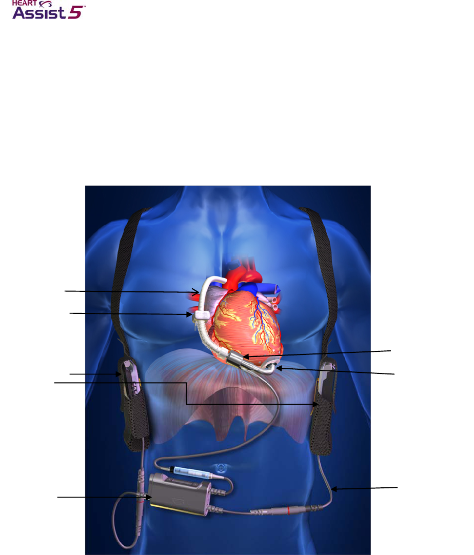
2–2 HeartAssist 5® VAD System Operator's Manual
Introduction
The VAD is a miniaturized, auxiliary heart pump, or ventricular assist device (VAD). The
VAD is 30 mm x 76 mm, weighs 92 grams (less than 4 ounces), and is designed to
provide increased blood flow to patients who suffer from heart failure. It is capable of
pumping in excess of 10 liters per minute.
The HeartAssist 5® VAD is intended for patients with a BSA > 1.5, and the HeartAssist
5® LBSA VAD is intended for patients with a BSA < 1.5. All of the material presented in
the HeartAssist 5® VAD System Operator’s Manual is true for both devices.
Figure 2-1. The HeartAssist 5® VAD System
Outflow Graft
Flow Probe
Battery Pockets
and Batteries
Controller
Pump
Inflow Cannula
Percutaneous
Cable
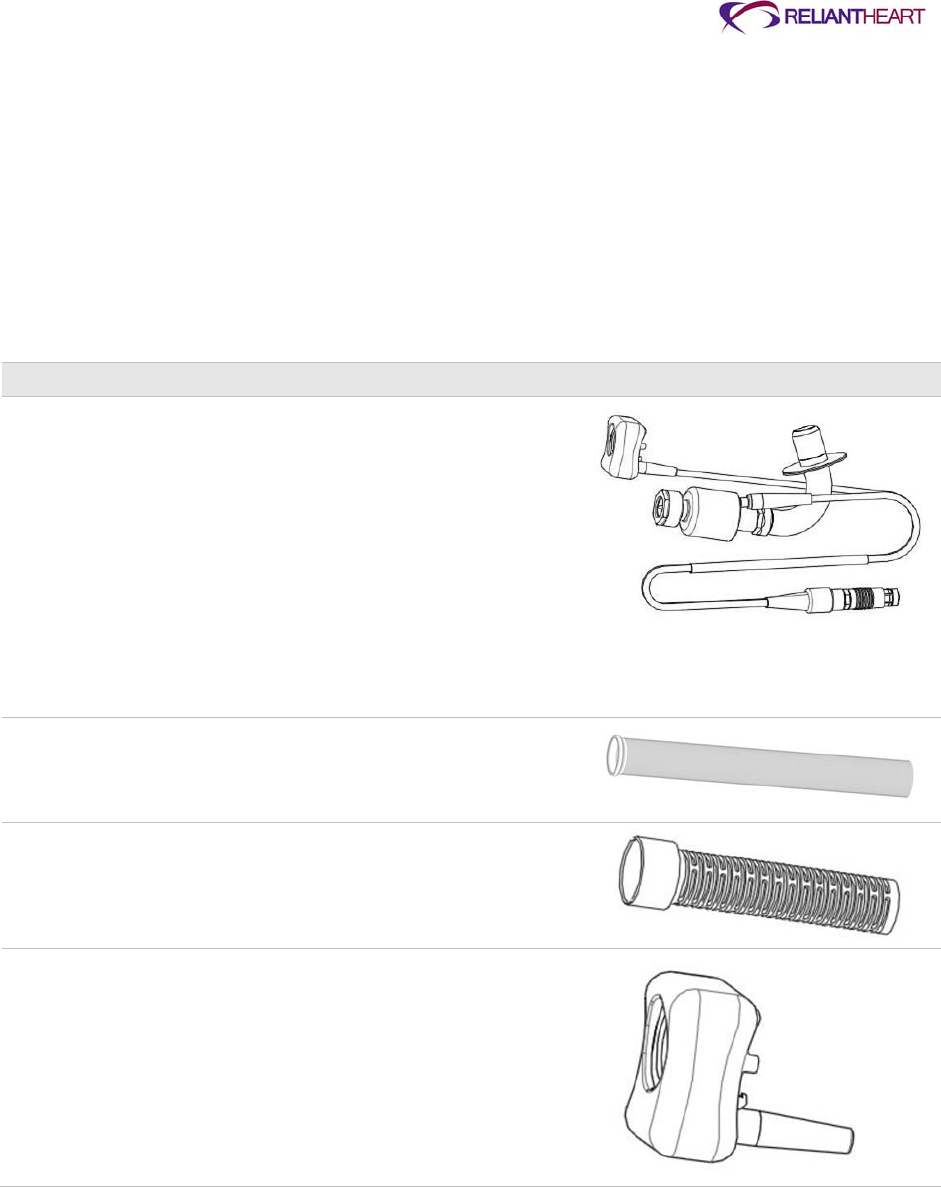
ReliantHeart Confidential – Medical Personnel and Technical Staff 2–3
System components
The HeartAssist 5® VAD System consists of implantable components, wearable
components, and accessories as well as patient and hospital documentation.
Tables 2-1 through 2-4 list the components that are used throughout your time on VAD
support.
Implantable components
Table 2-1 lists the implanted HeartAssist 5® VAD System components.
Table 2-1. Implantable components
Component Description Example
HeartAssist 5®
VAD (VAD) The VAD with inflow cannula, wedge nut, flow
probe, and percutaneous cable attached. The
VAD is connected to the heart via the inflow
cannula, which is inserted into the apex of the left
ventricle.
A three-phase electric motor is integrated in the
VAD and driven by the Controller. The VAD is
connected to the Controller via the percutaneous
cable that is passed through the skin at the exit
site.
The VAD is fully implanted in the patient (with the
exception of a portion of the percutaneous cable),
and thus does not have a user interface.
The VAD is the CF Applied part.
Outflow graft The outflow graft consists of a pre-clotted gelatin
weave graft. It is attached to the distal end of the
VAD with the wedge nut and is anastomosed to
the ascending aorta.
Graft protector The graft protector is a plastic cover that attaches
to the flow probe and protects the outflow graft.
Flow probe The flow probe is a custom ultrasonic real-time
flow sensor. It accurately measures the flow
passing through the graft.
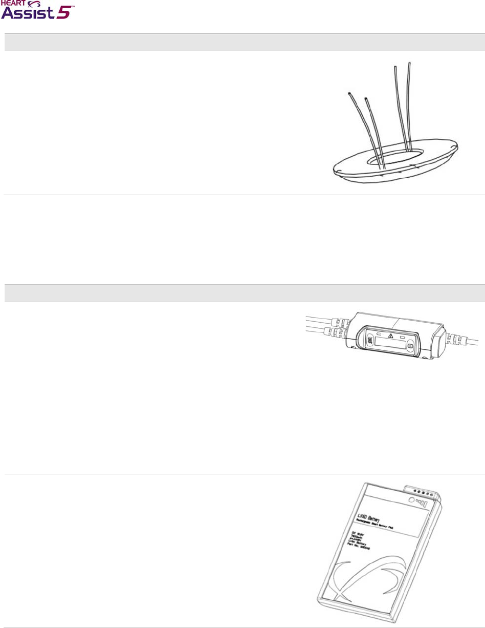
2–4 HeartAssist 5® VAD System Operator's Manual
Component Description Example
Sewing ring The sewing ring is a silicone ring wrapped in
polyester with drawstring Prolene “0” sutures
used to attach the inflow cannula to the apex of
the left ventricle.
Wearable components
Table 2-2 lists the HeartAssist 5® VAD System components that you wear.
Table 2-2. Wearable components
Component Description Example
Controller The Controller regulates the speed and supply of
power to the VAD, displays current operating
parameters, and provides visual and audible
alarms.
The Controller contains the power management
system, the motor controller, data acquisition
memory, software, a microprocessor, and
ultrasonic flow measurement system, and a
system to provide GSM cell phone connectivity to
transmit pump data for remote monitoring.
The Controller includes two battery cables and
one driveline cable for the VAD connection.
ReliantHeart supplies a spare Controller with
each patient to allow for Controller exchange in
emergency situations.
Lithium ion Each battery supplies power to the VAD for up
7.5 hours. The battery includes a button indicator
consisting of LEDs which indicate the charge
level of the battery.
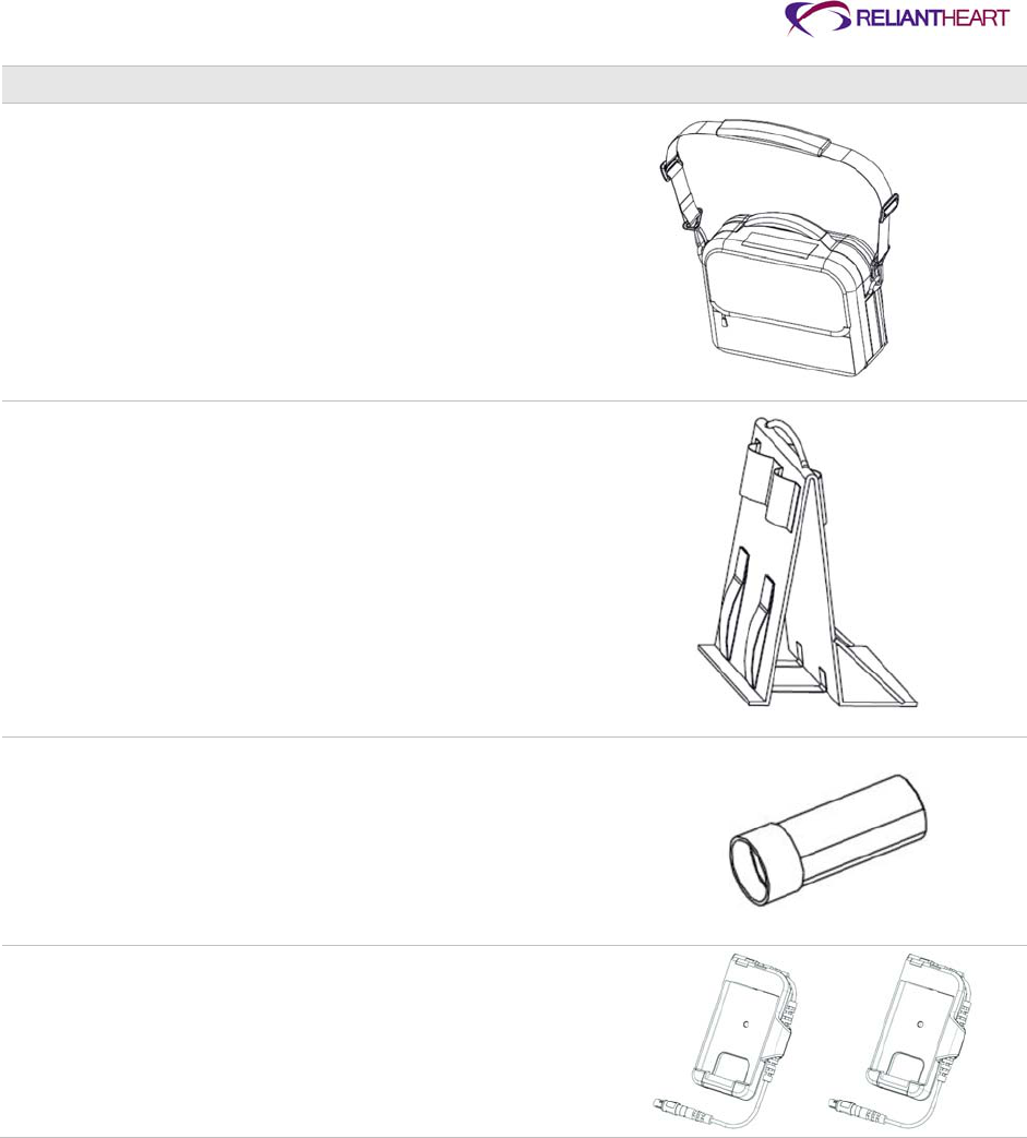
ReliantHeart Confidential – Medical Personnel and Technical Staff 2–5
Component Description Example
VADPAK The VADPAK carries the VADPAK Insert, which
contains the Controller and two battery pockets
with batteries inserted.
VADPAK Insert The VADPAK Insert is a reinforced fabric
organizer for the Controller, battery pockets,
batteries, and associated cables. It allows you to
easily manage and transport the HeartAssist 5®
VAD System during everyday use.
Defibrillation
cover The defibrillation cover protects the patient from
harm if defibrillation is needed. It is not intended
to secure the percutaneous cable to the
Controller cable. The defibrillation cover does not
protect against fluid ingress.
Battery pockets The battery pockets connect the batteries and all
external power sources to the Controller. The
battery pockets have an integrated quick release
feature to allow for easy removal of the batteries.
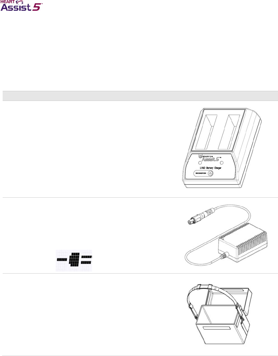
2–6 HeartAssist 5® VAD System Operator's Manual
Accessories
Tables 2-3 and 2-4 describe the patient and hospital accessories available for the
HeartAssist 5® VAD System.
Patient accessories
Table 2-3 lists the HeartAssist 5® VAD System patient accessories.
Table 2-3. Patient accessories
Component Description Example
LVAD Battery
Charger The LVAD Battery Charger charges and
reconditions the system batteries. The charger
contains LED status indicators. The charger
requires up to 3.5 hours to fully charge a battery
and between 10 – 14 hours to recondition a
battery.
Independent
Power Supply The Independent Power Supply provides mains
(AC) electricity to the Controller. When you are
using the Independent Power Supply, the VAD
is not consuming battery power, and the
Controller displays the external power indicator
(a plug symbol) on the front panel. This symbol
indicates that the system is using an external
power source:
Shower bag The shower bag protects the VADPAK Insert,
Controller, cables, battery pockets, and batteries
while you shower.
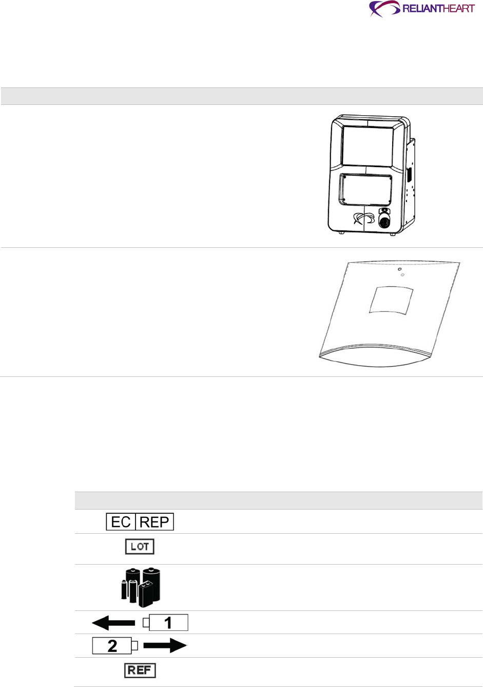
ReliantHeart Confidential – Medical Personnel and Technical Staff 2–7
Hospital accessories
Table 2-4 lists the components used by the hospital staff.
Table 2-4. Hospital accessories
Component Description Example
HeartAttendant® The HeartAttendant® is used to program the
Controller, displays VAD performance and data,
and provide mains (AC) power to the Controller.
It can transmit data via an internet connection.
This device is password protected. It is
connected to the Controller via the
HeartAttendant® connector cable.
Surgery pouch The surgery pouch is a non-sterile, disposable
pouch that holds the Controller during surgery.
Symbols used in labeling
Table 2-5 lists the symbols used in ReliantHeart product labeling and provides a
description of their meaning.
Table 2-5. Product labeling symbols
Symbol Description
Authorized EC representative in the European Community
Batch code
Batteries enclosed
Battery connection – battery 1
Battery connection – battery 2
Catalog or reference number
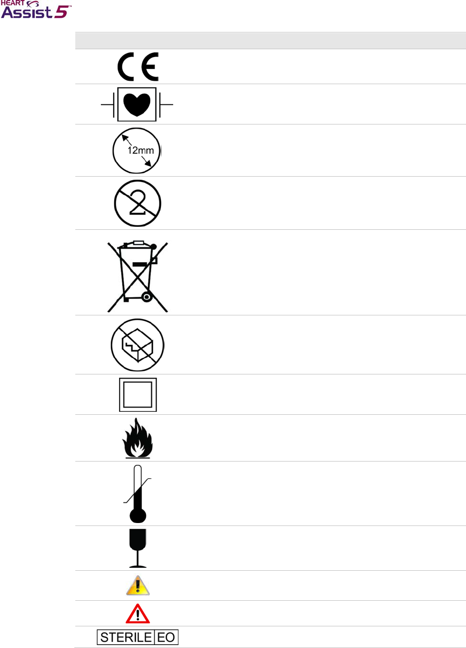
2–8 HeartAssist 5® VAD System Operator's Manual
Symbol Description
CE mark
Defibrillation proof – type CF applied part
Diameter
Do not reuse; applies to single-use devices
Do not discard in trash
Do not use if damaged
Double insulated
Fire hazard
For use within temperature limits
Fragile
General caution
General warning
Item showing sterilization method: ethylene oxide
ReliantHeart Confidential – Medical Personnel and Technical Staff 2–9
Symbol Description
Latex free
Manufactured on YYYY-MM
or
Manufactured on YYYY-MM-DD
Manufacturers name and address
Nationally recognized safe testing lab label
Serial number
Use by YYYY-MM
Or
Use by YYYY-MM-DD
See instructions for use
If batteries are part of an ongoing clinical trial, contact customer
support (see page iii); otherwise, dispose of batteries in
accordance with “Disposal”.
MR Unsafe

2–10 HeartAssist 5® VAD System Operator's Manual
Documentation
Table 2-6 lists the documentation available for the HeartAssist 5® VAD System.
Table 2-6. HeartAssist 5® VAD System documentation set
Document Audience Description
The HeartAssist 5® VAD System
Patient User’s Manual Patients and caregivers This manual is a user guide intended for
HeartAssist 5® VAD System patients and
caregivers. It contains descriptions and usage
information for the end user of the HeartAssist 5®
VAD System.
The HeartAssist 5® VAD System
Operator’s Manual
(this book)
Medical personnel and
technical staff This manual is a user guide intended for
HeartAssist 5® VAD System surgeons, technical
support staff, and other medical personnel. It
contains detailed instructions for surgical
procedures and system setup for HeartAssist 5®
VAD System medical and technical staff.

ReliantHeart Confidential – Medical Personnel and Technical Staff 3–1
Chapter 3
Initial Setup, Testing and Surgery
In this chapter
Introduction ................................................................................................................................... 3-3
Setting up the HeartAttendant® .................................................................................................... 3-3
Preparation for implant .................................................................................................................. 3-3
Preparing for implant 24 hours prior to surgery ............................................................... 3-3
Setting up the primary Controller .................................................................................... 3-7
Preparing the VAD for surgery ......................................................................................... 3-8
Surgical implantation ................................................................................................................... 3-15
Preparing the VAD pocket (when necessary) ................................................................ 3-15
Applying the apical fixation ring ..................................................................................... 3-16
Inserting the inflow cannula ........................................................................................... 3-16
De-airing the HeartAssist 5® VAD ................................................................................. 3-17
Tunnelling the driveline .................................................................................................. 3-17
Attaching the outflow graft to the aorta .......................................................................... 3-18
De-airing a second time ................................................................................................. 3-18
Connecting the percutaneous cable to the Controller .................................................... 3-19
Managing VAD performance immediately after starting the VAD .................................. 3-19
Post implant ................................................................................................................................ 3-20
Finalizing the surgery ..................................................................................................... 3-20
Transferring the patient out of the operating room ........................................................ 3-20
Setting VAD parameters ................................................................................................ 3-21
Patient management ................................................................................................................... 3-21
Required and optional patient equipment ...................................................................... 3-21
Adjusting the VAD speed ............................................................................................... 3-22
Managing the batteries .................................................................................................. 3-22
Managing general treatment issues ............................................................................... 3-22
Managing fluids, inotropes, and vasoactive medications............................................... 3-23
Controlling infection........................................................................................................ 3-24
Treating the exit site ....................................................................................................... 3-24
Controlling patient bleeding ........................................................................................... 3-24
Initiating anticoagulation therapy ................................................................................... 3-24
Identifying and correcting VAD stoppage ...................................................................... 3-25
Correcting regurgitant flow ............................................................................................. 3-25
Treating right heart failure .............................................................................................. 3-25
Diagnosing ventricular collapse ..................................................................................... 3-25
Ambulating patients........................................................................................................ 3-26
Sleeping ......................................................................................................................... 3-26

3–2 HeartAssist 5® VAD System Operator's Manual
Showering ...................................................................................................................... 3-26
Avoiding static electric discharge ................................................................................... 3-26
Patient discharge ........................................................................................................................ 3-27
Service ........................................................................................................................................ 3-27
Explanting the VAD ..................................................................................................................... 3-27
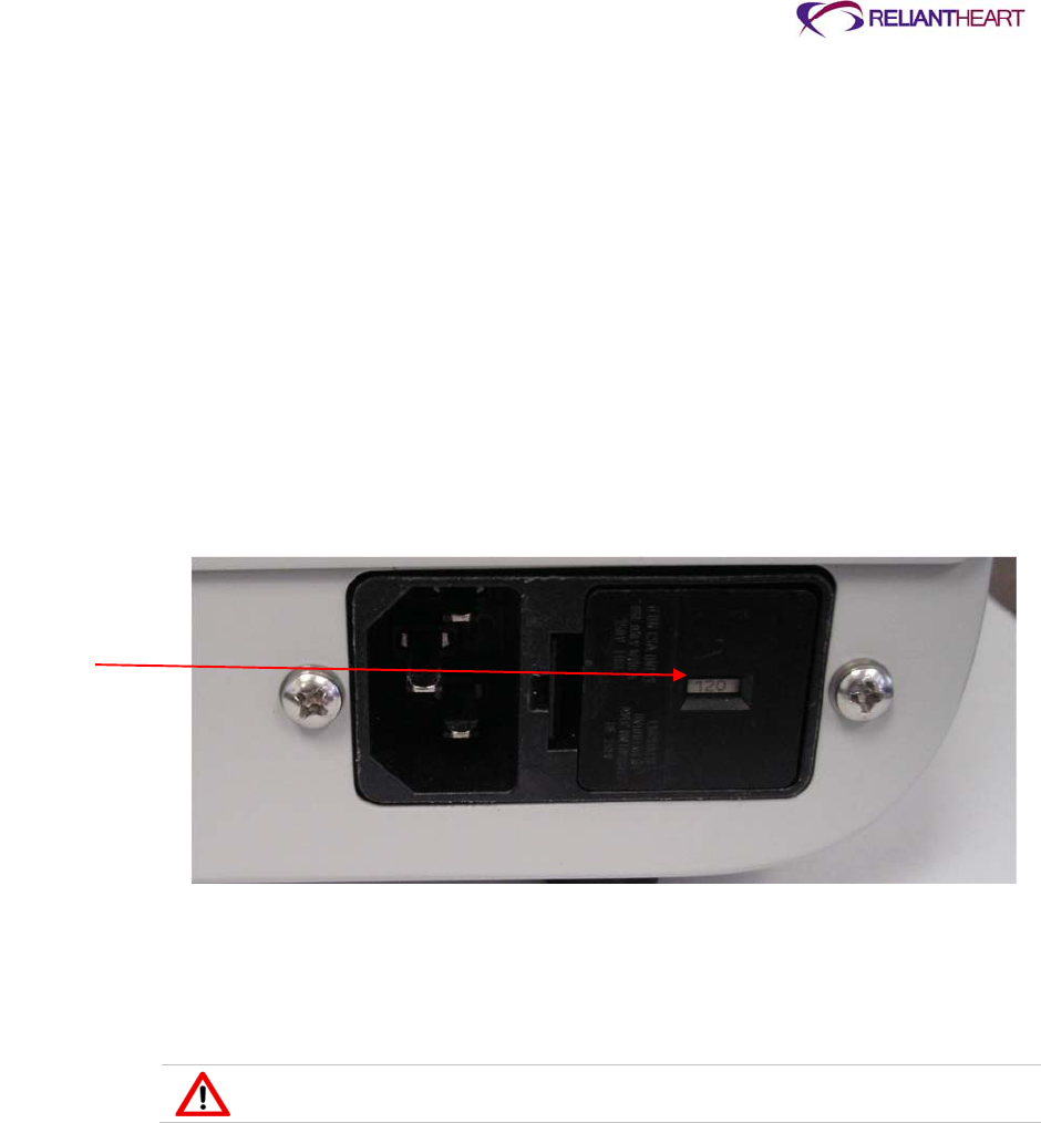
ReliantHeart Confidential – Medical Personnel and Technical Staff 3–3
Introduction
This chapter provides information on HeartAttendant® setup; preoperation, operation,
and postoperation procedures; patient management; patient discharge; equipment
service; and explantation.
Setting up the HeartAttendant®
The HeartAttendant® ships with the AC power setting appropriate to the country of use,
preset for either North America 115VAC or Europe 230VAC. Use the following steps to
verify the AC power setting and to activate the HeartAttendant®.
1. Check the AC power input on the back of the HeartAttendant® to ensure that the
power setting is appropriate.
See Figure 3-1. If the setting is not appropriate, contact ReliantHeart.
Figure 3-1. AC power setting
2. Plug the main power cord into the AC power input on the back of the
HeartAttendant®.
3. Plug the power cord into the AC power source.
The HeartAttendant® should boot up to the PATIENT screen within 40 seconds.
Only use power cords supplied by ReliantHeart.
Preparation for implant
Non-sterile preparations for the HeartAttendant®, implant and patient kits for surgery, and
the Controllers are outlined in the following sections.
Preparing for implant 24 hours prior to surgery
Perform the following non-sterile tasks 24 hours before implanting the VAD.
AC Power
Setting

3–4 HeartAssist 5® VAD System Operator's Manual
Preparing the HeartAttendant®
The operator must verify HeartAttendant® settings prior to surgery. If the settings are not
correct, the operator must adjust them. Use the following steps to verify or adjust
HeartAttendant® settings.
1. Verify or set the correct date and time. See “Time” and “SYNC TIME button” on page
5-16.
2. Verify or set the tech mode password. See “SET PASSWORD button” on page 5-17.
Preparing the implant and patient kits for surgery
The operator must ensure the contents of the implant kits and the patient kit. A backup
implant kit must be present and complete before surgery proceeds.
If any of the contents of the surgical kit packaging are opened, damaged, or
compromised before use at surgery, use the backup kit packaging. Return the
compromised surgical kit packaging with contents to ReliantHeart.
ReliantHeart ships the HeartAssist 5® VAD within protective packaging. The inner
package is sterile while the outer package is not. Do not open the inner package outside
of the sterile field.
Sterilizing the surgical tools
Perform the following tasks to ensure that the surgical instruments are sterilized properly.
1. Remove the coring blade and tip from the surgical kit packaging and place it in the
tool sterilization pouch.
2. Remove the surgical tools and the anatomic fit VAD from the shipping box, if
applicable, and place the individual tools in the tool sterilization pouch.
3. Verify that the sterilization pouch contains the following instruments:
Percutaneous introducer (4 pieces)
Anatomic fit VAD, regular or low BSA (2 pieces)
Coring blade (2 pieces)
Coring blade handle (3 pieces)
Wedge nut wrench (1 piece) See Figure 3-2 for an example of the surgical tools.
See Figure 3-2 for an example of the surgical tools.
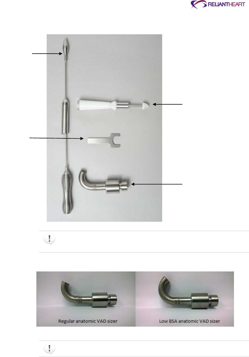
ReliantHeart Confidential – Medical Personnel and Technical Staff 3–5
Figure 3-2. Assembled HeartAssist 5® VAD surgical tools
The coring blade and tip are single use items only. Discard previously used blades
and tips. The other surgical tools and the anatomic fit VAD components can be used
a maximum of 20 times before disposal is recommended.
Figure 3-3. Anatomic VAD Sizer
The anatomic VAD sizers display either a normal human size or small human,
surrounded by a box, denoting either normal size or low BSA size, respectively.
Percutaneous
Introducer
Wedge Nut
Wrench
Coring Blade
(including blade
and tip) and
Coring Blade
Handle
Blade and Tip
supplied with each
VAD
Regular size
Anatomic Fit VAD

3–6 HeartAssist 5® VAD System Operator's Manual
4. Steam sterilize disassembled surgical tools in double-pouched paper or Mylar
pouches at either 132 °C for ten minutes or at 134 °C for five minutes using
parameters in ANSI/AAMI ST42, ANSI/AAMI ST46, ISO 17665-1, and ISO 17664-
2004.
Surgery may not proceed unless backup sterilized tools are available.
5. Following the sterilization process, assemble the surgical tools in a sterile
environment.
Charging the 12-volt Lithium Ion batteries
Fully charge VAD batteries using the LVAD Battery Charger before surgery. ReliantHeart
recommends placing the batteries in the charger the night before surgery.
Setting up the Controllers immediately before surgery with the
HeartAttendant®
Using the HeartAttendant®, perform the following steps a few minutes before surgery for
primary and backup controllers.
Perform the following steps on the HeartAttendant® to set Controller parameters.
1. Connect the HeartAttendant® connector to the backup Controller.
Initially the HeartAttendant® does not recognize the Controller and displays the
message Patient Data Directory not found. Please enter all required patient data
and save.
2. Enter patient data information for only the first four fields.
This display consists of a dialog box with seven boxes, four that are editable and
three that should not be edited. The data specified in these boxes are listed below.
Editable boxes include the following:
– Patient ID
34 character maximum; the following characters are disallowed:
\ / : ?< > | _ *
– Hospital ID
10 character maximum
– Implant Date
8 character maximum in DD/MM/YY format
Boxes that should not be edited include the following:
– Pump ID
– Controller
– Flow Probe Data
3. When you have completed your entries in the four editable boxes, press the Save
button.
The emergency alarm activates.
4. Temporarily deactivate the alarm using the following steps:
a. On the Controller, simultaneously press the Alarm Silence button and the Scroll
Display button until the Controller emits a beep and the display flashes. The
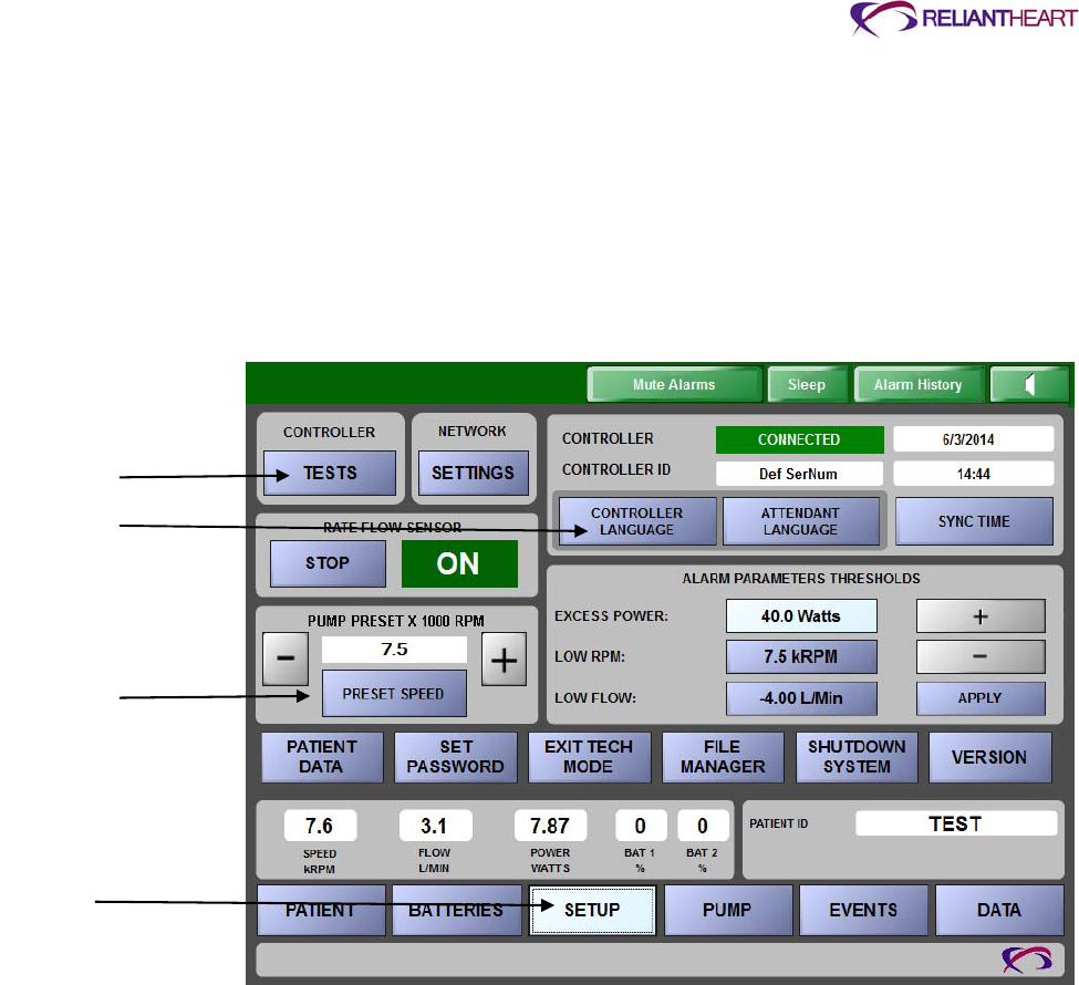
ReliantHeart Confidential – Medical Personnel and Technical Staff 3–7
Controller front panel displays the deactivation time options (between 1– 4 hours)
and the + and – buttons.
b. Choose the amount of time to deactivate the alarm by pressing either the + or the
– button on the Controller front panel. With the alarms silenced, you can prepare
the Controller for use.
5. Download your language to the Controller from the SETUP screen.
This process requires a couple of minutes. See “CONTROLLER LANGUAGE button”
on page 5-15 for more information.
Figure 3-4. SETUP screen
6. Run all Controller tests from the HeartAttendant® SETUP screen by pressing the
TESTS button then pressing the Execute Test button.
7. Preset the VAD RPM to 7,500. Wait 16 seconds after pressing this button before
initiating any other HeartAttendant® commands. See “Presetting VAD speed” on
page 5-16 for more information.
8. Disconnect the Controller from the HeartAttendant®, and repeat steps 1 – 7 for the
primary Controller.
9. Leave the primary Controller attached, and follow the steps in the next section,
“Setting up the primary Controller.”
Setting up the primary Controller
Using the HeartAttendant®, perform the following steps to prepare the primary controller
and VADPAK a few minutes before surgery.
1. Connect the battery pockets to the primary Controller.
See “Connecting a battery pocket to the Controller” on page 4-24.
2. Insert the fully charged batteries into the battery pockets.
Controller Tests
Button
Controller
Language Button
Preset Speed Pane
Setup Button

3–8 HeartAssist 5® VAD System Operator's Manual
See “Changing a battery” on page 4-26.
3. Place the Controller and battery pockets, containing the fully charged batteries, into
the VADPAK Insert.
See “Setting up the VADPAK Insert” on page 4-16.
4. Place the VADPAK Insert into the plastic bag provided in the surgery kit.
5. Insert the tie wrap through the hole in the bag and the handle on the VADPAK Insert.
6. Close the bag around the cables coming out the bottom of the bag.
7. Move the HeartAttendant® to a convenient position near the operating table.
8. Hang the surgery pouch on the right-hand side of the operating table near the site
where the percutaneous cable will exit the patient.
Leave the HeartAttendant®
connected to the Controller with the HeartAttendant®-to-
Controller cable draping below the operating table.
The Controller is now ready to be connected to the patient in stop mode.
The primary Controller to be connected to the patient should be powered up and
attached to the operating table in stop mode (PUMP OFF on the alarm status bar).
The wireless transmitter in the Controller will be automatically disabled when
connected to the HeartAttendant®. Patient or caregiver will have to manually
enable the wireless transmitter after connection to the HeartAttendant® is
terminated.
Preparing the VAD for surgery
Use the following instructions to ensure that the HeartAssist 5® VAD is ready for surgery.
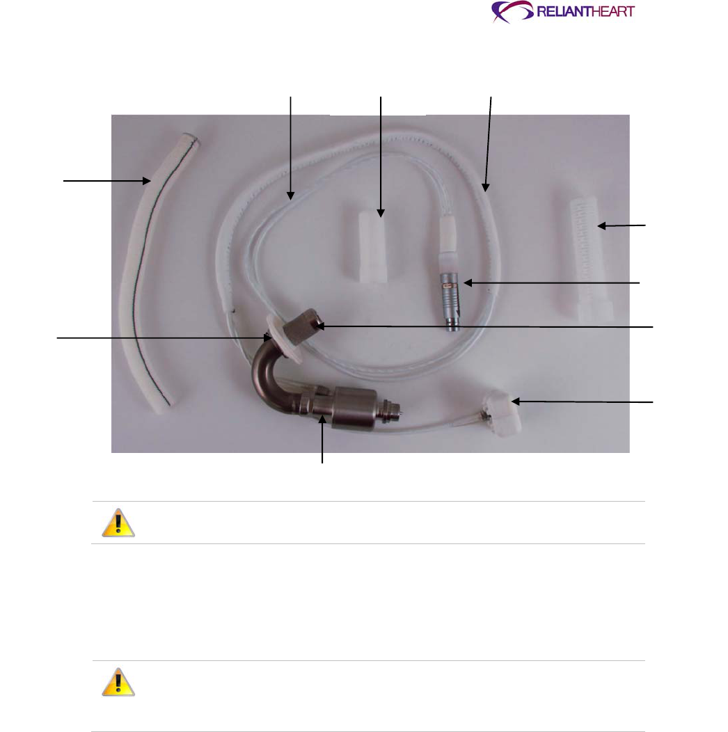
ReliantHeart Confidential – Medical Personnel and Technical Staff 3–9
Figure 3-5. VAD Components
Do not drop the VAD. If the VAD falls, do not use the VAD.
Assembling the sterilized surgical accessories
Use the following instructions to prepare the contents of the HeartAssist 5® VAD blister
package for surgery.
Prior to removing the contents from the sterile HeartAssist 5® VAD blister
package, inspect the blister package for damage, broken seals, or loose
debris. If the package contains any damage, broken seals, or loose debris, do
not use the VAD.
1. Remove the contents from the inspected sterile HeartAssist 5® VAD blister package,
and prepare to place the contents in the sterile field.
2. Place the sterilized surgical accessories (as described in the following list) in the
sterile field.
HeartAssist 5® VAD
– attached wedge
– attached wedge nut
Surgical kit
– sewing ring
Outflow Graft
Sewing Ring
Percuaneous
Cable
Percutaneous
Connector
Cover
Dacron Sheath
Graft Protector
Percutaneous
Cable
Connector
Inflow Cannula
Flow Probe
HeartAssist 5 VAD

3–10 HeartAssist 5® VAD System Operator's Manual
– cable cap
– graft protector
Coring blade handle
– two plastic pieces
– one metal piece
Coring blade
– one metal circular blade
– one plastic tip
Percutaneous introducer
– metal handle
– metal shaft
– metal point
– metal cover
Anatomic fit VAD (regular and low BSA sizes)
VAD test extension cable (gray, approximately 0.8 meters)
Priming the VAD
To expel the air from the VAD, perform the following tasks.
1. Place the VAD in a basin of sterile water with 5% dextrose (minimum of 10 cm deep).
2. Tip the submerged VAD to ensure that the inflow cannula is in a position to allow all
of the air to escape.
See Figure 3-5 for an example of the VAD.
Figure 3-4. VAD preparation

ReliantHeart Confidential – Medical Personnel and Technical Staff 3–11
Testing the VAD
Perform the following steps to verify the integrity of the VAD.
During testing of the VAD, it is imperative to completely submerge the VAD
during starting. Do not allow the inflow cannula to ingest air. A dry start will
damage the VAD.
1. Connect the sterile VAD test extension cable to the percutaneous connector of the
VAD.
2. Connect the backup Controller to an empty battery pocket.
Have a charged battery ready to be inserted into the battery pocket.
Do not place a battery into the battery pocket until you reach step 6. Failure to
follow these instructions can result in the VAD starting prematurely, causing
damage to the VAD.
3. Give the circulating assistant the distal end of the sterile VAD test extension cable.
4. Connect the test cable to the Controller and the empty battery pocket.
5. Before starting the VAD, firmly hold the VAD in the bottom of the basin.
Do not occlude the inflow cannula.
6. At the instruction of the sterile assistant, insert the battery into the battery pocket to
start the VAD.
7. Allow the VAD to run for five minutes.
If squealing noises are present when you test the VAD before implant, remove
the battery, and do not use the VAD. Prepare the backup VAD for implant.
Return the damaged VAD to ReliantHeart.
Once the VAD has started, allow it to run for five minutes to ensure complete
evacuation of air within the bearings.
If the VAD stops after powering up with the Controller, do not use the VAD
under test in surgery. Prepare the backup VAD for implant. Return the
damaged VAD to ReliantHeart.
Fluid flow exiting the VAD and the absence of an emergency alarm within five
minutes signify that the VAD is operating properly.
8. Disconnect the sterile VAD test extension cable from the percutaneous connector,
and give it to the circulating assistant.
9. Disconnect the backup Controller from the battery pocket, and replace the Controller
protective caps.
10. Set backup controller aside.
11. Remove the VAD from the basin.
12. Inspect the basin for loose debris, and then set it aside.
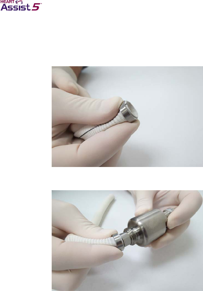
3–12 HeartAssist 5® VAD System Operator's Manual
Attaching the graft to the VAD
Use the following instructions to attach the graft to the VAD and the flow probe.
1. Slide the wedge onto the graft, and seat the graft ring into the wedge, as shown in
Figure 3-7.
Figure 3-7. Seating the ring into the wedge
2. Slide the end of the graft with the wedge onto the end of the VAD.
Figure 3-8. Attaching the graft with wedge to the VAD
3. Slide the nut over the graft and the wedge and tighten to a loose finger-tight fit.
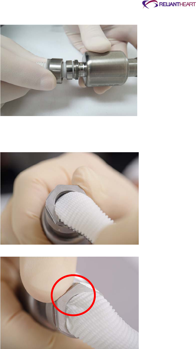
ReliantHeart Confidential – Medical Personnel and Technical Staff 3–13
Figure 3-9. Sliding the wedge nut over the wedge
4. Gently pull any pinched graft that occurs between the nut and the wedge.
When the graft is installed correctly and not pinched, the wedge is visible when you
gently pull the graft away from the nut.
Figure 3-10. Correct: graft free
Figure 3-11. Incorrect: graft pinched between the nut and the wedge
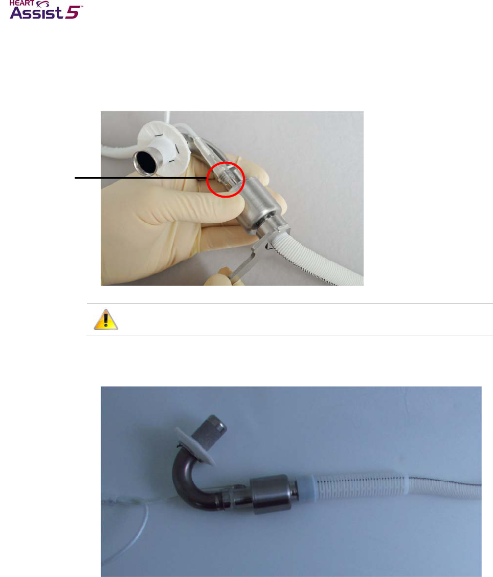
3–14 HeartAssist 5® VAD System Operator's Manual
5. When you are sure that the graft is not pinched between the nut and the wedge,
tighten the wedge nut with the wedge nut wrench.
Do not hold the inlet cannula or the wire strain relief when tightening the nut. Only
hold the VAD housing as shown in Figure 3-12.
Figure 3-12. Tightening the wedge nut
Do not press on the power cable connection.
6. Slide on the graft protector until it snaps into place.
Figure 3-13. Attaching the graft protector
7. Slide the flow probe onto the graft, ensuring that the flow probe cable points in the
direction of the VAD, parallel to the VAD motor wires.
Power Cable
connection: Do
not press
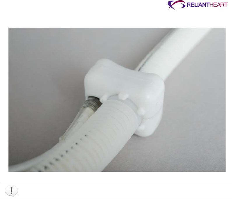
ReliantHeart Confidential – Medical Personnel and Technical Staff 3–15
Figure 3-14. Flow probe attachment to graft protector
Ensure that the graft protector prongs engage the flow probe when it is given to the
surgeon for implantation.
8. Place the protective cap onto the percutaneous connector.
9. Inspect the basin for loose debris before placing the VAD back into the basin.
10. Place the VAD back into the clean, inspected basin until it is requested by the
surgeon.
Surgical implantation
Use the following instructions as a guide for implantation of the VAD.
Preparing the VAD pocket (when necessary)
Use the following steps to prepare a pocket for the VAD if the surgeon determines that a
pocket is required.
1. Make a median sternotomy incision extended to the xiphoid process.
2. Use either the regular or low BSA anatomic fit VAD provided to determine if a pocket
is indicated.
If indicated, form a pocket in the rectus sheath beneath the rectus muscle.
3. Using the appropriate anatomic fit VAD, size the pocket making it large enough to
accommodate the HeartAssist 5® VAD.
To minimize the potential for bleeding or infection, do not make the pocket too large.
4. Open the pericardium to access the left ventricular apex.
3–16 HeartAssist 5® VAD System Operator's Manual
5. Divide the diaphragmatic attachment to the costal margin and extend both laterally
beyond the apex.
6. Prior to placing the patient on cardiopulmonary bypass, assess the patient for the
presence of a patent foramen ovale (PFO), and assess valve function using
transesophageal echocardiography.
7. If a PFO or tricuspid insufficiency is present, correct the defect before proceeding
with the VAD implant.
Applying the apical fixation ring
Use the following instructions to sew the apical fixation ring to the left ventricle.
1. Elevate the left ventricle so that the apex is exposed.
2. Select the insertion site for the inflow cannula.
The coring site selected should be slightly anterior to the apex and 2–3 cm left of the
anterior descending coronary artery.
3. Sew the apical fixation ring in place with 8–10 interrupted mattress sutures with large
Teflon pledgets. The suture size and type should be appropriately determined by the
Physician (ReliantHeart guidelines suggest double-armed 2-0 polypropylene mattress
sutures with large Teflon pledgests).
Do not use absorbable sutures throughout the implantation of the entire
HeartAssist 5® VAD system.
Do not enter the peritoneal cavity..
Use caution when applying the apical fixation ring or coring the ventricle in a
patient who has sustained a recent myocardial infarction in this area of the
heart.
Ensure that the VAD has the graft properly attached and has been tested prior to
implant.
Inserting the inflow cannula
Perform the following steps to insert the inflow cannula into the left ventricle.
1. With the apex exposed, use an 11 blade to make a full thickness cruciate incision
inside the apical ring.
2. Manually compress the ventricular apex to prevent bleeding if the ventricle is full or if
the heart is beating.
3. Insert the coring device into the left ventricle and extract a core of the apex.
Core with the coring blade’s orientation between the mitral valve and aortic valve
inflows.

ReliantHeart Confidential – Medical Personnel and Technical Staff 3–17
Apply the cutting edge of the coring blade to the epicardium and maintain pressure
while rotating the blade until the ventricular cavity is entered.
4. To confirm precise coring, examine apical tissue removed from the coring device.
5. Perform digital exploration to evaluate core position and ensure the absence of
potential obstruction to the inflow inside the ventricle (for example, a thrombus or
muscle remnant).
6. Clamp the outflow graft.
7. Insert the inflow cannula into the ventricle.
8. Tighten the two sets of purse strings on the apical fixation ring.
9. Using the previously placed polypropylene sutures, sew the sewing ring on the inflow
cannula to the apical fixation ring.
10. With two running sutures (ReliantHeart guidelines suggest uninterrupted 2-0
polyproplene suture), tightly sew together the apical fixation ring and the sewing ring
on the inflow cannula to prevent blood or air leakage.
You can apply additional Teflon or felt strips to further prevent leakage.
De-airing the HeartAssist 5® VAD
Perform the following steps to fill the left ventricle with blood and remove all of the air
from the VAD.
1. The perfusionist will fill the left ventricle completely from the bypass.
2. Elevate the VAD and outflow graft.
3. Allow the VAD and outflow graft to fill with blood from the ventricle by releasing the
clamp.
4. Reapply the clamp on the outflow graft.
5. Check the apical insertion site for bleeding.
Add reinforcing pledgeted sutures as needed (ReliantHeart guidelines suggest
continuous 2-0 polypropylene suture with Teflon or felt strip).
Tunnelling the driveline
Use the following steps to create a passage through the abdomen for the driveline.
If preferred, the driveline can be tunneled before the insertion of the inflow cannula
into the left ventricular apex.
1. Attach the handle, cover, and tip point to the percutaneous introducer.
2. Tunnel across the midline to exit through the skin in a convenient position above the
right iliac crest.
3. The surgeon can slightly bend the percutaneous introducer to ease the passage
across the abdomen.
Do not enter the peritoneal cavity.

3–18 HeartAssist 5® VAD System Operator's Manual
4. Ensure that the bend radius as the cable leaves the VAD housing is not sharp.
Provide a larger bend radius to prevent damage to the cable or wires.
5. Make a small incision where the percutaneous introducer tip will exit the abdomen.
6. Push the percutaneous introducer tip through the skin.
7. Remove the percutaneous introducer tip, and attach the handle to the distal end of
the percutaneous introducer.
8. Attach the driveline to the proximal end of the percutaneous introducer.
9. Pull the driveline through the tunnel, exiting the skin.
10. After the driveline is pulled through the tunnel, attach the protector cap.
The driveline will be passed off the table and connected to the Controller when the
VAD is ready for use, and it is time for the second de-airing, prior to initialization of
VAD support and weaning of cardiopulmonary bypass.
If the driveline is not immediately attached to the Controller, attach the cap protector
to the driveline.
Attaching the outflow graft to the aorta
Use the following steps to attach the outflow graft to the aorta.
1. Place the VAD into position, and measure the length of the outflow graft.
2. Trim the outflow graft at 45°angle and the appropriate length to ensure that the graft
lies under the right sternal border without kinking or overstretching.
If the graft is not accurately trimmed, use the backup graft (supplied separately). If
the graft is too long or too short, the graft might kink or stenose.
If the patient requires a VAD pocket, prevent kinking of the outflow graft protector
by properly placing the VAD and by ensuring that the graft is the proper length.
A portion of the right diaphragmatic costal margin might require release to place
the graft correctly without kinking.
3. Ensure that the flow probe placed on the outflow graft is immediately proximal to the
graft protector.
4. Place the partial occlusion clamp on the ascending aorta.
5. Make a longitudinal arteriotomy, and sew the graft to the lateral ascending aorta
using the suture size and type appropriately determined by the Physician
(ReliantHeart guidelines suggest 5-0 polypropylene sutures).
6. Repair any bleeding site (for example, a needle hole or a tear in the graft) by
suturing.
De-airing a second time
Perform the following steps to remove the air from the VAD again.
1. Place an 18-gauge needle in the outflow graft between the aortic anastomosis and
graft clamp at the highest point.
2. Temporarily release the aortic partial occlusion clamp.
This action fills the distal aortic graft with blood, and trapped air escapes through the
needle.
3. Re-clamp the aorta; then un-clamp the outflow graft.

ReliantHeart Confidential – Medical Personnel and Technical Staff 3–19
4. Intermittently start and stop the VAD.
Ensure that the ventricle is full during the second de-airing process.
5. After all of the air is released, remove the 18-gauge needle.
6. Oversew the needle hole using the suture size and type appropriately determined by
the Physician (ReliantHeart guidelines suggest 5-0 polypropylene sutures).
All entrapped air must be removed from the VAD blood pumping chamber and
conduits to reduce the risk of air embolus.
Place the needle vent in the outflow graft in the highest point in the lumen (anterior
side to optimize air removal).
Optionally, flood the surgical field with sterile saline to further minimize the risk of air
entry and possible embolization.
Connecting the percutaneous cable to the Controller
Use the following steps to connect the percutaneous cable to the Controller.
1. At the instruction of the sterile assistant or the surgeon, take the percutaneous cable
(just tunnelled through the skin and below the sterile field), and inspect the connector
for liquid and debris.
If you find debris within the connector, rinse with deionized water and blow dry with a
syringe or bulb.
2. Slide the white defibrillation cover onto the percutaneous cable, ensuring that the
smaller diameter is on, facing toward the patient.
3. Connect the percutaneous cable to the primary Controller, and hang it off of the
operating table.
4. Screw the defibrillation cover onto the connector of the Controller cable.
5. When the surgeon instructs, start and stop the VAD.
Managing VAD performance immediately after starting the VAD
Use the following steps after you start the VAD.
1. Report the VAD performance at the request of the surgeons.
If the flow signal is noisy (tracing is not smooth), verify that the received voltages for
either channel A or B are above 1 volt.
Use the PUMP screen to check the voltages.
2. If necessary, request additional sterile saline at the graft probe site.
3. Set the VAD RPM conservatively slow (7500 – 9000 RPM).

3–20 HeartAssist 5® VAD System Operator's Manual
Post implant
Perform the following procedures to complete the surgery after the VAD implantation is
complete.
Finalizing the surgery
Perform the final surgical procedures.
1. Decrease cardiopulmonary bypass flows slowly to maintain a cardiac index of at least
2.0 L/min/m
2
, being careful not to overload the right ventricle.
2. Maintain inotropic support for the right ventricle.
3. Ensure adequate preload to prevent ventricular collapse.
4. Use transesophageal echocardiography to assess the inflow cannula position.
5. If the inflow cannula position is acceptable, and when flows are adequate, wean the
patient from bypass.
6. Reverse heparin with protamine if indicated.
7. Re-evaluate VAD flow and cannula position with the chest closed before placing
sutures.
8. Consider covering the outflow graft and VAD/ventricular apex with an ePTFE
pericardial membrane or similar product to facilitate re-entry upon transplant.
9. Place drains in the VAD pocket and mediastinum.
10. Secure the driveline in place with a single suture.
Transferring the patient out of the operating room
Use the following instructions when you are ready to transport the patient from the
operating room to the intensive care unit and ready to transfer the HeartAssist 5® VAD
System from wall power to battery power via the HeartAttendant®.
The following instructions assume that fully charged batteries are already in the battery
pockets and mounted to the VADPAK Insert contained in the protective plastic bag. See
“Setting up the primary Controller immediately before surgery” on page 3-7.
1. Ensure that the other Controller cable is connected to a fully charged battery.
2. Disconnect the HeartAttendant® from the Controller port for transfer.
3. Connect the second battery.
4. Reconnect the HeartAttendant® once the patient is settled in the intensive care unit.
5. At the bedside, secure the protective plastic bag containing the VADPAK Insert with
the battery pockets, batteries, and Controller using one of the following methods:
Hang it from an intravenous IV pole.
Secure it to the bed with towel clamps.
Do not attach the protected VADPAK Insert to the bed rail. The motion of
lowering and elevating the bed rail can damage cables.

ReliantHeart Confidential – Medical Personnel and Technical Staff 3–21
Do not place the protected VADPAK Insert beneath blankets, sheets, or the
patient's body. The Controller must be kept uncovered to allow proper cooling.
Because the VAD outputs are strongly affected by increases in load and decreases
in preload, a portable blood pressure monitor can be used to gauge the effectiveness
of support during transport. The HeartAttendant® and arterial pressure lines can be
quickly re-attached upon reaching the ICU.
Setting VAD parameters
After surgery, use the following steps to make adjustments to VAD speed and alarm
values.
1. Adjust the VAD pump speed on the PUMP screen using the HeartAttendant®.
See “RPM INCREMENT buttons” on page 5-19.
2. Adjust the alarm values (flow and speed about 20% below the nominal values and
excess current to 16 watts).
3. Check and record the performance of the flow probe by evaluating received
amplitude on the FLOW L/Min waveform pane of the PUMP screen on the
HeartAttendant®.
See Figure 5-18 on page 5-18.
If you experience a device malfunction or have a complaint, contact ReliantHeart.
Patient management
This section presents an overview of the information required to maintain the patient
following implantation with the HeartAssist 5® VAD. For detailed patient management,
see the HeartAssist 5® VAD System Patient User’s Manual.
Required and optional patient equipment
Refer to Table 3-1 for information on required primary and backup equipment and
optional equipment for HeartAssist 5® VAD patients.
Table 3-1. HeartAssist 5® VAD System patient equipment
Component Primary
(required) Backup
(required) Optional Notes
Implanted HeartAssist 5® VAD
a
1 1
Controller
a
1 1
Rechargeable batteries 4 2 Four batteries are required; two
optional, additional units are
available if patient is discharged.
LVAD Battery Charger 1 1
HeartAttendant®
a
1 1 Available in the hospital
VADPAK 1

3–22 HeartAssist 5® VAD System Operator's Manual
Component Primary
(required) Backup
(required) Optional Notes
HeartAttendant® connector
cablea 1 1 Required for patient discharge
Shower bag 1 Available in the hospital
Battery pockets 2 Two primary battery pockets
Independent Power Supply 1
a ReliantHeart requires each active site to maintain one backup VAD for every three patients on VAD support.
Every patient must have a backup Controller and a backup HeartAttendant® connector cable immediately
available. Each active site must have at least one HeartAttendant® available for every three patients on the
device. LVAD Battery Charger devices must be available to charge batteries. The number of HeartAttendant®
devices varies with respect to the number of patients on the device, whether or not they are in an intensive
care unit, and whether or not they are taking out-of-hospital excursions. For implant, a hospital must have at
least two LVAD Battery Charger devices to allow for charging of the batteries to transport the patient from the
operating room.
Adjusting the VAD speed
Stabilize the patient before beginning these steps.
1. Adjust the VAD speed to a level that provides the desired forward flow without signs
of regurgitant flow or ventricular collapse.
2. Maintain the VAD speed level.
Employ mixed venous oxygen saturation to adjust VAD speed and flow, maintaining
mixed venous oxygen saturation between 60 – 70%.
Managing the batteries
Hospital staff must initially supervise battery management, and then, as appropriate,
transfer management to the patient. Batteries last 4.5 – 7.5 hours, depending on power
requirements.
Once the second battery alarm indicates that the battery has discharged to 25%, change
the batteries immediately. However, ReliantHeart recommends changing the first battery
immediately after it alarms at 25% discharge.
Managing general treatment issues
Flow across the VAD is, in large part, determined by the pressure gradient across the
VAD (from outflow to inflow). Therefore, VAD output is dependent upon changes in left
ventricular filling (preload) and systemic vascular resistance (afterload).
Although physician judgment and experience varies, proper care of a patient supported
by the VAD requires a thorough understanding of system operation, the patient's
condition, and the unique physiologic support provided by axial flow rotary devices.
The following treatment issues are critical to the achievement of the best outcomes in
patients supported by the VAD.
Preload and afterload
Close surveillance for physiologic, pathophysiologic, or iatrogenic changes in left
ventricular filling (preload) and systemic vascular resistance (afterload) is required
following implantation. Small increases in afterload or small decreases in preload can
result in diminished VAD flow, a reduction that can manifest in a clinically relevant

ReliantHeart Confidential – Medical Personnel and Technical Staff 3–23
decrease in perfusion. If inadequate ventricular filling occurs, increasing VAD speed does
not increase flow.
Perfusion
Standard methods for achieving adequate perfusion might not be helpful under all
physiologic conditions. As described above, if preload or afterload changes, perform an
immediate patient assessment that includes physical examination to confirm the
adequacy of peripheral perfusion.
In shock states, physical examination might not provide adequate evidence of perfusion
restoration. Right heart catheterization under conditions of hemodynamic instability is
highly recommended. Mixed-venous O2 saturation measured intermittently or
continuously provides the most sensitive guide to perfusion in post-implantation shock
states. If right heart catheterization is not possible, substitute a mixed-venous O2
saturation from a right atrial catheter.
Blood pressure
Under stable physiologic conditions, automated blood pressure monitoring devices
(oscillatory blood pressure) might not yield accurate blood pressure data. Use manual
auscultation of an extremity to gauge blood pressure. However, in circumstances where
the flow has minimal pulsatility (vasodilatory states), manual blood pressures can be
difficult to obtain. Doppler stethoscope technologies have been effectively employed to
obtain manual blood pressures when pulseless flow prevents palpation of pulses.
Right heart function
Maintain inotropes during the immediate post-operative period at pre-operative levels to
protect right heart function.
Right heart failure can occur at any time following implantation. Follow-up closely and
intervene with nitric oxide, vasodilators, diuretics, inotropic drugs, or right ventricular
assist as indicated.
Rehabilitation
The following measures help assure the patient’s success on VAD support.
Encourage early ambulation and resumption of dietary intake.
Encourage social and family support during rehabilitation.
Recommend exercise physiotherapy post-implantation.
Discourage excessive weight gain, which can produce a decline in device performance.
Managing fluids, inotropes, and vasoactive medications
Use the following guidelines to maintain flow, pressure, and volume.
Administer fluids to maintain a cardiac index of greater than 2.0 L/min/m2 while central
venous pressure and left atrial pressure are maintained less than 20 mm Hg.
Take all measures to maintain left ventricular filling. These measures include aggressive
replacement of volume lost and close vigilance of right heart function and pulmonary
vascular resistance.
Initially treat sudden decreases in pump flow with restoration of volume. If volume
replacement does not augment flow, rule out potential sources of bleeding. If these
measures do not restore adequate flow, evaluate right heart function, and institute
inotropic support as indicated.

3–24 HeartAssist 5® VAD System Operator's Manual
Immediately evaluate the patient and system upon any complaints of dizziness.
The attending physician has the discretion to treat post-implantation hypertension.
Although ACE inhibitors are recommended, any therapy that consistently maintains
mean arterial blood pressure less than 90 mm Hg is adequate.
Controlling infection
To prevent infection, administer a broad spectrum antibiotic during the first 48 hours
following implant following procedures similar to any open heart surgery. Then, organism-
specific antibiotics can be administered as needed based upon positive culture results.
Early extubation, early ambulation, and removal of patient monitoring lines help prevent
infection. To reduce the potential for infection, use nursing measures such as frequent
hand washing, and use aseptic technique when contacting invasive lines and when
changing the exit site dressing.
Use parenteral treatment with antibiotics and surgical drainage if evidence of pump
pocket infection exists. Fungal infection resulting from organisms such as Candida
species has been associated with vegetative growth on other VADs. Persistent systemic
fungal infection that is refractory to antimicrobial treatment might require VAD
replacement.
Treating the exit site
Perform daily exit site care using a persistent antiseptic cleansing agent such as
chlorhexidine-containing scrub solutions. Dry the site following aseptic cleansing to avoid
tissue maceration. Adhere to aseptic technique whenever the exit site is inspected,
dressed, or otherwise handled.
Keep the exit site clean and dry, and apply a sterile bandage daily.
Prophylactic topical agents, such as silver sulfadiazine or polymixinneomycin-
bacitracin, are not typically used as these ointments applied to the exit site can
macerate the tissues and degrade the exterior cable.
Movement of the percutaneous cable should be minimized at the exit site.
Controlling patient bleeding
Bleeding is a common complication of VAD implantations in general. Carefully monitor
chest tube output. Perform routine measurement of partial thromboplastin time,
prothrombin time, INR, fibrinogen, and platelet count. Administer blood products as
needed to correct hematologic abnormalities. Consider surgical re-exploration if chest
tube bleeding exceeds 100 ml/hour after restoring coagulation factors.
Initiating anticoagulation therapy
Initiate anticoagulation therapy in VAD patients after chest tube bleeding stops (usually
48-72 hours after implantation). Optionally, start intravenous heparin or low molecular
weight heparin at this time, and continue the therapy until warfarin reaches therapeutic
levels. Start warfarin as soon as the patient can tolerate oral medications. Titrate warfarin
to maintain an INR between 2.0 and 3.0. Administer a platelet inhibitor, such as aspirin or
dipyridamole, in conjunction with warfarin therapy.

ReliantHeart Confidential – Medical Personnel and Technical Staff 3–25
Identifying and correcting VAD stoppage
Identify and correct the cause of a VAD stoppage as soon as possible. Rectify
mechanical or electrical causes of a VAD stoppage by applying the backup Controller.
Make all attempts to restart the VAD immediately. VAD stoppages that are a result of
thrombus might be preceded by increases in current and power with concurrent
decreases in flow.
If the VAD stops for more than three minutes, blood inside the VAD can
become stagnant. (This condition depends on the patient's coagulation
status.) If the blood inside the VAD becomes stagnant, restarting the device
presents a risk of stroke or thromboembolism.
Correcting regurgitant flow
Regurgitant flow can occur if the VAD stops or slows to less than 7,500 RPM. If speed
cannot be increased, or if regurgitant flow associated with a VAD stoppage results in
exacerbation of heart failure, the VAD might need to be exchanged. The VAD can also be
removed completely or left in place if the physician ligates the outflow graft.
If the VAD stops operating, the patient must seek immediate medical attention
to treat the potential physiologic consequences of regurgitant flow. Treatment
measures might include heparinization, standard interventions for acutely
decompensated congestive heart failure, or surgical exploration.
Treating right heart failure
Patients can suddenly develop right ventricular (RV) failure during or after device
implantation. The onset of RV dysfunction in these patients is often accompanied by the
inability of the left ventricle to fill and by drastically reduced flows across the VAD. Limited
filling is further exacerbated in the presence of right heart failure with an elevated trans-
pulmonary pressure gradient or high pulmonary vascular resistance.
Treatment for patients in right heart failure includes the administration of inotropes to
augment RV contractility, fluid management, hyperventilation, and pharmacologic
modulation of pulmonary vascular resistance. If these measures are not effective,
consider employing a right ventricular assist device.
Diagnosing ventricular collapse
When left ventricular filling is compromised by right ventricular failure, bleeding, or
hypovolemia, the ventricular chamber might collapse around the inflow cannula of the
VAD, further limiting flow. Recognize ventricular collapse by sudden flow reductions in
the presence of any of the above conditions and from the flow waveform displayed on the
HeartAttendant®. Figure 3-15 illustrates the characteristics of the flow waveform during
ventricular collapse.
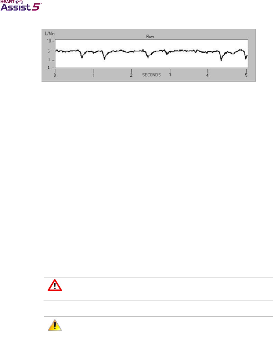
3–26 HeartAssist 5® VAD System Operator's Manual
Figure 3-15. Flow waveform during ventricular collapse
Ambulating patients
Once recovered from surgery, ambulate patients as much as possible. Instruct patients
on how to wear the VADPAK with Controller and batteries correctly. Whenever
ambulating away from the hospital room or home, the patient must carry a backup
Controller and at least two extra batteries. Once recovered, patients should be able to
perform exercise, although contact sports and swimming must be avoided.
Sleeping
Because patients can sleep through a battery alarm, patients must sleep tethered to the
HeartAttendant® or the Independent Power Supply. Do not adjust VAD operation to
accommodate for normal physiologic changes that occur with sleeping. Decreases in flow
and waveform patterns indicative of sucking (ventricular collapse) can occur overnight or
during the early morning if the patient becomes hypovolemic. If this situation occurs, the
patient must drink a glass of water prior to going to sleep.
Showering
Only showering is allowed, and showering may start after the clinician approves wound
site readiness. During showering, the Controller, batteries, and cables must be attached
to the VADPAK Insert. The VADPAK Insert must then be encased in the shower bag.
Avoiding static electric discharge
VAD patients must avoid static electric discharge. See Appendix D, “Manufacturer
guidance for environmental conditions” for more information on static electric discharge.
Avoid direct contact with devices with high voltage such as television or
computer screens since direct contact can damage the electrical components
of the HeartAssist 5® VAD System and can cause the VAD to stop.
Do not handle batteries by the connector pins because a strong static
discharge can cause a temporary loss of the charge status indicator. If you
experience a loss in charge status, place the battery in a ReliantHeart-supplied
charger and recondition the battery.

ReliantHeart Confidential – Medical Personnel and Technical Staff 3–27
Patient discharge
Patients discharged to home or a lower care facility must master concepts presented in
the HeartAssist 5® VAD System Patient User’s Manual. A trained companion is
recommended for patients going home with the HeartAssist 5® VAD System.
A device malfunction or other complication might necessitate emergency treatment;
therefore, arrangements with local physicians and emergency systems should be
established prior to patient release. Patients who live at distances away from the
implanting hospital that might prevent timely return for surgical intervention when
necessary might not be suitable for discharge.
Service
The HeartAssist 5® VAD System contains no user serviceable parts except for the
HeartAttendant® fuses. Return any component requiring repair to ReliantHeart for
service.
Explanting the VAD
Use the following steps to remove the VAD.
1. Expose the VAD, and dissect it free.
2. Place the patient on cardiopulmonary bypass, and establish flow.
3. Stop the VAD.
4. Dissect the percutaneous cable free, and cut the cable close to the VAD.
5. Pull the percutaneous cable at the exterior exit site to remove it.
6. Culture the cable as indicated.
7. Place the cable in the container for return to the manufacturer.
8. Cut the sutures between the sewing rings, and remove the inflow cannula from the
ventricle.
9. Ligate and cut the outflow graft close to the aorta.
10. Remove the entire device and cannula as a unit.
11. Culture the VAD as indicated.
12. Place the entire device in 10% formalin in the jar provided in the explant kit.
13. After 24 hours, replace the formalin with saline and ship the device back to
ReliantHeart.
It is a violation of law to ship formalin or formalin-containing jars. Ensure that
formalin is removed prior to shipment.

ReliantHeart Confidential – Medical Personnel and Technical Staff 4–1
Chapter 4
Controller, Batteries and VADPAK
In this chapter
Controller ....................................................................................................................................... 4-2
Overview .......................................................................................................................... 4-2
Controller display ............................................................................................................. 4-2
Controller sounds ............................................................................................................. 4-3
Controller messages and alarms ..................................................................................... 4-3
Battery indicators ............................................................................................................. 4-4
Flow sensor ...................................................................................................................... 4-4
Wireless radio antenna .................................................................................................... 4-4
Automatic fail-safe mode ................................................................................................. 4-5
VAD restart algorithm ....................................................................................................... 4-5
Controller replacement ..................................................................................................... 4-6
Controller safety check .................................................................................................. 4-13
Battery pockets ........................................................................................................................... 4-14
VADPAK ...................................................................................................................................... 4-16
VADPAK components .................................................................................................... 4-16
Setting up the VADPAK Insert ....................................................................................... 4-16
Connecting to external power ........................................................................................ 4-21
Power supply ............................................................................................................................... 4-22
Batteries ......................................................................................................................... 4-22
LVAD Battery Charger ................................................................................................... 4-28
Independent Power Supply ............................................................................................ 4-31
Connecting the Independent Power Supply to the Controller ........................................ 4-32
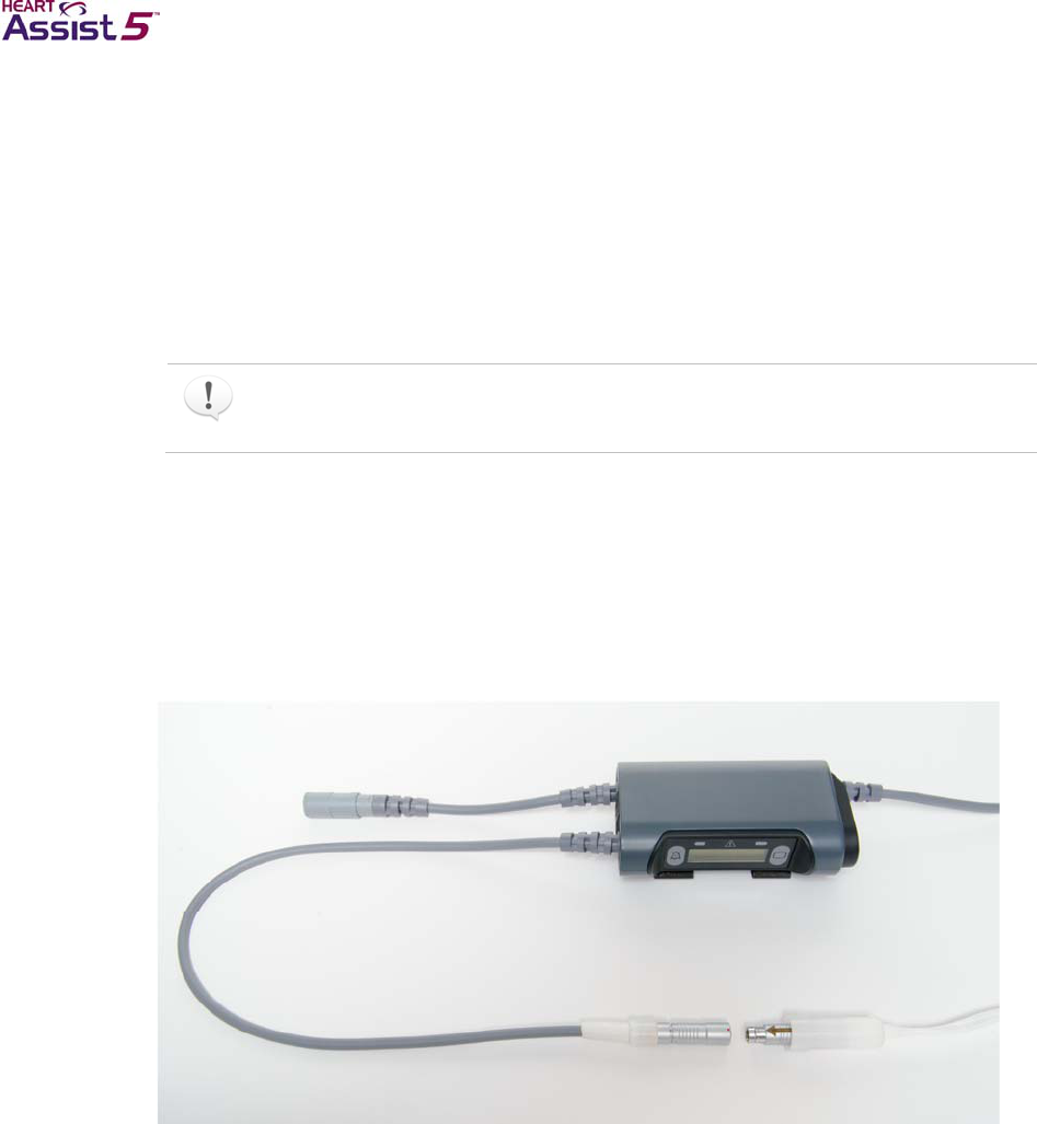
4–2 HeartAssist 5® VAD System Operator's Manual
Controller
The Controller provides power to run the VAD, and it displays VAD operating parameters
such as speed, flow, and power usage. It also displays remaining battery life and wireless
antenna status. The Controller is equipped with an internal radio for one-way wireless
transmission of data from the Controller to a secure server.
Users cannot adjust VAD operating parameters with the Controller. Use the
HeartAttendant® to adjust these parameters. The Controller is designed to be reliable
and easy to operate.
Users can choose the Controller option to transmit pump data by radio frequency
transmission, but activating this option is not required for the device to fulfill its
intended use or to meet the indications for use.
Overview
The Controller has two battery cables and one driveline cable for VAD connection. (See
Figure 4-1.) A liquid crystal display (LCD) is integrated into the Controller to display the
operational parameters of the VAD as well as any emergency or diagnostic alarms that
might occur. (See Figure 4-2.)
Figure 4-1. Controller
Controller display
The Controller front panel allows you manage alarms and to monitor system status.
Controller front panel features
The front panel of the Controller contains the following features:
LCD display
Two battery indicator light emitting diodes (LEDs)
Fail-safe and emergency mode indicator LED
The indicator LED is red when it activates. It is a solid red for fail-safe alarms, and it
flashes red for emergency alarms.
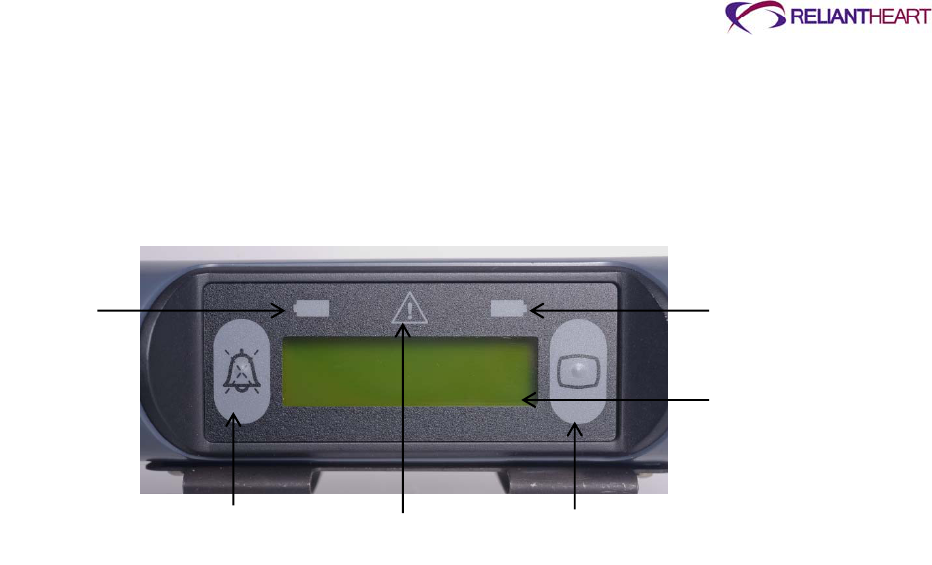
ReliantHeart Confidential – Medical Personnel and Technical Staff 4–3
Alarm Silence button
Scroll Display button
Figure 4-2 shows an example of the Controller front panel display.
Figure 4-2. Controller front panel
Adjusting Controller front panel brightness
Use the following steps to adjust the Controller backlight display brightness:
1. On the Controller, press the Scroll Display button, and hold it for five seconds.
The Controller display flashes when five seconds has passed.
2. Release the Scroll Display button.
The Controller front panel displays the + and – buttons and a slider, indicating the
current brightness level.
3. Press the + button to increase the brightness, or press the – button to decrease the
brightness.
The brightness slider indicates the new brightness level.
Controller sounds
The Controller emits three distinct sounds:
A diagnostic alarm is indicated by a slower beeping sound.
An emergency alarm is indicated by a faster, loud, ringing two-tone sound.
A Controller failure is indicated by a continuous tone.
Controller messages and alarms
The LCD screen on the front panel of the Controller displays three types of messages:
Standard messages
Diagnostic alarms
Emergency alarms
Standard messages
You can review seven standard information messages on the front panel of the Controller
by pressing the Scroll Display button. With the first press of the Scroll Display button, the
Battery 1
Indicato
r
Battery 2
Indicator
LCD Display
Scroll Display Button
Fail-safe and emergency
mode indicator LED
Alarm Silence
Button

4–4 HeartAssist 5® VAD System Operator's Manual
LCD backlights, and each subsequent press changes the display from one message to
the next in a continuous loop.
Emergency alarms
When the Controller displays an emergency alarm, the pump is stopped, the back light
automatically lights, an audible alarm sounds, and the emergency alarm indicator flashes
red. The Controller continues to audibly and visually alarm until you resolve the condition
causing the alarm. Pressing the Alarm Silence button has no effect. After you resolve the
condition causing the emergency alarm, the alarm automatically clears.
Diagnostic alarms
When the Controller displays a diagnostic alarm message, the back light automatically
lights, and an audible alarm sounds. Pressing the Alarm Silence button silences the
alarm.
Normal mode
In normal operating conditions with no alarms, the Controller LCD back light is off, and
the Controller displays standard message screen 1: battery status.
Battery indicators
The battery indicators on the top corners of the Controller front panel indicate three
different conditions for each battery.
For a description of these indicators, see Table 4-2, “Controller battery indicator
descriptions,” on page 4-26.
Flow sensor
The Controller contains an integrated flow sensor board that works with the implantable
flow probe. The quality of the flow signal is indicated by the received amplitude shown on
one of the screens of the Controller or on the HeartAttendant® PUMP screen. See Figure
B-4, “Standard message screen 4: flow probe received amplitude,” on page B-3 as an
example.
Any voltage above one volt on either channel A or B indicates that the flow signal quality
is acceptable. The flow sensor can be disabled on the SETUP screen of the
HeartAttendant®.
It is uncommon to disable the flow sensor feature during the normal use of the
HeartAssist 5® VAD System.
Wireless radio antenna
The Controller contains an internal wireless radio antenna for one-way, wireless,
machine-to-machine transmission of data from the Controller to a secure server. You can
disable the wireless antenna (the equivalent of placing the unit in airplane mode) as
needed.
Users have the option to allow the Controller to transmit pump data by radio
frequency transmission, but this option is not required for the device to fulfill its
intended use or to meet the indications for use.

ReliantHeart Confidential – Medical Personnel and Technical Staff 4–5
Use the following steps to enable and disable the wireless antenna:
1. On the Controller, press Alarm Silence button, and hold it for five seconds.
The Controller display flashes when five seconds has passed.
2. Release the Alarm Silence button.
The Controller front panel displays the + and – buttons and a wireless antenna
symbol. If the wireless radio antenna is disabled, the front panel also displays a
circle-backslash symbol.
3. Press the + button to activate the wireless antenna, or press the – button to disable
the antenna.
See Figure B-3, “Standard message screen 3: wireless antenna status,” on page B-3 for
examples of the wireless antenna Controller display.
Always disable the wireless radio antenna prior to boarding an aircraft.
Automatic fail-safe mode
ReliantHeart equips the Controller with features to provide fail-safe operation in the event
of failure of the internal central processing unit (CPU). The fail-safe mode operation
bypasses the CPU entirely and runs the HeartAssist 5® VAD at the last set speed. Fail-
safe mode operation activates automatically. In this situation, the Fail-safe and
emergency mode indicator LED on the Controller front panel changes from off to solid
red, and the Controller sounds a continuous high-pitched tone alarm. If these conditions
exist, replace the Controller, and contact ReliantHeart immediately for instructions.
VAD restart algorithm
The Controller contains a sophisticated restart algorithm that attempts to restart the VAD
in case of desynchronization or a VAD stoppage.
Automatic restart
If the VAD becomes desynchronized due to the loss of the back-EMF signal or other
momentary VAD stoppage, the Controller attempts to restart the VAD in approximately
two seconds. If this attempt occurs, the LCD displays PUMP STOPPED then PUMP
RESTARTING (only while the VAD is attempting to restart).
If the VAD restarts on the first attempt, the LCD screen clears and returns to the standard
message screen 1: battery status. If the VAD does not restart on the first attempt, the
PUMP STOPPED emergency alarm sounds as well as any additional alarms that can
diagnose why the VAD has stopped. (Examples of additional alarms include BOTH
BATTERIES DISCONNECTED or VAD DISCONNECTED.)
The Controller attempts to restart the VAD for approximately 60 seconds. First, the
Controller attempts to restart the VAD three times with a four-second pause between
each attempt. If these initial attempts are unsuccessful, the cycle is repeated two more
times with a 10-second pause between each set of attempts. The Controller attempts to
automatically restart the VAD up to nine times.
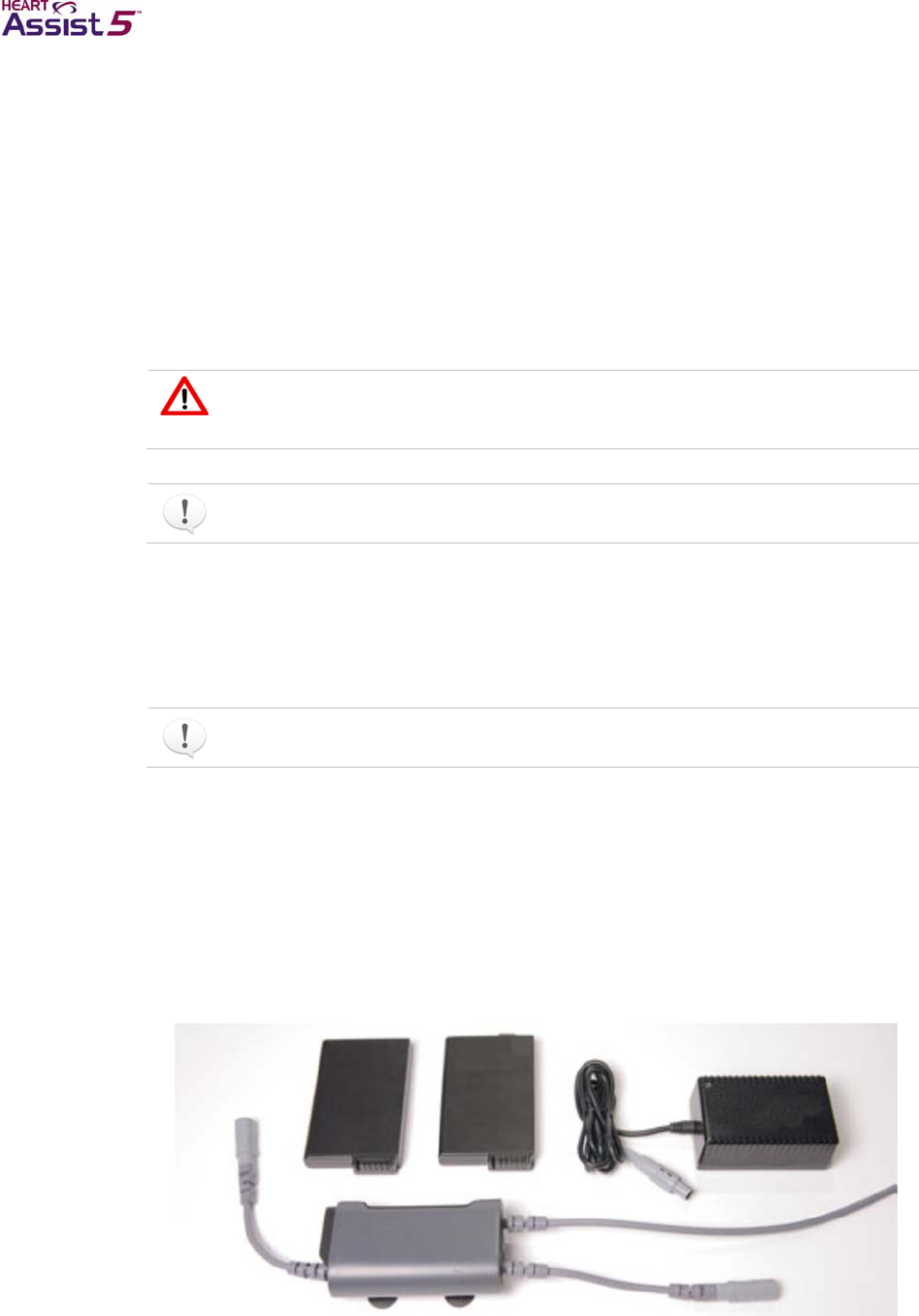
4–6 HeartAssist 5® VAD System Operator's Manual
Manual restart
If the nine attempts to automatically restart the VAD are unsuccessful, the Controller
ceases any further attempts to restart the VAD. Initiate manual restarts with the following
method:
1. Disconnect the battery pockets from any external power sources (such as the
Independent Power Supply).
2. Briefly remove both batteries from the battery pockets.
3. Re-insert one of the charged batteries into one of the battery pockets.
This action activates the restart algorithm, which triggers an additional nine automatic
restart attempts.
Only attempt to manually restart the VAD one time. If the VAD does not
successfully restart, immediately begin the procedure detailed in the next
section, “Controller replacement.”
When the pump restarts, the PUMP STOPPED emergency alarm automatically
clears.
Controller replacement
Replace the Controller only when it is absolutely clear that the existing Controller has
malfunctioned.
Read all instructions thoroughly before replacing the Controller.
Setting up the equipment
Use the following steps to replace the Controller.
1. Locate the necessary backup equipment (Figure 4-3):
Backup Controller
Independent Power Supply or at least one charged battery
Figure 4-3. Backup equipment for replacing the Controller
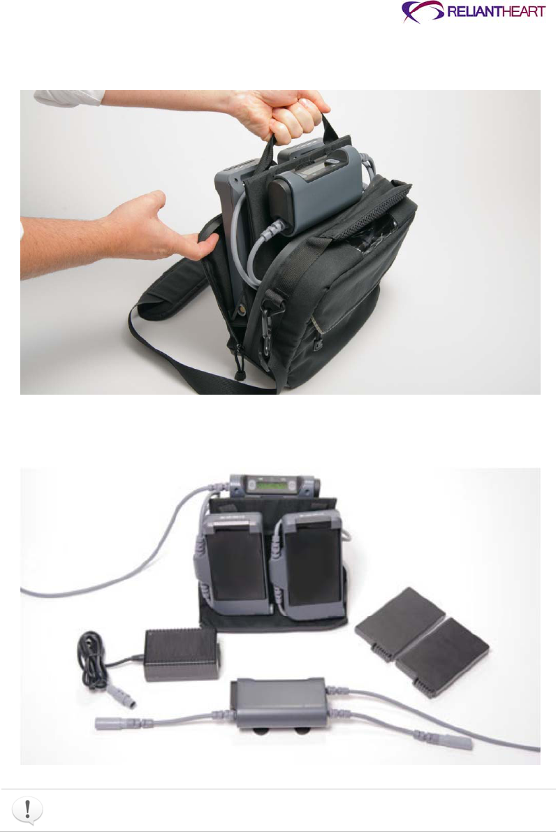
ReliantHeart Confidential – Medical Personnel and Technical Staff 4–7
2. Remove the VADPAK Insert from the VADPAK.
Figure 4-4. Removing the VADPAK Insert from the VADPAK
3. Arrange all of the components in the VADPAK Insert and all of the backup equipment
so that they are easy to access.
Figure 4-5. Arranging the components for easy access
Ensure that there is at least one charged battery or an external power source
available.
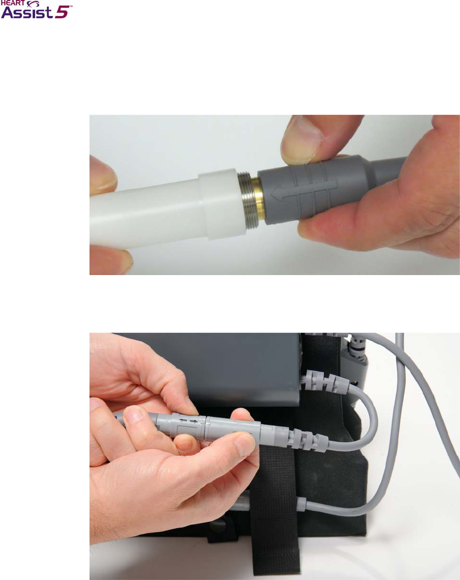
4–8 HeartAssist 5® VAD System Operator's Manual
Connecting the backup Controller
The patient must sit or recline for this procedure.
1. Unscrew the defibrillation cover, by turning it counter-clockwise, to access the
driveline connector.
Figure 4-6. Unscrewing the defibrillation cover
2. Slide the defibrillation cover back along the driveline toward the patient.
3. Disconnect one battery pocket (with charged battery) from the Controller.
Figure 4-7. Disconnecting one battery pocket from the Controller
4. Connect the battery pocket to the backup Controller.
The backup Controller begins to alarm.
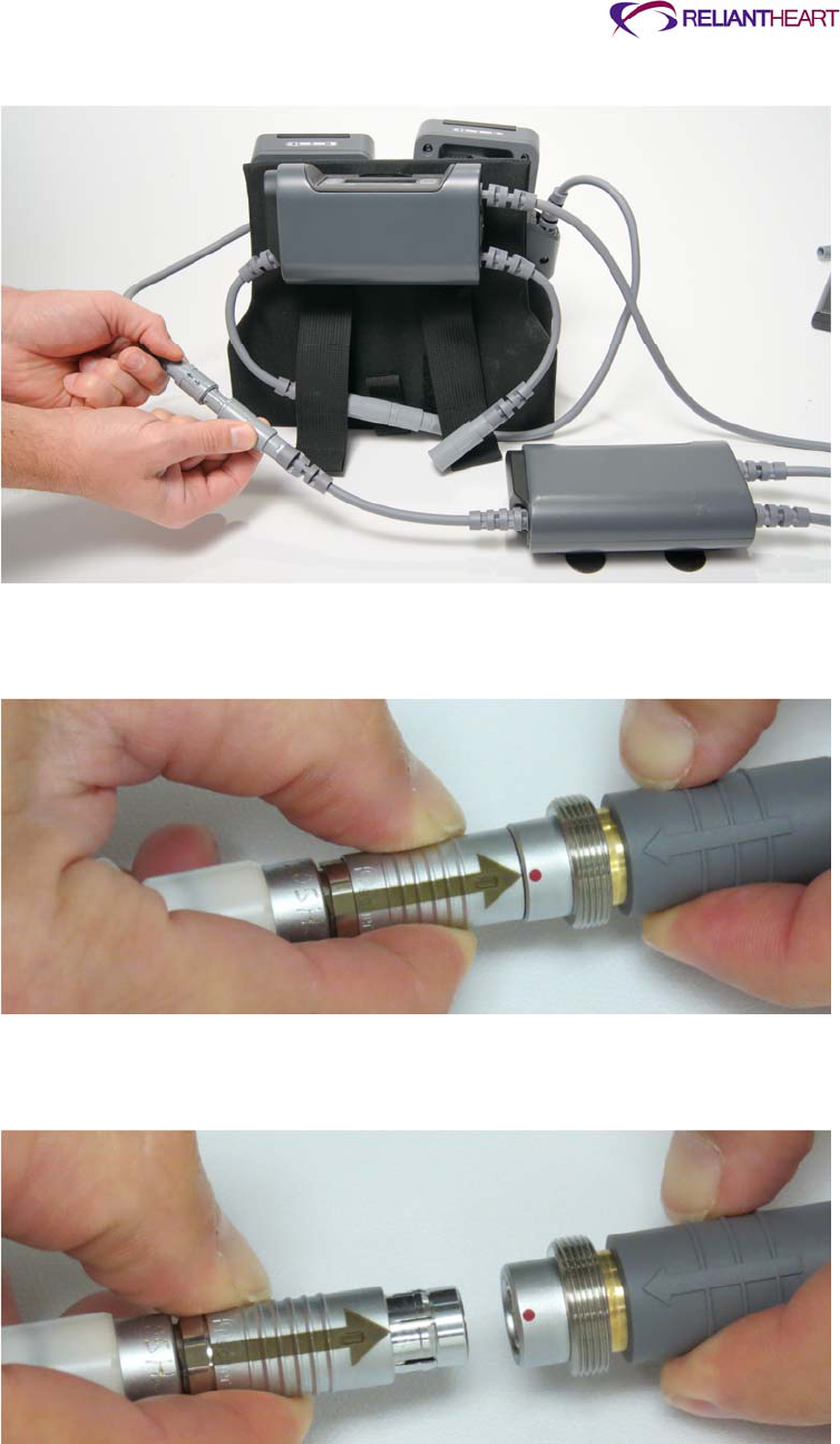
ReliantHeart Confidential – Medical Personnel and Technical Staff 4–9
Figure 4-8. Connecting the first battery pocket to the backup Controller
5. Pull the ribbed section of the driveline connector to disconnect it from the
malfunctioning Controller.
Figure 4-9. Disconnecting the percutaneous cable
6. Align the arrow on the driveline connector to the groove on the backup Controller
connector.
Figure 4-10. Aligning the driveline cable to the backup Controller
7. Firmly press the connectors together to connect the backup Controller to the VAD.
A slight click sounds as the connectors snap into place and become fully seated.
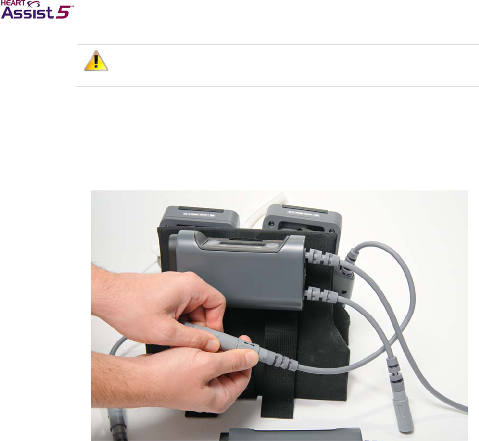
4–10 HeartAssist 5® VAD System Operator's Manual
Align the driveline connector and Controller connector properly. Forcing the
connectors with improper alignment can damage the equipment. Do not twist a
connector plug while inserting it after the connectors are aligned.
The VAD should now be running using the backup Controller.
8. Screw the defibrillation cover to the Controller cable by turning clockwise.
9. Press the Alarm Silence button.
10. Disconnect the second battery pocket from the malfunctioning Controller.
Figure 4-11. Disconnecting the second battery pocket from the Controller
11. Connect the second battery pocket to the backup Controller.
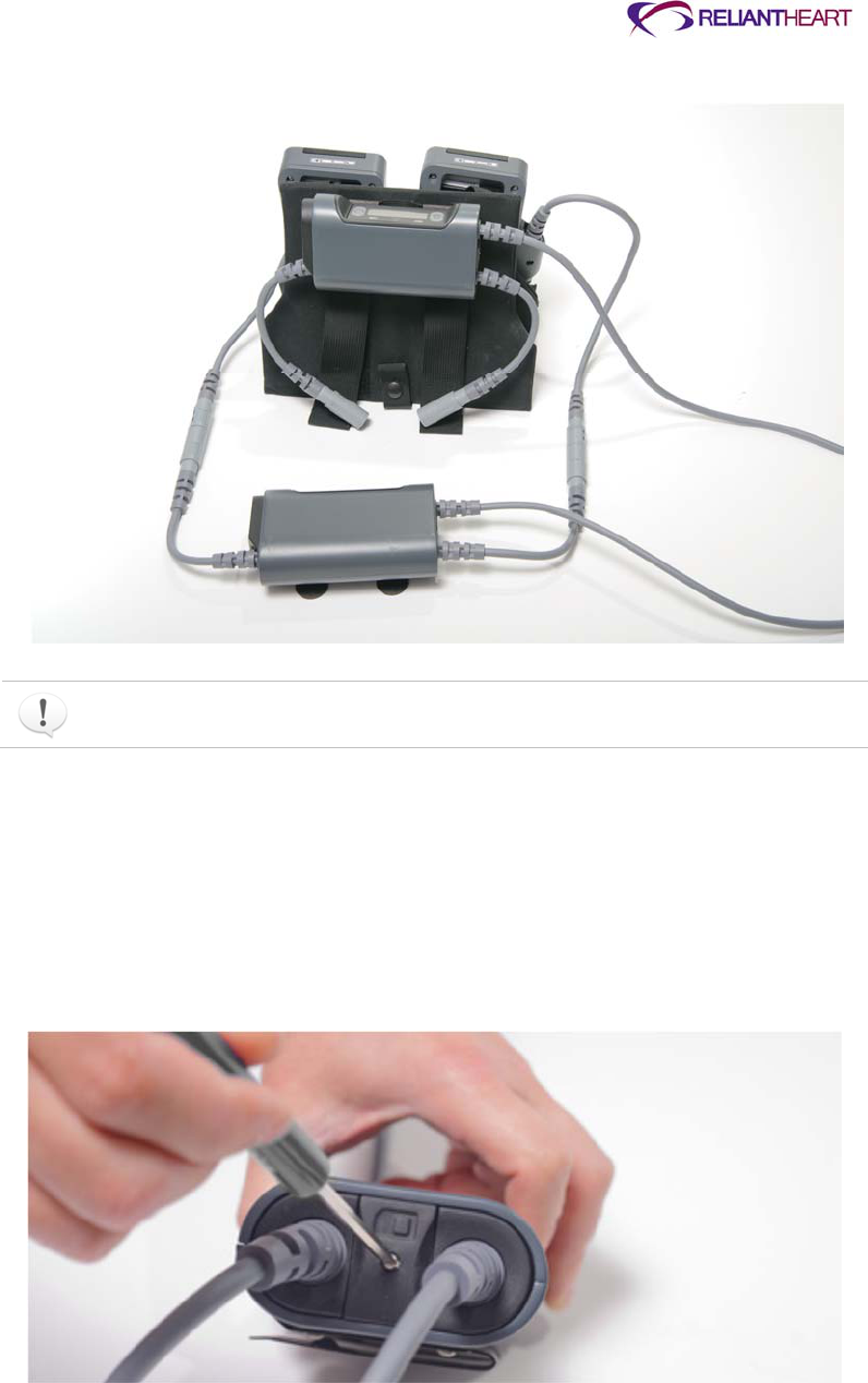
ReliantHeart Confidential – Medical Personnel and Technical Staff 4–11
Figure 4-12. Connecting the second battery pocket to the backup Controller
The malfunctioning Controller continues to alarm for approximately three minutes
after you disconnect the power. You cannot silence this alarm.
Replacing the SIM card
When you replace the Controller, you must transfer the SIM card from the malfunctioning
Controller to the backup Controller. Continue with the following steps to replace the SIM
card.
1. Locate and use the screwdriver supplied by ReliantHeart to remove the SIM card
cover located on both Controllers.
Figure 4-13. Removing the SIM card cover with the ReliantHeart screwdriver

4–12 HeartAssist 5® VAD System Operator's Manual
Figure 4-14. SIM card covers removed from both Controllers
2. Remove the SIM card from the malfunctioning Controller.
Figure 4-15. Removing the SIM card from the Controller
3. Insert the SIM card into the backup Controller.
The SIM card clicks when it is properly seated.
Figure 4-16. Inserting the SIM card into the backup Controller
4. Reattach the SIM card cover on both Controllers, and secure the cover using the
screwdriver.

ReliantHeart Confidential – Medical Personnel and Technical Staff 4–13
Figure 4-17. Replacing the SIM card cover
5. Contact ReliantHeart immediately.
The Controller replacement is now complete.
Controller safety check
ReliantHeart recommends a periodic safety check of the Controller to ensure continued
proper operation.
Perform the following steps to verify the safety of the Controller.
Testing with the batteries
Test the safety of the Controller using the batteries.
1. Verify that all three connections to the Controller are secure and undamaged.
2. Disconnect the HeartAttendant® or Independent Power Supply from the battery
pocket (if connected).
3. Verify that the percent charge of both batteries as displayed on the Controller LCD
indicates a charge level above 25%.
4. Remove battery 1 from the battery pocket.
5. Verify that the % charge of battery 1 displays a line:
—
and that the LED for battery
1 is a flashing amber light.
6. Reinstall battery 1.
7. Verify that the Controller emits three audible beeps and that the Controller LCD
displays the % charge for battery 1.
8. Remove battery 2 from the battery pocket.
9. Verify that the % charge of battery 2 displays a line:
—
and that the LED for battery
2 is a flashing amber light.
10. Reinstall battery 2.
11. Verify that the Controller emits three audible beeps and that the Controller LCD
displays the % charge for battery 2.
Testing with the HeartAttendant®
Test the safety of the Controller using the HeartAttendant®
.

4–14 HeartAssist 5® VAD System Operator's Manual
1. Connect the HeartAttendant® to the external port of the VADPAK.
See “Connecting the Controller to the HeartAttendant®” on page 5-4.
2. Perform the following tests from the SETUP screen and record any anomalies:
Test LCD Messages
Test LED Annunciators
Test Audible Annunciator
Test LCD Display and Backlight
See “Running Controller tests” on page 5-14.
3. Store a screen shot from the DATA screen, entering the patient’s current, flow,
speed, and power values into the comment box.
See “Obtaining screenshots” on page 5-26.
4. From the SETUP screen, sync the HeartAttendant® time. See “SYNC TIME button”
on page 5-16.
5. Press the ALARM HISTORY button to review a log of previous alarms.
See “ALARM HISTORY button and Alarm window” on page 5-10.
6. Verify that the alarm parameters are appropriate for the patient.
7. If the Controller has displayed a PUMP STOPPED alarm since the last Controller
check, download both the First Event and Last Event from the EVENTS screen.
See “Retrieving data segments” on page 5-21.
If the Controller is functioning improperly during the safety check, replace the
Controller using the procedure defined in “Controller replacement” on page 4-6,
repeat the steps in “Controller safety check,” and contact ReliantHeart immediately.
Battery pockets
The battery pockets securely hold the lithium ion batteries that power the HeartAssist 5®
VAD System.

ReliantHeart Confidential – Medical Personnel and Technical Staff 4–15
Figure 4-18. Battery pocket
Each battery pocket is comprised of the following components:
Green and amber LED indicators that indicate the status of the battery.
External interface port that facilitates convenient connection to external power sources
(such as the Independent Power Supply).
Metal belt clip that allows you to rotate the battery pocket 360° for comfortable
positioning and for attaching to a belt or the VADPAK Insert for easy mobility.
Retention clip that safely secures the battery in the battery pocket while providing easy
access for battery insertion and removal.

4–16 HeartAssist 5® VAD System Operator's Manual
VADPAK
The VADPAK is an ergonomic storage system that allows the patient to carry the
Controller, battery pockets, and batteries (Figure 4-19).
Figure 4-19. VADPAK
VADPAK components
The VADPAK is comprised of three components:
A removable VADPAK Insert that organizes the Controller, battery pockets, batteries,
and cables.
A protective pouch with a padded shoulder strap.
An emergency information card with appropriate contact information.
Setting up the VADPAK Insert
The VADPAK Insert is a reinforced fabric organizer for the Controller, battery pockets,
batteries, and associated cables. It is designed to allow easy management and transport
of the HeartAssist 5® VAD System during everyday use.

ReliantHeart Confidential – Medical Personnel and Technical Staff 4–17
Figure 4-20. VADPAK Insert
Use the following steps to set up the VADPAK insert.
1. Place the VADPAK Insert on a secure surface near the percutaneous cable exit site.
2. Slide the battery pockets side by side onto the matching fabric straps on the
VADPAK Insert using the battery pocket belt clips.
Figure 4-21. Securing the battery pockets in the VADPAK Insert
3. Slide the Controller onto the fabric strap using the Controller belt clip so that the
Controller display is facing upward.
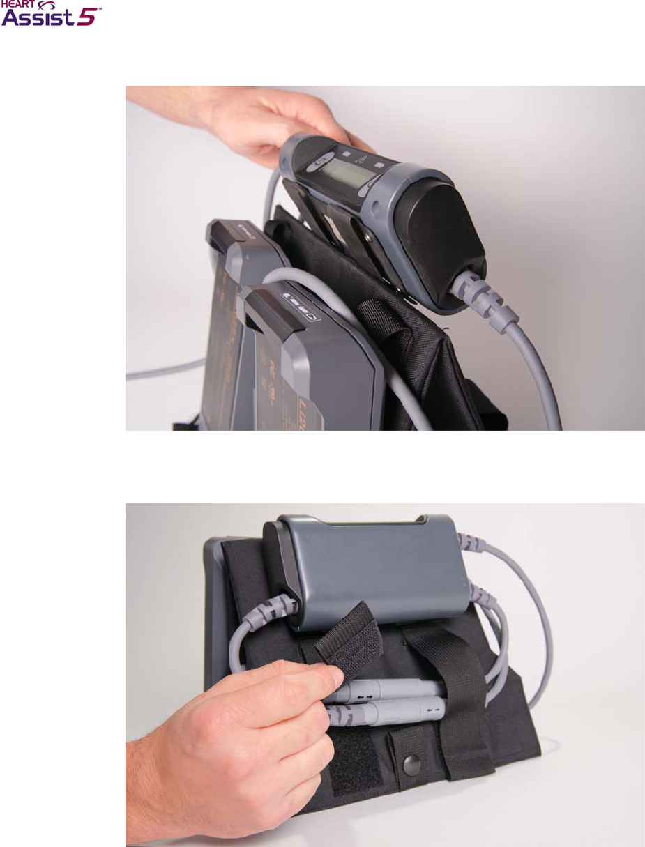
4–18 HeartAssist 5® VAD System Operator's Manual
Figure 4-22. Securing the Controller into the VADPAK Insert with the
Controller display facing upward
4. Secure the battery connectors and cables below the Controller using the Velcro®
straps.
Figure 4-23. Securing the battery connectors in the VADPAK Insert
5. Grasp the VADPAK Insert by the handle, and place it in the VADPAK with the
Controller display visible in the clear window of the VADPAK.
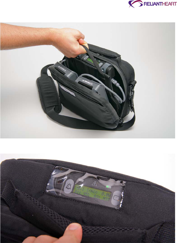
ReliantHeart Confidential – Medical Personnel and Technical Staff 4–19
Figure 4-24. Placing the VADPAK Insert in the VADPAK
Figure 4-25. Viewing the Controller in the clear window of the VADPAK
6. Route the driveline cable to the opening below the end of the zipper in the VADPAK.

4–20 HeartAssist 5® VAD System Operator's Manual
Figure 4-26. Routing the driveline cable in the VADPAK
7. Zip the VADPAK all the way to the end of the zipper to prevent the VADPAK Insert
from falling out of the VADPAK.
Figure 4-27. Zipping up the VADPAK completely
The VADPAK is now ready to carry using the handle or the shoulder strap.
Patients can easily remove the VADPAK Insert to aid in replacing batteries or
connecting to external power sources.
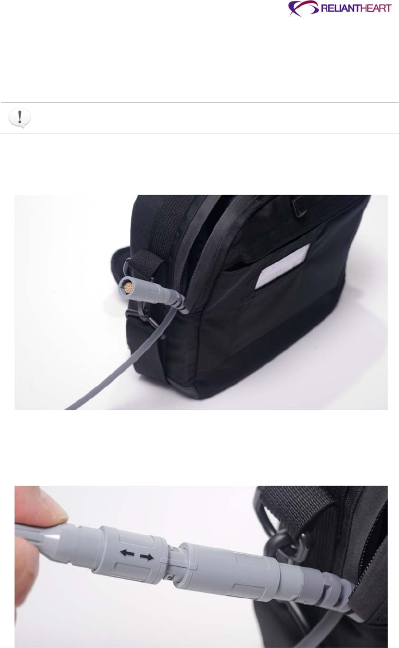
ReliantHeart Confidential – Medical Personnel and Technical Staff 4–21
Connecting to external power
Use the following instructions to connect the Controller to external power sources using
the battery pocket’s external power connector. These steps are performed while the
Controller is in the VADPAK Insert.
These instructions apply to all external power supply sources. All external power
sources share identical connectors.
1. Open the VADPAK to expose the external power connector on the bottom of the
battery pocket.
Figure 4-28. Exposing the battery pocket external power connector
2. Visually align the arrow on the power source connector (such as the Independent
Power Supply) with the square on the battery pocket external power connector on the
bottom of the battery pocket.
Figure 4-29. Aligning the arrow on the power source connector with the
square on the battery pocket external power connector
3. Once the arrow and the square are aligned, firmly push the power source connector
straight into the battery pocket external power connector.

4–22 HeartAssist 5® VAD System Operator's Manual
A slight click sounds, and the connectors snap into place as they become fully
seated.
4. When you are connected to a single external power source, the following indications
verify your external power connection:
The Controller emits three audible beeps.
The Controller screen and the connected battery pocket both display a solid green
light.
The external power indicator (a plug symbol) displays on the Controller screen in
place of the charge time remaining for the connected battery pocket.
5. Route the connector cable and the percutaneous cable to the opening below the end
of the zipper.
Figure 4-30. Routing the cables in the VADPAK
6. Zip the VADPAK all the way to the end of the zipper to prevent the VADPAK Insert
from falling out of the VADPAK.
See Figure 4-27, “Zipping up the VADPAK completely” on page 4-20.
The VADPAK is now ready to carry using the handle or the shoulder strap.
Power supply
While you are away from home, the HeartAssist 5® VAD System can draw power from a
variety of sources including batteries, the Independent Power Supply.
Batteries
The batteries that power the VAD are lithium ion smart batteries. Each battery powers the
VAD for approximately 4.5 – 7.5 hours, providing a combined battery time of
approximately 9 – 15 hours.
Figure 4-31 displays an example of a HeartAssist 5® VAD battery.
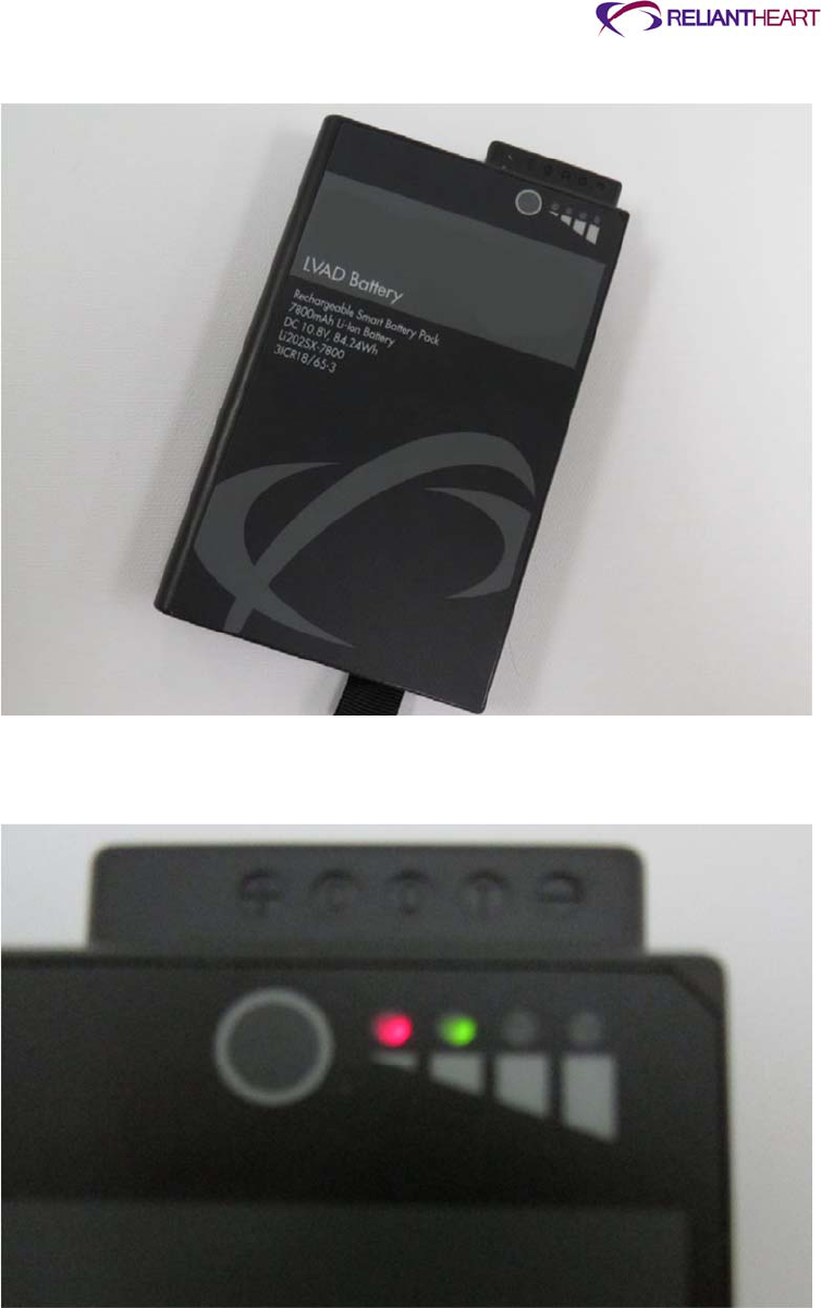
ReliantHeart Confidential – Medical Personnel and Technical Staff 4–23
Figure 4-31. HeartAssist 5® VAD battery
Figure 4-32 displays an example of the charge level indicators on a battery.
Figure 4-32. Battery charge level indicators
Each battery contains an integrated charge level indicator display consisting of four LEDs
on the face of the battery. The LEDs represent the maximum charge level the battery
contains in 25% increments. Table 4-1 describes the LED battery charge level indicators.
To activate the charge level indicator display on the battery, press the circular Check
button above the indicator LEDs.

4–24 HeartAssist 5® VAD System Operator's Manual
Table 4-1. Battery charge level LED indicators
Charge level indicator LEDs on battery Percent charged
4 75% – 100%
3 50% – 75%
2 25% – 50%
1 red 10% – 25%
1 flashing red Below 10%
The battery in Figure 4-32 is 25% – 50% charged.
Battery time can vary from patient to patient depending on the set VAD speed.
Connecting a battery pocket to the Controller
The Controller connects to the battery pockets with connectors that are on the end of
cables extending from the units. The Controller has two connectors that connect to the
battery pockets, and these connectors are designed for ease of use.
Use the following steps to connect the battery pocket connectors to the Controller
connectors.
1. Visually align the arrow on the battery pocket connector with the square on the
Controller connector.
Figure 4-33. Aligning the arrow on the battery pocket connector with the
square on the Controller connector
2. After you align the arrow and the square, firmly push the battery pocket connector
straight into the Controller connector.
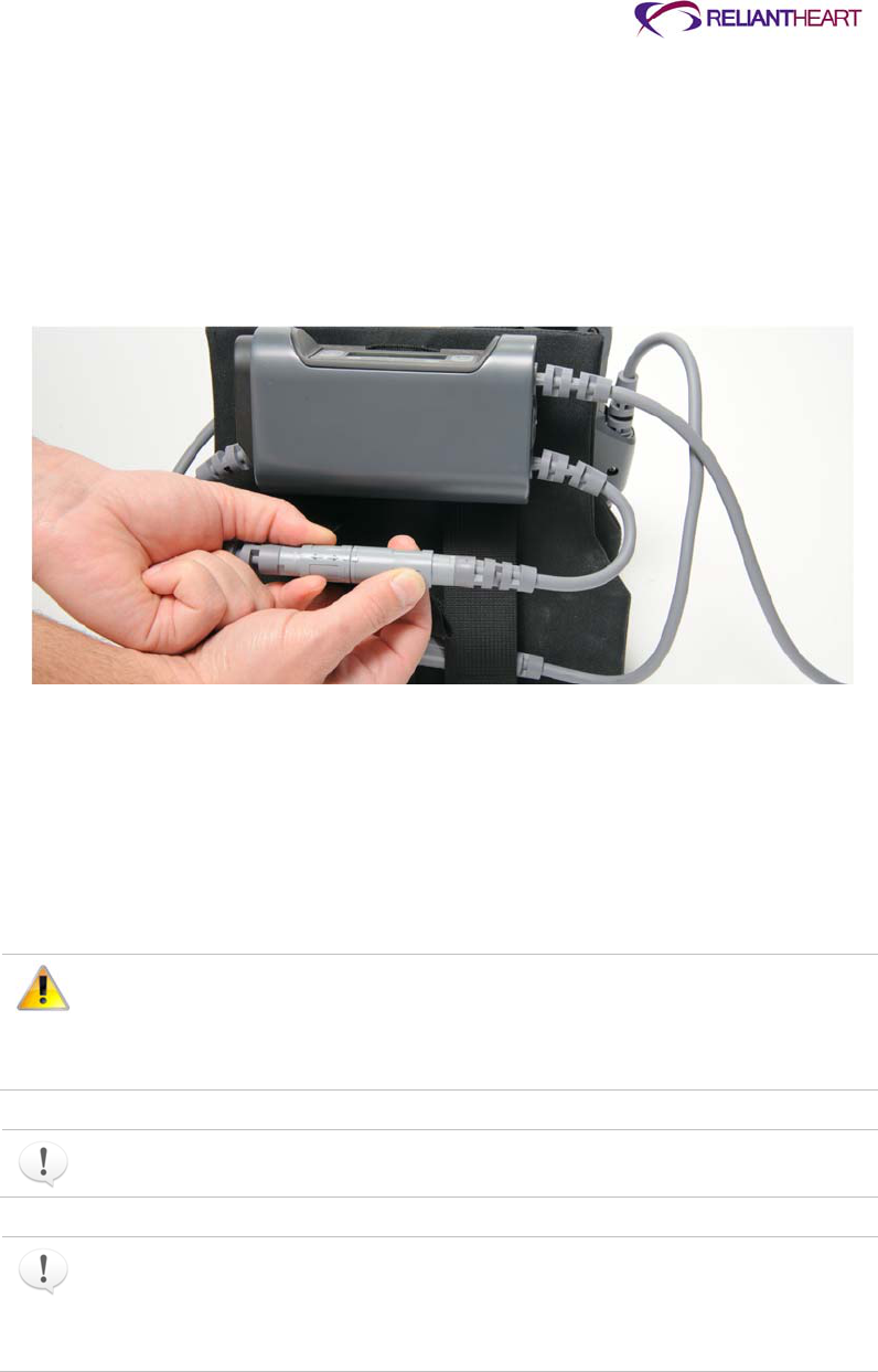
ReliantHeart Confidential – Medical Personnel and Technical Staff 4–25
A slight click sounds, and the connectors snap into place as they become fully
seated.
The Controller emits three audible beeps, and the Controller LCD displays the
percent charge for the connected battery pocket.
If the connected battery is either discharged or expired, the battery indicator LED
for that battery pocket flashes an amber light, and the Controller emits audible
alarms and displays visual alarms.
Figure 4-34. Batteries connected to the Controller
Alternately, if you cannot visually align the arrow and the square, use the following
steps:
a. Gently insert the battery pocket connector 2mm (1/16 of an inch).
b. With very little pressure applied, rotate the battery pocket connector until it
mates with the Controller connector and no longer rotates freely.
c. Firmly push the battery pocket connector straight into the Controller connector
until they are fully seated.
Align all connectors properly. Forcing connectors without proper alignment
can damage the equipment. Do not try to force a power source connector into
the battery pocket external power connector. When removing a cable, hold the
connector, and pull it out. Do not twist the connectors while inserting them or
removing them after the connectors are aligned.
Both battery pocket connectors are identical. The Controller automatically switches
to draw power from the appropriate battery.
When an external power source (such as the Independent Power Supply) is
connected to the battery pocket external power connector, the power source
bypasses the battery in the battery pocket and supplies power directly to the
Controller port. The Controller displays the external power indicator (a plug symbol)
in place of the battery charge percentage.
4–26 HeartAssist 5® VAD System Operator's Manual
Interpreting Controller battery indicators
The battery indicators on the top corners of the Controller front panel indicate three
different conditions for each battery. See Figure 4-2, “Controller front panel,” on page 4-3
for an example of the battery indicators.
Table 4-2. Controller battery indicator descriptions
Indicator condition Meaning
Solid green This battery pocket is connected to external power, and the
Controller is using external power from this battery pocket to run
the VAD.
Flashing amber
a
This battery pocket contains either a discharged, an expired, or no
battery.
Off This battery pocket contains a battery with an adequate charge
level, which is correctly installed and is in use or is ready for use.
a Flashing amber lights indicate batteries that should be changed. Always change batteries
with flashing amber lights before batteries with no lights.
The Controller always uses the battery with the lower charge and continues to use
the battery down to a 25% charge level, thus preserving the battery with the highest
charge for later use.
The patient must periodically (every two to three hours) visually inspect the
front panel of the Controller to verify battery status in case of a diagnostic
audible alarm failure.
Changing a battery
Use the following steps to change a battery.
1. Determine which battery to change by selecting the one with the lower charge using
one of the following methods:
Use the LCD display on the Controller.
See Figure B-1, “Standard message screen 1: battery status,” on page B-2.
Use the battery indicator LED on the Controller or battery pockets.
See Table 4-2, “Controller battery indicator descriptions,” on page 4-26.
Press the battery charge level indicator Check button on each battery to determine
its charge level.
Batteries with adequate charge levels have no indicator lights on the Controller
and battery pockets. Batteries with flashing amber indicator lights on the Controller
and battery pockets have less than a 25% charge level and should be changed
first. See Table 4-2, “Controller battery indicator descriptions,” on page 4-26 for
other battery conditions and Figure 4-32, “Battery charge level indicators,” on page
4-23.
2. Ensure that the remaining battery indicates adequate charge on the Controller LCD
display.
3. Remove the battery with the lower charge from the battery pocket.
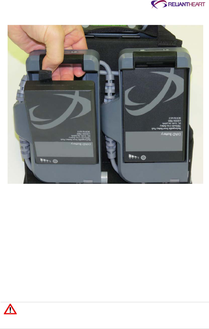
ReliantHeart Confidential – Medical Personnel and Technical Staff 4–27
Figure 4-35. Removing the battery from the battery pocket
4. Verify that the battery to be inserted is fully charged by pressing the battery level
charge indicator Check button on the battery itself.
See Table 4-1, “Battery charge level LED indicators,” on page 4-23. All four LEDs on
the battery should illuminate, indicating a charge between 75% and 100%.
5. Align the connector on the battery with the receptacle in the pocket, and insert the
charged battery into the pocket until it clicks.
The Controller emits three audible beeps, and the Controller LCD displays the
percent charge for the connected battery. Any flashing amber indicator lights turn
off.
The BATTERY DISCHARGED and BATTERY DISCONNECTED alarms clear
automatically.
6. Verify the percent charge of the replaced battery on the Controller LCD display.
See the following section, “Verifying battery charge status.”
Only remove one battery at a time from the battery pockets. Removing both
batteries simultaneously causes the VAD to stop (unless you are in tethered
mode). The batteries must be reconnected as quickly as possible to resume
VAD function.

4–28 HeartAssist 5® VAD System Operator's Manual
Do not handle batteries by the connector pins. A strong static discharge can
cause the charge level indicator to temporarily malfunction. If the charge level
indictor ceases to function, place the battery into a ReliantHeart charger, and
recharge the battery.
Verifying battery charge status
Use one of the following methods to check the charge status of either battery:
Look at the Controller LCD display.
Press the charge level indicator button on the battery, adjacent to the battery charge
indicator LEDs.
See Table 4-1, “Battery charge level LED indicators,” on page 4-23 for a description of
the LED meanings.
Even when they are connected to an external power source (such as the
Independent Power Supply or the HeartAttendant®), the batteries located
inside the battery pockets drain and lose charge over time. Verify that the two
batteries in the battery pockets have sufficient charge levels prior to
disconnecting the system from an external power source.
Verifying battery capacity
Battery capacity number refers to the total power available from the battery when fully
charged. As the battery ages with normal use, this number decreases.
Verify the total battery capacity using standard message screen 6: battery capacity on the
Controller. (See Figure B-6 on page B-3.) The screen displays the maximum battery
capacity in milliamp hours. Once a battery displays a total capacity of 6000 milliamp
hours or less, contact ReliantHeart for a replacement battery.
Obtain replacement batteries from ReliantHeart after the battery capacity
indicates less than 6,000 milliamp hours. Only use batteries supplied by
ReliantHeart.
A battery that displays less than 6000 milliamp hours is still a good battery; however,
the battery might not provide as much total support time as a new battery.
LVAD Battery Charger
Figure 4-36 displays the LVAD Battery Charger. It charges and reconditions batteries
used with the HeartAssist 5® VAD System. Table 4-3, “LVAD Battery Charger status
lights description,” on page 4-30 describes the charge indicator lights.
With batteries, the LVAD Battery Charger weighs approximately 3.6 pounds (1.7 kg). It is
enclosed in a durable case that is both moisture and flame resistant.
Figure 4-36. LVAD Battery Charger

ReliantHeart Confidential – Medical Personnel and Technical Staff 4–29
Certain battery chargers can only charge or recondition one battery at a time. This is
denoted by the recondition arrow solely indicating the left bay as the recondition slot.
Please verify the proper model before following the steps for charging or conditioning
of batteries.
Connecting to a power source
Use the following steps to connect the LVAD Battery Charger to wall power.
1. Plug the main power cord into the AC power input on the LVAD Battery Charger.
2. Connect the plug to an AC power source.
The power adapter is universal for both domestic and European AC input voltages.
Charging batteries
Use the following steps to charge the batteries.
1. Identify the appropriate model, before attempting reconditioning or charging.
2. Inspect the connector end of each battery to ensure that it is clean.
3. Insert one or two batteries into the two bays of the LVAD Battery Charger.
4. Allow 5 – 10 seconds for the LVAD Battery Charger to recognize the battery.
Depending on model type, the charger can charge one or two batteries
simultaneously. The charging process can take up to 3.5 hours per battery. If the
battery status light below the battery bay flashes green, the battery is charging. If a
battery status light flashes red, the battery charger is in error mode.
If the battery status lights flash a red color, you must remove both batteries and
unplug the power cord. Wait 15 seconds, reinsert the batteries, and reconnect the
power cord. If the batteries are warm, wait for 30 minutes before reinserting them.
4–30 HeartAssist 5® VAD System Operator's Manual
Always check batteries by pushing the charge level indicator button on the battery to
verify charge level when removing batteries from the LVAD Battery Charger.
Using a battery charger that is not supplied by ReliantHeart could result with
batteries that could be charged inappropriately causing an over or under charged
condition resulting in discharge times that are noticeably shorter than intended.
Table 4-3 describes the LVAD Battery Charger status lights.
Table 4-3. LVAD Battery Charger status lights description
Light status Battery status
Off No battery
Green flashing Fast charging
Green solid Fully charged
Amber flashing Reconditioning
Amber and green Reconditioned
Amber solid Standby or Suspend
Red flashing Error
Reconditioning batteries
To maintain the accuracy of the battery indicators, batteries must occasionally run
through a recondition cycle. Use the following steps to recondition batteries.
1. Place the battery into the left bay, for chargers with only one recondition slot. Use
either slot with the charger capable of reconditioning in either position.
2. Press the Recondition button on the front label of the charger, directly below the
battery slot.
The reconditioning process can take up to 9 hours.
Connection other than indicated can result in permanent damage to the LVAD
Battery Charger.
Avoid placing or operating the LVAD Battery Charger in areas or near
appliances that expose it to temperatures outside of the operating range of the
device, which is 0 °C (32 °F) to 50 °C (122 °F).
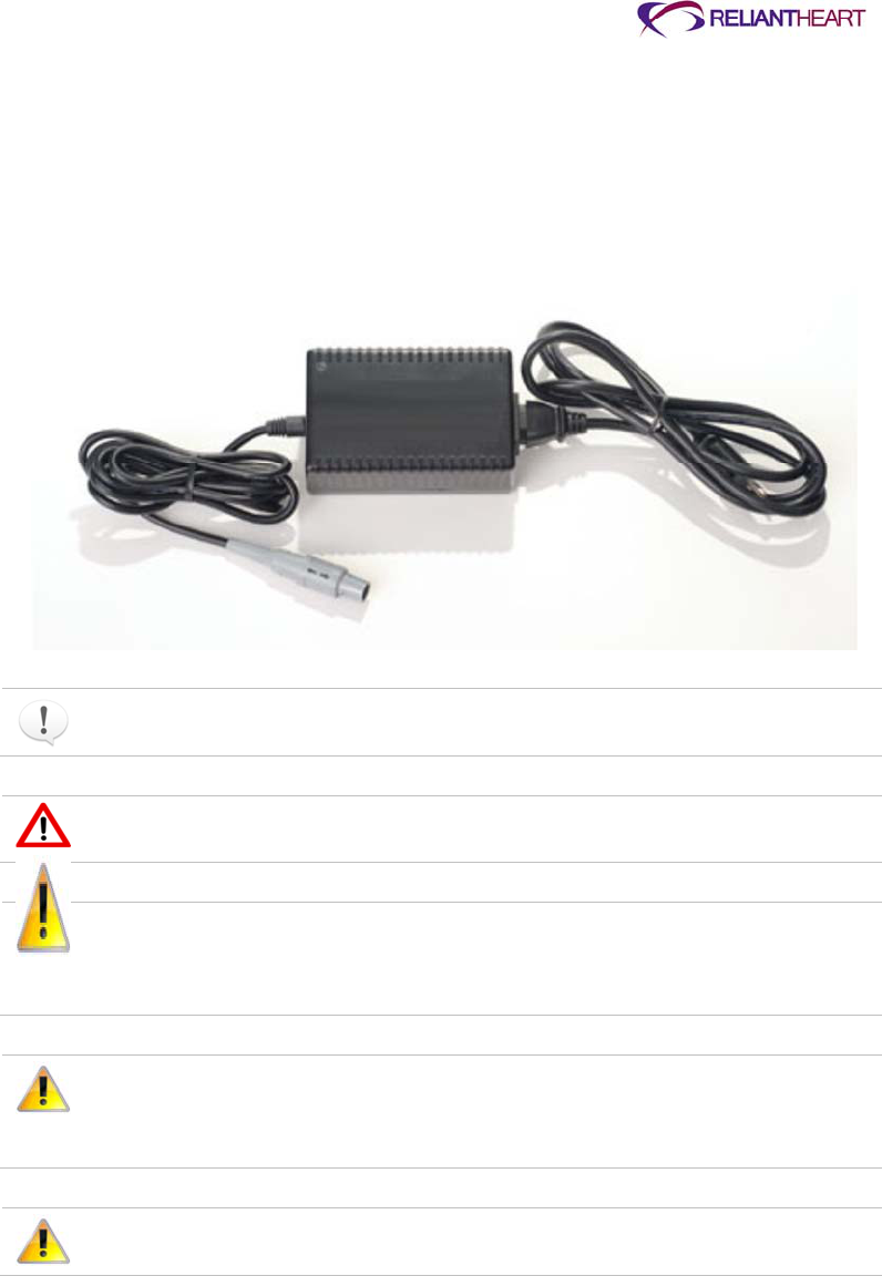
ReliantHeart Confidential – Medical Personnel and Technical Staff 4–31
Independent Power Supply
The Independent Power Supply is a portable power supply that supplies AC power to the
VAD via the battery pocket external power connector.
Use this power supply as a backup power source in conjunction with the two battery
pockets containing charged batteries.
Figure 4-37. Independent Power Supply
The Independent Power Supply is for use only by patients who are implanted with
the HeartAssist 5® VAD System.
Do not store or use the Independent Power Supply near water or any liquid (for
example, in the bathroom or kitchen) due to the risk of electrical shock.
The Independent Power Supply contains no user-serviceable parts. Do not
open the back cover of the Independent Power Supply. Only qualified
ReliantHeart personnel can service this equipment. If service is required,
contact ReliantHeart.
Avoid placing or operating the Independent Power Supply in areas or near
appliances that expose it to temperatures outside the operating range of the
device, which is 0 °C (32 °F) to 40 °C (104 °F) or where relative humidity is
noncondensing, less than 10% Rh or greater than 75% Rh.
Do not trip over the power cord. Instruct persons in the area to prevent
tripping.

4–32 HeartAssist 5® VAD System Operator's Manual
Connecting the Independent Power Supply to the Controller
Figure 4-38 and the following instructions serve as a guide for connecting the
Independent Power Supply to an AC power source and to the Controller.
Figure 4-38. Independent Power Supply connection diagram
Use the following instructions to connect the Independent Power Supply to the Controller.
1. Plug the power cord of the Independent Power Supply into the wall plug. See “1” in
Figure 4-38.
2. Plug the power cord into the Independent Power Supply. See “2” in Figure 4-38.
3. Plug the Independent Power Supply connector into the battery pocket external power
connector (which is already connected to the Controller; see “Connecting a battery
pocket to the Controller” on page 4-24). See “3” in Figure 4-38.
If all connections are secure, and the components are working properly, the Controller
emits three audible beeps, the Controller front panel displays the external power indicator
(a plug symbol), and the battery indicator LED on the Controller’s front panel displays a
solid green light for the connected battery pocket.
When you are using the Independent Power Supply, the Controller uses power from the
grounded AC wall outlet. The Controller can also receive backup power from the two
charged batteries in the battery pockets if the wall outlet fails. If a power failure occurs,
the Controller sounds an audible alarm, notifying you that it is using backup battery
power.
Use the Independent Power Supply only with a properly grounded plug. To
reduce the risk of electrical shock, plug this equipment into grounded outlets
only. If your power outlets are not grounded, an electrician must install
grounded outlets before you can use this equipment outside of the hospital.

ReliantHeart Confidential – Medical Personnel and Technical Staff 5–1
Chapter 5
In this chapter
Overview ....................................................................................................................................... 5-3
Powering on the HeartAttendant® ................................................................................... 5-3
Connecting the Controller to the HeartAttendant® .......................................................... 5-4
Description of screens ................................................................................................................... 5-6
Status Display pane ......................................................................................................... 5-7
Display Select buttons pane ............................................................................................ 5-7
PATIENT screen ........................................................................................................................... 5-7
Managing alarms and accessing sleep mode .................................................................. 5-8
Viewing VAD flow in real time ........................................................................................ 5-12
Viewing VAD status........................................................................................................ 5-12
Viewing the patient ID .................................................................................................... 5-13
SETUP screen ............................................................................................................................ 5-13
Running Controller tests ................................................................................................ 5-14
Viewing the Controller communication status and ID and setting the language,
date, and time .......................................................................................................... 5-14
Deactivating the flow sensor .......................................................................................... 5-16
Presetting VAD speed .................................................................................................... 5-16
Setting alarm parameter thresholds ............................................................................... 5-16
Using the Setup Action buttons ...................................................................................... 5-17
PUMP screen .............................................................................................................................. 5-18
Starting and stopping the VAD ....................................................................................... 5-18
Viewing the pump status and adjusting the VAD speed ................................................ 5-19
Viewing the flow waveform graph .................................................................................. 5-20
EVENTS screen .......................................................................................................................... 5-20
Viewing event data ......................................................................................................... 5-21
Retrieving data segments .............................................................................................. 5-21
Inputting comments with event memory data ................................................................ 5-22
Changing patient directories .......................................................................................... 5-23
Loading previously saved event files ............................................................................. 5-23
DATA screen ............................................................................................................................... 5-23
Exporting patient data .................................................................................................... 5-24
Displaying and entering comments for currently displayed data ................................... 5-25
Obtaining screenshots ................................................................................................... 5-26
Retrieving screenshots .................................................................................................. 5-26
Cleaning and maintenance ......................................................................................................... 5-27
Cleaning the HeartAttendant® ....................................................................................... 5-27

5–2 HeartAssist 5® VAD System Operator’s Manual
Maintaining the HeartAttendant® ................................................................................... 5-27
Transporting the HeartAttendant® .............................................................................................. 5-27
Hazards ....................................................................................................................................... 5-27
Grounding the HeartAttendant® .................................................................................... 5-27
Verifying local mains voltage ......................................................................................... 5-28
Replacing fuses .............................................................................................................. 5-28
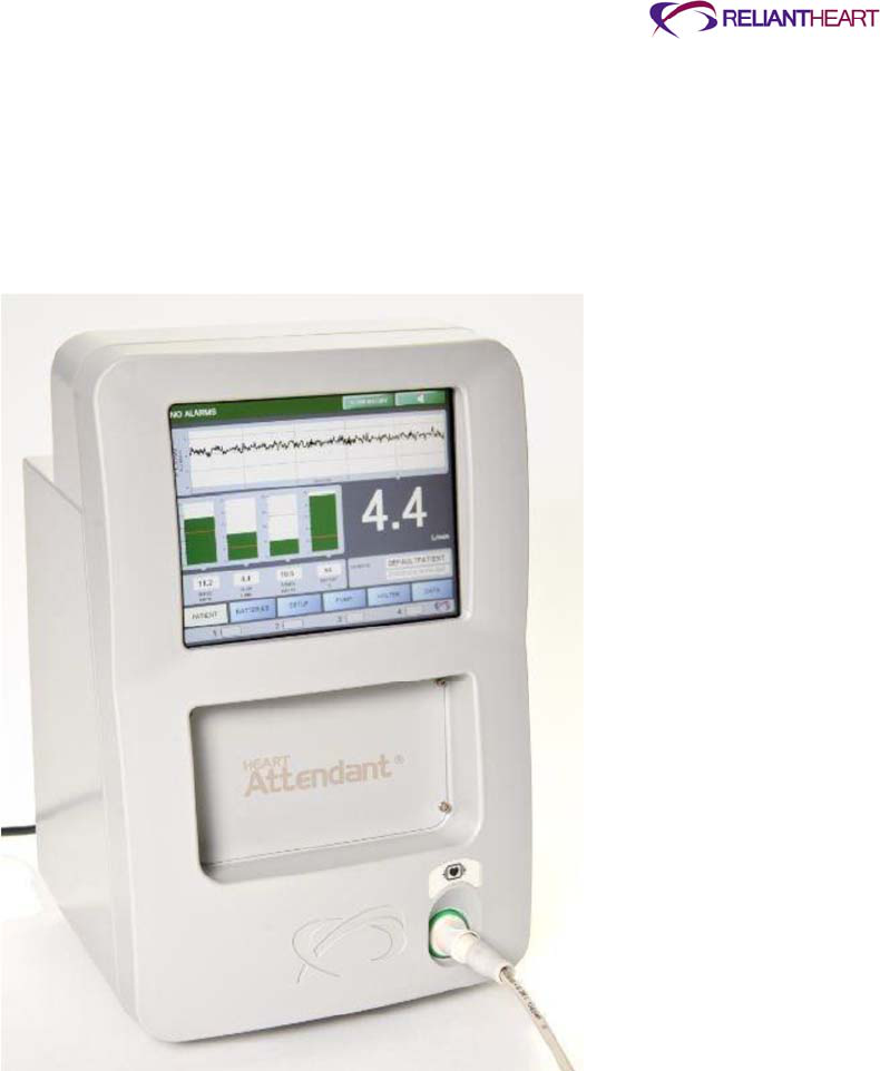
ReliantHeart Confidential – Medical Personnel and Technical Staff 5–3
Overview
The HeartAttendant® powers the VAD and the Controller. It is the means of setting the
VAD operating parameters and communicating with the Controller, and it acts as the
primary source of power during implant. The HeartAttendant® also acquires and stores
real-time performance and historical performance data (event memory).
Figure 5-1. The HeartAttendant® console
Powering on the HeartAttendant®
Use the following steps to power on the HeartAttendant®.
1. Verify the setting of the power inlet module to the correct AC power setting for the
specific country.
2. Verify or plug the appropriate power cord into the back of the HeartAttendant®.
3. Plug the power cord into the wall power source.
After the HeartAttendant® is plugged in to the wall power source, it is ready to power
the VAD, even though the boot process might still be underway.

5–4 HeartAssist 5® VAD System Operator’s Manual
When the HeartAttendant® receives a command, it makes several attempts to
communicate with the Controller. If the Controller is disconnected from the
HeartAttendant® when the HeartAttendant® receives commands the
HeartAttendant® buffers the commands for up to one minute before the it
ceases its attempts to execute the commands, and then it displays the word
DISCONNECTED on the HeartAttendant® SETUP screen in the Controller box.
Initiating HeartAttendant® commands immediately prior to connecting a
Controller can produce unexpected results.
When connecting the Controller to the HeartAttendant®, ensure that AC power
is available or that the battery pockets contain charged batteries.
Connecting the Controller to the HeartAttendant®
After the HeartAttendant® is powered on, use the following instructions to connect the
Controller to the HeartAttendant® using the battery pocket’s external power receptacle.
Perform these steps while the Controller is in the VADPAK Insert. (See “Setting up the
VADPAK Insert” on page 4-16.)
1. Connect the HeartAttendant® connector cable to the port on the HeartAttendant®.
Figure 5-2. Connecting the HeartAttendant® connector cable to the port on
the HeartAttendant®
2. Open the VADPAK to expose the battery pocket external power connector on the
bottom of the battery pocket.
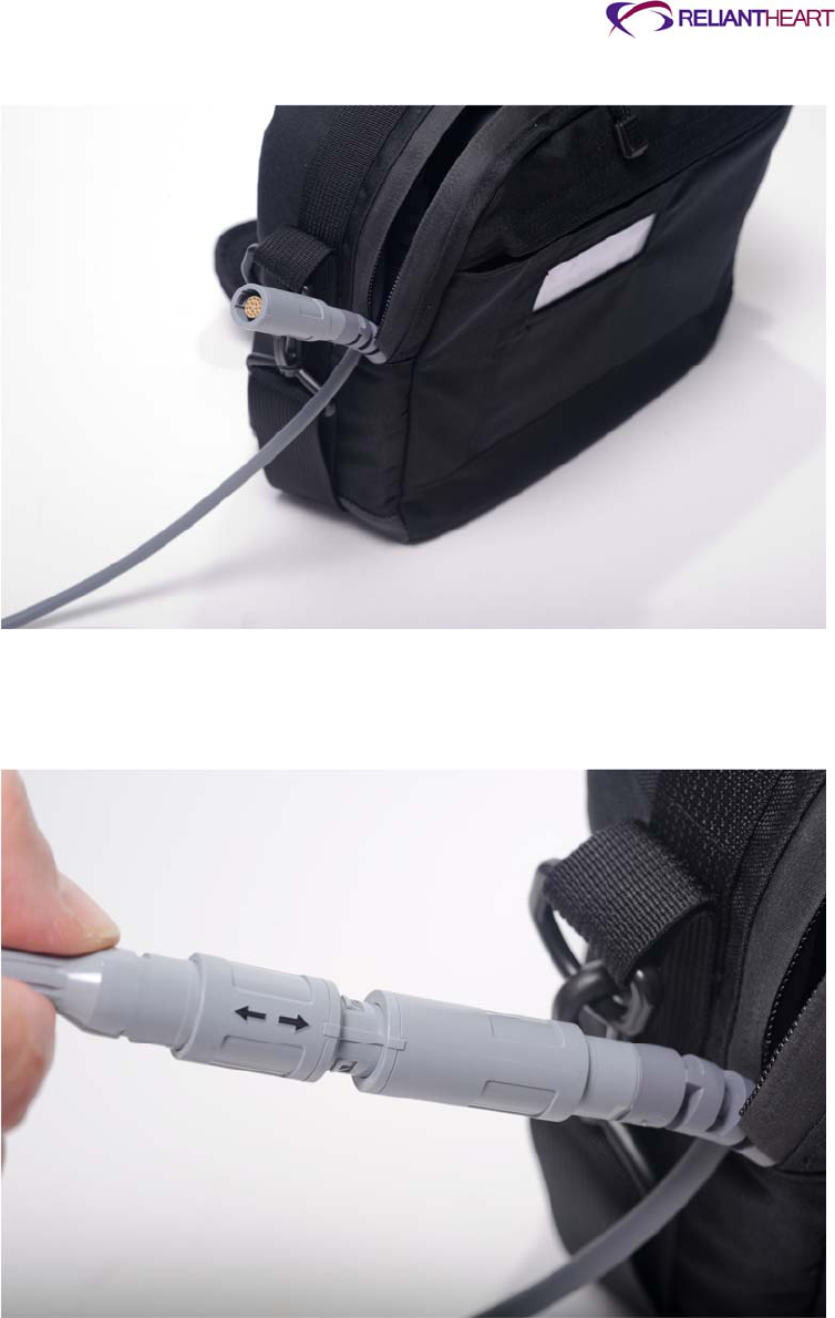
ReliantHeart Confidential – Medical Personnel and Technical Staff 5–5
Figure 5-3. Exposing the battery pocket external power connector
3. Visually align the arrow on the HeartAttendant® connecter with the square on the
battery pocket external power connector.
Figure 5-4. Aligning the arrow on the HeartAttendant® connector with the
square on the battery pocket external power connector
4. After you align the arrow and the square, firmly push the HeartAttendant® connector
straight into the battery pocket external power connector. A slight click sounds, and
the connectors snap into place and becomes fully seated.
5. Verify the external power connection with the following indications:
The Controller emits three audible beeps.

5–6 HeartAssist 5® VAD System Operator’s Manual
The Controller screen and the connected battery pocket both display a solid green
light.
The external power indicator (a plug symbol) displays as the battery percentage
for the connected battery pocket.
6. Route both cables to the opening below the end of the zipper in the VADPAK.
Figure 5-5. Routing the driveline and connector cables in the VADPAK
7. Zip the VADPAK all the way to the end of the zipper to prevent the VADPAK Insert
from falling out of the VADPAK.
The HeartAttendant® is now connected to the Controller, and the VADPAK is ready
to carry using the handle or the shoulder strap.
Disconnect the Controller from the HeartAttendant® before unplugging the
HeartAttendant® from the AC power source.
Description of screens
The HeartAttendant® has six screens that are used to display VAD parameter
information and to configure the system. Patients and caregivers only have access to the
PATIENT screen and the BATTERIES screen.
The panes shown in Figures 5-6 and 5-7 are common to all HeartAttendant® screens.
Each of the six HeartAttendant® screens share a common Alarm Status bar (shown in
Figure 5-6) across the top of the screen that indicates any detected alarms and enables
access to the Alarm History window and the Alarm Silence function.
Figure 5-6. Alarm Status bar
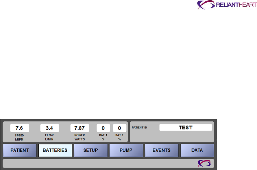
ReliantHeart Confidential – Medical Personnel and Technical Staff 5–7
Each of the six screens also shares a common section across the bottom of the screen
that contains three panes (shown in Figure 5-7):
Status Display pane
Display Select buttons pane
Battery Status indicators pane
Status Display pane
The Status Display pane shows the real-time values for speed, flow, and power; the
percent charge of the battery connected to battery port 2; and the patient’s ID. (See the
PATIENT ID pane on the top, right of Figure 5-7.)
Figure 5-7. Status Display, Display Select, and Battery Status indicators
panes
Display Select buttons pane
Use the Display Select buttons to navigate between the six HeartAttendant® screens.
Select the desired button to open the corresponding screen. All users can access the
PATIENT and BATTERIES screens. The clinician and support staff use the password-
protected SETUP, PUMP, EVENTS, and DATA screens to change VAD settings and to
download event or VAD performance data.
After the clinician or staff enters the password, the system enters tech mode, and all
screens activate until the user exits tech mode on the SETUP screen. (See the Setup
Action pane of Figure 5-16 on page 5-14.)
PATIENT screen
The following sections describe the PATIENT screen panes. The PATIENT screen is
available to all users, including patients and caregivers.
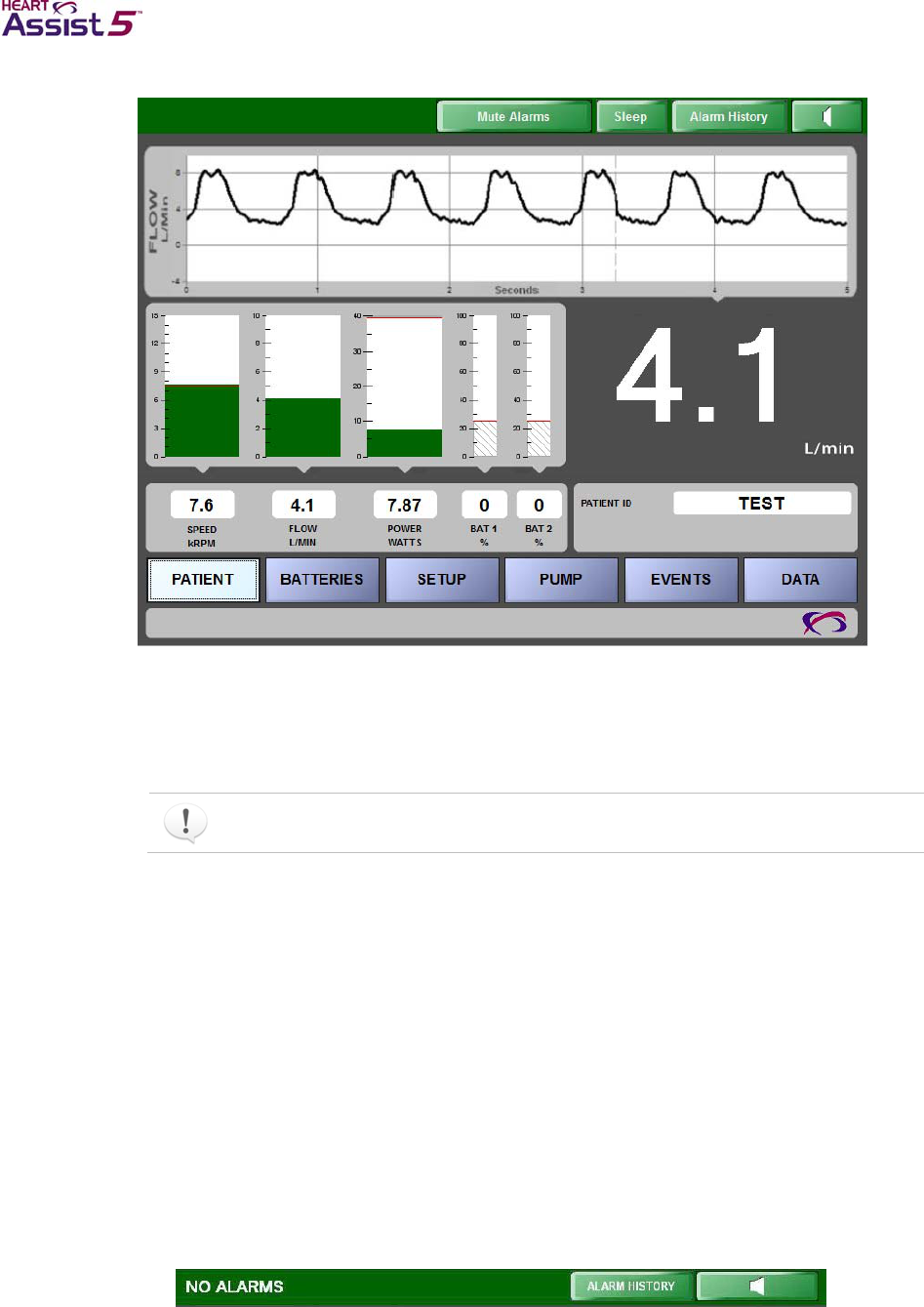
5–8 HeartAssist 5® VAD System Operator’s Manual
Figure 5-8. PATIENT screen
Managing alarms and accessing sleep mode
The following sections describe the Alarm Status bar states, buttons on the bar, and the
corresponding screens associated with each button.
The Alarm Status bar appears on all HeartAttendant® screens.
Alarm Status bar
The Alarm Status bar resides in the thin, horizontal pane across the top of all screens.
The bar remains solid green when conditions are normal (Figure 5-9).
The bar flashes alternating green and yellow when the HeartAttendant® detects a
diagnostic alarm (Figure 5-10).
The bar flashes alternating green and red when the HeartAttendant® detects an
emergency alarm (Figure 5-11).
The Alarm Status bar displays the ALARM HISTORY and Alarm Silence button on all
HeartAttendant® screens. On the PATIENT screen, the Alarm Status bar also displays
the SLEEP button. (See Figure 5-8 for an example of the Alarm Status bar with the
SLEEP button.)
Figure 5-9. Green Alarm Status bar with ALARM HISTORY and Alarm Silence
buttons, indicating normal conditions
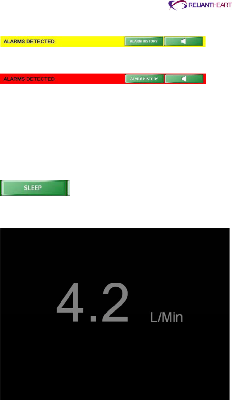
ReliantHeart Confidential – Medical Personnel and Technical Staff 5–9
Figure 5-10. Yellow Alarm Status bar with ALARM HISTORY and Alarm Silence
buttons, indicating diagnostic alarms
Figure 5-11. Red Alarm Status bar with ALARM HISTORY and Alarm Silence
buttons, indicating emergency alarms
SLEEP button
When the patient is sleeping, the operator can press the SLEEP button on the Alarm
Status bar to place the HeartAttendant® into sleep mode, which darkens the display and
only shows minimal information to lessen the light emitted from the HeartAttendant®.
Use the following steps to activate and deactivate sleep mode.
1. Press the SLEEP button on the Alarm Status bar (shown in Figures 5-8 and 5-12).
This button is only visible from the PATIENT screen when the system is not in tech
mode.
Figure 5-12. SLEEP button on the Alarm Status bar
2. Press the Sleep touch screen (shown in Figure 5-13) to return to the PATIENT
screen from sleep mode.
Figure 5-13. Sleep screen
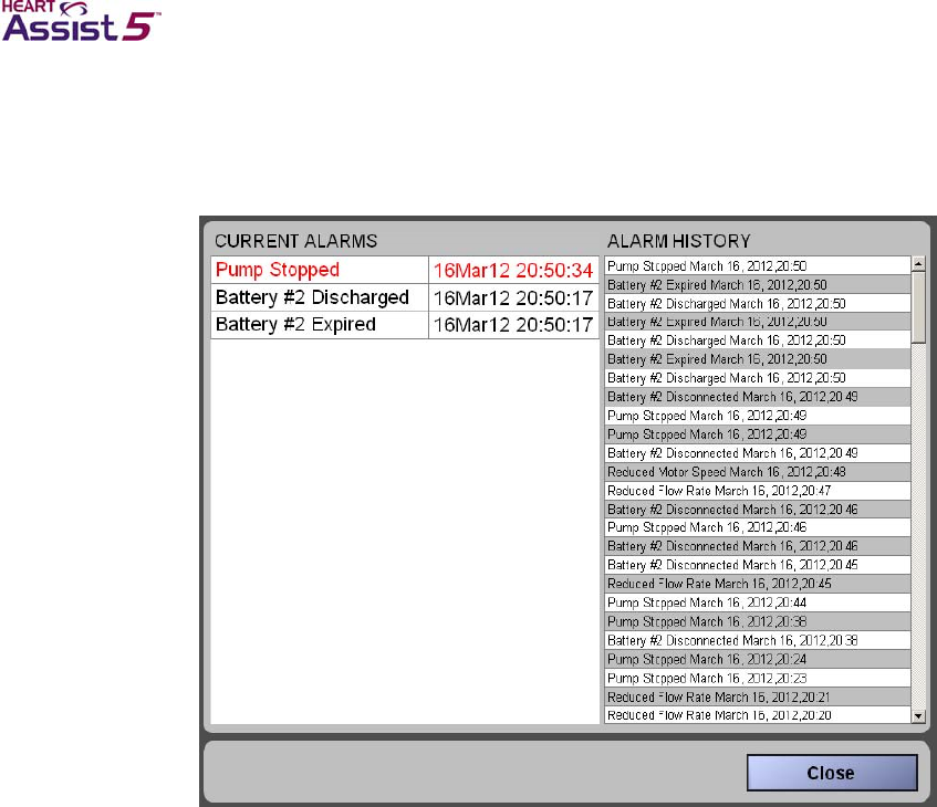
5–10 HeartAssist 5® VAD System Operator’s Manual
ALARM HISTORY button and Alarm window
Press the ALARM HISTORY button on the Alarm Status bar to open the Alarm window
to review alarm messages that are stored in the HeartAttendant®.
Figure 5-14. Alarm window
CURRENT ALARMS pane
The CURRENT ALARMS pane (on the left side of Figure 5-14) lists existing alarms as
they occur while the HeartAttendant® is connected to the Controller, until the alarm
condition resolves and the operator presses the Alarm Silence button. The
HeartAttendant® must be connected to the Controller for the CURRENT ALARMS pane
to display current alarms.
Current alarms also cause the Alarm Status bar to flash. Clear alarm conditions using the
Controller’s Alarm Silence button as soon as practical after they occur to detect a
recurrence of the same alarm.
ALARM HISTORY pane
The ALARM HISTORY pane (on the right side of Figure 5-14) lists previous alarms in
chronological order as they occurred.
The HeartAttendant® must be connected to the Controller for the ALARM HISTORY
pane to display alarm history. The ALARM HISTORY pane lists alarms that occurred
both while the HeartAttendant® was connected and while it was disconnected from the
Controller.
Possible emergency alarms
The following list contains possible emergency alarms that can display in the Alarm
window and trigger a red Alarm Status bar.
Pump Stopped

ReliantHeart Confidential – Medical Personnel and Technical Staff 5–11
Both Batteries Disconnected
VAD Disconnected
For more information about emergency alarms, see “Emergency alarms” on page B-4.
Possible diagnostic alarms
The following list contains possible diagnostic alarms that can display in the Alarm
window and trigger a yellow Alarm Status bar.
Controller Failure
Excess Current
Reduced Flow Rate
Reduced Motor Speed
Pump Restarted
Battery # 1 Disconnected
Battery #1 Discharged
Battery #1 Expired
Battery #2 Disconnected
Battery #2 Discharged
Battery #2 Expired
For more information about diagnostic alarms, see “Diagnostic alarms” on page B-6.
Alarm Silence button
The Controller transmits alarms to the HeartAttendant® as the alarms occur. To clear the
alarms from the Alarm Status bar and the CURRENT ALARMS pane in the Alarm window
and to silence the Controller alarm, press the green Alarm Silence button on the Alarm
Status bar (shown in Figure 5-15).
Figure 5-15. Alarm Silence button
Acknowledging the Controller alarms only silences the Controller audible signal; you
must also press the Controller Alarm Silence button to clear the alarm from the
Controller's LCD and LEDs. Clear alarms as soon as possible after they occur in
order to detect new alarms or a recurrence of the same alarm.
The alarm messages continue to alternately display on the Controller LCD display
until you press the Alarm Silence button on the Controller or until the alarms clear
automatically.

5–12 HeartAssist 5® VAD System Operator’s Manual
Emergency alarms continue to sound and display until you resolve the source of the
alarm. Pressing the Alarm Silence button on the Controller or HeartAttendant® does
not silence the alarm until you resolve the underlying condition.
When the condition causing the emergency alarm no longer exists, the alarm
silences and automatically clears from the CURRENT ALARMS pane in the Alarm
window.
Viewing VAD flow in real time
The flow waveform graph in the FLOW L\Min flow waveform pane plots VAD flow in
liters per minute in real time. The time scale scrolls from left to right and covers a five-
second time span. See Figure 5-8 on page 5-8 for an example of this graph.
Viewing VAD status
The Status Display pane is near the bottom of the PATIENT screen on the left, just
above the Display Select buttons pane. This pane contains four indicator boxes that
display VAD statuses, including speed, flow, power, and battery percent, described in the
following subsections.
The Graphical Display pane is just above the Status Display pane and contains four bar
graphs that correspond with each indicator box in the Status Display pane. These bar
graphs also display alarm thresholds. See “Setting alarm parameter thresholds” on page
5-16 for more information on alarm thresholds.
See Figure 5-8 on page 5-8 for an example of the indicators and graphs discussed in the
following subsections.
The Status Display pane appears on all HeartAttendant® screens.
SPEED kRPM indicator
The SPEED kRPM indicator in the Status Display pane displays VAD speed in thousands
of RPM (kRPM). Set VAD speed between the allowed settings of 7.5 kRPM (7,500 RPM)
and 12.5 kRPM (12,500 RPM). The displayed VAD speed can vary due to pulsatility.
SPEED kRPM graph
The SPEED kRPM graph is directly above the SPEED kRPM indicator. This graph
displays the current VAD speed in a green bar graph and also displays the REDUCED
MOTOR SPEED alarm threshold in a red line.
FLOW L/MIN indicator and large flow display
The FLOW L/MIN indicator in the Status Display pane displays the average flow through
the VAD, which is measured in liters per minute. (The flow waveform pane shows a
graphical display of instantaneous flow.)
FLOW L/MIN graph
The FLOW L/MIN graph is directly above the FLOW L/MIN indicator. This graph
displays the current VAD flow in a green bar graph and also displays the REDUCED
FLOW ALARM threshold in a red line.

ReliantHeart Confidential – Medical Personnel and Technical Staff 5–13
POWER WATTS indicator
The POWER WATTS indicator in the Status Display pane displays the watts used by the
VAD and motor controller together. (This data excludes CPU and flow sensor power
requirements.)
POWER WATTS graph
The POWER WATTS graph is directly above the POWER WATTS indicator. This graph
displays the current VAD power consumption in a green bar graph and also displays the
EXCESS CURRENT alarm threshold in a red line.
BATTERY % indicator
The BATTERY % indicator in the Status Display pane displays the battery charge level
as a percent of full capacity for the battery connected to battery port 2.
BATTERY % graph
The BATTERY % graph is directly above the BATTERY % indicator. This graph displays
the battery charge level in a green bar graph and also displays the BATTERY
DISCHARGED alarm threshold as a red line.
L/min large flow display
The large L/min flow display in the center, right of the screen displays the average flow
through the VAD in liters per minute in a larger format.
Viewing the patient ID
The PATIENT ID pane (shown in Figure 5-8 on page 5-8) displays the current patient
directory folder name in the operating system.
To change the patient directory, see “Changing patient directories” on page 5-23.
SETUP screen
Use the SETUP screen to enter all operational data for the Controller. Configure the
Controller before a patient is implanted. (See “Preparation for implant” on page 3-3.)
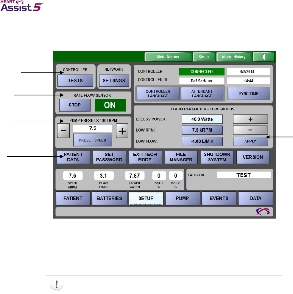
5–14 HeartAssist 5® VAD System Operator’s Manual
Figure 5-16. SETUP screen
Running Controller tests
Use the TESTS button in the top, left CONTROLLER pane to select the desired
diagnostic test. View the results in the Test Results window. Some of the tests require
monitoring the Controller.
Only execute these tests prior to surgery or while the VAD and patient are stable.
Some tests can take several seconds to complete.
Available tests include the following:
Test Message/Parameter EEPROM
Test LED Annunciators
Test Audible Annunciators
Test LCD Display
Viewing the Controller communication status and ID and setting the language,
date, and time
The following controls display on the CONTROLLER/CONTROLLER ID pane on the
SETUP screen.
Controller pane
Rate Flow Sensor pane
Pump Preset pane
Setup Action pane
Alarm
Parameter
Thresholds
pane
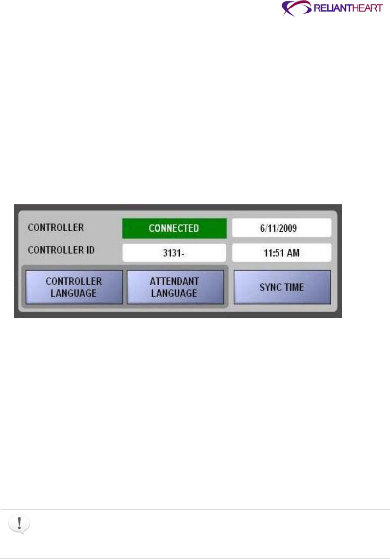
ReliantHeart Confidential – Medical Personnel and Technical Staff 5–15
Controller communication status
The first box on the CONTROLLER row of the CONTROLLER/ CONTROLLER ID pane
is green and displays the word CONNECTED if the Controller is connected and
communicating properly with the HeartAttendant®.
Date
The right box on CONTROLLER row displays the date for the connected Controller.
Controller ID (serial number)
The first box in the CONTROLLER ID row displays the serial number of the Controller
connected to the HeartAttendant®.
Figure 5-17. Controller/Controller ID pane of the SETUP screen
Time
The right box on the CONTROLLER ID row displays the set time of the connected
Controller.
CONTROLLER LANGUAGE button
Use the following instructions to set the language to display on the Controller screens.
1. Press the CONTROLLER LANGUAGE button in the Controller/Controller ID pane
of the SETUP screen. A dialog box with a drop-down menu of languages opens.
2. Select and download the appropriate language.
After you select and download your language, this language appears on the
Controller display screens.
Set the Controller language before surgery begins. This action takes approximately
one minute to complete. Do not disconnect the Controller from the HeartAttendant®
for at least one minute after selecting the language. (See “Preparing the Controllers
using the HeartAttendant®” in Chapter 3 on page 3-5 for instructions.)
ATTENDANT LANGUAGE button
Use the following instructions to set the language to display on the PATIENT screen.
1. Press the ATTENDANT LANGUAGE button. A dialog box opens.
2. Select the appropriate language to display on the PATIENT screen.

5–16 HeartAssist 5® VAD System Operator’s Manual
SYNC TIME button
The SYNC TIME button allows you to sync the HeartAttendant® date and time with the
Controller. Use the following steps to reset the Controller date and time to correspond
with the HeartAttendant®.
1. Connect the Controller to the HeartAttendant®.
See “Connecting the Controller to the HeartAttendant®” on page 5-4.
2. Press the SETTINGS button and the SYNC TIME button.
Deactivating the flow sensor
Use the STOP button in the RATE FLOW SENSOR pane to deactivate the flow sensor
function. You can disable the flow rate sensor circuit in the Controller to conserve energy
or if its data become uninterpretable (for example, if the A and B received amplitude,
which you can view on the PUMP screen, are both less than 1.0 volt). The RATE FLOW
SENSOR pane indicates the current state of the flow rate sensor circuit.
Presetting VAD speed
Use the PRESET SPEED button to set a default VAD speed in the Controller.
1. Use the + and -buttons to increase or decrease the preset VAD speed that is
displayed in the PUMP PRESET pane. See Figure 5-16 on page 5-14.
2. Press the PRESET SPEED button to save the new default VAD speed.
3. Wait 16 seconds before initiating any other HeartAttendant® commands.
The preset speed function on the SETUP screen is only available when a Controller
is connected and the VAD is not running. If a Controller is connected and running a
VAD, then you must change the speed on the PUMP screen of the HeartAttendant®.
See “Viewing the pump status and adjusting the VAD speed” on page 5-19 for
instructions for changing the VAD speed on the PUMP screen.
Setting alarm parameter thresholds
The controls described in the following subsections allow you to set the upper and lower
alarm parameter limits for power, flow, RPM, and battery level. The thresholds display as
red bars on the PATIENT screen, are stored in the Controller, and control the audible
alarms. See Figure 5-16 on page 5-14 for an example of these controls.
EXCESS CURRENT threshold
Use the + and – buttons to set excess current threshold to an appropriate number of
watts for discharge.
1. In the ALARM PARAMETERS THRESHOLDS pane, press the blue Watts button to
the right of EXCESS CURRENT.
2. Press the + button to increase or the – button to decrease the alarm threshold for the
EXCESS CURRENT alarm. See Figure B-11 on page B-7 for an example of this
alarm.
3. Press the APPLY button.

ReliantHeart Confidential – Medical Personnel and Technical Staff 5–17
LOW RPM threshold
Use the + and – buttons to increase or decrease the RPM alarm threshold to a value
between 7.5 kRPM (7,500 RPM) and 12.5 kRPM (12,500 RPM). Setting this alarm
threshold to 7.5 inhibits this alarm on the Controller.
1. In the ALARM PARAMETERS THRESHOLDS pane, press the blue kRPM button to
the right of LOW RPM.
2. Press the + button to increase or the – button to decrease the alarm threshold for
RPMs.
3. Press the APPLY button.
LOW FLOW threshold
Use the + and – buttons to increase or decrease the flow alarm threshold in 0.2 L/min
increments to a value between –4 L/min and 6 L/min.
1. In the ALARM PARAMETERS THRESHOLDS pane, press the blue L/Min button to
the right of LOW FLOW.
2. Press the + button to increase or the – button to decrease the alarm threshold for
flow.
3. Press the APPLY button.
Battery % threshold
The battery threshold is automatically set to alarm when a battery depletes to a 25%
charge level.
Using the Setup Action buttons
See Figure 5-16, “SETUP screen,” on page 5-14 for an example of the buttons in the
Setup Action pane.
The Setup Action buttons are password protected. The password is the same as the
tech mode password. Knowledge of this password should be restricted to personnel
responsible for maintaining patient data files for ReliantHeart.
PATIENT DATA button
Press the PATIENT DATA button to open a dialog box containing a patient data form.
Use this form to modify the patient data stored in the Controller.
The operating system uses the data you enter in the Patient ID text box as the
directory folder name. This directory cannot contain the following characters:
\ / : ? < > |*
Do not enter the above characters in the Patient ID text box.
SET PASSWORD button
Press the SET PASSWORD button to open a dialog box containing a form for changing
the tech mode and Setup Action buttons password.
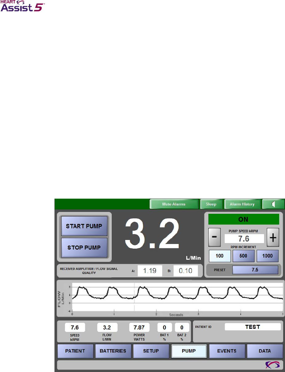
5–18 HeartAssist 5® VAD System Operator’s Manual
EXIT TECH MODE button
Press the EXIT TECH MODE button to return to the PATIENT screen. A member of the
support team or hospital staff must re-enter the password to return to tech mode after
exiting that mode.
FILE MANAGER button
The FILE MANAGER button starts the Windows Explorer file manager application. This
feature is not designed to edit sored controller data, but allows the HeartAttendant user to
locate and re-arrange controller data previously downloaded. Please operate the FILE
MANAGER button only with the support of ReliantHeart.
SHUTDOWN SYSTEM button
The SHUTDOWN SYSTEM button begins an orderly power-down of the HeartAttendant®
system.
PUMP screen
Use the controls on the PUMP screen during implant, explant, and VAD control
adjustment to increase or decrease the VAD speed and to start and stop the VAD.
Figure 5-18. PUMP screen
Starting and stopping the VAD
Use the START PUMP and STOP PUMP buttons to activate and deactivate the VAD.
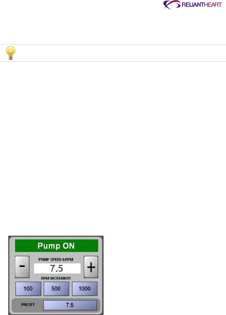
ReliantHeart Confidential – Medical Personnel and Technical Staff 5–19
START PUMP button
The START PUMP button starts the VAD.
The START PUMP button has no effect if the VAD is already running.
STOP PUMP button
The STOP PUMP button stops the VAD and triggers a three-second audible emergency
alarm.
Viewing the pump status and adjusting the VAD speed
The colored Pump Status box on the Pump Speed pane on the top, right of the PUMP
screen displays the current state of the VAD.
Red Pump Status box
When the Pump Status box is red and displays Pump OFF, the VAD is not running.
Green Pump Status box
When the Pump Status box is green and displays Pump ON, the VAD is running.
Yellow Pump Status box
When the Pump Status box is yellow and displays PUMP CONDITION UNKNOWN, the
VAD could be on or off, but the HeartAttendant® cannot currently determine the state of
the pump (possibly due to communication errors).
Figure 5-19. Pump Status box in the Pump Speed pane
PUMP SPEED kRPM indicator
View the current VAD speed in the PUMP SPEED kRPM indicator box under the Pump
Status box.
RPM INCREMENT buttons
You can increase or decrease the speed using one of the three RPM INCREMENT
buttons.
Use the following steps to increase or decrease the VAD speed by a specific increment.

5–20 HeartAssist 5® VAD System Operator’s Manual
1. Press an RPM INCREMENT button (with values of either 100, 500, or 1000) to
increase or decrease the VAD speed by the value on that button.
2. Press the – button to decrease the speed, or press the + button to increase the
speed.
VAD speed can only be adjusted (increased or decreased) when the VAD is running.
PRESET button
Use the PRESET button to change the VAD speed back to the default preset value
specified on the SETUP screen. (See “Presetting VAD speed” on page 5-16.)
Use the following steps to change the VAD speed to the preset VAD speed value. If you
have already specified a VAD speed preset on the SETUP screen, begin with step 3.
1. Press the SETUP button to access the SETUP screen.
2. Follow the instructions in “Presetting VAD speed” on page 5-16 to specify a default
VAD speed.
3. Press the PUMP button to access the PUMP screen.
The PRESET button on the PUMP screen displays the default VAD speed specified
on the SETUP screen.
4. Press the PRESET button on the PUMP screen to change the VAD speed to the
default value specified in step 2.
Viewing the flow waveform graph
The graph in the FLOW L\Min flow waveform pane (see Figure 5-18 on page 5-18) plots
VAD pump flow in liters per minute in real time.
The time scale scrolls from left to right and covers a five-second time span. This pane is
the same as the FLOW L/MIN flow waveform pane on the PATIENT screen.
EVENTS screen
Use this screen to retrieve and display selected data that is currently stored in the
Controller event memory or to retrieve historic event memory data that is stored on the
HeartAttendant® hard disk. A pump stoppage triggers and event to be captured within
the controller memory and the pump parameters within a 55 second or 30 minutes time
interval can be analyzed.
The 180 day button downloads a file that has stored flow, power and speed data every
minute for up to 180 days.
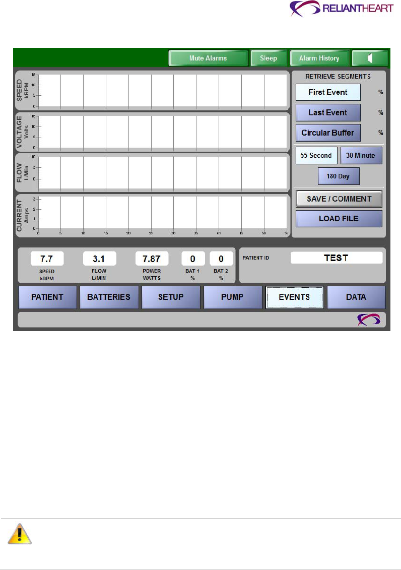
ReliantHeart Confidential – Medical Personnel and Technical Staff 5–21
Figure 5-20. EVENTS screen
Viewing event data
The four graphs in the Event Memory panes on the top, left of the EVENTS screen
display data currently stored in the selected memory segments of the Controller:
SPEED
kRPM
VOLTAGE
Volts
FLOW
L/Min
CURRENT
Amps
Do not disconnect the HeartAttendant® from the Controller during an event
memory download (approximately 60 seconds per segment). Wait for 10
seconds after the comment box closes. Disconnecting the HeartAttendant®
before data downloading completes can cause loss of data.
Retrieving data segments
Use the buttons in the RETRIEVE SEGMENTS pane to view data stored in the selected
segment in the Event Memory panes.
The circular buffer checks data every 60 seconds. When an event occurs, the First Event
space stores that data. When a second event occurs, the Last Event space stores the
data. If a subsequent event occurs, that data overwrites the existing data in the Last
Event space. The Last Event space always contains the most recent event.

5–22 HeartAssist 5® VAD System Operator’s Manual
The First Event and Last Event can be analyzed with 3 individual time intervals: 55
second or 30 minute. The data retrieved for the first and last events display speed,
voltage, flow, and current in the time period occurring before the event. For example, if
the First Event were selected by choosing the 55 second button, the 55 seconds of
recorded parameters prior to the event will be stored and displayed.
Viewing the first event
Use the 55 second or 30 minute button to designate the time interval.Use the First Event
button to view the first event that occurred.
1. Press the EVENTS button to access the EVENTS screen.
2. Press the First Event button.
3. Press the START DOWNLOAD button.
The first event data display in the Event Memory panes.
Viewing the last event
Use the 55 second or 30 minute button to designate the time interval.
Use the Last Event button to view the most recent event that occurred.
1. Press the EVENTS button to access the EVENTS screen.
2. Press the Last Event button.
3. Press the START DOWNLOAD button.
The most recent event data display in the Event Memory panes.
If a PUMP STOPPED alarm has not occurred since the Controller powered up and
prior to download, the Controller displays the default values of 0 in the first and last
segments for VOLTAGE, FLOW, and CURRENT. The default value of SPEED is
12.5.
Inputting comments with event memory data
The COMMENTS button opens a dialog box that allows you to store comments with the
event data. The comments dialog box is prepopulated with the patient ID and the date
and time of the event. The HeartAttendant® automatically saves these comments with
event data, which you can then recall and modify when you retrieve the event data. (See
“Displaying and entering comments for currently displayed data” on page 5-25 for
information on retrieving comments.)
After you save the comments in this dialog box, the HeartAttendant® instructs the
Controller to clear the event memory segment. This process takes approximately six
seconds.
Use the following instructions to save comments with event memory data.
1. Press the EVENTS button to access the EVENTS screen.
2. Press one of the following:
Press the First Event button to view the first event.
Press the Last Event button to view the most recent event.
3. Press the START DOWNLOAD button.

ReliantHeart Confidential – Medical Personnel and Technical Staff 5–23
The START DOWNLOAD button now reads CANCEL DOWNLOAD.
Press this button if you want to stop the process.
The EVENTS screen displays the download progress in percent downloaded under
the CANCEL DOWNLOAD button. When the percent downloaded reaches 100%
Completed, the data display in the Event Memory panes.
4. Press the COMMENTS button after the data is 100% downloaded. The HolterFile -
Enter comments dialog box opens.
Pressing the COMMENTS button only initiates an action after you save an event
using steps 1 through 3.
5. Press the EDIT button on the HolterFile - Enter comments dialog box. The on-screen
keyboard displays. The dialog box is prepopulated with the patient ID and the date
and time of the event.
6. Type your comments in the dialog box.
7. Press the SAVE button on the HolterFile - Enter comments dialog box.
The HeartAttendant® saves the comments with the event data.
Changing patient directories
The HeartAttendant® stores files in directories that correspond with the patient's ID. If a
Controller is connected to the HeartAttendant®, the current directory defaults to the
patient ID of the connected Controller.
Use the following instructions to change the patient directory (only for viewing a different
patient's saved event files).
1. Press the LOAD FILE button.
A drop-down menu opens that displays the files for all patients.
2. Select the patient file to display.
Loading previously saved event files
To view a previously downloaded and saved event memory file, press the LOAD FILE
button; then select the file.
The HeartAttendant® stores the files in the format holxx-yymmdd_hhmmss.hol, where xx
represents the saved segment in the file, yymmdd represents the date on which the file
was saved, and hhmmss represents the time in which the file was saved (on a 24-hour
clock).
For example, a file named hol01-120411_104033.hol is a last event segment saved on
April 11, 2012 at 10:40:33 a.m.
DATA screen
The DATA screen allows real-time acquisition and storage of power and flow data. This
screen allows you to export data, enter commands, and take and retrieve screenshots.
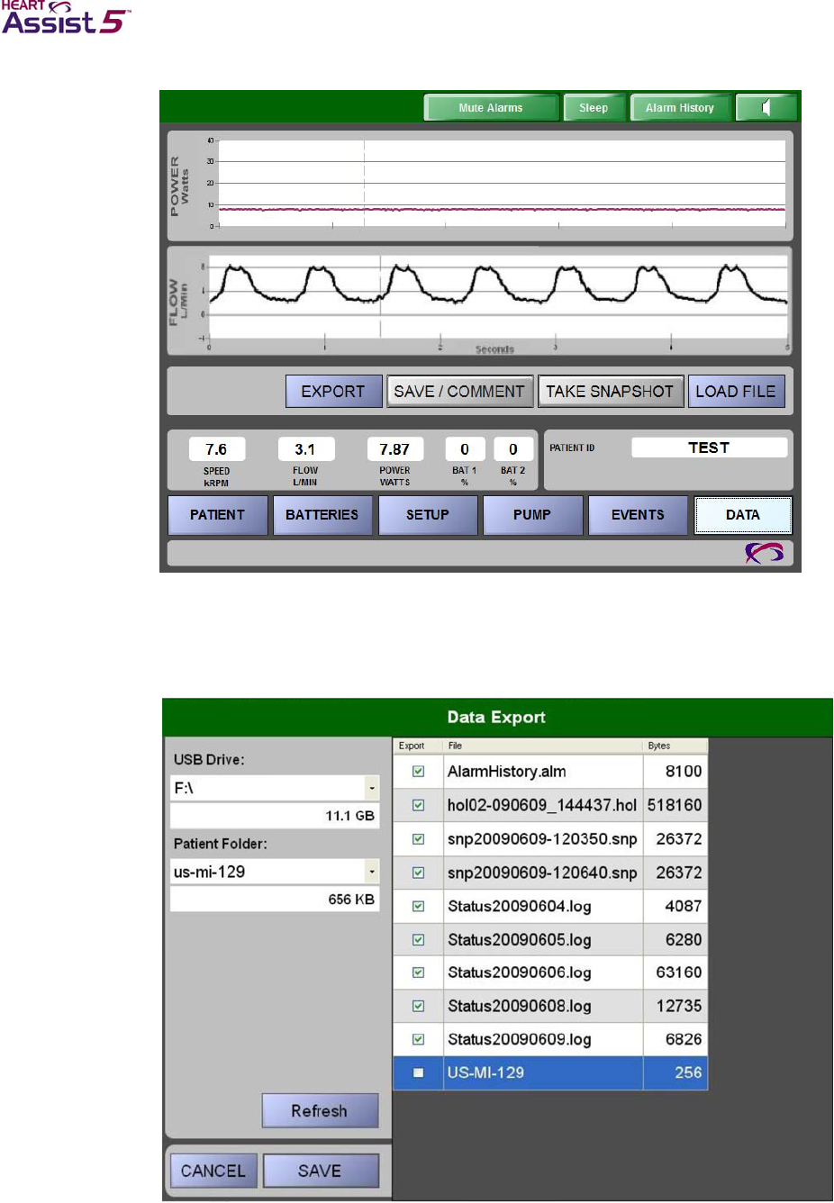
5–24 HeartAssist 5® VAD System Operator’s Manual
Figure 5-21. DATA screen
Exporting patient data
You can export patient data to a USB flash drive using the following instructions.
Figure 5-22. Data Export dialog box
1. Insert a USB drive into the USB slot on the HeartAttendant®.

ReliantHeart Confidential – Medical Personnel and Technical Staff 5–25
2. Press the PATIENT button to navigate to the PATIENT screen.
The PATIENT screen displays.
3. Record the patient ID in the PATIENT ID pane.
See “Viewing the patient ID” on page 5-13.
4. Press the DATA button to navigate to the DATA screen.
5. Type the password if prompted.
The DATA screen displays.
6. Press the EXPORT button.
The Data Export dialog box opens.
7. In the Patient Folder drop-down menu, select the patient ID that you recorded in step
3.
8. In the Export column on the right pane, select the check boxes for the files that you
want to copy to the USB drive.
Table 5-1 lists the file extensions available for exporting.
Table 5-1. File types available for exporting
File type File description
Status*.log Status log files, recorded automatically, one file per day, 110
Kb/day, one entry per minute
AlarmHistory.alm Alarm history file, updated continuously as alarms are recorded
*.hol Event memory files, downloaded from the Controller, 507 Kb/each
*.snp Snapshot files from the DATA screen, 26 Kb/each
Copy files to the USB flash drive. Do not delete any files from the
HeartAttendant
®
.
9. Press the SAVE button.
10. Remove the USB drive from the HeartAttendant®.
11. Email all files to patientdata@reliantheart.com.
Type the patient ID in the Subject field, and send each patient's data in a separate
email message.
12. After you have successfully emailed the files, delete the confidential patient data from
the USB drive.
Displaying and entering comments for currently displayed data
Use the COMMENTS button to display and type comments corresponding to the
currently displayed data.
This button and its corresponding dialog box have the same functionality as the
COMMENTS button on the EVENTS screen. See “Inputting comments with event
memory data” on page 5-22 for detailed instructions for inputting comments.

5–26 HeartAssist 5® VAD System Operator’s Manual
Obtaining screenshots
Use the TAKE SNAPSHOT button to obtain and store a screenshot of five seconds of the
current waveform on the screen.
To view the screenshot, see the next section, “Retrieving screenshots.”
Retrieving screenshots
Use the following steps to view a previously downloaded and saved screenshot in snap
file format.
1. Press the DATA button.
The DATA screen displays.
2. Press the LOAD FILE button.
The current patient’s saved screenshots display.
3. Select the screenshot to display.
4. Highlight the screenshot that you want to view.
5. Press the Select button to view the highlighted file.
The selected screenshot displays.
6. Press the Show Live Data button to return to the DATA screen.
Changing patient directories
The HeartAttendant® stores screenshots in snap file format in directories corresponding
with the patient's ID. If a Controller is connected to the HeartAttendant®, the current
directory defaults to the patient ID of the connected Controller.
To change this directory (only for viewing a different patient's screenshots), use the
following steps.
1. Press the DATA button.
The DATA screen displays.
2. Press the LOAD FILE button.
The current patient’s saved screenshots display, and the Patient Folder dialog box
opens with a drop-down menu that displays the directories for all patients.
3. Select the appropriate patient ID in the drop-down menu of the Patient Folder dialog
box.
The selected patient’s files display.
4. Highlight the screenshot that you want to display.
5. Press the Select button to view the highlighted file.
6. Press the Show Live Data button to return to the DATA screen.
Snap file format
The HeartAttendant® stores screenshots in snap files in snpyyyymmdd-hhmmss.snp
format, where yyyymmdd represents the date on which the file was saved, and hhmmss
represents the time in which the file was saved (on a 24 hour clock).
For example, the file named snp20120411-104033.snp is a screenshot saved on April 11,
2012 at 10:40:33 a.m.

ReliantHeart Confidential – Medical Personnel and Technical Staff 5–27
Cleaning and maintenance
Use the following steps to maintain the cleanliness of the HeartAttendant®.
Cleaning the HeartAttendant®
Wipe the outer case of the HeartAttendant® with a slightly damp cloth, then wipe the
case with isopropanol to remove contaminants. Do not allow liquid to spill into the
HeartAttendant® components.
Always unplug the HeartAttendant® before cleaning it.
Maintaining the HeartAttendant®
The HeartAttendant® contains no user serviceable parts. Contact for service at the
phone number listed on page iii. Replace the HeartAttendant® connector cable if the
cable shows any signs of functional or visible damage.
Transporting the HeartAttendant®
You must place theHeartAttendant® on a secure surface. Use caution when moving it.
Do not allow the HeartAttendant® to tip at more than a 30° degree angle.
Transport the HeartAttendant® from location to location while it is powered off.
Dropping the HeartAttendant® while it is connected can cause injury.
Disconnect the HeartAttendant® connector cable prior to moving the
HeartAttendant®.
To carry the HeartAttendant®, grasp the top handle and the bottom handle near the front
of the unit, and carry it close to your body for maximum support and comfort.
Contact before shipping the HeartAttendant® to another location. can provide a
replacement shipping box with custom packing inserts for safe transport.
Hazards
Use the information in the following subsections to prevent damage and injury from
electrical hazards.
Grounding the HeartAttendant®
Before you make any connection to the Controller input, you must connect the
HeartAttendant® to a protective earth ground via the three-core mains cable supplied.
Only insert the mains plug into a socket outlet provided with a protective earth contact.

5–28 HeartAssist 5® VAD System Operator’s Manual
Verifying local mains voltage
Before plugging the HeartAttendant® into an electrical outlet, ensure that the
HeartAttendant® is configured for local mains voltage. See “Powering on the
HeartAttendant®” on page 5-3 to verify the voltage configuration.
The following list contains warnings typical to medical electrical equipment, which also
apply to the HeartAttendant®. These warnings appear on HeartAttendant® labeling.
The HeartAttendant® must be disconnected from all voltage sources when a fuse is to
be replaced.
The nominal mains voltage and frequency is 120VAC-60Hz or 240VAC-50Hz.
Replacing fuses
The rear panel of the HeartAttendant® contains a fuse holder in the mains input socket.
Use the following steps to replace the mains fuse.
See Figure 5-23 for an example. For information on obtaining replacement fuses, see
“Connecter cables, power cords, and fuses” on page C-7.
1. Disconnect the HeartAttendant® AC power cord from the mains, and verify that the
HeartAttendant® is disconnected from all other voltage sources.
2. Remove the cover of the fuse holder using a small screwdriver.
Figure 5-23. Mains input socket on the rear panel of the HeartAttendant®
3. Fit a new fuse of the correct rating according to the rear label of the HeartAttendant®.
4. Reinsert the fuse holder into the power inlet module.
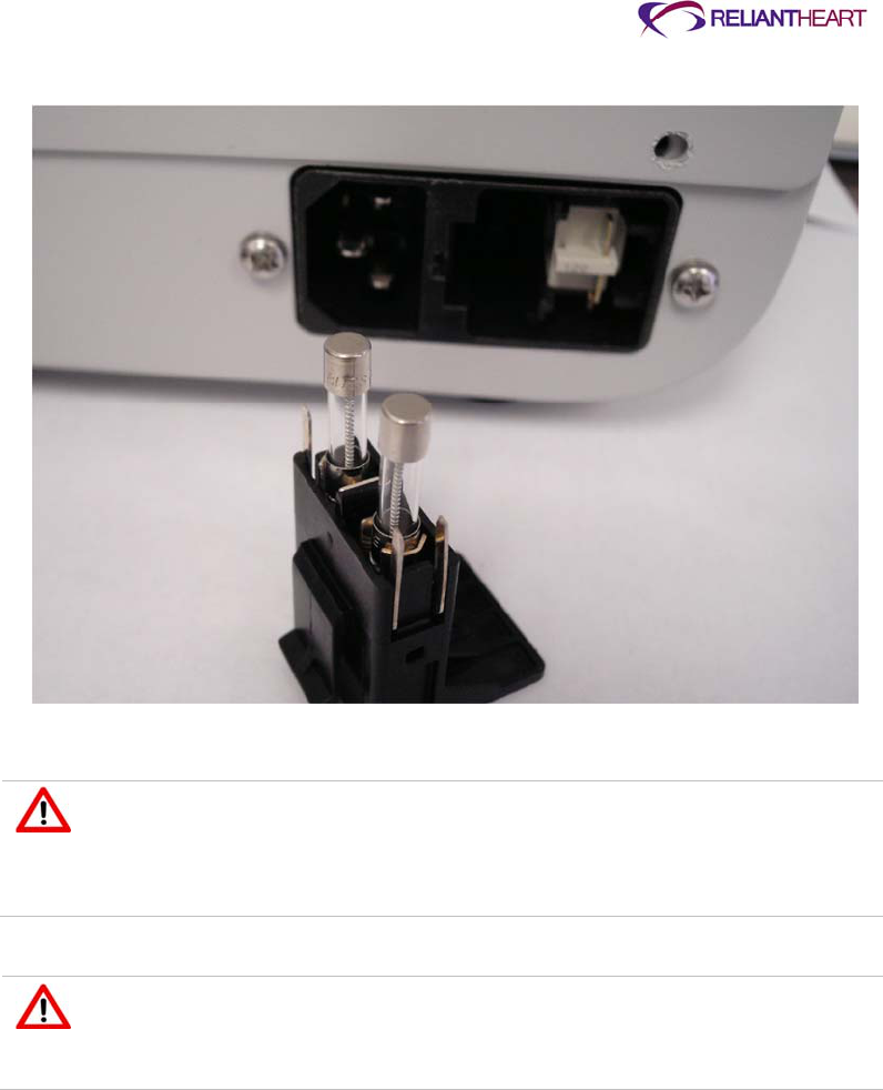
ReliantHeart Confidential – Medical Personnel and Technical Staff 5–29
Figure 5-24. Fuse block in power inlet module
5. Power on the HeartAttendant®, and verify that it boots up normally.
Only use fuses supplied by for the HeartAttendant®. When changing fuses,
fully snap the fuse block back into place. Only use replacement fuses with the
required current rating and of the specified type as listed on the rear panel of
the HeartAttendant®. The use of makeshift fuses or short circuiting of the fuse
holder is prohibited.
Any interruption of the protective conductor inside or outside the
HeartAttendant® while the mains are connected is likely to make the device
dangerous. Intentional interruption of the protective conductor is prohibited
while the mains are connected.

ReliantHeart Confidential – Medical Personnel and Technical Staff 6–1
Chapter 6
Everyday Use and Self Care
In this chapter
Introduction ................................................................................................................................... 6-2
System management .................................................................................................................... 6-2
Upon waking .................................................................................................................... 6-2
Before sleeping ................................................................................................................ 6-2
Daily operation .............................................................................................................................. 6-3
Tethered operation ........................................................................................................... 6-3
Untethered operation ....................................................................................................... 6-3
Switching from tethered to untethered operation ............................................................. 6-4
Switching from untethered to tethered operation ............................................................. 6-5
Showering with the VADPAK Insert and shower bag ...................................................... 6-6
Activity restrictions ........................................................................................................... 6-8
Caring for the exit site ................................................................................................................... 6-9
Caring for the percutaneous cable ................................................................................. 6-10
Caring for the VADPAK .................................................................................................. 6-10
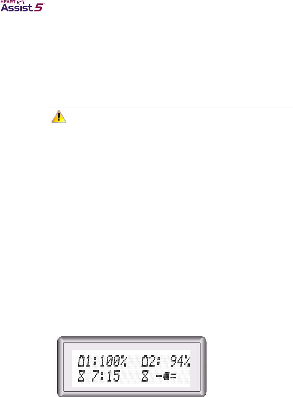
6–2 HeartAssist 5® VAD System Operator's Manual
Introduction
Hospital staff should initially supervise system management, and then, as appropriate,
transfer management to the patient.
System management
Check the Controller, the primary and reserve batteries, the Independent Power Supply,
and the LVAD Battery Charger every day as described below.
Contact ReliantHeart if any of the Controller alarms are not working.
Every two – three hours when the patient is awake (whether the patient is
attached to the Independent Power Supply or the HeartAttendant® or not),
check the battery status on the Controller front panel.
Upon waking
When the patient wakes in the morning, check the front panel display of the Controller for
lighted symbols and messages. If the Controller is displaying alarm messages, see
“Emergency alarms” on page B-4 and “Diagnostic alarms” on page B-6.
Before sleeping
Before the patient goes to sleep, ensure that you verify the following statuses:
Verify that the battery status lights are lit for all reserve batteries in the LVAD Battery
Charger.
Verify that you have two fully charged batteries in the battery pockets.
Verify that the Independent Power Supply is supplying power to the Controller by
performing the following steps:
a. Verify that the battery LED on the Controller’s front panel is solid green for the
battery pocket connected to the Independent Power Supply.
b. Press the Scroll Display button on the front panel of the Controller to verify that the
battery percentage is displaying the external power indicator (a plug symbol) for
the battery pocket connected to the Independent Power Supply.
Figure 6-1. Standard message screen 1 display on the Controller front panel
when using external power

ReliantHeart Confidential – Medical Personnel and Technical Staff 6–3
Daily operation
Always connect the Controller to two power sources. The VAD draws power from one
source at a time. The second source serves as backup power. When the patient is using
the two batteries in the battery pockets as the primary and backup power sources, ensure
that you check the remaining charge in each battery every hour.
While the patient is relaxing or sleeping, use the HeartAttendant® or the Independent
Power Supply in the tethered mode of operation (described in the following section).
When the patient is active, you usually use the batteries in the battery pockets in the
untethered mode of operation. The system is not connected to the Independent Power
Supply or the HeartAttendant® during this time.
Tethered operation
During times of little activity, such as when the patient is sleeping or relaxing, you should
use the HeartAttendant® or the Independent Power Supply. This method is called
tethered operation. The HeartAttendant® is only used for monitoring the patient’s
condition while the patient is in the hospital.
The system must be in tethered mode whenever you think the patient might fall asleep or
if charged batteries are not available for use in the battery pockets.
When you use the Independent Power Supply, or the HeartAttendant®, the Controller
uses power from the grounded AC wall outlet. The Controller can also receive backup
power from the batteries in the battery pockets if the wall fails.
Untethered operation
When active, most patients prefer using the batteries in the battery pockets (untethered
operation) instead of having the system plugged into the Independent Power Supply in
tethered mode.
The battery pockets must contain two fully charged batteries before you switch the
patient to untethered mode. The Controller draws power from one battery until it reaches
25% before drawing power from the second battery. Once at 25% charge, the controller
switches to the second battery until it reaches 25%. This design ensures that the second
battery will have energy remaining when the first battery falls below a 25% charge level. If
both batteries are at or below 25%, the controller switches back to the first battery and
drains until 15% and switches to second battery. At this time, both batteries are at or
below 15% charge and must be replaced to prevent pump stoppage.
Each fully charged battery powers the VAD for approximately 4.5 – 7.5 hours, giving a
combined battery time of approximately 9 – 15 hours. Higher VAD speeds can reduce
battery charge levels. The Controller front panel displays the percent charge level for
each battery.
A fully charged battery provides adequate power to run the VAD for 4.5 – 7.5 hours.
If the VAD speed is set high, it reduces the amount of time the battery can operate
the VAD.
The amount of time that the patient stays in untethered operation depends on the set
VAD speed and the number of reserve batteries available.
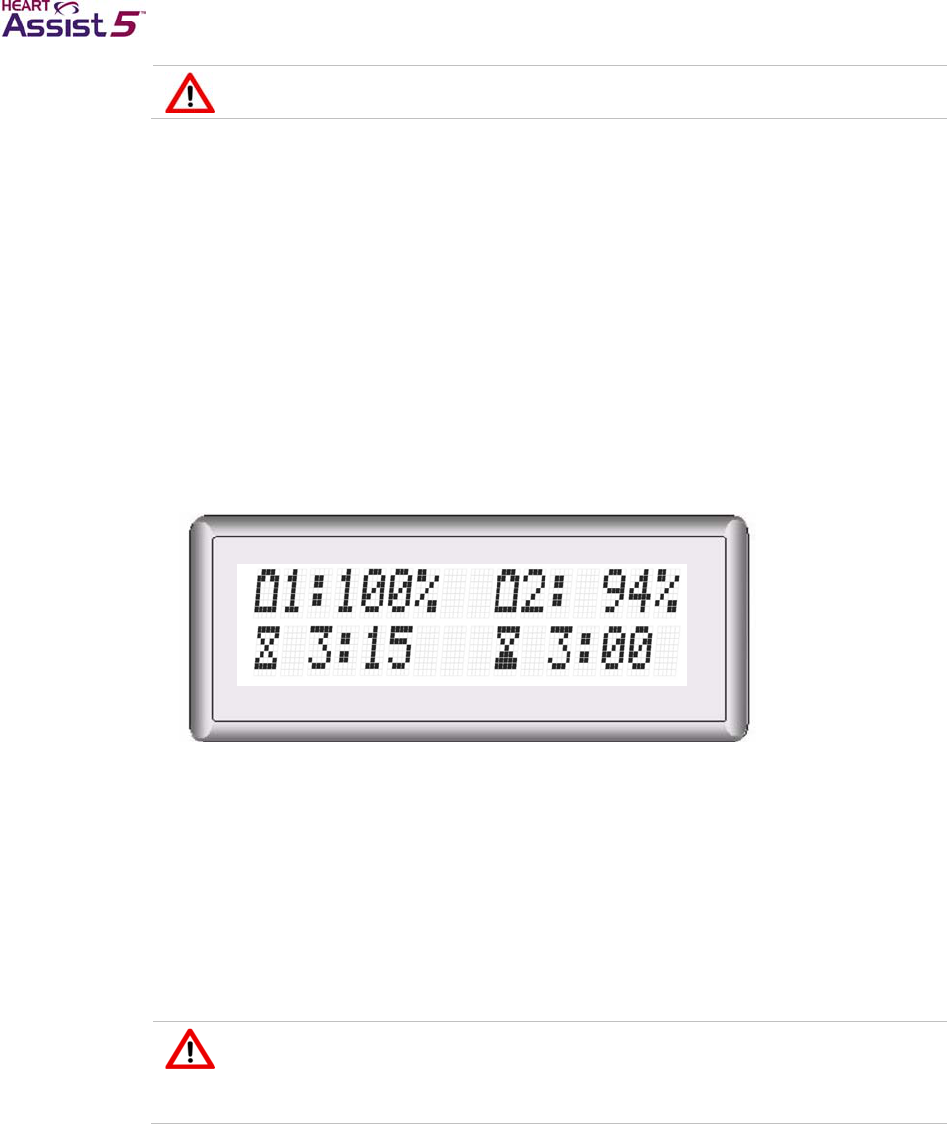
6–4 HeartAssist 5® VAD System Operator's Manual
Only use batteries supplied by ReliantHeart
Switching from tethered to untethered operation
Use the following steps to change the power source from tethered to untethered
operation.
Verifying battery charge
Use the following steps before disconnecting the patient from the Independent Power
Supply or the HeartAttendant®.
Verify that the charge level of the two batteries connected to the Controller is nearly full
(>80%) on the Controller front panel.
Figure 6-2. Standard message screen 1 display on the Controller front panel
when using battery power
If one or both batteries are not near charge capacity, proceed as follows:
1. Remove one or two fully charged batteries from the LVAD Battery Charger.
2. Check the batteries by pushing the charge indicator button on each battery to verify
charge level.
3. Remove only one discharged battery from the battery pocket and insert the fully
charged battery.
4. Remove the second discharged battery from the battery pocket and insert the fully
charged battery.
Only remove one battery at a time from the battery pockets. Removing both
batteries simultaneously causes the VAD to stop (unless the patient is in
tethered mode). The batteries must be reconnected as quickly as possible to
resume VAD function.
5. Check the charge level of the new battery connected to the Controller on the
Controller front panel.
Disconnecting from the Independent Power Supply or the HeartAttendant®
Use the following steps to disconnect the battery pocket from the Independent Power
Supply, or the HeartAttendant®, and complete the process of switching to untethered
operation.
Disconnect the Independent Power Supply or the HeartAttendant® from the battery
pocket external power connector as follows:

ReliantHeart Confidential – Medical Personnel and Technical Staff 6–5
1. With one hand, firmly hold the battery pocket external power connector.
2. With the other hand, pull the power source connector from the battery pocket external
power connector.
This connection might be tight and might take some force to pull loose.
Do not twist the connector while removing it. Do not pull on the cables.
During untethered operation, check the charge level of both batteries in the battery
pockets every hour to ensure that enough power is available.
Always disconnect the HeartAttendant® or the Independent Power Supply connector
from the battery pocket external power connector before removing power to or
turning off the Independent Power Supply or the HeartAttendant®.
Switching from untethered to tethered operation
Use the following steps to change the power source from untethered to tethered
operation.
Verifying Readiness
Ensure that the Independent Power Supply or the HeartAttendant® is ready to be used.
Verify that the system status light of the Independent Power Supply is a steady green
or the HeartAttendant® screen is illuminated.
Connecting to the battery pocket external power connector
Use the following general steps to connect the power source connector (Independent
Power Supply connector or the HeartAttendant® to the battery pocket external power
connector.
1. Visually align the arrow on the power source connector with the square on the battery
pocket external power connector.
2. Once the arrow and square are aligned, firmly push the power source connector into
the battery pocket external power connector.
You hear a slight click as the connectors become fully seated.
You can damage the connectors if you force them without proper alignment.
After the connectors are aligned, do not twist the power source connector
while connecting it.
If all connections are tight and the components are working properly, the Controller
emits three audible beeps, the Controller front panel displays the external power
indicator (a plug symbol), and the battery indicator LED on the Controller’s front
panel displays a solid green light for the connected battery pocket.
6–6 HeartAssist 5® VAD System Operator's Manual
If a power failure is expected to last for an extended period of time, take the
Independent Power Supply, the LVAD Battery Charger, and all batteries to the
nearest location with suitable mains power.
Ensure that batteries that are not being used in the battery pockets are always
charging in the LVAD Battery Charger while you are in the tethered mode of
operation.
Showering with the VADPAK Insert and shower bag
The patient’s doctor will provide instructions for the exit site care before, during, and after
showering.
Do not allow the patient to shower with the VAD connected to the Independent
Power Supply or the HeartAttendant® (in tethered mode). Showering in
untethered mode reduces the risk of electrical shock.
Do not submerge the Controller in liquid. Submerging the Controller in liquid
might damage internal parts, causing the device to malfunction. Showers and
washing are permitted when the clinician approves wound site readiness.
During showers, the patient must use the shower bag. Do not expose the
Controller to moisture.
Do not submerge batteries in liquid or expose them to heat or moisture.
Submerging the batteries in liquid or exposing them to heat might cause them
to malfunction. During showers, the patient must use the shower bag to
prevent exposure to moisture.
Ensure that the VADPAK Insert is properly encased in the provided shower
bag before showering.
Use the following instructions to encase the VADPAK Insert with components into the
shower bag for showering.
1. Open the top cover of the shower bag.
2. Insert the VADPAK Insert, containing the Controller, battery pockets, two charged
batteries, and cables into the shower bag with the VAD percutaneous cable pointing
towards the left (as viewed facing the shower bag).
The percutaneous cable connection must remain dry in the shower bag.
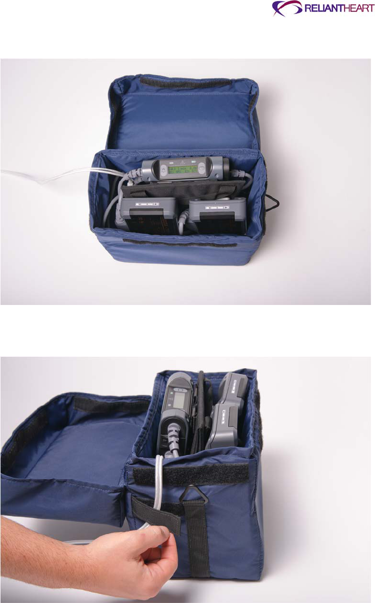
ReliantHeart Confidential – Medical Personnel and Technical Staff 6–7
Figure 6-3. Properly inserting the Controller, battery pockets, batteries, and
cables in the VADPAK Insert into the shower bag
3. Secure the percutaneous cable to the side of the shower bag using the Velcro® strap
attached to the left side of the shower bag.
Figure 6-4. Securing the percutaneous cable to the side of the shower bag
4. Close the lid of the shower bag, and carefully press the sides of the cover inward to
secure the Velcro® fasteners located along each face of the shower bag.
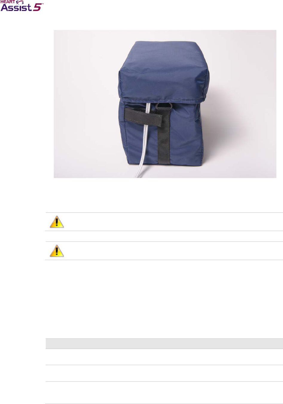
6–8 HeartAssist 5® VAD System Operator's Manual
Figure 6-5. Properly closing and securing the lid of the shower bag
5. When you are finished showering, carefully dry off the outside of the shower bag,
open the top cover of the shower bag, and remove the VADPAK Insert. If water has
leaked into the shower bag, contact ReliantHeart immediately.
Do not use the VADPAK Insert and Controller in the shower bag longer than 30
minutes because the Controller requires air circulation for proper cooling.
Position the shower bag so that it does not tip or drop. Do not allow the
shower bag to sit in liquid.
Activity restrictions
The HeartAssist 5® VAD System allows the patient to move around and be active;
however, there are some restrictions associated with the device. The following tables
describe prohibited activities.
The activities described in Table 6-1 are always prohibited for the patient’s safety and
for the function of the device.
Table 6-1. Prohibited activities
Activity Notes
Total body submersion
(swimming or bathing) Do not submerge the Controller or batteries in water. Submerging
these components can cause the device to malfunction.
Steam bath or dry saunas Do not operate the system in environments where the temperature
is less than 10 °C or greater than 40 °C.
Participation in contact
sports Hard physical contact with other people or objects could damage
the external HeartAssist 5® VAD System hardware, injure internal
organs, or interfere with the tissue healing at the exit site.

ReliantHeart Confidential – Medical Personnel and Technical Staff 6–9
Consult the doctor and gain prior approval before allowing the patient to engage in the
activities described in Table 6-2.
Table 6-2. Restricted activities
Activity Notes
Showering Obtain approval from the doctor. A shower bag is also required.
Driving an automobile Obtain approval from the doctor. In addition, local laws may
prohibit persons in your condition from operating motor vehicles.
Flying Obtain approval from the doctor. In addition, check with the airlines
about possible special requirements.
Non-contact sports
(golfing, jogging, tennis) The patient and his or her doctor can determine whether
participation in a certain sport could cause equipment damage or
bodily harm.
The activities described in Table 6-3 have no known risks.
Table 6-3. Permitted activities
Activity Notes
Careful sponge baths No total submersion
Sexual activity
Housework
Moderate exercise Walking, gardening, cycling, and so forth
Shopping
Caring for the exit site
Change the percutaneous cable exit site dressing daily using strict aseptic technique
(sterile gloves minimally).
1. Gently cleanse the site with a mild disinfectant soap (preferably chlorhexidine
solution).
2. Rinse with sterile normal saline solution.
3. Dry the cleansed site using a sterile 4” x 4” gauze pad.
4. Cover the cleansed and dried site with a dry, sterile dressing.
Do not apply prophylactic topical agents to the exit site wound unless ordered by the
physician.
As you clean the exit site each day, examine it for signs of infection such as the following:
Redness
Swelling
Drainage
Open sores or ulcers
Pain
Skin that is warm to the touch
If any sign of infection or break in the tissue is present, contact the doctor immediately.

6–10 HeartAssist 5® VAD System Operator's Manual
Caring for the percutaneous cable
It is extremely important that the percutaneous cable is protected from extreme or
frequent bending or kinking. Damage to the percutaneous cable, depending on the
degree, can cause the VAD to stop.
Follow these recommendations to reduce damage to the percutaneous cable:
Do not severely bend or kink the percutaneous cable.
Do not let the percutaneous cable become twisted.
Allow for a gentle curve of the percutaneous cable.
Do not severely bend the percutaneous cable multiple times or wrap it tightly.
Keep the percutaneous cable clean. Wipe off any dirt or grime that appears. If
necessary, use a towel with soap and warm water to gently clean the percutaneous
cable. However, never submerge the cable or other system components in water or
liquid.
Do not pull on or move the cable going through the skin.
Be aware of the location of the Controller at all times.
Protect the Controller from falling or from pulling on the percutaneous cable.
Do not allow the percutaneous cable to catch or snag on anything that will pull on or
move the cable.
Check the percutaneous cable daily for signs of damage (such as cuts, holes, or
tears).
Caring for the VADPAK
The VADPAK is an ergonomic storage system that allows the patient to carry the
Controller, battery pockets, and batteries. If the patient is going for a walk, disconnect the
Independent Power Supply or the HeartAttendant®.

ReliantHeart Confidential – Medical Personnel and Technical Staff 7–1
Chapter 7
Equipment Care and Maintenance
In this chapter
Introduction ................................................................................................................................... 7-2
All HeartAssist 5® VAD System components ............................................................................... 7-2
Environmental conditions ................................................................................................. 7-2
Contact with liquids .......................................................................................................... 7-2
Electromagnetic disturbances .......................................................................................... 7-3
Service ............................................................................................................................. 7-4
Controller ....................................................................................................................................... 7-4
LVAD Battery Charger .................................................................................................................. 7-4
Independent Power Supply ........................................................................................................... 7-5

7–2 HeartAssist 5® VAD System Operator's Manual
Introduction
The HeartAssist 5® VAD System is made of tough, durable materials, but it does require
some basic care as described in the following sections. In addition, support team
personnel should perform periodic safety and function checks of your HeartAssist 5®
VAD System equipment.
All HeartAssist 5® VAD System components
The following subsections “Environmental conditions,” “Contact with liquids,”
“Electromagnetic disturbances,” and “Service” apply to all HeartAssist 5® VAD System
components.
Environmental conditions
The HeartAssist 5® VAD System components operate under the following environmental
conditions.
Do not operate the Controller where temperatures are less than -10 °C (14 °F) or
greater than 40 °C (104 °F), or where the relative humidity is non-condensing, less
than 10% Rh or greater than 75% Rh.
Do not operate the Independent Power Supply where temperatures are less than 0 °C
(32 °F) or greater than 40 °C (104 °F) or where the relative humidity is non-
condensing, less than 10% Rh or greater than 75% Rh.
Do not operate the LVAD Battery Charger where temperatures are less than 0 °C (32
°F) or greater than 50 °C (122 °F), or where the relative humidity is non-condensing,
less than 10% Rh or greater than 75% Rh.
Do not store the system in environments where temperatures are less than –20 °C
(–4 F) or greater than 55 °C (131 °F).
Do not expose the batteries to moisture or heat.
Do not expose the Controller, VADPAK, VADPAK Insert, battery pockets, Independent
Power Supply to moisture.
The VADPAK carry bag is flame retardant, but you must be careful when using the
bag near open flame or embers. Any hot item that falls onto or within the bag must be
removed as quickly as possible to prevent scorching or marring of the materials.
The Controller meets the IP32 rating as designated in IEC 60529 Degrees of
protection provided by enclosures. This rating signifies that the Controller case
protects the Controller hardware and software from dripping fluid and solid foreign
objects ≥ 2.5 mm in diameter.
Do not transport the HeartAssist 5® VAD System in environments where
temperatures are less than 0 °C (32 °F) or greater than 55 °C (122 °F).
Travel should be limited to pressure altitude of 0 –2000 m (6500 ft).
The altitude specification does not limit use of the device on fixed wing aircraft, since
commercial planes utilize pressurized cabins. For example, when a plane is traveling
at 35,000 feet altitude, the pressurized altitude inside the cabin is equivalent to 5,400
feet above sea level
Contact with liquids
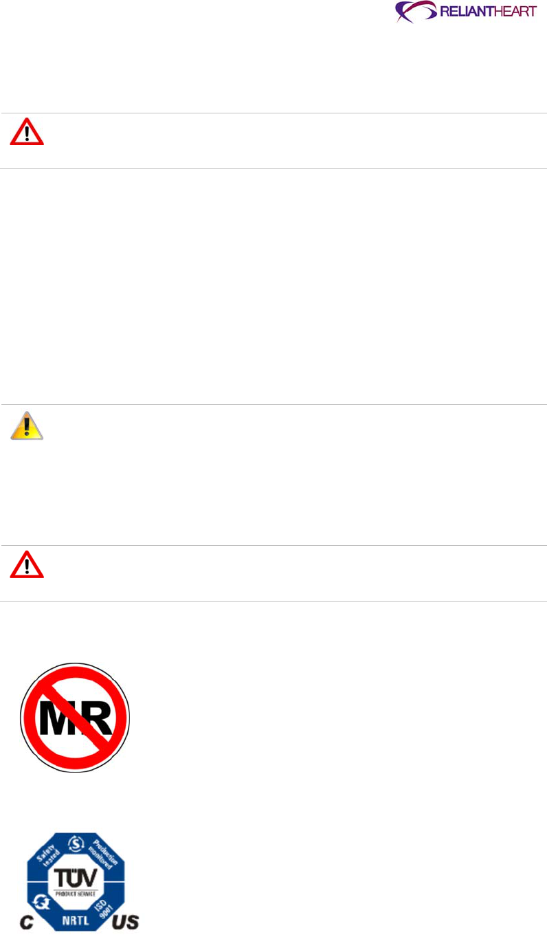
ReliantHeart Confidential – Medical Personnel and Technical Staff 7–3
All HeartAssist 5® VAD System components (with the exception of the shower bag) are
susceptible to damage by liquids. Keep all liquids away from HeartAssist 5® VAD System
components.
Keep all liquids away from equipment to avoid accidental spills. Do not put any
part of this equipment under water or in other liquids. Contact with liquids
increases the risk of electrical shock and of damage to the equipment.
Electromagnetic disturbances
Laboratory testing suggests that patients have little risk from most devices that might
produce electromagnetic disturbances (such as metal detectors, microwave ovens, and
cellular phones). However, such devices can affect electronic equipment at very close
range. For this reason, observe the recommended separation distances in Tables D-1
through D-4 beginning on page D-2 in Appendix D, “Manufacturer guidance for
environmental conditions.”
The HeartAssist 5® VAD has been shown to have acceptable risk regarding
electromagnetic disturbances, as specified by international standard IEC 60601-1-
2:2007.
The system has not been tested with each possible brand of device, and the
possibility of electromagnetic disturbances exists.
If you experience unexpected changes in the speed of the VAD, investigate
potential sources of electromagnetic disturbances (such as cellular phones,
radio transmitters, or microwave ovens) within a few feet. If you discover
disturbances, move away from the potential source, and determine if the VAD
operation returns to normal. If it does not return to normal, contact
ReliantHeart.
Do not subject patients implanted with the VAD to magnetic resonance
imaging (MRI). The VAD contains ferromagnetic components, and MRI can
cause device failure or patient injury.
Figure 7-1. MRI warning and safety seal
MR unsafe
7–4 HeartAssist 5® VAD System Operator's Manual
VAD support equipment was assessed for basic electrical and constructional safety
with respect to IEC/EN 60601-1/A2: 1995
UL2601-1: 1997 (North American Deviations to IEC 60601-1)
UL60601-1: 2003 (HeartAttendant®)
CAN/CSA-C22.2 No. 601.1-M90 (with updates 1 and 2 for HeartAttendant®) Service
Service
There are no user-serviceable parts in the Controller, LVAD Battery Charger,
HeartAttendant® or Independent Power Supply. Contact your support team for service of
this equipment.
Do not service this equipment yourself. Only qualified personnel can service
this equipment. If service is required, contact ReliantHeart.
Do not modify this equipment. No modification of this equipment is allowed.
Do not open the back cover of any ReliantHeart device.
Controller
The Controller does not require routine maintenance. You can wipe dust off of the
surface of the device with a clean, dry, lint-free cloth, and you can clean spills from the
cover with a dampened cloth.
Do not drop the Controller on any hard surface. Dropping the Controller can
damage internal parts causing the device to malfunction.
LVAD Battery Charger
The LVAD Battery Charger does not require routine maintenance. You can wipe dust off
of the surface of the device with a clean, dry, lint-free cloth, and you can clean spills from
the cover with a dampened cloth.
Do not attempt to wipe liquid from the inside of the LVAD Battery Charger
battery bays as this action might bend or otherwise damage the connector
pins.

ReliantHeart Confidential – Medical Personnel and Technical Staff 7–5
Independent Power Supply
The Independent Power Supply does not require routine maintenance. You can wipe dust
off of the surface of the device with a clean, dry, lint-free cloth, and you can clean spills
from the cover with a dampened cloth.

ReliantHeart Confidential – Medical Personnel and Technical Staff 8–1
Chapter 8
Return and Disposal
In this chapter
Introduction ................................................................................................................................... 8-2
Return of components ................................................................................................................... 8-2
HeartAssist 5® VAD ......................................................................................................... 8-2
VAD accessories .............................................................................................................. 8-2
HeartAttendant® .............................................................................................................. 8-2
LVAD Battery Charger ..................................................................................................... 8-2
12-volt batteries ................................................................................................................ 8-3
Disposal ........................................................................................................................................ 8-3

8–2 HeartAssist 5® VAD System Operator's Manual
Introduction
This chapter discusses the procedures necessary to return and dispose of the
HeartAssist 5® VAD System components.
Return of components
If the patient is participating in a clinical trial, ReliantHeart requests the return of all
components of the HeartAssist 5® VAD System to ReliantHeart when the device is
explanted, as described in the following subsections.
HeartAssist 5® VAD
Explant the VAD according to the procedures in “Explanting the VAD” on page 3-26.
Package and return the VAD using the supplied return container. Return the VAD
components to ReliantHeart using an approved Returned Goods Authorization (RGA).
Return the following VAD components:
HeartAssist 5® VAD
Inflow cannula
Outflow graft
Graft protector
Flow probe
Intact sewing ring
Percutaneous cable
VAD accessories
Pack VAD accessories (devices that are used during the operation of the VAD system
and that are in contact with the patient) in the original suitcase supplied, label them
clearly with the patient ID number, and return them to ReliantHeart using an approved
Returned Goods Authorization (RGA). Do not return the HeartAttendant®, 12-volt
batteries, LVAD Battery Charger, or Independent Power Supply.
Return the following devices:
Controllers (primary and backup)
VADPAK
HeartAttendant®
The HeartAttendant® is retained by the center for use with additional patients. If the
HeartAttendant® is no longer needed, contact customer support (see page iii) to arrange
shipping for the unit to ReliantHeart.
LVAD Battery Charger
The LVAD Battery Charger is retained by the center for use with additional patients. If the
LVAD Battery Charger is no longer needed, contact customer support (see page iii) to
arrange shipping for the unit or units to ReliantHeart.

ReliantHeart Confidential – Medical Personnel and Technical Staff 8–3
12-volt batteries
If batteries are part of an ongoing clinical trial, contact customer support (see page iii);
otherwise, dispose of batteries in accordance with Disposal.
Disposal
Follow local governing ordinances and recycling plans regarding disposal or recycling of
non-returnable device components.

ReliantHeart Confidential – Medical Personnel and Technical Staff 9–1
Chapter 9
The HeartAssist 5® LBSA VAD and the Pediatric Patient
In this chapter
Overview ....................................................................................................................................... 9-2
Description .................................................................................................................................... 9-2
Implant .......................................................................................................................................... 9-3
HeartAssist 5® LBSA VAD operation ........................................................................................... 9-3
Alarms ........................................................................................................................................... 9-4
Patient teaching ............................................................................................................................ 9-5
Outside of the hospital .................................................................................................................. 9-5
Infection ......................................................................................................................................... 9-6
Nutrition and hydration .................................................................................................................. 9-6
Anticoagulation .............................................................................................................................. 9-6
Emergencies ................................................................................................................................. 9-7

9–2 HeartAssist 5® VAD System Operator's Manual
Overview
The HeartAssist 5® LBSA VAD is indicated for use to provide temporary left side
mechanical circulatory support as a bridge to cardiac transplantation for pediatric patients
(5-16 years old, with BSA greater than or equal to 0.7 m2 and less than 1.5 m2) who are
in NYHA Class IV end stage heart failure, are refractory to medical therapy and who are
(listed) candidates for cardiac transplantation.
All of the information presented in the HeartAssist 5® VAD System Operator's Manual is
true for the HeartAssist 5® LBSA VAD and the pediatric patient. This section reviews
issues that are specific to the use of the HeartAssist 5® LBSA VAD in pediatric patients.
This section is directed toward the physician-investigator and hospital staff caring for the
HeartAssist 5® LBSA VAD patient.
Persons providing care to pediatric patients who receive this device should read this
entire manual and Chapter 7 of the HeartAssist 5® VAD System Patient Manual before
managing operation of the HeartAssist 5® LBSA VAD in children or adolescents. This
section does not repeat all of the cautions and instructions contained elsewhere in this
manual, and this chapter should not be substituted for reading the entire manual.
Description
The HeartAssist 5® LBSA VAD is essentially the same device as the adult HeartAssist
5® VAD with modifications to enhance fit in the child. The functionality of the HeartAssist
5® LBSA VAD and the HeartAssist 5® VAD are the same in providing adequate blood
flow, so the HeartAssist 5® LBSA VAD is expected to provide clinical benefit in children
with end-stage heart failure. The HeartAssist 5® LBSA VAD has all of the same attributes
as the HeartAssist 5® VAD since the primary differences in the HeartAssist 5® LBSA
VAD are to optimize fit of the device in children.
The following minor modifications have been incorporated into the adult VAD to make the
HeartAssist 5® LBSA VAD:
140° inflow cannula angle
The tighter inflow angle (140o vs. the 115o angle of the adult VAD) allows for better
positioning of the VAD to facilitate the best fit in the pre-peritoneal or thoracic cavity
of the smaller BSA patient.
Shortened graft protector
The function of the flexible graft protector is to assure a smooth bend radius of the
outflow graft and prevent it from kinking. A shorter graft protector is necessary
because the tighter inflow cannula angle positions the pump outflow somewhat closer
to the aorta, thereby decreasing the distance between the pump outflow and the
aorta in smaller-framed patients. The graft protector is shortened to a length that will
facilitate a better fit in a smaller thoracic cavity while not affecting its function.
Shortened inlet cannula
The length of the inflow cannula is shortened by 1 cm to adapt to the smaller
pediatric ventricle.
There are no changes to function or additional safety risks. All ancillary equipment and
accessories for the HeartAssist 5® LBSA VAD are identical to those used in the adult
HeartAssist 5® VAD System.
At locations where both the adult HeartAssist 5® VAD and the HeartAssist 5® LBSA VAD
are being implanted, it is imperative to select the HeartAssist 5® LBSA VAD for children.
The outer packaging for the HeartAssist 5® LBSA VAD is clearly labeled and indicates

ReliantHeart Confidential – Medical Personnel and Technical Staff 9–3
that the VAD is a humanitarian use device. Moreover, the visibility of the pump in its
blister pack allows identification of the tighter inflow cannula angle and the shortened
graft protector.
Implant
The sequence of surgical steps to implant the HeartAssist 5® LBSA VAD is the same as
performed with adult implants. The primary concern for implant in children is achieving
the proper fit of the HeartAssist 5® LBSA VAD in the thoracic cavity. Assess the potential
fit of the HeartAssist 5® LBSA VAD in pediatric patients prior to implant using methods
such as chest x-ray, echocardiogram, or CAT scan. At the time of surgery, fit may be
determined using the anatomical fit pump provided with the implant kit. Once implanted,
the position of the inflow cannula in the ventricle can be evaluated with trans-esophageal
echocardiography and the pump adjusted in the pocket to result in proper position.
Consider the nature of axial flow and each child’s specific cardiac anatomy when
implanting the HeartAssist 5® LBSA VAD. Septal shunts can reduce flow across the
pump and can also be exacerbated by the continuous pumping action of the device.
Certain cardiac anomalies might make it difficult to place the inflow cannula properly, and
when it lies too close to the septum or free wall might result in ventricular collapse. The
potential device-heart interaction for all variations of potential cardiac anomalies in
children is beyond the scope of this discussion and is left to the surgeon’s expertise.
HeartAssist 5® LBSA VAD operation
The HeartAssist 5® LBSA VAD has a flow capacity equivalent to the adult pump that
should be adequate to provide circulatory support in children. The pump can operate
effectively at the range of flows expected for pediatric heart failure patients. When
assessing the suitability of the small child’s flow needs, Figure 6-3 shows the relationship
between speed, flow, and outflow pressure that may be helpful in estimating flow and
speed settings for the child. As with the adult HeartAssist 5® VAD, pump flows can be
adjusted in the HeartAssist 5® LBSA VAD by controlling the pressure gradient across the
pump with perturbations of preload and afterload.
Children are more reactive to neurovascular stimuli such as changes in cardiac output or
the administration of vasoactive drugs. In particular, rapid changes in systemic vascular
resistance (SVR) can be experienced with pediatric patients. Elevated SVR reduces
pump flow by elevating the outflow pressure and increasing resistance across the pump.
In such situations of low flow and increased SVR, treating the elevated SVR could be
superior to altering the pump speed to attain more flow. If a child receives a low flow
alarm, the SVR should be evaluated by checking the patient’s blood pressure. When
frequent low flow alarms occur, consider arranging for home monitoring of the child’s
blood pressure with a Doppler stethoscope if necessary.
The minimum pump speed for the HeartAssist 5® LBSA VAD is 7500 RPM; the VAD
cannot run at a lower speed regardless of the patient’s physiology. Figure 9-1 on page
9-4 depicting the relationship between outlet pressure, pump speed, and flow can be
helpful in determining the speed to set the VAD to achieve the desired flow for a child.
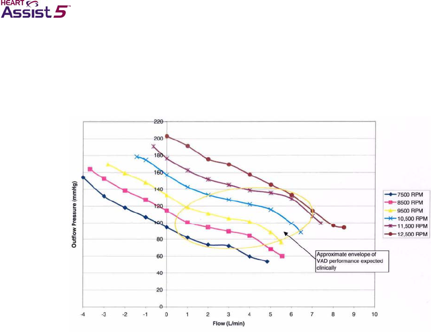
9–4 HeartAssist 5® VAD System Operator's Manual
Figure 9-1. Outlet pressure vs. flow
Initially, set the HeartAssist 5® LBSA VAD speed threshold alarm so that repeated
REDUCED MOTOR SPEED alarms do not occur at the speed required to obtain the
desired pump flow for a child. See “Setting alarm parameter thresholds” on page 5-16.
All ancillary equipment and accessories for the HeartAssist 5® LBSA VAD are identical to
those used in the adult HeartAssist 5® VAD System. There is a slight, but unlikely,
chance that toys that utilize wireless or radio controlled technology might cause
electromagnetic interference with the Controller. Prior to patient discharge to the home,
this possibility should be tested with toys the child frequently uses.
Smaller children might have difficulty changing batteries due to the size and weight of the
batteries. In such cases, caregivers must change batteries for the child at appropriate
intervals or the child should be carefully supervised during battery changes.
The VADPAK containing the Controller and two batteries might be large for the child and
might be heavy for the child to wear. The shoulder strap and waist belt should be
adjusted to fit the child well before the child is discharged to the home. If the weight of the
VADPAK puts pressure on the child’s shoulder, extra padding can be placed beneath the
shoulder strap. In the event that alternate means for wearing the Controller and batteries
must be employed, ensure that the child’s percutaneous cable, Controller and batteries
remain in close proximity to the exit site to avoid stretching or uncoupling of connections.
Alarms
Alarm functions for the HeartAssist 5® LBSA VAD are identical to those used in the adult
HeartAssist 5® VAD System. The alarm threshold for flow might need to be reduced to
avoid low flow alarms in smaller children who may have flows less than 2 L/min. If the
child is old enough, he or she should be taught to react to alarms by seeking help from a

ReliantHeart Confidential – Medical Personnel and Technical Staff 9–5
parent or caregiver. Adolescents can be taught how to resolve diagnostic alarms and
respond to emergency alarms. Children who cannot recognize or respond to alarms
properly should be within hearing distance of a responsible person knowledgeable in the
operation of the HeartAssist 5® LBSA VAD at all times. The significance of emergency
alarms, i.e., PUMP STOPPED, should be communicated to the child with a HeartAssist
5® LBSA VAD.
Patient teaching
Both children and their parents or caregivers should receive training in how to manage
the HeartAssist 5® LBSA VAD system. Parents and caregivers can be trained in a
manner similar to adult HeartAssist 5® VAD patients. Information in the HeartAssist 5®
VAD System Patient User’s Manual must be taught to children using age appropriate
materials that match the child’s attention and comprehension abilities. Information should
be conveyed to children in multiple, short sessions and the child should be allowed to
practice or interact with their device as much as possible. The focus of HeartAssist 5®
LBSA VAD teaching in the pediatric patient should be on making the child an active
participant in his or her care. Special emphasis should be placed on the ability to
recognize and respond to alarms as well as procedures for the child to follow in case of
emergency.
To ensure their safety, children should be taught to understand that the device is life
supporting and that none of the components, especially the Controller, are objects with
which to play. The child will need a sense of the criticality associated with the connection
between the percutaneous cable and the Controller so that he or she will protect it. It is
essential to teach the child and the caregiver how to care for the exit site and how to
avoid situations that might cause the site to get dirty in order to prevent exit site or
driveline infections. As a result of patient teaching efforts, children with the HeartAssist
5® LBSA VAD should become comfortable with the device and know its value to their life,
while at the same time, have no fear of the device.
Children should not be discharged home with the HeartAssist 5® LBSA VAD unless the
parent or caregiver and the child, to the extent possible, have successfully completed
training in the device’s management. Parents or caregivers should be advised to continue
to reinforce teaching with the child while at home. Local emergency services personnel,
the child’s teacher and school nurse, and any other people who will assume a care-giving
role with the child should be given training in the management of the device, alarms, and
emergency procedures when the child is to be discharged.
Outside of the hospital
Before going outside of the hospital, pediatric patients and their parents or caregivers
should be provided with the necessary backup equipment and instructed to carry it.
The HeartAssist 5® VAD System Patient User’s Manual that accompanies The
HeartAssist 5® VAD System Operator's Manual (this book) provides a discussion of
issues that pediatric patients might face with the device during daily operation.
Individuals with a limited ability to care for themselves, including some children, must be
accompanied by a companion knowledgeable in the management of the HeartAssist 5®
VAD System at all times. Older children, who may not always be with a trained
companion, must be well trained in the management of their HeartAssist 5® LBSA VAD
system and able to change batteries as well as respond to alarms on their own. Frequent
close supervision might be necessary for the parent or caregiver and child to ensure that
anticoagulant and other cardiac medications are taken properly and that the exit site is
cared for properly.

9–6 HeartAssist 5® VAD System Operator's Manual
Infection
The small diameter and flexibility of the HeartAssist 5® LBSA VAD percutaneous cable
reduces the potential for infection along the driveline or at the exit site. However, the
driveline tunnel is shorter for children and the external cable is likely to be longer at the
cable’s exit from the body. Both of these factors can increase the impact of any infection
in a child with the HeartAssist 5® LBSA VAD.
Because the cable exiting the child’s body might be longer, it can be subject to increased
movement or damage at the exit site, enhancing the potential for infection. For these
reasons, ReliantHeart recommends that the percutaneous cable be stabilized at the exit
site in children for the first two weeks after implant until good tissue in-growth has
occurred. Tape can be used to secure the cable during this period. Thereafter, the exit
need only to be covered when children are in an environment that has a high likelihood of
getting the exit site dirty (e.g., a sandbox, playing with cars in the dirt, and so forth). Of
course children, parents, and caregivers must be taught proper hygiene for the exit site,
and this hygiene should be emphasized during the patient’s clinic follow-up visits.
Nutrition and hydration
Nutritional needs vary between the adult and child. Physicians should be cognizant of the
varied needs of children and appropriately provide dietary instruction and prescribe
nutritional supplements. It should be kept in mind that as blood flow increases in the child
as a result of VAD support, they may become more active, restore growth processes, and
thus, have dynamic nutritional needs. As in all chronically ill patients, nutrition should
achieve a positive nitrogen balance for the child. A positive nitrogen balance is an
important factor for preventing infection.
Children become dehydrated more rapidly than adults. Dehydration may lead to reduced
left ventricular filling in the child and result in ventricular suction due to the continuous
pumping action of the HeartAssist 5® LBSA VAD. In the adult HeartAssist 5® VAD
experience, hypovolemic perturbations of pump flow have been observed in the early
morning upon awakening. If a child awakes with dizziness or has a flow waveform
consistent with suction, the child should be hydrated during the night when feasible.
Simply, having the child drink a glass of water if he or she wakes up at night might
resolve his or her symptoms of hypovolemia. Parents and caregivers must be careful to
prevent dehydration in children when children are active, particularly in hot environments.
Children also may become critically dehydrated with various viral illnesses. It is very
important to administer appropriate fluids to sick children with the HeartAssist 5® LBSA
VAD early in the course of the virus to maintain proper left ventricular filling and pump
output.
Anticoagulation
Children with the HeartAssist 5® LBSA VAD must be anticoagulated. Coumadin and
aspirin have been used primarily for anticoagulation in the adult HeartAssist 5® VAD
population. However, a child may metabolize drugs more rapidly, and might have a
greater effect from an adult dosage. Anticoagulation experience with implantable VADs in
children is limited. In general, physicians should determine the intensity of anticoagulation
in light of their rapidly changing physiology and their propensity for activity and potential
injury. The exact pharmacologic agents employed for anticoagulation in a child are left to
the discretion of the physician, but in any case, the child should have adequate coverage
for the coagulation cascades as well as for platelet activity.

ReliantHeart Confidential – Medical Personnel and Technical Staff 9–7
Emergencies
An emergency situation can be caused by conditions requiring medical care or by a
mechanical problem that interferes with the pumping ability of the HeartAssist 5® LBSA
VAD. It is important to teach the parent or caregiver and the child how to identify and
respond to an emergency. The most important action is to restore power and function to
the HeartAssist 5® LBSA VAD. Prior to a pediatric patient leaving the hospital, the
hospital staff should provide the child and the parent or caregiver with a card, letter,
bracelet, or other form of medical identification that indicates the child has a left
ventricular assist device. Contact information for the parent or caregiver and the child’s
physician should be included with the medical identification.
Both cardiopulmonary resuscitation (CPR) and cardiac defibrillation may be performed on
the child with a HeartAssist 5® LBSA VAD system. As with the adult HeartAssist 5® VAD
patient, a pulse for the child with a HeartAssist 5® LBSA VAD may not be palpable even
when the pump is operating properly. Parents and caregivers should be instructed not to
perform CPR or cardiac defibrillation if the child is awake and responsive, even if they
cannot feel a pulse.
Children who are too young or unable to respond to device alarms, change batteries or
seek help should always be accompanied by a parent, caregiver, or other individual
knowledgeable in the operation of the HeartAssist 5® LBSA VAD.

ReliantHeart Confidential – Medical Personnel and Technical Staff A–1
Appendix A
Troubleshooting
In this appendix
Controller troubleshooting ............................................................................................................. A-2
Non-VAD related troubleshooting ................................................................................................. A-7
Interpreting suction in analog waveforms ..................................................................................... A-9
HeartAttendant® errors ...............................................................................................................A-12

A–2 HeartAssist 5® VAD System Operator's Manual
Controller troubleshooting
Table A-1 describes troubleshooting for alarm messages displayed on the Controller
LCD. For examples of these messages, see “Emergency alarms” on page B-4 and
“Diagnostic alarms” on page B-6.

ReliantHeart Confidential – Medical Personnel and Technical Staff A–3
Table A-1. Troubleshooting guide for Controller alarms
Alarm or error Associated event Troubleshooting
PUMP STOPPED
alarm The VAD has stopped.
The Controller
automatically tries
restarting nine times within
approximately 60
seconds.
The LCD alternates
between PUMP
STOPPED and PUMP
RESTARTING while
restarting.
You can force the VAD to restart by removing both batteries and
reinserting one battery into a battery pocket while not tethered
to wall power as described in “Manual VAD restart” below.
Check for flashing alarms, which can indicate why the VAD
has stopped. For example: VAD DISCONNECTED.
Check for system damage.
Attempt to verify that an unknown electrical disturbance is
not affecting the Controller by moving to another location.
If the VAD has stopped and the Controller has finished trying to
start nine times, one way to force a restart is as follows:
1. Connect the Controller to the HeartAttendant®.
2. Navigate to the PUMP screen.
See page 5-18.
3. Wait three seconds, then press the Alarm Silence button.
4. Press STOP PUMP, then press START PUMP.
See page 5-18 and page B-4.
Manual VAD restart
If a HeartAttendant® is not available, and the VAD did not
restart, perform the manual restart procedure described below:
1. Disconnect the battery pockets from any external power
source.
2. Briefly remove both batteries from the battery pockets.
3. Re-insert one of the batteries into one of the battery
pockets.
This procedure activates the restart algorithm, which
triggers an additional nine automatic restart attempts.
If the VAD does not restart, continue with step 4.
If the VAD restarts, disregard the remaining steps.
When the VAD restarts, the emergency alarm clears.
4. If the VAD does not restart after you have performed the
manual restart procedure, replace the Controller with the
backup Controller.
5. Contact EMS and ReliantHeart.
The impeller and the motor Controller can
occasionally lose synchronization. When this
event occurs, the LCD displays the PUMP
STOPPED then PUMP RESTARTING alarms,
then it returns to the default display (assuming
no other alarms are present). The audible
emergency alarm does not sound for this
event, but the event memory is captured and
the HeartAttendant® alarm history triggers.
The resynchronization event typically allows
the VAD to stop for approximately two
seconds.
PUMP
RESTARTING
alarm
The VAD is attempting to
restart. 1. See “Diagnostic alarm 4: PUMP RESTARTING” on page B-
8.
2. Contact ReliantHeart.

A–4 HeartAssist 5® VAD System Operator's Manual
Alarm or error Associated event Troubleshooting
REDUCED FLOW
RATE alarm The flow rate measured by
the implanted flow probe
has dropped below the
programmed alarm
threshold.
This alarm does not automatically clear. You must press the
Controller Alarm Silence button.
1. Verify that the VAD is running at the appropriate speed.
See Figure B-2 on page B-2.
2. Attempt fluid consumption.
3. Verify that the flow sensor is enabled.
See “Deactivating the flow sensor” on page 5-16.
4. Verify that the RECEIVED AMPLITUDE on the LCD display
of the Controller or on the PUMP screen of the
HeartAttendant® (Figure 5-18 on page 5-18) is greater than
1.0 volt for both channels A and B.
See Figure B-4 on page B-3.
5. On the Controller or HeartAttendant®, verify that the VAD is
not drawing excess current greater than 16 watts.
See Figure B-2 on page B-2.
6. Contact ReliantHeart.
Even if the VAD appears to be running normally, the patient
must return to the hospital to have the situation diagnosed. The
speed of the VAD must be increased or the flow alarm value
decreased in order to avoid this alarm.
EXCESS
CURRENT alarm The VAD is drawing
current in excess of the
programmed alarm
threshold.
This alarm does not automatically clear. You must press the
Controller Alarm Silence button.
1. Verify that the VAD is still producing flow.
See Figure B-1 on page B-2.
2. Verify that the VAD is running at or near the set VAD
speed.
See Figure B-2 on page B-2.
3. Contact ReliantHeart.
The patient must return to the hospital for one or more EXCESS
CURRENT alarms that cannot be cleared in 10 minutes, or for
recurrent EXCESS CURRENT alarms.
During a restart, the EXCESS CURRENT
alarm can occasionally appear. This condition
is normal because the VAD momentarily uses
high power during a restart.
Fail-safe LED
display frozen The fail-safe LED is lit, the
Controller is emitting a
high-pitched continuous
alarm, the LCD display is
frozen, and the battery
LEDs are lit. The VAD is
running at the last set
speed.
1. Replace the Controller with the backup Controller.
2. Contact ReliantHeart.

ReliantHeart Confidential – Medical Personnel and Technical Staff A–5
Alarm or error Associated event Troubleshooting
No display The LCD is off, the LEDs
are off, and the Controller
is emitting a high-pitched
continuous emergency
alarm.
The Controller has failed
internally. Due to potential
processor failure, no
display is associated with
this alarm.
1. Replace the Controller with the backup Controller
immediately.
2. Contact ReliantHeart.
BOTH
BATTERIES
DISCONNECTED
alarm
Both batteries are
disconnected. 1. Verify that all batteries are fully seated into the battery
pockets.
2. Verify that the battery pocket connectors are correctly
inserted into the Controller connectors.
3. Verify that the battery pocket cables are not cut or
damaged.
4. Verify that at least one of the batteries is charged.
If the emergency alarm clears, the batteries are connected;
disregard further steps.
If the alarm does not silence, continue with step 5.
5. Replace the Controller with the backup Controller.
6. Contact ReliantHeart.
VAD
DISCONNECTED
alarm
The VAD has become
disconnected from the
Controller.
1. Verify that the percutaneous cable is not damaged.
2. Unscrew the white defibrillation cover from the
percutaneous cable.
3. Disconnect the driveline from the percutaneous cable and
verify that the pins inside the VAD connector are straight
and free from debris or liquid.
4. Plug the driveline connector back into the percutaneous
cable ensuring that the driveline connector is fully seated
with the percutaneous cable connector.
If the emergency alarm silences, the VAD is running.
If the VAD does not restart, and the message does not
clear when the Alarm Silence button is pressed, replace the
Controller with the backup Controller.
5. Screw the white defibrillation cover onto the driveline cable.
6. Contact emergency medical services and ReliantHeart.
Continuous
audible alarm The Controller is
malfunctioning. 1. The patient must seek immediate medical assistance if the
VAD has stopped.
2. Replace the Controller with the backup Controller.
3. Contact ReliantHeart.
REDUCED
MOTOR SPEED
alarm
The RPM of the VAD has
fallen below the
programmed alarm
threshold.
1. If the patient experiences dizziness, light-headedness or
other MOTOR SPEED below the programmed alarm
symptoms, he or she must seek medical assistance.
2. Contact ReliantHeart.
BATTERY 1 OR 2
DISCHARGED
alarm
The battery in port 1 or 2
has discharged below
25%.
Replace the discharged battery with a charged battery.

A–6 HeartAssist 5® VAD System Operator's Manual
Alarm or error Associated event Troubleshooting
BATTERY 1 OR 2
DISCONNECTED
alarm
Either battery 1 or 2 has
been disconnected. 1. Verify that the battery is firmly seated into the battery
pocket.
2. Verify the battery plug is properly seated into battery port of
Controller.
3. If alarm does not clear, contact ReliantHeart.
BATTERY 1 OR 2
EXPIRED alarm The battery in port 1 or 2
has discharged below
15%, or the battery
voltage is too low.
1. Replace the expired battery with a charged battery.
2. If the battery expired alarm occurred prior to a battery
discharged alarm for that battery, contact ReliantHeart for a
replacement battery.

ReliantHeart Confidential – Medical Personnel and Technical Staff A–7
Non-VAD related troubleshooting
The following tables describe troubleshooting information for the HeartAssist 5® VAD
System.
Table A-2. Troubleshooting guide for non-VAD issues
Situation or error Troubleshooting
The Controller LCD display is unreadable, the
battery LEDs respond to battery changes, and
the fail-safe mode LED is off.
It is likely that the VAD is still running normally.
1. Verify the functionality of the battery LEDs by inserting and
removing a fully charged battery into one of the battery
ports while the other battery port contains a charged
battery.
If the LCD is not functional but the battery and fail-safe
mode status indicators are still functional and you feel no
adverse effects, the VAD is probably still functioning
correctly.
2. Replace the Controller with the backup Controller.
3. Contact ReliantHeart.
The Controller LCD display is unreadable, the
battery LEDs respond to battery changes, and
the fail-safe mode LED is on (solid red).
It is likely that the VAD is still running in fail-safe
mode at the last set speed. Because the motor
Controller is separate circuitry from the CPU,
the VAD could continue to run in the event of a
Controller failure. However, the circuitry that
verifies the functionality of the CPU detects a
failure in the CPU and sets the motor controller
to the last set speed.
1. Replace the Controller with the backup Controller.
2. Contact ReliantHeart.
The Controller LCD display is unreadable; the
battery LEDs do not respond to battery
changes.
It cannot be determined whether or not the VAD
is operational.
1. Replace the Controller with the backup Controller.
2. Contact ReliantHeart.
The Controller is splashed with liquid. Wipe the liquid from the case of the Controller.
The Controller becomes soiled. Wipe the Controller with a slightly damp cloth with mild
detergent (for example, dishwasher soap).
Never spray water or detergent directly
onto the Controller. Always apply water or
detergent to a soft cloth, wring it out until
just slightly damp, and wipe the Controller.
The Controller becomes submerged in liquid. 1. Replace the Controller with the backup Controller
immediately.
2. Contact ReliantHeart.
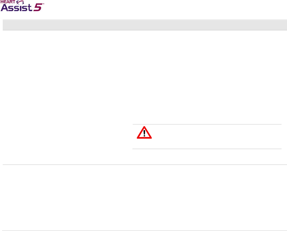
A–8 HeartAssist 5® VAD System Operator's Manual
Situation or error Troubleshooting
A VADPAK with VADPAK Insert is submerged
in liquid. 1. Locate your backup Controller, backup battery pocket, a
charged battery, and the Independent Power Supply.
2. Insert a charged battery into the backup battery pocket.
3. Power up and connect the Independent Power Supply to
the backup battery pocket.
4. Connect the backup battery pocket to the backup
Controller. Perform the Controller replacement with the
backup.
5. Contact ReliantHeart.
If the backup battery pocket and the Independent Power
Supply are not available, do not disconnect the Controller.
Try to drain liquid, and contact ReliantHeart immediately.
The patient must always have extra
batteries, a backup battery pocket, and a
backup Controller.
A battery is submerged in liquid. If the battery is in the battery pocket, replace both the battery
pocket and battery with a backup battery pocket and a spare
battery.
If the battery is not in the battery pocket, do not attempt to use
or recharge this battery.
Do not attempt to use or recharge any battery that becomes
submerged in liquid.
Contact ReliantHeart for a replacement battery and battery
pocket.

ReliantHeart Confidential – Medical Personnel and Technical Staff A–9
Situation or error Troubleshooting
An external power source, such as the
Independent Power Supply (IPS), is connected
to the battery pocket external power connector,
but the power source is not indicated on the
Controller display.
1. Verify that the connector cable is correctly inserted in the
battery pocket connector.
If the Controller display does not indicate that the IPS or
APS is connected, continue with steps 2–5.
2. Using the Controller display, check the battery status for
both battery pocket batteries to ensure adequate charge
levels.
See Figure B-1 on page B-2.
3. With the IPS or APS connected to the battery pocket,
disconnect the battery pocket from the Controller.
See “Disconnecting from the Independent Power Supply”
on page 6-4.
4. Press the Alarm Silence button on the Controller front
panel.
If you do not press the Alarm Silence button on
the Controller front panel, the alarm sounds,
notifying you that it is disconnected.
5. Disconnect the IPS or APS from the battery pocket
connector, and connect the IPS or APS directly into the
Controller connector.
You can damage the connectors if you
force them without proper alignment. Do
not twist the connectors while inserting
them after the connectors are aligned.
If the Controller front panel displays the external power
indicator (a plug symbol), the battery pocket external
power connector is malfunctioning. Replace the battery
pocket with a backup battery pocket, and contact
ReliantHeart for a replacement.
If the Controller front panel is not displaying the external
power indicator, the IPS or APS is malfunctioning.
Reconnect the battery pocket, and contact ReliantHeart
for a replacement IPS or APS.
Interpreting suction in analog waveforms
The VAD generates a change in pressure. A gradient works to draw blood out of a filled
ventricle by creating a low pressure in the VAD’s inflow cannula. Suction refers to a
condition where the VAD cannot draw blood. This condition can be a result of inadequate
filling of the ventricle or partial or complete obstruction of the inflow cannula by some
portion of the myocardium. The result can be a collapse of the ventricular wall with further
reduction in VAD flow. Suction is typically seen with hypovolemia, poor cannula
placement, or poor flow of blood from the right side to the left side. Suction with
ventricular collapse can occur at any time during a patient’s course.
This problem is best resolved by increasing the filling of the left ventricle, by improving
cannula placement, or by decreasing pump speed. As an interim measure, or if the cause
of the suction cannot be identified, the VAD speed can be reduced to relieve the suction
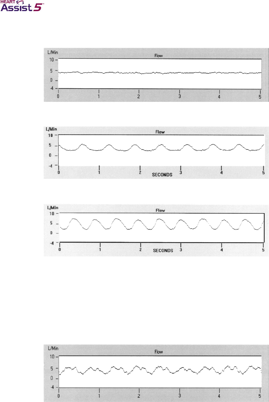
A–10 HeartAssist 5® VAD System Operator's Manual
and resultant ventricular collapse. Figure A-1 shows examples of waveforms without
suction.
Figure A-1. Examples of normal flow with the HeartAssist 5® VAD
A. No pulsatility
B. Pulsatility, low amplitude
B. Pulsatility, high amplitude
As shown in Figure A-2, the presence of suction creates unique flow wave forms that can
be identified by a “double hump” at the end of the systolic phase of the pulse or, in the
case of the non-pulsatile ventricle, sharp, sudden downward slopes. The physician
should be consulted when suction occurs to decide if the patient’s blood volume needs to
be increased or some other therapy is necessary to provide more blood to the ventricle
prior to changing speed. Only immediately decrease the speed in cases of severe
suction.
Figure A-2. Examples of excess suction with the HeartAssist 5® VAD
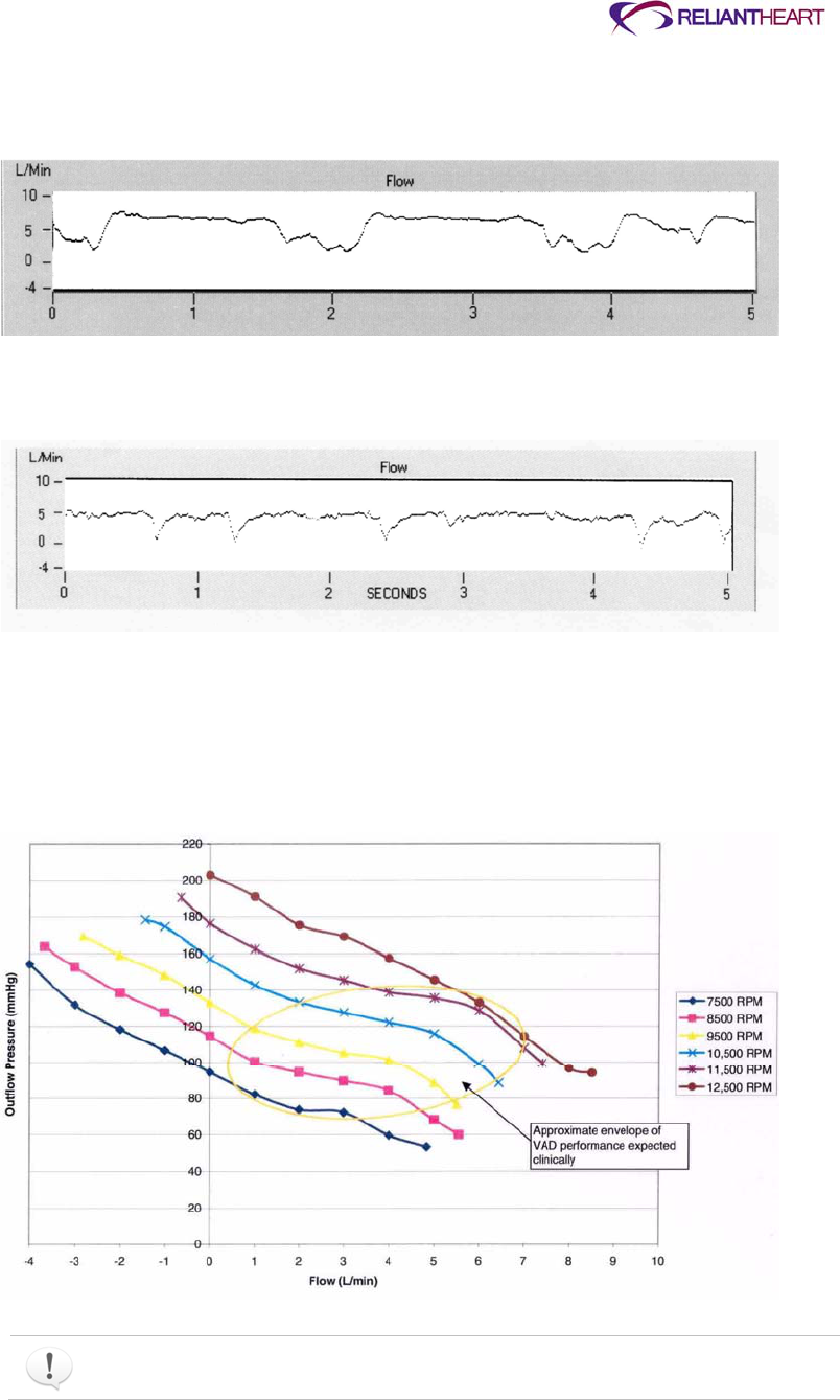
ReliantHeart Confidential – Medical Personnel and Technical Staff A–11
A. Suction with ventricular function – produces erratic wave form with multiple
peaks
B. Suction with no native ventricular function
C. Suction with no native ventricular function - produces sharp downward
gradients in flow
You can use Figure A-3 to estimate flow through the VAD.
Figure A-3. HeartAssist 5® VAD characterization outlet pressure vs. flow
The table in Figure A-3 was generated using a water and glycerin mix.

A–12 HeartAssist 5® VAD System Operator's Manual
HeartAttendant® errors
Table A-3 contains HeartAttendant® troubleshooting information.
Table A-3. Troubleshooting guide for the HeartAttendant®
Event or Error Troubleshooting
The HeartAttendant® will not turn on 1. Check the power connection at the wall.
2. Check the power cord connection on the back of the
HeartAttendant®.
3. Check the fuse of the HeartAttendant®. (See “Verifying local
mains voltage” on page 5-28.)
4. Call technical support.
The HeartAttendant® software “locks up” or
becomes nonresponsive 1. Wait 45 seconds for the software to reset automatically.
2. If problem persists, disconnect the VADPAK from the
HeartAttendant® first, then unplug and re-plug the
HeartAttendant® power cord from the wall.
3. Call technical support.
Battery status icons fail to illuminate when a
battery is placed in battery charging
compartments.
1. Ensure that the battery is inserted correctly with the connector
side facing up.
2. Check for and clear any dirt from the battery connector.
3. If the battery was exposed to cold temperatures, allow the
battery to warm to room temperature before charging.
4. Call technical support.
The fan sound is reduced, and the
HeartAttendant® is warm. Call technical support.

ReliantHeart Confidential – Medical Personnel and Technical Staff B–1
Appendix B
Controller Messages and Alarms
In this appendix
Standard message screens .......................................................................................................... B-2
Emergency alarms ........................................................................................................................ B-4
Emergency alarm 1: PUMP STOPPED ........................................................................... B-4
Emergency alarm 2: BOTH BATTERIES DISCONNECTED ........................................... B-5
Emergency alarm 3: VAD DISCONNECTED .................................................................. B-6
Diagnostic alarms .......................................................................................................................... B-6
Diagnostic alarm 1: EXCESS CURRENT ........................................................................ B-6
Diagnostic alarm 2: REDUCED FLOW RATE ................................................................. B-7
Diagnostic alarm 3: REDUCED MOTOR SPEED ............................................................ B-7
Diagnostic alarm 4: PUMP RESTARTING ...................................................................... B-8
Diagnostic alarm 5: BATTERY 1 DISCONNECTED ........................................................ B-8
Diagnostic alarm 6: BATTERY 1 DISCHARGED ............................................................ B-9
Diagnostic alarm 7: BATTERY 1 EXPIRED ...................................................................B-10
Diagnostic alarm 8: BATTERY 2 DISCONNECTED ......................................................B-10
Diagnostic alarm 9: BATTERY 2 DISCHARGED ..........................................................B-11
Diagnostic alarm 10: BATTERY 2 EXPIRED .................................................................B-11
Controller failure alarms ..............................................................................................................B-12
Controller failure alarm 1: fail-safe alarm .......................................................................B-12
Controller failure alarm 2: Controller failure alarm .........................................................B-12
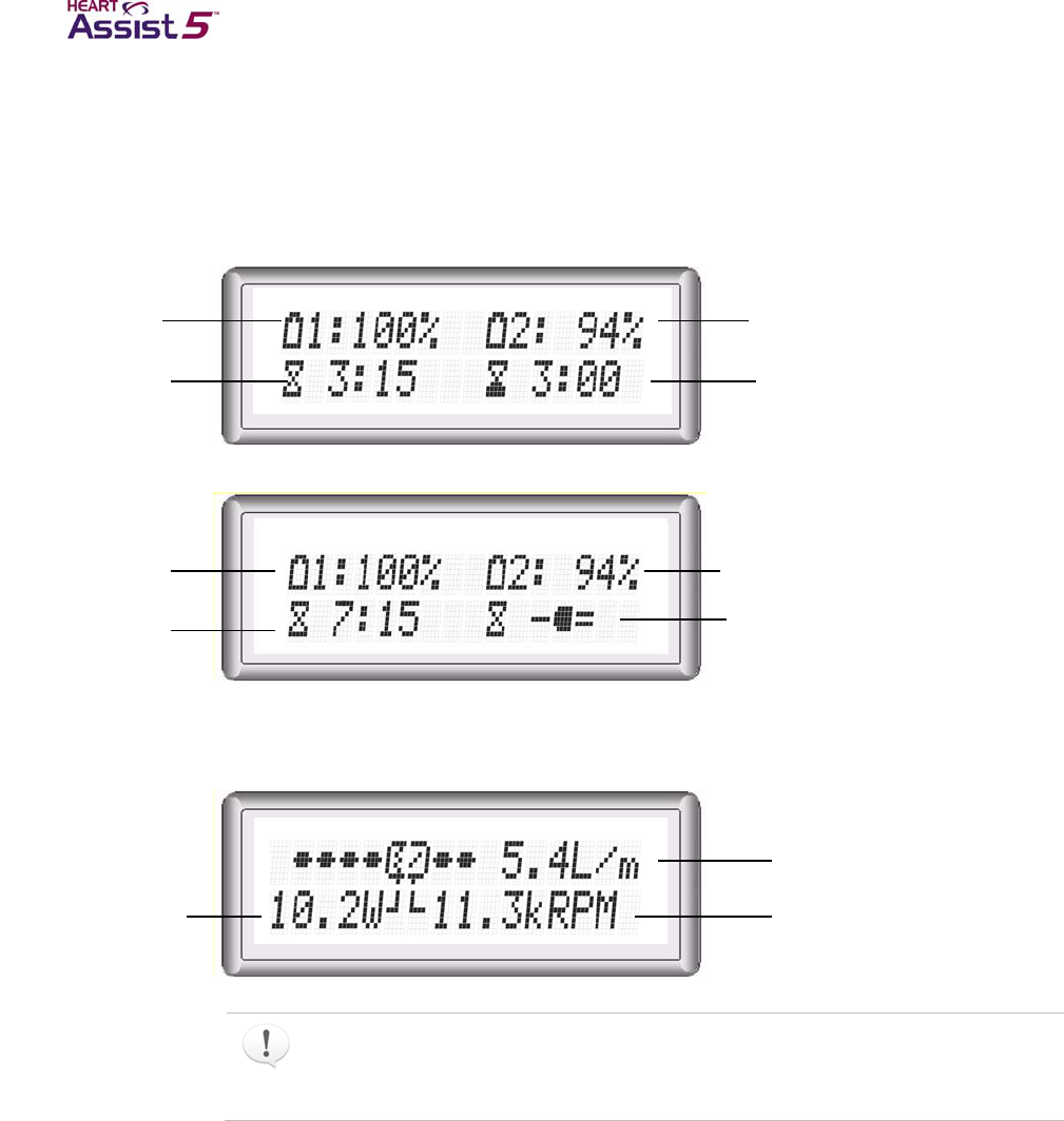
B–2 HeartAssist 5® VAD System Operator's Manual
Standard message screens
The Controller has seven standard message screens that continuously display
information while scrolling with the Scroll Display button.
Figures B-1 through B-6 display the seven messages shown on the Controller.
Figure B-1. Standard message screen 1: battery status
Using battery power
Using external power
Figure B-2. Standard message screen 2: current VAD parameters
When the system is plugged in to external AC or DC power (for example with the
Independent Power Supply), the battery charge time remaining that is displayed in
standard message screen 1 is replaced by the external power indicator (a plug
symbol), as shown in Figure B-1.
Battery 2 Percent
Charge Remaining
Battery 2 Charge Time
Remaining hh:mm
Battery 1 Percent
Charge Remaining
Battery 1 Charge Time
Remaining hh:mm
Battery 2 Percent
Charge Remaining
Battery 2 External
Power Indicator
Battery 1 Percent
Charge Remaining
Battery 1 Charge Time
Remaining hh:mm
VAD Motor Power in
WATTS, 0 – 24 W
Flow rate in liters per
minute
VAD Speed (kRPM) 7.5 kRPM to
12.5 kRPM
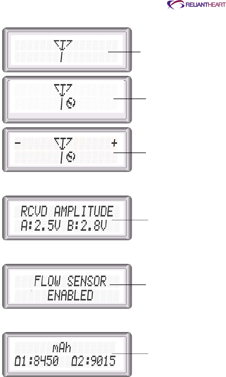
ReliantHeart Confidential – Medical Personnel and Technical Staff B–3
Figure B-3. Standard message screen 3: wireless antenna status
Figure B-4. Standard message screen 4: flow probe received amplitude
Figure B-5. Standard message screen 5: flow sensor status
Figure B-6. Standard message screen 6: battery capacity
Wireless Antenna Enabled
Wireless Antenna Disabled
Wireless Antenna Disabled with
Adjust Controls
Flow Probe Received Amplitude:
A & B Channels 1 - 5 Volts
Flow Probe/Meter ENABLED or
DISABLED
Battery 1 and 2 Capacity
Remaining in Milliamp Hours
(mAh)
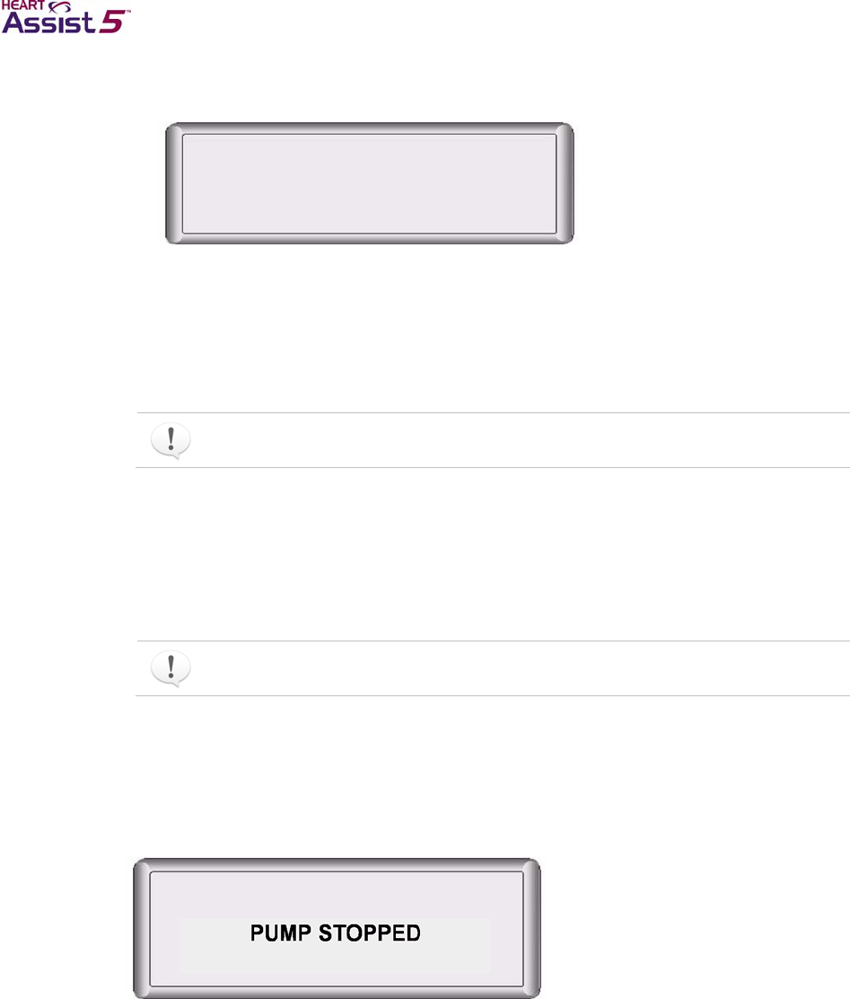
B–4 HeartAssist 5® VAD System Operator's Manual
Figure B-7. Standard message screen 7: not used
Emergency alarms
The following subsections describe emergency alarms. See “Emergency alarms” on page
4-4 for an explanation of these alarms.
The Controller indicates an emergency alarm with a fast, loud, two-tone ringing
sound.
Emergency alarm 1: PUMP STOPPED
The VAD has stopped. The Controller immediately activates the restart algorithm for
approximately 60 seconds. The LCD alternates between PUMP STOPPED and PUMP
RESTARTING while the restart algorithm is activated.
If the pump successfully restarts, the emergency alarm automatically clears.
Example
Figure B-8 displays an example of emergency alarm 1, PUMP STOPPED. This alarm
indicates that the VAD is not running.
Figure B-8. Emergency alarm 1: PUMP STOPPED
User response
If the PUMP STOPPED alarm displays, take the following actions:
1. Allow the automatic restart algorithm to complete its cycle (within 60 seconds).
2. If the VAD does not restart automatically after 60 seconds, perform the following
manual restart procedure:
a. Disconnect the battery pockets from any external power sources (such as the
Independent Power Supply).

ReliantHeart Confidential – Medical Personnel and Technical Staff B–5
b. Briefly remove both batteries from the battery pockets.
c. Re-insert one of the batteries into one of the battery pockets.
This procedure activates the restart algorithm, which triggers an additional nine
automatic restart attempts.
3. If the VAD does not restart after performing the manual restart procedure, replace the
Controller with the backup Controller.
4. Contact ReliantHeart immediately.
Emergency alarm 2: BOTH BATTERIES DISCONNECTED
The Controller is not receiving power from either of the batteries.
Example
Figure B-9 displays an example of emergency alarm 2, BOTH BATTERIES
DISCONNECTED.
This alarm indicates that either the batteries are not properly inserted in the battery
pockets, the cables connecting the battery pockets and Controller are not secure or are
damaged, or that the Controller is malfunctioning. The VAD is not running when this
alarm is present.
Figure B-9. Emergency alarm 2: BOTH BATTERIES DISCONNECTED
User response
If the BOTH BATTERIES DISCONNECTED alarm displays, take the following actions:
1. Confirm that both batteries are properly inserted into the battery pockets.
2. Verify all cable connections.
3. If the VAD does not start, and the alarm does not clear automatically, replace the
Controller with the backup Controller.
See “Controller replacement” on page 4-6.
This alarm clears automatically when the VAD restarts.
A Controller that is not receiving power alarms for approximately three minutes. This
alarm cannot be silenced.
BOTH BATTERIES
DISCONNECTED

B–6 HeartAssist 5® VAD System Operator's Manual
Emergency alarm 3: VAD DISCONNECTED
The VAD is not connected to the Controller.
Example
Figure B-10 displays an example of emergency alarm 3, VAD DISCONNECTED. This
alarm indicates that the VAD is not running and is not connected to the Controller.
Figure B-10. Emergency alarm 3: VAD DISCONNECTED
User response
If the VAD DISCONNECTED alarm displays, take the following actions:
1. Unscrew the white defibrillation cover from the driveline cable.
2. Verify and, if necessary, reconnect the driveline cable to the Controller.
See “Connecting the percutaneous cable to the Controller” on page 3-18.
3. Verify that the VAD has restarted successfully.
4. If VAD does not restart, and the alarm does not clear automatically, replace the
Controller with the backup Controller.
See “Controller replacement” on page 4-6.
5. Contact ReliantHeart immediately.
Diagnostic alarms
The following subsections describe diagnostic alarms. See “Diagnostic Alarms on page
4-4 for an explanation of these alarms.
The Controller indicates a diagnostic alarm with a slow beeping sound.
Diagnostic alarm 1: EXCESS CURRENT
The VAD is drawing current in excess of the programmed alarm threshold.
This alarm does not silence or clear automatically. Press the Controller Alarm
Silence button to clear this alarm.
VAD
DISCONNECTED
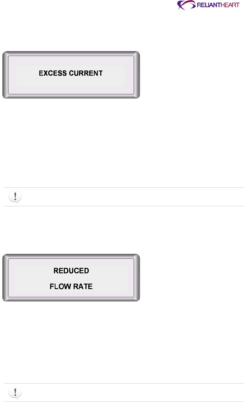
ReliantHeart Confidential – Medical Personnel and Technical Staff B–7
Example
Figure B-11 displays an example of diagnostic alarm 1, EXCESS CURRENT.
Figure B-11. Diagnostic alarm 1: EXCESS CURRENT
User response
If the EXCESS CURRENT alarm displays, contact ReliantHeart immediately.
Diagnostic alarm 2: REDUCED FLOW RATE
The flow rate measured by the implanted flow probe has decreased below the
programmed alarm threshold.
This alarm does not silence or clear automatically. Press the Controller Alarm
Silence button to clear this alarm.
Example
Figure B-12 displays an example of diagnostic alarm 2, REDUCED FLOW RATE.
Figure B-12. Diagnostic alarm 2: REDUCED FLOW RATE
User response
If the REDUCED FLOW RATE alarm displays, contact ReliantHeart immediately.
Diagnostic alarm 3: REDUCED MOTOR SPEED
The speed (RPM) of the VAD has fallen below the programmed alarm threshold.
This alarm does not clear automatically. Press the Alarm Silence button to clear this
alarm.

B–8 HeartAssist 5® VAD System Operator's Manual
Example
Figure B-13 displays an example of diagnostic alarm 3, REDUCED MOTOR SPEED.
Figure B-13. Diagnostic alarm 3: REDUCED MOTOR SPEED
User response
If the REDUCED MOTOR SPEED alarm displays, contact ReliantHeart immediately.
Diagnostic alarm 4: PUMP RESTARTING
The VAD has stopped and is attempting to restart. The message PUMP RESTARTING
displays briefly during the restart attempt alternating with the PUMP STOPPED message.
Example
Figure B-14 displays an example of diagnostic alarm 4, PUMP RESTARTING.
Figure B-14. Diagnostic alarm 4: PUMP RESTARTING
User response
If the PUMP RESTARTING alarm displays, take the following actions:
1. Every two to three seconds, press the Alarm Silence button on the Controller, and
verify that the flow rate, RPM, and power are normal.
See Figure B-2 on page B-2. If the alarm silences, the VAD has restarted
successfully.
2. Contact ReliantHeart immediately.
Diagnostic alarm 5: BATTERY 1 DISCONNECTED
Battery 1 is disconnected from the battery pocket as indicated on the Controller with a
blinking amber light and an audible diagnostic alarm.
Example
Figure B-15 displays an example of diagnostic alarm 5: BATTERY 1 DISCONNECTED.
REDUCED
MOTOR SPEED
PUMP
RESTARTING

ReliantHeart Confidential – Medical Personnel and Technical Staff B–9
Figure B-15. Diagnostic alarm 5: BATTERY 1 DISCONNECTED
User response
If the BATTERY 1 DISCONNECTED alarm displays, take the following actions:
1. Verify that the battery is firmly seated into battery pocket 1.
See “Charging a battery” on page 4-26
2. Verify that the battery pocket connector is firmly inserted into the Controller connector
for battery 1. This alarm clears automatically after you reconnect battery 1.
See “Connecting a battery pocket to the Controller” on page 4-24. This alarm clears
automatically after you reconnect battery 1.
3. If alarm does not clear, contact ReliantHeart.
Diagnostic alarm 6: BATTERY 1 DISCHARGED
The battery plugged into battery pocket 1 has discharged below a 25% charge level, as
indicated on both the Controller and the battery pocket with a blinking amber light and an
audible diagnostic alarm.
Example
Figure B-16 displays an example of diagnostic alarm 6, BATTERY 1 DISCHARGED.
Figure B-16. Diagnostic alarm 6: BATTERY 1 DISCHARGED
User response
If the BATTERY 1 DISCHARGED alarm displays, take the following actions:
1. Replace the battery in battery pocket 1 with a fully charged battery.
See “Charging a battery” on page 4-26.
2. Recharge the discharged battery.
This alarm clears automatically when you replace the discharged battery with a charged
battery.
BATTERY 1
DISCONNECTED
BATTERY 1
DISCHARGED

B–10 HeartAssist 5® VAD System Operator's Manual
Diagnostic alarm 7: BATTERY 1 EXPIRED
The battery plugged into battery pocket 1 has discharged below 15%, or its voltage is too
low, as indicated on both the Controller and battery pocket with a blinking amber light and
an audible diagnostic alarm.
Example
Figure B-17 displays an example of diagnostic alarm 7, BATTERY 1 EXPIRED.
Figure B-17. Diagnostic alarm 7: BATTERY 1 EXPIRED
User response
If the BATTERY 1 EXPIRED alarm displays, take the following actions:
1. Replace the expired battery in battery pocket 1 with a fully charged battery.
See “Charging a battery” on page 4-26.
2. Recharge the expired battery.
This alarm clears automatically after you replace the expired battery with a charged
battery.
Diagnostic alarm 8: BATTERY 2 DISCONNECTED
Battery 2 is disconnected from the battery pocket as indicated on the Controller with a
blinking amber light and an audible diagnostic alarm.
Example
Figure B-18 displays an example of diagnostic alarm 8, BATTERY 2 DISCONNECTED.
Figure B-18. Diagnostic alarm 8: BATTERY 2 DISCONNECTED
User response
If the BATTERY 2 DISCONNECTED alarm displays, take the following actions:
1. Verify that the battery is firmly seated into battery pocket 2.
See “Charging a battery” on page 4-26.
2. Verify that the battery pocket connector is firmly inserted into the Controller connector
for battery 2.
BATTERY 1
EXPIRED
BATTERY 2
DISCONNECTED

ReliantHeart Confidential – Medical Personnel and Technical Staff B–11
This alarm clears automatically after you reconnect battery 2.
Diagnostic alarm 9: BATTERY 2 DISCHARGED
The battery plugged into battery pocket 2 has discharged below a 25% charge level, as
indicated on both the Controller and the battery pocket with a blinking amber light and an
audible diagnostic alarm.
Example
Figure B-19 displays an example of diagnostic alarm 9, BATTERY 2 DISCHARGED.
Figure B-19. Diagnostic alarm 9: BATTERY 2 DISCHARGED
User response
If the BATTERY 2 DISCHARGED alarm displays, take the following actions:
1. Replace the battery in battery pocket 2 with a fully charged battery.
See “Charging a battery” on page 4-26.
2. Recharge the discharged battery.
This alarm clears automatically when you replace the discharged battery with a
charged battery.
Diagnostic alarm 10: BATTERY 2 EXPIRED
The battery plugged into battery pocket 2 has discharged below 15%, or its voltage is too
low, as indicated on both the Controller and the battery pocket with a blinking amber light
and an audible diagnostic alarm.
Example
Figure B-20 displays an example of diagnostic alarm 10: BATTERY 2 EXPIRED.
Figure B-20. Diagnostic alarm 10: BATTERY 2 EXPIRED
BATTRY 2
DISCHARGED
BATTERY 2
EXPIRED

B–12 HeartAssist 5® VAD System Operator's Manual
User response
If the BATTERY 2 EXPIRED alarm displays, take the following actions:
1. Replace the expired battery in battery pocket 2 with a fully charged battery.
See “Charging a battery” on page 4-26.Recharge the expired battery.
This alarm clears automatically when you replace the expired battery with a charged
battery.
Controller failure alarms
The following section describes alarms that occur when the Controller ceases to function.
Controller failure alarms are indicated by a continuous tone.
Controller failure alarm 1: fail-safe alarm
The fail-safe LED is lit solid red, a high-pitch continuous alarm sounds, the LCD display is
frozen, and battery LEDs are lit. The VAD continues to run at the last set speed.
Example
When this alarm sounds, the Controller continues to display the same screen that was
present when the fail-safe alarm began to sound.
Figure B-21. Controller failure alarm 1: fail-safe alarm (display frozen)
User response
1. Replace the Controller with the backup Controller.
See “Controller replacement” on page 4-.6
2. Notify your support team of this event, and request a Controller replacement.
Controller failure alarm 2: Controller failure alarm
The LCD is off, the LEDs are off, and the Controller emits a high-pitch continuous alarm
(not a beeping alarm). The Controller has failed internally. The VAD has stopped.
Example
Figure B-22 displays an example of the Controller failure alarm. The Controller has a
blank display when emitting this alarm.
FLOW SENSOR
ENABLED

ReliantHeart Confidential – Medical Personnel and Technical Staff B–13
Figure B-22. Controller failure alarm 2: (no display)
User response
1. Replace the Controller with the backup Controller immediately.
See “Controller replacement” on page 4-6.
2. Notify ReliantHeart of this event immediately, and request a Controller replacement.

ReliantHeart Confidential – Medical Personnel and Technical Staff C–1
Appendix C
System Specifications
In this appendix
Introduction .................................................................................................................................. C-2
HeartAssist 5® VAD specifications .............................................................................................. C-2
Controller specifications ............................................................................................................... C-3
General specifications ..................................................................................................... C-3
Interface features ............................................................................................................ C-3
Safety features ................................................................................................................ C-3
Wireless antenna specifications ................................................................................................... C-4
HeartAttendant® specifications .................................................................................................... C-4
General specifications ..................................................................................................... C-4
Safety features ................................................................................................................ C-4
Electrical specifications ................................................................................................... C-4
Replacement and accessory part list (fuses) .................................................................. C-5
VADPAK and VADPAK Insert specifications ............................................................................... C-5
Independent Power Supply .......................................................................................................... C-5
General specifications ..................................................................................................... C-5
Safety features ................................................................................................................ C-5
Electrical specifications ................................................................................................... C-6
Lithium ion battery ........................................................................................................................ C-6
General specifications ..................................................................................................... C-6
Safety features ................................................................................................................ C-6
Electrical specifications ................................................................................................... C-6
LVAD Battery Charger ................................................................................................................. C-7
General specifications ..................................................................................................... C-7
Electrical specifications ................................................................................................... C-7
Connecter cables, power cords, and fuses .................................................................................. C-7
Essential performance of the HeartAssist 5® VAD ...................................................................... C-7
C–2 HeartAssist 5® VAD System Operator's Manual
Introduction
This chapter presents information on the specifications for the HeartAssist 5® VAD
System components. This chapter also presents information on the use of connecter
cables and power cords, the proper replacement of fuses, and the essential performance
of the HeartAssist 5® VAD.
The service life of the Controller and all accessories is three years.
HeartAssist 5® VAD specifications
Table C-1 describes the general specifications of the HeartAssist 5® VAD.
Table C-1. HeartAssist 5® VAD general specifications
General property Specific property Specification
Weight (without cannula) 92 grams
Size 30 mm x 76 mm
Material VAD and internal components Titanium
Bearings Ceramic
Graft Vascutek Gel Weave
®
(with titanium ring)
Flow probe Titanium, polyurethane, epoxy, polycarbonate
polyurethane
Percutaneous cable Polycarbonate-polyurethane
Graft protector Ultra-high molecular-weight polyethylene
Flow accuracy ±10% when flow > 3 L/min; 0.3 L/min when flow is
< 3 L/min
Range –4.0 L/min to 10.0 L/min

ReliantHeart Confidential – Medical Personnel and Technical Staff C–3
Controller specifications
The following subsections describe the properties of the Controller.
General specifications
Table C-2 describes the general specifications of the Controller.
Table C-2. Controller general specifications
Property Specification
Classification Internally powered, type CF, defibrillation proof
Ingress protection IP32
Weight 2.7 kg (6 lbs) – (with two battery pockets & two batteries)
Dimensions 16.5 cm x 8.9 cm x 5.1 cm
(6.5 in x 3.5 in x 2.0 in)
Programmed pump speed 7500 (±200) to 12500 (±200) RPM
Battery type Lithium Ion (Li-ON)
Power required Range: 0 – 40 W ±10%
Alarm sound pressure 60 – 80 db
Interface features
Patients, caregivers, and support staff use the Controller by interacting with the following
features. See Figure 4-2, “Controller front panel,” on page 4-3 for an example of the
Controller front panel interface.
Battery indicators
Fail-safe and emergency mode indicator LED
LCD display
Programmable language
Real-time clock
Alarm Silence button
Scroll Display button
Battery status indicators
Safety features
The Controller includes the following features to ensure patient safety.
Automatic fail-safe and emergency mode LED (with status)
Automatic pump restart algorithm
Automatic diagnostic tests at start-up
Diagnostic visual and audible alarms
Emergency visual and audible alarms
Built-in data acquisition
Patient information stored in nonvolatile memory

C–4 HeartAssist 5® VAD System Operator's Manual
Wireless antenna specifications
You can use the wireless antenna in all markets where Quadband GSM (850/900/
1800/1900 MHz) is available.
The wireless transmission of data is not a requirement for the Controller to fulfill its
intended use or to meet its indications for use.
HeartAttendant® specifications
The following subsections describe the HeartAttendant® properties.
General specifications
Table C-3 describes the general specifications of the HeartAttendant®.
Table C-3. HeartAttendant® general specifications
Property Specification
Weight 11.34 kg (25 lbs)
Dimensions 55.88 cm x 48.25 cm x 45.72 cm (22 in x 19 in x 18 in)
External indicators LED display
External control Touch screen
Safety features
The HeartAttendant® includes the following features to ensure patient safety.
Fault tolerant operating system
5,000 volt defibrillation protection
Password protection to VAD controls and operating system
Electrical specifications
Table C-4 describes the HeartAttendant® electrical specifications.
Table C-4. HeartAttendant® electrical specifications
Property Specification
Input voltage 120/240 VAC 60/50 Hz
Maximum current 3.0/1.5 A
Equipment type Type CF, defibrillation proof, Class 1
EMI/RFI Class A device
Operation Continuous duty

ReliantHeart Confidential – Medical Personnel and Technical Staff C–5
Replacement and accessory part list (fuses)
Table C-5 lists the HeartAttendant® replacement and accessory parts and their part
numbers. See “Connecter cables, power cords, and fuses” for instructions on obtaining
replacement fuses.
Table C-5. HeartAttendant® part list
Part description Part number
Fuse (US) 5 x 20 mm 120 V / 4 AMP slow blow
Fuse (Europe) 5 x 20 mm 240 V / 3 AMP slow blow
VADPAK and VADPAK Insert specifications
Table C-6 describes VADPAK and VADPAK Insert properties.
Table C-6. VADPAK specifications
Property Specification
VADPAK Bag
Weight 1.81 kg (4.0 lb) (with batteries, battery pockets and controller)
Dimensions 27.94 cm x 10.16 cm x 21.59 cm (11 in x 4.0 in x 8.5 in)
Materials Cordura 500D Black, Cordura 500D Foliage, Soft Tex Skid
Resistant
VADPAK Insert
Weight 1.81 kg (4 lb) (with batteries, battery pockets and controller)
Dimensions 25.4 cm x 20.32 cm x 17.78 cm (10 in x 8 in x 7 in)
Materials Cordura 500D Black, 0.125 Corrugated Plastic
Independent Power Supply
The following subsections describe the Independent Power Supply properties.
General specifications
Table C-7 describes the general properties of the Independent Power Supply.
Table C-7. Independent Power Supply general specifications
Property Specification
Weight 0.45 kg (1 lb)
Dimensions 4.80 cm × 12.07 cm × 7.62 cm (1.89 in × 4.75 in × 3.00 in)
External indicators Power indicator light (green LED)
Ingress protection IPX1
Safety features
The Independent Power Supply includes output protection from short circuit and overload
to ensure patient safety.

C–6 HeartAssist 5® VAD System Operator's Manual
Electrical specifications
Table C-8 describes the Independent Power Supply electrical specifications.
Table C-8. Independent Power Supply electrical specifications
Property Specification
Input voltage 90-264 VAC; 47-63 Hz; 60 W
Maximum voltage 13.5 Vdc; 4.3 A
Equipment type Type CF; Defibrillation proof; Class 1
EMI/RFI Class B device
Operation Continuous duty
Lithium ion battery
The following subsections describe the lithium ion battery properties.
General specifications
Table C-9 describes the general properties of the lithium ion battery.
Table C-9. Lithium ion battery general specifications
Property Specification
Weight 0.45 kg (1 lb)
Dimensions 14.05 cm × 8.86 cm × 2.00 cm (5.53 in × 3.49 in × 0.79 in)
External indicators LED indicator icon (fuel gauge)
Charge percentage Range: 0 – 100% ±10%
Charge time remaining Range: 0:00 – 7:30 hours ±10%
Battery capacity Range: 6000a – 7800 mAh ±10%
a Recommended battery replacement level specified by ReliantHeart.
Safety features
The lithium ion battery includes a discharge cutoff of 9.0 V to ensure patient safety.
Electrical specifications
Table C-10 describes the lithium ion battery electrical specifications.
Table C-10. Lithium ion battery electrical specifications
Property Specification
Input voltage 10.8 V
Maximum voltage 4000 mA (under 30 °C)
3000 mA (over 30 °C)
Equipment type Type BF
Operation Continuous duty

ReliantHeart Confidential – Medical Personnel and Technical Staff C–7
LVAD Battery Charger
The following subsections describe the LVAD Battery Charger properties.
General specifications
Table C-11 describes the general properties of the LVAD Battery Charger.
Table C-11. LVAD Battery Charger general specifications
Property Specification
Weight 0.71 kg (1.56 lb)
Dimensions 17.15 cm × 11.05 cm × 5.03 cm (6.75 in × 4.35 in × 1.98 in)
External indicators LED indicators (green and amber)
External control Recalibration button
Electrical specifications
Table C-12 describes the LVAD Battery Charger electrical specifications.
Table C-12. LVAD Battery Charger electrical specifications
Property Specification
Input voltage 18 VDC
Maximum current 1.8 A
Equipment type Type BF, Class III
EMI/RFI Class III
Operation Intermittent duty
Connecter cables, power cords, and fuses
Only use ReliantHeart-supplied power cords and connecter cables with the HeartAssist
5® VAD System. Contact ReliantHeart to obtain the proper replacement power cords or
connecter cables for your geographical area.
Ensure appropriate fuse usage by obtaining replacement fuses from ReliantHeart. See
“Customer support” on page iii for contact information. See “Replacing fuses” on page 5-
28 for fuse replacement instructions.
Essential performance of the HeartAssist 5® VAD
The HeartAssist 5® VAD operates, without stoppage, at the preset speed. See
“Presetting VAD speed” on page 5-16 for more information.

ReliantHeart Confidential – Medical Personnel and Technical Staff D–1
Appendix D
Manufacturer Guidance for Environmental Conditions
In this appendix
Introduction .................................................................................................................................. D-2
Electromagnetic emissions .......................................................................................................... D-2
Electromagnetic immunity ............................................................................................................ D-2
Recommended separation distance between portable and mobile RF communications
equipment and the Controller, HeartAttendant®, battery pockets, Independent Power
Supply, and batteries ............................................................................................................. D-5
Requirements applicable to ME EQUIPMENT and ME SYSTEMS that
intentionally receive RF electromagnetic energy for the purpose of their
operation (60601-1-2, 5.2.2.5) .................................................................................. D-6
Requirements applicable to ME EQUIPMENT and ME SYSTEMS that include RF
transmitters (60601-1-2, 5.2.2.6) .............................................................................. D-7
FCC statements ........................................................................................................................... D-8
Statement according to FCC part 15.19 ......................................................................... D-8
Statement according to FCC part 15.21 ......................................................................... D-8
Statement according to FCC part 15.105 ....................................................................... D-8
R&TTE Declaration of Conformity ................................................................................................ D-9

D–2 HeartAssist 5® VAD System Operator's Manual
Introduction
The following sections outline the ReliantHeart manufacturer’s guidance and declarations
for the components of the HeartAssist 5® VAD System.
Electromagnetic emissions
The HeartAssist 5® Controller, HeartAttendant®, battery pockets, batteries, Independent
Power Supply, and Controller connector cable are intended for use in the electromagnetic
environment specified in Table D-1. The customer or the user of these components must
ensure that they are used in such an environment.
Table D-1. Electromagnetic emissions guidance and manufacturer’s declaration for all ME
equipment and ME systems
Emissions test Compliance Electromagnetic environment—guidance
RF emissions
CISPR 11
Group 1 These components use RF energy only for their internal
functions. Therefore, RF emissions are very low and are not
likely to cause any interference in nearby electronic equipment.
RF emissions
CISPR 11
Class B These components are suitable for use in all establishments,
including domestic establishments and those directly connected
to the public low-voltage power supply network that supplies
buildings used for domestic purposes.
Harmonic emissions
IEC 61000-3-2
Class A
Voltage fluctuations/flicker
emissions
IEC 61000-3-3
Complies
Electromagnetic immunity
The Controller, HeartAttendant®, battery pockets, batteries, Independent Power Supply
and Controller connector cable are intended for use in the electromagnetic environment
specified in Table D-2 and Table D-3. The customer or the user of these components
must ensure that they are used in such an environment.
Table D-2. Electromagnetic immunity guidance and manufacturer’s declaration for all ME
equipment and ME systems
Immunity test IEC 60601 test
level Compliance Electromagnetic environment—guidance
Electrostatic
discharge (ESD)
IEC 61000-4-2
±6 kV contact
±8 kV air
±6 kV contact
±15 kV air
The relative humidity should be at least 10%.
Electrical fast
transient/ burst
IEC 61000-4-4
±2 kV for power
supply lines
±1 kV for input/
output lines
±2 kV for power
supply lines
±1 kV for input/
output lines
Mains power quality should be that of a typical
commercial or hospital environment.
Surge
IEC 61000-4-5
±1 kV line(s) to
line(s)
±2 kV line(s) to
earth
±1 kV differential
mode
±2 kV common
mode
Mains power quality should be that of a typical
commercial or hospital environment.

ReliantHeart Confidential – Medical Personnel and Technical Staff D–3
Immunity test IEC 60601 test
level Compliance Electromagnetic environment—guidance
Voltage dips,
short
interruptions, and
voltage variations
on power supply
input lines
IEC 61000-4-11
<5% U
Ta
(>95% dip in U
T
)
for 0.5 cycles
40% U
T
(60% dip in U
T
)
for 5 cycles
70% U
T
(30% dip in U
T
)
<5% U
T
(>95% dip in U
T
)
for 5 sec
<5% U
T
(>95% dip in U
T
)
for 0.5 cycles
40% U
T
(60% dip in U
T
)
for 5 cycles
70% U
T
(30% dip in U
T
)
for 25 cycles
<5% U
T
(>95% dip in U
T
)
for 5 sec
Mains power quality should be that of a typical
commercial or hospital environment. If the user of
this equipment requires continued operation during
power mains interruptions, ReliantHeart
recommends powering this equipment from an
uninterruptible power supply (UPS) or a battery.
Power frequency
(50/60 Hz)
magnetic field
IEC 61000-4-8
10 A/m 60 A/m Based on the compliance level of 60 A/m for power
frequency magnetic field, the appropriate
separation distance can be calculated based upon
the current in the power risers using the following
formula:
r =
Where I is the maximum current in amperes in the
mains cable, and r is the recommended minimum
separation distance (in meters).
An example for calculating the separation distance
for a 100 power bus would be as follows:
r =
In the example above, the recommended
separation distance would be about 27 cm.
a U
T
is the AC mains voltage prior to application of the test level.
Table D-3. < Radio Frequency Susceptibility (Radiated and Conducted)
and Electrostatic Discharge >
Heading Heading Heading
Immunity Test RTCA/DO 160F Test Level Com[pliance
Radiated Susceptibility
RTCA/DO-160F Section 20
20V/m 100 to 400 MHz Yes
Radiated Susceptibility
RTCA/DO-160F section 20
150V/m 400 MHz to 8 GHz Yes
Air Discharge
RTCA/DO-160F Section 25
15kV Yes
Compliance indicates that the device did not malfunction while subjected to the listed
test levels.
D–4 HeartAssist 5® VAD System Operator's Manual
Table D-4. Electromagnetic immunity guidance and manufacturer’s declaration for all life
supporting ME equipment and ME systems
Immunity test IEC 60601 test
level Compliance Electromagnetic environment—guidance
Portable and mobile RF communications equipment
should be used no closer to any part of this
equipment, including cables, than the
recommended separation distance calculated from
the equation applicable to the frequency of the
transmitter.
Conducted RF
IEC 61000-4-6
3 Vrms
150 kHz to 80 MHz
Outside ISM bands
a
3 V Recommended Separation Distance
1.2
√
10 Vrms
150 kHz to 80 MHz
in ISM bands
a
10 V Recommended Separation Distance
1.2
√
Radiated RF
IEC 61000-4-3
10 V/ m
80 MHz to 2.5 GHz
10 V/ m
80 MHz to 400
MHz
Recommended Separation Distance: 80 MHz to
400 MHz
1.2
√
20 V/ m
400 MHz to 3.5
GHz
Recommended Separation Distance: 400 MHz to
800 MHz
1.2
√
Recommended Separation Distance: 800 MHz to
3.5 GHz
0.6
√
Recommended Separation Distance: 800 MHz to
3.5 GHz
1.2
√
Where P is the maximum output power rating of the
transmitter in watts (W) according to the transmitter
manufacturer, and d is the recommended
separation distance in meters (m).
b
Field strengths from fixed RF transmitters, as
determined by an electromagnetic site survey
c
;
should be less than the compliance level in each
frequency range
d
.
Interference can occur in the vicinity of equipment
marked with the following symbol:
a The ISM (industrial, scientific, and medical) bands between 150 kHz and 80 MHz are 6,765 MHz to 6,795
MHz; 13,553 MHz to 13,567 MHz; 27,957 MHz to 27,283 MHz; and 40.66 MHz to 40.70 MHz.
b The compliance levels in the ISM frequency bands between 150 kHz and 80 MHz and in the frequency range
80 MHz to 2.5 GHz are intended to decrease the likelihood that mobile/portable communications equipment
could cause interference if it is inadvertently brought into patient areas. For this reason, an additional factor of
10/3 is used in calculating the recommended separation distance for transmitters in these frequency ranges.
ReliantHeart Confidential – Medical Personnel and Technical Staff D–5
Immunity test IEC 60601 test
level Compliance Electromagnetic environment—guidance
c No accurate theoretical prediction of field strength from fixed transmitters such as base stations for radio,
cellular and cordless telephones, land mobile radios, amateur radios, AM and FM radio broadcasts, and TV
broadcasts is possible. To assess the electromagnetic environment due to fixed RF transmitters, consider an
electromagnetic site survey. If the measured field strength in the location in which this equipment is used
exceeds the applicable RF compliance level listed in Table D-3, observe the equipment to verify normal
operation. If you observe abnormal performance, additional measures might be necessary, such as
reorienting or relocating this equipment.
d Over the frequency range 150 kHz to 80 MHz, field strengths should be less than 10 V/m.
At 400 MHz and 800 MHz, the higher frequency range applies.
These guidelines might not apply in all situations. Electromagnetic propagation is
affected by absorption and reflection from structures, objects, and people.
Recommended separation distance between portable and mobile RF
communications equipment and the Controller, HeartAttendant
®,
battery pockets, Independent Power Supply, and batteries
This equipment is intended for use in an electromagnetic environment in which radiated
RF disturbances are controlled. The customer or the user of this equipment can help
prevent electromagnetic interference by maintaining a minimum distance between
portable and mobile communications equipment (transmitters) and this equipment as
recommended in Table D-4, according to the maximum output power of the
communications equipment.
Table D-5. Recommended separation distance between portable and mobile RF
communications equipment and the life-supporting ME equipment and ME
systems
Separation distance according to frequency of transmitter
m
Rated maximum
output power of
transmitter
150 kHz to 80
MHz outside
ISM bands
150 kHz to 80
MHz in ISM
bands
80 MHz to 400
MHz 400 MHz to 800
MHz 800 MHz to 3.5
GHz
W .
√
.
√
.
√
.
√
.
√
0.01 0.12 0.12 0.12 0.06 0.12
0.1 0.38 0.38 0.38 0.19 0.38
1 1.2 1.2 1.2 0.6 1.2
10 3.8 3.8 3.8 1.9 3.8
100 12 12 12 6 12
For transmitters rated at a maximum output power not listed above, the recommended
separation distance d in meters (m) can be determined using the equation applicable to

D–6 HeartAssist 5® VAD System Operator's Manual
the frequency transmitter, where P is the maximum output power rating of the transmitter
in watts (W) according to the transmitter manufacturer.
At 400 MHz and 800 MHz, the separation distance for the higher frequency range
applies.
The ISM (industrial, scientific and medical) bands between 150 kHz and 80 MHz are
6,765 MHz to 6,795 MHz; 13,553 MHz to 13,567 MHz; 26,957 MHz to 27,283 MHz;
and 40.66 MHz to 40.70 MHz.
An additional factor of 10/3 has been incorporated into the formula used in
calculating the recommended separation distance for transmitters in the ISM
frequency bands between 150 kHz and 80 MHz and in the frequency range 80 MHz
to 2.5 GHz to decrease the likelihood that mobile or portable communications
equipment could cause interference if it is inadvertently brought into patient areas.
These guidelines might not apply in all situations. Electromagnetic propagation is
affected by absorption and reflection from structures, objects, and people.
The HeartAttendant® is intended for use in an electromagnetic environment in
which radiated RF disturbances are controlled. The user of the
HeartAttendant® can help prevent electromagnetic interference by maintaining
a minimum distance between portable and mobile RF communications
equipment (transmitters) and the HeartAttendant® as recommended in Table
D-4, according to the maximum output power of the communications
equipment.
Use of equipment and supplies other than those specified in this manual or
sold by ReliantHeart for replacement parts could affect the electromagnetic
compatibility of the HeartAssist 5® VAD with other devices, resulting in
potential interference between the HeartAssist 5® VAD and other devices.
The HeartAttendant® must be kept at least one foot away from electrical
appliances (such as kitchen appliances).
Requirements applicable to ME EQUIPMENT and ME SYSTEMS that intentionally
receive RF electromagnetic energy for the purpose of their operation (60601-1-2,
5.2.2.5)
For ME EQUIPMENT and ME SYSTEMS that intentionally receive FR electromagnetic
energy for the purpose of their operation, the ACCOMPANYING DOCUMENTS shall
include the following information:
a. Each frequency or frequency band of reception; the preferred frequency or
frequency band, if applicable, and the bandwidth of the receiving section of the
ME EQUIPMENT or ME SYSTEM in those bands.
The conquest controller may receive the following frequency ranges:
869.2 MHz to 894.2 MHz

ReliantHeart Confidential – Medical Personnel and Technical Staff D–7
935 MHz to 960 MHz
1805.2 MHz to 1879.8 MHz
1930.2 MHz to 1989.8 MHz
For operation in North America, the conquest controller will be fitted with an antenna
which is optimized to receive frequencies in the GSM 850 and GSM 1900 frequency
bands which have a range of 869.2 to 894.2 MHz and 1930.2 to 1989.8 MHz.
Use of equipment and supplies other than those specified in this manual or sold by
ReliantHeart for replacement parts could affect the electromagnetic compatibility
of the HeartAssist 5® VAD with other devices, resulting in potential interference
between the HeartAssist 5® VAD and other devices.
Requirements applicable to ME EQUIPMENT and ME SYSTEMS that include RF
transmitters (60601-1-2, 5.2.2.6)
For (Conquest Controller) ME EQUIPMENT and (VAD System) ME SYSTEMS that
include RF transmitters, the ACCOMPANYING DOCUMENTS shall include each
frequency or frequency band of transmission, the type and frequency characteristics of
the modulation and the EFFECTIVE RADIATED POWER.
RF Power Output 850MHz band
Limit: FCC: Nominal Peak Output Power < 38.45 dBm (7W)
IC: Nominal Peak Output Power < 40.60 dBm (11.5W) GSM Cellular 850 (GMSK Mode)
Frequency (MHz) Radiated Power ERP (dBm)
824.2 30.5
836.6 31.2
848.8 30.3
RF Power Output 1900MHz band
Limit: Nominal Peak Output Power < 33 dBm (2W) GSM PCS 1900 (GMSK Mode)
Frequency (MHz) Radiated Power EIRP (dBm)
1850.2 29.1
1880.0 29.3
1909.8 27.7
The HeartAssist 5® VAD System has been tested and found to comply with IEC 60601-1-
2:2007 Medical Electrical Equipment - Part 1-2 General Requirements for Safety -
Collateral Standard: Electromagnetic Compatibility. This testing shows the device
provides reasonable protection against interference in a typical medical installation.
The HeartAssist 5® VAD can generate, use, and radiate radio frequency energy and, if
not installed and used in accordance with the instructions, can cause interference to
other devices in the vicinity. However, there is no guarantee that interference will not
occur in a particular installation. If this equipment does cause interference to other
devices or is negatively impacted by other devices, the user is encouraged to attempt to
correct the interference by one or more of the following measures:
Reorient or relocate devices.
Increase the separation between devices.

D–8 HeartAssist 5® VAD System Operator's Manual
Connect the equipment to an outlet on a different circuit.
Consult the manufacturer or technical support engineer for help.
The HeartAssist 5® VAD System requires special precautions regarding
electromagnetic compatibility (EMC), and you must install it and put it into
service according to the EMC information provided in this appendix.
Portable and mobile RF communications equipment can affect the HeartAssist
5® VAD System.
FCC statements
ReliantHeart has issued the following statements regarding the HeartAssist 5® VAD
System wireless transmitter.
The following FCC statements apply to Model: CTL001
FCC ID: 2AB4ZCTL001.
Statement according to FCC part 15.19
This device complies with Part 15 of the FCC Rules. Operation is subject to the following
two conditions: (1) this device may not cause harmful interference, and (2) this device
must accept any interference received, including interference that may cause undesired
operation.
Statement according to FCC part 15.21
Modifications not expressly approved by, ReliantHeart could void the user’s authority to
operate the equipment.
Statement according to FCC part 15.105
This equipment has been tested and found to comply with the limits for a Class B
digital device, pursuant to Part 15 of the FCC Rules. These limits are designed to
provide reasonable protection against harmful interference in a residential
installation. This equipment generates, uses and can radiate radio frequency energy
and, if not installed and used in accordance with the instructions, may cause harmful
interference to radio communications. However, there is no guarantee that
interference will not occur in a particular installation. If this equipment does cause
harmful interference to radio or television reception, which can be determined by
turning the equipment off and on, the user is encouraged to try to correct the
interference by one or more of the following measures:
Reorient or relocate the receiving antenna.
Increase the separation between the equipment and receiver.
Connect the equipment into an outlet on a circuit different from that to which the
receiver is connected.
Consult the dealer or an experienced radio/TV technician for help.

ReliantHeart Confidential – Medical Personnel and Technical Staff D–9
Radio frequency radiation exposure information:
This phone has been tested and meets the FCC RF exposure guidelines for body
worn operations with zero distance. It shall be used with the ReliantHeart
accessories supplied or designated for this product and as documented within this
manual. Use of other accessories may not ensure compliance with the FCC RF
exposure guidelines.
R&TTE Declaration of Conformity
Hereby, ReliantHeart declares that the Controller is in compliance with the essential
requirements and other relevant provisions of Directive 1999/5/EC.
To obtain an English copy of the Declaration of Conformity, write to the address below:
ReliantHeart
8965 Interchange Drive
Houston, TX 77054

ReliantHeart Confidential – Medical Personnel and Technical Staff Glossary 1
Glossary
Anticoagulants
Non habit-forming medications that keep existing blood clots from growing larger as well
as prevents the formation of new blood clots. Heparin is an example.
Aorta
The large arterial trunk that carries blood from the heart to be distributed by branch
arteries through the body.
Aortic regurgitation (“leaky” aortic valve)
The diastolic flow of blood from the aorta into the left ventricle. Regurgitation is caused by
incompetence of the aortic valve or any disturbance of the valvular apparatus (e.g.,
leaflets, annulus of the aorta) resulting in diastolic flow of blood into the left ventricular
chamber.
Aortic valve
A valve with 3 cusps between the left ventricle and the aorta.
Apex
Blunt rounded end of the heart, directed downward, forward, and to the left.
Arrhythmias
Problems that affect the electrical system of the heart, producing abnormal heart
rhythms. They can cause the heart to pump less effectively.
Arterial blood pressure
The pressure of the circulating blood on the arteries.
Arteries
The thick, muscular tubes that carry blood away from the heart.
Atrium
An upper chamber of the heart. Right atrium receives unoxygenated blood from the body.
Left atrium receives oxygenated blood from the lungs.
Cannula
Tube that connects the heart and blood vessels to the pump.
Cardiopulmonary resuscitation (CPR)
An emergency first aid protocol for an unconscious person on whom neither breathing
nor pulse can be detected.

2 Glossary HeartAssist 5® VAD System Operator's Manual
Cardiovascular
Pertaining to the heart and blood vessels.
CE-mark
The approval of manufacturing and quality systems identified with the ISO 9001
certification. This label allows a medical device company to commercialize products in
Europe.
Centrifugal pump technology
As blood is drawn into the pump, a paddle wheel like component (impeller) forces the
blood toward the outside walls and expels it through an opening.
Class IV heart failure
End stage heart failure in which an individual is unable to carry out any physical activity
without discomfort. Symptoms of cardiac insufficiency at rest. If any physical activity is
undertaken, discomfort is increased. In order to determine the best course of therapy,
physicians often assess the stage of heart failure according to the New York Heart
Association (NYHA) functional classification system. This system relates symptoms to
everyday activities and the patient's quality of life.
Coagulation
1. a. The process of becoming viscous, jellylike, or solid; especially the change from a
liquid to a thickened curd-like state not by evaporation but by chemical reaction:
the spontaneous coagulation of freshly drawn blood
the coagulation of egg albumen by heat
b. The process by which such change of state takes place consisting of the alteration
of a soluble substance (as a protein) into an insoluble form or of the flocculation or
separation of colloidal or suspended matter.
2. A substance or body formed by coagulation. There are three systems that are
involved in the coagulation process:
platelets
pro-coagulant system
fibrinolytic system
In artificial heart or ventricular assist device implantation it is necessary to achieve a new
equilibrium among these systems.
Connector
The end of a HeartAssist 5® VAD System component cable. Connectors join HeartAssist
5® VAD System component together. Connectors are universal across the HeartAssist
5® VAD System and join using the same method.
Controller
The Controller regulates the speed and supply of power to the VAD, displays current
operating parameters, and provides visual and audible alarms. The Controller includes
two battery cables and one driveline cable for the VAD connection.

ReliantHeart Confidential – Medical Personnel and Technical Staff Glossary 3
Console
The part of a circulatory support system that drives the blood pumps, thus allowing the
blood to flow through its normal cycle. The console is powered by electricity and has a
back-up battery.
Coronary artery disease (CAD)
Conditions such as atherosclerosis which cause narrowing of the coronary arteries
resulting in decreased blood flow to the heart muscle.
Coronary heart disease (CHD)
A disease in which plaque deposits containing cholesterol atherosclerosis and fat
globules are deposited within the arteries.
Driveline
The driveline consists of a double cable that extends from the implanted LVAD, through
the skin, to the external environment. After emerging from the body, the driveline is often
referred to as the percutaneous cable, and the lead terminates at an electric connector
that attaches to the Controller.
Echocardiography
One of the most important non-invasive techniques used in the diagnosis of heart
disease. This technique allows for the visualization of abnormal valve function or
contraction of the cardiac walls and can also be used to measure ejection fraction.
Echocardiograms are obtained by reflecting high frequency sound waves (ultrasound) off
various structures of the heart, then translating the reflected waves into one and two-
dimensional images.
Embolization
The therapeutic introduction of various substances into the circulation to occlude vessels,
either to arrest or prevent hemorrhaging, to devitalize a structure, tumor, or organ by
occluding its blood supply, or to reduce blood flow to an arteriovenous malformation.
External power indicator
A plug symbol that display on the Controller screen when the HeartAssist 5® VAD
System is connected to an external power source (such as the Independent Power
Supply).
Extubated
To remove a tube from a hollow organ or passageway, often from the airway. The
opposite of extubate is intubate.
Heart chambers
The four sections of the heart through which blood is pumped. The two upper chambers
are called the left atrium and right atrium. The two lower chambers are the left and right
ventricles. Oxygen-rich blood from the lungs enters the left atrium, while oxygen-depleted
blood from the rest of the body flows into the right atrium. Both atria simultaneously pump
blood into the ventricles. The ventricles then pump the blood to the lungs (from right
ventricle) and to the rest of the body (from the left ventricle).

4 Glossary HeartAssist 5® VAD System Operator's Manual
Heart failure
Almost always a chronic, long-term condition, although it can sometimes develop
suddenly. This condition might affect the right side, the left side, or both sides of the
heart. As the heart’s pumping action is lost, blood might back up into other areas of the
body, including: the liver, the gastrointestinal tract and extremities (right-sided heart
failure), the lungs (left-sided heart failure). Class 4 heart failure is the condition when a
patient is exhausted, short of breath or fatigued when just sitting still or lying down in bed.
Heart rate (HR)
The number of beats per minute (avg: 72 beats/min).
Hemoglobin
Protein in red blood cells that transports oxygen. The mean range is 14.5-15.5 g/dL.
Hemolysis
Defined as plasma-free hemoglobin of greater than 50 mg for more than 12 hours.
Associated with systemic hypertension, this condition is usually resolved by reducing the
driving pressure in combination with anti-hypertensive agents.
Hemorrhage
Bleeding; an escape of the blood through ruptured or unruptured vessel walls.
Hemostasis
The prevention of blood loss; a complex process that changes blood from a fluid to a
solid state. Intact blood vessels are central to moderating blood's tendency to clot. The
endothelial cells of intact vessels prevent thrombus formation by secreting tissue
plasminogen activator (t-PA) and by inactivating thrombin and adenosine diphosphate
(ADP). Injury to vessels overwhelms these protective mechanisms and hemostasis
ensues. Hemostasis proceeds in two phases: primary and secondary hemostasis.
Heparin
A highly sulfated glycosaminoglycan widely used as an injectable anticoagulant. Heparin
acts via binding to as an anti-thrombin thereby preventing consequent thrombus
formation; it also enhances activity of lipoprotein lipases. It is also used to form an inner
anticoagulant surface on various experimental and medical devices such as test tubes
and renal dialysis machines. Pharmaceutical grade heparin is commonly derived from the
tissue of slaughter house animals, e.g. porcine intestine or bovine lung.
Hepatic function or failure
Liver function. Fulminant hepatic failure (FHF) is usually defined as the severe
impairment of hepatic functions in the absence of preexisting liver disease.
Impeller
A propulsion device that draws liquid in and forces it through an opening.
LVAD
Left ventricular assist device.

ReliantHeart Confidential – Medical Personnel and Technical Staff Glossary 5
Left atrium
Receives oxygen enriched blood from the lungs and passes it on to the left ventricle.
Left ventricle
One of the two bottom chambers in the human heart. It receives oxygenated blood from
the left atrium via the mitral valve, and pumps it into the aorta via the aortic valve. It forms
a small part of the sternocostal surface and a considerable part of the diaphragmatic
surface of the heart; it also forms the apex of the heart.
Left ventricular assist device (LVAD)
A mechanical pump that is surgically implanted and is used to aid the natural pumping
action of the heart's left ventricle. This device is sometimes called a “bridge to transplant”
because it buys time until a heart transplant can be performed.
Left ventricular assist system
A class of medical devices that helps the left side of the heart pump oxygen-rich blood
through the body. Also called a Left Ventricular Assist Device.
Mains power
General-purpose alternating current (AC) electric power supply.
Mechanical circulatory support
A uni- or bi- ventricular device used to treat patients with advanced heart failure. A
mechanical pump is surgically implanted to provide pulsatile or non-pulsatile flow of blood
to supplement or replace the blood flow generated by the native heart. Types of
circulatory support pumps include pneumatic and electromagnetic pumps. Rotary pumps
are also available.
Mediastinal infections
Acute bacterial infection of the mediastinum. Such infections can evoke a devastating
disease which, in its fulminating form, is often unresponsive to the best therapeutic
efforts. However, if mediastinitis is diagnosed before it reaches the morbid pathological
state, appropriate antibiotic therapy and well-planned surgical intervention might
favorably alter the prognosis.
Mitral valve
Bicuspid valve, left atrioventricular valve: a valve in the heart located in the opening
between the left atrium and the left ventricle, prevents the blood in the ventricle from
returning to the atrium, and consists of two triangular flaps attached at their bases to the
fibrous ring which surrounds the opening and connected at their margins with the
ventricular walls by the chordae tendineae and papillary muscles.
Myocardial infarction
Damage or death of myocardial tissue (heart muscle) of blood flow to the area.
Myocardial revascularization
Restoring blood flow to the myocardium (heart muscle).

6 Glossary HeartAssist 5® VAD System Operator's Manual
Myocarditis
Inflammation of the heart muscle brought on by a virus or bacteria, which might even
result from allergic reaction.
Myocardium
The middle muscular layer of the heart wall. The myocardium is responsible for the
heart’s pumping action and contracts to pump blood out of the heart, and then relaxes as
the heart refills with returning blood. The myocardium is the layer that has the largest
oxygen need and is most affected by decreased blood flow (ischemia).
Occlusion
Venous or arterial occlusion is a state of being closed or shut.
Percutaneous
Passed through the skin.
Perfusion
Blood flow.
Perfusion pressure
The difference between the arterial and venous pressures through an organ or capillary
bed.
Perfusion scan
A test to determine blood flow through the vessels to the heart.
Pericardial cavity
The potential space formed between the two layers of serous pericardium around the
heart. Normally, it contains a small amount of serous fluid that acts to reduce surface
tension and lubricate. Therefore, the cavity facilitates the free movement of the heart. The
cavity surrounds the heart and is continuous with it at all but the points of entry and exit of
great vessels.
Pericardium
The thin outer covering sac (membrane) that surrounds the heart and the roots of the
great blood vessels.
Plasma
The liquid portion of the blood.
Pulmonary artery
The artery which carries blood away from the heart and extends from the right ventricle
and branches into left and right pulmonary arteries. The left and right pulmonary arteries
extend to the left lung and right lung, and deliver deoxygenated blood to the
corresponding lung.

ReliantHeart Confidential – Medical Personnel and Technical Staff Glossary 7
Pulmonary edema
A condition which involves fluid accumulation and swelling in the lungs. Pulmonary
edema is usually caused by heart failure that results in increased pressure in the
pulmonary (lung) veins. However, problems within the lungs themselves can also result in
fluid accumulation. Pulmonary edema can be a complication of a heart attack, leaking or
narrowed heart valves (mitral or aortic valves), or any disease of the heart that either
results in weakening and/or stiffening of the heart muscle (cardiomyopathy). Pulmonary
edema can also be caused by direct lung injury from toxins including heat and poisonous
gas, severe infection, or an excess of body fluid as seen in kidney failure.
Pulmonary valve
Heart valve between right ventricle and pulmonary artery.
Pulse pressure
The difference between systolic and diastolic pressures.
Renal function or failure
An indication of the state of the kidney and its role in physiology. Renal failure is
characterized by the loss of the ability of the kidneys to excrete wastes, concentrate
urine, and conserve electrolytes.
Right atrium
Receives oxygen depleted blood from the body and passes it on to the right ventricle.
Right heart failure
Heart failure caused by damage to the heart’s right-sided chambers. This usually occurs
as a result of left-sided heart failure. When the left ventricle fails, increased fluid pressure
is, in effect, transferred back through the lungs, ultimately damaging the heart’s right side.
When the right side loses pumping power, blood backs up in the body’s veins. This
usually causes swelling in the legs and ankles.
Right ventricle
One of the two bottom chambers in the human heart. The right ventricle receives de-
oxygenated blood as the right atrium contracts. The pulmonary valve leading into the
pulmonary artery is closed, allowing the ventricle to fill with blood. Once the ventricles are
full, they contract. As the right ventricle contracts, the tricuspid valve closes and the
pulmonary valve opens. The closure of the tricuspid valve prevents blood from backing
into the right atrium and the opening of the pulmonary valve allows the blood to flow into
the pulmonary artery toward the lungs.
RVAD
Right ventricular assist device.
Sepsis
A toxic condition resulting from the spread of bacteria or their products from a focus of
infection. The immunological response that causes sepsis is a systemic inflammatory
response causing widespread activation of inflammation and coagulation pathways. This

8 Glossary HeartAssist 5® VAD System Operator's Manual
might progress to dysfunction of the circulatory system and, even under optimal
treatment, might result in the multiple organ dysfunction syndrome and eventually death.
Stenosis.
A narrowing or constriction of the diameter of a bodily passage or orifice. Aortic stenosis
is the narrowing or obstruction of the heart's aortic valve, which prevents it from opening
properly and blocks the flow of blood from the left ventricle to the aorta.
Sternotomy
A type of incision in the center of the chest that separates the sternum (chest bone) to
allow access to the heart.
Stroke
The sudden death of a portion of the brain cells due to a lack of oxygen. A stroke occurs
when blood flow to the brain is damage resulting in abnormal function of brain. It is
caused by blockage or rupture of an artery to the brain.
Thoracic cavity
The space within the walls of the chest, bounded below by the diaphragm and above by
the neck, and containing the heart and the lungs.
Thromboembolism
Occurs when red blood cells, fibrin, platelets and leukocytes form a mass or thrombus
within an intact cardiovascular system. An embolism occurs when a segment of a
thrombus within the cardiovascular system detaches from the vessel, travels within the
body and lodges within another, smaller vein or artery.
Thrombus
A blood clot in a blood vessel or within the heart.
Tricuspid valve (right atrioventricular valve)
A valve that is situated at the opening of the right atrium of the heart into the right
ventricle and consists of three triangular membranous flaps.
VAD
HeartAssist 5® VAD. See also, ventricular assist device.
Valves
Flap-like structures in the heart that open and close to let the blood flow in only one
direction. The four heart valves are: the tricuspid, the pulmonary or pulmonic (in the right
side of the heart), the mitral and the aortic valve (in the left side).
Vascular graft
A tube created by using portions of another artery or vein from the patient's body or
synthetic materials to reroute blood around a blockage.

ReliantHeart Confidential – Medical Personnel and Technical Staff Glossary 9
Vasodilators
Agents that open vessels by relaxing their muscular walls. For example, nitroglycerin is a
vasodilator.
Ventricular assist device (VAD)
Mechanical device that is used to partially or completely replace the function of a failing
heart. The devices are generally designed to replace or assist cardiac function
temporarily, but recently devices are becoming available that can be implanted
permanently for so called “destination therapy.” Most patients using the devices,
however, are awaiting heart transplant.
Ventricular septal defect (VSD)
A defect between the two lower chambers (the ventricles) of the heart.
Ventricular thrombus
A fibrinous clot formed in the ventricle of the heart.
Warfarin (Coumadin®)
An anticoagulant with the same actions as dicumarol; also used as a rodenticide; also
available as the potassium salt, with the same actions and uses. An anticoagulant
medicine that decreases the ability of blood to form clots. Blood clots can occur in the
veins of the lower extremities, usually after periods of immobility. These clots can break
off and become lodged in the blood vessels of the lung (pulmonary embolism), causing
shortness of breath, chest pain, and even life-threatening shock. Blood clots can also
occur in the atria of the heart during atrial fibrillation, and around artificial heart valves.
One of these clots can also break off and obstruct a blood vessel in the brain, causing an
embolic stroke with paralysis. Coumadin is important in preventing the formation of blood
clots. It is also important to prevent extension of clots already formed, and to minimize
the risk of blood clot embolization to other vital organs such as the lungs and brain.

ReliantHeart Confidential – Medical Personnel and Technical Staff Index 1
Index
A
Accessories, 2-6
Activity restrictions, 6-8
anticoagulation therapy, 3-24
B
battery
changing, 4-26
charging, 4-28
C
Conformance to standards, 1-8
Connecter cables, power cords, and fuses, C-7
controller
Standard message screens, B-2
Controller, 7-4
Automatic fail-safe mode, 4-5
Battery indicators, 4-4
Flow sensor, 4-4
messages and alarms, 4-3
replacement, 4-6
safety check, 4-13
setting up primary, 3-7
VAD restart algorithm, 4-5
Wireless radio antenna, 4-4
D
Daily operation, 6-3
Diagnostic alarms, B-6
BATTERY 1 DISCHARGED, B-9
BATTERY 1 DISCONNECTED, B-8
BATTERY 1 EXPIRED, B-10
BATTERY 2 DISCHARGED, B-11
BATTERY 2 DISCONNECTED, B-10
BATTERY 2 EXPIRED, B-11
EXCESS CURRENT, B-6
PUMP RESTARTING, B-8
REDUCED FLOW RATE, B-7
REDUCED MOTOR SPEED, B-7
Disposal, 8-3
E
Electromagnetic
emissions, D-2
immunity, D-2
Electromagnetic disturbances, 7-3
Emergency alarms
BOTH BATTERIES DISCONNECTED, B-5
PUMP STOPPED, B-4
VAD DISCONNECTED, B-6
Emergency alarms, B-4
Environmental conditions, 7-2
Essential performance, C-7
exit site
treating, 3-24
exit site, caring for, 6-9
Explant, 3-27
F
failure alarms, B-12
Controller failure alarm, B-12
fail-safe alarm, B-12
G
Glossary, G-1
H
HeartAttendant
accessing sleep mode, 5-8
Alarm Silence button, 5-11
Battery Status indicators, 5-7
Cleaning and maintenance, 5-27

2 Index HeartAssist 5® VAD System Operator's Manual
connecting to the controller, 5-4
DATA screen, 5-23
Description of screens, 5-6
Display Select buttons, 5-7
EVENTS screen, 5-20
Hazards, 5-27
Managing alarms, 5-8
PATIENT screen, 5-7
powering on, 5-3
PUMP screen, 5-18
setup, 3-3
SETUP screen, 5-13
Status Display, 5-7
I
implant
24 hours prior to surgery, 3-3
preparation, 3-3
Independent Power Supply, 7-5
Indications and contraindications for use, 1-7
infection
controlling, 3-23
L
LBSA
Alarms, 9-4
Anticoagulation, 9-6
Description, 9-2
Emergencies, 9-7
Implant, 9-3
Infection, 9-6
Nutrition and hydration, 9-6
Outside of the hospital, 9-5
Patient teaching, 9-5
VAD operation, 9-3
liquids, contact with, 7-2
LVAD Battery Charger, 7-4
M
Maintenance, 1-9
P
patient bleeding, 3-24
Patient discharge, 3-27
patient equipment, 3-21
Patient management, 3-20
Potential complications, 1-7
R
R&TTE, D-9
regurgitant flow, 3-22
Return of components, 8-2
right heart failure, 3-23
S
separation distance, D-5
Service, 3-26, 7-4
Showering, with the shower bag, 6-6
specifications
controller, C-3
HeartAttendant, C-4
Independent Power Supply, C-5
Lithium ion battery, C-6
LVAD Battery Charger, C-7
VAD, C-2
VADPAK, C-5
wireless antenna, C-4
static electric discharge, 3-26
surgery
Post implant, 3-19
preparing the VAD, 3-8
Surgical implantation, 3-15
surgery pouch, 2-7
surgical tools
sterilizing, 3-4
Symbols, 2-7

ReliantHeart Confidential – Medical Personnel and Technical Staff Index-3
System components, 2-3
System components and surgical supplies, 1-4
System management, 6-2
T
Tethered operation, 6-3
troubleshooting
controller, A-2
non-VAD related, A-7
Troubleshooting
guide, A-3
TroubleshootingHeartAttendant, A-12
U
Untethered operation, 6-3
V
VAD stoppage, 3-24
ventricular collapse
diagnosing, 3-24
W
waveforms, interpreting, A-9

4 Index HeartAssist 5® VAD System Operator's Manual