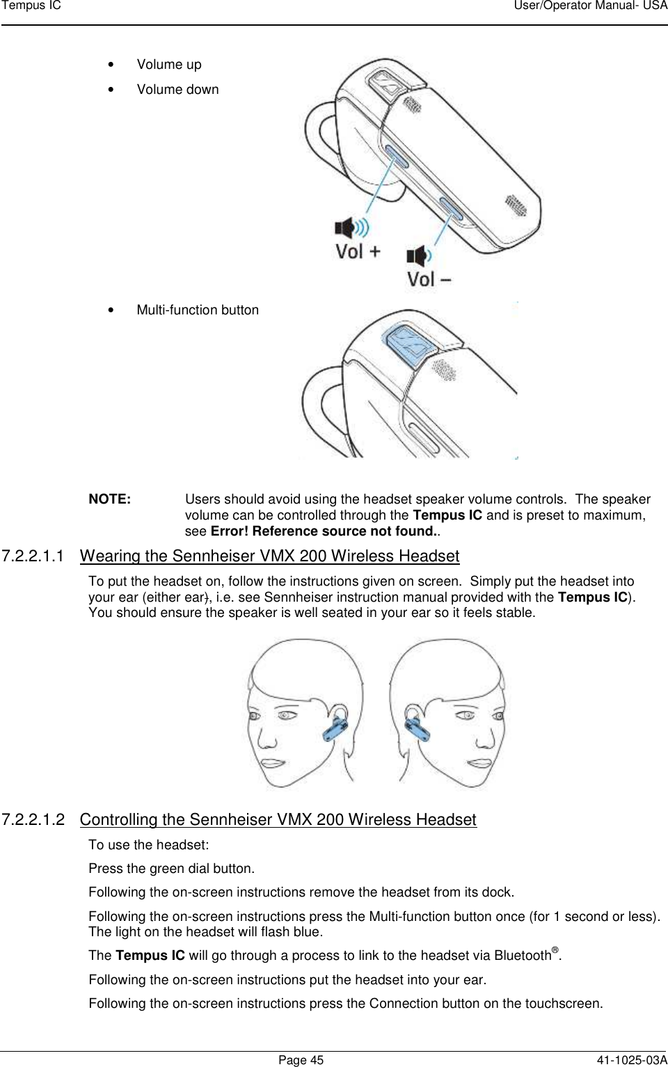
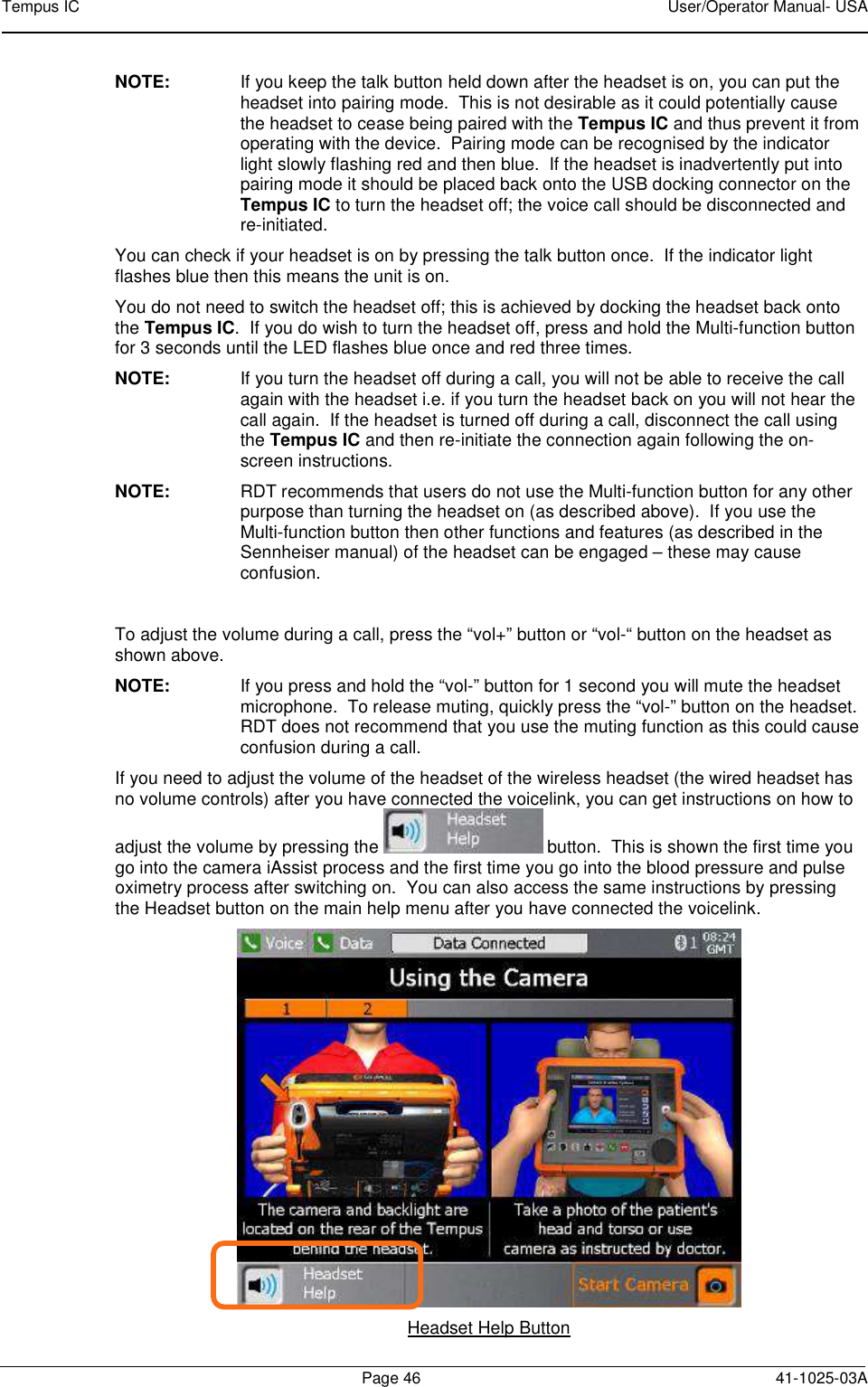
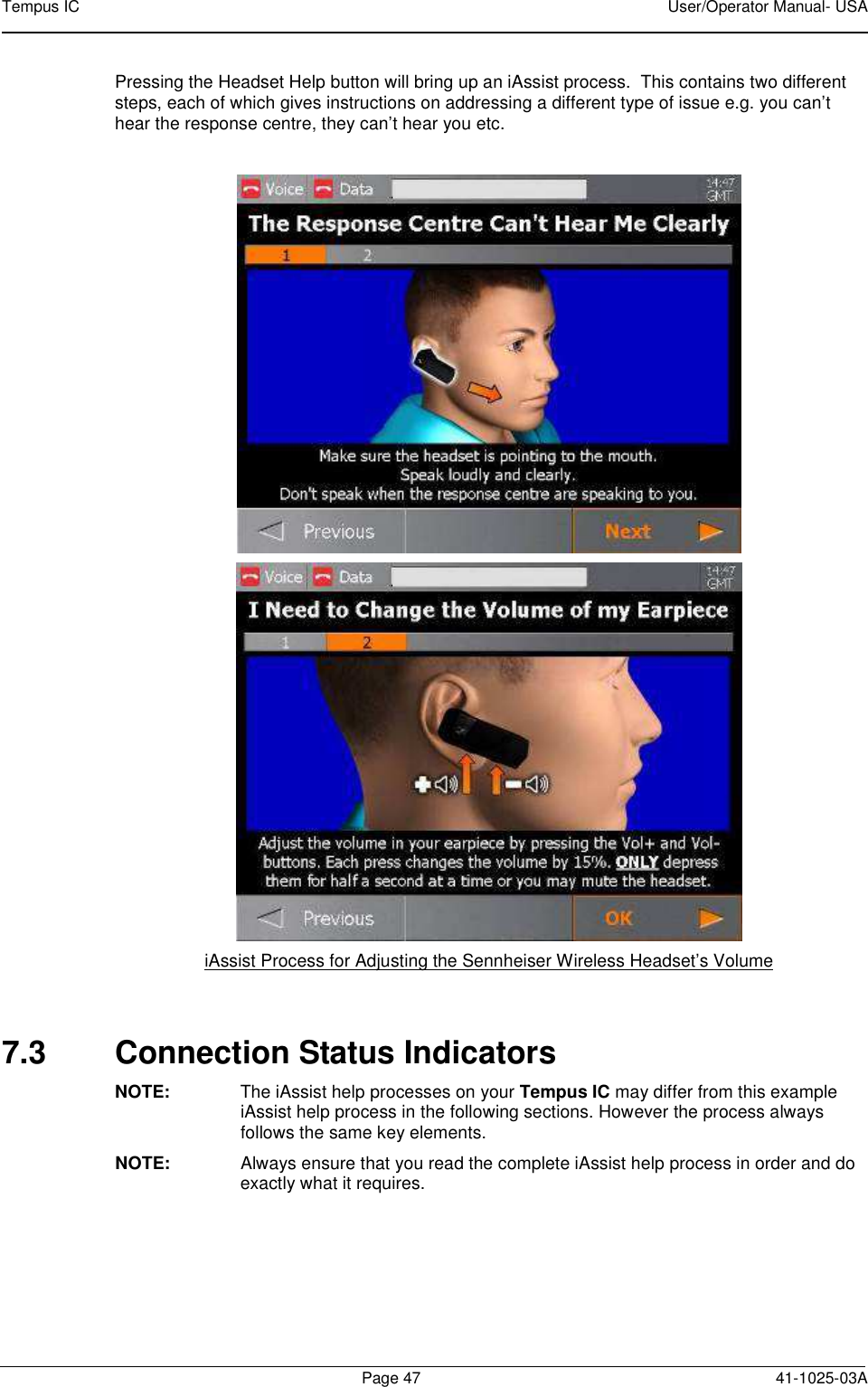
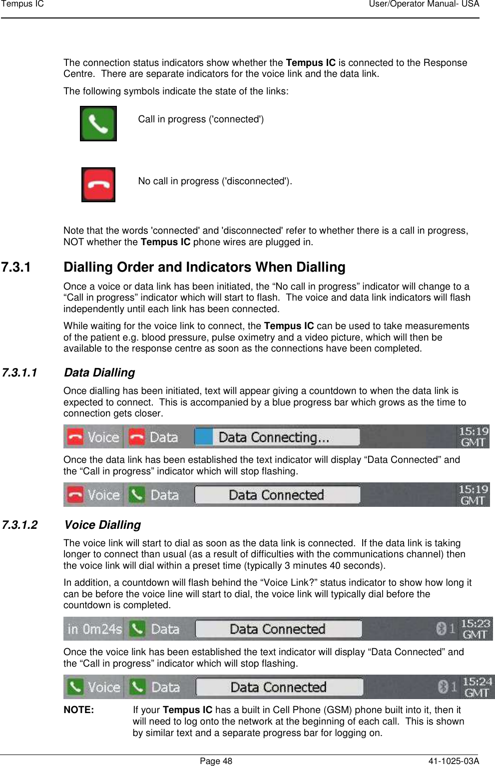
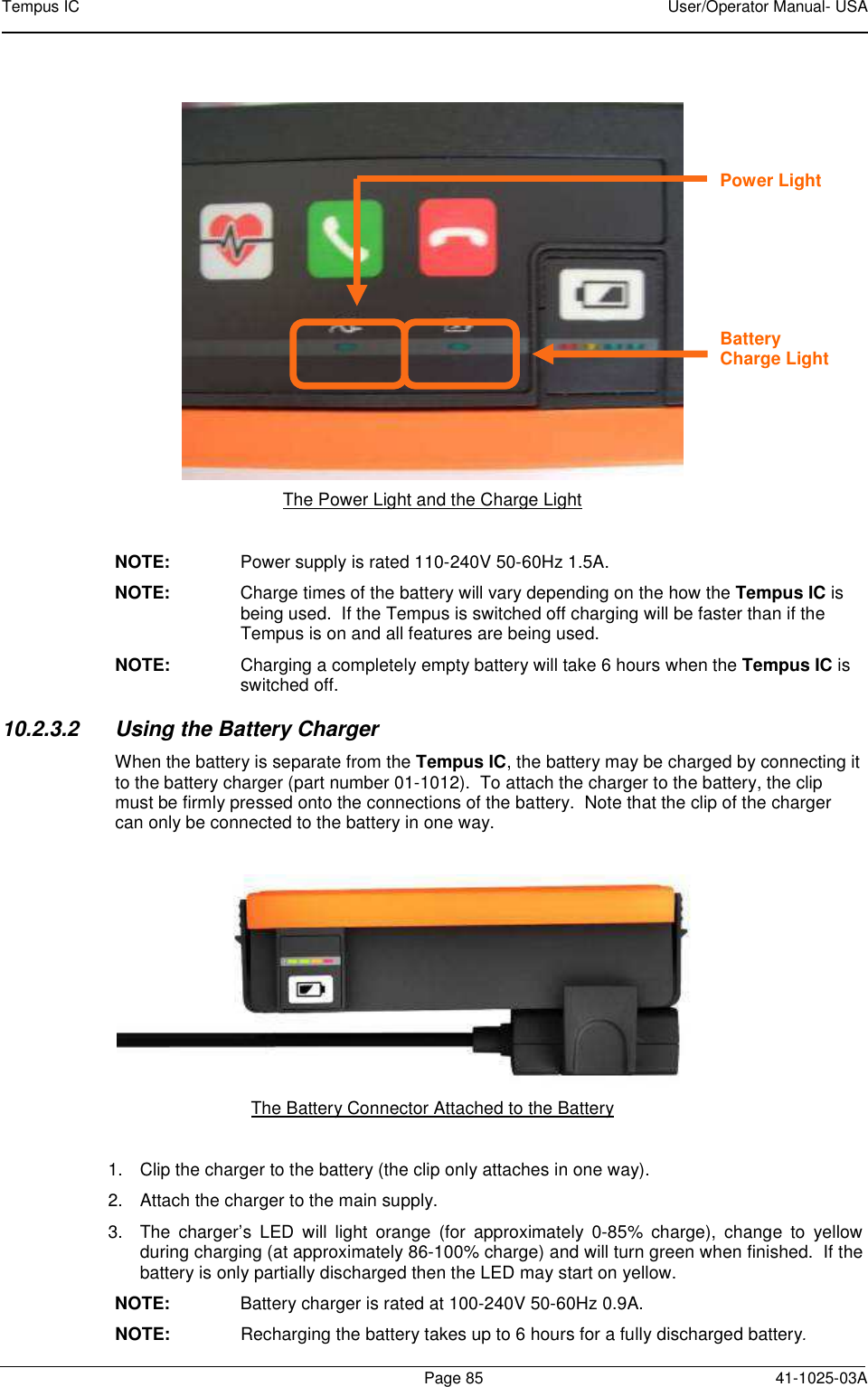
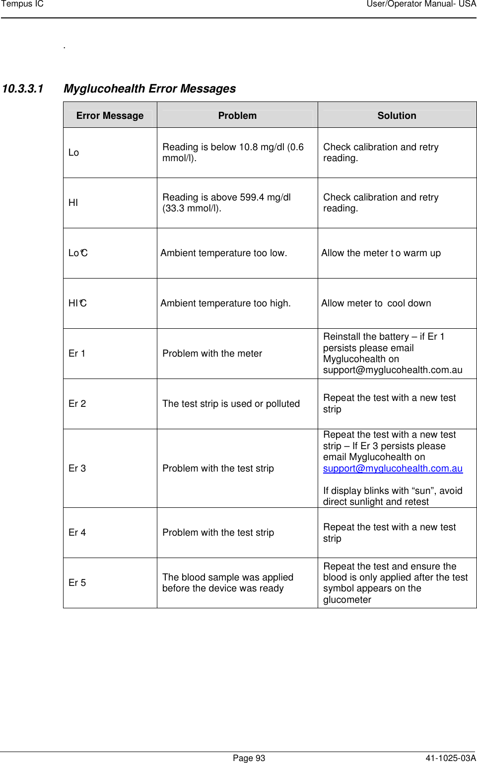
Remote Diagnostic Technologies TEMPUSIC-2 Quadband GSM/GPRS Module User Manual Tempus IC Host User Operator Manual
Remote Diagnostic Technologies Ltd. Quadband GSM/GPRS Module Tempus IC Host User Operator Manual
UserManual.wiki
>
Remote Diagnostic Technologies
>
TEMPUSIC 2 User Manual
Tempus IC Host User-Operator Manual
Navigation menu
Upload a User Manual
Namespaces
Wiki Guide
HTML
PDF
Info
Views
User Manual
Discussion / Help
Navigation
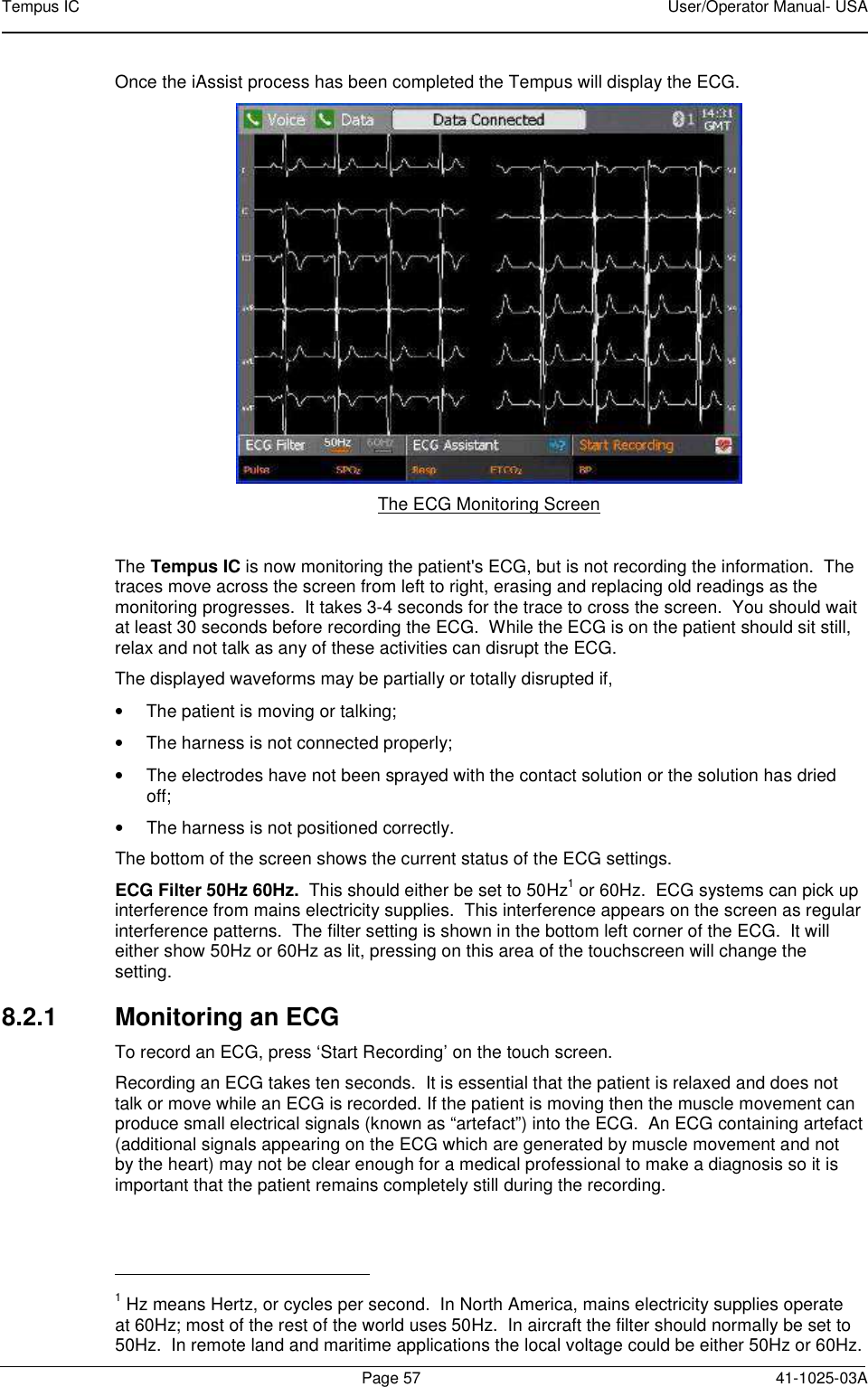
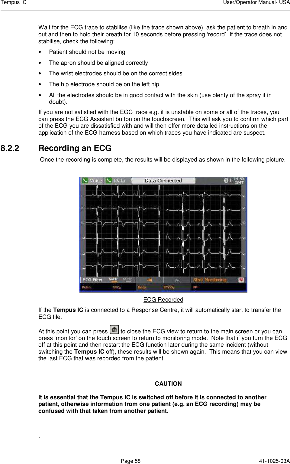
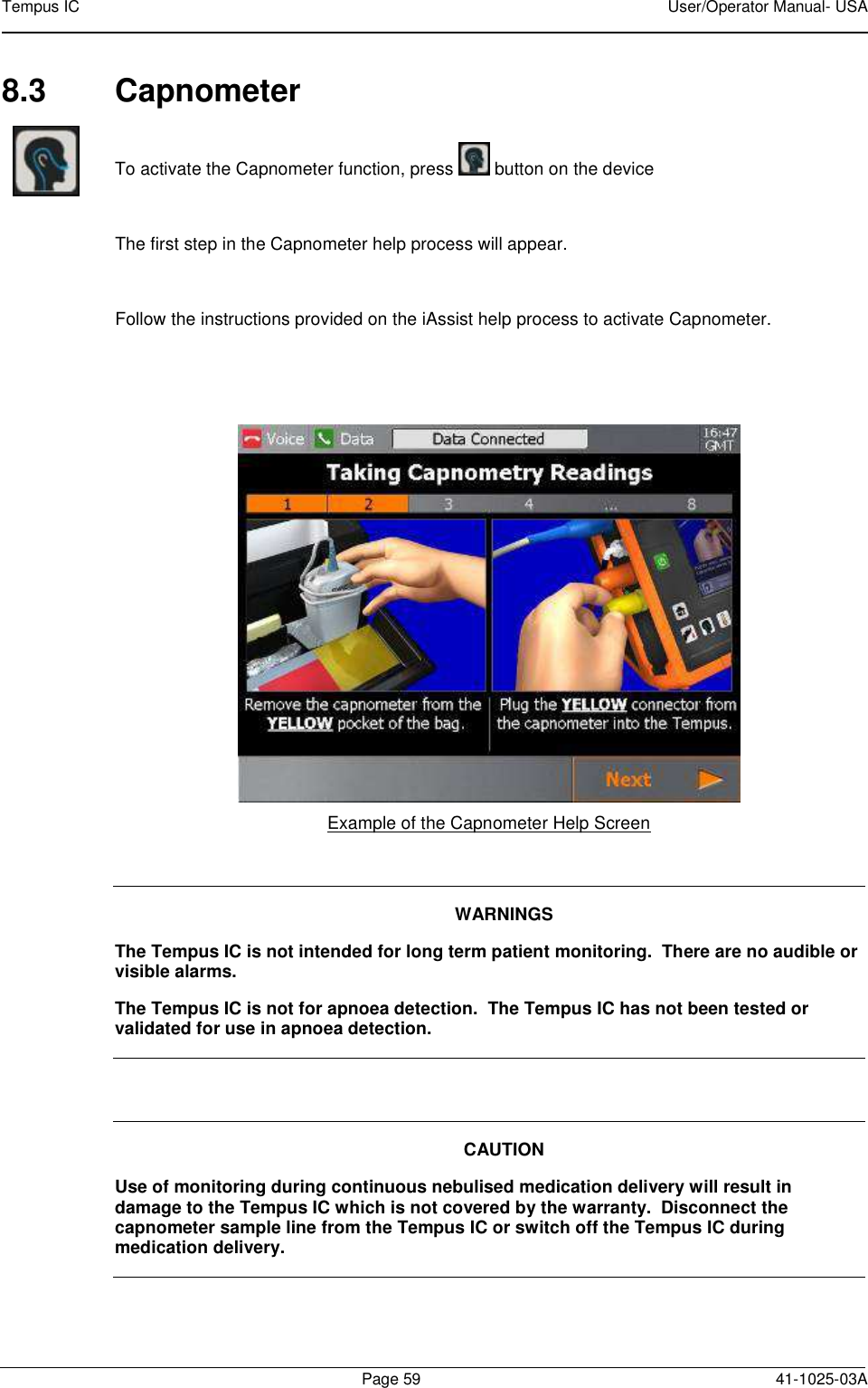
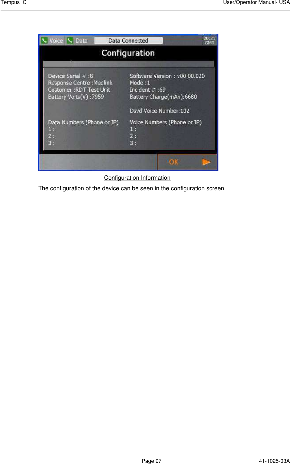
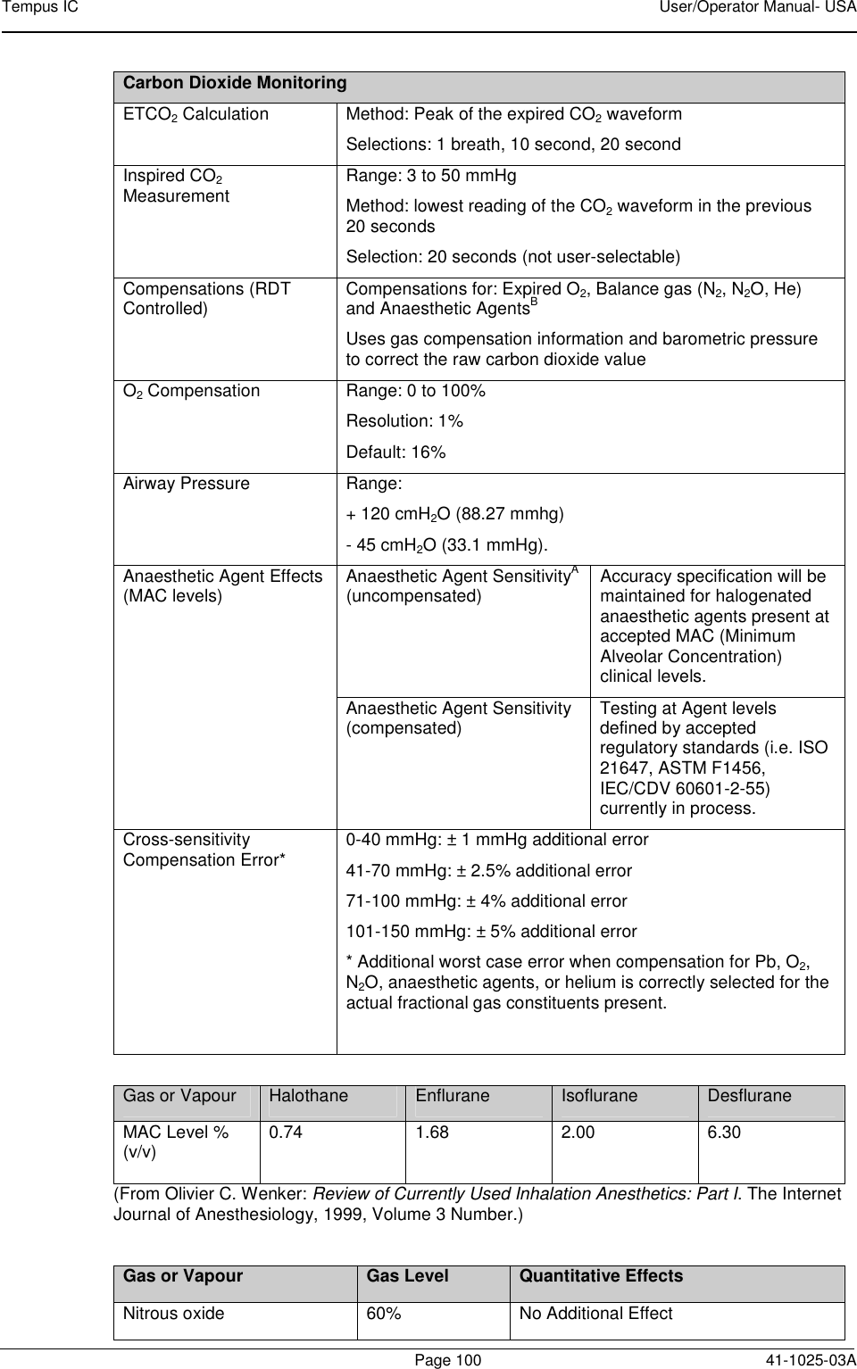
![Tempus IC User/Operator Manual- USA Page 99 41-1025-03A 13.1.3 ETC02 Sensor Unless otherwise stated, all CO2 measurements are made following an airway adapter zero, with 5% CO2 gas, balance N2 at 25 degrees C, and Pb = 760 mmHg with 2 litres per minute flow. The stabilization time for full specification testing of the LoFlo Module over the entire temperature range is 20 minutes. Range: 0-100 BPM Accuracy: ± 2 BPM Range: 0-10% CO2 displayed value Accuracy: ± 4% Rise time: <2 seconds Delay time: 5 seconds Operating altitude range: 0-15000 feet The capnometer is automatically compensated for local atmospheric pressure. Physical characteristics: Module weight is less than 9.6 oz (272.16 g) Module Size: < 2.6" wide x 1.5" high x 3.5" deep [< 66.0 x 38.1 x 88.9 mm] Cable length – 19 inches (46 cm) Carbon Dioxide Monitoring Mode of Sampling Sidestream Principle of Operation Non-dispersive infrared (NDIR) single beam optics, dual wavelength, no moving parts. Initialization Time Measurement displayed in less than 20 seconds, At an ambient temperature of 25° C, full specifications w ithin 2 minutes. CO2 Measurement Range 0 to 150 mmHg 0 to 19.7% 0 to 20 kPa (Barometric Pressure supplied by RDT) CO2 Calculation Method BTPS (Body Temperature Pressure Saturated) CO2 Response Time <3 seconds - includes transport time and rise time CO2 Resolution 0.1 mmHg 0 to 69 mmHg 0.25 mmHg 70 to 150 mmHg CO2 Accuracy * 0 - 40 mmHg ± 2 mmHg 41 - 70 mmHg ± 5% of reading 71 - 100 mmHg ± 8% of reading 101 - 150 mmHg ± 10% of reading Above 80 breath per minute ± 12% of reading * NOTE: Gas temperature at 25° C. CO2 Stability Short Term Drift: Drift over four hours shall not exceed 0.8 mmHg maximum. Long Term Drift: Accuracy specification will be maintained over a 120 hour period. CO2 Noise RMS noise of the sensor shall be less than or equal to 0.25 mmHg at 5% CO2 Sampling Rate 100 Hz Respiration Rate Range 2 to 150 breaths per minute (BPM) Respiration Rate Accuracy ± 1 breath Calibration No routine user calibration required.](https://usermanual.wiki/Remote-Diagnostic-Technologies/TEMPUSIC-2/User-Guide-1999322-Page-100.png)