Remotec Technology BW8490 AC Master (Z-Wave to IR Extender) User Manual
Remotec Technology Limited AC Master (Z-Wave to IR Extender) Users Manual
Users Manual
ZXT-600
AC MASTER
INSTALLATION GUIDE

1
Table of Contents
Introduction .......................................................................................... 2
Product Overview.................................................................................2
Key Descriptions ......................................................................................................... 2
Features ..................................................................................................................... 3
Z-Wave Glossary ........................................................................................................ 3
Get Started ............................................................................................ 5
Step 1 Apply Power to ZXT-600 .................................................................................. 5
Step 2 Include ZXT-600 to a Z-Wave Gateway ............................................................ 5
Step 3 Setup Automatic Status Report Association to Gateway .................................. 6
Step 4 Setup Air Conditioner IR code .......................................................................... 6
Other Setup Options through Configuration .................................. 13
Support for Association Groups .................................................................................. 16
Reset to Factory Default ...................................................................... 17
Mounting .............................................................................................. 17
Required tools and supplies ........................................................................................ 17
CAUTION .................................................................................................................... 17
Mounting Location Tips .............................................................................................. 18
Mounting the ZXT-600 ............................................................................................... 18
Technical Specifications ......................................................................19
WARRANTY ............................................................................................ 20
Regulatory information .......................................................................21
IC Notice .................................................................................................22
Warnings ................................................................................................22
Caution ...................................................................................................22
2
Introduction
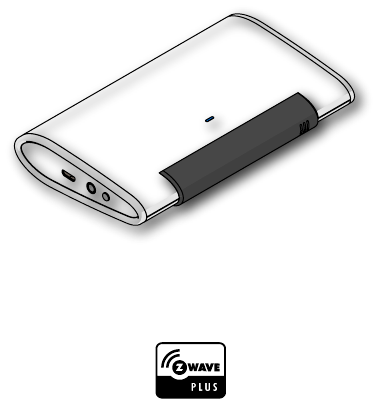
ZXT-600, AC Master, is a Z-Wave plus compliant Z-Wave-to-IR Bridge
to control split air conditioner by receiving Z-Wave command and
translating to Infrared command. With its comprehensive built-In
and cloud-stored IR database (library). ZXT-600 can control dierent
brands and models of air conditioners worldwide.
ZXT-600 is a security enabled Z-Wave plus device. A security Enabled
Z-Wave Plus Controller must be used in order to fully utilize the
product.
ZXT-600 is a Z-Wave slave device, it depends on gateway to setup
particular AC brand with correct IR code. Dierent gateway has dif-
ferent user interface for setup.
Product Overview
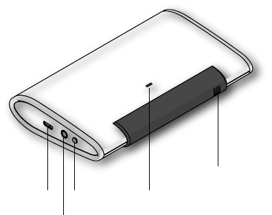
Key Descriptions
Micro USB
Phone Jack
Switch LED Indicator
Temperature Sensor

3
Features
Z-Wave Glossary
• Working as a Z-Wave thermostat
• Support classic inclusion and NWI
• Built-in air conditioner IR codes, as well as cloud-based IR code
library
• IR learning back up
• Built-in temperature sensor for room temperature report
• Working on battery (2x AA batteries) and/or USB power
Device or Node Devices and nodes are all terms to describe
an individual Z-Wave device. These are all
interchangeable when setting up your Z-Wave
network.
Inclusion Add a Z-Wave device to the network.
Exclusion Remove a Z-Wave device from the network.
Remove To take a device out of a group, scene or association
group while that device still exists in the same Z-Wave
network.
Network Wide
Inclusion (NWI)
Network Wide Inclusion (NWI) enables both end-
user friendly, Plug and Play like Z-Wave network
installation as well as professional installation
scenario where the inclusion process, in terms of
time will be reduced significantly. NWI is a feature
supported by a new frame type named Explorer
which enables the Z-Wave protocol to implement
Adaptive Source Routing.

4
Z-Wave Network A collection of Z-Wave devices is controlled by
primary and secondary controllers operating on the
same system. A Z-Wave network has its own unique
ID code so that controllers not in the network cannot
control the system.
Primary Controller The rst controller is used to set up your devices and
network. Only the Primary Controller can be used
to include or remove devices from a network. It is
recommended that you mark the primary controller
for each network for ease in modifying your network.
FLiRS Mode FLiRS is abbreviation for "Frequently Listening
Routing Slave".
FLiRS mode is targeted for battery operated
applications and will enter sleep mode frequently in
order to conserve battery consumption. The response
to Z-Wave command is not as quick as Always
Listening Device. Normally there is 1-2 seconds
latency.
Always
Listening Mode
Always Listening Mode is targeted for AC power
operated applications and it can act as a repeater,
which will re-transmit the RF signal to ensure that
the signal is received by its intended destination
by routing the signal around obstacle and radio
dead spots. The response to Z-Wave command is
immediate.
Association Association is used to organize nodes in different
groups allowing the device to identify the nodes by
a group identier. The groups can also be copied to
other devices.
5
Get Started
• Open the box
• ZXT-600 AC Master x 1pc
Step 1 Apply Power to ZXT-600
• 2x AA batteries or micro USB
• ZXT-600 will detect the rst applied power source to decide what
Z-Wave device role it will be in after included into the Z-Wave
gateway: battery= sleeping device (FLiRS mode). USB power =
always awake device (Always Listening mode), refer to Z-Wave
Glossary for more information.
• Once the ZXT-600 is included into a Z-Wave network, the working
mode (sleeping or awake) cannot be changed, unless it is exclud-
ed and re-apply the power.
• ZXT600 can be included and operated in any Z-Wave network
with other Z-Wave certified devices from other manufacturers
and/or other applications. All non-battery operated nodes within
the network will act as repeaters regardless of Vendor to increase
reliability of the network.
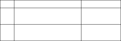
Step 2 Include ZXT-600 to a Z-Wave Gateway
Step Procedure / Description Status Indicator
1
Refer to your primary controller to enter
into the Inclusion Mode or Exclusion
Mode
2
When it is prompted to enter it, please
triple click the “PROG” button within 1
second.
Green Indicator ashes
TWICE then stay o

6
Notes:
1. It is recommended to perform the Remove (Exclude) procedure before per-
forming an Add (Include) procedure.
2. Red Indicator ashes TWICE then stay off to represent the Add / Remove pro-
cess failed, please repeat the above step again.
3. If the Add (Include) process fails, try Remove (Exclude) and /or resetting the
AC Master to Factory Default and repeat the above step.
Step 3 Setup Automatic Status Report Association to Gateway
Step 4 Setup Air Conditioner IR code
• The UI of set up the IR code varies from dierent gateways. If gate-
ways have dedicated UI for the IR code setup please refer to the
gateway UI and ignore the below steps.
• If your gateway does not have dedicated UI for ZXT-600 IR code
setup, but support Z-Wave thermostat Command Class and Con-
guration Command Class. You may refer to below steps to setup
the IR code using the conguration options in your gateway
ZXT-600 supports 1 association group
Association Group #1
Association Group #1 (max. 1 node) is default to associate with the
primary controller (Gateway/Hub/Controller) for AC Master Status
change report, refer to below for report details:
• Current Room Temperature (report in precision of 0.5°C or 1°F) (It
will be according to Conguration Parameter 39 setting to decide
the trigger level)
• Current Battery Level (Only apply in Low Battery Warning hap-
pened)
• Device Reset Locally Notication (Only report when the AC Master
has been triggered the RESET TO DEFAULT)
7
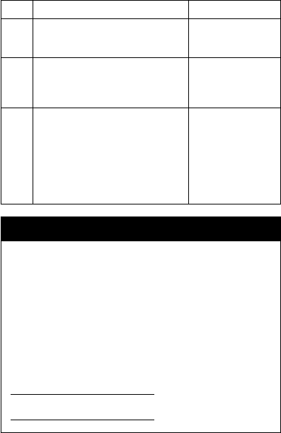
Step Procedure / Description Status Indicator
1
Refer to your primary controller user
manual, enter to the browser page that
can input the Conguration parameter.
2
Input parameter number “27” and
parameter value (Go to our Website to
search the corresponding Code Number).
Then complete the Conguration process.
Green Indicator will
turn on. If fail, Red Indi-
cator will ash TWICE.
3
Go back to the control page of AC Master
on the gateway’s Browser and try the
function such as (Cool, Temperature Set).
If the Air Conditioner does not respond
to the command you set on the Gateway
(Cool, Heat, Auto, Temperature Set,
etc….), repeat Step 2 and 3 to Select the
next IR Code on the search list.
Green Indicator ashes
ONCE every time if
receives a command
from Gateway
Important Information
• Dierent brand or model of air conditioner has dierent function.
For example, some air conditioner only support temperature set
from 18°C - 30°C, if user set 17°C on gateway, AC Master will not
respond.
• There are more than 1 code for each brand, some does not
support Heat, if User selected a code that does not support
Heat but Original air conditioner supports Heat Function, please
continue to try next code until the correct one is selected.
• You can record down your Device Code for future reference after
setting up the AC Master correctly.
AC Device programmed to your AC Master
Code Number :
8
IR Code Learning
Step Procedure / Description Status Indicator
1
Refer to your primary controller user
manual, enter to the browser page that
can input the Conguration parameter
2
Look up Below mapping table for
learning, and decide the IR setting you
intent to learn next.
3
Open the Gateway’s Configuration
Brower page input parameter number
“25” and parameter value (according to
below Mapping Table), then complete the
Conguration process.
Then Green Indicator
still turns ON for
indicating the IR Code
Learning Start
4
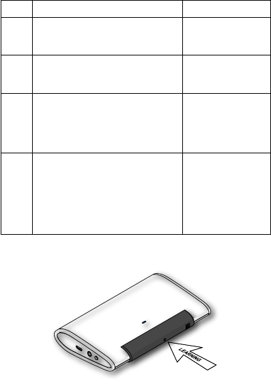
Aim the Original Air Conditioner Remote
at AC Master according to below position
within 1-3cm
Press "Power ON" button on the Original
Air Conditioner Remote. If the Learning
is failed, repeat Step 3 to step 5, To learn
next IR code, repeat Step 2 to step 5.
Successful:
Green Indicator ashes
TWICE
Unsuccessful:
Red Indicator flashes
TWICE

9
Tips
• Make sure your Original Remote is in Power OFF Status.
• Make sure your Original Remote set FAN Speed to AUTO and FAN
SWING to AUTO/ON
• Press and Hold the Power Key on Original Remote before AC
Master indicate Successful or Not.
• Keep away from Incandescent Light or Direct Sunlight during
learning.
• Make sure IR Transmitter of your Original Remote alight with
learning diode of AC Master, you may also slight adjust closer or
further away the distance of two devices. Some of Remotes the
IR transmitter in hidden behind lens and may not installed center
of remote.
• Make sure the power is good on both devices, especially
the Original remote. Use Fresh Batteries in both devices
recommended.
10
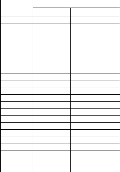
IR Learning Mapping Table (Parameter Number 25)
Parameter Value
(Storage Location)
Thermostat Command & IR Setting
Storage in Celsius Unit Storage in Fahrenheit Unit
6 OFF
2 ON (RESUME)
201 17°C COOL 63°F COOL
202 18°C COOL 64°F COOL
203 19°C COOL 66°F or 67°F COOL
204 20°C COOL 68°F or 69°F COOL
205 21°C COOL 70°F or 71°F COOL
206 22°C COOL 72°F or 73°F COOL
207 23°C COOL 74°F or 75°F COOL
208 24°C COOL 76°F COOL
2 25°C COOL 77°F or 78°F COOL
209 26°C COOL 79°F or 80°F COOL
210 27°C COOL 81°F or 82°F COOL
211 28°C COOL 83°F or 84°F COOL
212 29°C COOL 85°F COOL
213 30°C COOL 86°F COOL
216 17°C HEAT 63°F HEAT
217 18°C HEAT 64°F HEAT
218 19°C HEAT 66°F or 67°F HEAT
219 20°C HEAT 68°F or 69°F HEAT
220 21°C HEAT 70°F or 71°F HEAT
221 22°C HEAT 72°F or 73°F HEAT

11
222 23°C HEAT 74°F or 75°F HEAT
223 24°C HEAT 76°F HEAT
5 25°C HEAT 77°F or 78°F HEAT
224 26°C HEAT 79°F or 80°F HEAT
225 27°C HEAT 81°F or 82°F HEAT
226 28°C HEAT 83°F or 84°F HEAT
227 29°C HEAT 85°F HEAT
228 30°C HEAT 86°F HEAT
3 DRY MODE DRY MODE
1 AUTO MODE AUTO MODE
4 FAN MODE FAN MODE

12
Important Information
After all learning completed, User can go back to the ZXT-600
control page on the gateway for normal operation.
• On the Gateway UI, User can only use the Temperature range
from the mapping table, OFF, ON(RESUME), COOL, HEAT, DRY
MODE, AUTO MODE and FAN MODE.
• If User only learnt ON(RESUME), OFF, or part of the settings
according to the above table, ZXT-600 will send the learnt
data to the Air Conditioner only. For example, User only learnt
ON(RESUME), OFF, 22°C COOL, 24°C HEAT, ZXT-600 will not
send the IR Data to Air Conditioner if User set 27°C Cool on the
gateway.
• User can still use gateway to set up Scene and Schedule with
ZXT-600. For example, to have AC turn on at 23°C every day at
7am, 25°C at 11pm. Just make sure the set code is learnt.
• The learning mapping table is for split Air Conditioner, which
Remote Control is with LCD Display. For Window type Air
Conditioner (which Remote Control is without LCD Display), the
mapping table with temperatures do not apply, due to dierent
type of IR Control Protocol. However, User may still use OFF,
ON(RESUME), DRY, AUTO or FAN Key for Learning.
• (Because the POWER key on the Original Remote (without LCD
Display) is toggle, user can choose either ON key or OFF key to
learn Power key. After Learning is done, press once to turn on the
Air Conditioner if the Air Conditioner is OFF, press once to turn
OFF if the Air Conditioner is ON)

13
Other Setup Options through Conguration
Functions Parameter
Number Parameter Value Size
( bytes)
Learn IR code 25 (0x19)
Default: 0x0000
range: (0x0000 to 0x01B6)
refer to learning mapping table
2
Check IR Code
Learning
Status
(Read Only)
26(0x1A)
Default: 0x00
range: 0 to 4 (0x00 to 0x04)
0x00 : Idle - IR Channel is idle
0x01 : OK - the last learning
operation was
completed successfully
0x02 : Learning - ZXT-600 is busy
processing previous learning request
0x03 : Full – All locations are being
used.
0x04 : The last learning request was
failed
Note:The status value 0x01 and
0x04 will be reset to 0x00 after ZXT-
600 receives a get command to this
parameter.
1
Set IR Code
number from
built-in
code library
27 (0x1B) Refer to “Code List” 2

14
Set Built-
in IR Emitter
Control
( If there
have two
or more Air
Conditioners
with the same
code set that
are used in
the same
room, user
can disable
the built-
in IR emitter
and use the
external IR
emitter cable
to control
each air
conditioner
32 (0x20)
Default: 0xFF
0 or 255
(0x00 or 0xFF)
0x00: Disable
0xFF: Enable (Default)
1
Control Air
Conditioner
“SWING”
function
33 (0x21)
Default: 0x01
Range 0 to 1 (0x00 or 0x01)
0x00 : Swing OFF
0x01 : Swing Auto (Default)
1

15
Calibrate
temperature
reading
37 (0x25)
Temperature oset value.
0x00 = 0°C (Default)
0x01 = 1°C
0x02 = 2°C
0x03 = 3°C
0x04 = 4°C
0x05 = 5°C
0xFF = -1°C
0xFE = -2°C
0xFD = -3°C
0xFC = -4°C
0xFB = -5°C
1
Set Auto
Report
Condition
Trigger
By Room
Temperature
change
30 (0x1E)
0x00 = Disable AUTO report function
(Default)
(for saving battery life)
Auto report if room temperature is
dierent from last report.
0x01 = 1°F (0.5°C)
0x02 = 2°F (1°C)
0x03 = 3°F (1.5°C)
0x04 = 4°F (2°C)
0x05 = 5°F (2.5°C)
0x06 = 6°F (3°C)
0x07 = 7°F (3.5°C)
0x08 = 8°F (4°C)
1
Set Auto
Report
Condition
By
Time Interval
34 (0x22)
0x00 = Disable AUTO report function
(Default)
Auto report by the following time
interval.
0x01 = 1 Hr
0x02 = 2 Hrs
0x03 = 3 Hrs
0x04 = 4 Hrs
0x05 = 5 Hrs
0x06 = 6 Hrs
0x07 = 7 Hrs
0x08 = 8 Hrs
1

16
Note:
All the above Parameter Number and Value is in Hexadecimal Numbering Format,
if the Gateway only support decimal numbering format, please change it to deci-
mal value accordingly.
Mapping Information
• BASIC Set Value 0x00 will map to Thermostat mode OFF 0x00
• BASIC Set Value 0xFF will map to Thermostat mode Resume 0x05
• Energy Saving Mode will map to Thermostat mode OFF
• Comfort Mode will map to Thermostat mode Resume 0x05
Support for Association Groups
ZXT-600 supports 1 association group
Association Group #1
Association Group #1 (max. 1 node) is default to associate with the
primary controller (Gateway/Hub/Controller) for AC Master Status
change report, refer to below for report details:
• Current Room Temperature (report in precision of 0.5°C or 1°F)(It
will be according to Conguration Parameter 39 setting to decide
the trigger level)
• Current Battery Level (Only apply in Low Battery Warning hap-
pened)
• Device Reset Locally Notication (Only report when the AC Master
has been triggered the RESET TO DEFAULT)
17
Reset to Factory Default
Press and Hold “PROG” button for 3 seconds on AC Master, the Green
Indicator will light up. DO NOT Release the “PROG” Button until
Green Indicator ashes TWICE.
Mounting
Required tools and supplies
• Phillips Screwdriver
• Drill
• Drill bit (3/16” for drywall, 7/32” for plaster)
• Hammer
• Pencil
• Level (optional)
• AA Alkaline Battery 2pcs (Not Included) or 5VDC 1A Power Adap-
tor with 1.5m long Micro USB Cable (Not Included)
CAUTION
• Use new batteries of the recommended type and size only
• Never mix used and new batteries together
• To avoid chemical leaks, remove batteries from the ZXT-600 if you
do not intend to use the device for an extended period of time.
• Dispose of used batteries properly; do not burn or bury them.
18
Mounting Location Tips
The ZXT-600 should be mounted on an inner wall about 5ft (1.5m)
above the oor where it is readily aected by changes of the general
room temperature with freely circulating air.
Before mounting, check the material and structure of the mounting
location. If the location does not have the proper material or struc-
ture, the ZXT-600 can fall and cause an inquiry.
Avoid mounting above or near hot surfaces or equipment (e.g. TV,
Heater, Refrigerator). Avoid mounting where it will be exposed to
direct sunshine, drafts, or in a laundry room or other enclosed space.
Better to mount your device where it has no any obstacle or blocked
object between the device and your AC Appliance.
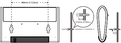
Mounting the ZXT-600
• Position ZXT-600 on wall, level and mark hole positions with pen-
cil.
• Drill holes at marked positions, then tap in supplied wall anchors.
• Insert and tighten mounting screws as below gure

19
Technical Specications
Model no. BW8490US (ZXT-600US)
BW8490EU (ZXT-600EU)
BW8490AU (ZXT-600AU)
BW8490JP (ZXT-600JP)
BW8490KR (ZXT-600KR)
BW8490IN (ZXT-600IN)
BW8490CN (ZXT-600CN)
RF Frequency 908.4MHz (ZXT-600US)
868.4MHz (ZXT-600EU)
921.4MHz (ZXT-600AU)
922.5MHz (ZXT-600JP)
920.9MHz (ZXT-600KR)
865.2MHz (ZXT-600IN)
868.4MHz (ZXT-600CN)
RF
Operating Distance
Up to 132ft outdoor line of sight, in unobstructed
environment
Temperature
Measurement
Measurable range : 0°C ~ 40°C / 32°F ~ 104°F
Report resolution : 0.5 Degree C / 0.5 Degree F
Operating
Ambient
Temperature
0°C ~ 40°C, non-condensing
Storage
Temperature
-10°C ~ 50°C
Powered By USB Power DC 5V 1A or Alkaline Primary Batteries
AA x 2pcs
Dimension (L x H x T) 128mm x 78mm x 22mm
Weight 84g (Batteries excluded)

20
WARRANTY
ONE-YEAR LIMITED WARRANTY: Remotec warrants this product to
be free from defects in materials and workmanship under normal
use and service for a period of one year from the original date of
purchase from the distributors or dealer.
REMOTEC shall not be liable for:
• Damages caused by defective devices for indirect, incidental, spe-
cial, consequential or punitive damages, including, inter alia, loss
of prots, savings, data, loss of benets, claims by third parties and
any property damage or personal injuries arising from or related
to the use of the device.
• Service trips to provide instruction on product use.
• Shipping costs for replacement products.
This warranty is limited to the repair or replacement of this product
only, if the purchase date cannot be substantiated, the warranty
period will begin on the date of manufacture as indicated on this
product. All warranty claims must be made to Remotec appointed
distributors or dealers during the applicable warranty period. This
warranty gives you specic legal right and you may also have other
rights which vary in each country.
Website : http://www.remotec.com.hk

21
Regulatory information
FCC Compliance Statement
This device complies with Part 15 of the FCC rules. Operation is sub-
ject to the following two conditions:
• This device may not cause harmful interference, and
• This device must accept any interference received, including inter-
ference that may cause undesired operation.
This equipment has been tested and found to comply with the lim-
its for a Class B digital device, pursuant to Part 15 of the FCC Rules.
These limits are designed to provide reasonable protection against
harmful interference in a residential installation. This equipment
generates, uses and can radiate radio frequency energy and, if not
installed and used in accordance with the instructions, may cause
harmful interference to radio communications. However, there is no
guarantee that interference will not occur in a particular installation.
If this equipment does cause harmful interference to radio or televi-
sion reception, which can be determined by turning the equipment
o and on, the user is encouraged to try to correct the interference
by one or more of the following measures:
• Reorient or relocate the receiving antenna.
• Increase the separation between the equipment and receiver.
• Connect the equipment into an outlet on a circuit dierent from
that to which the receiver is connected.
• Consult the dealer or an experienced radio/TV technician for help.
Notice : Changes or modications to this unit not expressly approved by the party
responsible for compliance could void the user authority to operate the equip-
ment.
22
IC Notice
This device complies with Industry Canada licence-exempt RSS stan-
dard(s). Operation is subject to the following two conditions:
• This device may not cause interference, and
• This device must accept any interference, including interference
that may cause undesired operation of the device.
Le présent appareil est conforme aux CNR d'Industrie Canada ap-
plicables aux appareils radio exempts de licence. L'exploitation est
autorisée aux deux conditionssuivantes:
• l'appareil ne doit pas produire de brouillage, et
• l'utilisateur de l'appareil doit accepter tout brouillage radioélec-
trique subi, même si le brouillage est susceptible d'en comprom-
ettre le fonctionnement.
Warnings
• Do not modify the unit in any way.
• Risk of re.
• Risk of electrical shock.
• Risk of burns.
• Do not dispose of electrical appliances as unsorted
municipal waste, use separate collection facilities.
Contact your local government for information
regarding the collection systems available.
• There is no user serviceable parts in this unit.
Caution
• Risk of explosion if battery is replaced by an incorrect type.
• Dispose of used batteries according to the instructions.
FCC ID : M7N-BW8490