Remotec Technology BW8510 Scene Master User Manual
Remotec Technology Limited Scene Master
User manual
1
ZRC-90 (Scene Master)
Operating Instructions
Master your home, Master your life
2
Introduction
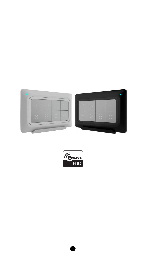
The ZRC-90 Scene Master (Figure 1) is a Z-Wave Central Scene
Controller. When one of the buttons on the ZRC-90 is pushed, your Z-
Wave central controller will receive a signal which it can use to trigger
unlimited control possibilities. With 8 buttons, each supporting a long-
press capability, you can control 16 different actions in your central
controller. The ZRC-90 is a great solution for triggering events more
quickly than taking out your smart-phone and running a home control
App. The Scene Master is ideal for kids, elderlies and guests who may
not have full access to your smart home’s mobile application and
hence may not have the rights to switch on various lighting, heating,
air conditioning and other home appliance. With a convenient snap-in
wall mount, the ZRC-90 can also be removed to keep it handy while
you go about your home for the ultimate in simple convenience.
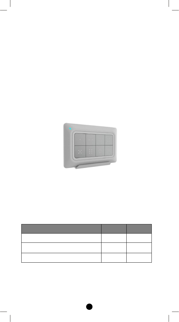
Figure 1 ZRC-90
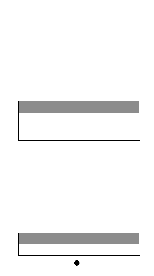
Gateway Requirements
Please make sure your gateway supports below functions before use
ZRC-90.
Z-Wave Command Class Controlled
Supported
Association command class Y N
Association Group Information (AGI)
command class Y N
Central Scene command class Y Y
3
Key Features
- Controls up to 8x2 pre-set scenes and 8 groups dimming function
- One learn-key setup and simple operation
- Report for key pressed 1 time, 2 times, released and held down
- Unlimited controlling capability through gateway
- Able to act as a primary or secondary controller
- Z-Wave Plus compliant
- Super thin, elegant design and able to mount to the wall-bracket
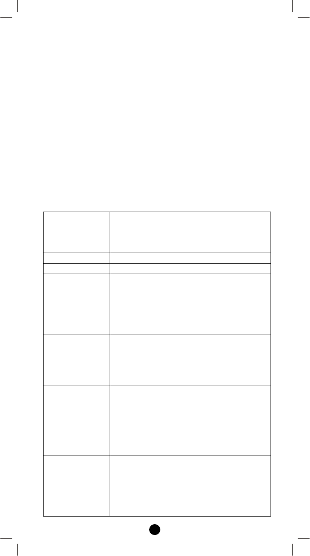
Glossary
Device or Node
Devices and nodes are all terms to describe
an individual Z‐Wave device. These are all
interchangeable when setting up your Z-
Wave network.
Inclusion Add a Z-Wave device to the network.
Exclusion Remove a Z-Wave device from the network.
Z-Wave
Network
A collection of Z-Wave devices controlled by
primary and secondary controllers operating
on the same system. A Z-Wave network has
its own unique ID code so that controllers
not in the network cannot control the
system.
Scene
A collection of Z-Wave devices configured to
turn to a specific level, setting, mode, or
perform an operation. Scenes are usually
activated by a controller, timed event, or
specific conditions.
Primary
Controller
The first controller used to set up your
devices and network. Only the Primary
Controller can be used to include or remove
modules from a network. It is recommended
that you mark the primary controller for
each network for ease in modifying your
network.
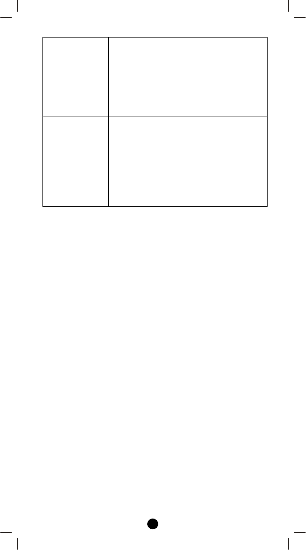
Secondary
Controller
A controller containing network information
about other modules within the network
and is used for controlling devices.
Secondary controller is created from the
Primary Controller and cannot include or
remove modules to the network.
4
SUC ID Server
(SIS)
When a SUC is also configured as a node ID
server (SIS) it enables all other controllers to
include/exclude nodes. The SIS
automatically becomes the Primary
Controller in the network when enabled.
There can only be one SIS in each individual
network. To avoid inconsistency, all node ID
allocations are maintained by the SIS.
Inclusion
Controller
The SIS enables other controllers to
include/exclude nodes to/from the network.
When SIS functionality is enabled the
controller also takes the role as the Primary
Controller because it has both latest
network topology and allocated node IDs. All
the other controllers are called Inclusion
Controllers because they can
include/exclude nodes to/from the network.
5
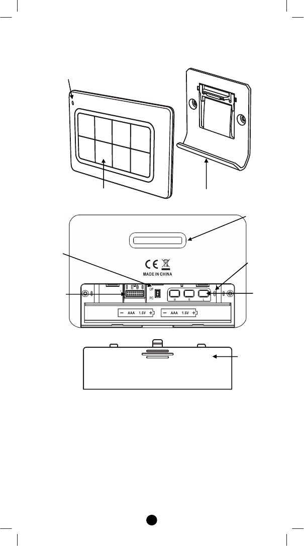
Product Overview
Figure 2 Setup and control keys of ZRC-90
LED indication for
Operation and Setup
Wall mount bracket
Scene control keyboard
Setup buttons
Upgrade
header
Upgrade slide
switch
Battery door
Back block for
plastic insert
LED indication
for Operation
and Setup
6
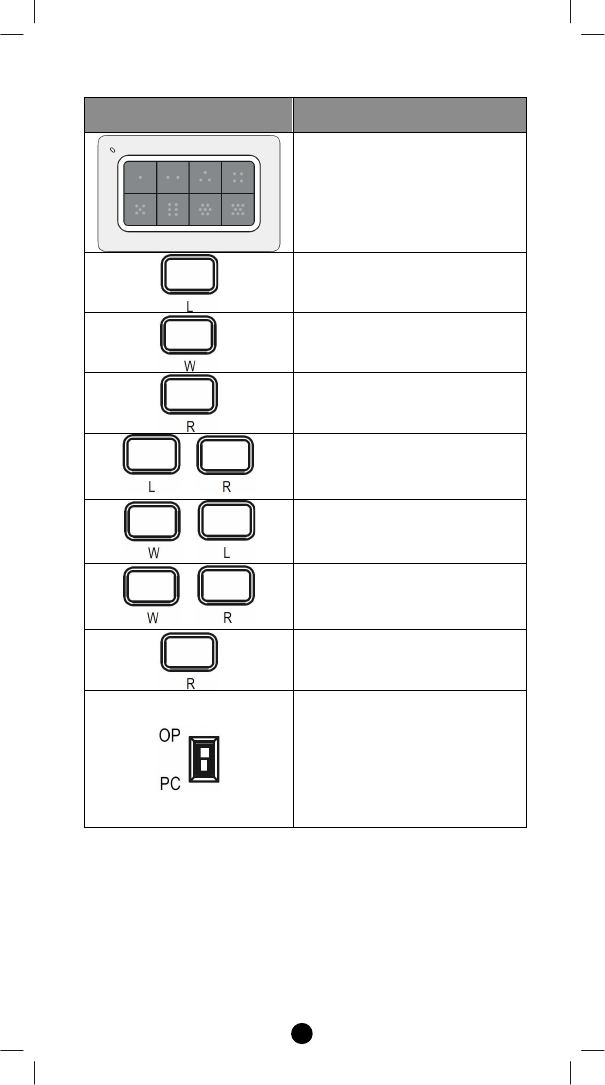
Description of Function Keys
Keys Functions
Scene control buttons
Learn mode (Click once)
Wake up (Click once)
Remove device (Click once)
+
Add device (Press the keys until
LED light up)
+
Create Primary (Press the keys
until LED light up)
+
Create Secondary (Press the
keys until LED light up)
Reset to factory default
(Press and keep holding 10
seconds then triple click)
Slide switch
OP = Normal operation (default)
PC = PC firmware upgrade mode
(The slide switch is designed for
firmware upgrade by supplier,
please switch to "OP" direction
for normal operation.)
7
Setup and Operations
Before using the ZRC-90, please install the batteries:
2xAAA (alkaline is recommended) batteries are required for
operation.
Remove the battery cover on the back of your remote.
Check the polarity of the batteries and the "+/-" marks inside the
battery compartment.
Insert the batteries.
Push the battery cover back in place.
CAUTION (battery safety)
Use new batteries of the recommended type and size only.
Never mix used and new batteries together.
To avoid chemical leaks, remove batteries from the remote
controller if you do not intend to use the remote for an
extended period of time.
Dispose of used batteries properly; do not burn or bury them.
(Please carefully read through the following sections of this user
manual and store for future reference.)
ZRC-90 can be included and operated in any Z-Wave network with
other Z-Wave certified devices from other manufacturers and/or
other applications. All non-battery operated devices within the
network will act as repeaters regardless of vendor to increase
reliability of the network.
ZRC-90 can act as a secondary Central Scene Controller and trigger
the pre-defined scenes through the gateway. Please follow “Add ZRC-
90 into gateway network” by the procedures of “Learn mode” and
“Scene activation and deactivation”.
Z-Wave Learn mode
ZRC-90 can also receive network information from other controllers
by enter “Learn mode”.
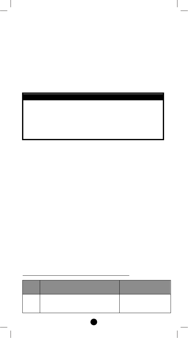
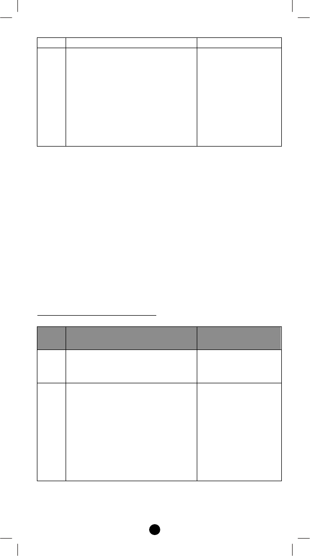
(Add / Remove ZRC-90 into / from gateway network)
Step
Setup Key Setup LED Indication
on ZRC-90
1
Refer to your primary controller
instructions to process the Inclusion
/ Exclusion setup procedure.
-
8
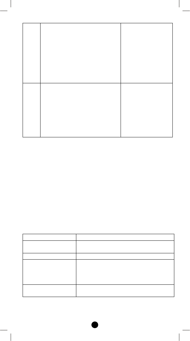
2
When prompted by your primary
controller (gateway), click once on
the “L” button.
(The primary controller should
indicate the action was successful.
If the controller indicates the action
was unsuccessful, please repeat
above procedure.)
LED will flash slowly
until complete the
step of inclusion /
exclusion.
3
User can perform scene control by
the keypad of ZRC-90.
LED flash once then
stay off if the scene
operation is valid
or
LED flashes 6 times
rapidly then stay off if
the command or
operation is invalid
Notes:
1. If the device already existed into the network, the unit will exit
Learn mode automatically after 5 seconds.
2. If the device does not exist into the network and no command
from gateway, the unit will exit Learn mode automatically after
30 seconds.
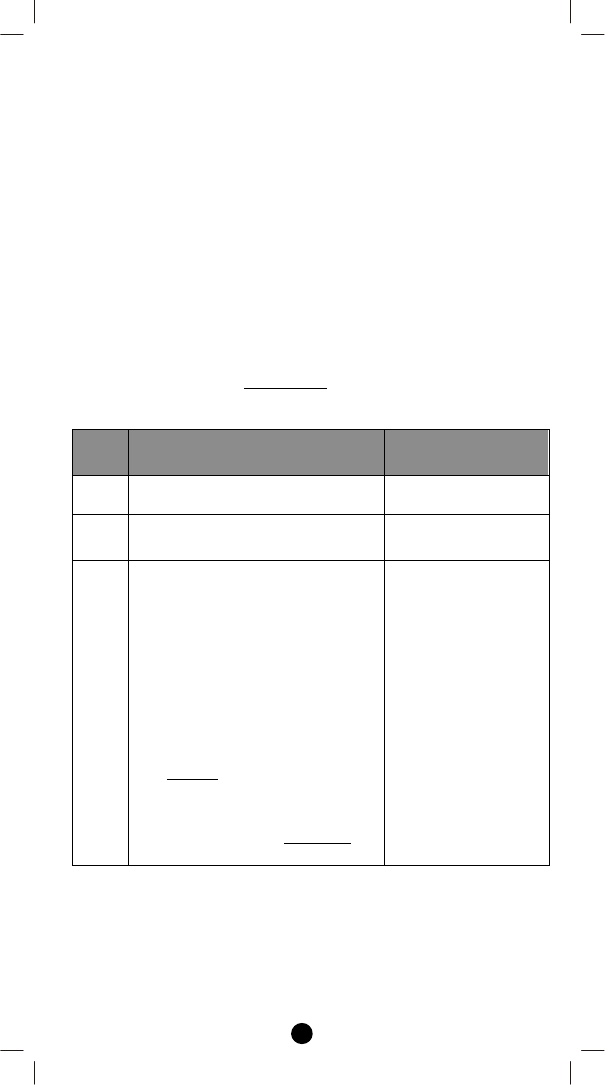
Scene activation and deactivation
The real actions of scene will be depended on each gateway
interpretation.
ZRC-90 key action Gateway interpretation example
Key pressed 1 time
(within 1 seconds )
Scene activation
Key released -
Key held down
(press and keep
holding more than 2
seconds)
Dimming up/down for a group device
Key pressed 2 times
(within 1 seconds)
Scene deactivation
9
Notes:
1. Association Group-1 will be a default status report channel in Z-
Wave+ lifeline requirement. Only one node can be assigned to
this association group.
Z-Wave Wakeup (Listening mode)
There are multiple usages by entering this mode:
Version information: To get application software version, the Z-
Wave protocol version and the supported Z-Wave command
version of this controller.
Manufacturer Specific information: To get the manufacture ID,
product type ID and the product ID of this controller.
Association configuration: To create and maintain associations to
ZRC-90.
Step
Setup Key Setup LED Indication
on ZRC-90
1
Enter to the Listening mode by click
once on “W” button.
LED will keep flashes
slowly
2
Listening mode will exit
automatically after 30 seconds of
inactivity.
LED stay off
Notes:
1. The mode must not be exited during communication process
with another controller. Please wait for entire communication
process to be completed.
2. It is not allowed to enter any user input from the remote's hard
key after entry this mode.
ZRC-90 act as a primary controller. It can perform Add/Remove
device to/from a network and create a primary/secondary controller.
Please reset ZRC-90 to factory default to act as a primary controller if
need perform Add or Remove function.
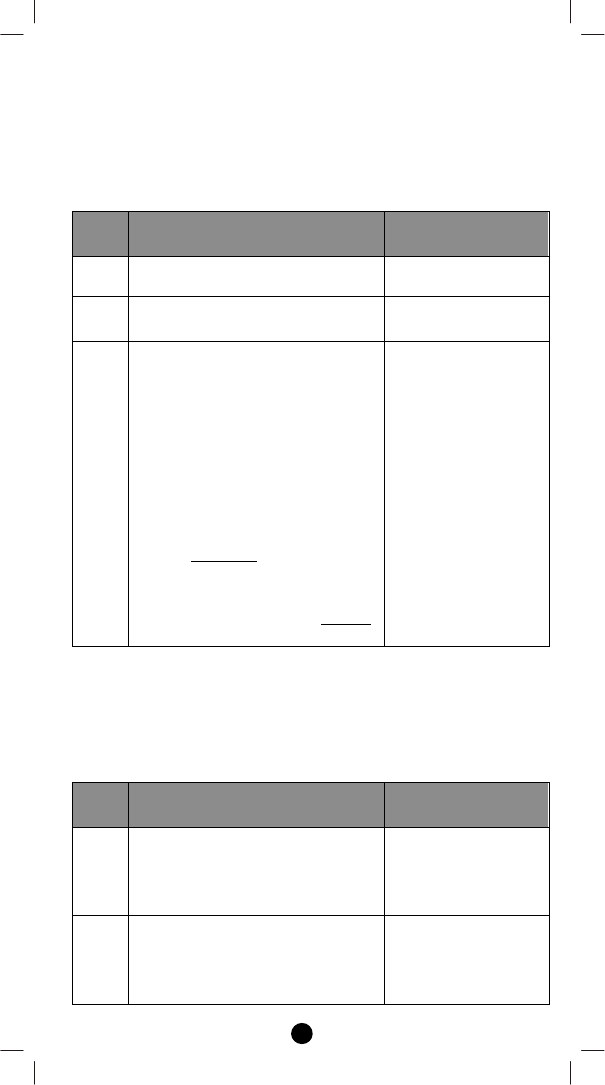
Add/Remove Devices
Adding Device to the Network
Step
Setup Key Setup LED Indication
on ZRC-90
1
Press “L+R” buttons simultaneously
until LED light up to add the device
LED will keep flashes
slowly
10
into ZRC-90 Z-Wave network.
2
Press the program button on the
target device.
LED flash once then
stay off if the device
is included into the
network
or
LED flashes 6 times
rapidly then stay off if
the operation is
invalid
Notes:
1. If you can’t add your Z-Wave device, this device might have been
included in another Z-Wave network. In this case, please remove
this device following the steps in the [Removing Device from the
Network] section then add this device again.
2. This step can be skipped if the device is already included in the
network.
3. In a Z-Wave network, only the primary controller or inclusion
controller can add or include devices into its network. If ZRC-90
is configured as a secondary controller, it will report “Error” if
users attempt to use ZRC-90 to add a device into its network.
4. If no ACK signal received for more than 30 seconds, the “Add
Device” mode will exit automatically.
Removing Device from the Network
Step
Setup Key Setup LED Indication
on ZRC-90
1
Click once on the “R” button to
remove the device from ZRC-90 Z-
Wave network.
LED will keep flashes
slowly
2
Press the program button on the
target device.
LED flash once then
stay off if the device
is excluded from the
network
or
LED flashes 6 times
rapidly then stay off if
the operation is
invalid
11
Notes:
1. In a Z-Wave network, only the primary controller or inclusion
controller can remove or exclude devices from its network. If
ZRC-90 is configured as a secondary controller, it will report
“Error” if users attempt to use ZRC-90 to remove a device from
its network.
2. If no ACK signal received for more than 30 seconds, the “Remove
Device” mode will exit automatically.
Create a Primary Controller
(Transferring Only Network Information to a New Primary Controller)
You can just transfer network information to another controller so
that it will act as a new primary controller and ZRC-90 will act as a
secondary controller. This primary shift is done by following the steps
below.
Step
Setup Key Setup LED Indication
on ZRC-90
1 Place the two controllers close to
each other.
-
2 Press “W+L” buttons
simultaneously until LED light up.
LED will keep flashes
slowly
3
Please make sure the target
primary controller is setup to
receive information mode.
(e.g. target primary controller
should entry the “Learn mode” if
this is a another ZRC-90. Please
refer to the target controller user
manual for more information)
=> Target primary controller will act
as a primary controller after this
action.
=> Original ZRC-90 primary
controller will act as a secondary
controller after this action.
LED will flashes
slowly until complete
the step of “Create a
Primary Controller
12
Create a Secondary Controller
(Copying Network Information to a Secondary Controller)
You can add a secondary controller to your network and copy all of
ZRC-90 primary controller’s network information to the secondary
controller by following the steps below.
Step
Setup Key Setup LED Indication
on ZRC-90
1 Place the two controllers close to
each other.
-
2 Press “W+R” buttons
simultaneously until LED light up.
LED will keep flashes
slowly
3
Please make sure the target
secondary controller is setup to
receive information mode.
(e.g. target secondary controller
should entry the “Learn mode” if
this is a another ZRC-90. Please
refer to the target controller user
manual for more information)
=> Target secondary controller will
act as a secondary controller after
this action.
=> Original ZRC-90 primary
controller will still keep in a primary
controller after this action.
LED will flashes
slowly until complete
the step of “Create a
Secondary Controller
Reset to factory default
ZRC-90 will be excluded from network and restored to factory default
setting.
Step
Setup Key Setup LED Indication
on ZRC-90
1
Press and keep holding “R” button
not less than 10 seconds.
LED will light up at
first 5seconds.
LED will turn off after
10seconds.
2
Release “R” button then triple click
on “R” button within 2 seconds.
LED flashes twice
then stay off after
reset process
completed.
13
Battery low indication
The unit will detect battery status after key pressed, the LED will
flashes 3 times rapidly then stay off when battery low is detected.
Meanwhile, it will report battery low status to gateway automatically.
Physical Installation
In case you need to mount the ZRC-90 into the wall bracket, please be
sure to fully read the following precautions and procedures.
MOUNTING LOCATION PRECAUTIONS
Before mounting, check the material and structure of the
mounting location. If the location does not have the proper
material or structure, the unit can fall and cause injuries.
Use commercial items that best match the wall structure and
material for the screws and other fixtures.
Do not mount near a kitchen counter, humidifier, or other
location in which it can be exposed to smoke or steam. Doing so
could cause a fire or electrical shock.
Do not mount in locations with high humidity or large amounts of
dust. Doing so could cause a fire or electrical shock.
Do not mount to locations subject to high temperatures, high
humidity, or exposure to water. Doing so could cause a fire or
electrical shock.
Do not mount to locations subject to large amounts of vibration,
large jolts, or large forces. These could cause an injury if the unit
falls and breaks.
MOUNTING PROCEDURE PRECAUTIONS
Do not modify parts or use the unit in ways other than its
intended use. Doing so could cause the unit to fall and result in an
injury.
Be sure to fully check that there are no electrical wires or pipes
inside the wall before mounting.
If any of the screws are loose, the unit can fall and cause an injury.
Do not mount the unit with the screws still loose.
Check that the two screws mounted to the wall are fully inserted
into the key holes of the unit. Otherwise, the unit can fall and
cause an injury.
Do not mount the unit so that it sticks out from the wall edge. It
could get hit by people’s bodies or objects and cause an injury.
Supplier will not be liable for any accidents or injuries that occur
due to improper mounting or handling.
When mounting, be careful not to get your fingers pinched or
injure your hands.
14
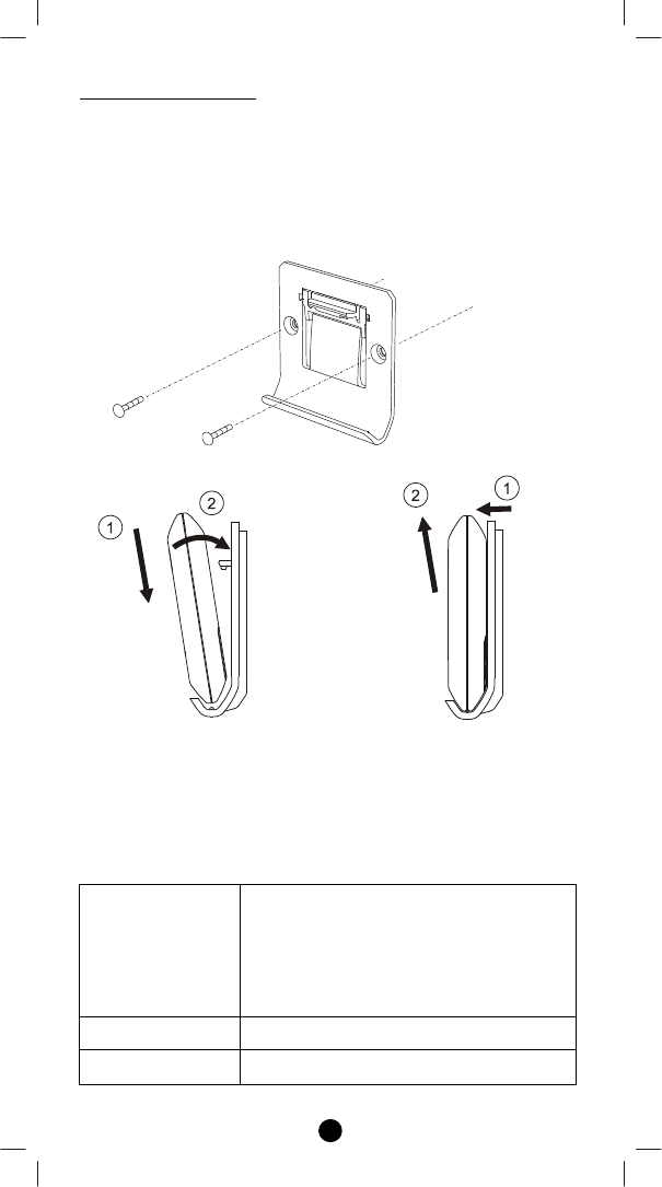
MOUNTING PROCEDURE
The ZRC-90 can be mounted to a wall or wooden racks using the two
key holes in the wall bracket.
Notes:
1. The RF reception sensitivity and transmit power are varies
depending on the antenna direction.
2. Before mounting to a wall, be sure to fully read the precautions.
Mount to the wall bracket Dismount from wall bracket
Figure 3 Installation
Technical Specifications
Model no.
BW8
5
1
0
U
S
(
ZRC
-
90
U
S
)
BW8510NA
BW8511US
BW8511NA
BW8500US
BW8500NA
RMZ3103
RF frequency 908.42MHz (ZRC-90US)
LED indication Blue
15
RF operating distance
up to
1
32
ft
(
4
0m)
out
door line of sight, in
unobstructed environment
Powered by Dry battery AAA x 2pcs
Temperature
O
peration: 0
to
40°C
Storage: -20 to 60°C
Humidity 20 to 85%, non-condensing
Dimension 110mm x 70mm x 13.5mm
Weight
6
0g (main unit and batteries excluded)
15g (wall mount bracket)
Checking Accessories
After opening the cover of the packing box, check that the following
accessories are included.
ZRC-90 Scene Master
Plastic insert
Wall mount bracket
Wall anchor x 2pcs
Screw x 2pcs
User Manual
Warranty sheet
Scene label sheet
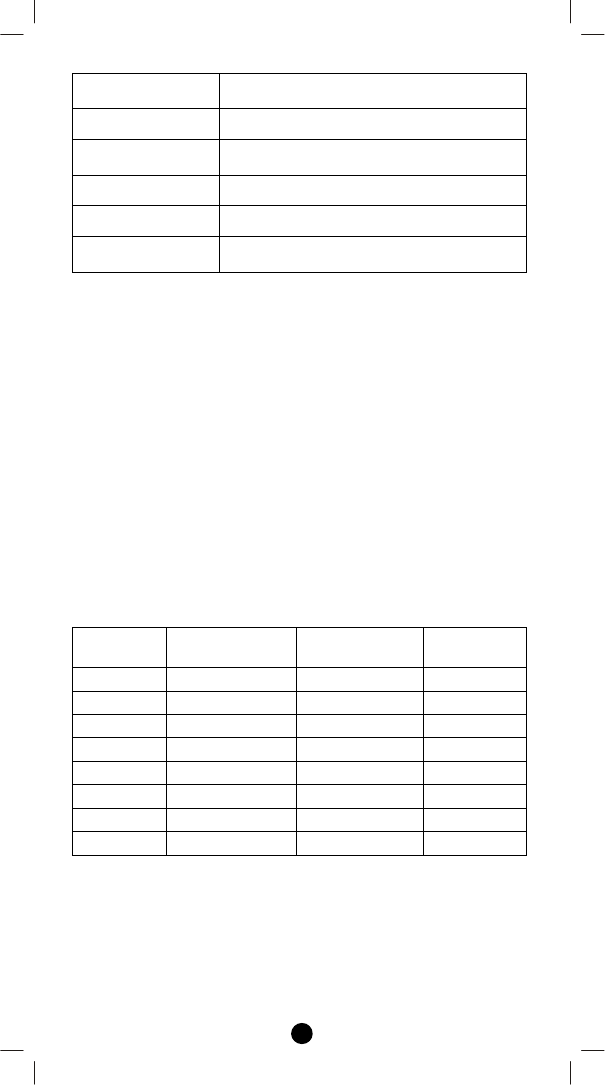
Scene Reference List
Scene
Button
Action in
single click
Action in
double click
Remark
1
2
3
4
5
6
7
8
(Please write down the scene action in case you need further reference
in the future.)
Wireless Information
This device has an open-air line-of-sight transmission distance of 132
feet (40m) which complies with the Z-Wave standards. Performance

16
can vary depending on the amount of objects in between Z-Wave
devices such as walls and furniture. Every Z-Wave device set up in
your network will act as a signal repeater allowing devices to talk to
each other and find alternate routes in the case of a reception dead
spot.
Radio frequency limitations:
1. Each wall or object (i.e.: refrigerator, bookshelf, large TV, etc) can
reduce the maximum range of 65 feet (20m) by up to 20 to 30%.
2. Plasterboard and wooden walls block less of the radio signal then
concrete, brick or tile walls which will have more of an effect on
signal strength.
3. Wall mounted Z-Wave devices will also suffer a loss of range if
they are housed in metal junction boxes which could also reduce
the range by up to 20 to 30%.
Maintenance
1. Do not expose your unit to dust, strong sunlight, humidity, high
temperatures or mechanical shocks.
2. Do not use old and new batteries together as old batteries tend to
leak.
3. Do not use corrosive or abrasive cleansers on your unit.
4. Keep the unit dust free by wiping it with a soft, dry cloth.
5. Do not disassemble the unit, it contains no user-serviceable parts.
FCC Notice
This device complies with Part 15 of the FCC rules. Operation is
subject to the following two conditions:
(1) this device may not cause harmful interference, and
(2) this device must accept any interference received, including
interference that may cause undesired operation.
Note: This equipment has been tested and found to comply with the
limits for a Class B digital device, pursuant to Part 15 of the FCC Rules.
These limits are designed to provide reasonable protection against
harmful interference in a residential installation. This equipment
generates, uses and can radiate radio frequency energy and, if not
installed and used in accordance with the instructions, may cause
harmful interference to radio communications. However, there is no
guarantee that interference will not occur in a particular installation. If
this equipment does cause harmful interference to radio or television
reception, which can be determined by turning the equipment off and
on, the user is encouraged to try to correct the interference by one or
more of the following measures:
- Reorient or relocate the receiving antenna.
- Increase the separation between the equipment and receiver.
- Connect the equipment into an outlet on a circuit different from
that to which the receiver is connected.

17
- Consult the dealer or an experienced radio/TV technician for help.
Notice: Changes or modifications to this unit not expressly approved
by the party responsible for compliance could void the user authority
to operate the equipment.
Warnings
- Do not modify the unit in any way.
- Risk of fire.
- Risk of electrical shock.
- Risk of burns.
- Do not dispose of electrical appliances and unsorted municipal
waste, use separate collection facilities. Contact your local
government for information regarding the collection systems
available.
- There is no user serviceable parts in this unit.
- Use only power supplies listed in the user instructions.
Caution
- Risk of explosion if battery is replaced by an incorrect type.
- Dispose of used batteries according to the instructions.
F820
-
8
5
1
0
-
00
00
Printed in China