Renault Clio Cup Users Manual ManualsLib Makes It Easy To Find Manuals Online!
Clio Cup clio_cup
2015-02-10
: Renault Renault-Clio-Cup-Users-Manual-360706 renault-clio-cup-users-manual-360706 renault pdf
Open the PDF directly: View PDF ![]() .
.
Page Count: 69

USER MANUAL
E. Chassis

2010 Release
E-2
4 CHASSIS
CONTENTS
4 CHASSIS 2
4.1 SETUP 3
4.2 FRONT AXLE 4
4.2.1 PRESENTATION AND CHARACTERISTICS 4
4.2.2 GEOMETRY INSPECTION 7
4.2.3 GEOMETRY VARIATIONS 9
4.2.4 ADJUSTMENT OF GEOMETRY 10
4.2.5 FRONT LOAD-BEARING COMPONENTS 11
4.2.6 WHEEL PASSAGES 20
4.3 REAR AXLE 22
4.3.1 PRESENTATION AND CHARACTERISTICS 22
4.3.2 GEOMETRY VARIATIONS 24
4.3.3 ADJUSTMENT OF GEOMETRY 25
4.3.4 REAR LOAD-BEARING COMPONENTS 26
4.4 STEERING 29
4.4.1 STEERING UNIT 29
4.4.2 INTERMEDIATE SHAFT 33
4.4.3 STEERING COLUMN 34
4.4.4 ELECTRIC POWER SYSTEM 36
4.5 BRAKING SYSTEM 39
4.5.1 CHARACTERISTICS 39
4.5.2 FRONT BRAKES 41
4.5.3 REAR BRAKES 44
4.5.4 BRAKING CIRCUIT 48
4.6 WHEELS AND TYRES 54
4.6.1 CHARACTERISTICS 54
4.7 KIT EVO 2009 55
4.7.1 NEW WISHBONE MOUNTING 55
4.7.2 EXTERNAL MIRRORS 57
4.7.3 DIFFUSER 57
4.7.4 FRONT HEADLIGHTS 58
4.7.5 FRONT BUMPER 59
4.8 TIGHTENING TORQUES 63
2010 Release
E-3
4.1 SETUP
The following Clio Cup settings apply with a 70kg driver and 40kg of fuel on board.
1,528mm
110mm
22mm
-3°10'
-3°10'
-0°10'
53kg 53kg -0°10'
6°20' 6°20'
11°15' 317kg 317kg 11°15'
75N/mm
75N/mm
35mm
370kg 370kg 35mm
2
,
585mm 2.0 ba
r
-2°30'
-2°30'
38kg 38kg 0°10'
-
-
-
172kg 172kg -
130N/mm
130N/mm
50mm
210kg 210kg 50mm
1520mm
210mm
-
Castor angle
Pivot
Spring
Stop
Rear right wheel
Rear left wheel
Camber
Stop
Alignment
(+ opening)
Camber
Ty
re
p
ressure
when warm
Alignment
(+ opening)
Castor angle
Wheel base
Pivot
Spring
Front right wheel
Castor angle
Pivot
Stop
Stop
Body height at front
Front anti-roll bar
Unsprung mass
Front track
Camber
Camber
Front left wheel
Alignment
(
+ o
p
enin
g)
Alignment
(+ opening)
Spring
Spring
Castor an
g
le
Pivot
Rear track
Body height at rear
Rear anti-roll bar
T
otal mass
Sprung mass
Unsprung mass
T
otal mass
Sprung mass
CLIO CUP 2009 BASIC SETTINGS
2010 Release
E-4
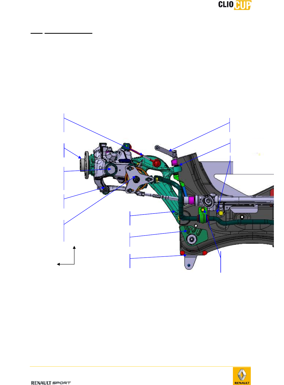
4.2 FRONT AXLE
4.2.1 PRESENTATION AND CHARACTERISTICS
The front axle is a double axis strut type suspension system.
Anti-rotation tie-
rod
Point F’:
Pivot/pivot-
holde
r
l
QQ’ tie-rod
Point P
Anti-roll bar
bearing
Point P
’
Point F:
Upper shock absorber
mountin
g
Point H
Hub
Point A
Point B
x-
y-axis
Anti-roll bar
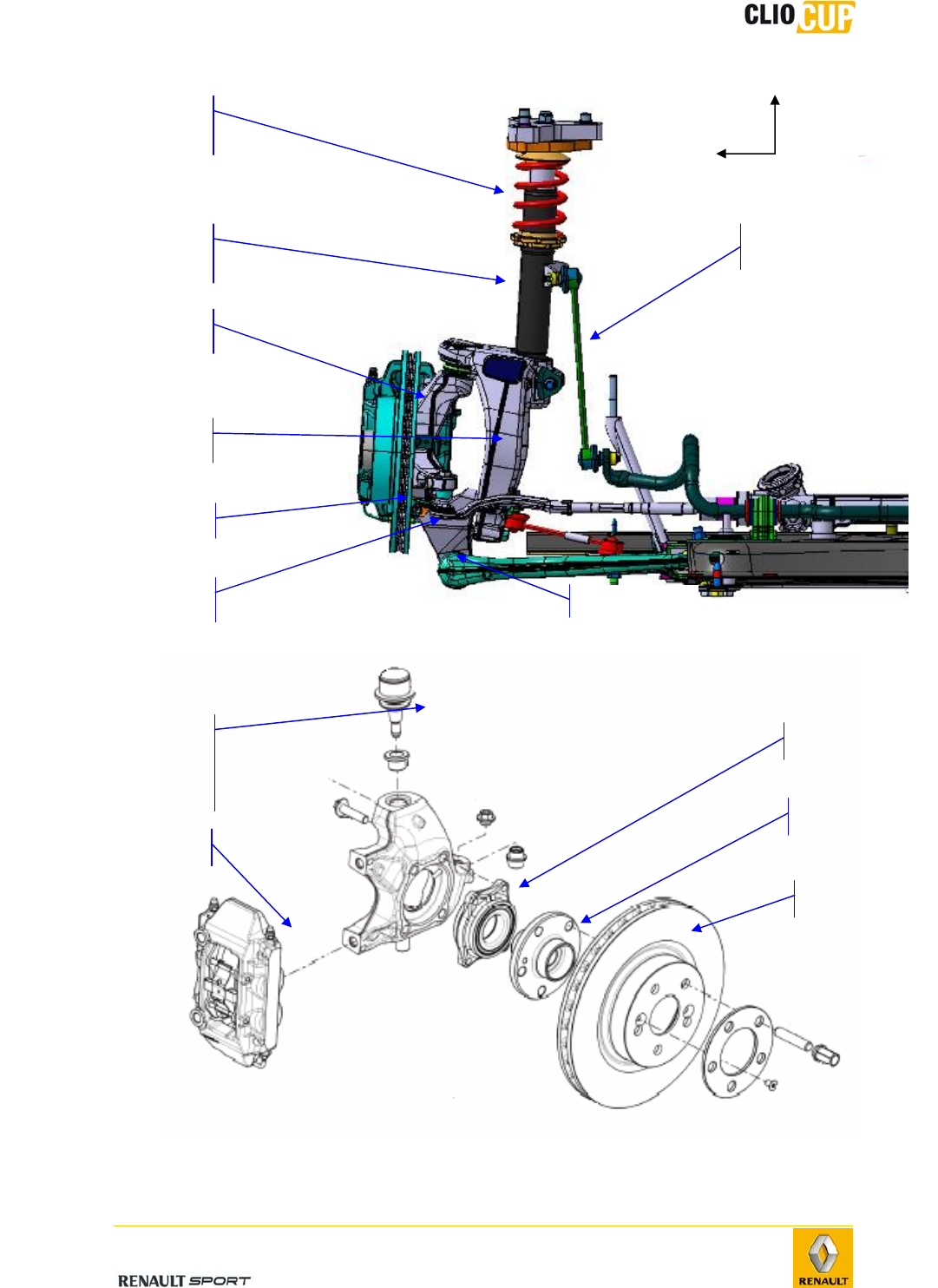
2010 Release
E-5
Point E
EE’ support
Anti-roll
bar tie-rod
Support
strut
Pivot
Damper system
z
-
axis
y-axis
Point E’ bolt
Pivot holde
r
Calipe
r
Point F’:
Pivot to pivot
holder mounting
ball joint
Roller bearing
Disk
Hub
2010 Release
E-6
Hinges
Wishbones (6):
• Subframe side: by ball joint link.
• Wheel side: by ball joint link.
Upper pivot and shock absorber: by ball joint link.
Suspension
Suspension spring: 75N/mm.
Bump stop
• length: 35mm,
• diameter: 34mm.
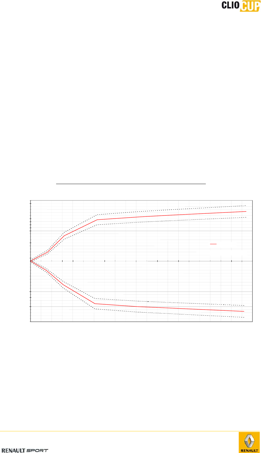
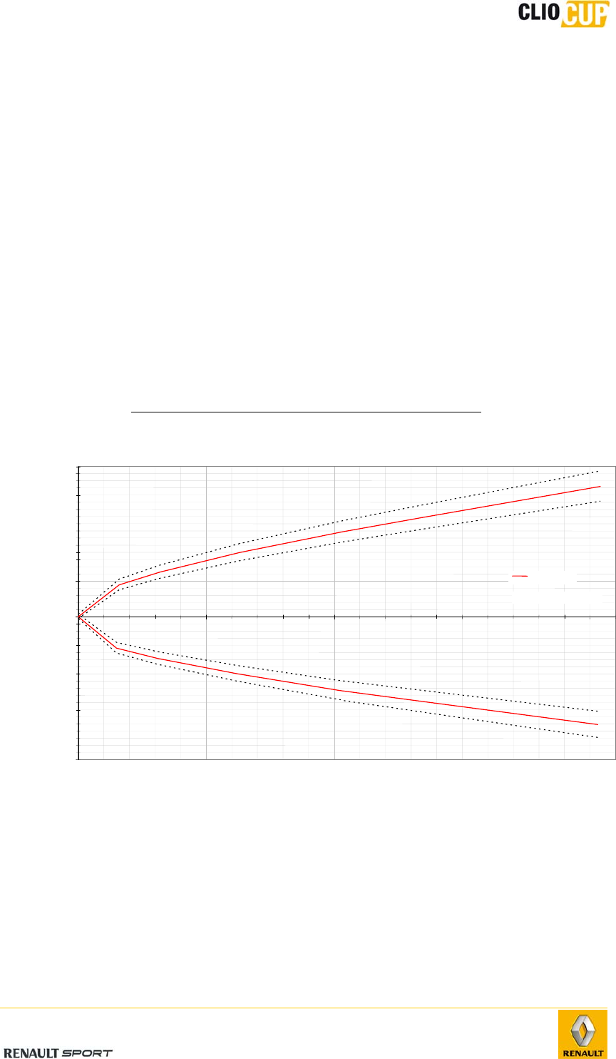
Damping
The shock absorbers are not adjustable, they must not be opened.
They are provided with seal paint. The lack of, or damage to this paint can be considered
as a technical non-compliance.
Effect of shock absorber movement speed on stress
-200
-150
-100
-50
0
50
100
150
200
0
0.05
0.1
0.15
0.2
Speed
[
m/s
]
Force
[
daN
]
---- : Tolerance
: Nominal
2010 Release
E-7
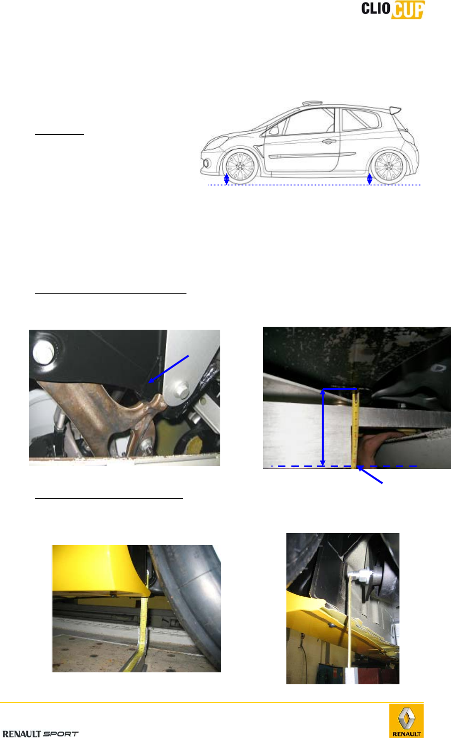
4.2.2 GEOMETRY INSPECTION
Body height measurement
points
- Conditions
Body height measurement is
performed:
With the driver on
board.
On a flat surface.
With 50L of fuel in the
tank.
With new or identically
worn tyres.
Tyre pressure at 2 bars.
- Measuring the front body height
The front body height is measured at the level of the lower front wishbone mounting (1).
- Measuring the rear body height
The rear body height is measured at the level of the rear axle point A bolt.
1
Ground projection
under subframe
Front
body
height
Rear
body
height
2010 Release
E-8
Angle inspection
- Preliminary checks
Before checking the axle angles, check (and correct if necessary) the following points:
Tyre symmetry on a given axle:
• Pressure
• Wear
Hinges:
• Condition of flexible bearings
• Ball joint clearance
• Bearing clearance
Wheel run-out (max. 0.3mm)
Body and cup height symmetry
- Front axle diagnostics
Incident Possible cause(s)
Faulty castor angle - Distorted wishbone
- Distorted side member or subframe-axle
Camber + pivot correct overall, but:
- Individual faulty camber
- Individual pivot wrong.
- Distorted wishbone
- Distorted side member or subframe-axle
Camber correct, but faulty pivot - Distorted pivot
Pivot correct, but faulty camber - Distorted pivot
Faulty variation in wheel alignment - Steering unit mounting on subframe
Wheel alignment off by more than 6mm - Distorted left or right-hand hub carrier
2010 Release
E-9
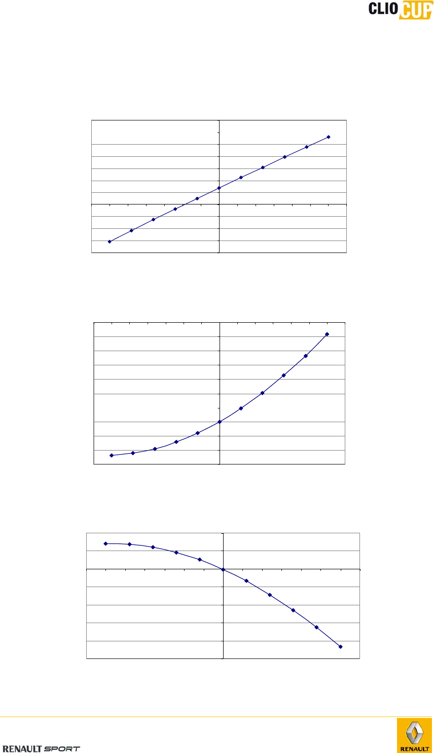
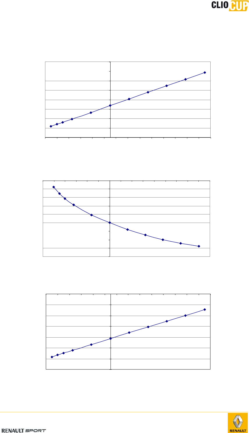
4.2.3 GEOMETRY VARIATIONS
Roll center height variation
-80
-60
-40
-20
0
20
40
60
80
100
120
140
-35 -30 -25 -20 -15 -10 -5 0 5 10 15 20 25 30 35
Suspension travel (mm)
0mm for 110 mm body height
Roll center height (mm)
Compression Rebound
Per-wheel camber variation
-3,65
-3,6
-3,55
-3,5
-3,45
-3,4
-3,35
-3,3
-3,25
-3,2
-3,15
-35 -30 -25 -20 -15 -10 -5 0 5 10 15 20 25 30 35
Suspension travel (mm)
0mm for 110 mm body height
Camber (°)
Compression Rebound
Per-wheel alignment variation
-0,25
-0,2
-0,15
-0,1
-0,05
0
0,05
0,1
-35 -30 -25 -20 -15 -10 -5 0 5 10 15 20 25 30 35
Suspension travel (mm)
0mm for 110 mm body height
Alignment (°)
ReboundCompression
2010 Release
E-10
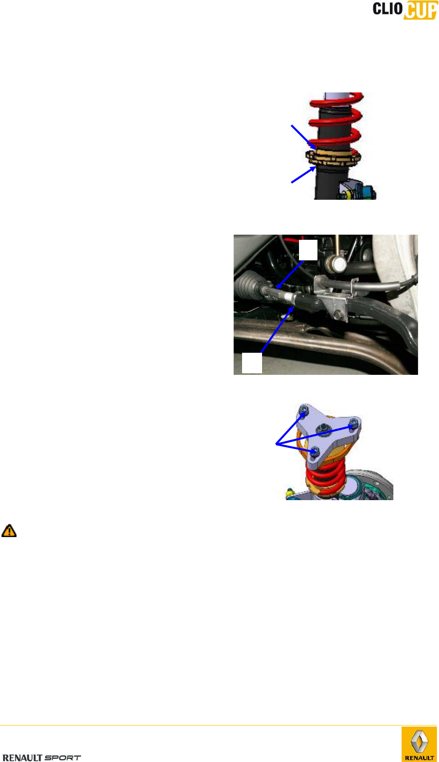
4.2.4 ADJUSTMENT OF GEOMETRY
Body height
Body height is adjusted using the nut (1)
mounted on the support strut.
Loosen the locknut (2).
Adjust body height by tightening or
loosening the nut.
Once the required height has been reached,
tighten the locknut.
Wheel alignment
Adjust the clip by means of the steering
tie-rod (1).
Loosen the locknut (2).
Adjust the alignment by tightening or
loosening the steering tie-rod.
One the required setting achieved,
tighten the locknut to 53Nm.
Camber
Adjust the camber by means of the upper
shock absorber mounting (point F).
Loosen the 3 plate bolts (1).
Adjust the camber.
Tighten the 3 bolts to 100Nm.
To avoid disconnecting the front left-hand drivetrain, driving with less than 3°
negative camber (more than -3°) on the front left-hand wheel is prohibited.
2
1
1
2
1
2010 Release
E-11
4.2.5 FRONT LOAD-BEARING COMPONENTS
Support strut
Since 2009 february the 1st , the damper tube 77 11 160 015 has been replaced by a
new reference 77 11 162 518
The mechanicals characteritics of the material and the shape of the part have been
modified to avoid plastic deformation of the damper tube
Remarque= these geomatrical modifications don’t have any incidence on the car
behaviour
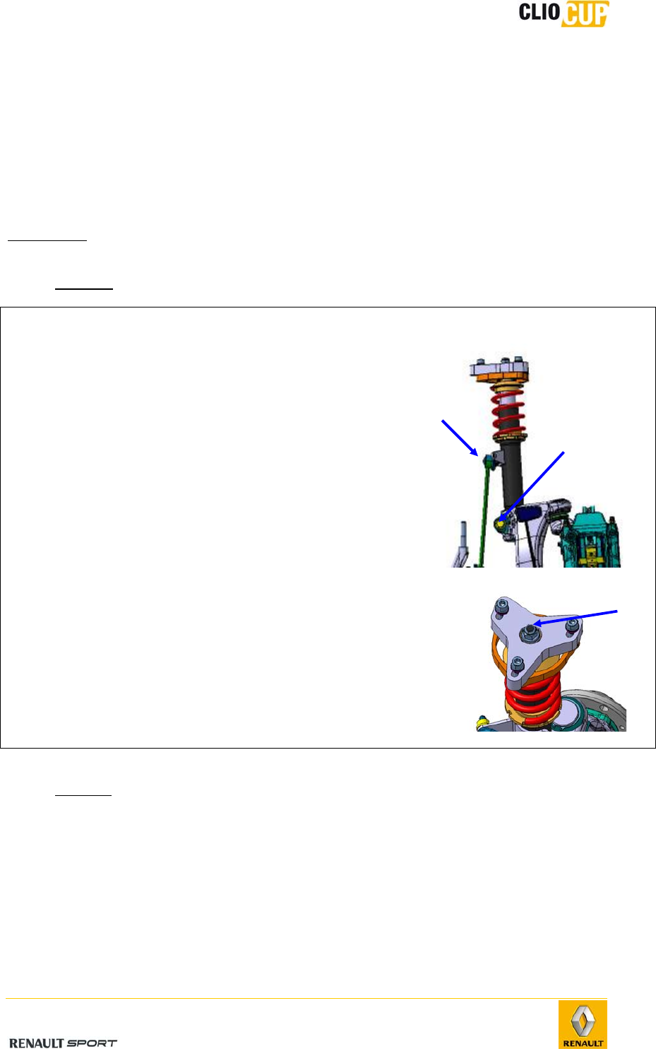
- Removal
Operations Photos
1 -
Remove the wheel.
2 -
Remove the upper mounting nut (2) of the anti-roll
bar tie-rod.
3 -
Remove the support strut mounting bolt (1) on the
pivot holder.
4 -
Extract the pivot-holder support strut.
5 -
Attach the pivot holder in the wheel arch to avoid
damaging the brake hose.
6 -
Remove the upper mounting nut (3).
7 -
Remove the fitted support strut.
- Refitting
Perform the operations in the reverse order of removal, taking care not to damage the
drivetrain bellows.
Tightening torques:
Support strut mounting bolts on pivot holder (1): 105Nm.
Upper shock absorber nut (3): 105Nm.
Anti-roll bar tie-rod mounting nut on support strut (2): 44Nm.
1
2
3
2010 Release
E-12
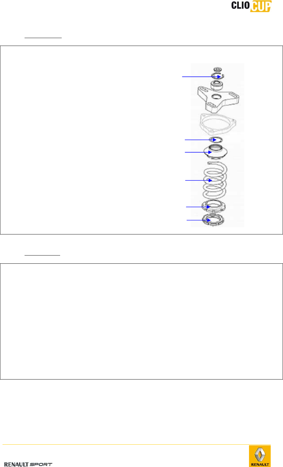
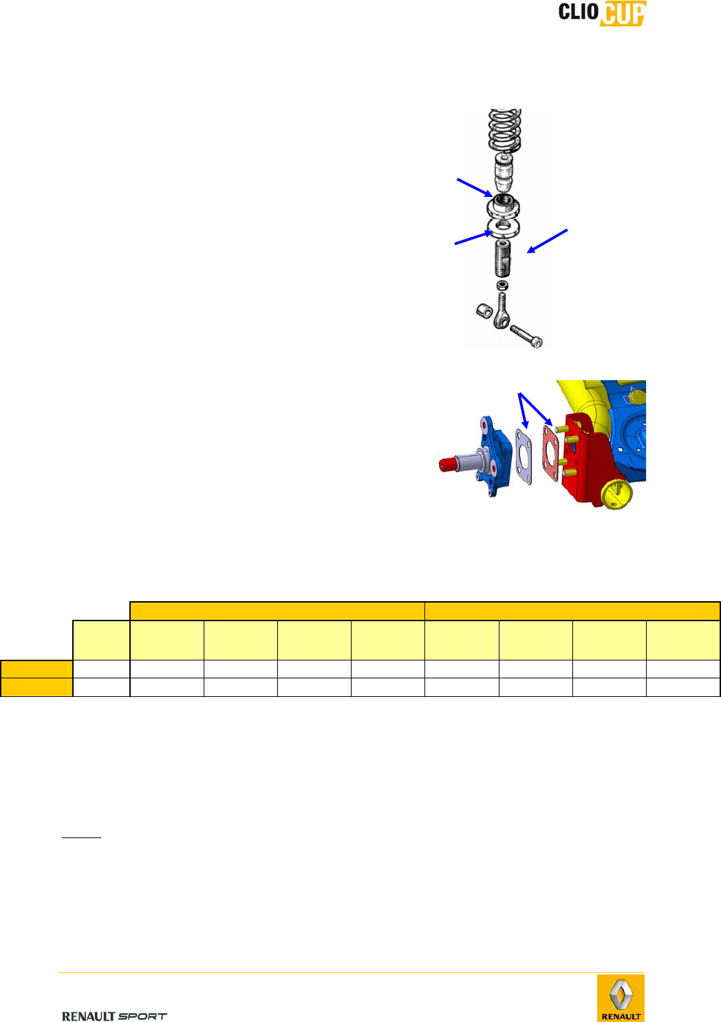
- Disassembly
Operations Photos
1 -
Remove the upper nut, holding the shock
absorber with a hexagonal socket wrench.
2 -
Remove the snap ring (1).
3 -
Loosen the nut (5) and locknut (6) so that
the spring is relaxed (3).
4 -
Remove the retainer ring (2) from the
spring cup.
5 -
Remove the suspension spring cup (3).
6 -
Remove the suspension spring (4).
7 -
Unscrew the support strut shock absorber
rod
- Reassembly
Operations
1 -
Thoroughly clean the inside of the support strut and shock absorber cartridge.
2 -
Replace the filters (ref 77 11 156 541) where necessary.
3 -
Position the bump stop (ref 77 11 160 290) on the shock absorber rod.
4 -
Lubricate the shock absorber cartridge with Bilstein grease (ref 77 11 126 744).
5 -
Proceed in reverse removal order.
6 -
Tighten the upper shock absorber nut to 105Nm.
1
2
4
5
6
3
2010 Release
E-13
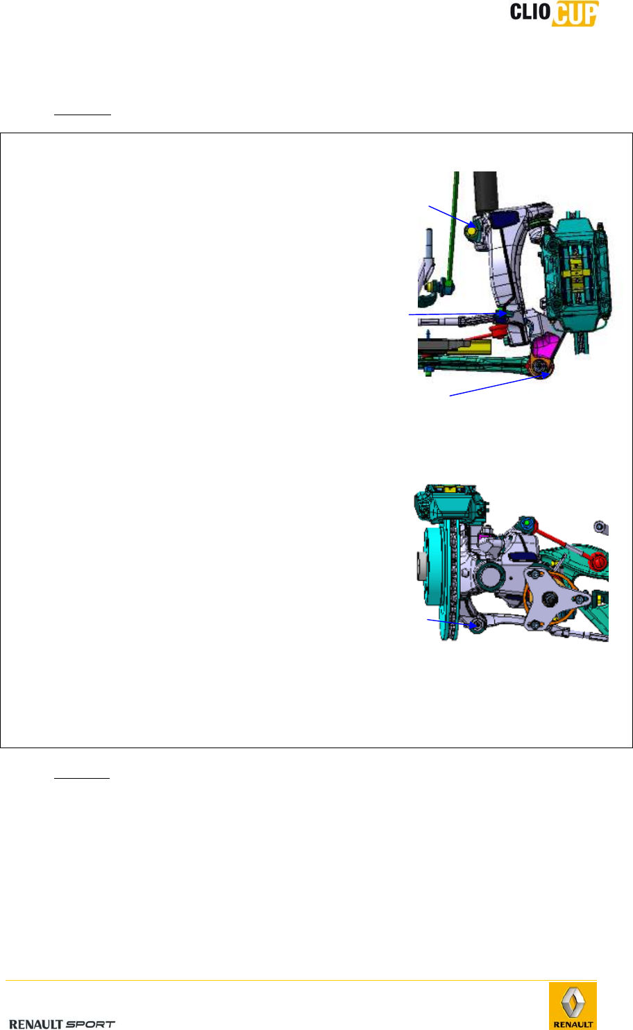
Pivot holder
- Removal
Operations Photos
1 - Remove the wheel.
2 - Remove the brake caliper (see 4-5 Brake
system/Front brakes/Calipers) and attach it in
the wheel arch.
3 - Remove the point E nut (1).
4 - Extractsupport EE' from the point E ball joint; a
ball joint puller must be used to do this.
5 - Remove the anti-roll bar mounting nut from the
pivot holder(3).
6 - Disconnect the steering rod at the level of point
H (4).
7 - Remove the wheel speed sensor at the level of
the pivot.
8 - Remove the support strut mounting bolt (2)
on the pivot holder.
9 - Extract the pivot-holder support strut.
10 -
Remove the pivot-holder, pivot and EE’ support
assembly.
11 -
Remove the EE’ support (see following section)
12 -
Remove the nut from point F’.
13 -
Remove the pivot from the pivot holder using a
ball joint puller.
- Refitting
Perform the removal steps in reverse order.
Tightening torques:
Support strut mounting bolt: 105Nm.
Anti-rotation tie-rod nut: 100Nm.
Point E nut : 105Nm.
EE’ support mounting bolt on pivot holder: 105Nm.
Point F' ball joint nut: 140Nm.
2
3
1
4
2010 Release
E-14
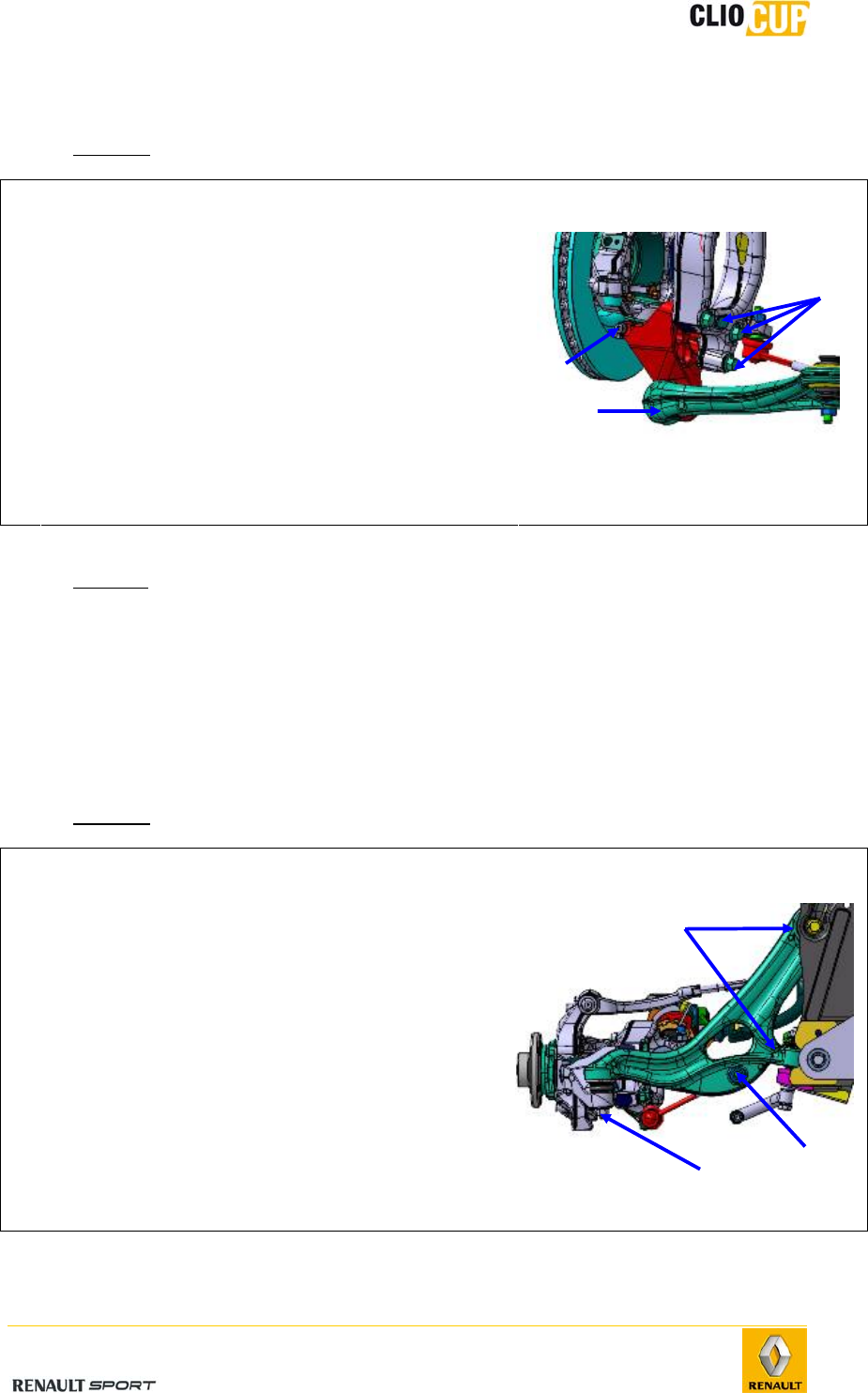
EE’ support
- Removal
Operations Photos
1 -
Remove the wheel.
2 -
Remove the point E nut (1).
3 -
Extract the EE' support from the point E ball joint;
a ball joint puller must be used to do this.
4 -
Remove the point E’ ball joint mounting bolt (2).
5 -
Remove the 3 EE’ support mounting bolts on the
pivot holder (3).
6 -
Remove the EE’ support.
- Refitting
Perform the removal steps in reverse order.
Tightening torques:
Point E’ mounting bolt: 26.5Nm.
3 pivot holder mounting bolts: 105Nm.
Point E nut: 105Nm.
Wishbone
- Removal
Operations Photos
1 -
Remove the attachment (1) of the anti-roll bar
at the level of the wishbone.
2 -
Remove the point E nut (2).
3 -
Extract support EE' from the point E ball joint;
a ball joint puller must be used to do this.
4 -
Remove the two wishbone mounting bolts (3)
on the subframe.
5 -
Remove the wishbone.
2
3
1
3
2 1
2010 Release
E-15
- Refitting
Perform the removal steps in reverse order.
Check front axle geometry and adjust if necessary.
Note: The wishbone mounting bolts on the subframe should be tightened when
the vehicle is completely static.
Tightening torques:
Point E nut: 105Nm.
Wishbone point A bolt: 80Nm.
Wishbone point B bolt: 80Nm.
Wishbone ball joints
In case of replacement, the new part
must be fitted in the same position: the
shoulder area of the A casing must rest
on the wishbone machined surface (1).
In case of replacement, the new part must
be fitted in the same position: the shoulder
area of the B casing must rest on the
wishbone machined surface in order to
permit the fitting of the snap ring (1).
Front of vehicle
1
1
2010 Release
E-16
Subframe
- Removal
Operation Photos
1 - Remove the intermediate shaft (see 4-4 Steering/Intermediate shaft).
Note: Do not turn the wheel when the shaft is not connected to the steering unit.
2 - Remove the connecting torque rod.
3 - Place a hydraulic plate in contact under the
subframe.
4 - Remove the wheel speed sensors (2) at the
level of the pivots and disconnect them from
the support (3) on the steering tie-rod.
5 - Remove the point E nuts (4).
6 - Extract the EE' support from the point E ball
joint; a ball joint puller must be used to do
this.
2
3
4
2010 Release
E-17
7 - Disconnect the anti-rotation tie-rods at the
level of the wishbones (5).
8 - Disconnect the steering tie-rods at the level
of points H (6).
9 - Disconnect the anti-roll bar tie-rods at the
level of the support struts (7).
10 - Disconnect the QQ’ tie-rods at the body level
(8).
11 -
Remove the bolts from points P (9) and P’
(10).
12 -
Extract the subframe by lowering the
hydraulic plate.
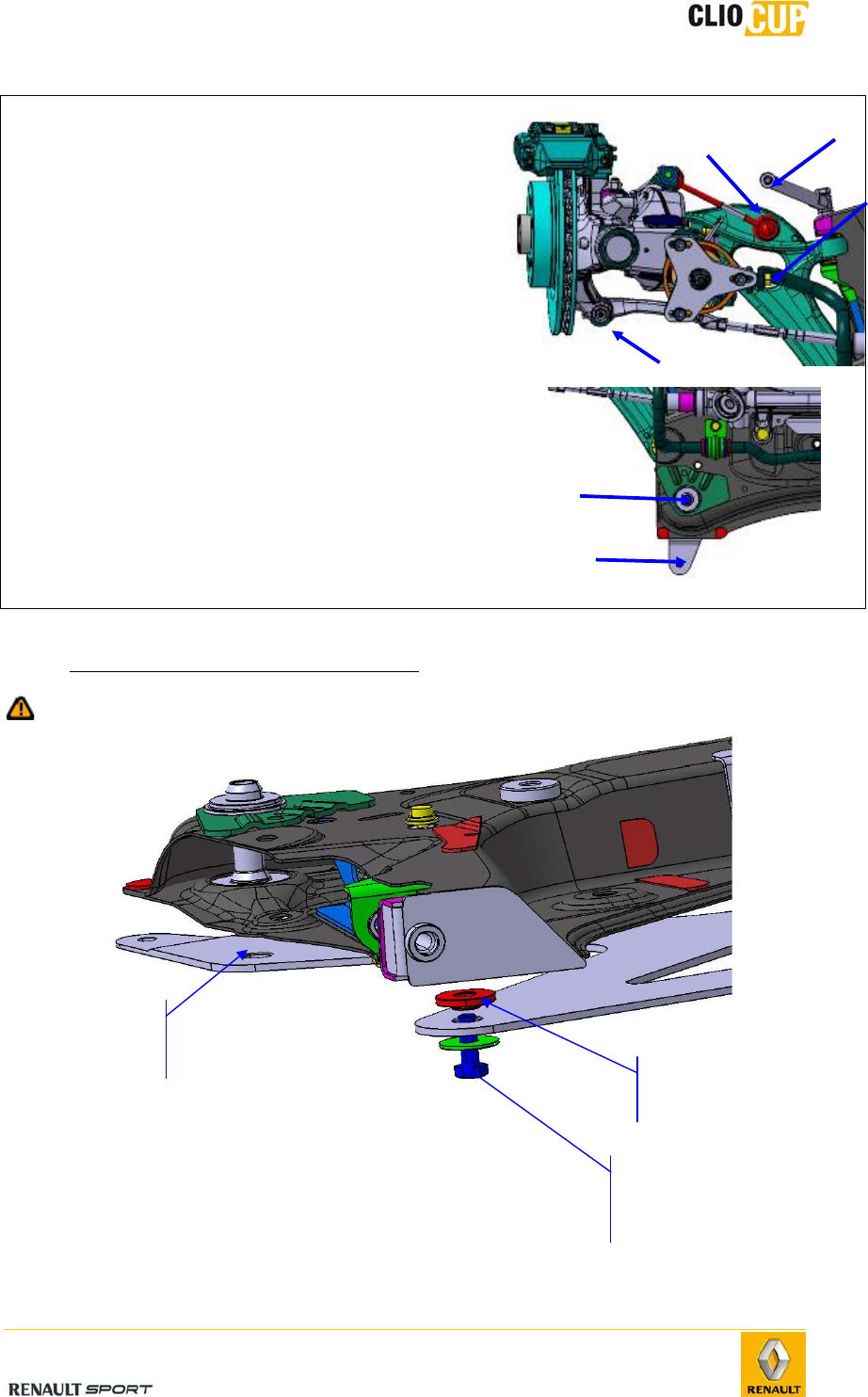
- Preparing the subframe before refitting
Do not forget the subframe braces and steering unit riser shims.
Aluminum
reinforcement plate
ref.
77 11
160 151
Bolt ref.:
77 11,156,911
+ washer
Spacer:
ref 77 11 160 184
6
8
5
7
9
10
2010 Release
E-18
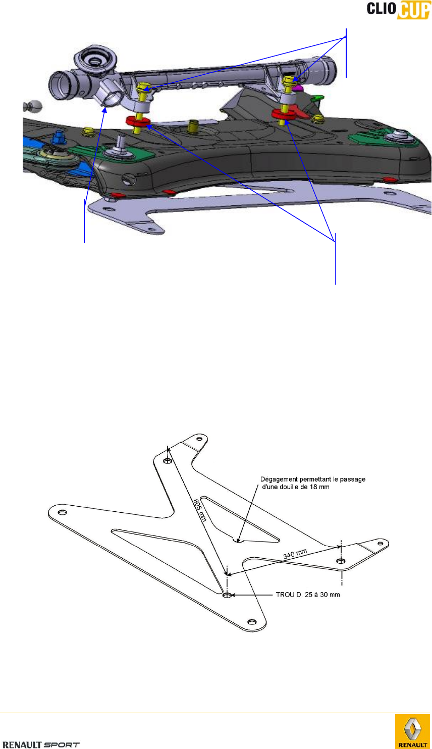
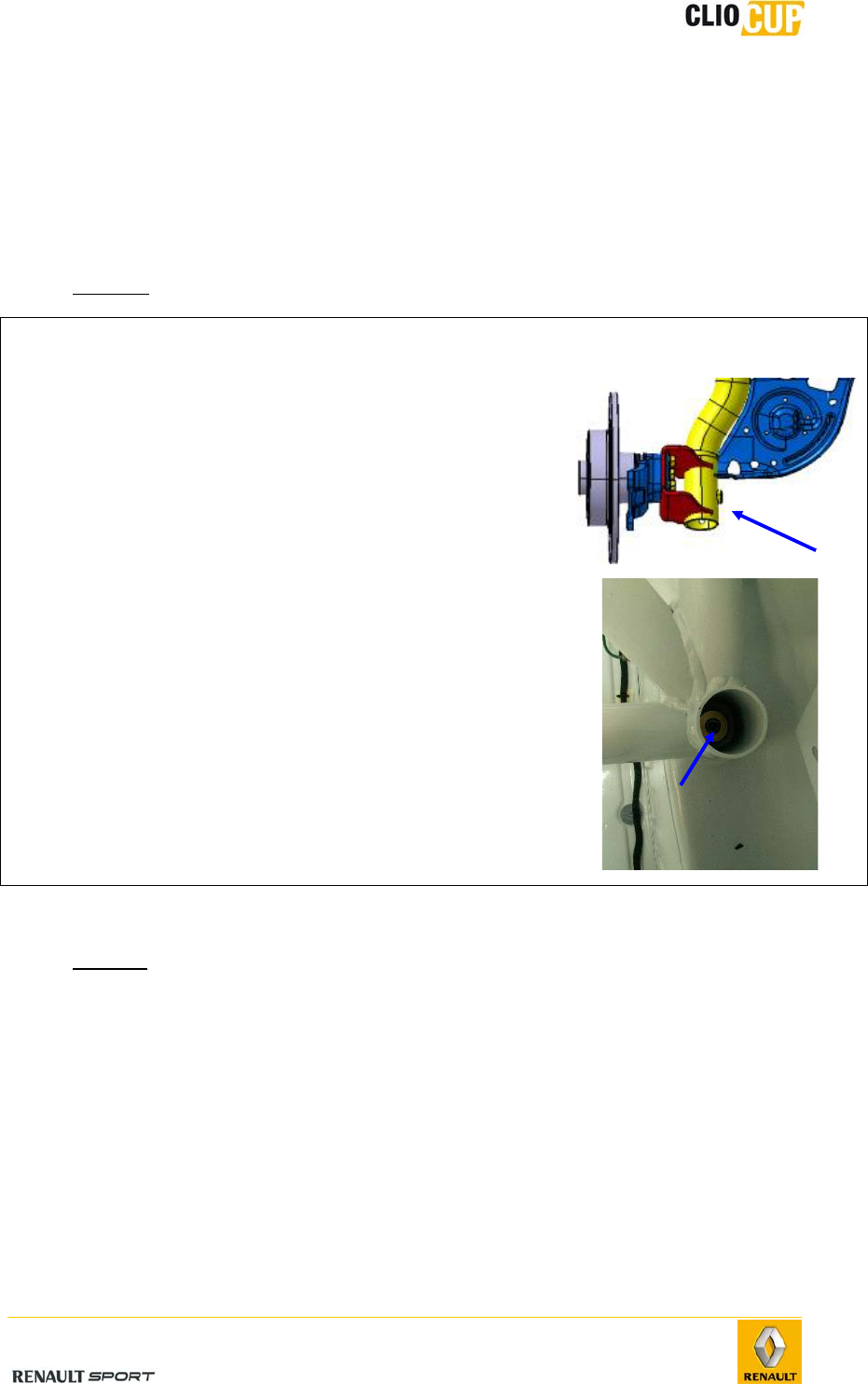
To allow :
- The differential casing-oil change,
- An access to the fixation screw of the rear powertrain support rod:
It is allowed to modify the subframe reinforcement plate as below,
1) Drill a ø 25 to 30 mm hole below the draining stopper of the differential casing
2) Carry out a clearing around the screw head to allow the access of a 6 sides
bushing (18mm)
Any other modification is not allowed
Steering unit
ref.: 77 11 160 046
Steering unit mounting
bolt
ref.: 77 03 602 136
Steering unit riser
shims
ref.: 77 11 160 016
2010 Release
E-19
- Refitting
Perform the removal steps in reverse order.
Tightening torques:
Bolts for points P and P’: 120Nm.
QQ’ mounting bolts to body: 105Nm.
Anti-roll bar tie-rod mounting bolt: 44Nm.
Point H nut: 37Nm.
Anti-rotation tie-rod mounting bolt on wishbone: 100Nm.
Point E nut: 105Nm.
Connecting torque rod mounting bolt on yoke: 105Nm.
Connecting torque rod mounting bolt on subframe: 105Nm.
Anti-roll bar
- Removal
Operations Photos
1 -
Remove the anti-roll bar tie-rod mounting nuts
(1) at the level of the anti-roll bar.
2 -
Remove the subframe (see. 4-2 Front axle/Front
load bearing components/Subframe).
3 -
Remove the bar support bearings (2).
4 -
Remove the bar.
5 -
Check the condition of the bearings and replace if
necessary.
- Refitting
Perform the removal steps in reverse order.
Tightening torques:
Anti-roll bar bearing mounting bolts: 21Nm.
Anti-roll bar tie-rod mounting nuts: 44Nm.
2 1
2010 Release
E-20
4.2.6 WHEEL PASSAGES
The wheel passages are in 2 parts, a rear one and a front one.
1
Cut out the rear wheel passages like
on the photograph
2
Fit the wheel passages
2010 Release
E-21
Perform the assembly steps in reverse order to remove it.
3
Fix the plastic mounting clamps (right
side on photograph)
4
Tight this 3 screws
behind the wheel
under the protective moulding
5
Fix a plastic collar between the front
wheel passage and the plastic plate
for engine protection
2010 Release
E-22
4.3 REAR AXLE
4.3.1 PRESENTATION AND CHARACTERISTICS
The rear axle has combined swingshafts.
Calipe
r
Axle
Shock absorber
mountin
g
bolt
Hub carrier
Disc
Bearing
mounting bolt on
Bearing
Mounting bolt
on rear axle
(point A)
2010 Release
E-23
Hinges
Lower: by ball joint.
Upper (shock absorber): by ball joint.
Suspension
Suspension spring: 130N.
Bump stop:
• length: 50mm
• diameter: 31mm.
Damping
The shock absorbers are not adjustable, they must not be opened.
They are provided with seal paint. The lack of, or damage to this paint can be considered
as a technical non-compliance.
Effect of shock absorber movement speed on stress
-
200
-
150
-
100
-
50
0
5
0
10
0
15
0
20
0
00.0
5 0.
1
0.1
5
0.
2
Speed [m/s]
Force
[daN]
---- :
Tolerance
:
Nominal
2010 Release
E-24
4.3.2 GEOMETRY VARIATIONS
Roll center height variation
114
115
116
117
118
119
120
121
122
-55 -45 -35 -25 -15 -5 5 15 25 35 45 55 65 75 85
Suspension travel (mm)
0 mm for 110 mm body height
Roll center height (mm)
ReboundCompression
Per-wheel camber variation
-2,08
-2,06
-2,04
-2,02
-2
-1,98
-1,96
-1,94
-1,92
-1,9
-60-50-40-30-20-100 102030405060708090
Suspension travel (mm)
0 mm for 110 mm body height
Camber (°)
ReboundCompression
Per-wheel alignment variation
-0,7
-0,6
-0,5
-0,4
-0,3
-0,2
-0,1
0
-55 -45 -35 -25 -15 -5 5 15 25 35 45 55 65 75 85
Suspension travel (mm)
0mm for 110 mm body height
Alignment (°)
ReboundCompression
2010 Release
E-25
4.3.3 ADJUSTMENT OF GEOMETRY
Body height
Body height is adjusted using the nut (1)
mounted on the extension (2).
Loosen the locknut (3).
Adjust body height by tightening or
loosening the nut.
Once the required height has been reached,
tighten the locknut.
Alignment and camber
The alignment and camber of the rear axle are
adjusted by inserting shims (1) between the
hub carrier and the axle.
Depending on the required effect, the shims
should be positioned according to the thickest
edge.
The correspondence between the shims and their resulting alignment/camber is given
in the following table.
Camber shim Alignment shim
No
shim
10'
77 11 160
176
20'
77 11 160
175
30'
77 11 160
174
1°
77 11 160
173
10'
77 11 160
172
20'
77 11 160
171
30'
77 11 160
170
1°
77 11 160
169
Camber -1,23 -0,1 -0,19 -0,29 -0,98 -0,03 -0,05 -0,08 -0,17
Alignment 0,21 0,03 0,05 0,09 0,16 -0,1 -0,19 -0,28 -0,84
To obtain the recommended setup (see 4-1 Setup) the following shim set should be
used:
Alignment (wheel opening): one 1° shim,
Camber (wheel negative camber): one 1° shim.
Note: To achieve the same setting for both rear axle wheels, the shims used on
the left and right-hand sides may differ.
3
1
1
2
2010 Release
E-26
4.3.4 REAR LOAD-BEARING COMPONENTS
Hub
See 4-5 Brake System/Rear brakes/Hub disc.
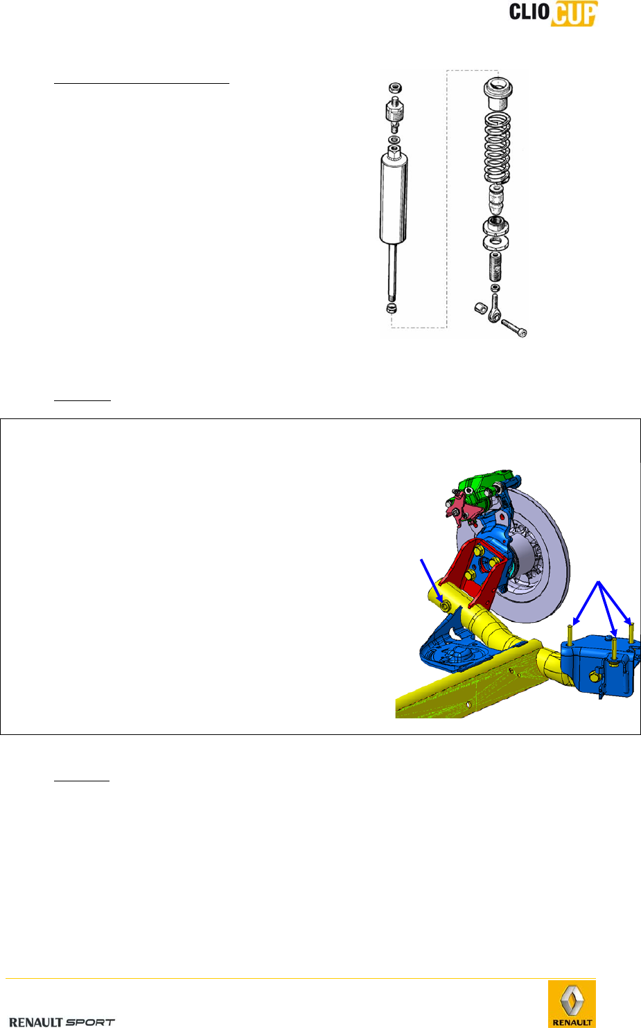
Damper system
- Removal
Operations Photos
1 -
Place the vehicle on a jack stand on the appropriate
side.
2 -
Remove the wheel.
3 -
Remove the lower mounting bolt (1).
4 -
Remove the upper mounting nut (2).
5 -
Remove the damper system.
- Refitting
Perform the removal steps in reverse order.
Tightening torques:
Lower mounting bolt: 105Nm.
Upper mounting bolt: 80Nm.
1
2
2010 Release
E-27
- Disassembly & reassembly
The disassembly & reassembly of the
damper system is performed in the same
manner as for the front axle (see 4-3
Front axle/Front load bearing
components/Support strut).
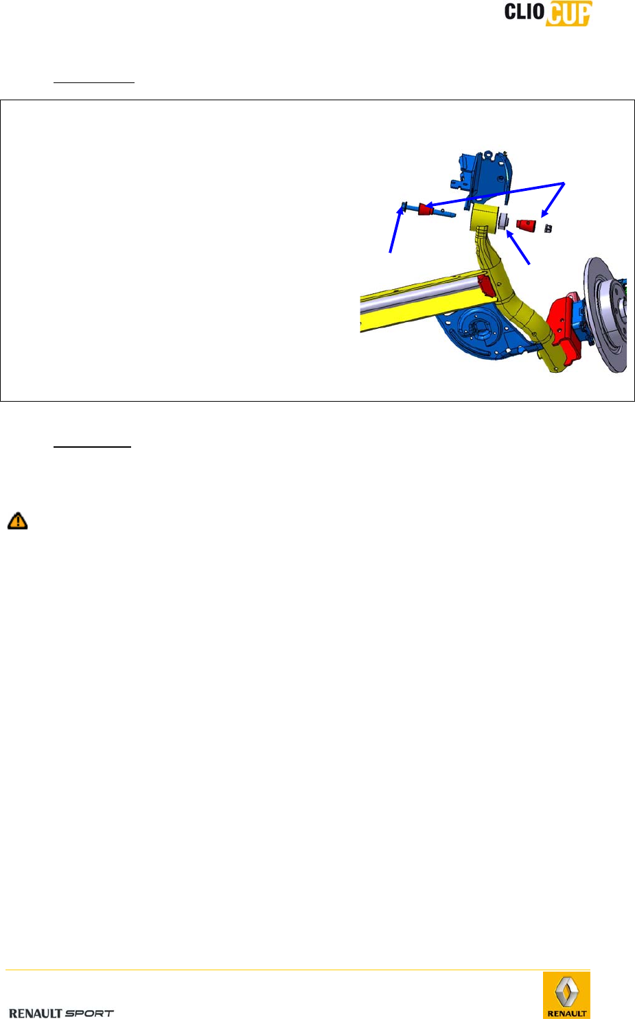
Rear axle
- Removal
Operations Photos
1 -
Place the vehicle on an auto-lift.
2 -
Remove the lower attachment (1) of the two
shock absorbers.
3 -
Remove the brake hoses from the calipers.
4 -
Support the rear axle and then remove:
The six bearing mounting bolts (2).
The rear axle.
- Refitting
Perform the removal steps in reverse order.
Tightening torques:
Lower shock absorber mounting bolt: 105Nm.
Bearing mounting bolt on body: 62Nm.
Brake hose on caliper: 14Nm.
Drain the braking circuit.
1
2
2010 Release
E-28
- Disassembly
Operations Photo
1 - Remove the point A bolt (1) and collect the
spacers (2).
2 - Remove the snap ring.
3 - Remove the ball joint from point A (3).
- Reassembly
Perform the removal steps in reverse order.
Tighten the bolt (1) to 125Nm.
Follow spacer assembly direction (2): long spacer (Ref 77 11 160 125) inside
and short spacer (Ref: 77 11 160 124) outside.
1
3
2
2010 Release
E-29
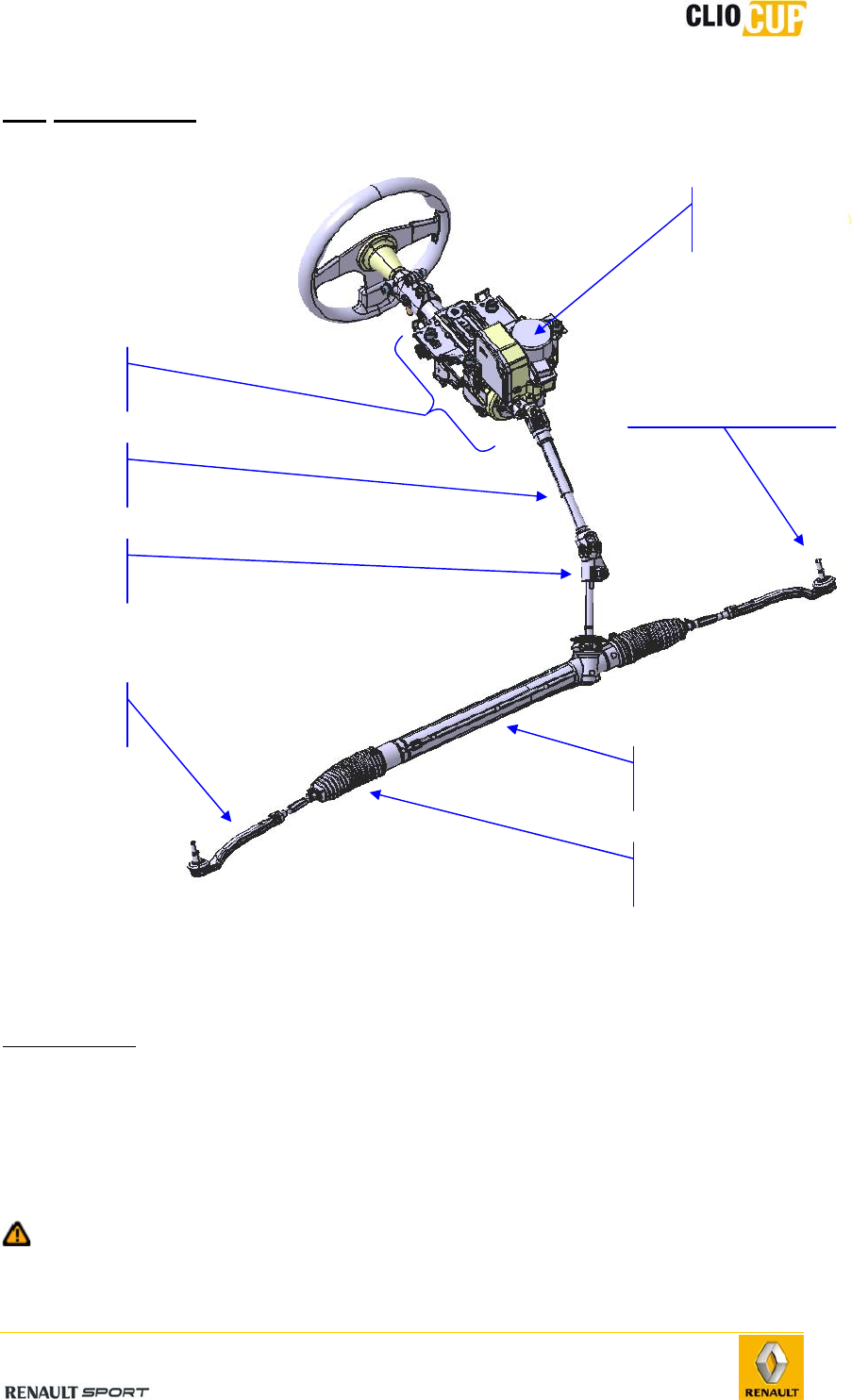
4.4 STEERING
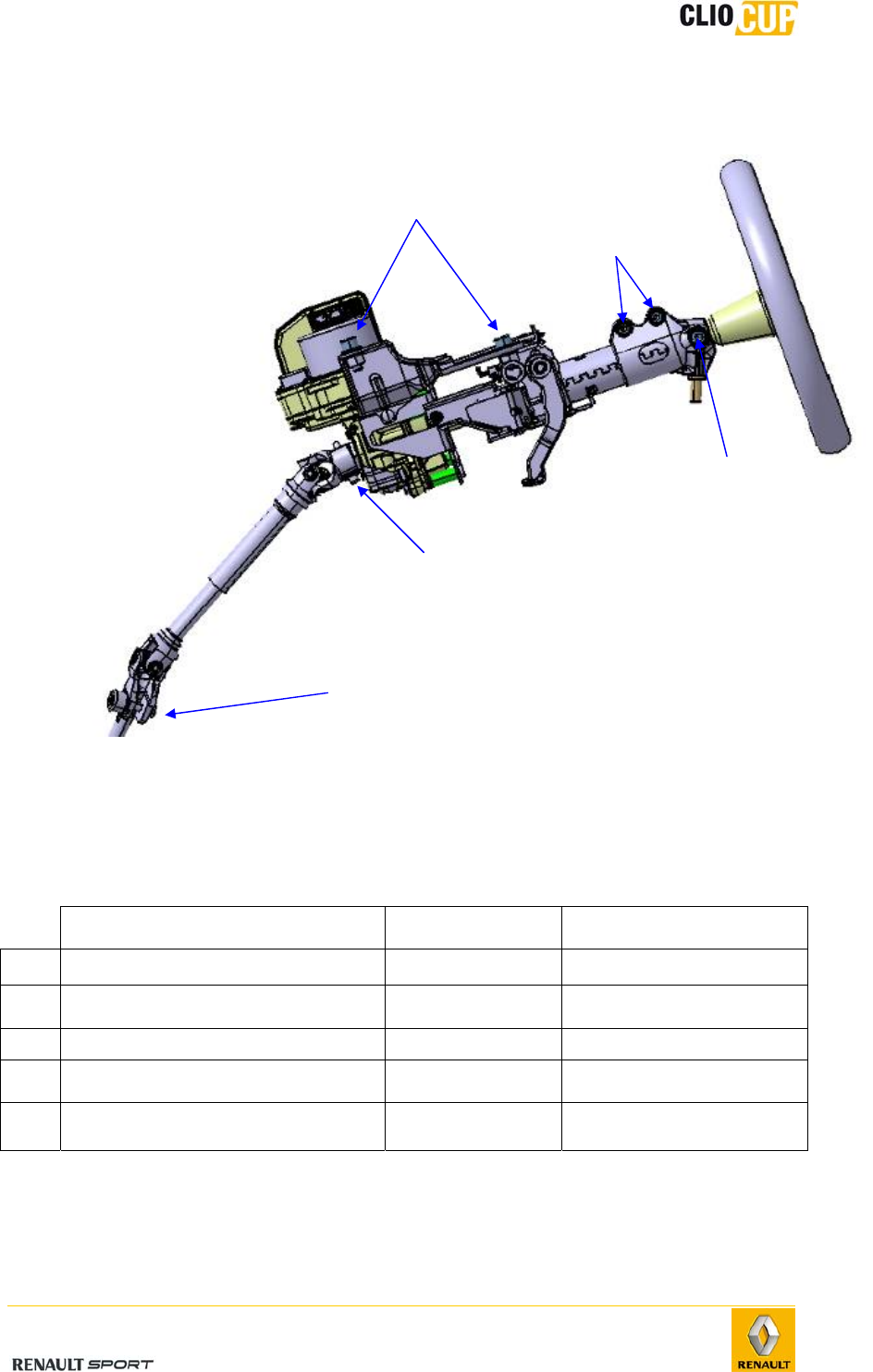
4.4.1 STEERING UNIT
Axial ball joint
Specialist tools
Dir. 1305-01 Axial ball joint removal-refitting tool.
Dir. 1741 Steering unit bar retainer tool.
TAV 476 Ball joint puller.
The axial ball joint is replaced with the steering unit in place on the vehicle. Indeed, the
Dir. 1741 or Dir. 1305-01 tool is used to connect the bar to the steering unit.
To avoid damaging the pinion teeth and steering unit bar during this operation, it
MUST be supported using the tool: Dir. 1741.
Steering tie-rod ball
joint
Power steering
module
Folding yoke
Intermediate
shaft
Steering
column
Steering unit
Bellows
Steering tie-
rod
2010 Release
E-30
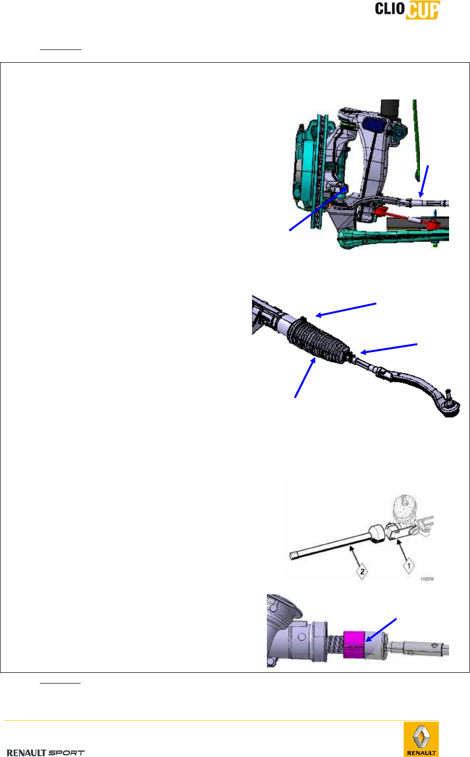
- Removal
Operations Photos
1 -
Place the vehicle on an auto-lift.
2 -
Remove the front wheel on the relevant
side.
3 -
Loosen the alignment locknut (1).
4 -
Remove the point H nut (2).
5 -
Extract the ball joint from point H using
the tool: (1) Tav. 476.
6 -
Remove the small bellows clamp (1).
7 -
Cut the large bellows clamp (2).
8 -
Unscrew the steering tie-rod counter-
clockwise and note the number of
rotations for refitting.
9 -
Remove the steering tie-rod.
10
-
Extract the bellows (3).
11
-
Unlock the steering column.
12
-
Position the tool: (1) Dir. 1741 on the
steering bar, pinion side.
13
-
Release the axial ball joint using the (2)
Dir 1305-01 tool.
14 - Remove the axial ball joint and steering
unit shim (1) (Ref 77 11 160 142).
- Refitting
1
2
1
2
3
1
2010 Release
E-31
Minimum thread installation: 1.5 times the thread diameter, i.e. 18mm of
thread engaged in the ball joint sleeve.
Perform the removal steps in reverse order.
Note: Position the steering unit shim (Ref 77 11 160 142) before fitting the
axial ball joint onto the steering unit.
Fit the bellows (see 4-4 Steering/Steering unit/Bellows)
Follow the ball joint unit markings: one mark on the right (1) and 2 on
the left (2).
Left ball joint unit Right ball joint unit
Tightening torques:
Axial ball joint on bar: 80Nm.
Point H nut: 37Nm.
Steering tie-rod locknut: 53Nm.
Steering unit
- Removal
Operations Photos
1 -
Remove the subframe (see 4-2 Front
axle/Front load bearing components/
Subframe).
2 -
Remove the two steering unit
mounting bolts (1).
3 -
Remove the steering unit and collect
the unit’s riser shims (2).
1
2
2 1
2010 Release
E-32
- Refitting
Operations
1 -
Position the riser shims on the subframe (ref 77 11 160 016, thickness: 5mm).
2 -
Fit the steering unit on the subframe.
3 -
Tighten the two bolts to 105Nm.
4 -
Refit the subframe (see 4-4 Front axle/Front load bearing components/Subframe).
Bellows
- Bellows assembly
When replacing an axial ball joint, new bellows MUST be refitted.
To ensure the good air balance, the steering MUST be placed at the mid-point.
1 -
Fit a nose cone on the axial ball joint in order to avoid damaging the bellows during
assembly.
2 -
Coat the bellows’ contact surface with the axial ball joint with grease to prevent the
bellows from twisting.
3 -
Attach the bellows with a new clamp (provided with the bellows).
2010 Release
E-33
4.4.2 INTERMEDIATE SHAFT
- Removal
Operations Photos
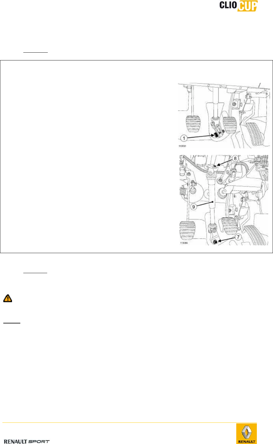
1 -
Remove the folding yoke bell (1) (discard).
2 -
Set the wheels straight.
3 -
Remove the folding yoke bolt (7) (discard).
4 -
Remove the folding yoke nut (discard).
5 -
Remove the intermediate shaft bolt (8) on the
column.
6 -
Remove the intermediate shaft (9).
- Refitting
Perform the removal steps in reverse order.
Systematically replace the folding yoke bolt (ref 77 03 602 097) and cam nut
after each removal.
Note: On a new intermediate shaft, the folding yoke cam nut is pre-assembled,
do not remove the bell.
Follow the direction of assembly of the folding yoke bolt and cam nut.
Tightening torques:
Folding yoke bolt on steering box: 24Nm.
Bolt on steering column: 32Nm.
2010 Release
E-34
4.4.3 STEERING COLUMN
- Removal
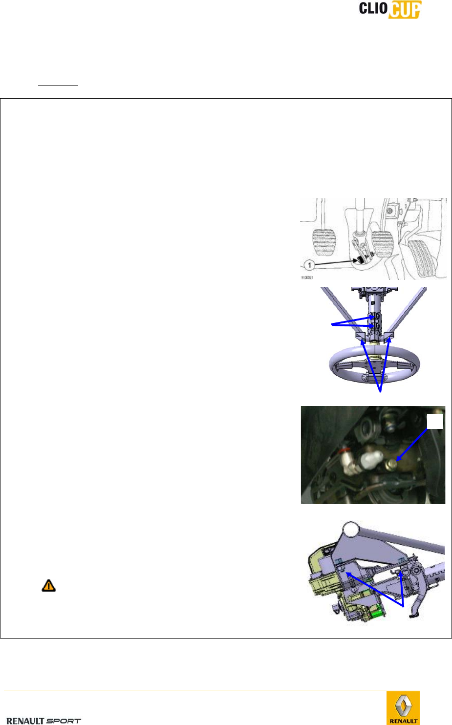
Operations Photo
1 - Set the vehicle wheels straight.
2 - Disconnect the battery's ground cable.
3 - Remove the dashboard.
4 - Disconnect the power steering wiring harness.
5 - Remove the steering wheel, followed by the wheel
hub, after marking their initial positions.
6 - Extract the bell from the folding yoke (1).
7 - Remove the 2 roll cage stay bolts (2) on the
steering sheath.
8 - Remove the 2 sheath mounting bolts (3) on the
column.
9 - Remove the column sheath.
10 - Remove the extinguisher jet attachment lug (4).
11 - Remove the 4 steering column bolts (5) on the
roll cage crossmember.
12 - Remove the column, power steering module and
intermediate shaft assembly.
It is important not to turn the wheel when
the column has been removed in order to
not offset the position sensor (see 4-4
Steering/EPS unit).
3
2
5
4
2010 Release
E-35
- Refitting
1 - Refit the steering column.
2 - Tighten the four bolts to 105Nm.
3 - Fit the folding yoke.
4 - Tighten the cam nut to 24Nm.
5 - Fit the sheath onto the column and tighten the 2 bolts to 21Nm.
6 - Tighten the 2 roll cage stay mounting bolts on the column to 21Nm.
7 - Place the steering wheel hub on the column.
8 - Tighten the hub mounting bolt to 44Nm.
9 - Fix the wheel on the hub.
10 - Connect the power steering module wiring harness.
11 - Refit the dashboard and central console.
2010 Release
E-36
4.4.4 ELECTRIC POWER SYSTEM
If the unit undergoes a heavy impact or if the vehicle is involved in an accident.
The unit MUST be sent to the Alpine after-sales service.
Transport precautions
The unit must be held in place by the shaft and engine housing.
Handling the unit using the shaft alone can cause significant damage to the torque
sensor and, consequently, can lead to unit malfunction.
Safety recommendation
The EPS system may generate significant forces and rotation speeds, which may in turn
cause injury. It is therefore important to handle it with caution, in accordance with the
maintenance guidelines (see following paragraph) and to return it to the supplier prior to
re-use if it has been damaged.
Maintenance guidelines
The condition of all of the EPS mechanical components and electrical
connections should be checked after each race.
A period of at least 20 seconds should be left between general vehicle
power cut-off and EPS disconnection to allow all internal diagnostic
procedures to complete.
The unit can reach temperatures of 85°C following repeated operations. It
is therefore necessary to check the unit’s temperature before
disassembling it.
Use
- Start-up
Ensure that the EPS is correctly connected to the wiring harness.
Turn on the vehicle's electrics (button (12) on the control panel; see 1-6
Using the car).
After a short period of time, the EPS makes a "clicking" noise. This
indicates that the unit is powered up and ready to use.
Turn the wheel. The EPS should function and the less effort should be
required to turn the wheel.
For the wheel position sensor to transmit its measurements, it must first
be calibrated. The power steering will function correctly, even if the
sensor has not been calibrated, but angle measurements will not be
available on data acquisition.
To calibrate the sensor, turn the wheel slowly to the 0° position (this
information is visible from the “Vision” software see 6 Operating
software/Vision). This position is an item of production data and may not
correspond to the vehicle’s wheels being straight. It is for this reason
that, when calibrating the sensor for the first time, the wheel must be
rotated 360°(don’t turn up to the stop!) in each direction. The 0°
position will then correspond to the straight wheels position. The system
will maintain this calibration as long as the vehicle’s electrics are on, but
will require re-calibrating to 0° on each general power cut.

2010 Release
E-37
- Power off
Before switching off completely, the system switches to “power latch” mode.
During this phase, the system checks the operation of certain components that
cannot be tested during the operating phase.
To ensure that all the tests are performed correctly, power must be
maintained for at least 30 seconds after dashboard shutdown (wait 30 seconds
between turning off the engine: using switch (12) before cutting off the
general power supply with switch (1)).
Fault diagnosis
Symptom 1: When the system is powered up, the effort required to turn the wheel
does not reduce. Furthermore, the system does not “click”.
Solutions:
Ensure that the ignition switch is in the up position (on).
Check that the wiring harness is connected to the battery and that the
battery is charged.
Check all connections between the battery, EPS and ignition switch.
Ensure that there is no power loss and that they are connected to the
correct pins.
Check that all fuses between the battery and the EPS are in working
order.
If the system is still malfunctioning after these checks, it must be immediately returned
to the Alpine after-sales service.
Symptom 2: When the steering wheel is turned, the power steering stops before
reaching full travel. When the wheel it turned in the opposite direction, however, the
power steering operates correctly to full travel.
Solution: This problem is due to the maximum rotation allowed by the system of
1600°. If the 0° position stored by the system is significantly different from the angle
of the wheels, the angle measured by the EPS may exceed the maximum value in one
direction. To solve this problem, disconnect the intermediate shaft and rotate the
wheel 360° in the direction of correct system operation. This will align the system’s
0° position with that of the wheels.
Symptom 3: When driving the vehicle, the power steering varies randomly, even
though the system is constantly powered up.
Solution: Ensure that all connections between the EPS, the battery and the ignition
switch are shielded and sealed and that there is no corrosion or dirt on them.
If these solutions fail to solve the problem, the system must be immediately returned to
the Alpine after-sales service.
2010 Release
E-38
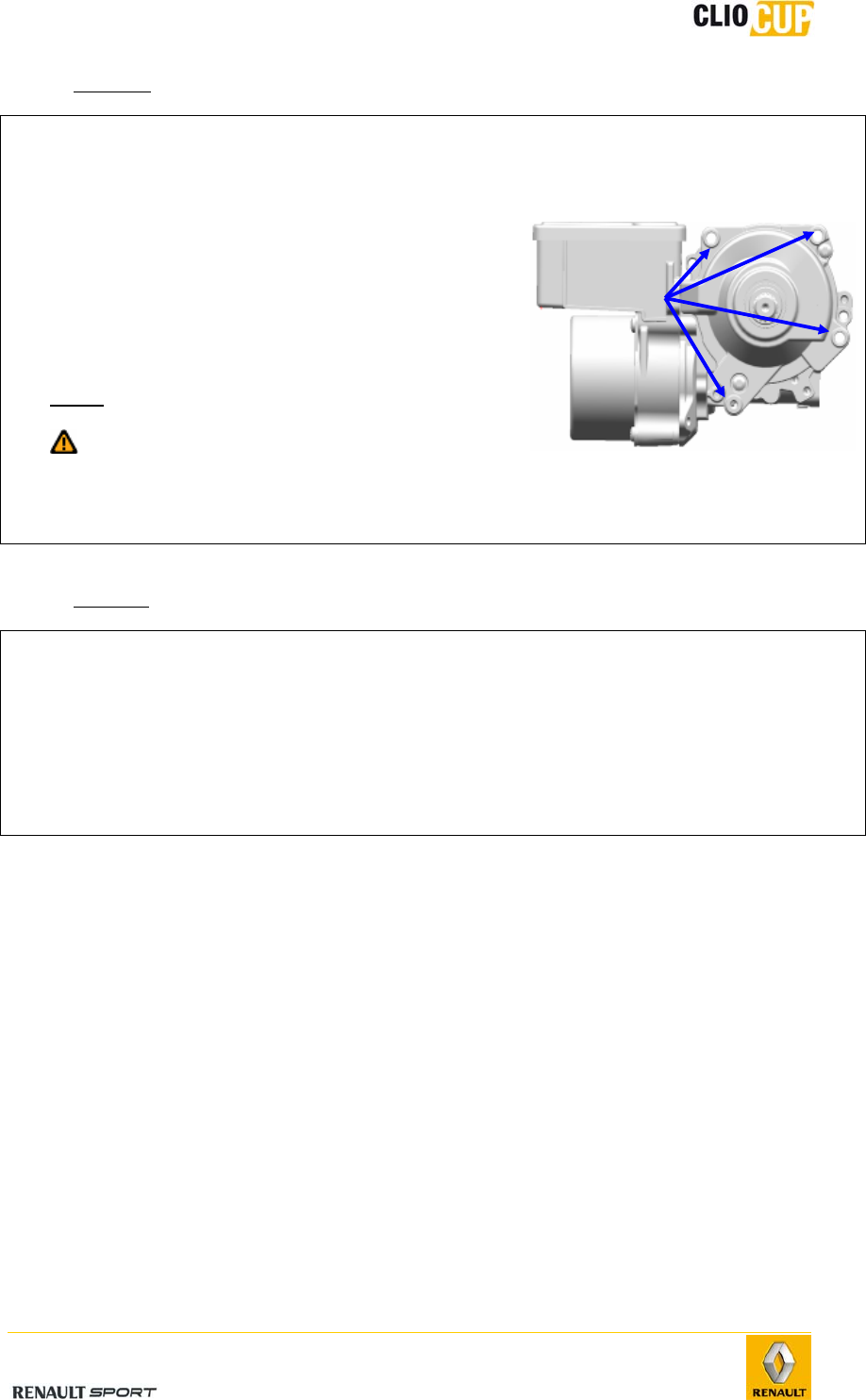
- Removal
Operations Photo
1 -
Remove the steering column (see previous
paragraph).
2 -
Remove the 4 unit mounting bolts (1) on the
steering column.
3 -
Remove the power steering module from the
column.
Note: keep the four spacers.
It is important not to run the EPS unit
when the column has been removed in
order to not offset the position sensor
(see 4-4 Steering/EPS unit).
- Refitting
Operations
1
-
Refit the power steering module on the column, using the 4 spacers (ref 77
11 160 149).
2
-
Tighten the 4 bolts (1) to 6Nm.
3
-
Refit the column (see 4-4 Steering/Steering column).
1

2010 Release
E-39
4.5 BRAKING SYSTEM
4.5.1 CHARACTERISTICS
Front brake
Clutch slave cylinder diameter: 40mm.
Disc diameter: 312mm.
Disc thickness: 28mm.
Minimum disc thickness: 26mm.
Rear brake
Clutch slave cylinder diameter: 38mm.
Disc diameter: 300mm.
Disc thickness: 11mm.
Minimum disc thickness: 9.5mm.
Master cylinder
Diameter: 23.8mm.
Brake booster
Diameter 10’’
Front brake pads
Ferodo DS 1.11
Rear brake pads
Ferodo DS 2500
2010 Release
E-40
Clio Cup is only officially approved by Renault Sport when fitted with Ferodo
brake pads.
Running in
Ferodo DS 1.11 brake pads do not require any specific running-in.
DS 2500 brake pad run-in protocol:
Clean the brake disc with Emery paper (surface in contact with the pad).
Remove all traces of previous friction.
Create a 45° chamfer on the outer circumference of the pad if the discs
are hollowed.
Perform 3 to 4 medium pressure braking operations (150 to 100kph).
Allow to cool between braking (+/-400 meters).
Perform 1 heavy pressure braking operation (180 to 100kph).
Allow to cool (+/- 800meters).
Repeat the process two or three times.
Under no circumstances during run-in should brake pad temperature exceed 300°C to
400°C.
Brake pad operation at low temperatures may lead to the build-up of friction
material on the disc. This deposit may cause vibrations when braking. Should this
occur, buff the discs to eliminate this phenomenon.
2010 Release
E-41
4.5.2 FRONT BRAKES
Brake pads
- Removal
Operations Photos
1 -
Push back the pistons.
Watch out for rising brake fluid levels in
the tank.
2 - Remove the upper spindle (1) using a drift
punch.
3 - Remove the spring and lower spindle (2).
4 -
Remove the pads, noting their position for
refitting, where appropriate.
- Refitting
Perform the removal steps in reverse order.
1
2
2010 Release
E-42
Maximum authorized contact surface with the disc
The maximum front brake pad friction material surface area tolerated on the Clio Cup is
shown on the following diagram.
Brake calipers
The brake calipers cannot be repaired. If a fault is detected on the caliper, it must
be systematically replaced.
- Removal
Operations Photos
1 -
Disconnect the banjo bolt (1) linking the hose to
the caliper (brake fluid will pour out).
2 -
Remove the brake pads (see previous paragraph).
3 -
Remove the two caliper mounting bolts (2).
4 -
Remove the caliper.
- Refitting
Operations
1 -
Fit the caliper on the pivot and attach it using its bolts (2).
2 -
Tighten to 164Nm.
3 -
Check the condition of the hose (replace if necessary) and attach with the banjo bolt.
4 -
Tighten to 14Nm.
5 -
Drain the braking circuit.
1
2
2010 Release
E-43
Disk
- Removal
Operations Photos
1 -
Push back the pistons.
Watch out for rising brake fluid levels in the
tank.
2 -
Remove the two bolts (2) holding the caliper on the
pivot.
3 -
Release the caliper and attach it in the wheel arch.
Do not damage the hose (1).
4 -
Remove the two disc mounting bolts (3).
5 -
Remove the track shim and the disk.
- Refitting
Operations
1 -
Fit the disc onto the hub.
2 -
Fit the track shim (ref 77 11 160 154).
3 -
Fix the assembly with two new bolts and tighten to 21Nm.
4 -
Refit the brake caliper and tighten to 164Nm.
5 -
Press the brake pedal several times in order to place the piston in contact with the
pads.
1
2
3
2010 Release
E-44
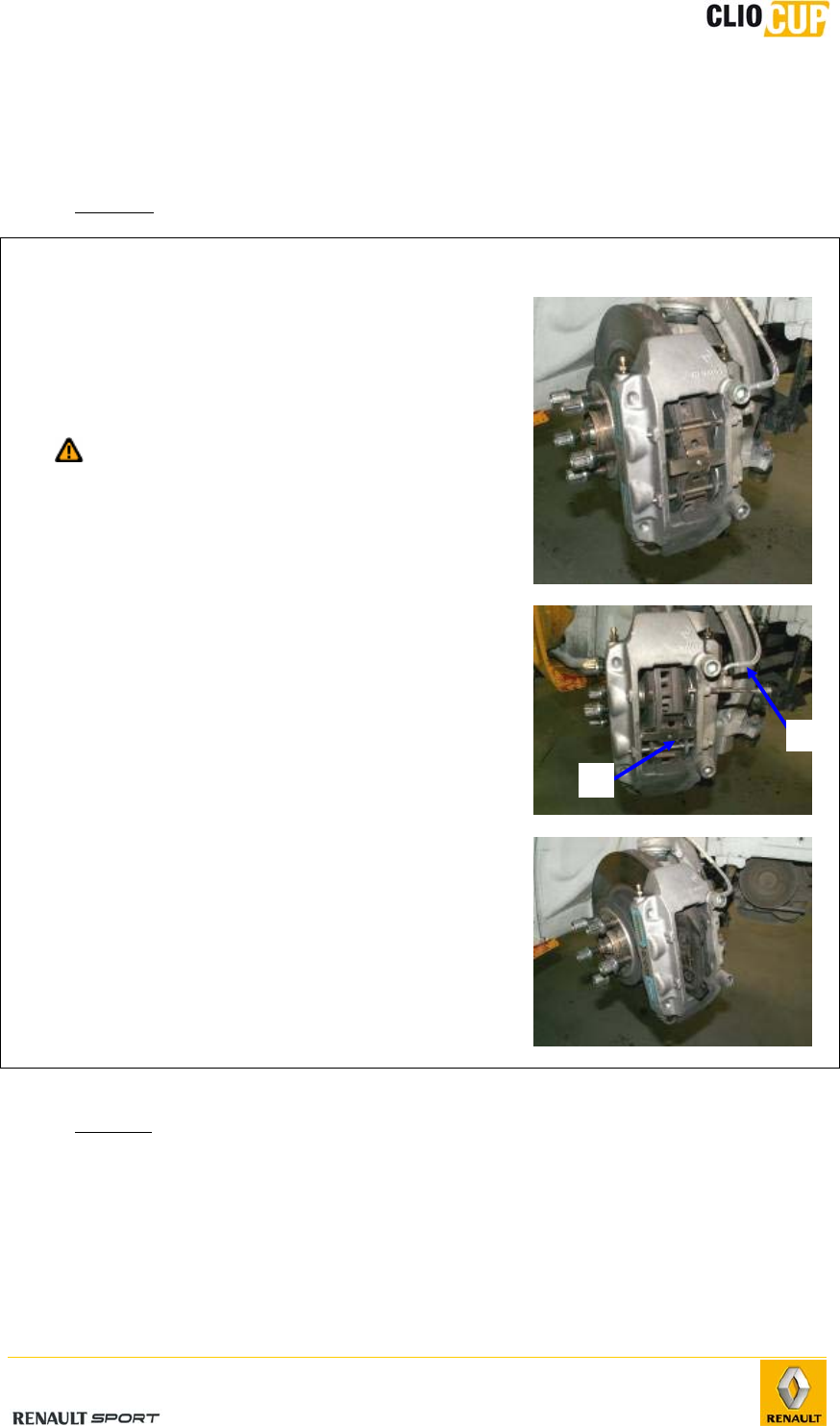
4.5.3 REAR BRAKES
Brake pads
Specialist tools:
Fre 1190-01 Brake caliper piston driver.
- Removal
Operations Photos
1 -
Remove the wheels.
2 -
Remove the lower small column mountings.
3 -
Swivel the calipers upwards.
4 -
Remove the brake pads.
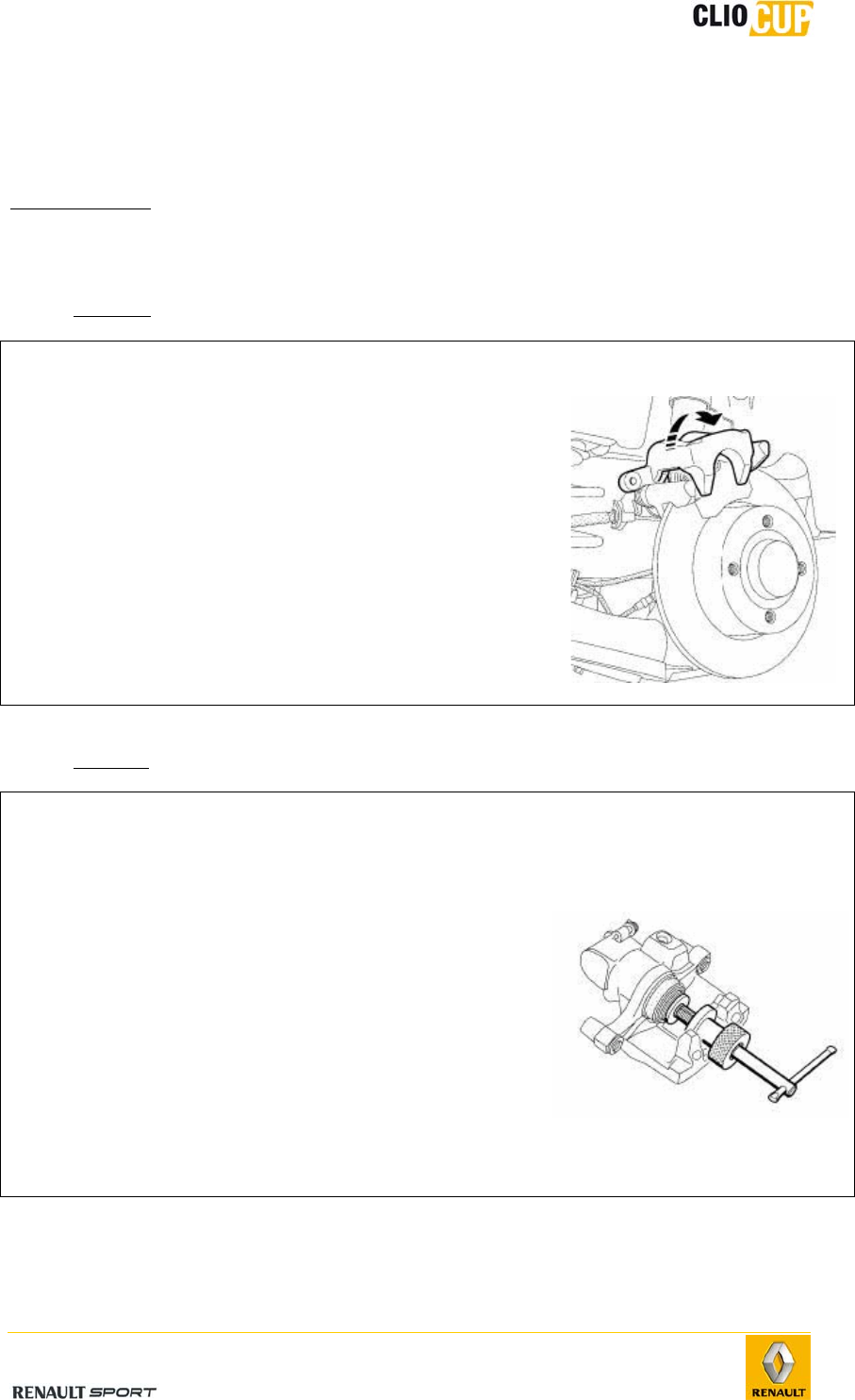
- Refitting
Operations Photos
1 -
Check pad thickness.
2 -
Clean the caliper supports and the calipers.
3 -
Push caliper piston back into its bore using the Fre
1190-01 tool.
4 -
Fit the pads.
5 -
Swivel the caliper downwards into its initial
position.
6 -
Refit a NEW small column bolt.
7 -
Tighten the small column bolt to 32Nm.
2010 Release
E-45
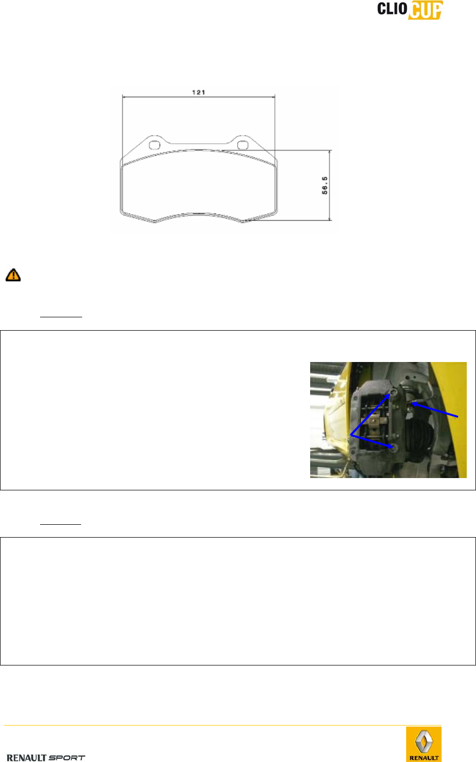
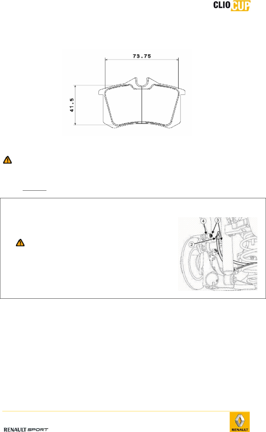
Maximum authorized contact surface with the disc
The maximum rear brake pad friction material surface area tolerated on the Clio Cup is
shown on the following diagram.
Brake calipers
The brake calipers cannot be repaired. If a fault is detected on the caliper, it must
be systematically replaced.
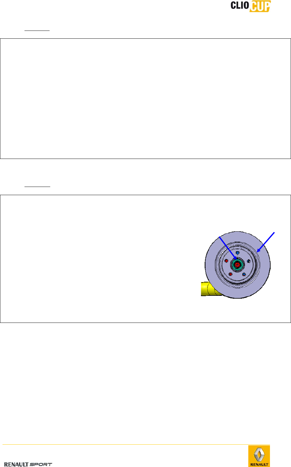
- Removal
Operations Photos
1 -
Remove the wheel.
2 -
Remove the brake hose (2).
Allow for fluid discharge.
3 -
Remove the small column mounting bolts (3) while
holding the nuts (4).
4 -
Remove the caliper.
2010 Release
E-46
- Refitting
Operations
1 - Check the condition of the caliper piston bellows.
2 - Clean the caliper support and the caliper.
3 - Refit the brake pads (see 4-5 Braking system/Rear brakes/Pads).
4 - Refit the caliper.
5 - Refit the new small column bolts.
6 - Refit the brake hose.
7 - Tightening torques:
Small column bolts: 32Nm.
Brake hose: 14Nm.
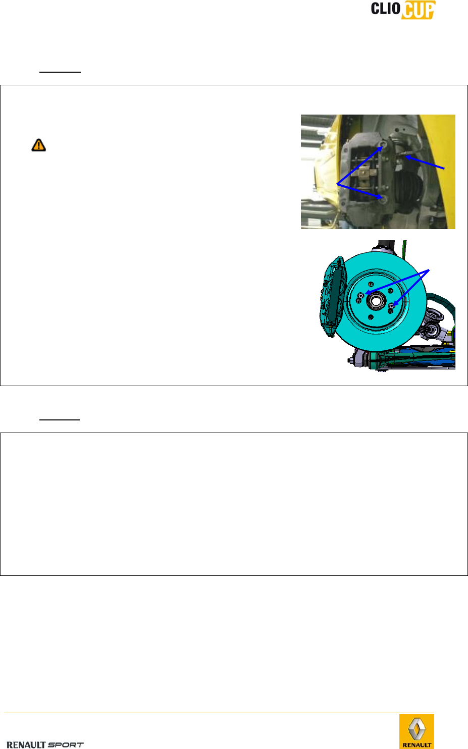
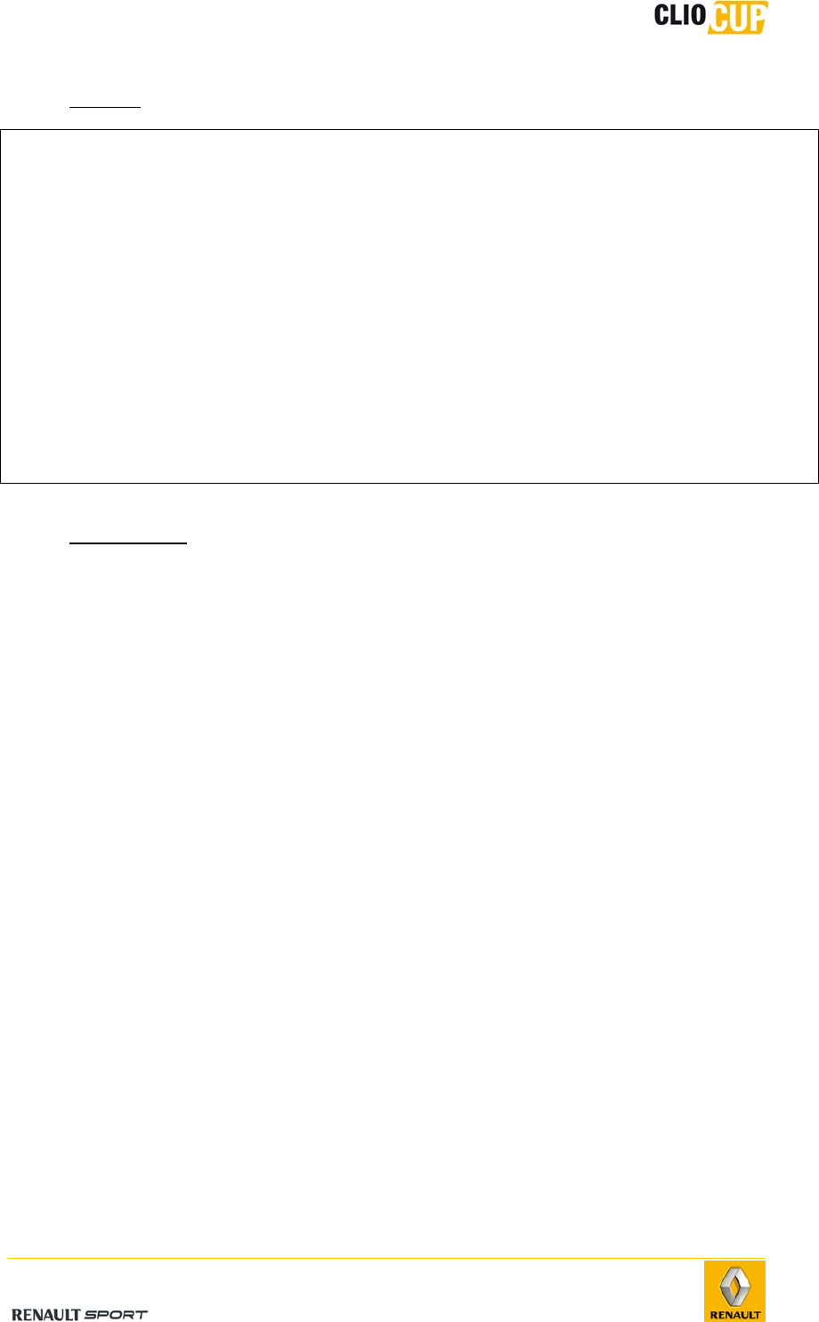
Hub disc
- Removal
Operations Photos
1 -
Release the spindle bolt (1).
2 -
Remove the wheel.
3 -
Remove the brake pads (see previous paragraph).
4 -
Remove the two brake caliper mounting bolts.
5 -
Remove the brake caliper and attach it in the wheel
arch.
6 -
Remove the spindle nut.
7 -
Remove the hub disc (2).
1 2
2010 Release
E-47
- Refitting
Operations
1 -
Fit the hub. disc (1) on the spindle.
2 -
Position the spindle bolt.
3 -
Refit the brake caliper and tighten the bolts to 105Nm.
4 -
Refit the pads (see corresponding paragraph).
5 -
Refit the wheel and tighten the bolts to 130Nm.
6 -
Tighten the spindle nut to 220Nm.
7 -
Press the brake pedal several times in order to place the piston in contact with the
pads.
- Checking play
Check axial play using a dial gauge mounted on the disc: max. 0.03 mm.
2010 Release
E-48
4.5.4 BRAKING CIRCUIT
Brake fluid
- Top-up
Brake pad wear leads to a progressive drop in brake fluid levels in the tank. Do not
compensate this drop, the level shall be restored on the next brake pad change.
Ensure, however, that it does not drop below the minimum mark.
- Approved brake fluids
The combination of two incompatible brake fluids in the braking circuit may lead to
significant leakage risks caused mainly by damage to gaskets and cups. To avoid such
risks, only those fluids inspected and approved by our laboratories, and compliant with
the SAE J 1703 dot 5 standard should be used.
Recommended brake fluid: RENAULT ref. 77 01 422 979 (0.5L bottle).
- Bleeding
Drainage should be performed starting with the caliper furthest away from the master
cylinder and ending with the nearest.
Open the brake limiter to the maximum, taking care to note its initial
position.
Bleed the rear right-hand caliper.
Bleed the rear left-hand caliper.
Bleed the outer body of the front right-hand caliper.
Bleed the inner body of the front right-hand caliper.
Bleed the outer body of the front left-hand caliper.
Bleed the inner body of the front left-hand caliper.
Reset the limiter to its initial setting.
The level of brake fluid must never be allowed to drop below the minimum level
during bleeding.
2010 Release
E-49
Master cylinder
- Removal
Operations Photos
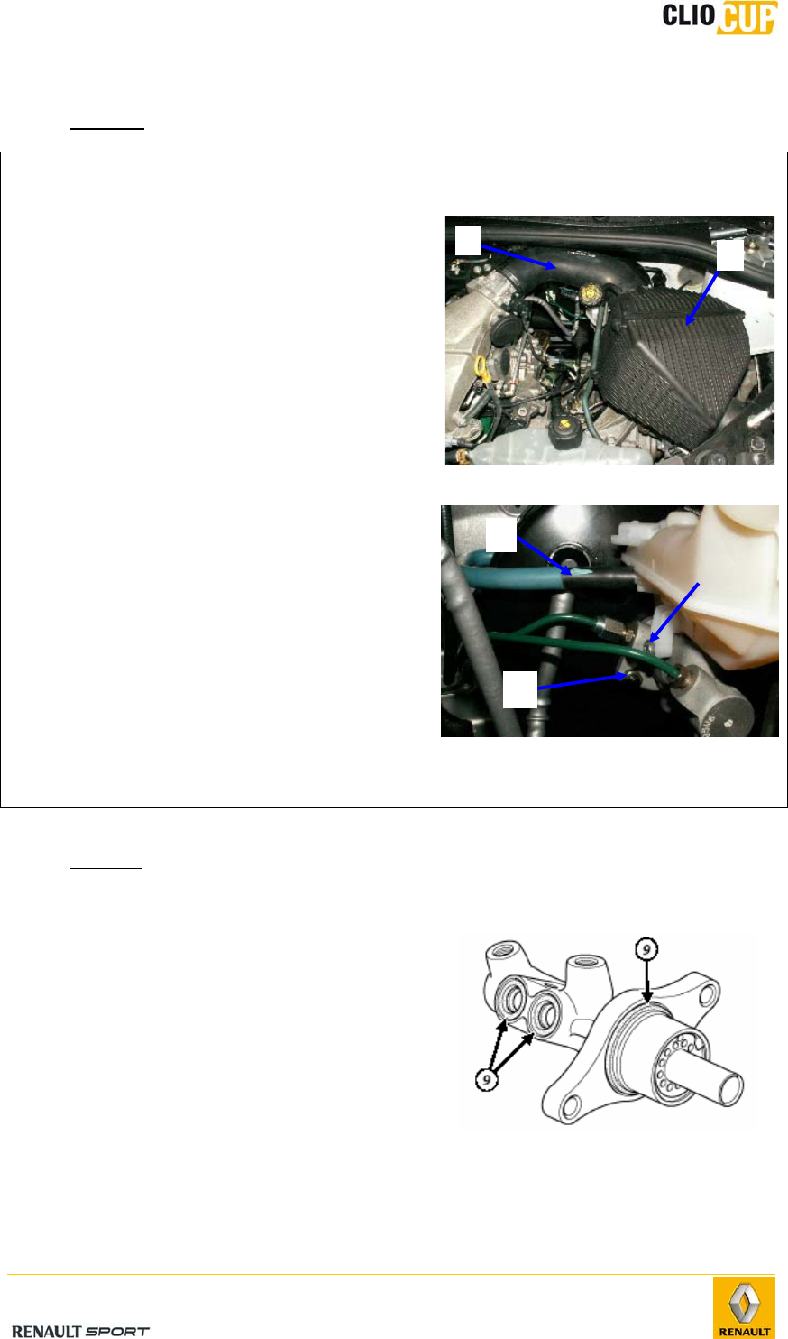
1 -
Remove the air box (1) and intake
pipe (2).
2 -
Drain the master cylinder tank with a
syringe.
3 -
Remove the clutch master cylinder
pipe (3).
4 -
Remove the brake pipes, taking care
to catch any brake fluid discharge.
5 -
Remove the 2 master cylinder
mounting bolts (4) on the amplifier.
6 -
Remove the master cylinder – tank
assembly.
7 -
Remove the master cylinder tank
mounting bolt (5).
8 -
Remove the master cylinder tank.
- Refitting
Perform the removal steps in reverse order.
The master cylinder seals (9) must be
replaced.
Ensure that the cup is centered on the braking
amplifier when refitting.
Tightening torques:
Master cylinder tank mounting
bolts: 8.5Nm.
Master cylinder mounting
nuts: 25Nm.
Brake pipes: 17Nm.
2
5
3
1
4
2010 Release
E-50
Braking amplifier
The brake booster cannot be repaired. Maintenance operations are only allowed on the
following parts:
Air filter
Check valve
- Removal
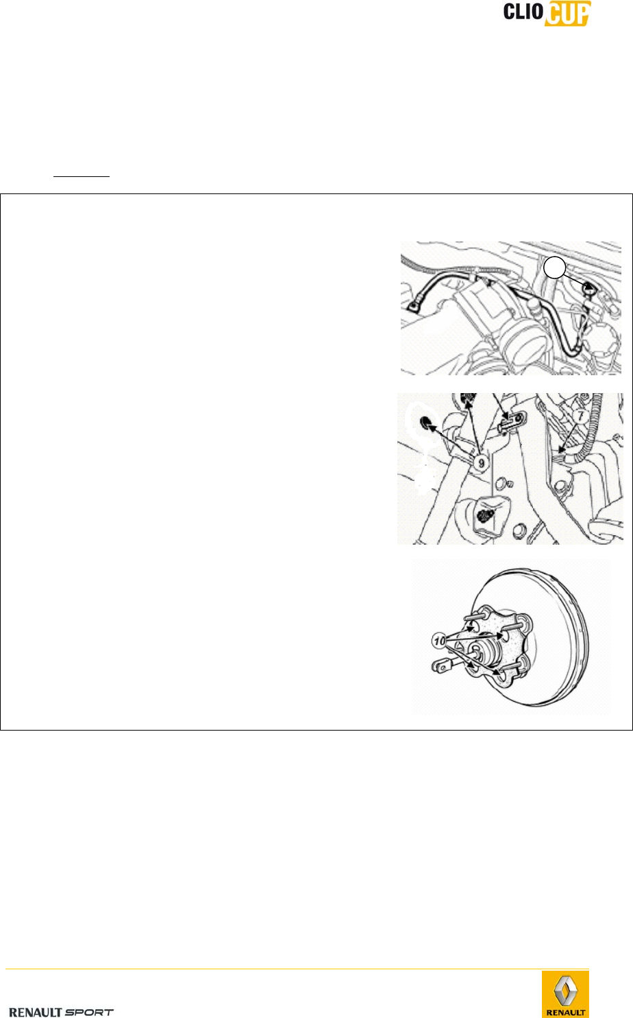
Operations Photos
1 -
Remove the air box and intake pipe.
2 -
Remove the check valve at the amplifier lever
(1).
3 -
Remove the master cylinder (see previous
paragraph).
4 -
Remove the dual safety coupling shaft (5)
between the braking amplifier thrust rod and the
brake pedal.
5 -
Remove the braking amplifier mounting nuts (9)
6 -
Remove the braking amplifier.
7 -
Remove the braking amplifier spacer mounting
bolts (10).
8 -
Remove the braking amplifier spacer.
1
2010 Release
E-51
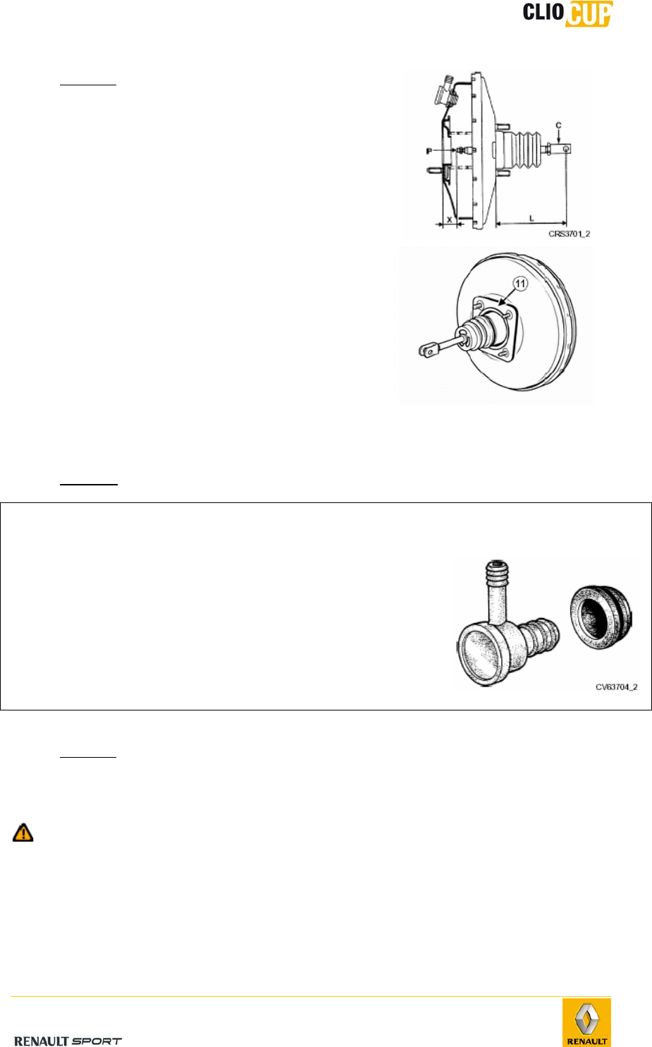
- Refitting
Perform the removal steps in reverse order.
Tighten the amplifier and spacer bolts to
21Nm.
Check the dimension L = 171mm, adjustable
using the rod (C).
Drain the braking circuit.
Ensure that the braking amplifier gasket seal
(11) is present and replace it if faulty.
On each removal, systematically replace the
coupling shaft (ref 82 00 420 641) between
the braking amplifier thrust rod and the brake
pedal.
Ensure it is locked.
Check valve
- Removal
Operation Photo
1 -
Disconnect the check valve from the brake booster.
2 -
Pull and rotate the valve to release it from the rubber
sealing washer.
- Refitting
Perform the removal steps in reverse order.
Check the condition of the sealing washer and check valve and replace them if necessary.
Take care not to push the sealing washer into the braking amplifier when inserting
the valve.
2010 Release
E-52
Wastegate
- Operation
The wastegatecan be adjusted by the driver from his seat:
Tighten the star wheel to increase rear braking,
Loosen the star wheel to reduce rear braking.
Above a pressure of 10 bars in the braking circuit, and depending on the setting, the rear
circuit pressure is limited to between 10 and 40 bars.
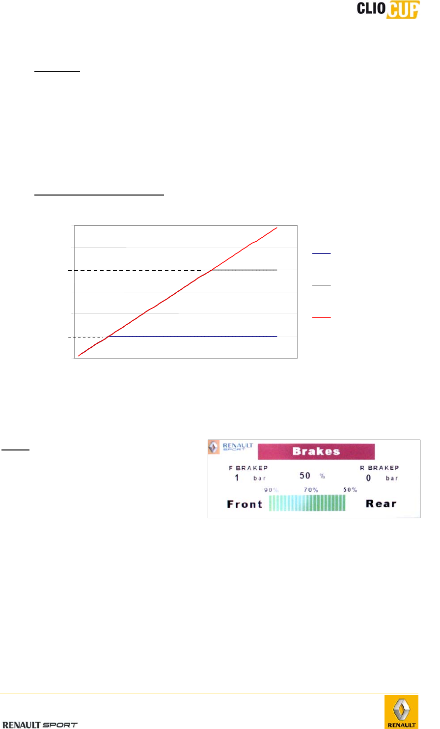
- Wastegate operating curve:
Note: The front/rear pressure
distribution can be
displayed on the "Brakes"
page of the display (if the
optional data acquisition
kit 77 11 160 189 has
been fitted onto the
vehicle).
-
0
10
20
30
40
50
60
Force applied to pedal
Pressure
(bar)
Rear pressure
fully open
Rear pressure
fully closed
Front pressure
2010 Release
E-53
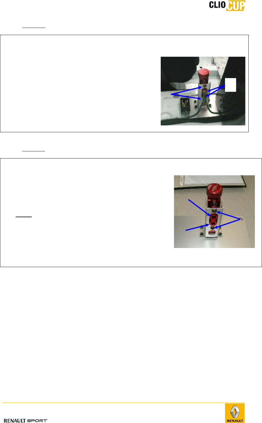
Removal
Operations Photos
1 - Unscrew the connectors (1) (allow for brake fluid
discharge).
2 - Remove the mounting bolts (2) and the wastegate.
- Refitting
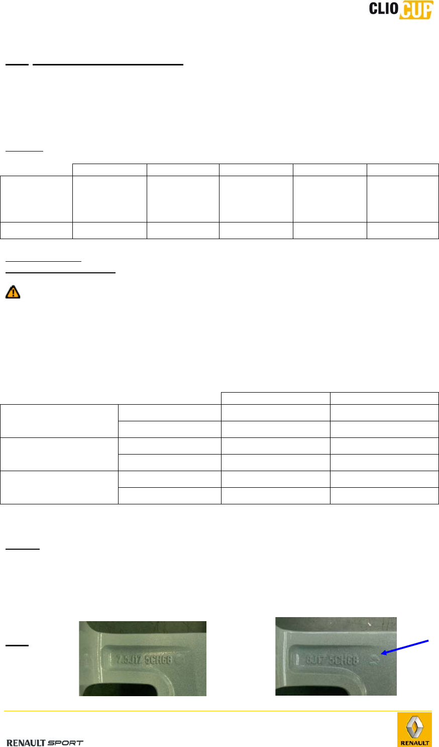
Operations Photos
1 -
Fit the wastegate on the support using the two bolts
(2).
2 -
Place the connector ends in the wastegate’s threaded
holes. Initiate threading manually.
Note: Follow the direction of assembly.
3 -
Tighten the connectors to 13Nm.
4 -
Drain the braking circuit.
5 -
Preset the wastegate to the centre position: 15 “clicks"
from one of the 2 end positions.
1
2
2
Input
Output
2010 Release
E-54
4.6 WHEELS AND TYRES
4.6.1 CHARACTERISTICS
Wheels
Material: Aluminum/magnesium alloy.
A B C D E
Wheel type Width
(inches)
Wheel rim
profile
Nominal
under tyre
bead
(inches)
Number of
holes ET offset
8J×17 8 J 17 5 68
Maximum offset: 0.3mm measured on the wheel rim.
Maximum out-of-round: 0.3mm measured on the tyre bead bearing surface.
When balancing the fitted wheels, it is essential to avoid placing the balancing
weights in an area where they could come into contact with the EE’ support in
steering lock position.
Tyres
The tyres are made by Michelin.
Dry Wet
Front S9C P2E
Type Rear S9C P2E
Front 20/61-17 20/61-17
Dimensions Rear 20/61-17 20/61-17
Front 1.6* 1.7*
Cold inflation
pressure (bar) Rear 1.7* 1.8*
*The cold pressure values are given for information and should be adjusted according to
track conditions (temperature, roughness, grip, amount of water, etc.).
Notes:
To ensure predictable and reproducible pressure increase, we strongly
recommend the use of a water vapor-free inflation gas (dry air, nitrogen, etc.).
To ensure a good valve seal, the cap should always be used.
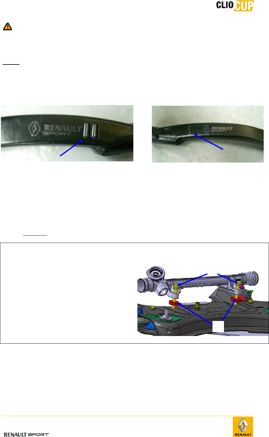
The wheels are identified by the two engravings on the inside, corresponding to
their widths (see photos). Only the engraving with a cross (1) on the right
should be taken into account.
4.7 1

2010 Release
E-55
KIT EVO 2009
4.7.1 NOMENCLATURE
WISHBONES
Designation Reference Qty
Assembled wishbone with A and B casings 77 11 162 592 2
External snap ring Ø58 77 11 162 563 2
Point A spacer 77 11 162 525 4
Point B spacer 77 11 162 526 4
Ball joint Ø15 77 11 128 370 4
Internal snap ring Ø30 77 11 128 850 4
M12 deported locknut 77 03 034 248 4
M12 washer 77 11 156 931 4
CHC screw M12 x 145 77 11 162 527 2
CHC screw M12 x 86 77 11 156 908 2
BODYWORK
Black rear diffuser 77 11 162 532 1
Diffuser’s duct 77 11 162 533 2
External exhaust nozzle 77 11 162 534 2
Front bumper skin 77 11 162 535 1
Front bumper inferior plastic fence 77 11 162 536 1
Inferior deflector 77 11 162 537 1
Left aerodynamic blade 77 11 162 538 1
Right aerodynamic blade 77 11 162 539 1
Anti-fog light left cover 77 11 162 540 1
Anti-fog light right cover 77 11 162 541 1
Front left bumper support 77 11 162 542 1
Front right bumper support 77 11 162 543 1
Left halogen headlight 77 11 162 544 1
Right halogen headlight 77 11 162 545 1
Black superior bumper trim cover 77 11 162 546 1
Black inferior bumper trim cover (F1 blade) 77 11 162 547 1
Black left rearview mirror shell 77 11 162 548 1
Black right rearview mirror shell 77 11 162 549 1
Left external rearview mirror 77 11 162 550 1
Right external rearview mirror 77 11 162 551 1
Assembled Renault ensign 77 11 162 565 1
FASTENERS
Diffuser screw 77 03 017 090 2
Diffuser nut 77 03 034 276 2
Screw for diffuser’s duct 77 03 008 211 6
Nut for diffuser’s duct 77 03 046 151 6
F1 blade fitting screw 77 03 017 101 8
Screw for bumper fitting on inferior radiator support 77 03 602 206 2
Screw for bumper fitting on front quarter panel 77 03 019 211 2
Retainer for bumper fitting on superior radiator support
77 03 072 360 2
Bumper retainer 82 00 700 969 2
Star rivet 77 03 072 419 18
Plastic clip for headlight fitting on front quarter panel 77 03 081 222 2
Black star rivet for superior bumper trim cover 77 03 072 322 4
Plastic clip for superior bumper trim cover 77 03 072 361 2
2010 Release
E-56
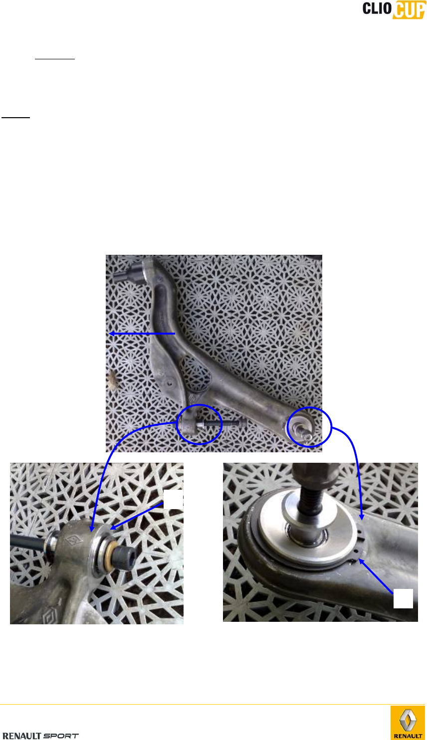
4.7.2 NEW WISHBONE MOUNTING
The wishbones can only be purchased with their A and B casings already fitted. You only
have to mount the ball joints 77 11 128 370 :
Fit the snap ring 77 11 162 563 in its groove (B casing)
Heat the casing (oven) et cool the ball joint (freezer)
Do not heat the complete wishbone more than 100°C not to damage the point
E ball joint.
Fit the ball joint using a pressing machine leaning on the external ring of the
ball joint, without glue (If you do not have a press, a vice should be sufficient)
Fit the snap ring 77 11 128 850
Repeat this procedure for the 3 other ball joints
! WARNING ! Without either heating the casing or cooling the ball joint, you could
damage the parts because of too important force. Be careful to not deform the inner
shoulder of the B casing.
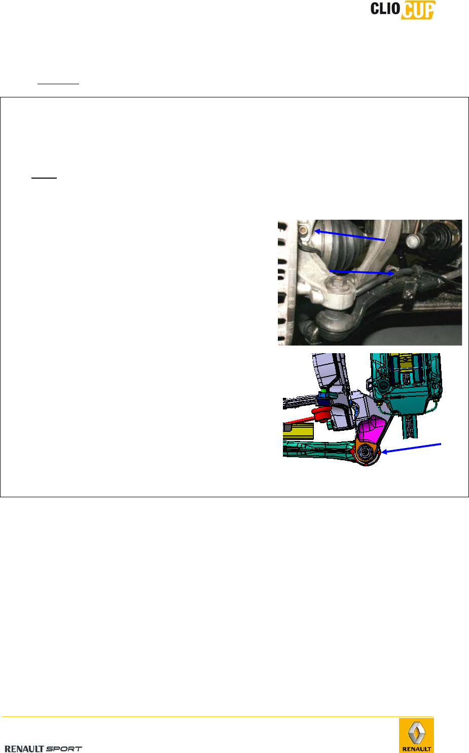
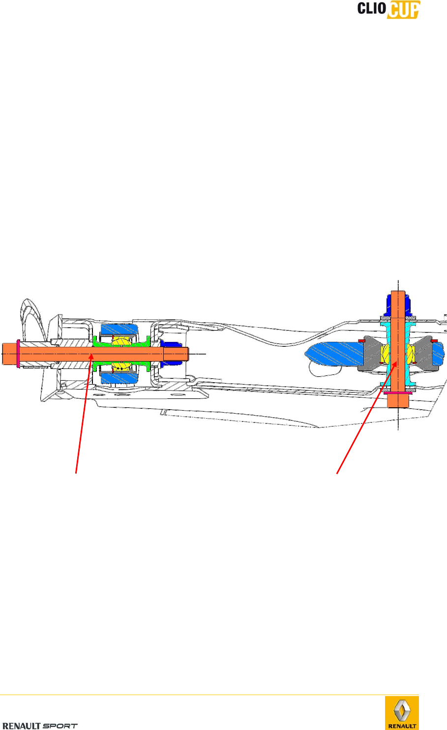
To ease the understanding of the fitting on the car, hereafter is a cut view of a left
wishbone mounted on the subframe :
Point A bolt:
Screw : 77 11 162 527
Under head washer : 77 11 156 931
Locknut : 77 03 034 115
Tightening torque : 80 N.m
Point B bolt :
Screw : 77 11 156 908
Under head washer : 77 11 156 931
Locknut : 77 03 034 115
Tightening torque : 80 N.m
2010 Release
E-57
4.7.3 EXTERNAL MIRRORS
The external mirrors directly take place instead of the old ones:
- Use the fasteners of the old ones (2 x 3 screws).
- Fit the shell, mirror pulled down.
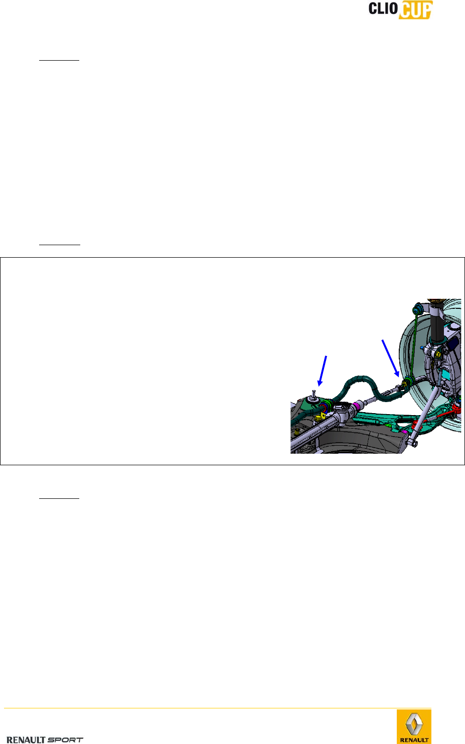
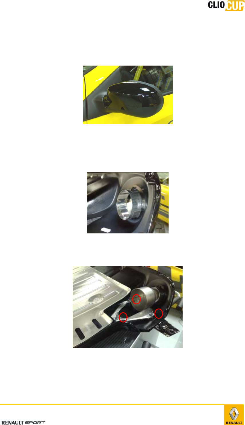
4.7.4 DIFFUSER
- Fit the external nozzles 77 11 162 534 on the diffuser :
- Fit the ducts 77 11 162 533 using the 6 screws 77 03 008 211 and the 6 nuts 77
03 046 151 :
(Recommended glue : Loctite® 222 low strength threadlock)
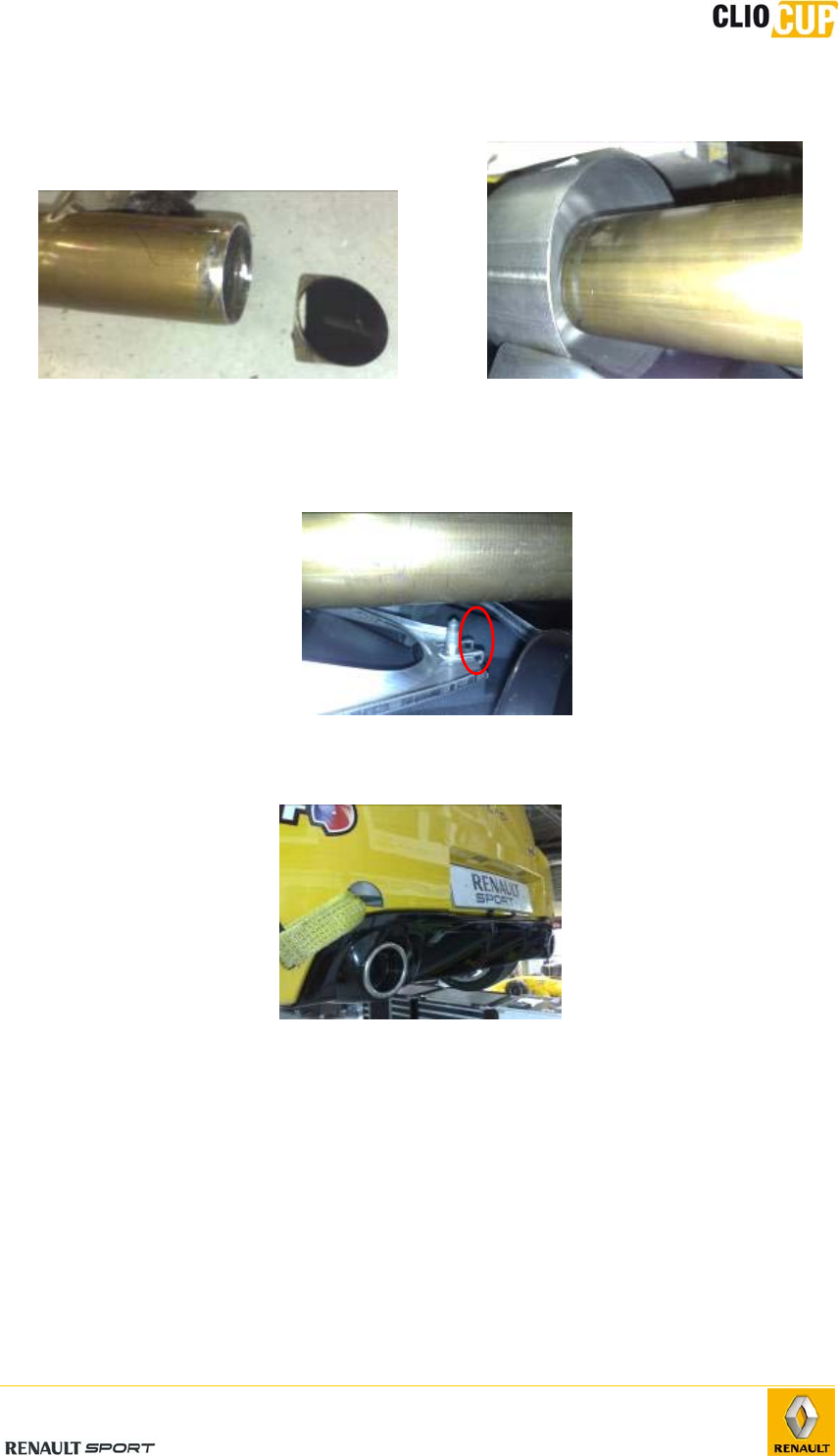
2010 Release
E-58
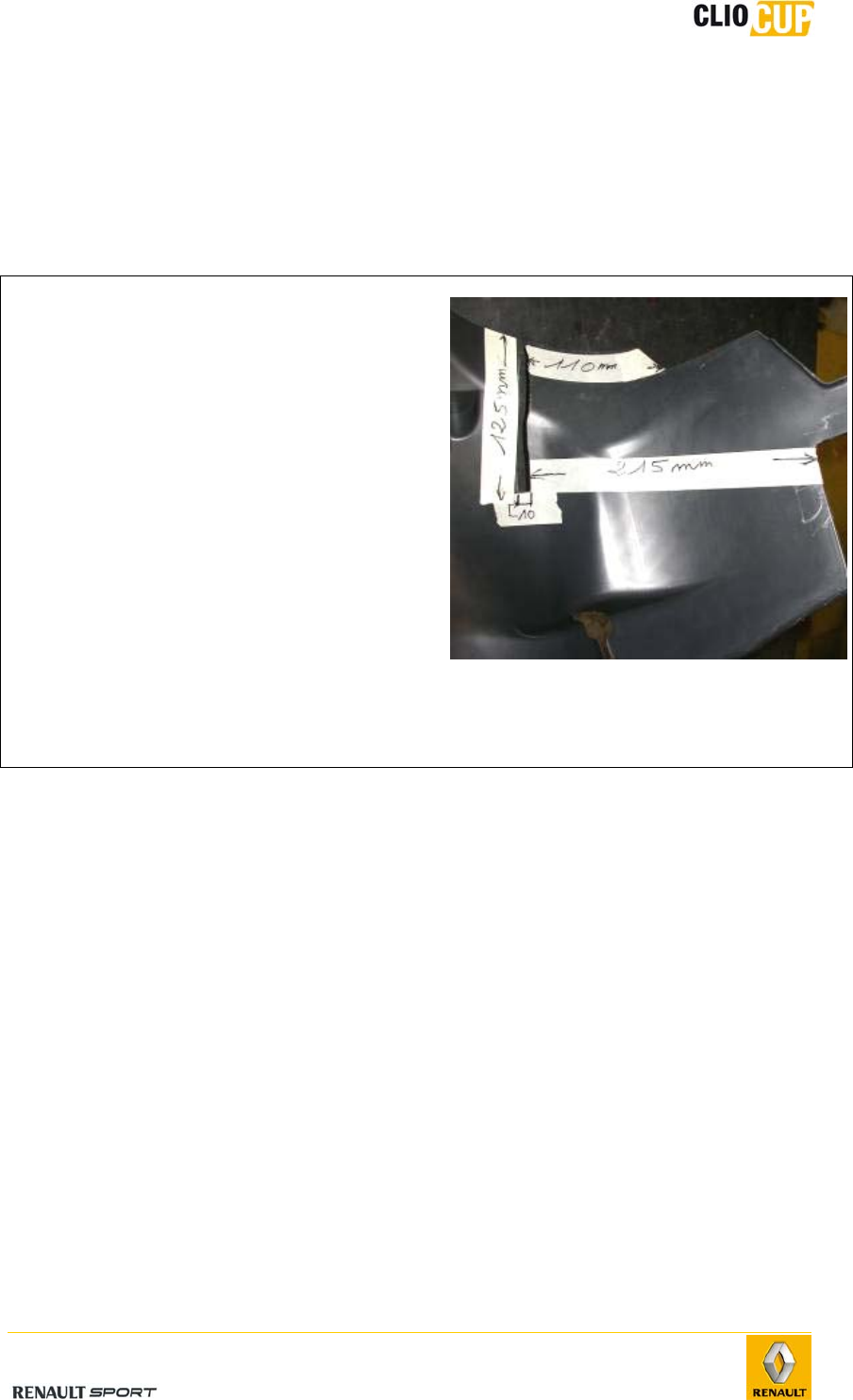
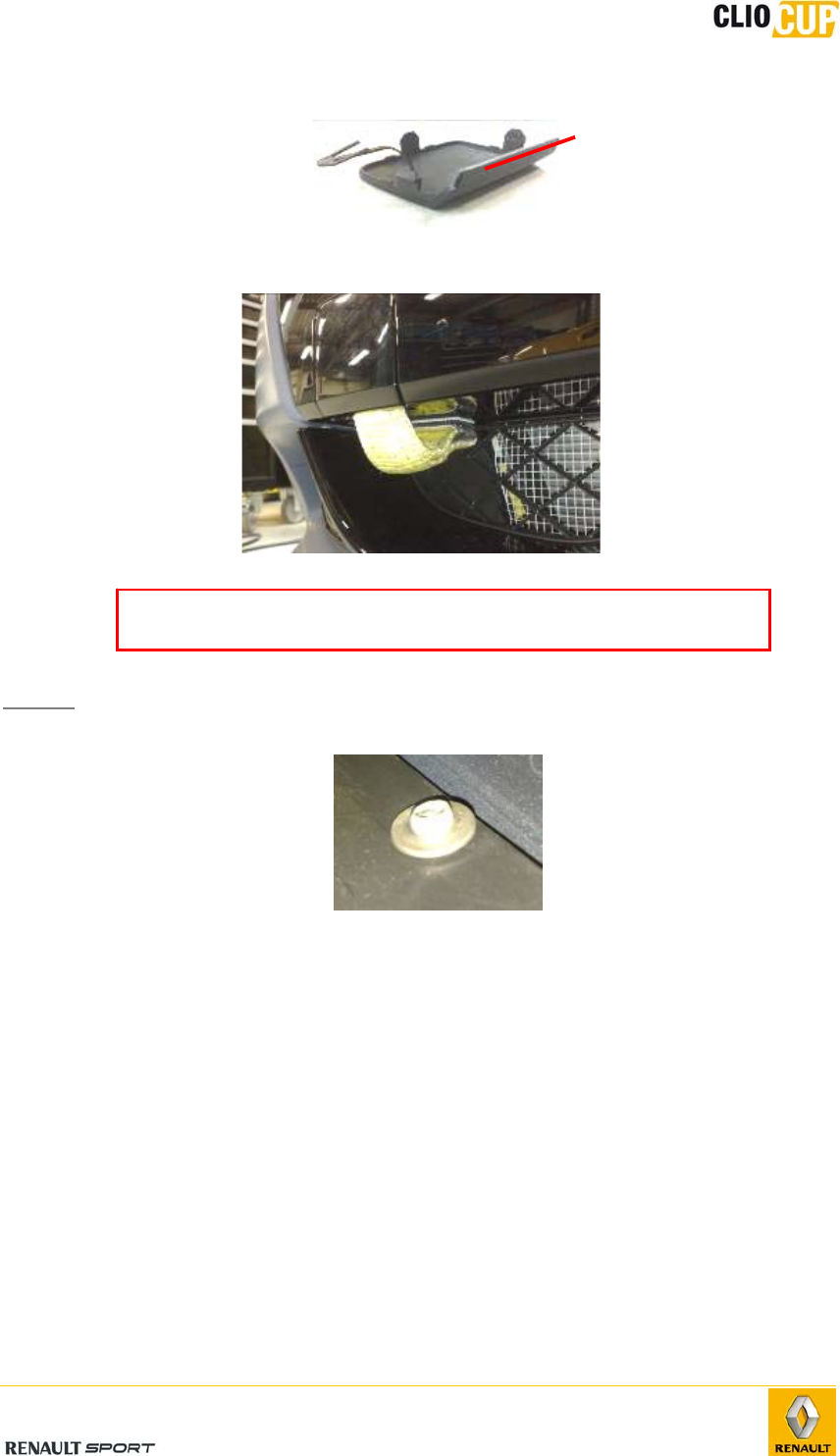
- Cut right the exit of the silencer tubes starting from the bottom of the genuine
bevel :
Recovering distance in the duct
between 20 and 30 mm
- It is allowed to cut the screws in front of the duct to prevent from a possible
contact with the silencer tubes :
- Fit the diffuser on the car. Fasteners are the same as the ones used for the old
one (new fasteners included) :
4.7.5 FRONT HEADLIGHTS
The front headlights directly take place instead of the old ones.
- Change the plastic nut 77 03 081 222 on each side :
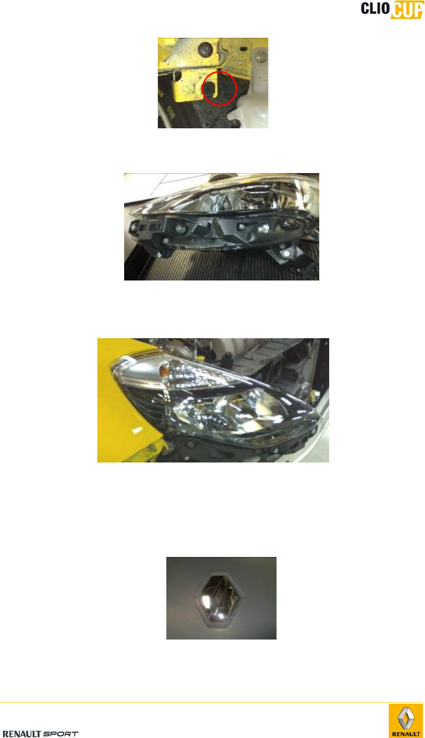
2010 Release
E-59
- Fit the bumper supports on the headlights using 4 rivets 77 03 072 419 (2 per
headlight):
- Use the fasteners of the old ones (2 x 3 screws).
- Connect the headlight to the front wiring loom.
! The connector of the left headlight is reversed compared to the old one!
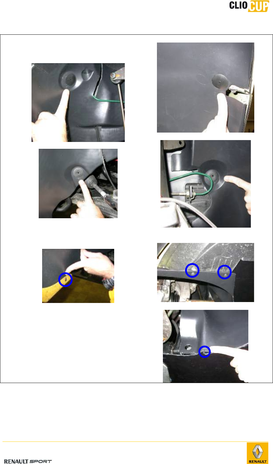
4.7.6 FRONT BUMPER
- Get back the 3 fences of the old bumper.
- Fit the towing hook.
- Fit the Renault ensign using the 2 screws of the old ensign :
- Fit the plastic central fence 77 11 162 536 on the bumper.
- Fit the superior bumper trim cover on the bumper.
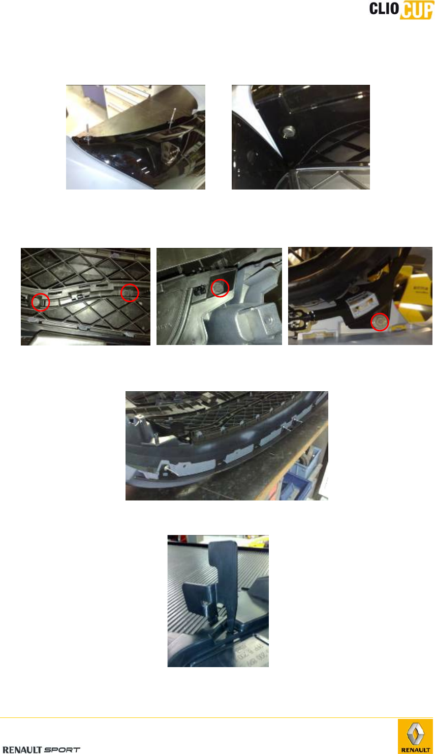
2010 Release
E-60
- Fasten definitively the superior trim cover 77 11 162 546 using the 4 rivets 77
03 072 322 and the 2 plastic clips 77 03 072 361 :
Rivets on superior face Plastic clip on inferior face
- Fit the inferior bumper trim cover 77 11 162 547 on the plastic central fence.
- Fasten the inferior trim cover using the 8 screws 77 03 017 101 :
- Fit the new aerodynamic blade (in 2 parts) on the bumper and fasten it definitely
using 4 rivets 77 03 072 419 :
- Bend the 2 brackets of the inferior deflector:
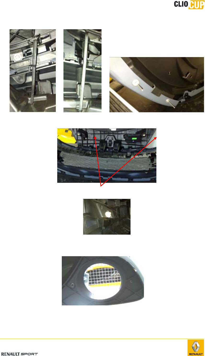
2010 Release
E-61
- Fit the deflector using the 10 rivets 77 03 072 419 :
- Fit the old central fence using plastic collars:
- Fit the 2 plastic retainers 82 00 700 969 on the front bumper:
- Fit the 2 old anti-fog light fences (glue, plastic collars or star rivets) on the anti-
fog light covers :
- Fit these covers on the bumper.
- Fit the bumper on the car. Fasteners are the same as the ones used for the old
one.
2010 Release
E-62
- Cut the inferior part of the towing hook plastic trap door:
- Fit the strap on the bumper using a velcro type fastener :
It is forbidden to paint all parts in genuine shiny black paint.
The anti-fog light and central fences are mandatory.
NOTA : It is possible to use a standard rivet with a dished washer, in case you would not
have any star rivet:

2010 Release
E-63
4.8 TIGHTENING TORQUES
Parts Tightening
torques in Nm Specific
recommendations
FRONT AXLE
Wheels
Wheel studs 100 Copper grease
Wheel nuts 110
Wheel speed sensor 8 to 10
Drivetrain nut 280
Damper system
Upper shock absorber nut 100
Point F plate bolt on body 100
Support strut mounting bolt on pivot
holder
105
Pivot holder
Point E nut 105 Bolt class: 12.9
EE’ support
Mounting bolt on pivot holder 140
Ball joint E’ mounting bolt 26.5
Wishbone
Point A bolt 80
Point B bolt 80
Subframe
Aluminum plate mounting bolt on
subframe 100
Connecting torque rod mounting bolt on
GB yoke 105
Connecting torque rod mounting bolt on
subframe 105
Bolts for points P and P’ 120
QQ’ tie-rod mounting bolts to body 105
QQ’ tie-rod mounting bolts to subframe 80

Anti-roll bar tie-rod mounting bolts 44
Point H nut 37
Anti-rotation tie-rod mounting bolt on
wishbone 100
Anti-roll bar
Bearing mounting bolts on subframe 21
Anti-roll bar tie-rod nut 44
REAR AXLE
Wheel
Wheel bolt 110
Hub
Spindle nut 220
Damper system
Upper mounting bolt 80
Lower mounting bolt 105
Rear axle
Bearing mounting bolt on body 62
Nut for bearing mounting bolt on rear axle 125
Plate spindle on axle 71
Brake hose nut 14
STEERING
Axial ball joint
Axial ball joint 50
Point H ball joint nut 37
Wheel alignment locknut 53
Steering unit
Steering unit mounting on subframe 105
Folding yoke cam bolt 24
Steering column
Column mounting bolt on roll cage
crossmember 105
Sheath bolt 21
Sheath mounting bolt on roll cage stays 21
Intermediate shaft mounting bolt on column 34
Wheel hub bolt 44

2010 Release
E-65
Electric power steering
Module mounting bolt on steering column 6
BRAKING SYSTEM
Front brake caliper
Brake caliper mounting bolt on pivot 164
Brake hose banjo bolt 14
Bleed screw 5 to 8
Front disc
Disc bolt 21
Rear brake caliper
Brake caliper mounting bolt on axle 105
Brake hose nut 14
Rear disc
Spindle nut 220
Master cylinder
Mounting bolt on brake booster 23
M10 x 100 master cylinder outlets 13
Braking amplifier
Mounting bolt on bulkhead 21
Spacer mounting bolt 21
Rear brake limiter
Lines on brake limiter 13
2010 Release
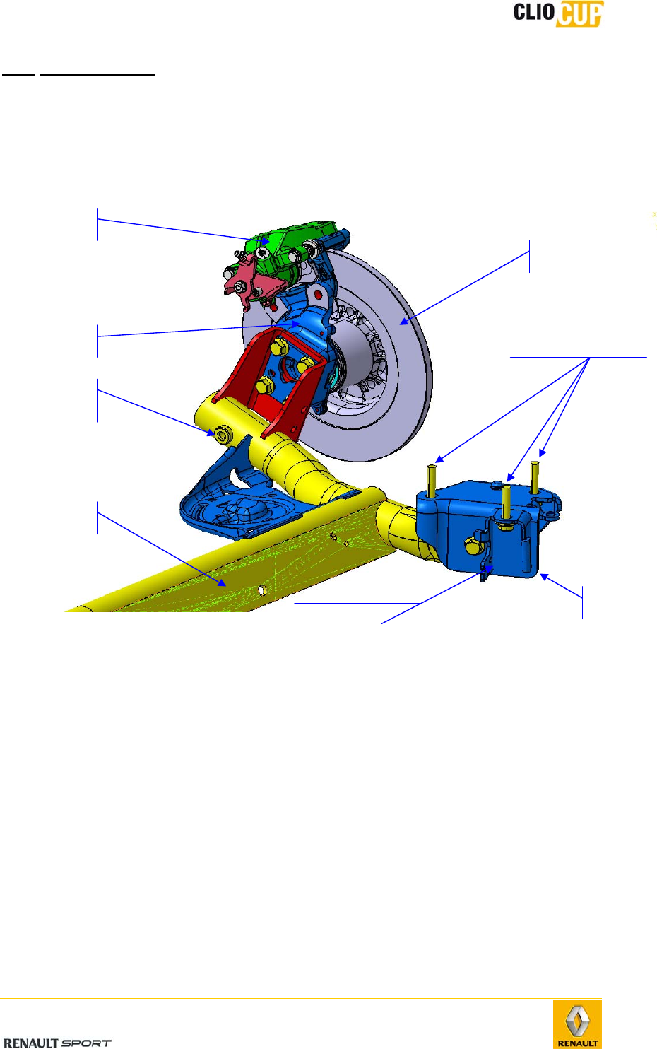
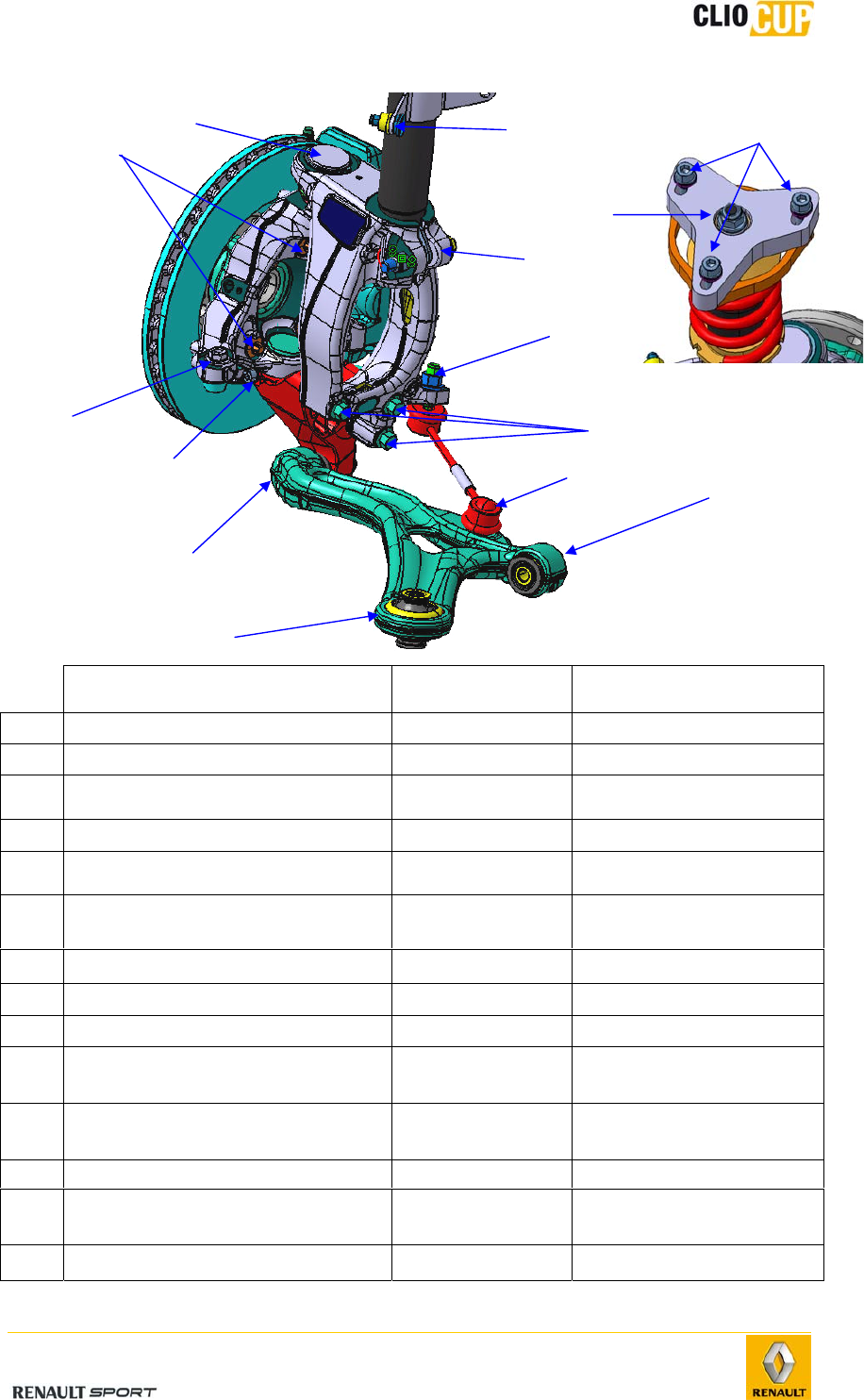
E-66
Parts Tightening
torque in Nm Specific
recommendations
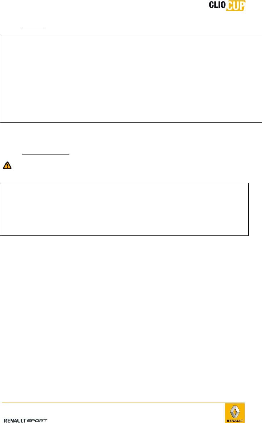
(1) Point A bolt 80
(2) Point B bolt 80
(3) EE’ support nut on wishbone
(point E) 105 Bolt class: 12.9
(4) EE’ support bolt on pivot holder 105
(5) EE’ support bolts on pivot (point
E’) 26.5
(6) Pivot ball joint nut on pivot
holder (point F’) 140
(7) Support strut bolt on pivot holder 105
(8) Point F plate bolt on body 100
(9) Upper shock absorber nut 105
(10) Anti-rotation tie-rod mounting
bolt on pivot holder 100
(11) Anti-rotation tie-rod mounting
bolt on wishbone 100
(12) Point H ball joint nut 37
(13) Anti-roll bar tie-rod mounting bolt
on support strut 44
(14) Wheel bearing mounting bolt 105
1
4
2
3
6
5
7
12
11
10
13
14 8
9
2010 Release
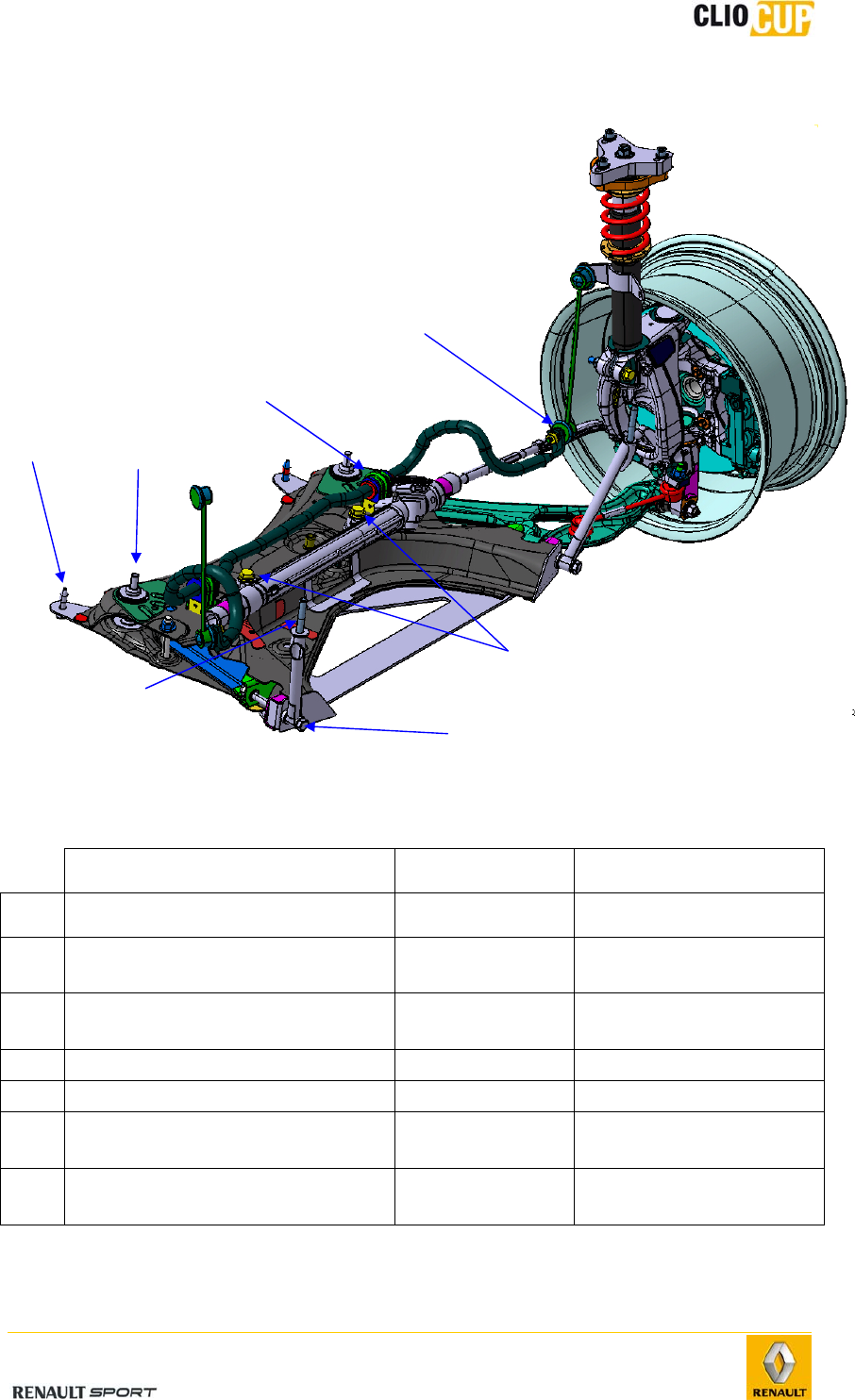
E-67
Parts Tightening
torque in Nm Specific
recommendations
(14) Anti-roll bar mounting bolt on tie-
rod 44
(15) Anti-roll bar bearing bolts on
subframe 21
(16) Steering unit mounting bolt on
subframe 24
(17) QQ’ tie-rod bolt on subframe 80
(18) QQ’ tie-rod bolt on body 105
(19) Reinforcement plate mounting bolt
on body (point P’) 120
(20) Rear subframe mounting bolt on
body (point P) 120
17
16
15
14
19
18
20
2010 Release
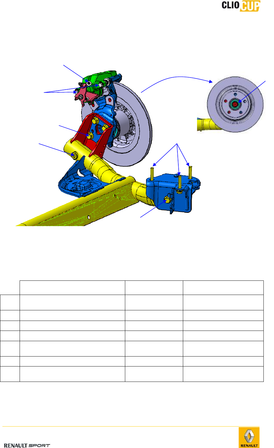
E-68
Parts Tightening
torque in Nm Specific
recommendations
(1) Spindle nut 220
(2) Hub carrier bolt on axle 71
(3) Small column bolt 32
(4) Bearing mounting bolt on body 62
(5) Lower shock absorber mounting
bolt 105
(6) Brake hose nut 14
(7) Nut for bearing mounting bolt on
rear axle 125
5
2
1
3
4
6
7
2010 Release
E-69
Parts Tightening
torque in Nm Specific
recommendations
(1) Folding yoke cam bolt 24
(2) Column mounting bolt on roll cage
crossmember 105
(3) Sheath bolt 21
(4) Sheath mounting bolt on roll cage
stays 21
(5) Intermediate shaft mounting bolt
on column 34
1
2
5
3
4
