Renesas Electronics America G1D Bluetooth Low Energy Module User Manual
Renesas Electronics America, Inc Bluetooth Low Energy Module Users Manual
Users Manual
APPLICATION NOTE
R01AN2919EU0100_RL78G1D Rev. 1.00 Page 1 of 4
Sept. 15, 2015
RL78/G1D
RL78/G1D Solution Kit – PMOD Module Hardware Manual
Introduction
This document represents RL78/G1D Solution Kit’s PMOD module. The document describes hardware platform
information such as PMOD™ peripheral connection, RL78/G1D-SK Bluetooth
®
module interface and its Bluetooth
®
connectivity, bill of materials, and schematics.
Target Device
RL78/G1D, G13 Group (R5F11AGJ)
This Solution Kit’s PMOD module includes Renesas’ Intelligent Bluetooth
®
Smart device with part number starting
with R5F11A (256 KB program flash memory, 20 KB RAM and 8 KB data flash memory).
R01AN2919EU0100_RL78G1D
Rev. 1.00
Sept. 15, 2015

RL78/G1D RL78/G1D Solution Kit – PMOD Module Hardware Manual
R01AN2919EU0100_RL78G1D Rev. 1.00 Page 2 of 4
Sept. 15, 2015
Contents
1. Overview ......................................................................................................................... 3
1.1
Specification Outline .................................................................................................................. 3
2. RL78/G1D-SK PMOD module interface ......................................................................... 4
3. RL78/G1D-SK Bluetooth module Pin Configuration .................................................... 5
4. RL78/G1D-SK PMOD Module Design Bill of Material ................................................... 6
5. Circuit Diagrams ............................................................................................................. 7
Appendix A - References ...................................................................................................... 8
Appendix B - Conformity Assessment ................................................................................. 9
RL78/G1D RL78/G1D Solution Kit – PMOD Module Hardware Manual
R01AN2919EU0100_RL78G1D Rev. 1.00 Page 3 of 4
Sept. 15, 2015
1. Overview
RL78/G1D-SK PMOD module has two sections: Bluetooth
®
module (RL78/G1D-SK) and PMOD™ connector
(PMOD) with power consumption measurement.
This module allows you to measure current consumption for RF section and microcontroller (MCU) section using R1
and R4 respectively. To measure current, remove the resistor and attach current probe to the resistor pads. Read the
current value from the meter.
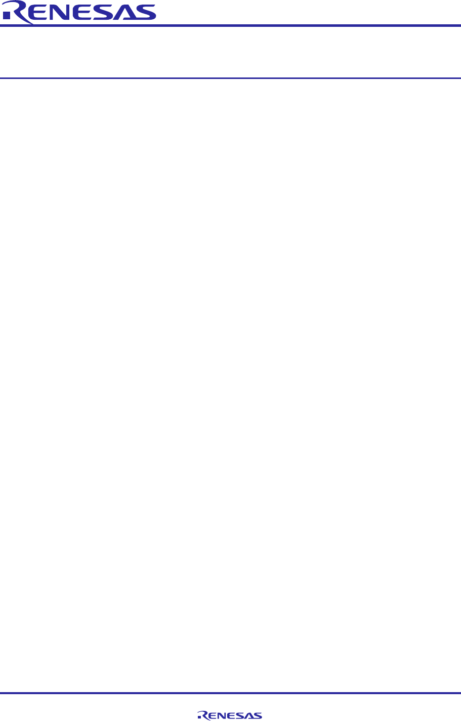
The PMOD and RL78/G1D-SK sections are divided by breakaway groove at bottom side. Figure 1 shows top and
bottom view of the module including breakaway groove marking. After breaking the board, you get small Bluetooth
®
Smart module (RL78/G1D-SK) which has 30 solder pads at bottom side for power supply, debug/program interface,
and I/O interface. Once broken into two pieces, the PMOD™ section is of no use.
Bottom ViewTop View
Break away
Groove
Dimension
Figure 1 RL78/G1D-SK PMOD module
1.1 Specification Outline
The specification of RL78/G1D-SK PMOD module is described as below Table 1.
Table 1 RL78/G1D-SK PMOD module Specification
Item Content
Dimension
22.86 mm
x 15.24 mm ( 0.9 inch x 0.6 inch)
Operation Power Supply Voltage 3.0 V
Maximum Power Supply Voltage 3.6 V
Average Operation Current 10 µA
Note1
Maximum Total Output Current 150 mA
Note2
Operating Ambient
Temperature/Humidity
0
°
C to +60
°
C, 10% to 80% RH (non condensing)
Storage Temperature
−
15
°
C to +60
°
C, 10% to 80% RH (non condensing)
Note 1: One-second interval with keeping Bluetooth
®
connection
Note 2: Refer Electrical Specifications of RL78/G1D User’s Manual: Hardware, R01UH0515EJ0100 [1]
RL78/G1D RL78/G1D Solution Kit – PMOD Module Hardware Manual
R01AN2919EU0100_RL78G1D Rev. 1.00 Page 4 of 4
Sept. 15, 2015
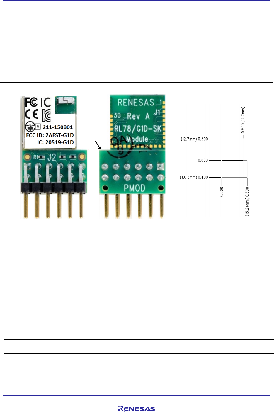
2. RL78/G1D-SK PMOD module interface
For interface connection, the RL78/G1D-SK PMOD module has 2x6 pin, standard 0.1-inch pitch right angle male
connector. Using this connector, you can program or debug RL78/G1D-SK Bluetooth
®
module. If you program
firmware in Modem configuration, the module can be used for Bluetooth
®
communication
by plugging into one of the
PMOD connectors on the Renesas RDK board like YRDKRL78-G14. The PMOD connector pin number and pin
orientation are shown in Figure 2, and Table 2 shows the pin configuration.
Figure 2 PMOD connector pin assignment for RL78/G1D-SK PMOD module
Table 2 Interface between Host and Peripheral PMOD
PMOD Pin
Number
Solution Kit
(Host)
RL78/G1D
-
SK PMOD
(Peripheral) PMOD Signal
1 PMOD-WAKEUP P30 PMOD_CS
2 PMOD-TxD P11 (RxD0/SI00) PMOD_MOSI
3 PMOD-RxD P12 (TxD0/SO00) PMOD_MISO
4 PMOD-SCK P10 (SCK00) PMOD-SCK
5 GND GND GND
6 VDD (3.3 V) VDD (via R1 and R4) VDD
7 PMOD-SDIR (INTP) P21 PMOD_PIN7
8 PMOD-GPIO nRESET PMOD_PIN8
9 PMOD-GPIO P16 PMOD_PIN9
10 PMOD-GPIO TOOL0 PMOD_PIN10
11 GND GND GND
12 VDD (3.3 V) VDD (via R1 and R4) VDD
The PMOD connector has flexible interface to communicate either UART or CSI mode. The RL78/G1D-SK PMOD
module can support five communication modes based on programmed firmware as below. Refer document
R01UW0095EJ0117 [2] for detail.
2-Wire UART
3-Wire UART
2-Wire UART with branch
4-Wire CSI
5-Wire CSI
RL78/G1D RL78/G1D Solution Kit – PMOD Module Hardware Manual
R01AN2919EU0100_RL78G1D Rev. 1.00 Page 5 of 4
Sept. 15, 2015
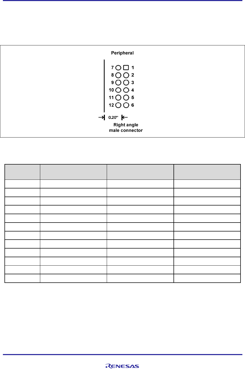
3. RL78/G1D-SK Bluetooth module Pin Configuration
After breaking away the PMOD connector of the PMOD module, you get Bluetooth
®
module, with dimensions
12.7x12.7 mm (½ inch square). The module has 30 gold plated pads at bottom layer and their respective functions are
described in Table 3 . Refer MCU device detail in RL78/G1D User’s Manual: Hardware, R01UH0515EJ0100 [1].
P147
P23
P22
P21
P20
P03
P02
P01
P00
VDD_IO
nRESET
TOOL0
GND
GND
VDD_RF
P30
P16
P15
P14
P13
P12
P11
P10
GPIO0
GPIO1
P61
P60
P137
P121
P120
BOTTOM VIEW
Figure 3 RL78/G1D-SK module pin configuration
Table 3 RL78/G1D-SK module Pin Function
Pin Number Designator
Description Remark
1 GND Ground
2 VDD_RF RF +3.0 volt power supply
3 P30 GPIO/External Interrupt Input 3 / Real-time clock (1 Hz) Output
4 P16 GPIO/ Timer01 Input, Output / External Interrupt Input 5
5 P15 GPIO/ CSI20 clock/ I
2
C 20 clock Output/ Timer02 Input, Output I
2
C 20: Simplified I
2
C
6 P14 GPIO/ CSI20 Input/ I
2
C 20 Data/IIC0A clock Output/ Timer03 Input, Output I
2
C 20: Simplified I
2
C
7 P13 GPIO/ CSI20 Output/ I
2
C 0A Data/ Timer04 Input, Output
8 P12 GPIO/ CSI00 Output / UART 0 Transmit Output / Timer05 Input, Output
9 P11 GPIO/ CSI00 Input/ UART 0 Receive Input/ I
2
C00 Data/ Timer06 Input,
Output
10 P10 GPIO/ CSI00 clock / I
2
C00 clock Output / Timer07 Input, Output
11 P147 GPIO/ Analog Input 18
12 P23 GPIO/ Analog Input 3
13 P22 GPIO/ Analog Input 2
14 P21 GPIO/ Analog Input 1/ Analog Reference Minus
15 P20 GPIO/ Analog Input 0/ Analog Reference Plus
16 P03 GPIO/ Analog Input 16/ UART 1 Receive Input
17 P02 GPIO/ Analog Input 17/ UART 1 Transmit Output
18 P01 GPIO/ Timer00 Input
19 P00 GPIO/ Timer00 Output
20 VDD_IO MCU +3.0 volt power supply
21 nRESET Reset Input
22 TOOL0 General purpose Input/ Debug, Programming
23 GND Ground
24 P120 GPIO/ Analog Input 19
25 P121 General purpose Input Input only
26 P137 GPIO/ External Interrupt Input 0
27 P60 GPIO/ I
2
C 0A clock Output
28 P61 GPIO/ I
2
C 0A Data
29 PGPIO1 RF transmission output for external power amplifier control Active High
30 PGPIO0 RF transmission output for external power amplifier control Active Low
Note: General Purpose Input Output (GPIO)

RL78/G1D RL78/G1D Solution Kit – PMOD Module Hardware Manual
R01AN2919EU0100_RL78G1D Rev. 1.00 Page 6 of 4
Sept. 15, 2015
4. RL78/G1D-SK PMOD Module Design Bill of Material
Table 4 shows the bill of material for RL78/G1D-SK PMOD module.
Table 4 Bill of material for RL78/G1D-SK PMOD module
Item Qty Reference Part Footprint Description Manufacturer Mfg PN
1 3 C1,C2,C10 0.1uF 402 CAP CER 0.1UF 16V
10% X5R 0402
Murata GRM155R61A104KA01D
2 1 C3 0.47uF 402 CAP CER 0.47UF
6.3V 10% X5R 0402
Taiyo Yuden JMK105BJ474KV-F
3 1 C11 10uF 603 CAP CER 10UF 6.3V
20% X5R 0603
Murata GRM188R60J106ME47J
4 1 C9 2.2uF 402 CAP CER 2.2UF 6.3V
10% X6S 0402
Murata GRM155C80J225KE95D
5 2 C5,C6 8pF 402 CAP CER 8PF 50V
NP0 0402
Murata GRM1555C1H8R0DA01D
6 2 C7,C8 9pF 402 CAP CER 9PF 50V
NP0 0402
Murata GRM1555C1H9R0DA01D
7 0 C4 NLC 402 No load capacitor
8 1 E1 W3008 ANTENNA
BT/WLAN/WIFI CER
Pulse W3008
9 1 J2 CON12B CONN HEADER
.100" DUAL R/A
12POS
Sullins PRPC006DBAN-M71RC
10 1 L1 10uH 603 FIXED IND 10UH
50MA 900 MOHM
SMD
Murata LQM18FN100M00D
11 6 R1,R4,R5,
R6,R7,R10
0 402 RES 0.0 OHM 1/16W
0402 SMD
Stackpole RMCF0402ZT0R00
12 3 R2,R8,R9 10K 402 RES 10.0K OHM
1/16W 5% 0402 SMD
Yageo RC0402JR-0710KL
13 1 R3 1K 402 RES 1.00K OHM
1/16W 5% 0402 SMD
Stackpole RMCF0402JT1K00
14 1 R11 6.8 M 402 RES 6.8 M OHM
1/16W 5% 0402 SMD
Yageo RC0402JR-076M8L
15 1 SH1 SHIELD Shield, metal can Custom N/A
16 1 U1 R5F11AGJ QFN-48,
6x6 mm
CPU,BLE,256K,RL78
/G1D
Renesas R5F11AGJANA
17 1 Y1 32MHz 1.2x1.6 Crystal,32MHz
(8pF,20ppm,1.2x1.6)
Abracon ABM12-32.000MHZ-B2X-T3
18 1 Y2 32.768kHz 1.0x1.6 Crystal,32.768kHz
(9pf,20ppm,1.0x1.6)
Abracon ABS05-32.768KHZ-9-T

RL78/G1D RL78/G1D Solution Kit – PMOD Module Hardware Manual
R01AN2919EU0100_RL78G1D Rev. 1.00 Page 8 of 4
Sept. 15, 2015
Appendix A - References
[1] RL78/G1D User’s Manual: Hardware, R01UH0515EJ0100 Rev.1.00, April 24, 2015
[2] Bluetooth
®
Low Energy Protocol Stack User’s Manual, R01UW0095EJ0117 Rev.1.17, Apr 17, 2015

RL78/G1D RL78/G1D Solution Kit – PMOD Module Hardware Manual
R01AN2919EU0100_RL78G1D Rev. 1.00 Page 9 of 4
Sept. 15, 2015
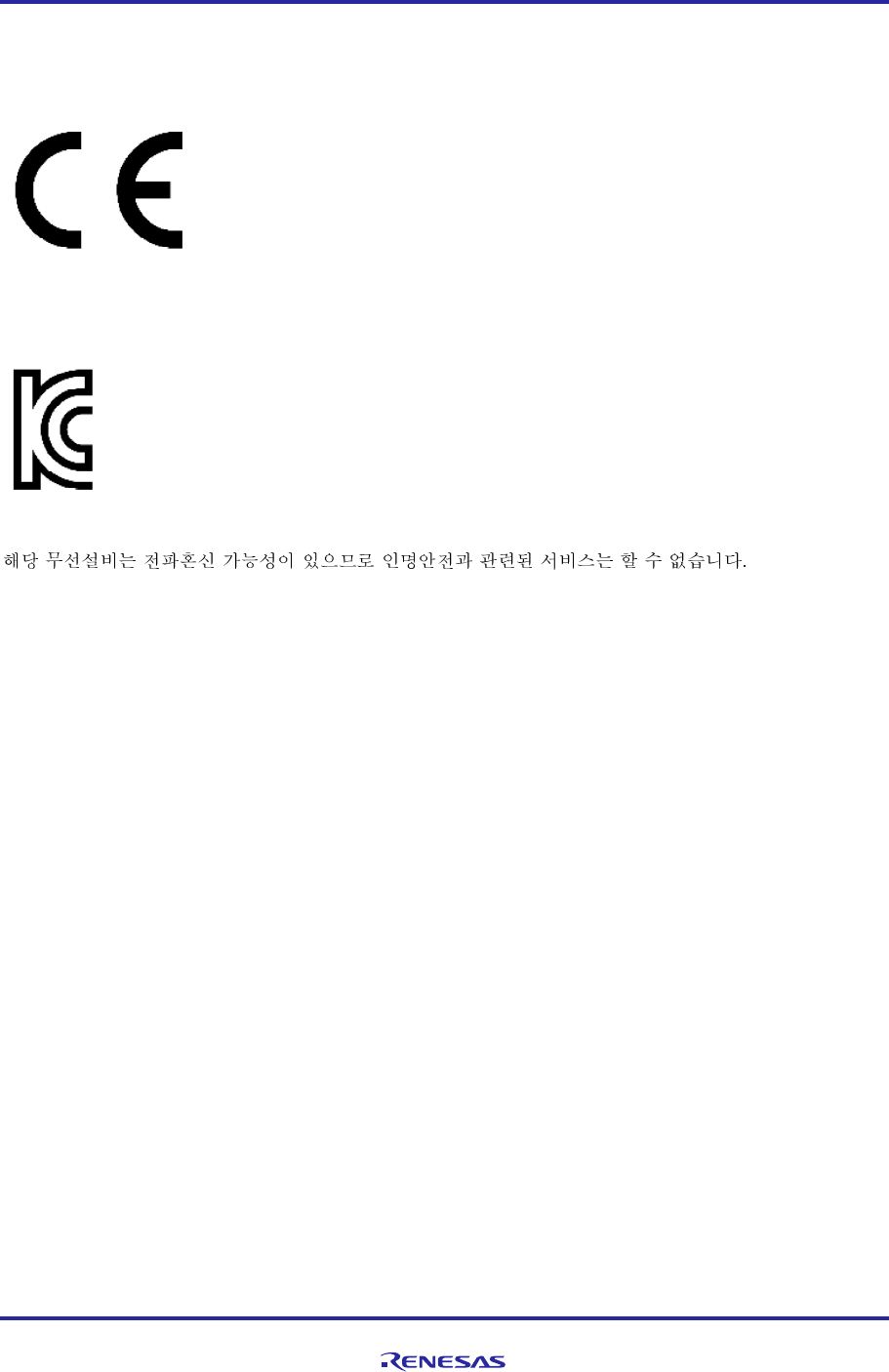
Appendix B - Conformity Assessment
FCC/IC Regulatory
Since this module is not sold to general end users directly, there is no user manual of module.
For the details about this module, please refer to the specification sheet of module.
This module should be installed in the host device according to the interface specification (installation procedure).
The following information must be indicated on the host device of this module;
Contains FCC ID: 2AFST-G1D
This device complies with part 15 of the FCC Rules. Operation is subject to the following two conditions: (1) This
device may not cause harmful interference, and (2) this device must accept any interference received, including
interference that may cause undesired operation.
Contains IC: 20519-G1D
The following statements must be described on the user manual of the host device of this module;
[for FCC]
FCC CAUTION
Changes or modifications not expressly approved by the party responsible for compliance could void the user’s
authority to operate the equipment.
This transmitter must not be co-located or operated in conjunction with any other antenna or transmitter.
This equipment complies with FCC radiation exposure limits set forth for an uncontrolled environment and meets the
FCC radio frequency (RF) Exposure Guidelines. This equipment has very low levels of RF energy that it deemed to
comply without maximum permissive exposure evaluation (MPE). But it is desirable that it should be installed and
operated keeping the radiator at least 20cm or more away from person's body.
[for IC]
This device complies with Industry Canada's licence-exempt RSSs. Operation is subject to the following two
conditions: (1) This device may not cause interference; and (2) This device must accept any interference, including
interference that may cause undesired operation of the device.
Le présent appareil est conforme aux CNR d’Industrie Canada applicables aux appareils radio exempts de licence.
L’exploitation est autorisée aux deux conditions suivantes : 1) l’appareil ne doit pas produire de brouillage; 2)
l’utilisateur de l’appareil doit accepter tout brouillage radioélectrique subi, même si le brouillage est susceptible d’en
compromettre le fonctionnement.
This equipment complies with IC radiation exposure limits set forth for an uncontrolled environment and meets RSS-
102 of the IC radio frequency (RF) Exposure rules. This equipment has very low levels of RF energy that it deemed to
comply without maximum permissive exposure evaluation (MPE). But it is desirable that it should be installed and
operated keeping the radiator at least 20cm or more away from person's body.
Cet équipement est conforme aux limites d’exposition aux rayonnements énoncées pour un environnement non contrôlé
et respecte les règles d’exposition aux fréquences radioélectriques (RF) CNR-102 de l’IC. Cet équipement émet une
énergie RF très faible qui est considérée conforme sans évaluation de l’exposition maximale autorisée. Cependant, il est
souhaitable qu'il devrait être installé et utilisé en gardant une distance de 20 cm ou plus entre le radiateur et le corps
humain.
RL78/G1D RL78/G1D Solution Kit – PMOD Module Hardware Manual
R01AN2919EU0100_RL78G1D Rev. 1.00 Page 10 of 4
Sept. 15, 2015
R&TTE Directive
We hereby declare that this product is in compliance with the essential requirements and other EC relevant provisions
of
Directive 1999/5/EC.
Declaration of Conformity (DoC) can be available upon request. Contact to local Renesas Sale office.
Korea Radio Regulations
MSIP-CRM-R5E-G1D

RL78/G1D RL78/G1D Solution Kit – PMOD Module Hardware Manual
R01AN2919EU0100_RL78G1D Rev. 1.00 Page 11 of 4
Sept. 15, 2015
Website and Support
Renesas Electronics Website
http://www.renesas.com/
Inquiries
http://www.renesas.com/contact/
All trademarks and registered trademarks are the property of their respective owners.

A-1
Revision History
Rev. Date
Description
Page Summary
1.00 Sept. 15, 2015 — First edition issued

General Precautions in the Handling of Microprocessing Unit and Microcontroller Unit Products
The following usage notes are applicable to all Microprocessing unit and Microcontroller unit products from Renesas.
For detailed usage notes on the products covered by this document, refer to the relevant sections of the document as
well as any technical updates that have been issued for the products.
1. Handling of Unused Pins
Handle unused pins in accordance with the directions given under Handling of Unused Pins in the
manual.
The input pins of CMOS products are generally in the high-impedance state. In operation with
an unused pin in the open-circuit state, extra electromagnetic noise is induced in the vicinity of
LSI, an associated shoot-through current flows internally, and malfunctions occur due to the
false recognition of the pin state as an input signal become possible. Unused pins should be
handled as described under Handling of Unused Pins in the manual.
2. Processing at Power-on
The state of the product is undefined at the moment when power is supplied.
The states of internal circuits in the LSI are indeterminate and the states of register settings and
pins are undefined at the moment when power is supplied.
In a finished product where the reset signal is applied to the external reset pin, the states of
pins are not guaranteed from the moment when power is supplied until the reset process is
completed.
In a similar way, the states of pins in a product that is reset by an on-chip power-on reset
function are not guaranteed from the moment when power is supplied until the power reaches
the level at which resetting has been specified.
3. Prohibition of Access to Reserved Addresses
Access to reserved addresses is prohibited.
The reserved addresses are provided for the possible future expansion of functions. Do not
access these addresses; the correct operation of LSI is not guaranteed if they are accessed.
4. Clock Signals
After applying a reset, only release the reset line after the operating clock signal has become
stable. When switching the clock signal during program execution, wait until the target clock signal
has stabilized.
When the clock signal is generated with an external resonator (or from an external oscillator)
during a reset, ensure that the reset line is only released after full stabilization of the clock
signal. Moreover, when switching to a clock signal produced with an external resonator (or by
an external oscillator) while program execution is in progress, wait until the target clock signal is
stable.
5. Differences between Products
Before changing from one product to another, i.e. to a product with a different part number, confirm
that the change will not lead to problems.
The characteristics of Microprocessing unit or Microcontroller unit products in the same group
but having a different part number may differ in terms of the internal memory capacity, layout
pattern, and other factors, which can affect the ranges of electrical characteristics, such as
characteristic values, operating margins, immunity to noise, and amount of radiated noise.
When changing to a product with a different part number, implement a system-evaluation test
for the given product.
Notice
1. Descriptions of circuits, software and other related information in this document are provided only to illustrate the operation of semiconductor products and application examples. You are fully responsible for
the incorporation of these circuits, software, and information in the design of your equipment. Renesas Electronics assumes no responsibility for any losses incurred by you or third parties arising from the
use of these circuits, software, or information.
2. Renesas Electronics has used reasonable care in preparing the information included in this document, but Renesas Electronics does not warrant that such information is error free. Renesas Electronics
assumes no liability whatsoever for any damages incurred by you resulting from errors in or omissions from the information included herein.
3. Renesas Electronics does not assume any liability for infringement of patents, copyrights, or other intellectual property rights of third parties by or arising from the use of Renesas Electronics products or
technical information described in this document. No license, express, implied or otherwise, is granted hereby under any patents, copyrights or other intellectual property rights of Renesas Electronics or
others.
4. You should not alter, modify, copy, or otherwise misappropriate any Renesas Electronics product, whether in whole or in part. Renesas Electronics assumes no responsibility for any losses incurred by you or
third parties arising from such alteration, modification, copy or otherwise misappropriation of Renesas Electronics product.
5. Renesas Electronics products are classified according to the following two quality grades: "Standard" and "High Quality". The recommended applications for each Renesas Electronics product depends on
the product's quality grade, as indicated below.
"Standard": Computers; office equipment; communications equipment; test and measurement equipment; audio and visual equipment; home electronic appliances; machine tools; personal electronic
equipment; and industrial robots etc.
"High Quality": Transportation equipment (automobiles, trains, ships, etc.); traffic control systems; anti-disaster systems; anti-crime systems; and safety equipment etc.
Renesas Electronics products are neither intended nor authorized for use in products or systems that may pose a direct threat to human life or bodily injury (artificial life support devices or systems, surgical
implantations etc.), or may cause serious property damages (nuclear reactor control systems, military equipment etc.). You must check the quality grade of each Renesas Electronics product before using it
in a particular application. You may not use any Renesas Electronics product for any application for which it is not intended. Renesas Electronics shall not be in any way liable for any damages or losses
incurred by you or third parties arising from the use of any Renesas Electronics product for which the product is not intended by Renesas Electronics.
6. You should use the Renesas Electronics products described in this document within the range specified by Renesas Electronics, especially with respect to the maximum rating, operating supply voltage
range, movement power voltage range, heat radiation characteristics, installation and other product characteristics. Renesas Electronics shall have no liability for malfunctions or damages arising out of the
use of Renesas Electronics products beyond such specified ranges.
7. Although Renesas Electronics endeavors to improve the quality and reliability of its products, semiconductor products have specific characteristics such as the occurrence of failure at a certain rate and
malfunctions under certain use conditions. Further, Renesas Electronics products are not subject to radiation resistance design. Please be sure to implement safety measures to guard them against the
possibility of physical injury, and injury or damage caused by fire in the event of the failure of a Renesas Electronics product, such as safety design for hardware and software including but not limited to
redundancy, fire control and malfunction prevention, appropriate treatment for aging degradation or any other appropriate measures. Because the evaluation of microcomputer software alone is very difficult,
please evaluate the safety of the final products or systems manufactured by you.
8. Please contact a Renesas Electronics sales office for details as to environmental matters such as the environmental compatibility of each Renesas Electronics product. Please use Renesas Electronics
products in compliance with all applicable laws and regulations that regulate the inclusion or use of controlled substances, including without limitation, the EU RoHS Directive. Renesas Electronics assumes
no liability for damages or losses occurring as a result of your noncompliance with applicable laws and regulations.
9. Renesas Electronics products and technology may not be used for or incorporated into any products or systems whose manufacture, use, or sale is prohibited under any applicable domestic or foreign laws or
regulations. You should not use Renesas Electronics products or technology described in this document for any purpose relating to military applications or use by the military, including but not limited to the
development of weapons of mass destruction. When exporting the Renesas Electronics products or technology described in this document, you should comply with the applicable export control laws and
regulations and follow the procedures required by such laws and regulations.
10. It is the responsibility of the buyer or distributor of Renesas Electronics products, who distributes, disposes of, or otherwise places the product with a third party, to notify such third party in advance of the
contents and conditions set forth in this document, Renesas Electronics assumes no responsibility for any losses incurred by you or third parties as a result of unauthorized use of Renesas Electronics
products.
11. This document may not be reproduced or duplicated in any form, in whole or in part, without prior written consent of Renesas Electronics.
12. Please contact a Renesas Electronics sales office if you have any questions regarding the information contained in this document or Renesas Electronics products, or if you have any other inquiries.
(Note 1) "Renesas Electronics" as used in this document means Renesas Electronics Corporation and also includes its majority-owned subsidiaries.
(Note 2) "Renesas Electronics product(s)" means any product developed or manufactured by or for Renesas Electronics.
http://www.renesas.com
Refer to "http://www.renesas.com/" for the latest and detailed information.
Renesas Electronics America Inc.
2801 Scott Boulevard Santa Clara, CA 95050-2549, U.S.A.
Tel: +1-408-588-6000, Fax: +1-408-588-6130
Renesas Electronics Canada Limited
9251 Yonge Street, Suite 8309 Richmond Hill, Ontario Canada L4C 9T3
Tel: +1-905-237-2004
Renesas Electronics Europe Limited
Dukes Meadow, Millboard Road, Bourne End, Buckinghamshire, SL8 5FH, U.K
Tel: +44-1628-585-100, Fax: +44-1628-585-900
Renesas Electronics Europe GmbH
Arcadiastrasse 10, 40472 Düsseldorf, Germany
Tel: +49-211-6503-0, Fax: +49-211-6503-1327
Renesas Electronics (China) Co., Ltd.
Room 1709, Quantum Plaza, No.27 ZhiChunLu Haidian District, Beijing 100191, P.R.China
Tel: +86-10-8235-1155, Fax: +86-10-8235-7679
Renesas Electronics (Shanghai) Co., Ltd.
Unit 301, Tower A, Central Towers, 555 Langao Road, Putuo District, Shanghai, P. R. China 200333
Tel: +86-21-2226-0888, Fax: +86-21-2226-0999
Renesas Electronics Hong Kong Limited
Unit 1601-1611, 16/F., Tower 2, Grand Century Place, 193 Prince Edward Road West, Mongkok, Kowloon, Hong Kong
Tel: +852-2265-6688, Fax: +852 2886-9022
Renesas Electronics Taiwan Co., Ltd.
13F, No. 363, Fu Shing North Road, Taipei 10543, Taiwan
Tel: +886-2-8175-9600, Fax: +886 2-8175-9670
Renesas Electronics Singapore Pte. Ltd.
80 Bendemeer Road, Unit #06-02 Hyflux Innovation Centre, Singapore 339949
Tel: +65-6213-0200, Fax: +65-6213-0300
Renesas Electronics Malaysia Sdn.Bhd.
Unit 1207, Block B, Menara Amcorp, Amcorp Trade Centre, No. 18, Jln Persiaran Barat, 46050 Petaling Jaya, Selangor Darul Ehsan, Malaysia
Tel: +60-3-7955-9390, Fax: +60-3-7955-9510
Renesas Electronics India Pvt. Ltd.
No.777C, 100 Feet Road, HALII Stage, Indiranagar, Bangalore, India
Tel: +91-80-67208700, Fax: +91-80-67208777
Renesas Electronics Korea Co., Ltd.
12F., 234 Teheran-ro, Gangnam-Gu, Seoul, 135-080, Korea
Tel: +82-2-558-3737, Fax: +82-2-558-5141
SALES OFFICES
© 2015 Renesas Electronics Corporation. All rights reserved.
Colophon 5.0