Renishaw plc RLP40 PROBE FOR MACHINE TOOLS User Manual
Renishaw plc PROBE FOR MACHINE TOOLS Users Manual
Users Manual
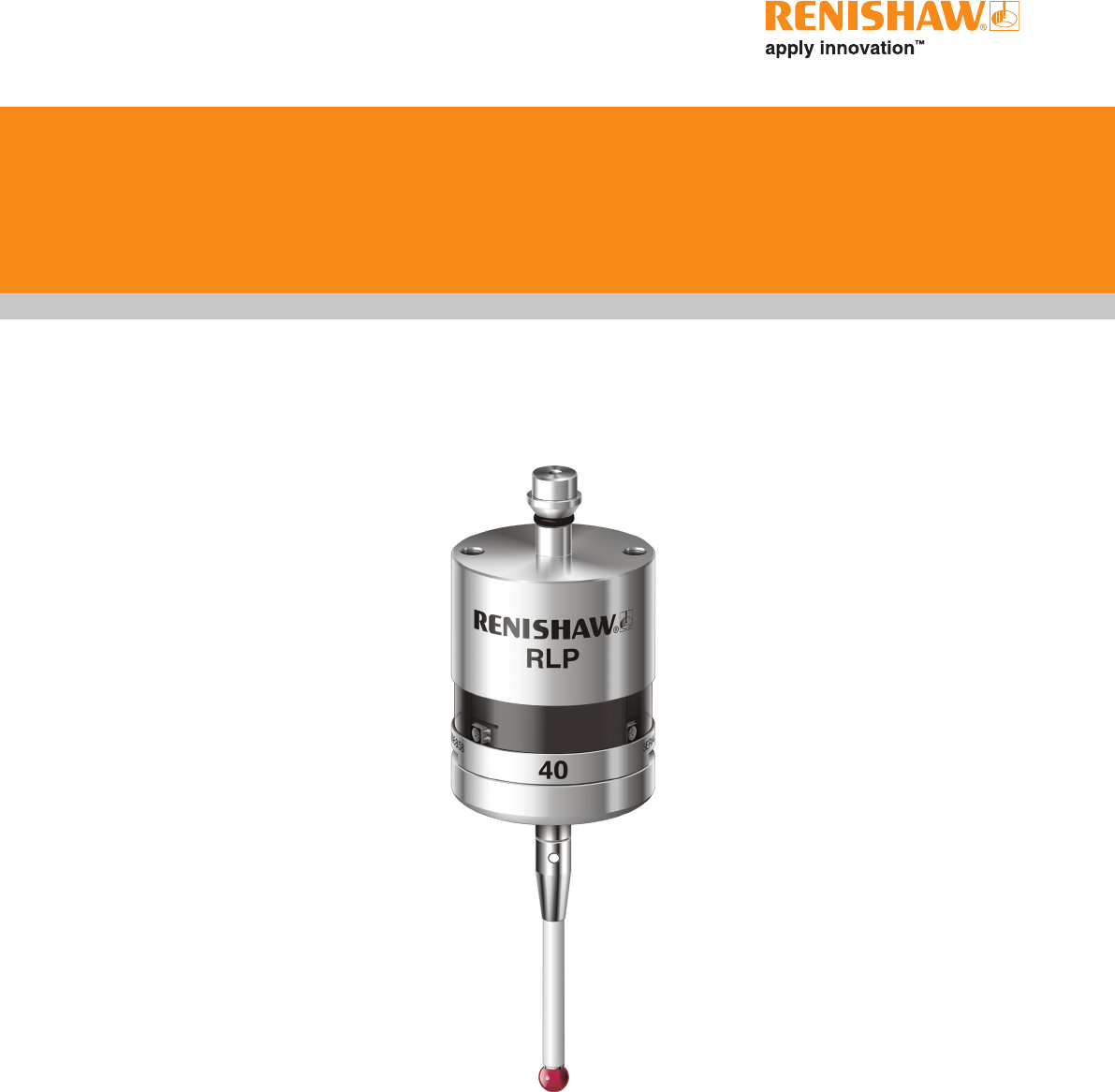
RLP40 - radio lathe probe
Installation guide
H-5627-8504-01-A

Renishaw part no: H-5627-8504-01-A
First issued: 01.10
© 2010 Renishaw plc. All rights reserved.
This document may not be copied or reproduced
in whole or in part, or transferred to any other
media or language, by any means, without the
prior written permission of Renishaw plc.
The publication of material within this document
does not imply freedom from the patent rights of
Renishaw plc.

i
Contents
Contents
Before you begin
Before you begin ............................................................1.1
Disclaimer ..............................................................1.1
Trademarks .............................................................1.1
Warranty ................................................................1.1
Changes to equipment .....................................................1.1
CNC machines ...........................................................1.1
Care of the probe .........................................................1.1
Patents .................................................................1.2
EC Declaration of Conformity ..................................................1.3
WEEE DIRECTIVE ..........................................................1.3
FCC DECLARATION (USA) ...................................................1.3
Radio approval .............................................................1.4
Safety ....................................................................1.5
RLP40 basics
Introduction ................................................................2.1
Getting started ...........................................................2.1
System interface ..........................................................2.1
Trigger Logic™ ...........................................................2.2
Modes of operation ..........................................................2.2
Configurable settings .........................................................2.2
Switch on/switch off methods ................................................2.2
Enhanced trigger filter .....................................................2.2
Multiple probe mode .......................................................2.4
Acquisition mode .........................................................2.4
RLP40 dimensions ..........................................................2.5
RLP40 specification ..........................................................2.6

RLP40 installation guide
ii
Contents
System installation
Installing the RLP40 with an RMI ...............................................3.1
Operating envelope .......................................................3.1
Performance envelope when using the RLP40 with the RMI ........................3.2
RLP40 / RMI positioning ...................................................3.2
Performance envelope .....................................................3.2
Preparing the RLP40 for use ...................................................3.3
Fitting the stylus ..........................................................3.3
Installing the batteries .....................................................3.4
Mounting the probe on a shank ..............................................3.5
Stylus on-centre adjustment .................................................3.6
Stylus trigger force adjustment ...............................................3.7
Calibrating the RLP40 ........................................................3.8
Why calibrate a probe? ....................................................3.8
Calibrating in a bored hole or on a turned diameter ...............................3.8
Calibrating the probe length .................................................3.8
Trigger Logic™
Reviewing the current probe settings ............................................4.1
Multiple probe settings .......................................................4.2
Probe settings record ........................................................4.3
Changing the probe settings ...................................................4.4
RLP40 – RMI partnership .....................................................4.6
Operating mode .............................................................4.7
Maintenance
Maintenance ...............................................................5.1
Cleaning the probe ..........................................................5.1
Changing the batteries .......................................................5.2
Battery type ................................................................5.3
RLP40 eyelid ...............................................................5.4
Re-assembling the probe ...................................................5.4
Fault finding
Parts list

1.1
Before you begin
Disclaimer
RENISHAW HAS MADE CONSIDERABLE
EFFORTS TO ENSURE THE CONTENT OF THIS
DOCUMENT IS CORRECT AT THE DATE OF
PUBLICATION BUT MAKES NO WARRANTIES
OR REPRESENTATIONS REGARDING
THE CONTENT. RENISHAW EXCLUDES
LIABILITY, HOWSOEVER ARISING, FOR ANY
INACCURACIES IN THIS DOCUMENT.
Trademarks
RENISHAW® and the probe emblem used in the
RENISHAW logo are registered trademarks of
Renishaw plc in the UK and other countries.
apply innovation™ and Trigger Logic™ are
trademarks of Renishaw plc.
All other brand names and product names used
in this document are trade names, service marks,
trademarks, or registered trademarks of their
respective owners.
Warranty
Equipment requiring attention under warranty
must be returned to your equipment supplier.
No claims will be considered where Renishaw
equipment has been misused, or where
repairs or adjustments have been attempted by
unauthorised persons. Prior consent must be
obtained in instances where Renishaw equipment
is to be substituted or omitted. Failure to comply
with this requirement will invalidate the warranty.
Changes to equipment
Renishaw reserves the right to change equipment
specifications without notice.
CNC machines
CNC machine tools must always be operated by
fully trained personnel in accordance with the
manufacturer's instructions.
Care of the probe
Keep system components clean and treat the
probe as a precision tool.
Before you begin

RLP40 installation guide
1.2
Before you begin
Patents
Features of the RLP40 probe, and other similar
Renishaw probes, are subject of one or more of the
following patents and/or patent applications:
CN 100466003
CN 101287958
CN 101482402
EP 0652413
EP 0695926
EP 1185838
EP 1373995
EP 1425550
EP 1457786
EP 1477767
EP 1477768
EP 1576560
EP 1701234
EP 1734426
EP 1804020
EP 1931936
EP 1988439
IN 2004-057552
IN 2004-057552
IN 2007-028964
IN 215787
JP 2004-279417
JP 2008-203270
JP 3126797
JP 3967592
JP 2004-522961
JP 2006-313567
JP 2006-511860
JP 2009-507240
JP 4237051
TW 200720626
US. 5150529
US. 5279042
US. 5669151
US. 7285935
US. 6776344
US. 2006-0215614
US. 2009-0049704
US. 2009-0130987
US. 6776344
US. 6941671
US. 7145468
US. 7441707
US. 7486195

1.3
Before you begin
FCC DECLARATION (USA)
FCC Section 15.19
This device complies with Part 15 of the FCC
rules.
Operation is subject to the following two
conditions:
1. This device may not cause harmful
interference.
2. This device may accept any interference
received, including interference that may
cause undesired operation.
FCC Section 15.105
This equipment has been tested and found to
comply with the limits for a Class A digital device,
pursuant to Part 15 of the FCC rules. These limits
are designed to provide reasonable protection
against harmful interference when the equipment
is operated in a commercial environment. This
equipment generates, uses, and can radiate
radio frequency energy and, if not installed
and used in accordance with the instruction
manual, may cause harmful interference to radio
communications. Operation of this equipment
in a residential area is likely to cause harmful
interference, in which case you will be required to
correct the interference at your own expense.
FCC Section 15.21
The user is cautioned that any changes or
modifications not expressly approved by
Renishaw plc, or authorised representative could
void the user’s authority to operate the equipment.
C
Renishaw PLC hereby declares that the RLP40 is
in compliance with the essential requirements and
other relevant provisions of Directive 1999/5/EC.
Contact Renishaw PLC at
www.renishaw.com/rlp40/cert
for the full EC Declaration of Conformity.
WEEE DIRECTIVE
The use of this symbol on Renishaw products
and/or accompanying documentation indicates
that the product should not be mixed with
general household waste upon disposal. It is the
responsibility of the end user to dispose of this
product at a designated collection point for waste
electrical and electronic equipment (WEEE) to
enable reuse or recycling. Correct disposal of
this product will help to save valuable resources
and prevent potential negative effects on the
environment. For more information, please contact
your local waste disposal service or Renishaw
distributor.

RLP40 installation guide
1.4
Before you begin
Radio approval
PENDING RADIO APPROVAL

1.5
Before you begin
Safety
Information to the user
The RLP40 is supplied with two non-rechargeable
½ AA lithium metal batteries. Once the charge
in these batteries is depleted, please dispose of
them in accordance with your local environmental
and safety laws. Do not attempt to re-charge these
batteries.
Please ensure replacement batteries are of the
correct type and are fitted with the correct polarity
in accordance with the instructions in this manual
and as indicated on the product. For specific
battery operating, safety and disposal guidelines,
please refer to the battery manufacturers'
literature.
• Ensurethatallbatteriesareinsertedwith
the correct polarity.
• Donotstoreindirectsunlightorrain.
• Donotheatordisposeofthebatteryinfire.
• Avoidforceddischargeofthebattery.
• Donotshortcircuit.
• Donotdisassemble,applyexcessive
pressure, pierce or deform.
• Donotswallowandkeepoutofreachof
children.
• Donotgetbatterywet.
If battery is damaged, exercise caution when
handling.
Please ensure that you comply with international
and national battery transport regulations when
transporting batteries or the products. Lithium
batteries are classified as dangerous goods and
strict controls apply on their shipment by air. To
reduce the risk of shipment delays, should you
need to return the products to Renishaw for any
reason, do not return any batteries.
The RLP40 has a glass window. Handle with care
if broken to avoid injury.
Information to the machine supplier/
installer
It is the machine supplier's responsibility to ensure
that the user is made aware of any hazards
involved in operation, including those mentioned
in Renishaw product literature, and to ensure
that adequate guards and safety interlocks are
provided.
Under certain circumstances, the probe signal
may falsely indicate a probe seated condition. Do
not rely on probe signals to halt the movement of
the machine.
Information to the equipment installer
All Renishaw equipment is designed to comply
with the relevant EEC and FCC regulatory
requirements. It is the responsibility of the
equipment installer to ensure that the following
guidelines are adhered to, in order for the product
to function in accordance with these regulations:
• any interface MUST be installed in a position
away from any potential sources of electrical
noise, i.e. power transformers, servo drives
etc;
• all ground connections should be connected
to the machine 'star point' (the 'star point'
is a single point return for all equipment
ground and screen cables). This is very
important and failure to adhere to this
can cause a potential difference between
grounds;
• all screens must be connected as outlined in
the user instructions;
• cables must not be routed alongside high
current sources, i.e. motor power supply
cables etc, or be near high speed data lines;
• cable lengths should always be kept to a
minimum.
Equipment operation
If this equipment is used in a manner not specified
by the manufacturer, the protection provided by
the equipment may be impaired.
!

RLP40 installation guide
1.6
Before you begin
This page left intentionally blank

2.12.1
Introduction
Welcome to the RLP40 job set-up and inspection
probe. At only 40 mm diameter, this compact
probe sets industry standards for functionality,
reliability and robustness in the harshest of
machine tool environments.
RMP40 forms part of Renishaw's family of new
generation radio transmission probes, It is ideally
suited to large machining centres, where line-of-
sight between probe and receiver is difficult to
achieve or where Z travel is limited.
RLP40 complies with FCC regulations and
operates in the 2.4 GHz band. It delivers
interference-free transmission through the use of
FHSS (Frequency Hopping Spread Spectrum).
This allows many systems to operate in the same
machine shop without risk of cross-interference.
All RLP40 settings are configured using ‘Trigger
Logic’. This technique enables the user to review
and subsequently change probe settings by
deflecting the stylus whilst observing the LED
display.
Configurable settings are:
• Radio on / Radio off
• Radio on / Timer off
• Spin on / Spin off
• Spin on / Timer off
• Filter on / Filter off
• Multiple probe mode on / multiple probe
mode off
Getting started
Three multicolour LEDs provide visual indication
of selected probe settings.
For example:
• Switch-on and switch-off methods
• Probe status - triggered or seated
• Battery condition
Batteries are inserted or removed as shown (see
‘RLP40 batteries’ for further information).
On insertion of batteries, the LEDs will begin to
flash (see ‘Reviewing current probe settings’ for
further information).
System interface
The RMI integrated interface/receiver is used to
communicate between the RLP40 probe and the
machine control.
RLP40 basics

RLP40 installation guide
2.2
RLP40 basics
Trigger Logic™
Trigger Logic™ (see Section 4, "Trigger Logic™")
is a method that allows the user to view and select
all available mode settings in order to customise a
probe to suit a specific application. Trigger Logic™
is activated by battery insertion and subsequent
stylus deflection. A sequence of stylus deflection
(triggering) is then used to systematically lead
the user through the available choices to allow
selection of the required mode options.
Current probe settings can be reviewed by
simply removing the batteries for a minimum of
5 seconds, and then replacing them to activate
the Trigger Logic™ review sequence.
Modes of operation
The RLP40 probe can be in one of three modes:
Standby mode: where the probe is awaiting a
switch on signal.
Operational mode: activated by one of the switch
on methods described on this page. In this mode
the RLP40 is ready for use.
Configuration mode: where Trigger Logic™ may
be used to configure the following probe settings.
Configurable settings
Switch on/switch off methods
The following switch on/switch off options are
user-configurable.
1. Radio on/Radio off
2. Radio on/Timer off
3. Spin on/Spin off
4. Spin on/Timer off
Enhanced trigger filter
Probes subjected to high levels of vibration or
shock loads may output signals without having
contacted any surface. The enhanced trigger filter
improves the probes resistance to these effects.
When the filter is enabled, a constant 10 ms delay
is introduced to the probe output.
The RLP40 is factory set to trigger filter off.
NOTE: It may be necessary to reduce the probe
approach speed to allow for the increased stylus
overtravel during the extended time delay.

2.3
RLP40 basics
RLP40 switch on method
Switch on options are configurable
RLP40 switch off method
Switch off options are configurable
Switch on time
Radio on
Radio switch on is commanded by
machine input.
Radio off
Radio switch off is commanded by
machine input. A timer automatically
switches the probe off 90 minutes
after the last trigger if it is not turned
off by machine input.
Timer off (timeout)
Timeout will occur 12, 33 or 134
seconds (user configurable) after the
last probe trigger or reseat.
1 second maximum
Note: This assumes
a good radio
communication link.
In a poor RF
environment this may
rise to a maximum of
3 seconds.
Spin on
Spin at 500 rev/min for 1 second
minimum (6 seconds maximum).
Spin off
Spin at 500 rev/min for 1 second
minimum (6 seconds maximum).
A timer automatically switches the
probe off 90 minutes after the last
trigger if it is not spun.
Timer off (timeout)
Timeout will occur 12, 33 or 134
seconds (user configurable) after the
last probe trigger or reseat.
2 seconds maximum.
Note: The 2 seconds
starts from the
moment the spindle
reaches 500 rev/min.
NOTE: After being switched on, the RLP40 must be on for 1 second minimum (the RLP40 must be
spun down before it can be spun off again) before being switched off.

RLP40 installation guide
2.4
RLP40 basics
Multiple probe mode
The RLP40 can be configured, using Trigger
Logic™, to allow multiple radio probes to be used
with a single RMI.
NOTES:
The 'radio on' switch on method cannot be used
in multiple probe mode. Multiple probe mode will
not appear as an option if the 'radio on' option has
been selected.
RLP40 probes which are set to 'multiple probe
mode on' can coexist alongside any number of
RLP40 probes set to 'mode off'.
To allow multiple radio probes to work in close
proximity, and with a single RMI, 16 choices of
'mode on' colours are available, each representing
a different machine tool installation. The colour
choices available are as shown on page 4.2.
All probes operating with a single RMI must be set
to the same 'mode on' colour choice; any multiple
probes located on adjacent machines must all be
set to an alternative 'mode on' colour choice.
Only one probe per 'mode on' colour choice needs
to be partnered with the RMI as, by configuring
multiple probes to a single 'mode on' colour
choice, all probes using this 'mode on' colour
choice will have the same identity. The probe to be
partnered is partnered after selecting the 'multiple
probe mode' setting and choosing the 'mode
on' option. See 'Changing the probe settings' in
Section 4, "Trigger Logic™".
There is no limit to the number of probes that can
be used with a single RMI so long as they all have
the same 'mode on' colour choice.
All RLP40 probes are factory set to 'mode off'.
The addition of any further probe(s) into a single
probe installation will require that all probes are
reconfigured to the same 'mode on' colour choice
and that one of the probes is then repartnered
with the RMI.
The addition of any further probe(s), or
replacements, into a multi-probe installation can
be achieved simply through the reconfiguration of
the probe to the same 'mode on' colour choice.
Acquisition mode
System set-up is achieved using Trigger Logic™
and powering on the RMI.
Partnering is only required during initial system
set-up. Further partnering is only required if either
the RLP40 or RMI is changed.
Partnering will not be lost by reconfiguration of
probe settings or when changing batteries, except
where multiple probe mode is selected.
Partnering can take place anywhere within the
operating envelope.
M-5625-1014
4
3
7
9
8
M-5625-1014
4
3
7
9
8
2.5
RLP40 basics
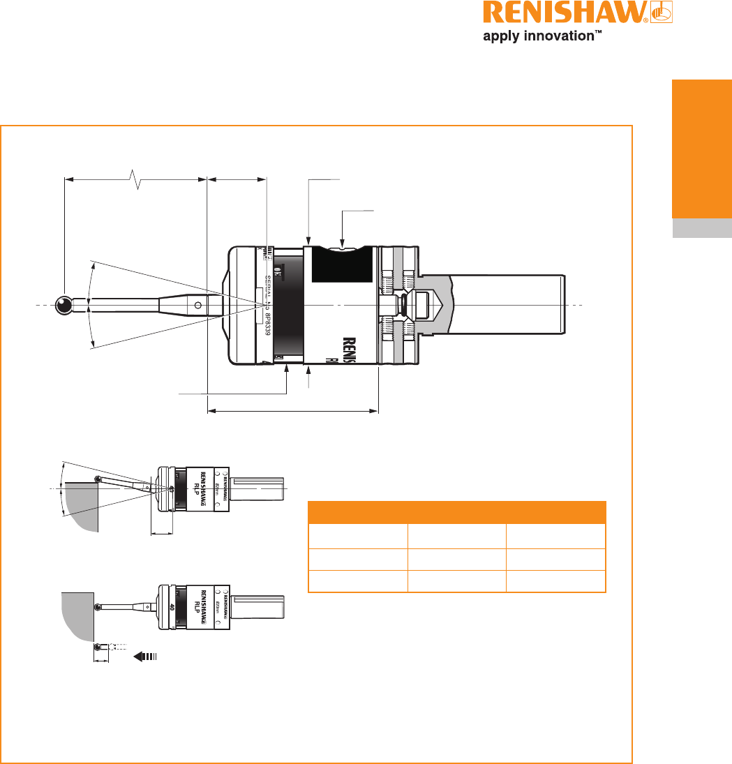
RLP40 dimensions
Battery cassette
50 (1.97)
Dimensions given in mm (in)
19 (0.75)
M4 stylus
Ø40 (Ø1.57)
RLP40 window
58.3 (2.30)
A range of probe-ready
shanks is available from
Renishaw
Stylus overtravel limits
Stylus length ±X/±Y +Z
50 (1.97) 12 (0.47) 6 (0.24)
100 (3.94) 22 (0.87) 6 (0.24)
12.5°
12.5°
±X
±Y
+Z

RLP40 installation guide
2.6
RLP40 basics
RLP40 specification
§ Using a 50 mm (1.97 in) straight stylus.
Principal application Workpiece inspection and job setup on turning centres
Dimensions
Length
Diameter
58.3 mm (2.30 in)
40 mm (1.57 in)
Weight (without shank)
With batteries
Without batteries
260 g (9.17 oz)
240 g (8.47 oz)
Transmission type Frequency Hopping Spread Spectrum (FHSS) radio
Radio frequency 2400 MHz to 2483.5 MHz
Switch ON methods Radio 'M' code, spin
Switch OFF methods Radio 'M' code, spin, time out
Spindle speed
(maximum)
1000 rev/min
Operating range Up to 15 m (49.2 ft)
Receiver/interface RMI combined antenna, interface and receiver unit
Sense directions Omni-directional ±X, ±Y, +Z
Uni-directional
repeatability
maximum 2σ value in
any direction
1.0 µm (0.00004 in) is certified at 480 mm/min (1.57 ft/min) using a
50 mm (1.97 in) long stylus.
Stylus trigger force
(Factory setting§)
XY low force
XY high force
Z
(Maximum setting§)
XY low force
XY high force
Z
(Minimum setting§)
XY low force
XY high force
Z
0.4 N, 40 gf (1.4 ozf)
0.8 N, 80 gf (2.8 ozf)
5.3 N, 530 gf (18.7 ozf)
0.8 N, 80 gf (2.8 ozf)
1.6 N, 160 gf (5.6 ozf)
10.0 N, 1000 gf (35.3 ozf)
0.3 N, 30 gf (1.1 ozf)
0.6 N, 60 gf (2.1 ozf)
4.0 N, 400 gf (14.1 ozf)
The stylus trigger force is the force exerted
on the component when the probe triggers.
However, the maximum force applied to
the component will occur after the trigger
point and will be greater than the trigger
force. The magnitude depends on a
number of factors affecting probe overtravel
including measuring speed and machine
deceleration. If the forces applied to the
component are critical, contact Renishaw
for further information.
Stylus overtravel
XY plane
+Z plane
±12.5°
6 mm (0.24 in)

2.7
RLP40 basics
Typical battery life
Battery type Spin switch on Radio switch on Continuous use
Standby life 5% usage
(72 minutes/day)
Standby life 5% usage
(72 minutes/day)
Lithium Thionyl
Chloride 240 days 150 days 290 days 170 days 450 hours
Environment
(As defined in
BS EN 61010 - 1:2001)
IP rating IPX8 (BS5490, IEC 60529) 1 atmosphere
Storage temperature -10 °C to 70 °C (14 °F to 158 °F)
Operating temperature 5 °C to 50 °C (41 °F to 122 °F)
Altitude Exceeds 2000 m
Pollution degree 3
Relative humidity No humidity restriction
Indoor use only
Battery types 2 x 1/2 AA (3.6V) Lithium Thionyl Chloride
Battery reserve life Approximately one week after a low battery warning is first given
Low battery indication Blue flashing LED in conjunction with normal red or green probe status
LED
Dead battery indication Constant or flashing red
RLP40 specification (continued)

RLP40 installation guide
2.8
RLP40 basics
This page left intentionally blank
3.1
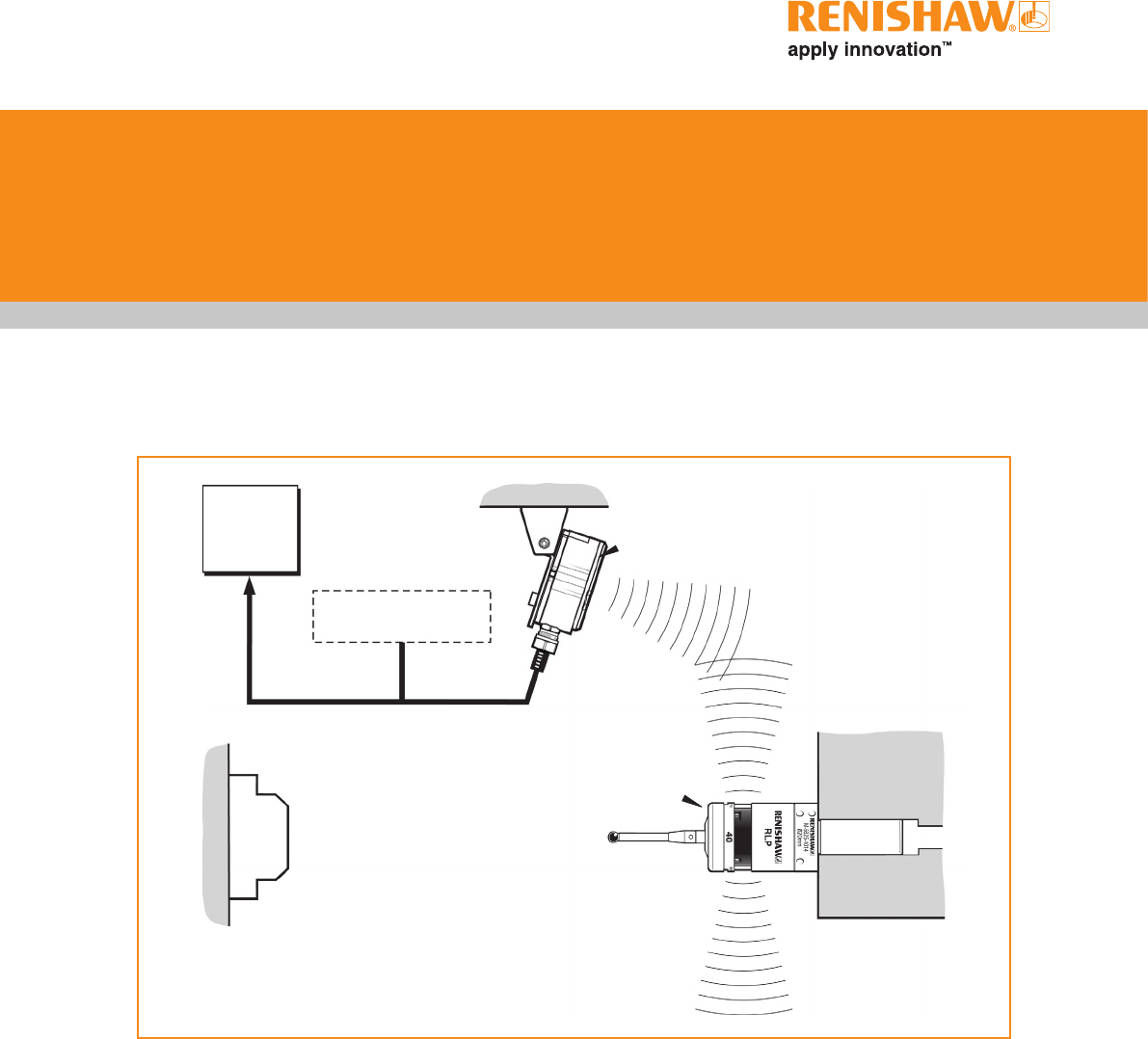
Installing the RLP40 with an RMI
Lathe turret
RLP40 inspection
probe
RMI
interface
RMI mounting
bracket
CNC
machine
control
PSU3 power supply
unit (optional)
Cable
Workpiece Stylus
System installation
Operating envelope
Radio transmission does not require line-of-sight
and will pass through small gaps and machine
tool windows. This allows easy installation, either
inside or outside the machine enclosure.
Coolant and swarf residue accumulating on the
RLP40 and RMI may have a detrimental effect
on transmission performance. Wipe clean as
often as is necessary to maintain unrestricted
transmission.
When operating, do not touch either the RMI
cover or the probe glass window with your hand,
as this will affect the performance.
Some reduction in range may result when
operating in temperatures of 0 °C to 5 °C (32 °F to
41 °F) and 50 °C to 60 °C (122 °F to 140 °F).
RLP40 installation guide
3.2
System
installation
M-5625-1014
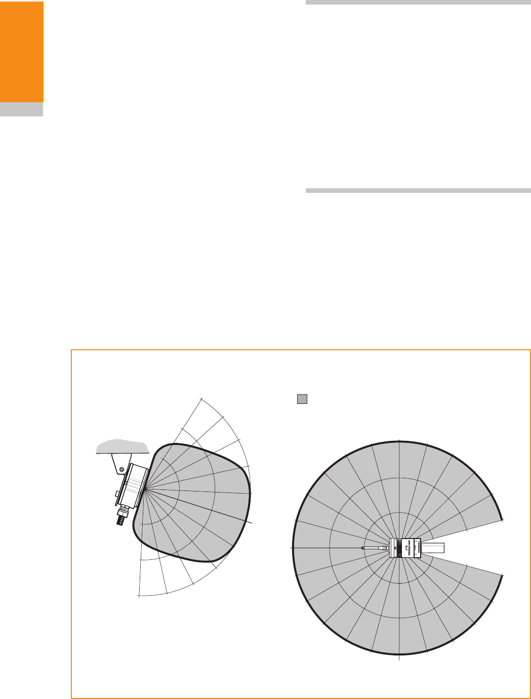
Performance envelope when using the
RLP40 with the RMI
RLP40 / RMI positioning
The probe system should be positioned so that
the optimum range can be achieved over the full
travel of the machine's axes. Always face the front
cover of the RMI in the general direction of the
machining area and the tool magazine, ensuring
both are within the performance envelope shown
below. To assist in finding the optimum position of
the RMI, the signal quality is displayed on an RMI
signal LED.
Range metres (feet)
OPERATING AND SWITCH ON/OFF
75°
60°
45°
30°
15°
0°
15°
30°
45°
60°
75° 90°
90°
75°
60°
45°
30°
15°
0°
15°
45°
60°
75°
75°
60°
45°
30°
30°
45°
60°
75°
10 (33)
15 (49)
5 (16)
5 (16)
10 (33)
15 (49)
15° 0°
15°
30°
5
(16)
10
(33)
15
(49)
RLP40
RMI
NOTE: RLP40 / RMI installation with RLP40 in
radio-on configuration.
RLP40 has a built-in hibernate mode (battery
saving mode) that saves battery life when the RMI
is unpowered in radio-on (radio-off or time-off)
configurations. The RLP40 goes into hibernate
mode 30 seconds after the RMI is unpowered (or
the RLP40 is out of range). When in hibernate
mode, the RLP40 checks for a powered RMI
every 30 seconds. If found, the RLP40 goes from
hibernate mode to stand-by mode, ready for
radio-on.
Performance envelope
The RLP40 and RMI must be within each
other's performance envelope as shown below.
The performance envelope shows line-of-sight
performance, however radio transmission does
not require this providing a reflected path (of less
than 15 m (49.2 ft)) is available.
1
2
3.3
System
installation
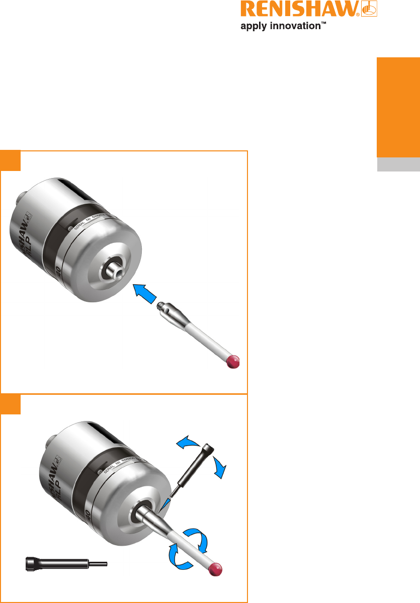
Preparing the RLP40 for use
Fitting the stylus
M-5000-3707
RLP40 installation guide
3.4
System
installation
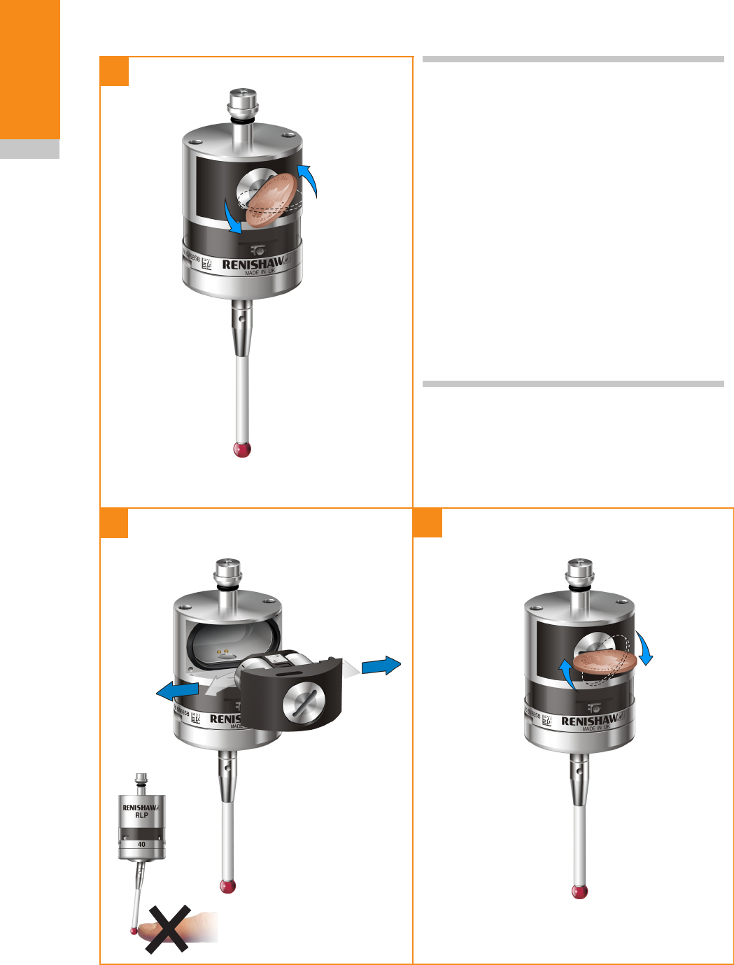
Installing the batteries
1
23
NOTES:
See Section 5 - Maintenance for list of suitable
battery types.
When inserting batteries, check that the battery
polarity is correct.
If dead batteries are inadvertently inserted into
the probe then the LEDs will remain a constant
red, see page 4.4.
Do not allow coolant or debris to enter the
battery compartment.
After inserting the batteries the LEDs will display
the current probe settings (for details see
Section 4 - Trigger Logic™).
Please remove battery
isolation device from the
battery compartment,
before use.
3.5
System
installation
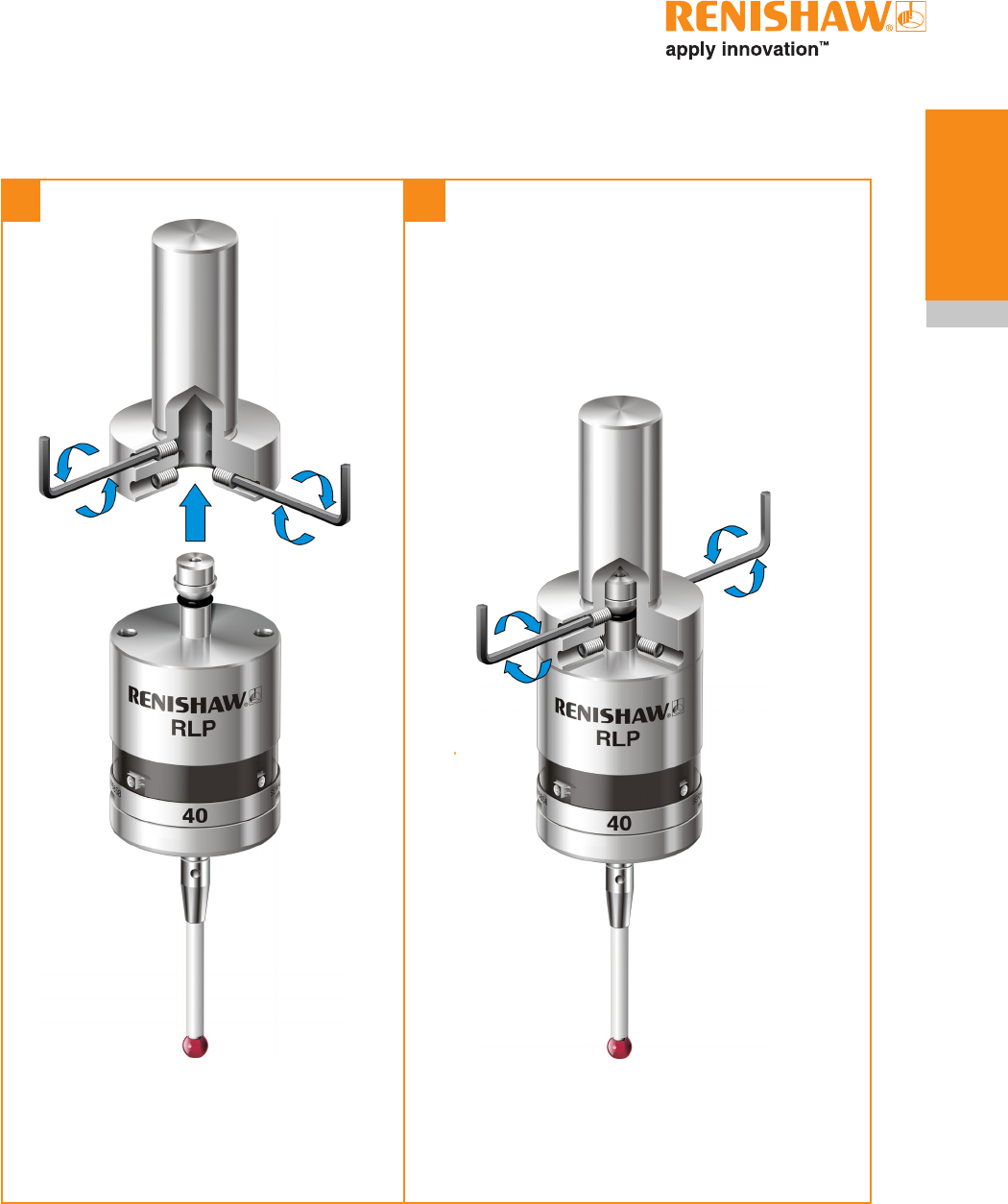
Mounting the probe on a shank
1 2
2 mm AF
0.5 Nm - 1.5 Nm
(0.37 lbf.ft - 1.1 lbf.ft)
(x 2)
RLP40 installation guide
3.6
System
installation
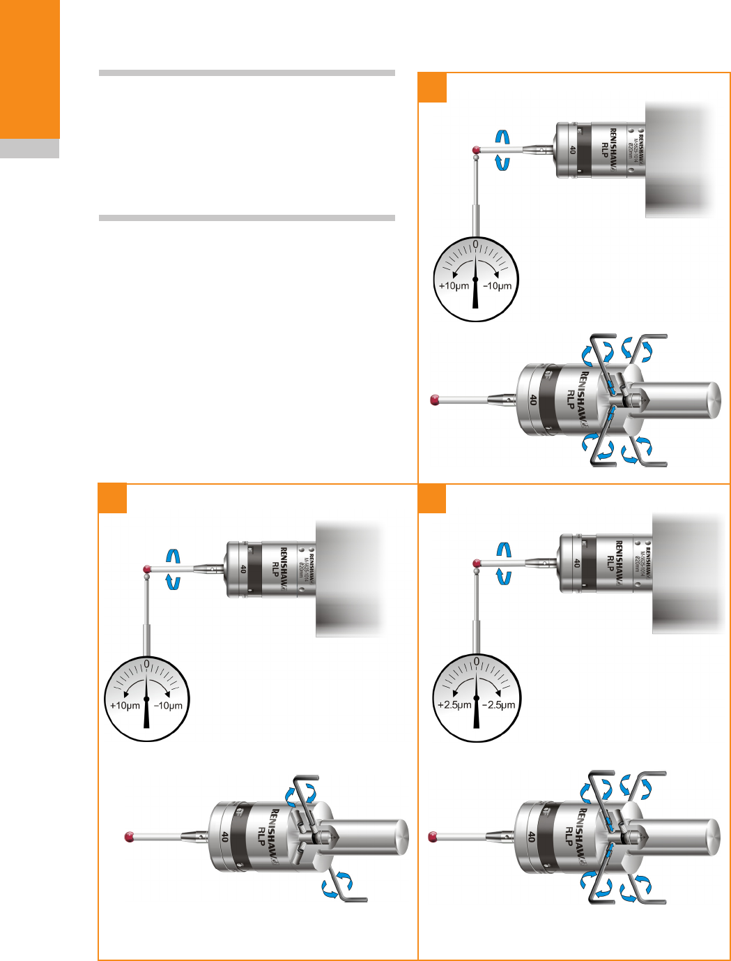
Stylus on-centre adjustment
23
2 mm AF
1.5 Nm - 2.2 Nm
(1.1 lbf.ft - 1.62 lbf.ft)
(x2)
2 mm AF
1.5 Nm - 2.2 Nm
(1.1 lbf.ft - 1.62 lbf.ft)
(x4 )
NOTES:
If a probe and shank assembly is dropped,
it must be rechecked for correct on-centre
adjustment.
Do not hit or tap the probe to achieve on-centre
adjustment.
1
2 mm AF
0.5 Nm - 1.5 Nm
(0.37 lbf.ft - 1.1 lbf.ft)
(x4)
3.7
System
installation
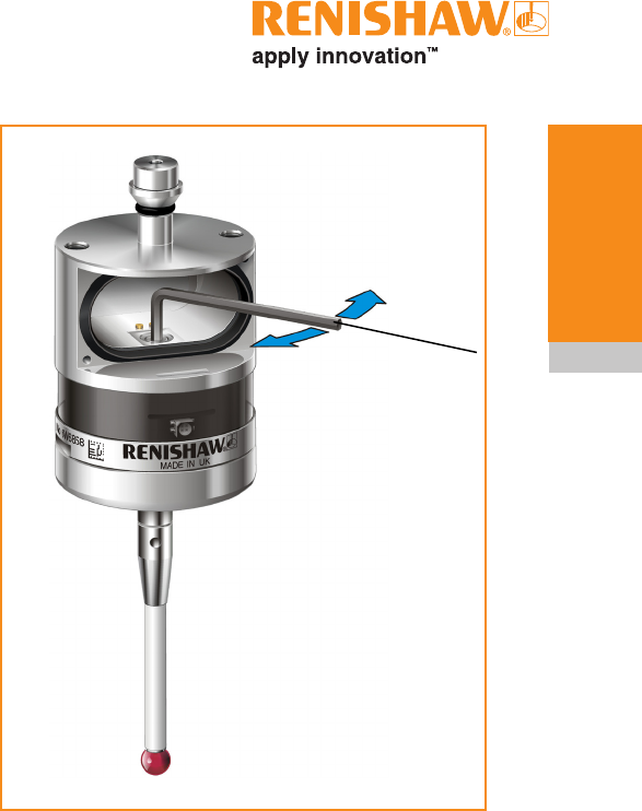
Stylus trigger force adjustment
Spring force within the probe causes the stylus to
sit in a unique position and return to this position
following each stylus deflection.
Stylus trigger force is set by Renishaw. The
user should only adjust trigger force in special
circumstances e.g. where there is excessive
machine vibration or insufficient force to support
the stylus weight.
To adjust the trigger force, turn the adjusting
screw anticlockwise (as shown) to reduce the
force (more sensitive); eventually it reaches a
stop. Turn the adjusting screw clockwise (as
shown) to increase the force (less sensitive). If
the internal screw becomes disengaged, remove
any pressure on the stylus and turn the key
anticlockwise to re-engage the thread.
Trigger forces in the XY plane vary around the
stylus and depend on trigger direction.
Stylus trigger force adjustment and use of
styli other than test stylus types may cause
probe repeatability to differ from the calibration
certificate results.
Factory setting
XY low force 0.4 N / 40 gf (1.4 ozf)
XY high force 0.8 N / 80 gf (2.8 ozf)
Z 5.3 N / 530 gf (18.7 ozf)
Maximum setting
XY low force 0.8 N / 80 gf (2.8 ozf)
XY high force 1.6 N / 160 gf (5.6 ozf)
Z 10.0 N / 1000 gf (36.3 ozf)
Minimum setting
XY low force 0.3 N / 30 gf (1.1 ozf)
XY high force 0.6 N / 60 gf (2.1 ozf)
Z 4.0 N 400 gf (14.1 ozf)
2 mm
AF
Reduce
force
Increase
force

RLP40 installation guide
3.8
System
installation
Calibrating the RLP40
Why calibrate a probe?
A spindle probe is just one component of the
measurement system which communicates with
the machine tool. Each part of the system can
introduce a constant difference between the
position that the stylus touches and the position
that is reported to the machine. If the probe is
not calibrated, this difference will appear as an
inaccuracy in the measurement. Calibration of the
probe allows the probing software to compensate
for this difference.
During normal use, the difference between the
touch position and the reported position does
not change, but it is important that the probe is
calibrated in the following circumstances:
• when a probe system is to be used for the
first time;
• when a new stylus is fitted to the probe;
• when it is suspected that the stylus has
become distorted or that the probe has been
crashed;
• at regular intervals to compensate for
mechanical changes of your machine tool;
• if repeatability of relocation of the probe
shank in the machine spindle is poor. In this
case, the probe may need to be recalibrated
each time it is selected.
It is good practice to set the tip of the stylus on-
centre, because this reduces the effect of any
variation in spindle and tool orientation (see page
3.6). A small amount of run-out is acceptable, and
can be compensated for as part of the normal
calibration process.
Three different operations are to be used when
calibrating a probe. They are:
• calibrating either in a bored hole or on a
turned diameter of known size;
• calibrating either in a ring gauge or on a
datum sphere;
• calibrating the probe length.
Calibrating in a bored hole or on a
turned diameter
Calibrating a probe, either in a bored hole or on
a turned diameter of known size, automatically
stores offset values between actual and
theoretical stylus ball position and also the
electronic ball radius of the stylus of the stylus
being used. The stored values are then used
automatically in the measuring cycles. Measured
values are compensated by these offsets so that
positional and size measurements relative to
spindle centre line are accurate.
Calibrating in a ring gauge or on a
datum sphere
Calibrating a probe either in a ring gauge or
on a datum sphere with a known diameter
automatically stores one or more value for the
radius of the stylus ball. The stored values are
then used automatically by the measuring cycles
to give the true size of the feature. The values are
also used to give true positions of single surface
features.
NOTE: The stored radius values are based on
the true electronic trigger points. These values are
different from the physical sizes.
Calibrating the probe length
Calibrating a probe on a known reference surface
automatically stores the position of the stylus ball
(probe length or geometry offset) relative to either
a turret or workpiece reference face.
X
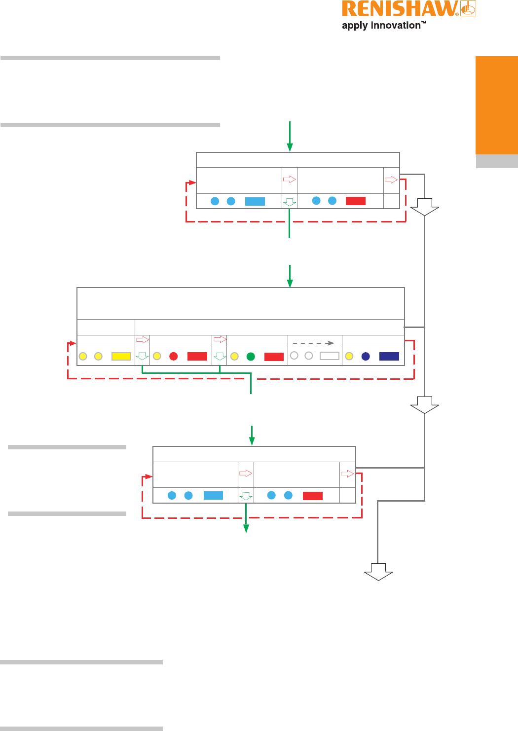
4.1
> 5 s
12
3
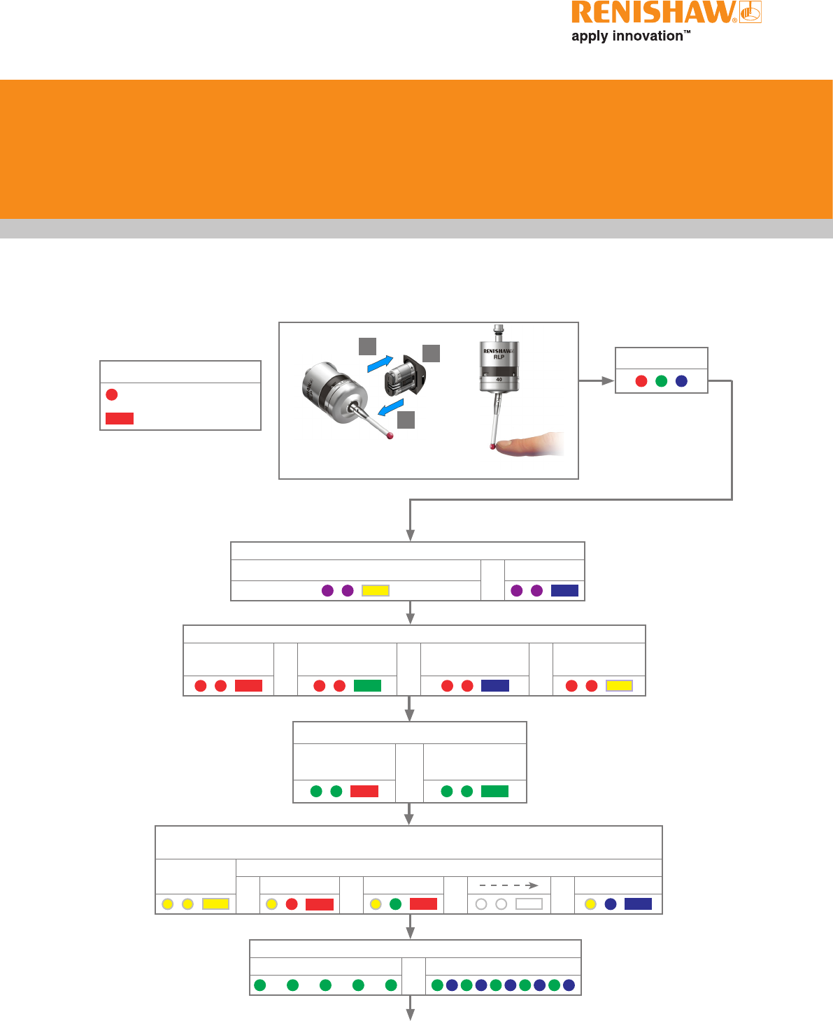
Key to the symbols
LED short flash
LED long flash
Switch on method
Radio on or Spin on
Switch off method
Radio off or
Spin off or
Short timeout
12 s or
Medium timeout
33 s or
Long timeout
134 s
LED check
Probe in standby mode
Battery status
Battery good or Battery low
Multiple probe mode (omitted for radio on)
see "Multiple probe mode settings" to view all 16 choices
Mode off Mode on
or Machine 1 or Machine 2 or or Machine 16
Reviewing the current probe
settings
Trigger Logic™
Enhanced trigger filter setting
Trigger filter
off or
Trigger filter
on
RLP40 installation guide
4.2
Trigger Logic™
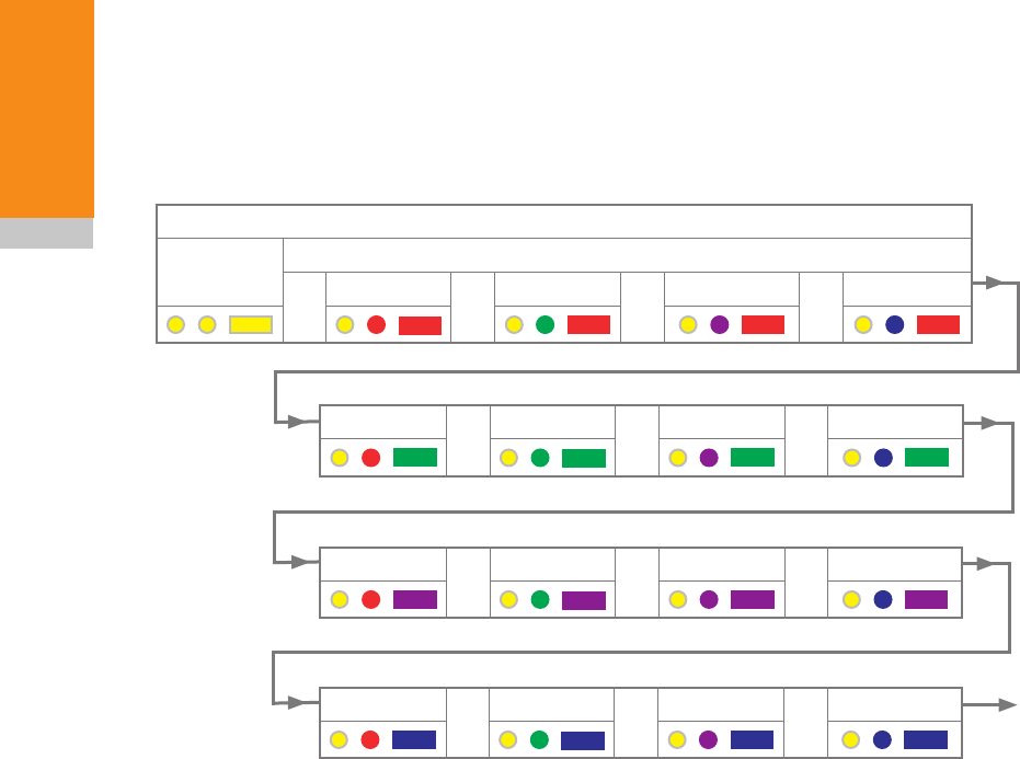
Multiple probe settings
Deflect the stylus for less than 4 seconds to
cycle to the next setting.
Multiple probe mode
Mode off Mode on
or Machine 1 or Machine 2 or Machine 3 or Machine 4
Machine 5 or Machine 6 or Machine 7 or Machine 8
Machine 9 or Machine 10 or Machine 11 or Machine 12
Machine 13 or Machine 14 or Machine 15 or Machine 16
Return to
"Mode off"

4.3
Trigger Logic™
Factory
settings
New
settings
Switch on method Radio on ✔
Spin on
Switch off method Radio or spin ✔
Short timeout (12 s)
Medium timeout (33 s)
Long timeout (134 s)
Enhanced trigger filter Trigger filter off ✔
Trigger filter on
Multiple probe mode Off (factory set) ✔
On (machine number) See "Multiple
probe settings"
RLP40 serial no ........................................
✔ tick
Probe settings record
This page is provided to note your probe's
settings. ✔ tick
X
RLP40 installation guide
4.4
Trigger Logic™
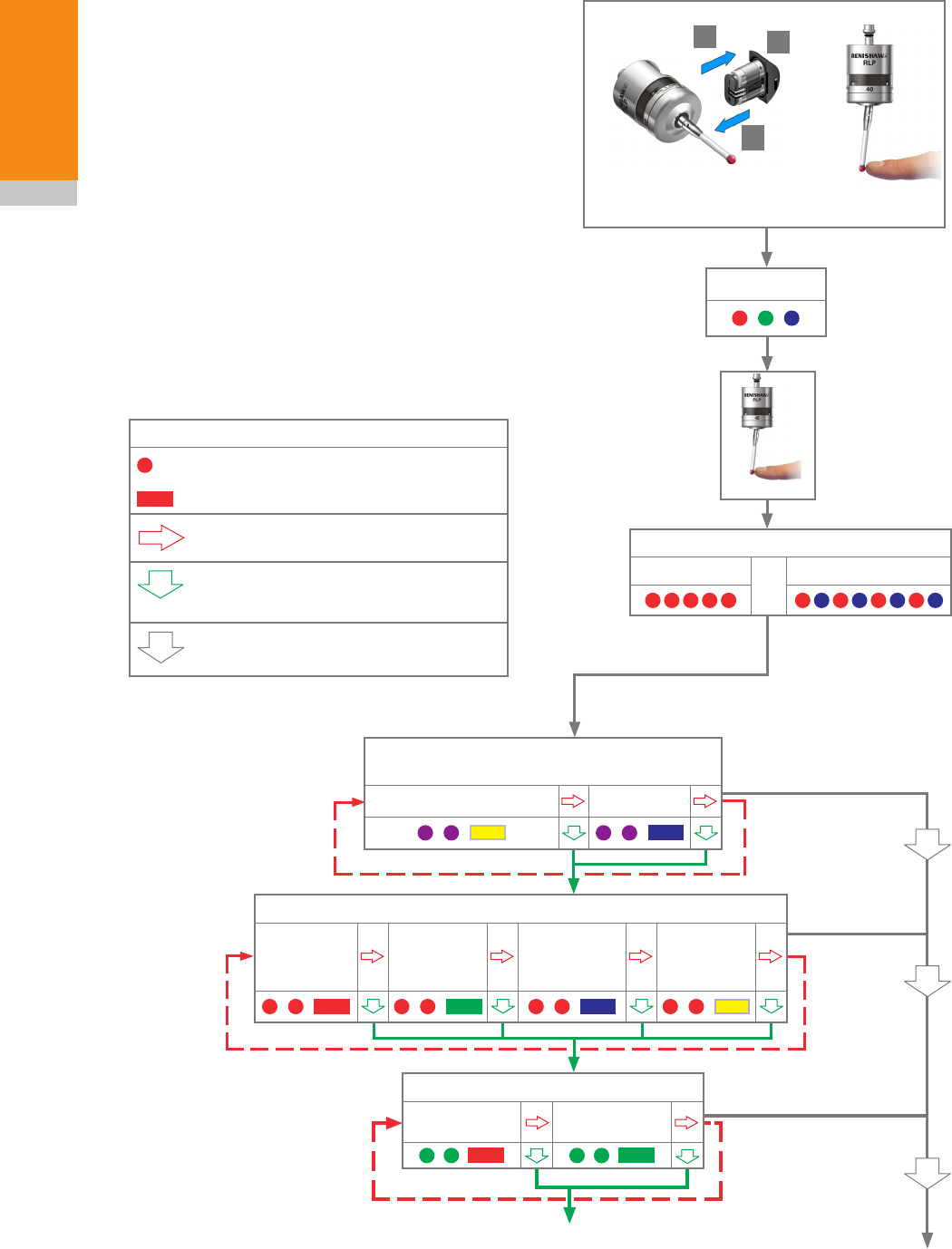
Switch on method
(omitted if multiple probe mode is selected)
Radio on Spin on
> 5 s
12
3
Key to the symbols
LED short flash
LED long flash
Deflect the stylus for less than 4 seconds
to move to the next menu option.
Deflect the stylus for more than
4 seconds to move to the next menu.
To exit, leave the stylus untouched for
more than 20 seconds.
LED check
Battery status
Battery good or Battery low
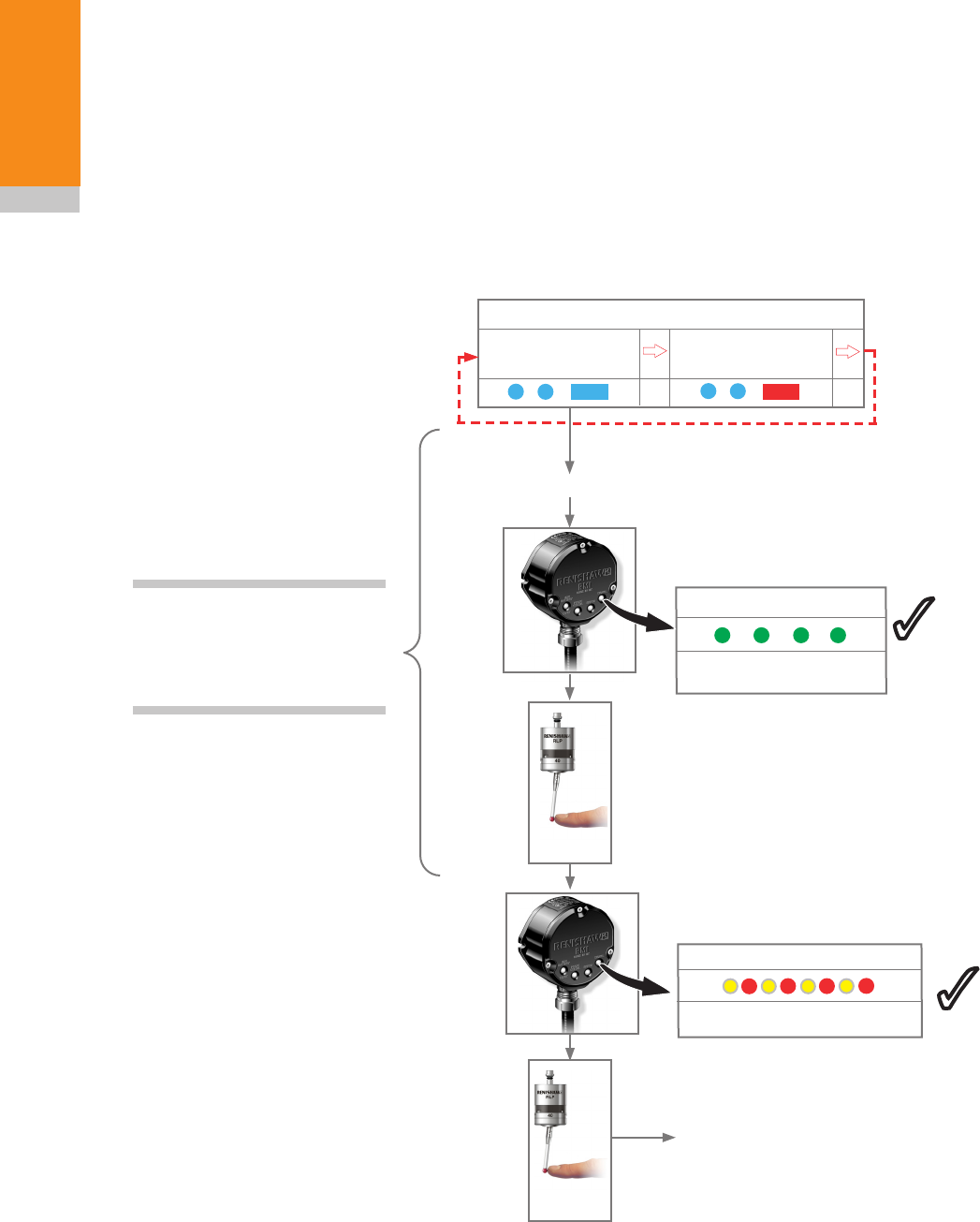
Changing the probe settings
Insert the batteries or, if they have already been
installed, remove them for five seconds and then
refit them.
Following the LED check, immediately deflect the
stylus and hold it deflected until five red flashes
have been observed (if the battery power is low
then each of the five red flashes will be followed
by a blue flash).
Keep the stylus deflected until the "Switch on
method" setting is displayed, then release the
stylus. The probe is now in configuration mode
and Trigger Logic™ is activated.
Switch off method
Radio off or
Spin off
Short
timeout
12 s
Medium
timeout
33 s
Long
timeout
134 s
3
continued on next page
Enhanced trigger filter
Off
0 s
On
10 ms
4.5
Trigger Logic™
NOTE: To partner an RLP40 with an RMI please
see "RLP40 – RMI partnership". Once acquisition
has been successful, the RLP40 will revert to
‘Acquisition mode off’.
NOTE: Further probes used
require the same multiple probe
mode setting, but do not need to be
partnered with the RMI.
Cease triggering here, unless the multiple probe mode is required
in which case deflect stylus > 4 seconds
NOTE: If no changes are made in multiple probe mode, then deflecting the stylus for more
than 4 seconds will return the probe settings to ‘To change switch-on method’
NOTE: To partner a
RLP40 with a RMI,
please see RLP40 - RMI
partnership.
Acquisition mode
off
Acquisition mode
Multiple probe mode (omitted for radio-on)
(See ‘Multiple probe mode settings’ to view all 16 choices)
Mode off Mode on
Return to “Change switch-on method”
Acquisition mode
on
Machine 1 Machine 2 Machine 16
Acquisition mode
off
Acquisition mode
Acquisition mode
on
New settings
complete
RLP40 installation guide
4.6
Trigger Logic™
RLP40 – RMI partnership
System set-up is achieved using Trigger Logic™
and powering the RMI. Partnering is only required
during initial system set-up. Further partnering
is only required if either the RLP40 or RMI is
changed, or a system is reconfigured for multiple
probes (multiple probe mode).
Partnering will not be lost by reconfiguring the
probe settings or when changing batteries, except
where multiple probe mode is selected. Partnering
can take place anywhere within the operating
envelope.
In configuration mode, configure the probe
settings as required until you reach the
"Acquisition mode" menu. Select "Acquisition
mode off".
Deflect the stylus to select 'Acquisition
mode on'.
Ensure this is done within 10 seconds
of the RMI signal LED flashing green.
SIGNAL LED
RMI in acquisition mode
3
3
The probe is in stand-by
and the system is ready
for use.
3
X
New partner RMP acquired
SIGNAL LED
> 20 s
Acquisition mode
off
Acquisition mode
Acquisition mode
on
NOTE: Once in ‘Acquisition
mode off’, ensure the next two
steps are completed within
20 seconds.
Switch on the RMI
< 4 s
X
3
4.7
Trigger Logic™
Operating mode
NOTE: Due to the nature of Lithium Thionyl Chloride batteries, if a 'low battery' LED sequence is
ignored or overlooked, then it is possible for the following sequence of events to occur:
1. When the probe is active, the batteries discharge until battery power becomes too low for the
probe to operate correctly.
2. The probe stops functioning, but then reactivates as the batteries recover sufficiently to provide the
probe with power.
3. The probe begins to run through the LED review sequence (see page 4.1).
4. Again, the batteries discharge and the probe ceases to function.
5. Again, the batteries recover sufficiently to provide the probe with power, and the sequence is
repeated.
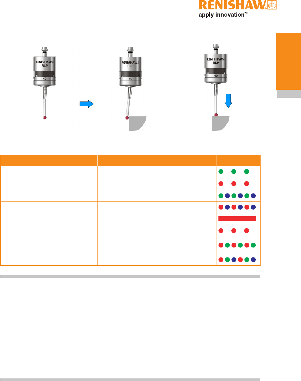
LED colour Probe status Graphic hint
Flashing green Probe seated in operating mode
Flashing red Probe triggered in operating mode
Flashing green and blue Probe seated in operating mode – low battery
Flashing red and blue Probe triggered in operating mode – low battery
Constant red Battery dead
Flashing red
or
Flashing red and green
or
Sequence when batteries are inserted
Unsuitable battery
LEDs
flashing
green
LEDs
flashing
red
LEDs
flashing
red
X/Y Z
Probe status LEDs

RLP40 installation guide
4.8
Trigger Logic™
This page left intentionally blank
5.1
Maintenance
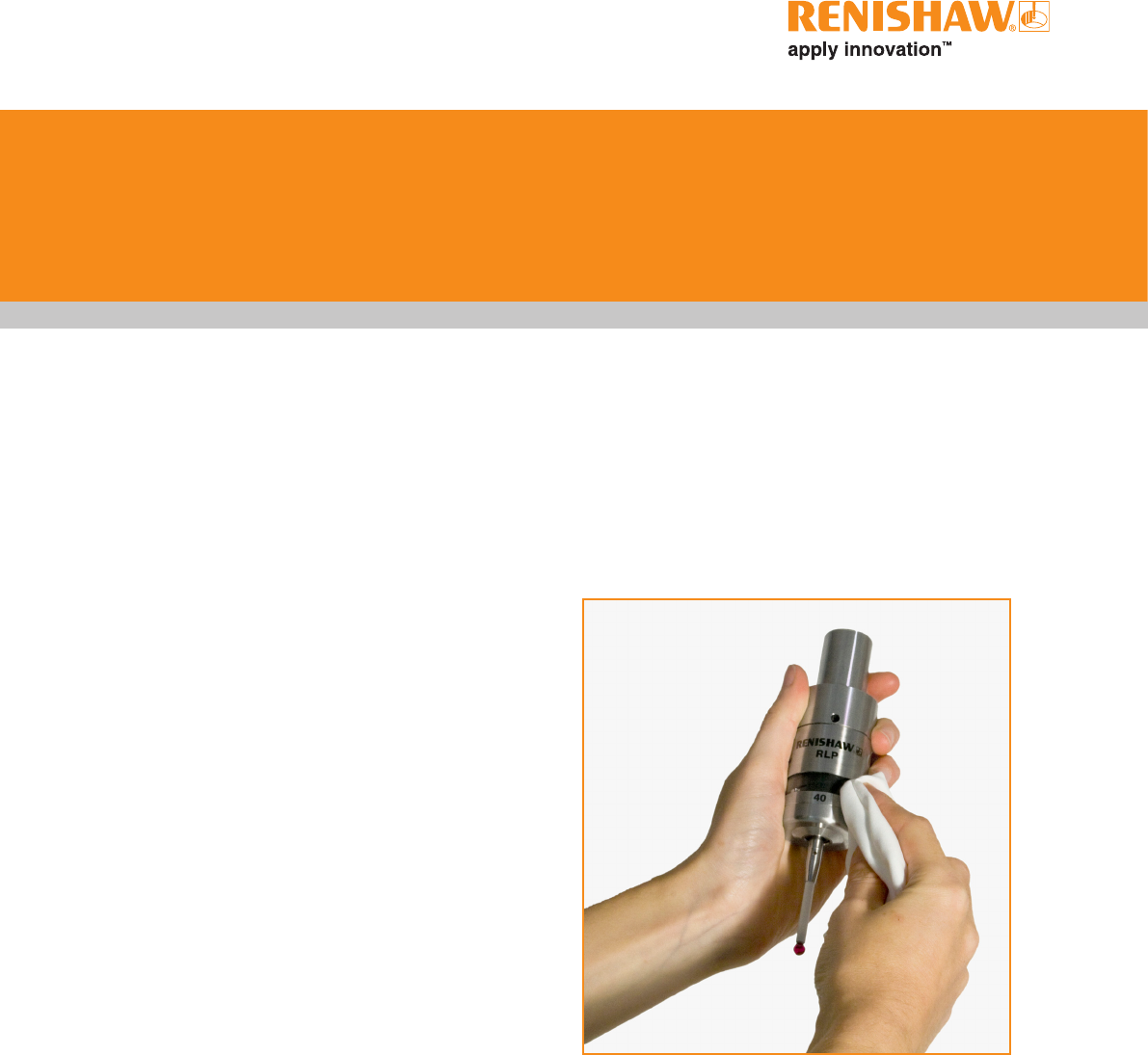
Cleaning the probe
Wipe the window of the probe with a clean cloth
to remove machining residue. This should be
done on a regular basis to maintain optimum
transmission.
Maintenance
You may undertake the maintenance routines
described in these instructions.
Further dismantling and repair of Renishaw
equipment is a highly specialised operation,
which must be carried out at authorised
Renishaw Service Centres.
Equipment requiring repair, overhaul or attention
under warranty should be returned to your
supplier.
RLP40 installation guide
5.2
Maintenance
Changing the batteries
1
2
!
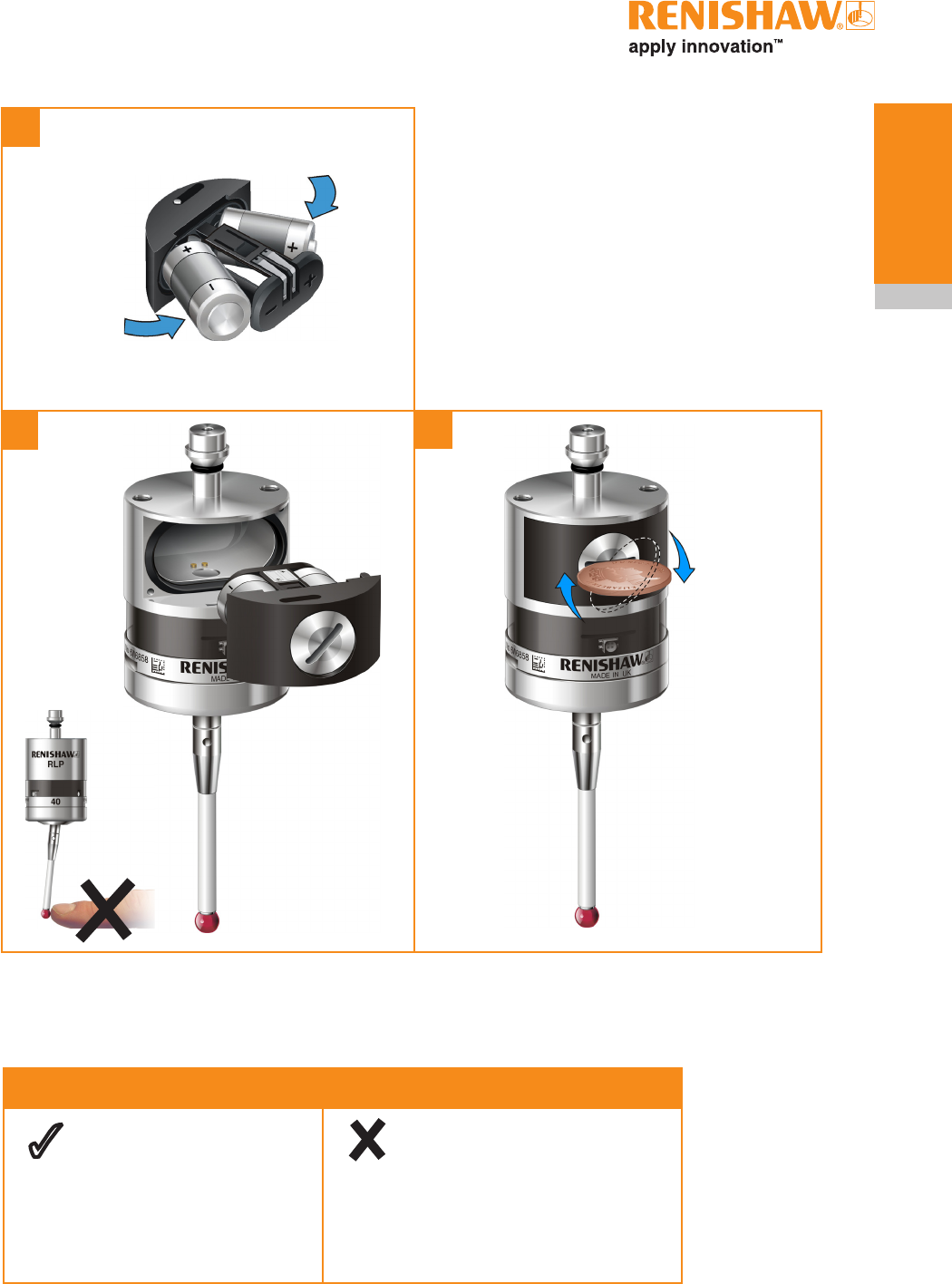
CAUTIONS:
Do not leave exhausted batteries in probe.
When changing batteries, do not allow coolant or
debris to enter the battery compartment.
When changing batteries, check that the battery
polarity is correct.
Take care to avoid damaging the battery cassette
gasket.
Only use specified batteries (page 5.3).
NOTES:
After removing the old batteries, wait more than
5 seconds before inserting the new batteries.
Do not mix new and used batteries or battery
types, as this will result in reduced life and
damage to the batteries.
Always ensure that the cassette gasket and
mating surfaces are clean and free from dirt
before reassembly.
If dead batteries are inadvertently inserted into
the probe, the LEDs will remain a constant red.
CAUTIONS:
Please dispose of exhausted batteries in
accordance with local regulations.
Never dispose of batteries in a fire.
!
5.3
Maintenance
3
45
½ AA Lithium Thionyl Chloride (3.6 V) x 2
Ecocel: EB1426
Saft: LS 14250C,
LS 14250
Tadiran: SL-750
Xeno: XL-050F
Dubilier: SB-AA02
Maxell: ER3S
Sanyo: CR 14250SE
Tadiran: SL-350, SL-550
TL-4902 TL-5902,
TL-2150, TL-5101
Varta: CR 1/2 AA
3
Battery type
RLP40 installation guide
5.4
Maintenance
RLP40 eyelid
The RLP40 is fitted with a metal eyelid that
protects the internal components of the probe
from hot chip and coolant environment. Dirt may
accumulate in the cavity underneath the metal
eyelid seal.
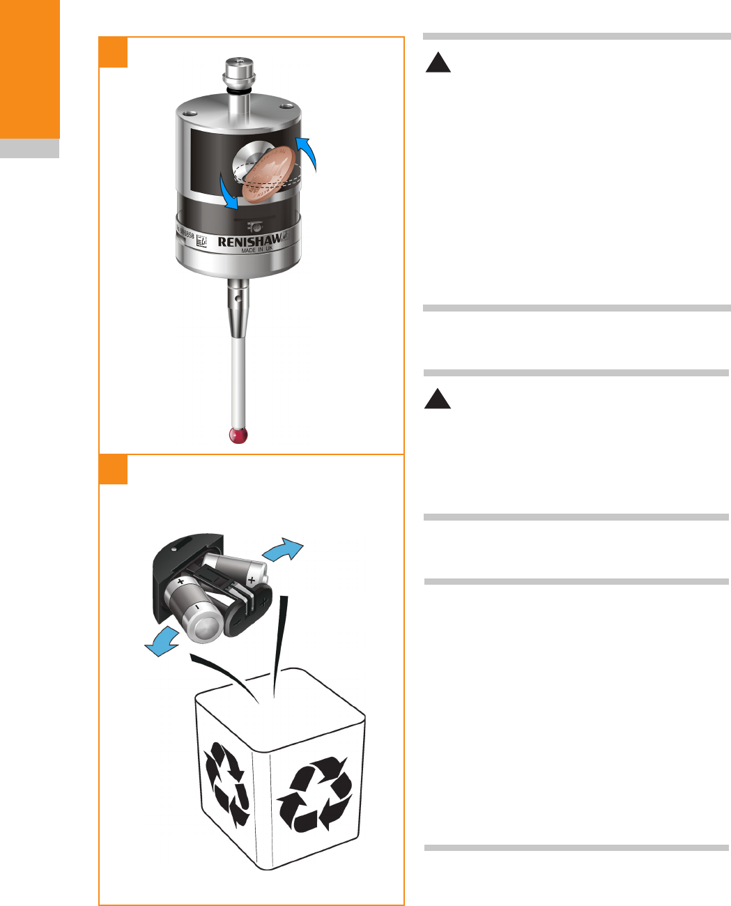
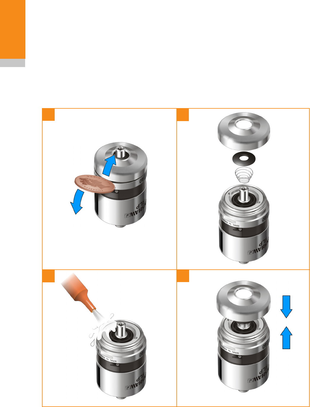
To remove this dirt, once a month, remove the
front cap (using a coin or flat blade screwdriver)
and then remove all of the residue with a low-
pressure jet of coolant.
A
1
3
2
4
Do not use a sharp tool or a degreasing agent.
The cleaning interval may be extended or
reduced, depending on the rate dirt accumulates.
If the inner diaphragm is damaged, return the
probe to your supplier for repair.
Re-assembling the probe
DO NOT use the probe with the cap removed.
Check that the probe is firmly secured in its
mounting.
Apply coin or flat
blade screwdriver
to both sides to
sequentially lever
front cap from probe
body

6.1
Symptom Cause Action
Probe fails to power up
(no LEDs illuminated or
fails to indicate current
probe settings).
Dead batteries. Change batteries.
Wrong batteries. Change batteries.
Batteries inserted incorrectly. Check battery insertion/polarity.
Batteries removed for too short a
time and probe has not reset.
Remove batteries for a minimum
of 5 seconds.
Probe fails to switch on. Dead batteries. Change batteries.
Batteries inserted incorrectly. Check battery insertion/polarity.
Probe out of range. Check position of RMI, see
operating envelope.
No RMI 'start/stop' signal (radio
on mode only).
Check RMI for green start LED.
Incorrect spin speed (spin switch
on only).
Check spin speed and duration.
Incorrect switch on method
configured.
Check configuration and alter as
required.
Incorrect multiple probe mode
setting configured.
Check configuration and alter as
required.
RLP40 in hibernation mode
(radio on mode only).
Ensure probe is in range and wait
up to 30 seconds, then resend
switch on signal.
Check position of RMI, see
operating envelope.
Fault finding

RLP40 installation guide
6.2
Fault finding
Symptom Cause Action
Machine stops
unexpectedly during a
probing cycle.
Radio link failure/RLP40 out of
range.
Check interface/receiver and
remove obstruction.
RMI receiver/machine fault. Refer to receiver/machine user’s
guide.
Dead batteries. Change batteries.
Probe unable to find target
surface.
Check that part is correctly
positioned and that stylus has not
broken.
Stylus not given sufficient time to
settle from a rapid deceleration.
Add a short dwell before the
probing move (length of dwell will
depend on stylus length and rate
of deceleration). Maximum dwell is
one second.
Probe crashes. Workpiece obstructing probe path. Review probing software.
Probe length offset missing Review probing software.

6.3
Fault finding
Symptom Cause Action
Poor probe repeatability
and/or accuracy.
Debris on part or stylus. Clean part and stylus.
Poor tool change repeatability. Redatum probe after each tool
change.
Loose probe mounting on shank
or loose stylus.
Check and tighten as appropriate.
Calibration out of date and/or
incorrect offsets.
Review probing software.
Calibration and probing speeds
not the same.
Review probing software.
Calibration feature has moved. Correct position.
Measurement occurs as stylus
leaves surface.
Review probing software.
Measurement occurs within
the machine’s acceleration and
deceleration zone.
Review probing software and
probe filter settings.
Probing speed too high or too
slow.
Perform simple repeatability trials
at various speeds.
Temperature variation causes
machine and workpiece
movement.
Minimise temperature changes.
Machine tool faulty. Perform health checks on
machine tool.
RLP40 status LEDs do
not correspond to RMI
status LEDs.
Radio link failure – RLP40 out of
RMI range.
Check position of RMI, see
operating envelope.
RLP40 has been enclosed/
shielded by metal.
Remove from obstruction.
RLP40 and RMI are not
partnered.
Partner RLP40 and RMI.

RLP40 installation guide
6.4
Fault finding
Symptom Cause Action
RMI error LED lit during
probing cycle.
Probe not switched on or probe
timed out.
Change setting. Review turn off
method.
Probe out of range. Check position of RMI, see
operating envelope.
RMI low battery LED lit. Low batteries. Change batteries soon.
Reduced range. Local radio interference. Identify and remove.
Probe fails to switch off. Incorrect switch off method
configured.
Check configuration and alter as
required.
No RMI 'start/stop' signal (radio
on mode only).
Check RMI for green start LED.
Probe in timeout mode and
placed in tool magazine and is
being triggered by movement.
Use shorter timeout setting or use
different switch off mode.
Incorrect spin speed (spin turn on
only).
Check spin speed.
Probe goes into Trigger
Logic™ configuration
mode and cannot be
reset.
Probe was triggered when
batteries were inserted.
Do not touch the stylus or stylus
mounting face during battery
insertion.
7.1
Type Part number Description
RLP40 A-5627-0001 RLP40 probe with batteries, tool kit and quick-start guide
(factory set to radio on/radio off, trigger filter off).
Battery P-BT03-0007 1/2 AA Lithium Thionyl Chloride (LTC) batteries pack of two.
Stylus A-5000-3709 PS3-1C ceramic stylus 50 mm long with Ø6 mm ball.
Weak link kit A-2085-0068 Weak link (Part no. M-2085-0069 x 2) and 5 mm AF spanner.
Tool kit A-4038-0304 Probe tool kit comprising Ø1.98 mm stylus tool, 2.0 mm AF
hexagon key, 2.5 mm AF hexagon key (x 2), 4.0 mm AF
hexagon key (x 2) and shank grub screw (x 2).
Service kit A-5625-0005 RLP40 eyelid service kit.
Battery cassette A-4071-1166 RLP40 battery cassette assembly.
Cassette seal A-4038-0301 Battery cassette housing seal.
RMI A-4113-0050 RMI – side exit – with 15 m (49.2 ft) cable, tool kit and user's
guide.
Mounting bracket A-2033-0830 Mounting bracket with fixing screws, washers and nuts.
Stylus tool M-5000-3707 Tool for tightening/releasing styli.
Publications. These can be downloaded from our web site at www.renishaw.com
RLP40 A-5627-8501 Quick-start guide: for rapid set-up of the RLP40 probe,
includes CD with installation guide.
Styli H-1000-3200 Technical specification: Styli and accessories.
Software features H-2000-2298 Data sheet: Probe software for machine tools – illustrated
features.
Software list H-2000-2298 Data sheet: Probe software for machine tools – list of
programs.
RMI H-2000-5220 Installation and user's guide: RMI – radio machine interface.
Parts list

RLP40 installation guide
7.2
Parts list
This page left intentionally blank

Renishaw plc
New Mills, Wotton-under-Edge,
Gloucestershire, GL12 8JR
United Kingdom
T +44 (0)1453 524524
F +44 (0)1453 524901
E uk@renishaw.com
www.renishaw.com
For worldwide contact details,
please visit our main website at
www.renishaw.com/contact
*H-5627-8504-01*
© 2010 Renishaw plc Issued January 2010 Part no. H-5627-8504-01-A