Rentokil Initial 1927 plc GSD-500349 LongReach Radio Module User Manual Title page image
Rentokil Initial 1927 plc LongReach Radio Module Title page image
Contents
Users Manual - MMT

Adam O’Callaghan/JMc
Multi Mouse Trap Connect
(MMT) User Guide
16-04-18 –GSD-100694 Version 1.0

2
MMT - Overview
•Retrofittable to TinCat models from Victor and JT Eaton.
•Retrofittable to Little Pete models from JT Eaton
•Battery Powered
•Reports activations directly to PestNet Online
•Based on RI Connect LongReach 868/915MHz Technology
3
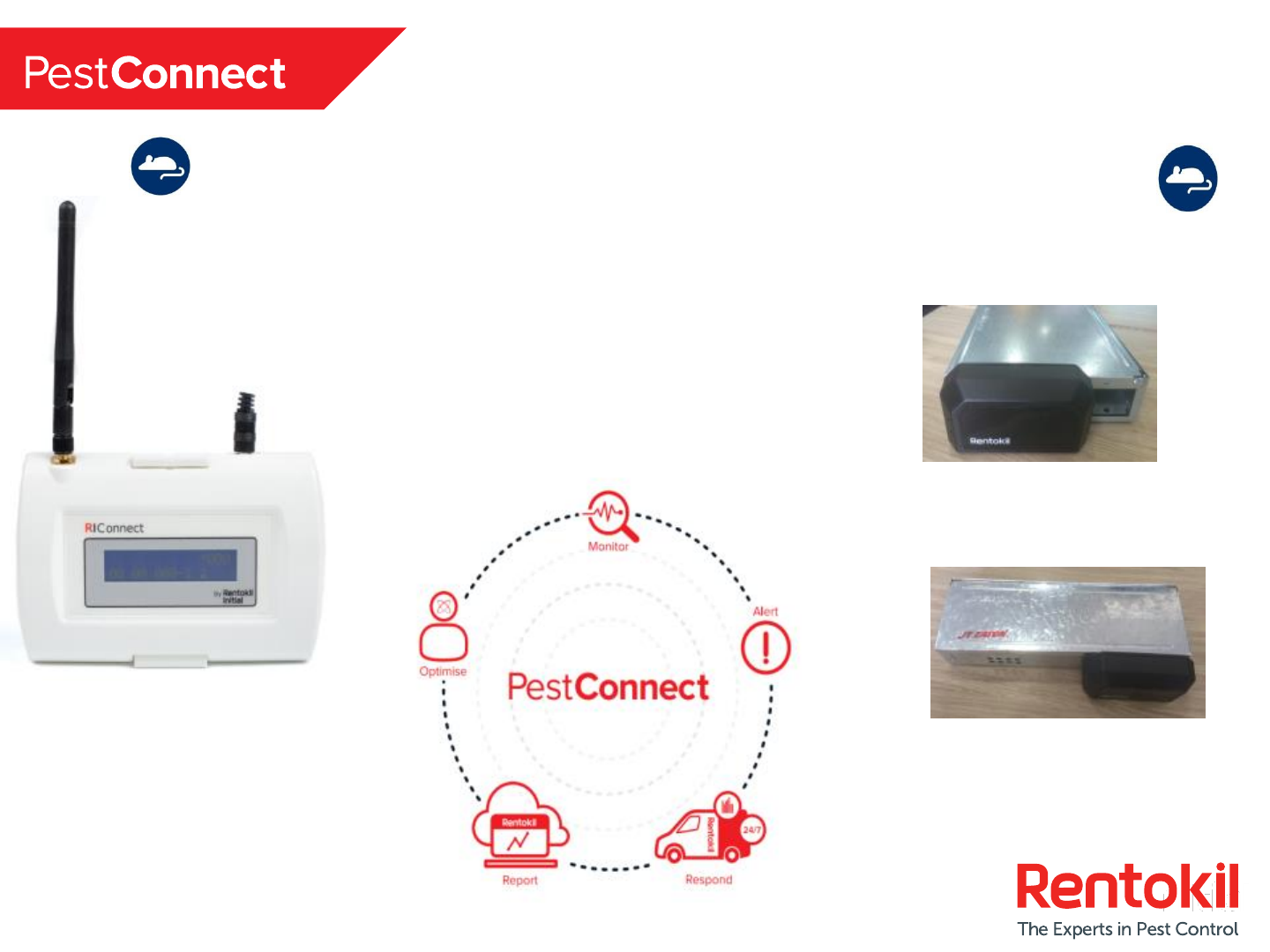
Introduction to the PestConnect
System
MMT Connect
Units
Control Panel

4
MMT Technical Details
Battery Supply
2 x AA Cell Alkaline Batteries
Dimensions 112mm x 38mm x 60mm
Material 20% Glass Filled PC
Weight 173g
Operating Temperature -20 to +50 Celcius
Mounting JT Eaton & Victor TinCat’s
JT Eaton Little Pete
Standards/Certifications FCC
IP Rating IP67
5
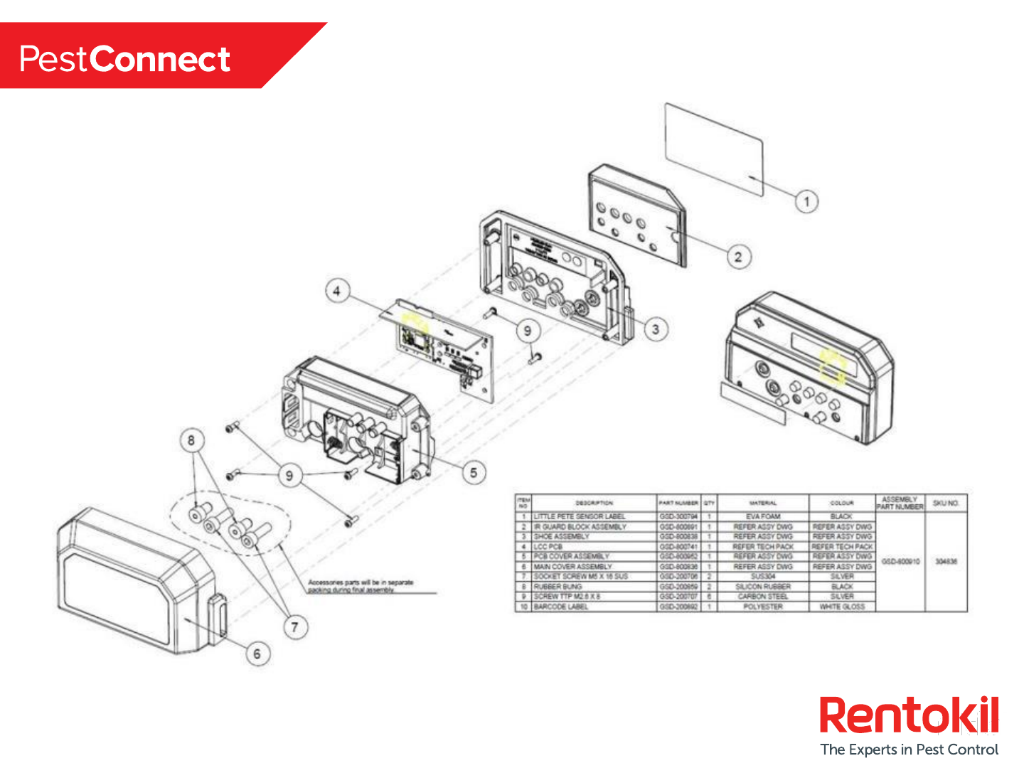
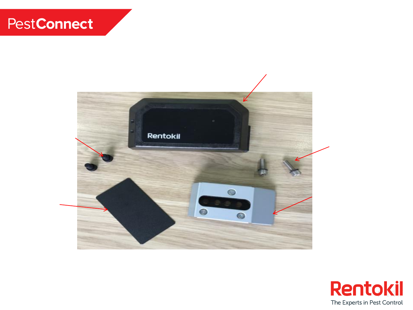
Product Exploded View
6
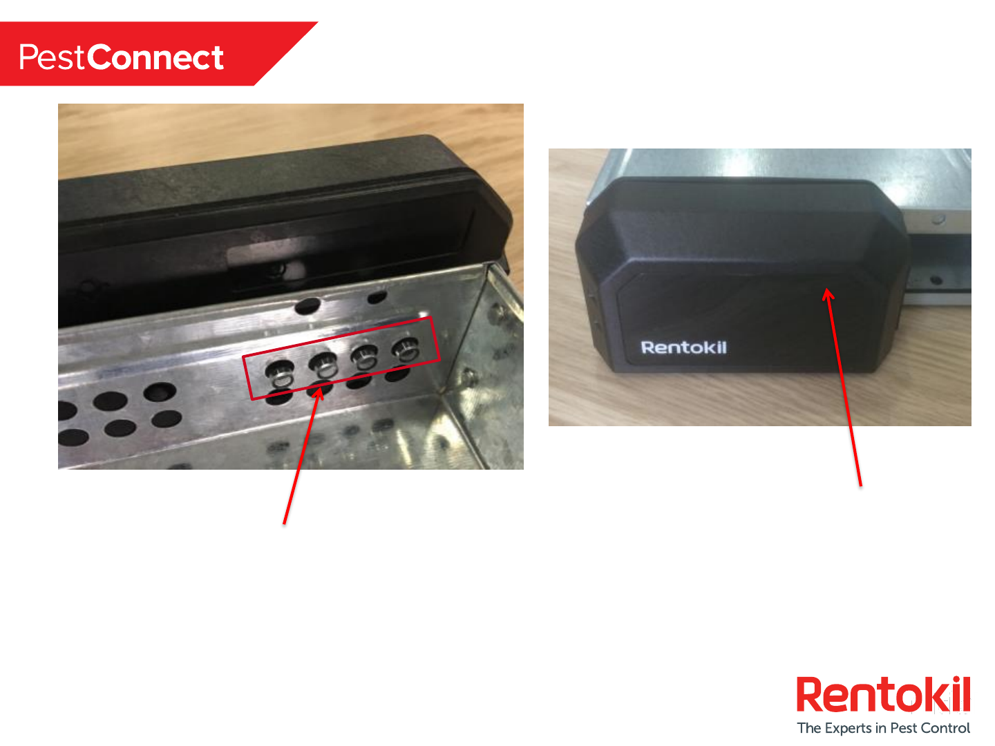
MMT Sensor –Key Hardware Features 1 / 2
Infra Red light Sensors scan
inside the trap, monitoring for
rodent activity.
2 x Hidden until lit LED’s show
the technician the status of the trap
7
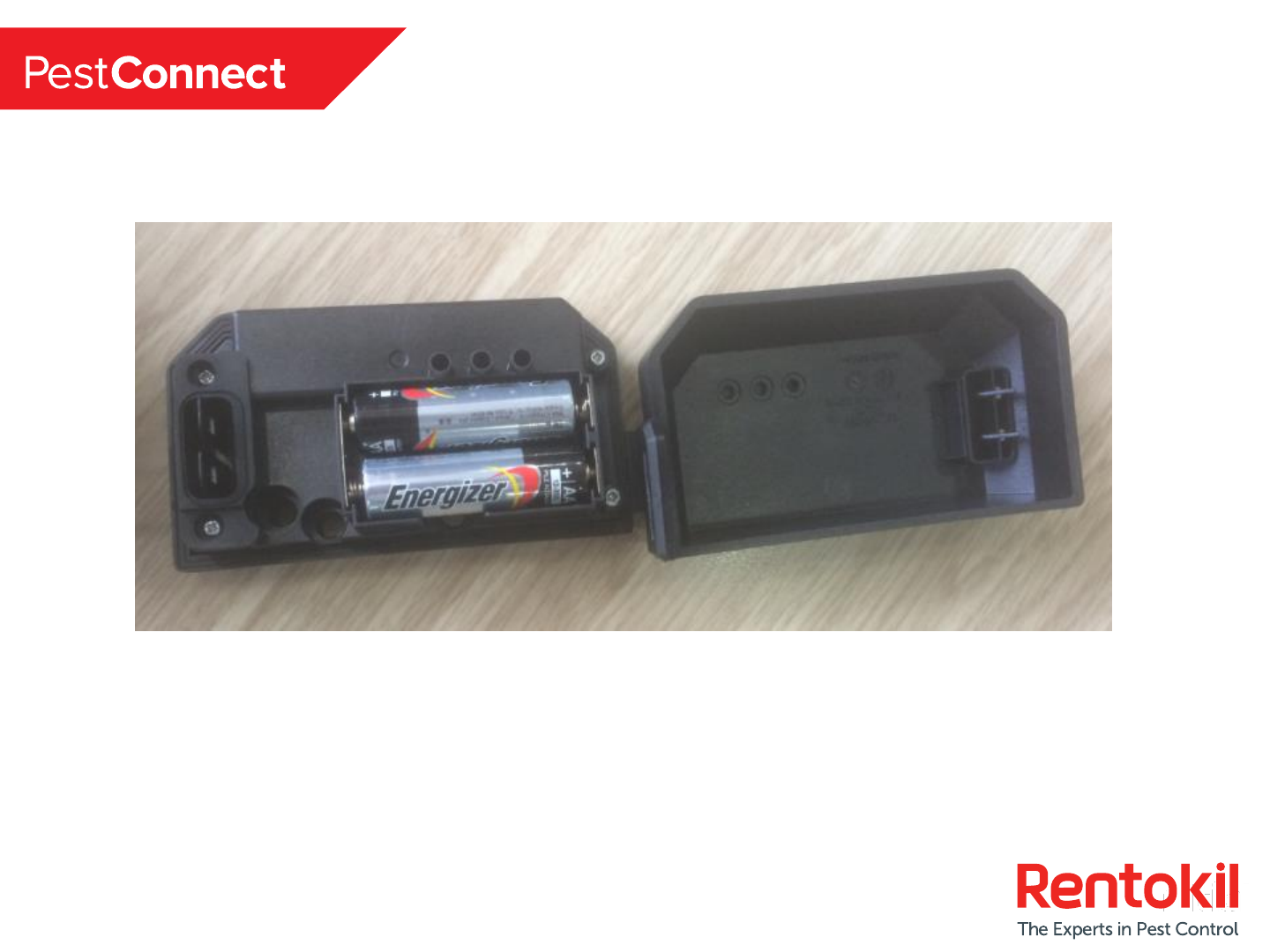
MMT Sensor –Key Hardware Features 2 / 2
Battery compartment –housing 2 x AA Alkaline Batteries
8
In box components
Live Catch Connect Sensor
Anti reflection
label
Rubber Bungs (x2) Fixing Bolts (x2)
NB: For each box of 10 x MMT sensors 1x Pest Key and 2x
allen keys will be provided
Trap Fixing Bracket
9
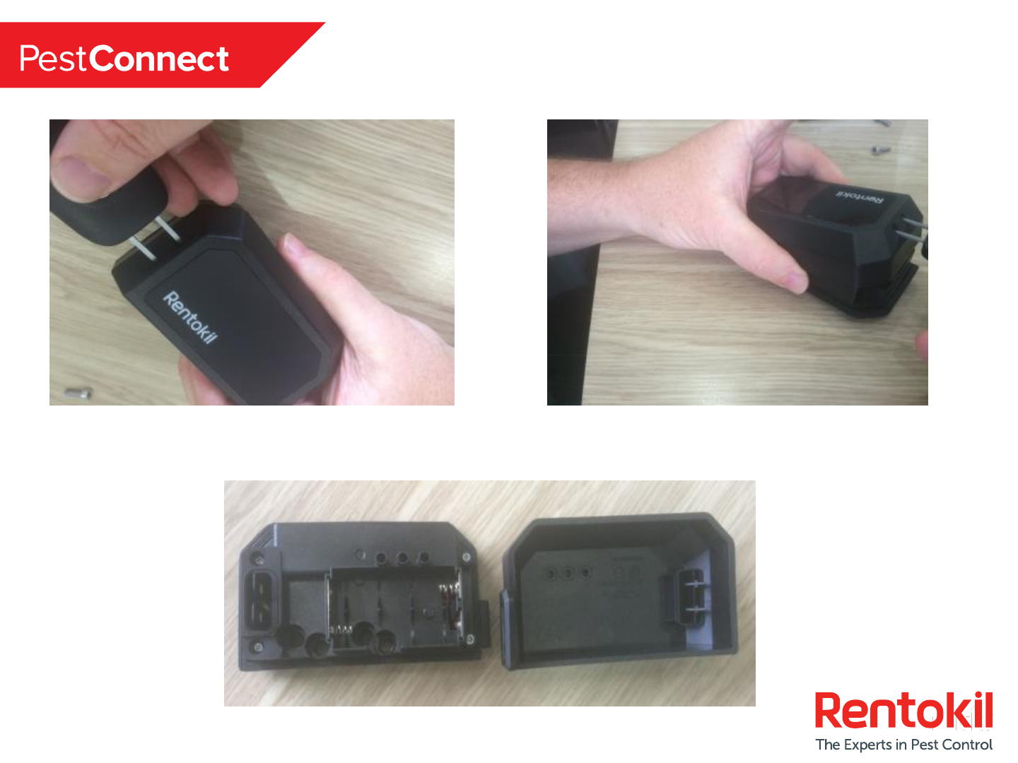
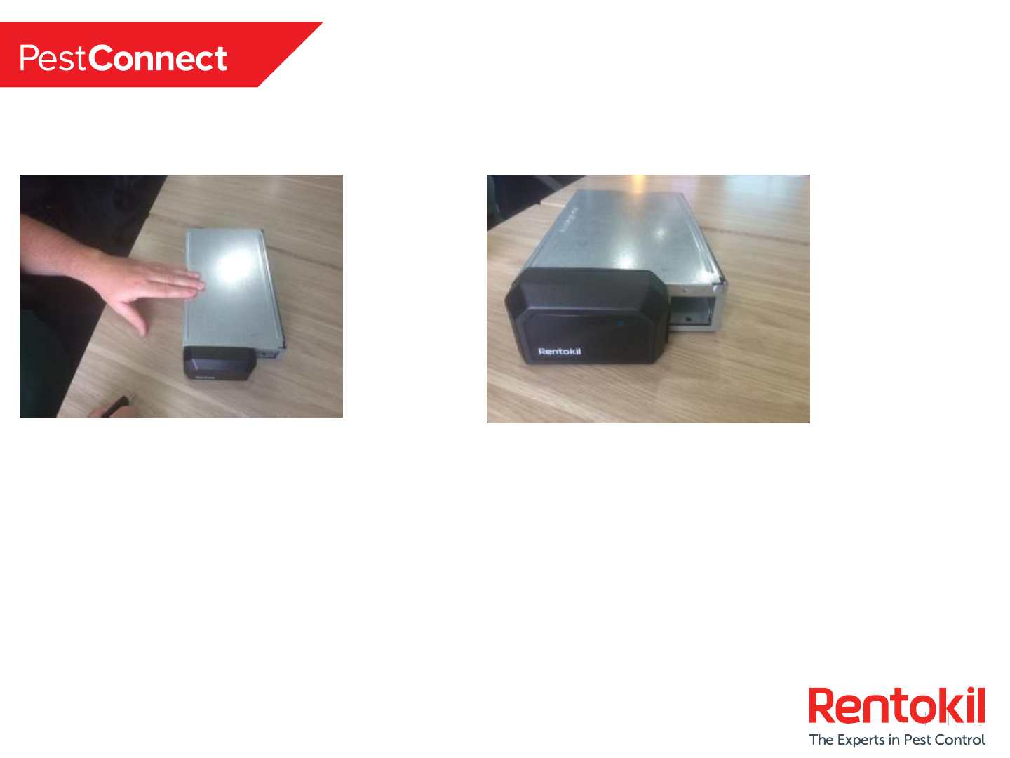
Install Step 1 –Remove Front Cover using
Pest Key
Step 1 Step 2
Step 3
10
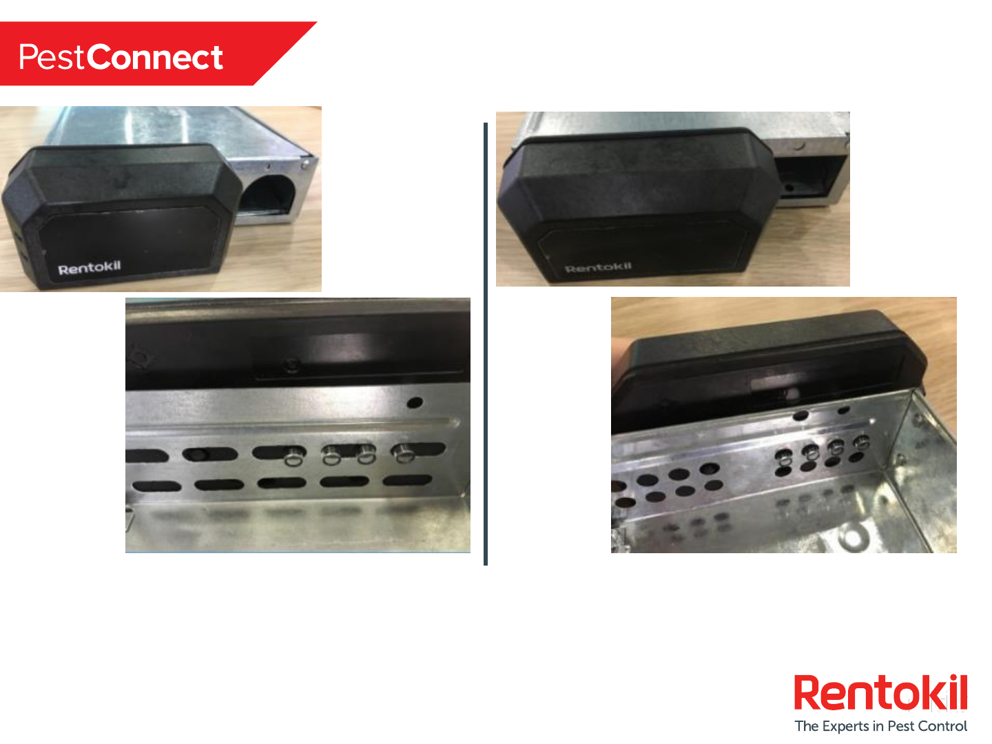
Install Step 3 –Align Infra Red Sensors
Lenses to the openings in the trap
Infra red sensor lenses align with the traps on the RHS as shown above for Tin Cat.
NB: For Little Pete there is only one alignment option.
Victor Tin Cat JT Eaton Tin Cat
11
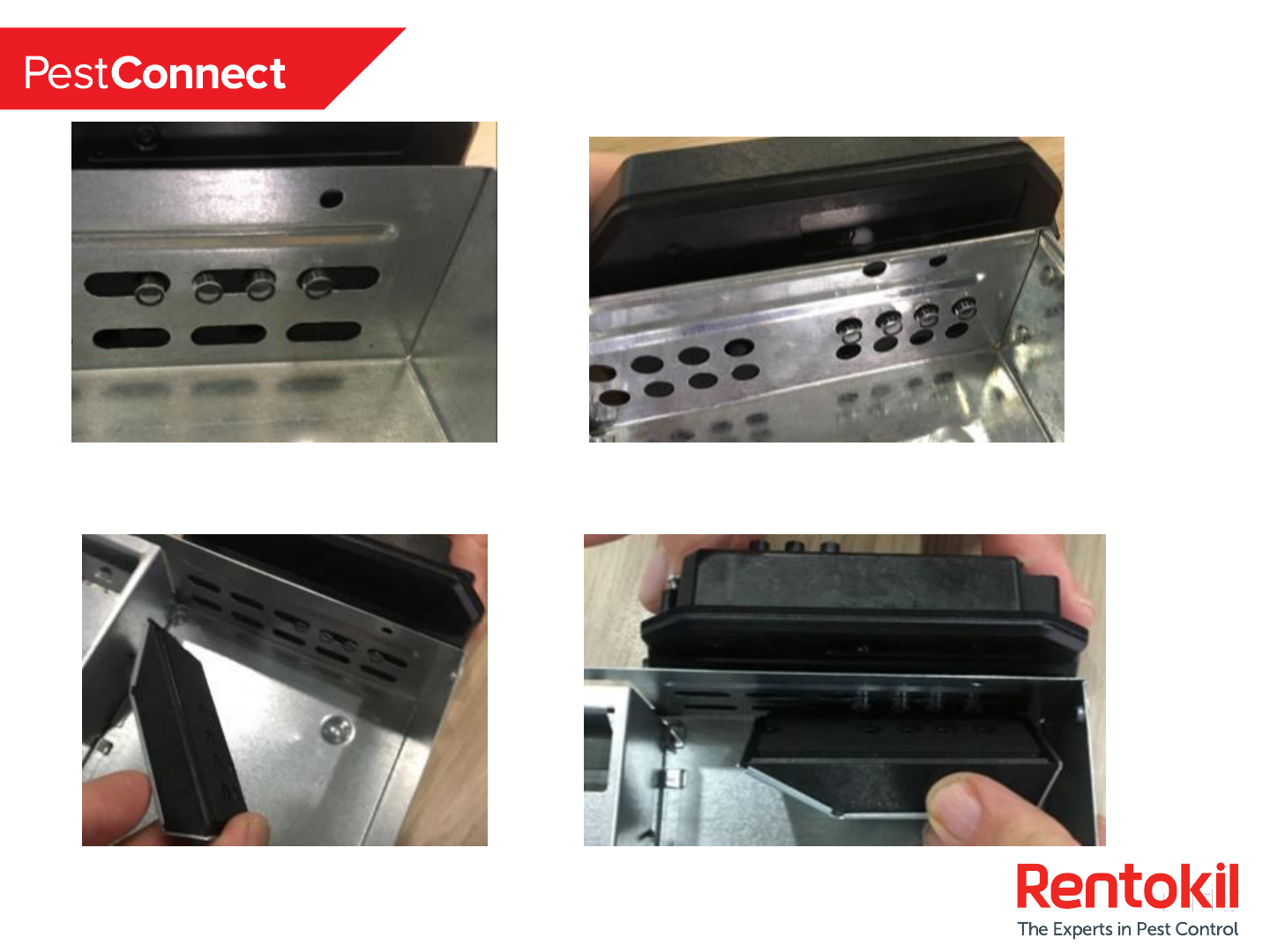
Install Step 4 –Bolt Sensor to trap
Position LED Lenses to Trap Holes as shown above.
Take the Trap Fixing Bracket and
Orientate as shown above. Place the Trap Fixing Bracket over the LED Lenses
and hold together for bolting (see next page).
JT Eaton Tin Cat
Victor Tin Cat
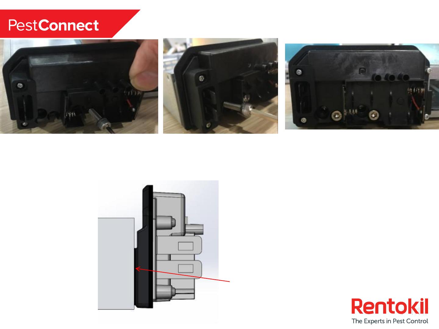
12
Install Step 4 –Bolt Sensor to trap
Bolts Fitted
Tighten bolts using allen key provided or any suitable 8mm allen key.
Please note that the above bolt configuration is for Victor Tin Cat.
Use the other set of holes for bolting the JT Eaton Tin Cat.
Tighten bolts & ensure sensor is securely fitted to
the trap. The Sensor should be parallel to trap as
shown left.
Second BoltFirst Bolt
13
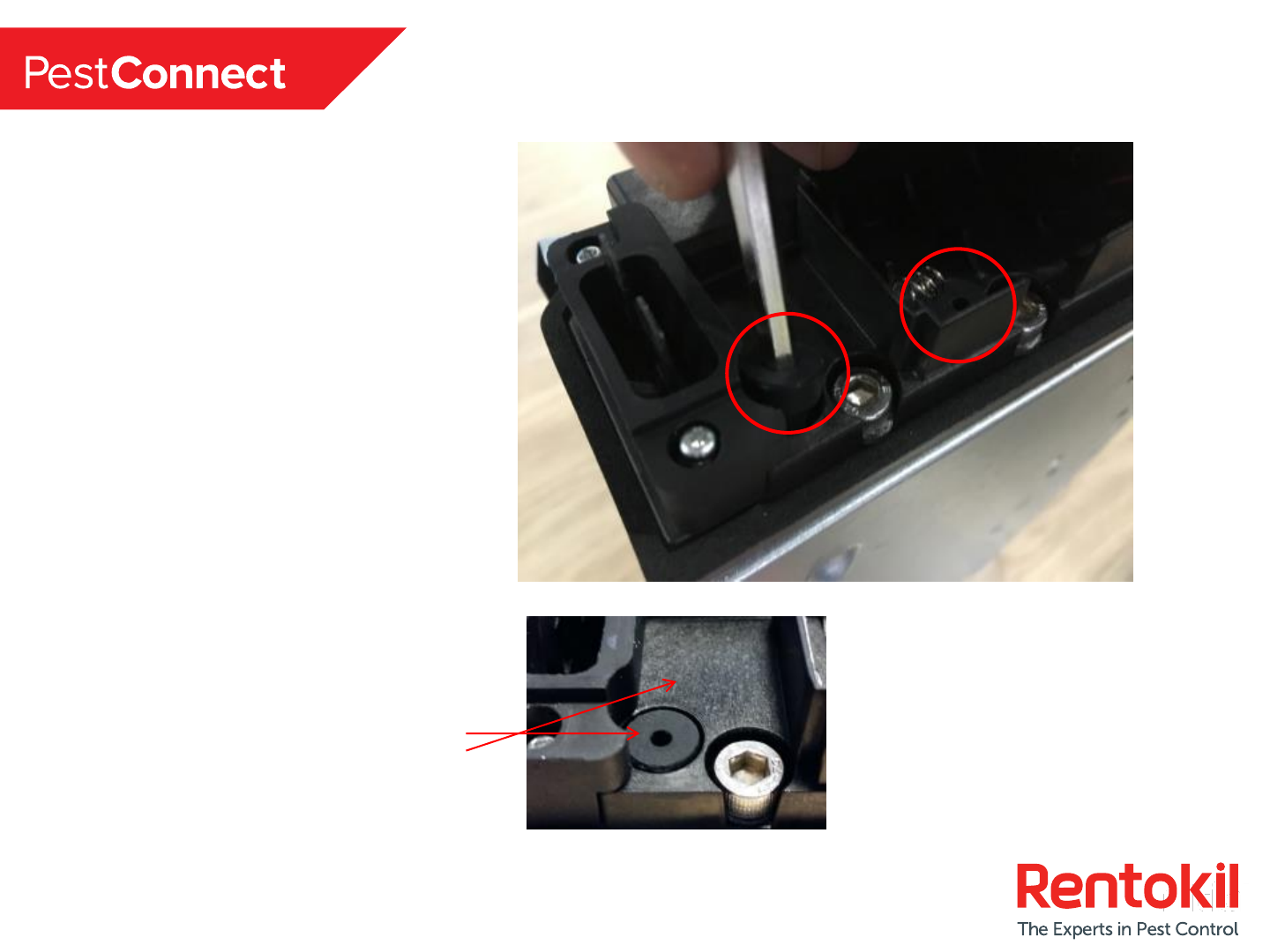
Install Step 5 –Fit Rubber Bungs
Fit the two supplied rubber bungs to
the sensor using the allen key
supplied. This is required to close and
seal the two unused holes to prevent
water ingress (mandatory).
Please note that this bolt configuration
is for Victor Tin Cat.
Use the other set of holes for rubber
bungs sealing the JT Eaton Tin Cat.
Push the bung firmly down to fully
insert as shown. The top of the
rubber bung must be level or sub
flush to the top surface in both
positions.
14
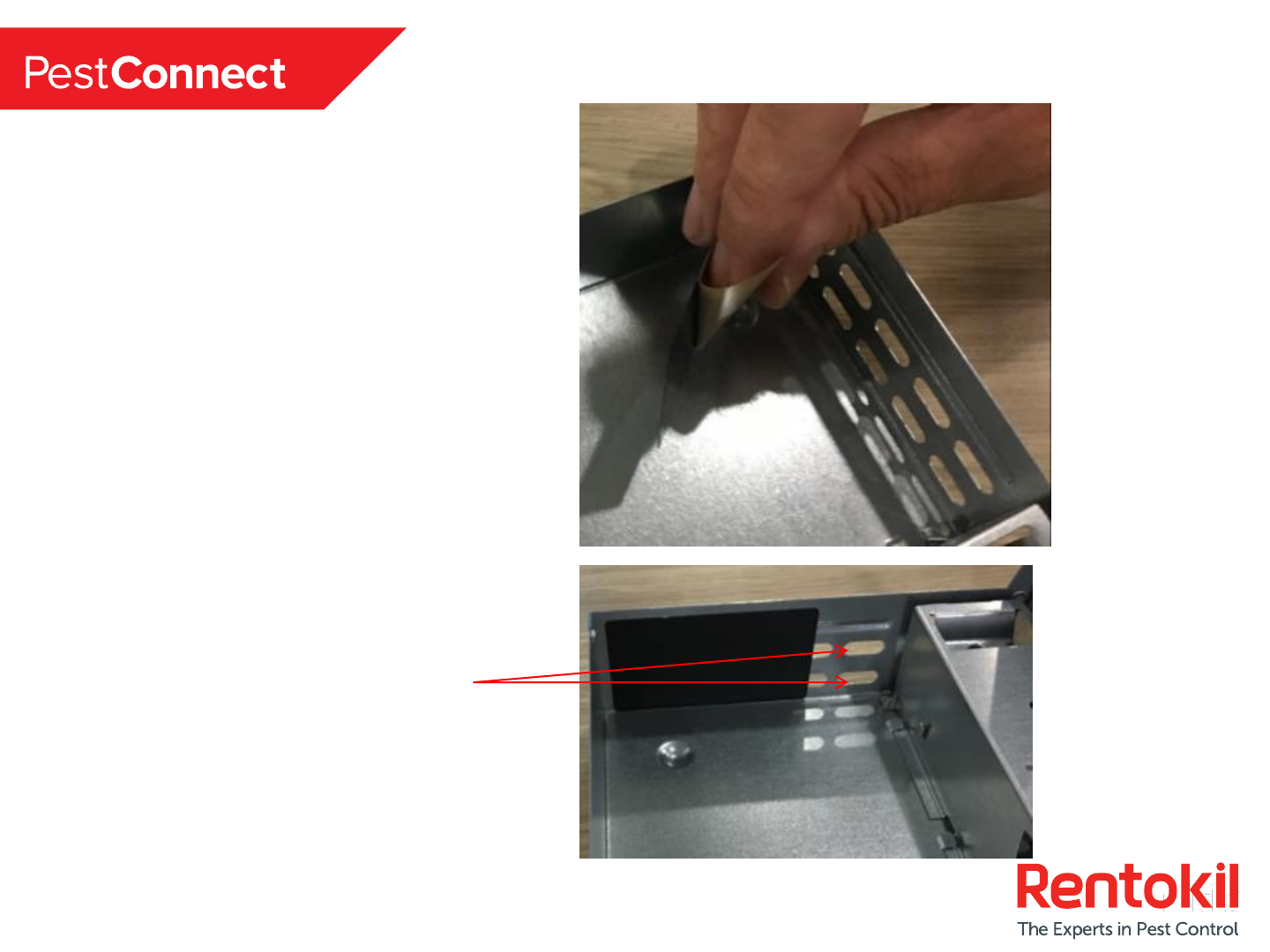
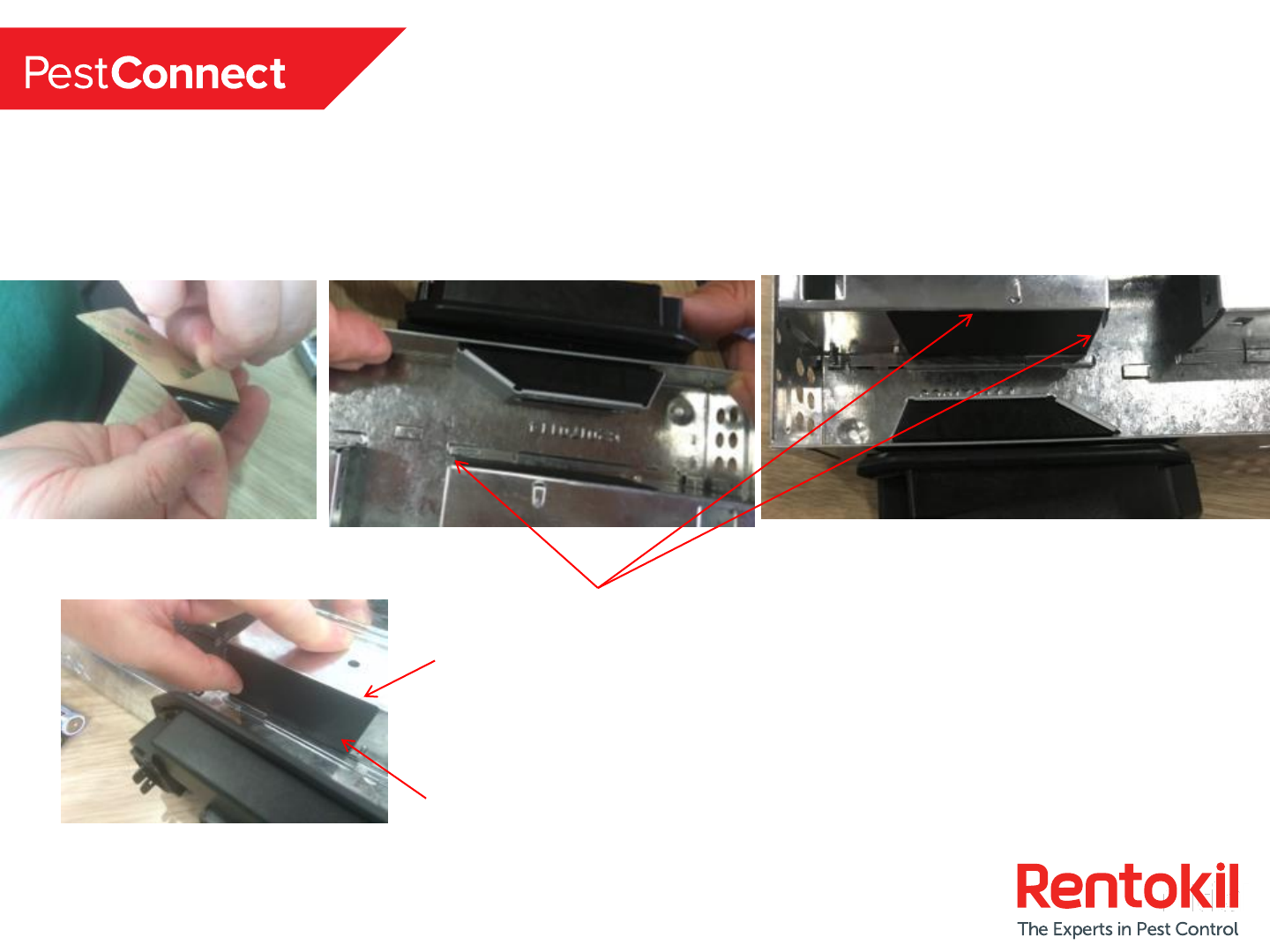
Install Step 6 –Fit Label to Trap
Fit the supplied black label inside the
Victor/JT Eaton at the opposite end of
the trap from the sensor (mandatory).
Peel back the release liner to reveal
the adhesive and adhere accordingly.
Please note that this configuration
(Picture left) is Victor Tin Cat.
Identical required for JT Eaton Tin
Cat.
Ensure that the are two holes open.
15
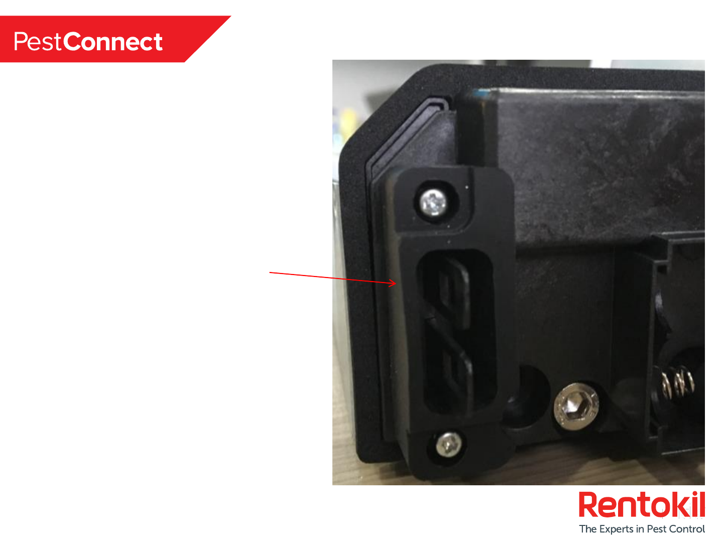
Install Step 7 –Fit Rubber Sealing Boot.
Orientate and Push Fit the supplied
Black Rubber Sealing Boot to the
Sensor in position shown left
(mandatory).
16
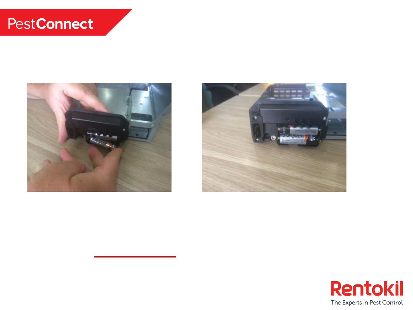
Install Step 8 –Install Batteries
Note 1: Only use suitable AA Alkaline Batteries
Note 2: The trap lid MUST BE CLOSED during the battery installation to avoid
false triggers during the final setup stage, pictures for reference only.
17
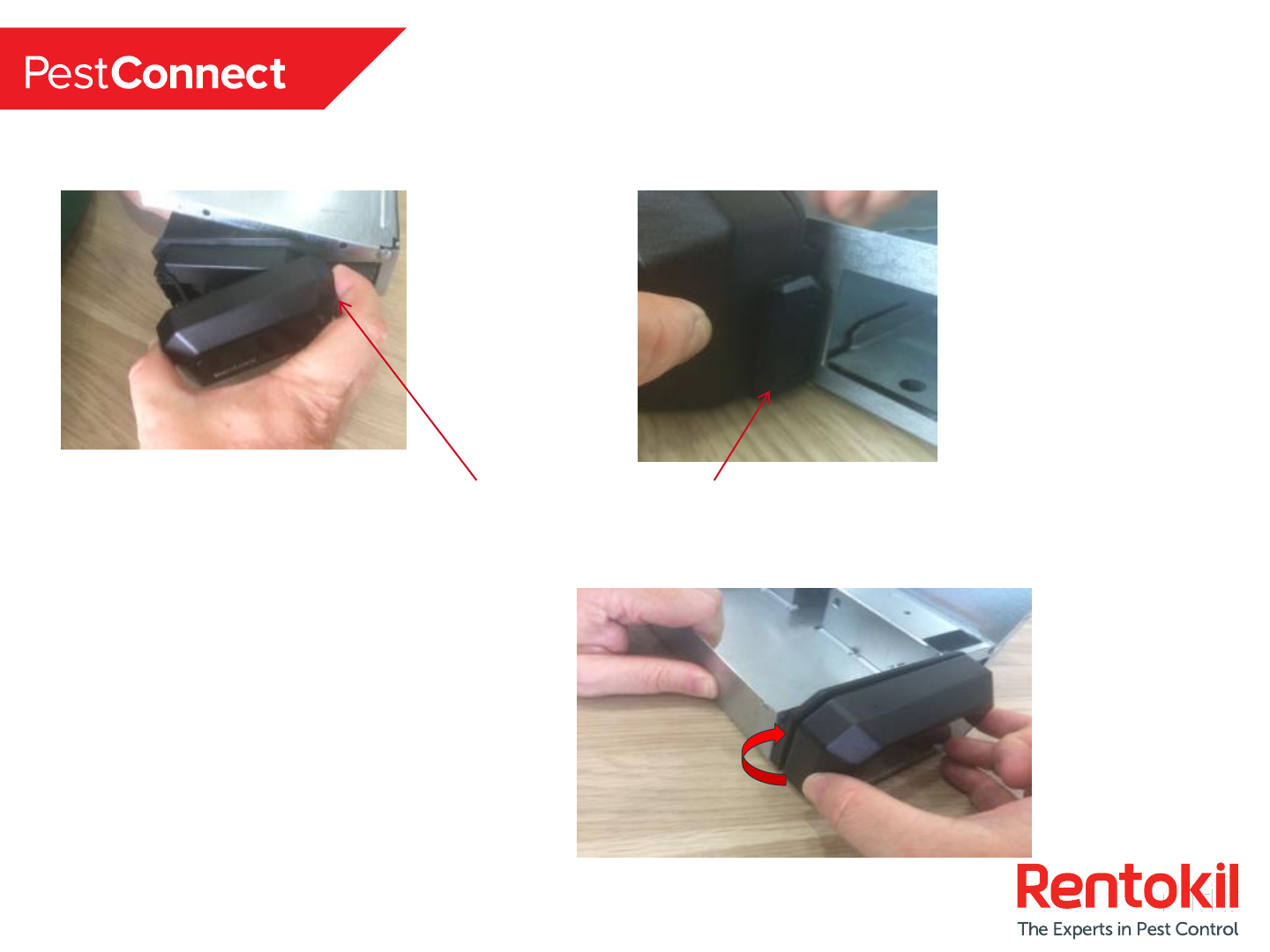
Install Step 9 –Replace the Cover
Right hand side first, ensuring clip is engaged
SNAP!
18
Fitment to Little Pete
To fit the MMT sensor to a Little Pete trap.
Follow all of the previous steps (identical hole configuration to JT Eaton Tin Cat).
Ensure label is flat and smooth
when finished.
Align label with top edge of
entrance housing
19
Connect Setup Sequence (1/2)
(Read all steps through before starting)
Upon initial Power Up the two LED’S
go into a Red Level Crossing Effect.
Open Trap and break the infra red
sensor beams.
20
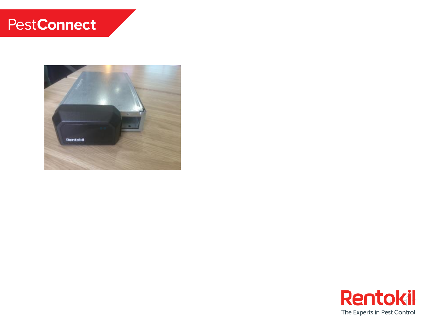
Connect Setup Sequence (2/2)
(Read all steps through before starting)
Close Lid LED’s now flash Red/Blue until
connected to the control panel at
which point 5 blue flashes will
indicate a successful connection.
Connection can take upto 2minutes
depending on the number of
repeaters installed, wait until the “5
blue flashes” are seen
Trap is now connected and ready to be placed in situ and left.
21
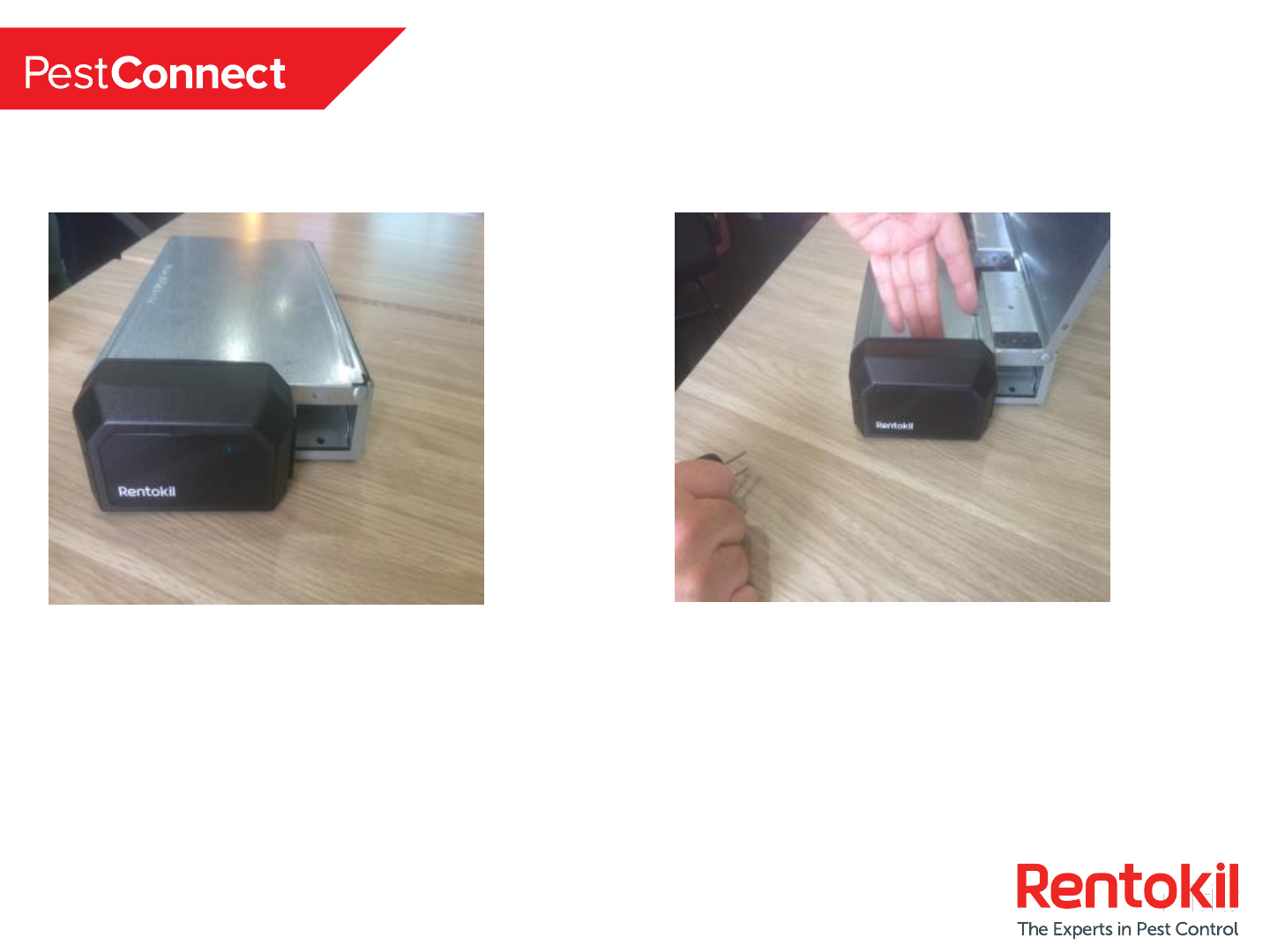
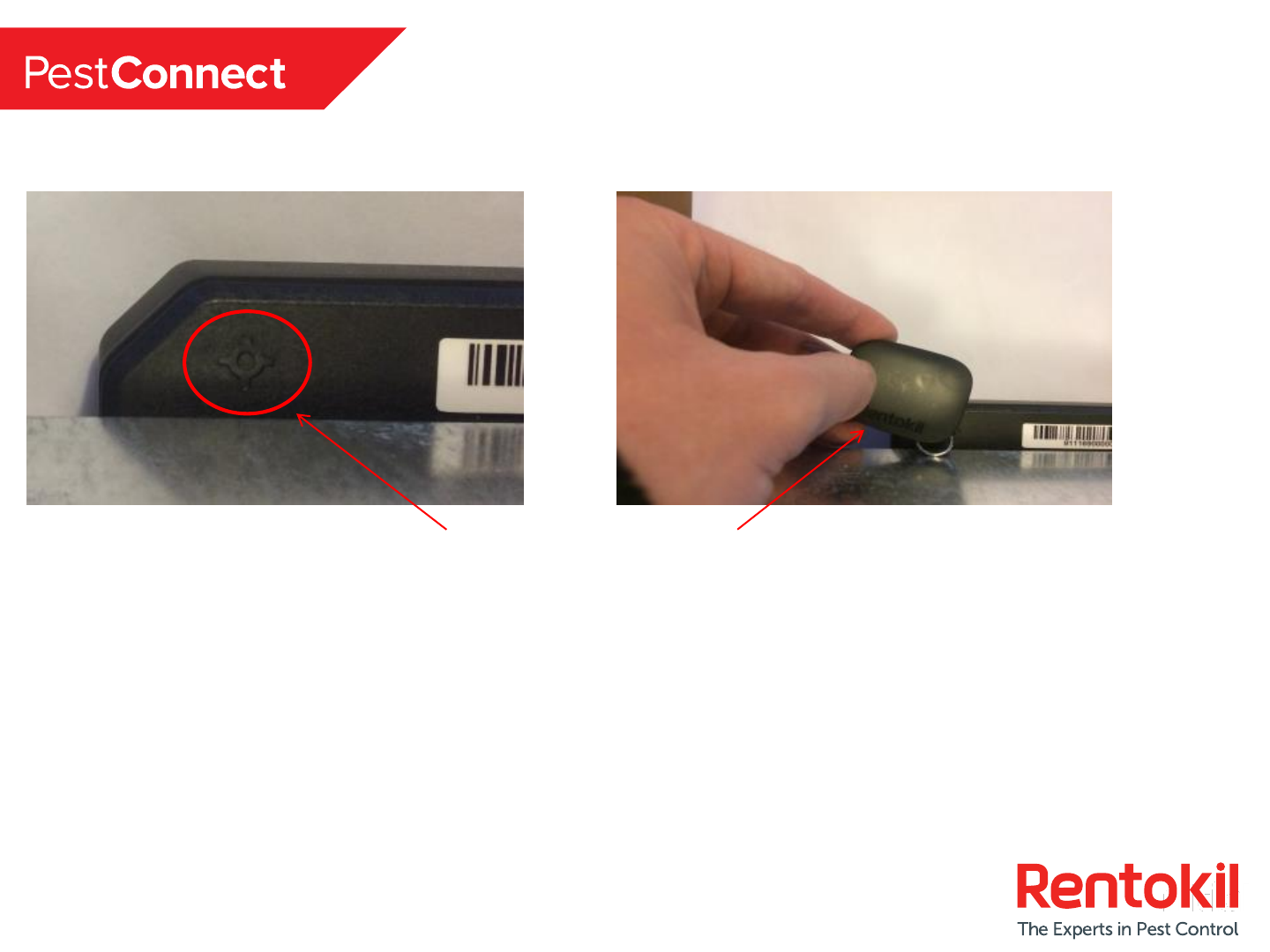
Technician Service Mode (1/2)
Place pest key over the magnet target area for a few seconds
and then remove and watch for blue LEDs (Level Crossing
Effect).
22
Technician Service Mode (2/2)
2 x Blue LED’s flash every 3
seconds indicating it is now ok to
open the lid of the trap to service.
Servicing can commence.
To rearm the trap swipe the magnet again and repeat the ‘Connect Setup Sequence’
by testing the IR’s and confirming the system has reconnected to the Control Panel.

23
LED’s & Troubleshooting
LED Sensor State Detail Action
Single Solid
Red
During Power on Battery Level Low Replace Battery
Red Level
Crossing LED
During Power on Trap awaiting sensor test Open Lid and break the infra red beams with hand
Red & Blue
Flashing LED
Setup Attempting connection to Control
Panel
Please wait
5 x Blue LED
Flashes
Setup /
Connection to
Control Panel
Sensor has successfully connected to
the Control Panel
No action required
5 x Red LED
Flashes
Setup /
Connection to
Control Panel
Sensor has been unable to connect
to the Control Panel.
Reduce the distance from sensor to Control Panel or install
a repeater.
Single flashing
blue LED
Setup One set of Infra Red sensors has
been tested, awaiting test of other
set.
Replace hand in trap and swipe left to right, place hand
closer to sensor. Replace sensor if fault persists
Solid Green
LED
Setup Infra Red Sensors have not been
triggered within 30 seconds
Begin setup again. Replace sensor if unable to clear fault.
Rapid Flashing
Green LED
Setup One set of IR’s has passed, one set
has failed and 30 seconds has
elapsed
Begin setup again. Replace sensor if unable to clear fault
2 x Solid Blue
LED’s
Mag swipe Sensor entering service mode Wait 3 seconds for the trap to enter service mode
Blue Level
Crossing LED
Service Mode Trap is in service mode, it is safe to
open the trap without sending false
trigger alerts to the Control Panel
Service trap
Solid RED LED
–Flashing
Blue LED
Entering Service
Mode
Low Battery has been detected Replace battery

Thank you