Rentokil Initial 1927 plc GSD-500349 LongReach Radio Module User Manual Control Panel
Rentokil Initial 1927 plc LongReach Radio Module Users Manual Control Panel
Contents
- 1. Users Manual - Control Panel
- 2. Users Manual - AutoGate Connect
- 3. Users Manual - Connect Radar
- 4. Users Manual - MMT
- 5. User Manual
- 6. User manual
Users Manual - Control Panel

Connect
Control Panel
Instruction Manual
This manual is based on the latest information and is provided subject to alteration.
Instruction Manual PestConnect / 2017 Version 1.2 GSD-100548
Relates to :
Connect Control Panel 2G R868 – 304769
Connect Control Panel 3G R915 – 304768
This product has LongReach Technology Inside
Instruction Manual Connect Control Panel/ 2017 Version 1.2 (GSD-100548)
Page 2
No part of this document may be reproduced, republished or retransmitted in any form or by any
means, whether electronically or mechanically, including, but not limited to, by way of photocopying,
faxing or recording without the express written permission. We reserve the right to revise this
document without the obligation to notify any person and/or entity. All other company or product
names mentioned are used for identification purposes only and may be trademarks of their respective
owners.
LIMITATION OF LIABILITY AND DAMAGES
The product and the softwares within are provided on an “as is” basis. The manufacturer and
manufacturer’s resellers (collectively known as “The Sellers”) disclaim all warranties, express, implied
or statutory, including and without limitation the implied warranties of non-infringement,
merchantability or fitness for a particular purpose, or any warranties arising from course of dealing,
course of performance, or usage of trade. In no event will the sellers be liable for damages or loss,
including but not limited to direct, indirect, special, wilful, punitive, incidental, exemplary or
consequential damages, damages for loss of business profits, or damages for loss of business of any
customer or third party arising out of the use or the inability to use the product, including but not
limited to those resulting from defects in the product or documentation. In no event shall the sellers’
total cumulative liability of each and every kind in relation to the product exceed the cost to replace
the product.
Product disposal instructions
for residential users
The Waste of Electrical and Electronic Equipment (WEEE) Directive (2002/96/EC) has
been put in place to recycle products using best available recovery and recycling
techniques to minimise the impact on the environment, treat any hazardous
substances and avoid increasing landfill. The symbol shown above and on the product
means that the product is classed as Electrical or Electronic Equipment and you should
not put it into your domestic waste bin. When you’ve no more use for it, please
dispose of the product according to your local authority’s recycling scheme. For more
information, please contact your local authority or the retailer
where you bought the product.
NOTICES

Instruction Manual Connect Control Panel/ 2017 Version 1.2 (GSD-100548)
Page 3
Safety Instructions
•This product is intended for indoor use only.
•Only use the power supply that is supplied with the product.
•Do not use the device if it is damaged.
•Only trained personnel should open the device.
•Do not expose the device to corrosive liquids.
•Do not use this device near to water sources.
•This device contains Radio Emitting devices and should not
be used near to life support systems.
Note: If the equipment is used in a manner not specified
by the manufacturer then the protection provided by
the equipment may be impaired.
Instruction Manual Connect Control Panel/ 2017 Version 1.2 (GSD-100548)
Page 4
Pest Connect Overview
Pest Connect is a system that enables remote monitoring of devices. Data from sensors is sent to
a Connect Control Panel which establishes a secure connection to a central server where the
data is entered into a database.
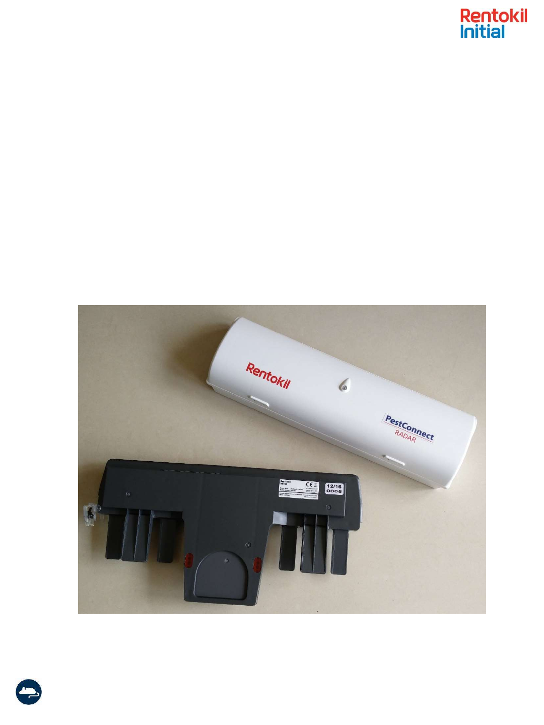
Typical sensors that are used in the Pest Connect system are the Radar Connect mouse trap and
the AutoGate Connect, shown below in Figure 1.
A typical installation will have many sensors communicating to the Connect Control Panel and a
single control panel can manage up to 300 sensors. Where necessary multiple Control Panels
could be deployed onto a site and up to 8 co-located control panels are permitted. In such a
system if the sensors fail to connect to the Control Panel they will scan for alternative Control
Panels to ensure high levels of connectivity.
Figure 1: Connect System Overview
Radar Connect
AutoGate Connect

Instruction Manual Connect Control Panel/ 2017 Version 1.2 (GSD-100548)
Page 5
Product Description
The control panel is the hub of the on-site installed system as all the data from the sensors is
collected here. The Control Panel passes the information onto Rentokil’s system servers using
mobile data technology. Every significant event is communicated to the servers, together with
hourly ‘health check’ reports, and daily sensor reports. The Control Panel also monitors for
devices which fail to make contact for a significant time and reports these to the Rentokil servers
to enable further action to be taken.
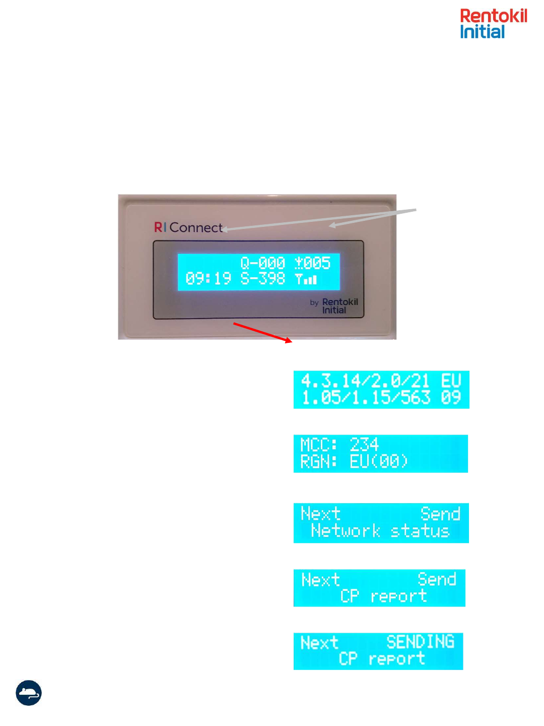
The Control Panel display shows a number of areas of information that show the current status
of the system. These are useful for providing confidence that all devices are connected and can
aid limited diagnostics onsite. The parameters displayed are shown below:
Server Time: This is always set to Greenwich Mean Time (GMT+00) and so does not change for
daylight saving time.
Number of Connected Devices: This is the number of sensors that are connected to the Control
panel. The Control Panel will expect regular data from these devices. If the sensors fail to
connect for 3 hours then this number will decrease.
Messages Sent: This is the number of messages from the sensors that have been sent to the
server. NOTE: If more than 1000 messages have been sent then the S- will become S+ in this
field.
Messages in Queue: This is the number of messages from the sensors that are waiting to be
sent to the server. An attempt to send the messages to the server is made every minute. After
three attempts if the Control Panel could not connect to the server it will not make any further
attempts to contact the server for one hour. Messages received during this hour will be entered
on the queue.
Mobile Signal Strength: This is an indicative value of the strength of the mobile signal. If there is
no connection then the telephone symbol will be flashing.
Messages Sent Mobile Signal Strength
Number of
connected devices
Messages Queued
Server Time
Instruction Manual Connect Control Panel/ 2017 Version 1.2 (GSD-100548)
Page 6
Diagnostic Screen
Using the magnet on the service key it is possible in display the diagnostic screen on the Control
Panel. Swipe the magnet on the left hand side of the display.
Swiping the magnet over the left hand point
(shown above) the diagnostic screen will be
Shown. This shows firmware versions and the
RF network region.
The MCC shows the country that the SIM card
connected to and the RGN shows the radio
region scheme that was used.
Additional swipes on the left hand point will
move to the next screen in the menu. If you
swipe over the right hand point this would send
a Network Status report to the server
Similarly, swiping on the left hand point will
bring up the next menu and swiping the right
will send the Control Panel report to the server.
Once the right hand point has been activated
It will indicate that it is indeed sending the report.
XX
Magnet swipe
points
X
X
X
X
X
Instruction Manual Connect Control Panel/ 2017 Version 1.2 (GSD-100548)
Page 7
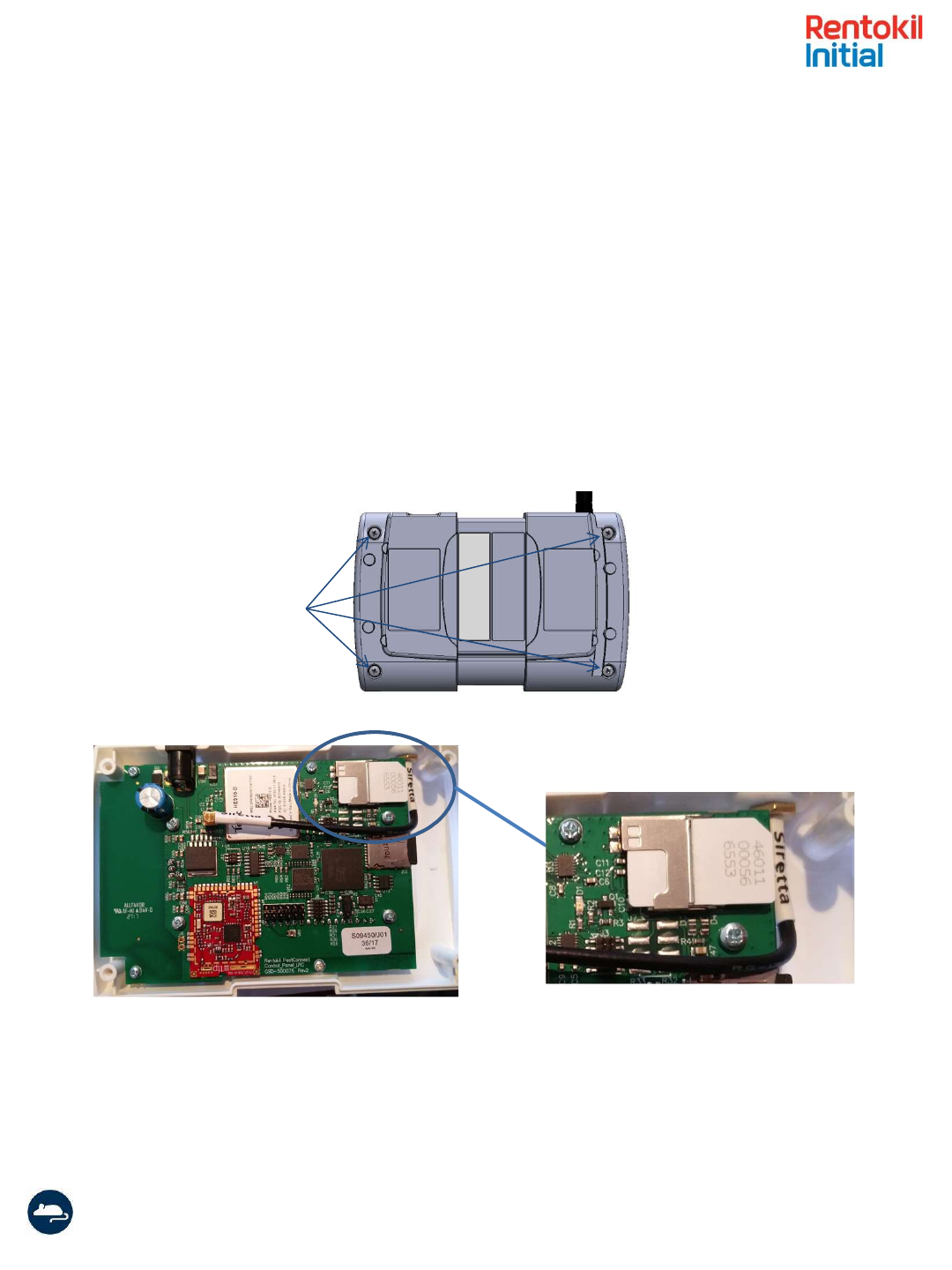
Inserting the SIM
The LongReach Control Panels are supplied with a global SIM card but if the SIM card needs
to be replaced then follow the following steps.
1) Ensure that the Control Panel is unplugged from the power supply.
2) Open the Control Panel by unscrewing the 4 screws. Take care when the enclosure is open
to not detach the antenna connector from the board.
3) Insert your SIM card into the slot as shown in Figure 1. The SIM card should be inserted
with the gold contacts facing the front of the Control Panel, and with the cut-off corner
outermost, see diagram below. IMPORTANT: Note the SIM card number and Control Panel
barcode to report to the System Administrator.
Figure 1: Inserting the SIM Card
4) Once you have inserted the SIM close up the Control Panel and re-tighten the screws.
5) The correct APN details for the particular SIM card will need to be written to a file on the
microSD card. Please contact central support for assistance with this.
Remove screws to
open control panel

Instruction Manual Connect Control Panel/ 2017 Version 1.2 (GSD-100548)
Page 8
Technical Details
Control Panel
Power Supply
Input Rating
110-240Vac 50-60Hz 0.5A
Output Rating
5V dc 2.6A current limited
Protection
Over Voltage: The output voltage shall be clamped by internal
protection zener
Short Circuit:
Output shut down and auto restart
Temperature:
No ignition, smoke or deformation of the case
Approvals
FCC PART15 CLASS B, EN55022 CLASS B, VCC CLASS II
UL/CUL, GS, CE & RoHs Compliant
Interfaces:
Local Area Network (LAN)
868-928M Hz depending on local Approvals
Rentokil Initial Propriatary LongReach Application Layer Protocol
Wide Area Network (WAN)
Connect Control Panel 2G
4 Band GSM /GPRS/EDGE: 850,900,1800,1900MHz
Connect Control Panel 3G
Dual UMTS/HSDPA 900/2100 MHZ with GSM/GPRS/EDGE 900/1800M Hz
fallback
WAN Antenna:
M oulded Antenna – T Bar GSM /GPRS/3G 2.5m cable SMA male -
ANTH7250A0200AI1
Gain
2.15 dBi
Polarisation
Vertical
Connect Device connectivity
M aximum number of Devices
300
Logging Capability:
Server time synchronization
+-500ms accuracy on the real time clock
Event driven logging
Capacity for 125 records of time tagged readings
SD card for long term audit trail
Physical:
Dimensions
145mm x 95mm x 40mm
M aterial
C130, 7030 Acrylonitrile Butadiene Styrene/Polycarbonate (ABS/PC)
Weight
256g
Operating Temperature
0ºC to +40ºC
Environmental rating
IP21
M ounting
Screw mounted with bracket - fixings enclosed
This product contains the LongReach radio module :
FCC ID: 2AK3PGSD-500349
IC ID: 22407-GSD500349
These will be shown on the approval label attached to the product.

Instruction Manual Connect Control Panel/ 2017 Version 1.2 (GSD-100548)
Page 9
Locating the Control
Panel
Before fixing the Control Panel to the wall it is important to verify that the location has
suitable mobile network coverage. Power up the unit and then temporarily place (or
hold) the Panel in the desired location.
When you first power up the unit you will see that the time in the bottom left of the
display is 00:00. Within 5 minutes the time is updated to show the server time (Note:
The server time is Greenwich Mean Time and so will not necessarily correspond to local
time). This means that the Control Panel has successfully made contact with the
Rentokil server. The reception strength bars on the bottom right of the display are
shown and if the Control Panel is correctly located then this should show 3 or more
bars. If the time is not updated or the Signal Strength indicator shows less than 3 bars
then you should investigate alterative locations for the Panel. Note: if the Control Panel
does not update the time within 5 minutes of being powered on then no further
attempts to connect with the server will be made for 1 hour. During a setup phase if
power is removed from the Control Panel and re-applied then another sequence of 5
minutely attempts will occur.
There are a number of error messages that can be displayed when the panel is first
connecting to the server, this often occurs when a Control Panel is connecting via a new
network, the Panel will continue to try to connect, so these messages may clear after a
short while. If they are still showing after 10 minutes then you should restart the Panel.
If the messages continue to show for 5 minutes a second time, then you should refer to
your PestConnect system contact.
Having successfully selected a location and proved that the signal is good, the bracket
can be mounted to the wall (as shown in the next section), the Control Panel attached
and then powered up. Once the time has updated you are ready to proceed with the
installation of the system (please refer to the equipment manuals for the devices that
are being installed for more details).

Instruction Manual Connect Control Panel/ 2017 Version 1.2 (GSD-100548)
Page 10
Problems with connection to the Control Panel from Sensors are very rare. Connection issues are typically only
related to low signal strength caused by obstructions in the Radio path.
It is useful for the installer to understand the type of obstructions that can cause issues, although radio waves
are very complex and sometimes work contrary to initial expectations, so the best method is to try it out.
Example 1 – Warehouse area with large, closely stocked produce containers
Radio frequencies can easily be absorbed by buildings and stock, so it is worth considering this when installing
the system. In particular, large, densely stored containers of produce (especially fine product such as grain or
nuts) can reduce signals very quickly if you try to go through them.
Finally be aware of empty racking when installing the system. What is empty today might not be tomorrow!
This is where the technician’s knowledge of the site can be very useful.
Example 2 – Metalwork
Metal reflects radio signals, so often helps bounce the radio waves around. However, radio doesn’t like going
through metal, especially if the metal is continuous.
A chilled storage area on one site showed much lower signal levels, because the foil coated insulation reduced
the signal significantly, compared to those even just outside the room. The solution here was to move the
control panel nearer to the effected area. In an extremely bad situation it may be necessary to add an
additional control panel. Fixing PestConnect units to metalwork, electrical conduit or cable tray can reduce
effectiveness of the system, so should be avoided if possible; ideally units should be at least 20cm clear of such
objects.
Example 3 – Adjacent systems
Multiple Pestconnect systems will work perfectly well next to each other, and it is possible for many systems to
be present on a single site. In many instances it can lead to a more robust system.
It is important to remember that radio waves do not respect building boundaries. Just because a system is all
set up in one building won’t mean that it will connect that way. An example of this can be where the end
sensors of two systems in separate buildings end up very close to one another. This can then provide a link
between the units in both building.
Equally the units don’t have to be physically close. A sensor installed at the edge on a warehouse could quite
likely find a better signal strength from a control panel in a building 200m away across an open courtyard or
car park than it can get from the control panel in the same building 50m away the other side of several rows of
fully stocked racking.
Fortunately this doesn’t matter, because each sensor is uniquely identifiable and registered to its location, so
its data will correctly appear in the server, no matter which route or Control Panel it used to do this.
Instruction Manual Connect Control Panel/ 2017 Version 1.2 (GSD-100548)
Page 11
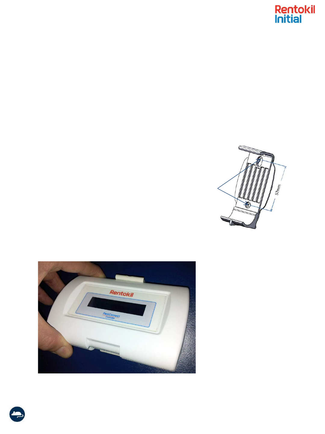
Installation
Once the best position for mounting the control panel is decided, mount the bracket to
the wall. Mark the position of the bracket holes on the wall (57mm between Ø4mm hole
centres, see Figure 4). Drill the appropriate holes to mount the bracket. Care should be
taken to avoid any hazards when drilling.
The Connect Control Panel is mounted to the bracket by firstly locating the top into the
wall bracket and then pushing the bottom edge into place (see Figure 5).
Figure 4. Wall Bracket
Ø4mm
Figure 5. Locate the top edge of Control Panel into the
wall bracket as shown and then push the bottom into place.
Instruction Manual Connect Control Panel/ 2017 Version 1.2 (GSD-100548)
Page 12
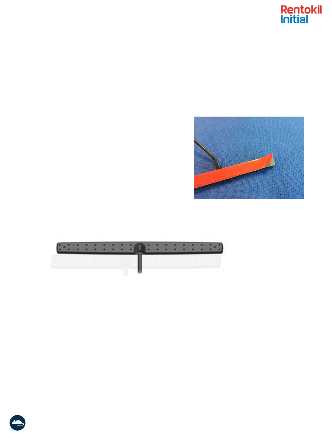
Mounting the Antenna
The extended antenna that is supplied has a 3m (~9ft) cable and should always be
mounted at a distance greater than 30cm from the enclosure. The antenna is simply
attached to a surface with adhesive tape as shown below.
Peel back protective
coating to reveal
adhesive tape
The antenna should be mounted as high as possible but at least 30cm from the
ceiling. It is also advisable to avoid mounting the antenna near to metal shelving
or cabinets as this will attenuate the signals.
To obtain the best possible signal strength the antenna should be stuck to a non-
conductive surface such as glass or wood. If the surface is metallic then ensure
that there is a spacer of at least 5cm from the surface.
Instruction Manual Connect Control Panel/ 2017 Version 1.2 (GSD-100548)
Page 13
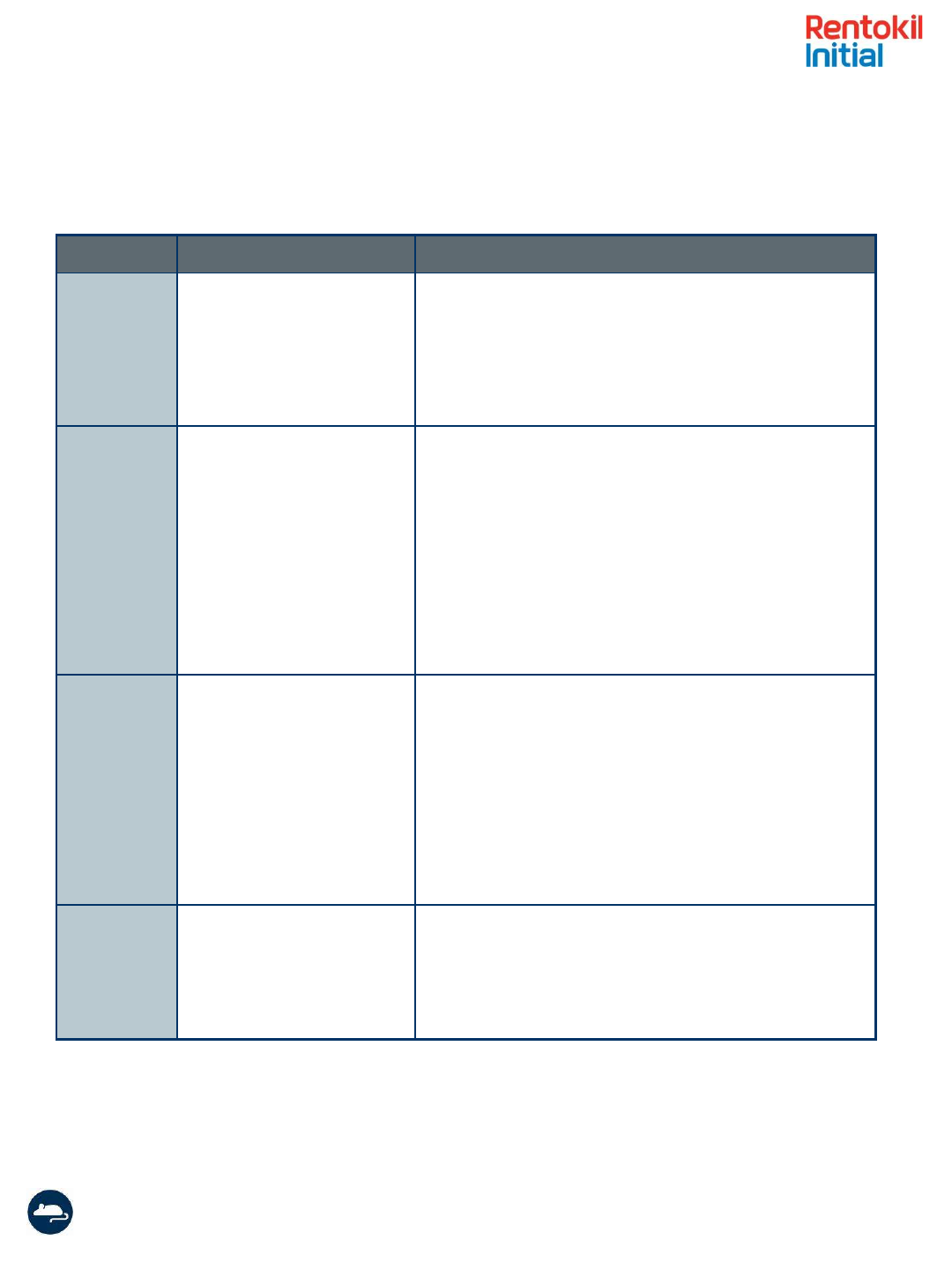
Troubleshooting
Message Meaning Possible Cause
No SIM card Control Panel cannot
identify the SIM
SIM inserted wrong way round or upside-down –
check and re-insert.
SIM contacts dirty – try cleaning with eraser
SIM faulty – try SIM in another communication
device to check that it works correctly.
No Signal The modem cannot detect
a signal from the mobile
network
Antenna not fitted, or not screwed on fully.
Control Panel location does not have sufficient
mobile network reception – try alternative
locations (check other communication devices
on the same network to see if they show signal)
Mobile network isn’t working – try mobile phone
on the same network to check this.
Faulty Antenna – try another antenna if you have
one.
Fault on the board – return to factory.
GPRS Fail The modem can detect a
network, but cannot
connect to it
Network Problem - The Control Panel will
automatically try to connect again. If this is still a
problem after 5 minutes then try restarting the
Control Panel.
SIM not authorised for data access – verify that
the SIM has been enabled by the network
provider. – You could try the SIM in another
communications device and try connecting to the
internet to prove data is enabled.
Modem Fail The Control Panel software
is getting no response from
the internal modem
Modem fault – The Control Panel will
automatically restart the modem showing the
message Restart Modem, if this fails you can try
restarting the Control Panel.
Instruction Manual Connect Control Panel/ 2017 Version 1.2 (GSD-100548)
Page 14
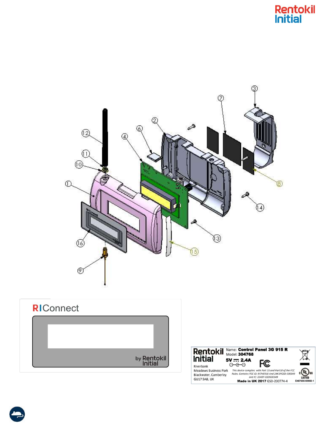
Exploded View
Sample Product Label
Sample Overlay Label