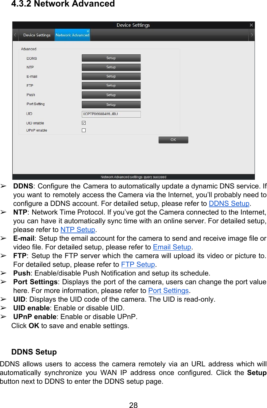
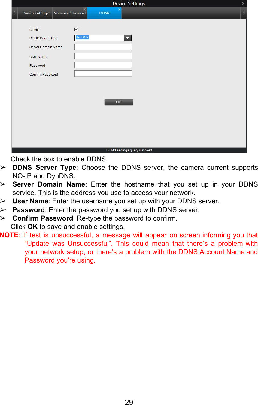
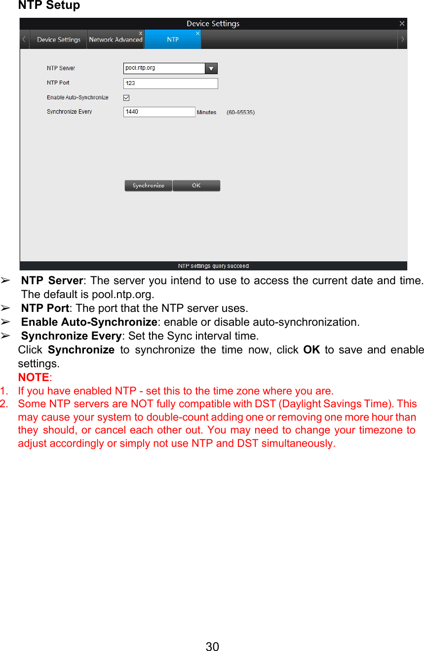
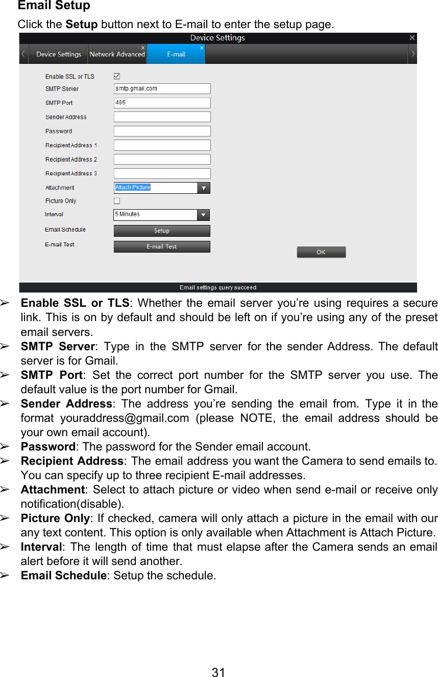
Reo link Digital Technology C2 WiFi IP Camera User Manual UserManual
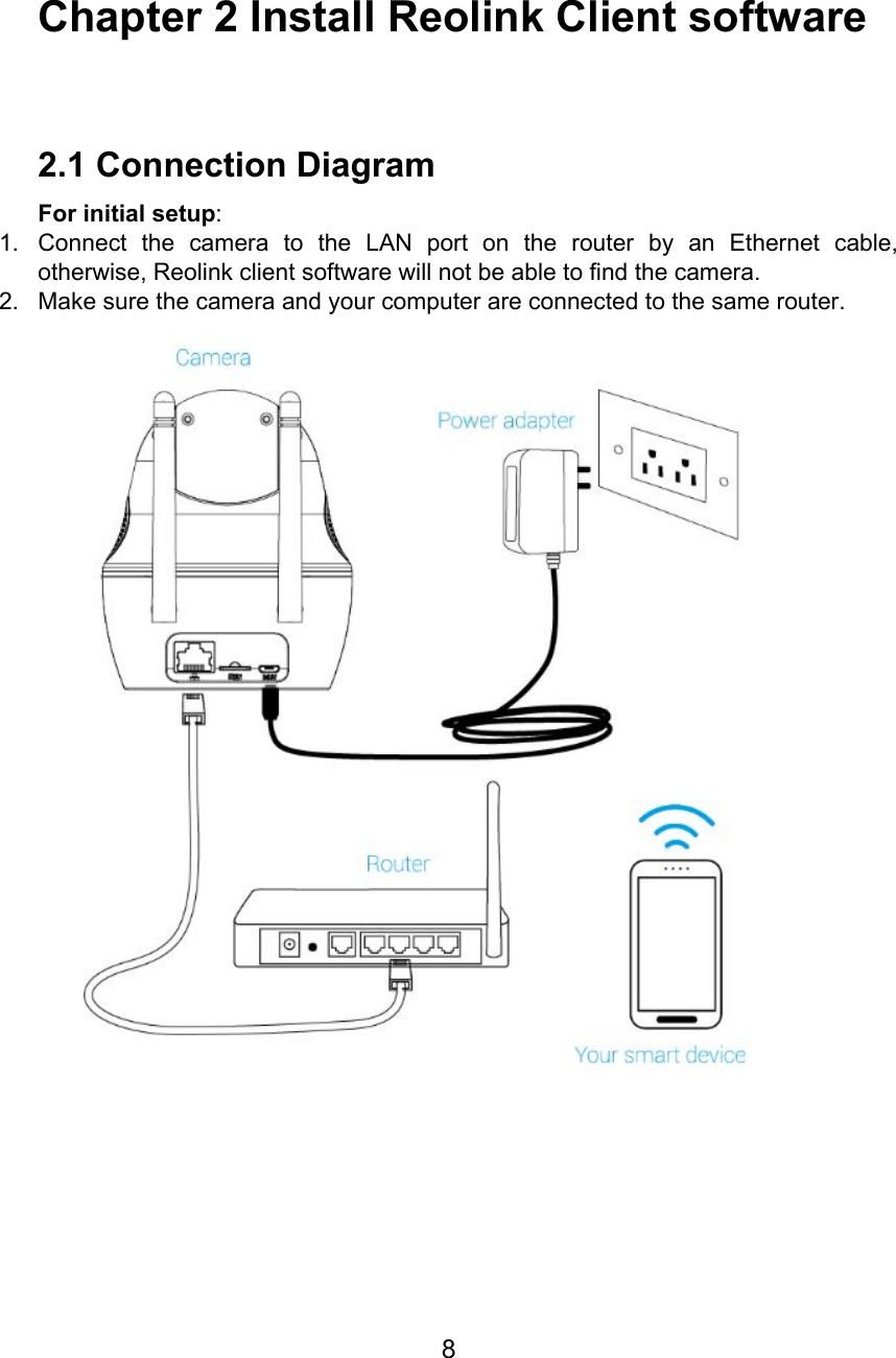
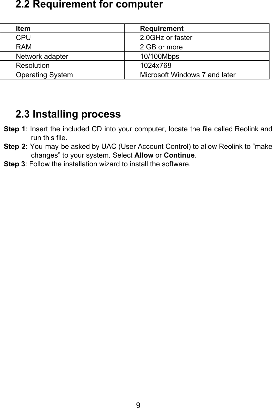
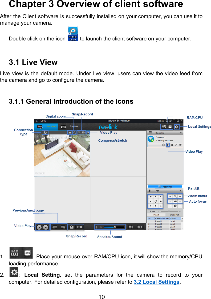
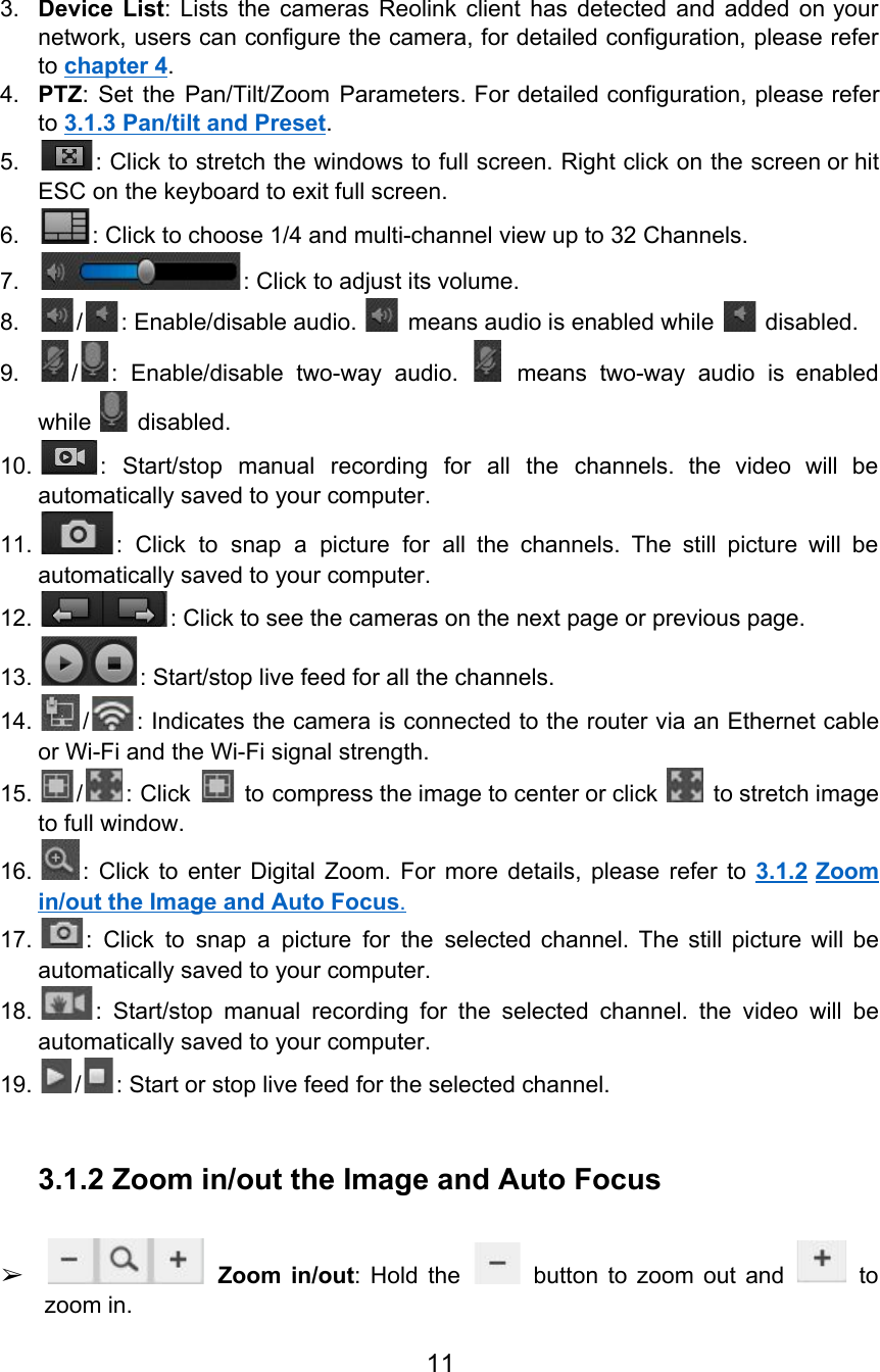
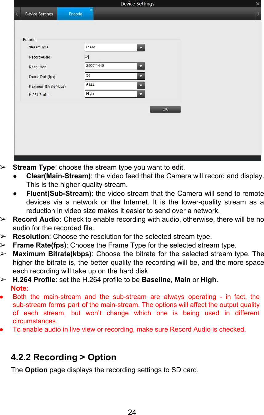
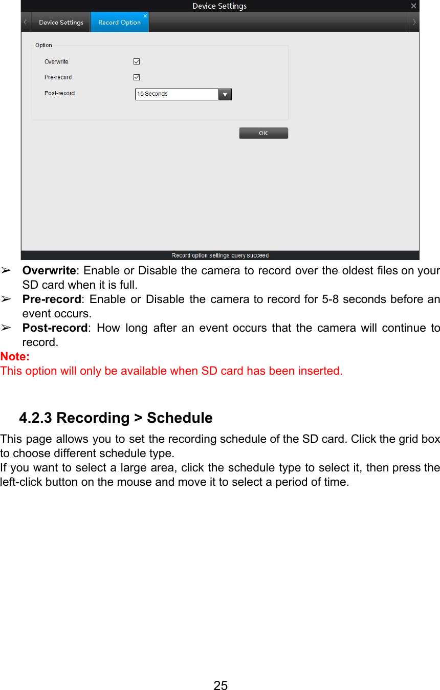
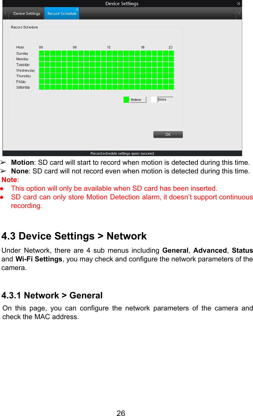
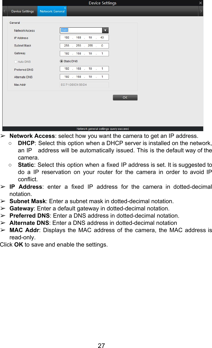
Reolink Digital Technology Co., Ltd. WiFi IP Camera UserManual
UserManual.wiki
>
Reo link Digital Technology
>
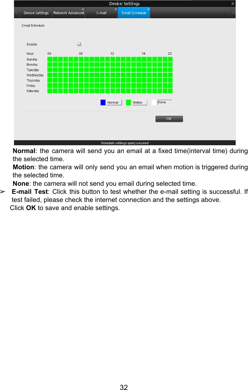
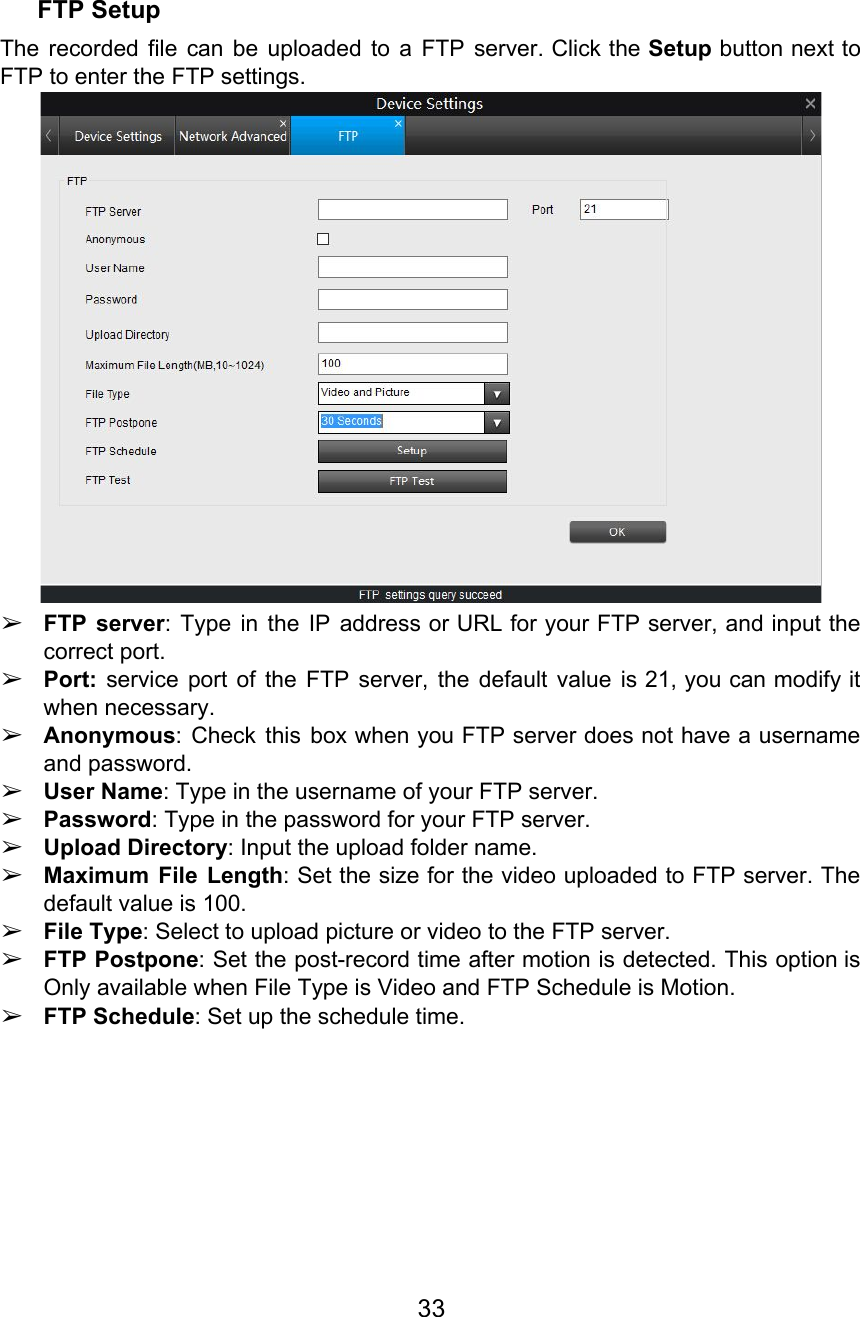
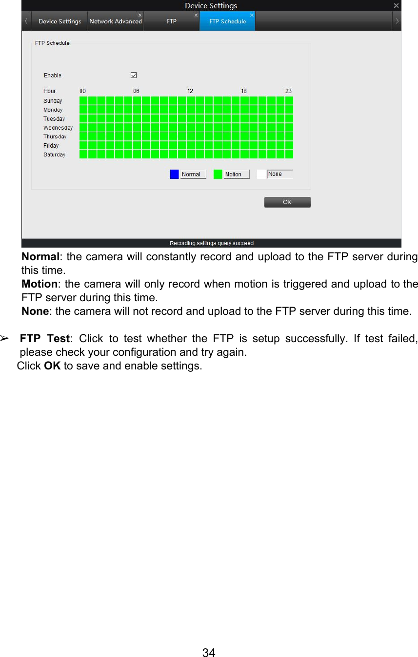
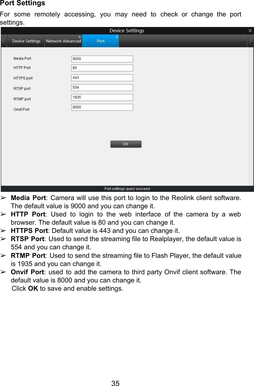
C2 User Manual
UserManual
Navigation menu
Upload a User Manual
Namespaces
Wiki Guide
HTML
PDF
Info
Views
User Manual
Discussion / Help
Navigation