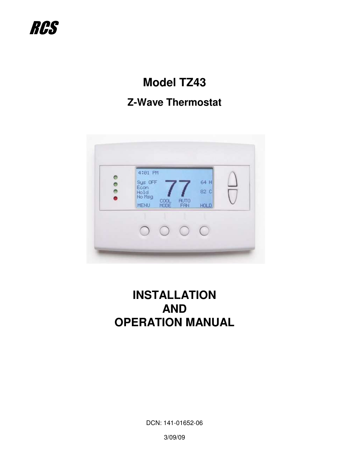
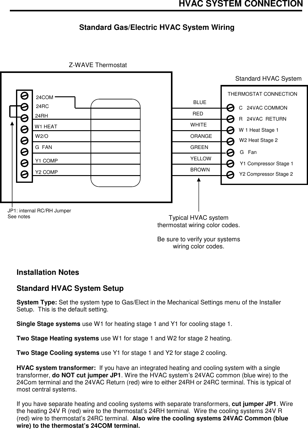
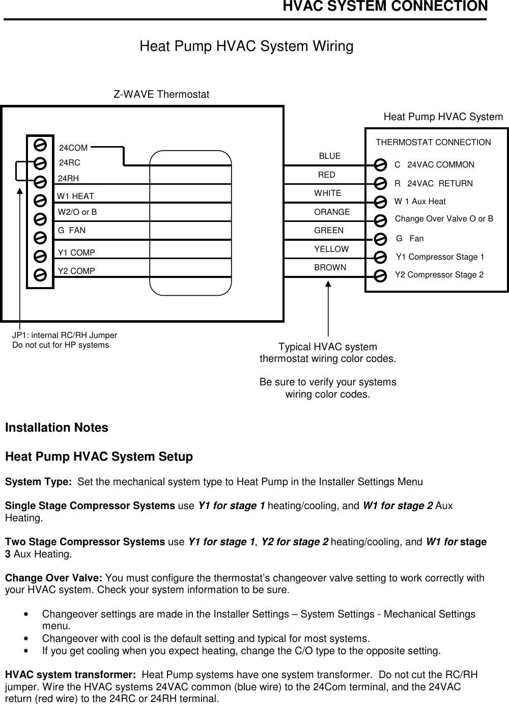
Residential Control Systems TZW005 Wireless Thermostat User Manual TZ43 Z WAVE INSTALLATION MANUAL 141 01652 06

Residential Control Systems Wireless Thermostat TZ43 Z WAVE INSTALLATION MANUAL 141 01652 06

user manual

                          Model TZ43   Z-Wave Thermostat                        INSTALLATION AND OPERATION MANUAL                DCN: 141-01652-06  3/09/09  RCS
Model:  TZ43  Z-Wave Thermostat     This manual applies to the following product revisions or later revisions up to the next manual revision release:   Product  Part No:  Firmware Revision Z-Wave Thermostat   001-01652-01  1.00.2         Document Revision History   Revision  Date  Changes 01  7/30/08  Original release 02  8/22/08  Updated Zwave Install description 03  9/22/08  Updated Zwave command class information 04  10/6/08  Added Zwave Inclusion and Basic ON/OFF information 05  3/8/09  Revised format.  Stat picture 06  3/9/09  Information Update     Product Specifications  Product Model:       TZ43 Product:         Thermostat for Heating and Cooling HVAC System control.           Z-Wave RF communications enabled   Thermostat Size:           5.7” wide x 4.0” height x 1.2” depth Display:         Graphical LCD, 2.75” x 1.5”, 64x128 pixel Backlight:         Yes, Blue/white, Controllable, on, off, timeout Contrast:         Adjustable on screen Buttons:         6 LEDs:           4 (3 green, 1 red) Power:         24VAC from HVAC System  HVAC System Type Compatible:   Standard (gas/electric) or Heat Pump Multistage System Compatible:   Standard HVAC Systems:   2 stage heating, 2 stage cooling   Heat Pump Systems:    3 stage heating (2 compressor, 1 aux heat), 2 stage cooling Heat Pump change over valve:  Selectable change over with cool or with heat Remote Sensors:      2, two wire, remote primary, averaging         Communications:       Z-Wave RF
 Table of Contents  Overview ......................................................................................................................................................4 Z-Wave® Installation...................................................................................................................................5 Inclusion and Exclusion .............................................................................................................................5 Thermostat Control Screen........................................................................................................................6 Temperature Display .................................................................................................................................6 Setpoint Display.........................................................................................................................................6 Thermostat Operation Buttons ..................................................................................................................7 Setpoint Up/Down Buttons.........................................................................................................................7 Clock Display.............................................................................................................................................7 LED Displays .............................................................................................................................................7 Setting Heating or Cooling Setpoints.........................................................................................................8 Schedules Screen....................................................................................................................................13 User Settings Screen...............................................................................................................................16 Thermostat Info Screen...........................................................................................................................22 Main Menu > Installer Settings    (Hidden Screen).................................................................................23 Installer Settings Summary......................................................................................................................26 HVAC System Connection........................................................................................................................27 HVAC System Compatibility ....................................................................................................................27 Remote Communications ........................................................................................................................27 HVAC System Operation and Setup........................................................................................................28 Standard HVAC System Types ...............................................................................................................28 Heat Pump HVAC System Types............................................................................................................28 Power.......................................................................................................................................................30 Standard Gas/Electric HVAC System Wiring ..........................................................................................31 Heat Pump HVAC System Wiring ...........................................................................................................32 FCC.............................................................................................................................................................33
 Overview   Z-Wave Thermostat   The Z-Wave thermostat provides for typical thermostat control of a central heating and cooling HVAC system plus has the added feature of Z-Wave communications for remote control.  The thermostat has a large, backlit graphical display, control buttons, status LEDs and a temperature sensor.  The thermostat can display multiple screens for different functions of the thermostat.  In the default thermostat control screen, shown below, it displays the current room temperature, heating and cooling setpoints, system mode, manual fan mode, time, and status information.                    Display operation  Thermostat control screen Normally the thermostat displays the thermostat control screen as shown above.  Using the “Menu” button, you can access other screens and functions of the thermostat.    Minimized Display Mode Optionally, you can set the thermostat to show only the temperature in a “minimized” display mode.   This mode can be set on or off in the thermostat “Users Settings” menu.   Backlight The thermostat has a backlit display for low light and night visibility.  It can be set to remain on constantly, or to turn off after a 20-120 second delay. These are selectable in the User Settings menu.  Status LEDs The thermostat has four LED’s that displays status information.  The LEDs have dynamic “on-screen” labels that change with the screen being displayed.  Function Control Buttons The thermostats buttons are “Soft Keys” meaning that they change functions when you change screens.  The function of the button is defined by “on-screen labels” that are dynamic and change when you change screens   Status Indicator LEDs  Setpoint Up/Down Buttons Function Control Buttons Heating (H)  And  Cooling (C) Setpoints On-screen dynamic  button labels
Z-Wave® Installation   Z-Wave controllers from various manufacturers may support the Z-Wave Thermostat General V2 Device class used by the RCS Z-WAVE Thermostat.  The following procedure will allow the thermostat to be added to a Z-Wave network.  General Programming Procedure (for controllers supporting the thermostat device class):  1.  Set your primary controller to Include mode, to add the thermostat as a node on your network (see your controller’s user manual for detailed instructions).  2.  In the Thermostat’s Main Menu, scroll down to the ZWave Install item.  Select the item.   3.  Press the YES button in the ZWave Install screen.  Your controller will indicate the thermostat was successfully added to its network (see your controller’s user manual for details). Also you can check if the thermostat was successfully added to the network by checking the ZHID (Home ID) and ZNID (Node ID) located in the Thermostat Info screen.  For other specific tasks such as adding the thermostat to Scenes or Groups, or deleting the thermostat from an existing network, use the Z-Wave Install procedure.  Note: Before adding the thermostat to a Z-Wave Network, check that it does not already belong to one by viewing the Home and Zone ID’s located in the Thermostat Info screen.  An un-configured thermostat should show zeros for both the Home and Zone IDs.  Consult your controller’s user manual for details on removing a device from a Z-Wave network.   Limited Setback Mode Operation.  If your controller does not support full thermostat device class functions, it may still be able to control the energy saving AWAY mode of the thermostat through basic ON/OFF commands similar to those used by lighting switches.  Sending the basic command ON, the thermostat will go into the AWAY mode and use the predefined setback setpoints.  These setpoints are set in the Main Menu Away Setpoints item.  Sending the basic command OFF, the thermostat will go back to the mode it was in before the On command was sent.   Inclusion and Exclusion Inclusion or exclusion is started by putting the controller into add node or remove node state and performing the General Programming Procedure outlined above.  As part of the process, the thermostat sends a node information frame at normal power.   Low power inclusion or low power exclusion is not possible.
 Thermostat Control Screen  Minimized Screen                        Main Thermostat Control Screen                      The main Thermostat Control Screen is the screen that is normally displayed on the thermostat.   Temperature Display The thermostat will normally display the current room temperature from the internal temperature sensor (or a remote sensor, if installed).    Setpoint Display The current heating and cooling setpoints are displayed next to the Setpoint Up/Down buttons.   7472 Press any button to return to the thermostat control screen The Minimized Screen shows only the room temperature.   It is displayed if you set the “Screen Timeout” in the User Settings Menu to a time greater than 0.    If set to 0, the minimized screen is disabled, and the main thermostat screen is normally displayed  MENU  COOL MODE 72 H AUTO FAN  HOLD 742 75 C 4:30 PM SYS OFF ECON HOLD NO MSG Status Indicator LEDs On-screen dynamic  button labels Setpoint Up/Down Buttons Heating (H)  And  Cooling (C) Setpoints Thermostat Operation Buttons L1 L2 L3 L4
 Thermostat Operation Buttons  Menu – go to the Main Menu Screen to select other thermostat settings screens System Mode – go to the System Mode screen to set thermostat operating mode Fan Mode – go to the Fan mode screen to set the fan mode Schedule Mode – go to the Schedule mode screen to set schedule mode or setback  Setpoint Up/Down Buttons Press either the Up or Down buttons to go to the Heating or Cooling Setpoint screen.   Clock Display The current time is displayed in the upper left corner of the main screen.  Set the clock from the User Settings Menu.  The time will blink when the clock has not been set.  LED Displays  The Thermostat Control Screen has the following LEDs and on-screen labels.      LED L1 Green:  System Operation mode. o  “SYS OFF” displayed >   HVAC system is OFF.  LED Off. o  “SYS MOT” displayed >  Minimum Off Time (MOT) delay On is active. LED Off. o  “HEAT ON”  displayed >  HVAC system is heating.  LED On. o  “COOL ON”  displayed >  HVAC system is cooling.  LED On. o  “HEAT MRT” displayed > HVAC system is Heating and Minimum Run Time (MRT) delay off is active. LED On. o  “COOL MRT” displayed > HVAC system is Cooling and Minimum Run Time (MRT) delay off is active. LED On.  LED L2 Green:  System Stage mode o  no display                  > 1st stage heating or cooling. LED OFF. o  “2nd Stg” displayed     > Stage 2 heating or cooling is active. LED On. o  “Aux Heat” displayed > Stage 3 heating is active. LED On.  LED L3 Green:  Schedule mode.  Shows state of Schedule Run/Hold Mode. o  “Run” displayed > Setback schedule is running.  LED Off. o  “Hold” displayed > Schedule is off, temperature setpoint hold in effect. LED On. o  “Away” displayed > Away setback mode is active. LED On.  LED L4 RED:  Alert LED.  Used for system alerts o  No display > No alerts. LED Off. o  Alert Text displayed > Specific alert text (Filter, Maint).  LED On.
Heating/Cooling Setpoint Setting  Setting Heating or Cooling Setpoints  Setpoint Up and Down Buttons   Press either the Up or Down button in the main Thermostat Control Screen to go to the current system operating mode (Heating or Cooling) Setpoint screen. as shown below.   Heating /Cooling Setpoint Adjustment Screen                       The UP and DOWN buttons adjust the setpoint temperature.  Pressing the UP button will increment the setpoint value by one degree and conversely, pressing the Down button will decrement the setpoint one degree.  Pressing and holding a button will cause the setpoint to continuously change until the button is released.    Setpoint Range: The setpoints can be set from 50°F to 90°F (4°C to 32°C) for heating or 55°F to 99°F (10°C to 37°C) for cooling.   Setpoint Push:  Note that you cannot lower the cooling setpoint below the heating setpoint.  The thermostat will “push” the heating setpoint lower if you try to lower the cooling setpoint below the heating setpoint.  It maintains a 3 degree separation between the heating and cooling setpoint.  The same is true for raising the heating setpoint above the cooling setpoint.  Again the thermostat will “push” the cooling setpoint up to maintain the 3 degree separation.  NOTE:  If the system mode is OFF, pressing either the Up or Down buttons will take you to the System Mode screen.  You must first set an operating mode before you can change the setpoints.   To change the Heat Setpoint you must be in Heating mode, to change the Cool Setpoint you must be in the Cooling mode.  If you are in Auto mode, the mode of the last system call will be the setpoint screen displayed.   Heating and Cooling setpoint setting buttons.  Adjust setpoint to desired temperature. HEATING SETPOINT 72 DONE Down Up Press Done button to select new setpoint and exit back to main thermostat screen.
System Mode    Press the System Mode button to display the System Mode selection screen.  System Mode Screen                       Mode Operation  OFF Mode: System is off.  No heating or cooling will come on.  If system was on, it will turn off.  HEATING Mode:  Only heating will occur.  COOLING Mode:  Only cooling will occur.  AUTO Mode:  Heating or cooling will come on according to the heating and cooling setpoints.  The system will automatically switch between heating and cooling modes as needed to maintain the setpoints.   Special Heat Pump Mode  EHEAT Mode:  An additional system mode, “EHEAT” for Emergency Heat will be displayed if the HVAC system type is set to Heat Pump.  If there is a compressor failure with the Heat Pump system, setting the mode to EHEAT will allow the supplemental Aux heat to come on first whenever there is a call for heating.  It also disables the compressor output to prevent further damage to the HVAC system.             Select system mode with Up or Down buttons.  . SYSTEM MODE OFF HEATING COOLING AUTO DONE Down Up Press DONE button to select mode and exit back to main thermostat screen. MODE Press MODE button to go to the System Mode screen
 Fan Mode  FAN Button  The FAN button controls the HVAC system’s MANUAL fan mode.  The current manual fan mode is displayed above the button.  Press the FAN button to go to the FAN MODE selection screen shown below.  Fan Mode Screen                        Normally the FAN mode is in the Auto mode (the system fan is automatically controlled by HVAC system).  If you want the FAN on manually, select the ON mode.  The fan will run continuously until it is turned off by selecting AUTO mode.   Optional Fan Mode  Fan Cycler.  If the Fan Cycler feature is enabled in the Installer Setup, the additional fan mode “Cycle” will be shown in the Fan Mode menu.  This mode cycles the fan on and off continuously for fresh air ventilation according to the settings in the Installer Setup.                     Select Fan mode with Up or Down buttons.  FAN MODE  AUTO ON DONE Down Up Press DONE button to select mode and exit back to main Thermostat Control Screen. FAN Press FAN button to go to the FAN Mode screen.
 Schedule Operation   Schedule Mode  The Schedule button sets the schedule operation to RUN or HOLD mode.  It also allows you to select an AWAY setback mode.  Pressing the Schedule button will take you to the SCHEDULE MODE menu screen as shown below.     Schedule Mode Screen                        Schedule Modes:  RUN Mode.  In the run mode, the thermostat schedule is running and setpoints will change according the times and temperatures in the internal schedule.    HOLD Mode.  This holds the current temperature setpoint settings.  The schedule operation is disabled.  AWAY Mode.  This is an energy saving setback mode.  When selected, the AWAY mode setback temperature setpoint settings are used.  It also inhibits schedule operation.  AWAY mode setpoints are set in the Main Menu “Away Setpoints” item.                  Select Schedule mode with Up or Down buttons.  . SCHEDULE MODE HOLD RUN AWAY DONE Down Up Press DONE button to select mode and exit back to main thermostat screen. HOLD Press the Schedule button to go to the Schedule Mode screen.
   Main Menu   The Menu button on the main Thermostat Control Screen selects the MAIN MENU screen.  The Main Menu is a list of the primary thermostat setting screens.  Selecting these items will take you to additional submenu screens for specific settings.                          Main Menu Selections  Note.  Some menu items are optional.  They must be enabled in the Installer Settings menu during the system setup to show up in the Main Menu list.  Schedules.  (Optional).  This screen is used to view and set the programmable setback schedules of the thermostat.    User Settings.  This screen is used to set the Clock, Filter Service, Maintenance Service, Screen Timeout, F/C mode, Sensor Calibration and Backlite/Display settings.  Usage  Graph.  Shows daily heating and cooling run time hours for a week.  Away Setpoints.  Sets the energy savings Away setback heating and cooling setpoints.    ZWave Install.  Used to install the thermostat into a ZWave network.  Thermostat Info Screen:  This screen shows the firmware versions of the Thermostat and the Zwave interface, ZWave network IDs, and the HVAC system type setup.        Select menu item with Up or Down buttons.  . Menu Selection Schedules User Settings Usage Graphs Away Setpoints DONE Down Up Press DONE button to exit back to main thermostat screen. SELECT Press SELECT button to go to the submenu screen.
Main menu - Schedules  Schedules is an optional menu item. It will only show up in the menu list if “Schedules” is enabled in the Installer settings for the thermostat.  Provides for local schedule control.  The Schedules Screen allows you to review and set the setback schedule for the thermostat.  The thermostat has a 4 x 7 schedule.  Four times a day can be selected for changes to the heating and cooling setpoints.  Each day of the week can have a different schedule.  Groups of days can be copied with the same schedule.  When the thermostat is set to “Run” mode, the schedule will be executed daily, with the setpoints being changed as per that days schedule stored in the thermostat.  “Hold” mode stops schedule operation and holds the current setpoints until changed manually or by network commands.  The Schedules Screen gives you the option of setting a custom setback schedule or to load one of two preset schedules.  Menu Options  • Heat and Cool:  You can change the individual day/hour and setpoints for the Heating and Cooling schedule by selecting this menu item.  • Preset:  Comfort:  This is a preset schedule with mild setbacks.  Select this menu item to load the Comfort schedule into the thermostat.  Confirmation screen will be displayed for Yes/No entry.  • Preset: EnergyMiser: This is a preset schedule with deeper setbacks.  Select this menu item to load the EnergyMiser schedule into the thermostat.  Confirmation screen will be displayed for Yes/No entry.   Schedules Screen                                  Select menu item with Up or Down buttons.  Select Schedule Heat and Cool Preset: Comfort Preset: EnergyMiser DONE Down Up Press DONE button to exit back to main thermostat screen. SELECT Press SELECT button to go to the submenu screen.
Main Menu - Schedules - Heat and Cool Schedule Screen  When you select the Heat and Cool Schedule menu item, the “day” schedule programming screen opens and the schedule for current day will be displayed.  Use the scroll buttons to highlight the data to be modified.  Once the data has been highlighted, use the +/- buttons to change the value of the data.   To copy a days schedule to another day or group of days, move the cursor to “C” on the bottom right of the schedule screen.  When you highlight the “c”, the button below will become “Copy”.  Press this button to change to the Copy Schedule Screen.      Schedule Screen                                Increase or decrease the time or temperature setting with the Up/Down buttons.  Saturday Schedule              Time         Heat  Cool Morn    06:00 A       70     78 Day      08:00 A       62     85 Even    04:00 P       70     78 Night   10:00 P       62     82          C DONE     Press DONE button to exit back to Main Menu screen. NEXT Press NEXT button to go to the next day (or if Copy is selected, go to Copy Schedule screen). + - Use the scroll buttons to navigate forwards or backwards through the time and temperature settings.
Main Menu - Schedules - Heat and Cool - Copy Schedule  The Copy Schedule screen is a sub screen of the Schedule screen. The Copy Schedule screen allows you to copy a day’s schedule to another day or group of days.  First select the day to be copied in the Schedule screen.  Scroll to the “c” at the bottom of the Schedule screen to highlight it.  The “Next” button will change to the “Copy” button. Press the “Copy” button to open the Copy Schedule screen.  Scroll through the days and select the days you want to copy the schedule to by setting the “N” under each day to “Y” by using the Yes/No buttons.  After selecting all the days desired, press the “COPY” button.  Exit the Copy Schedule screen with the “DONE” button.   Copy Schedule Screen                     Select Yes or No to days to copy schedule to using Up/Down buttons.  Copy Saturday Schedule   Sun Mon Tue Wed Thu  Fri       N     N     N     N      N     N          DONE     Press DONE button to exit back to day schedule screen. COPY Press COPY button to copy the schedule to the days with Y selected. Yes  No Use the scroll buttons to navigate forwards or backwards through the days of the week.
Main Menu - User Settings  The User Settings screen allows you to set or change various user options of the thermostat such as the Clock, Filter and Maintenance service timers,  Minimized Screen timeout, Fahrenheit/Celsius mode, Sensor Calibrations, and Display settings.  User Settings Screen                      Menu items:  Set Clock:  Go to the Clock setting screen.  Filter Service: Go to the Filter Service Screen.  Sets/resets the filter timer/alert.  Maint Service: Go to the Maintenance Service Screen.  Sets/resets the maintenance timer/alert.  Screen Timeout: Set the display timeout time in seconds. Options are 0 or 15 to 120 (default set to 0 seconds).  This is the time before the main thermostat screen reverts to the Minimized Screen (temperature display only), after the last button press.  Minimized Screen feature is disabled by setting this time to “0”.  F/C Settings:  Go to the F/C Settings Screen.  Select which temperature display mode you desire, Fahrenheit (F) or Celsius (C).  Sensor Calibration:  Go to the Sensor Calibration Screen. This screen allows you to set the calibration of the internal and remote temp sensors.   Backlite/Display:  Go  to the Backlite/Display settings screen.  This menu allows you to set the backlight timeout period and adjust the display contrast.      Select menu item with Up or Down buttons.  User Settings Set Clock Filter Service Maint Service Screen Timeout     0 DONE Down Up Press DONE button to exit back to Main Menu screen. SELECT Press SELECT button to go to the submenu screen.
Main Menu - User Settings - Set Clock    The Set Clock screen allows you to set the Thermostat’s internal clock.  To set the Time and Date, move the cursor with the navigation arrows until the data you want to change is highlighted.   Using the + and – buttons to increment or decrement the data to the desired setting.  When finished, press the SET button to return to the Main Menu screen or wait for screen to timeout.  NOTE:  If the clock has been reset by an extended power outage, the Clock display on the thermostat screen will be blinking.  Pressing the MENU button will take you directly to this screen to set the clock.    Set Clock Screen                            Increase or decrease the time or date setting with the Up/Down buttons.  Set Clock Time:  07:09 PM Date:  03/07/09 Day:   Sat BACK     Press BACK button to exit back to User Settings screen without setting the time. SET Press SET button to set the time and Exit. + - Use the scroll buttons to navigate forwards or backwards through the time and date settings.
Main Menu - User Settings - Filter Service   The Filter Service screen will show the accumulated Filter Runtime hours as well as the Service Interval that will be used to trigger a Filter Message.  Any type of HVAC operation that causes the HVAC system fan to run will cause the Filter Runtime value to increase.  When the Runtime hours equals the Service Interval hours, the Red LED will flash along with a “Filter” message to remind you to replace the filter.  Pressing the Menu button will take you to the Filter Service screen.  Once the filter has been replaced, press the Reset button to reset the Filter Runtime value to zero.  The Service Interval period can be changed using the +/- buttons.     Filter Service Screen                                     Filter Service   Filter Runtime         120 HRS Service Interval      300  HRS         DONE     Press DONE button to exit back to User Settings screen. RESET Press RESET to reset the runtime counter and exit. Use +/- buttons to increase or decrease the service interval hours. + -
Main Menu - User Settings - Maint Service   The Maintenance Service screen will show the accumulated Heat and Cool Runtime hours as well as the Service Interval that will be used to trigger a Maintenance Message.  Any HEAT or COOL type of HVAC operation will cause the respective Runtime values to increase.  When the combined HEAT and COOL Runtime hours equals the Service Interval hours, the Red LED will flash along with a “Maint” message to remind you your HVAC system may require periodic maintenance.  Pressing the Menu button will take you to the Filter Service screen.  The Reset button can be pressed and the HEAT and COOL Runtime values will be reset to zero.  The Service Interval period can be changed using the +/- buttons.     Maintenance Service Screen                                       Maintenance Service Heat Runtime          120  HRS Cool Runtime            20  HRs Service Interval     3000  HRS         DONE     Press DONE button to exit back to User Settings screen. RESET Press RESET to reset the runtime counters. Use +/- buttons to increase or decrease the service interval hours. + -
Main Menu - User Settings - Sensor Calibration   The Sensor Calibration screen allows you to change the temperature calibration of the internal temperature sensor.  You can change the temperature calibration by +/- 7 degrees.  When the Sensor Calibration screen is selected it will show the current temperature calibration (The (75) in the example screen below) and the current number of degrees of offset being applied (1 deg in the example).  If the sensor’s actual temp is (74) with 0 degrees of offset and you want it to be 75, then press “+” to add 1 deg and it will show (75).  To change the temperature calibration, use the scroll buttons to select the internal or a remote sensor.  Once selected, use the + and – buttons to change the temperature calibration to the desired setting.  The value shown in the (xx) is the calibrated or offset temperature that you want the sensor to show.  You can refresh the info on this screen by pressing the right hand (blank) button.  When you close this screen, it may take a few seconds for the temperature displayed on the main thermostat screen to update to the new temperature.   Sensor Calibration Screen                                     Select menu item with Up or Down buttons.  Menu Selection Internal       (75)   0 Remote 1    n/a    0 Remote 2    n/a    0 DONE Down Up Press DONE button to exit back to main thermostat screen. Press +/- buttons to increase/decrease the calibration offset.   + -
Main Menu - User Settings - Backlite/Display   The Backlite/Display screen allows you to set the Backlite timeout and contrast.  Backlite Timeout: Sets the time from last button press that the backlite will timeout and turn off.  The timeout value is adjustable from 0 or 20 to 120 seconds.  If set to “0”, the Backlite will always be ON.  If set in the range of 20 to 120 seconds, the Backlite will turn OFF after the selected time expires.  Contrast: Sets the contrast level of the LCD display, adjustable from 0 to 20.  Use this control to adjust the darkness of the display.  To light and the display looks faded, too dark and dark lines will appear in the display.  Typically 10 is the correct setting.  Adjust as needed.    Backlite Settings Screen                                  Select menu item with Up or Down buttons.  Backlite/Display Backlite Timeout    0 Contrast                10 DONE Down Up Press DONE button to exit back to User Settings screen. Press +/- buttons to increase/decrease the setting.   + -
Main Menu - Thermostat Info    The Thermostat Info screen displays the current configuration of the Z-WAVE Thermostat. This information is useful for quick check of firmware versions and HVAC system setup.  It also shows the Zwave network setting.  Thermostat information displayed is:  • Thermostat - Model and firmware version number. • Z-Wave Settings - ZWave Firmware version, ZWave Node ID, ZWave Home ID • System Type - Standard or Heat Pump HVAC system • Fan Type – if HVAC type = Standard:  Gas or Elect   OR • Changeover – if HVAC type = Heat Pump: Changeover with cool or changeover with heat.    When finished viewing this screen press the Done button to return to the main Menu screen or wait for screen to timeout.   Thermostat Info Screen                           Thermostat Info TZ43                Ver 01.00.01 ZVER: 01.02.5            ZNID: 003 ZHID: 00.00.07.76 System Type:          Standard Fan Type:                Gas          DONE Press DONE button to exit back to Main Menu screen.
Main Menu > Installer Settings    (Hidden Screen)  The Installer Settings screen is a hidden screen designed for installer use only.  Do not change any settings in this screen unless you are a qualified service technician.  Changing these settings will affect the operation of the heating/cooling system.   To enter this screen, go to the main menu selection screen and press and hold the two inner buttons for 3 seconds until the Installer Settings screen appears.  The Installer Settings screen displays the current internal settings of the thermostat.  You can view and change the settings from this screen.  Scroll to the desired function and use the +/- buttons to change.  Installer Settings Screen                        Installer Settings Menu items  Display Lock:      Range: Y or N        Default: N Y = Display LOCKED N = Display unlocked Allows you to lock or unlock the thermostat buttons.  When the buttons are locked, you can still access the main menu, but you will not be allowed to select any menu options.  The Installer Settings hidden button operation is always operational, allowing you to return to this screen and turn Display Lock off.    Service Mode Submenu   Test Mode    Range: Y or N    Default: N Y= Test mode on.  Reduces all delays to 10 sec for quicker system testing N= Test mode off.  Normal system delays.  CAUTION:  in test mode all system safety delays are shorten.  Do not operate the system compressor in test mode.  Disconnect Y1 or Y2 outputs if test mode on a live system.   Select menu item with Up or Down buttons.  Installer Settings Display Lock          N Service Mode System Settings Max Heat SP         90 DONE Down Up Press DONE button to exit back to Main Menu screen. Press +/- buttons to increase/decrease the setting.   + -
System Settings Submenu  Mechanical Settings Submenu     Type    Range: Gas/Elec or Heatpump  Default: Gas/Elec         Selects HVAC type, Gas/Electric or Heatpump      Fan Type  Range: Gas or Elec    Default: Gas     Selects the Fan type if system is Gas or Electric      C/O Type  Range: w/Cool or w/Heat  Default: w/Cool         Set the Heatpump Changeover type    2nd Stage Heat Range: Y or N      Default: N         Enables the 2nd Stage Heat operation      Aux Heat (HP)  Range: Y or N      Default: Y         Enables the Auxiliary Heat operation.  Typically the Aux Heat will be heat-strips in a Heatpump system    2nd Stage Cool  Range: Y or N      Default: N         Enables the 2nd Stage Cool operation  Schedule Enable  Range: Y or N      Default: N  When enabled, the local thermostats scheduler function is enabled.    Recovery enable  Range: Y or N    Default: N For Heat Pump Systems.  Intelligent setback recovery is an automatic advance start of heating to allow the system to be at setpoint by the schedule time, without the use of Aux heating.  Note on Delta Settings : The Delta T Setting is the delta, or difference between, the setpoint and current temp for determining when a heat or cool call comes on.  The “delta” is the number of degrees away from setpoint.  H/C Delta       Range: 3 - 15 degrees.     Default: 3. Sets the minimum separation between heating and cooling setpoints.  Attempts to lower the cooling below the heating setpoint by this amount will PUSH the heating setpoint down to maintain this separation.  Same for setting the heating setpoint above the cooling setpoint, it will PUSH the cooling setpoint up to maintain this separation.     Heating Delta Stage 1 ON    Range: 1 to 8 degrees    Default: 1 Sets the delta from setpoint that stage 1 heating starts.    Heating Delta Stage 1 OFF    Range: 0 to 8 degrees    Default: 0 Sets the delta from setpoint that stage 1 heating stops. Stage 1 turns off at setpoint + Delta Stage 1.   Heating Delta Stage 2 ON  Range: 1 to 8 degrees    Default: 2 Sets the delta from setpoint that stage 2 heating starts.    Heating Delta Stage 2 OFF    Range: 0 to 8 degrees    Default: 0 Sets the delta from setpoint that stage 2 heating stops. Stage 2 turns off at setpoint + Delta Stage 2.   Heating Delta Stage 3 ON   Range: 1 to 8 degrees    Default: 3 Sets the delta from setpoint that stage 3 heating starts.    Heating Delta Stage 3 OFF    Range: 0 to 8 degrees    Default: 0 Sets the delta from setpoint that stage 3 heating stops. Stage 3 turns off at setpoint + Delta Stage 3.   Cooling Delta Stage 1 ON  Range: 1 to 8 degrees     Default: 1 Sets the delta from setpoint that stage 1 cooling starts.
  Cooling Delta Stage 1 OFF    Range: 0 to 8 degrees    Default: 0 Sets the delta from setpoint that stage 1 Cooling stops. Stage 1 turns off at setpoint - Delta Stage 1.   Cooling Delta Stage 2 ON   Range: 1 to 8 degrees     Default: 2 Sets the delta from setpoint that stage 2 cooling starts.    Cooling Delta Stage 2 OFF    Range: 0 to 8 degrees    Default: 0 Sets the delta from setpoint that stage 2 Cooling stops. Stage 2 turns off at setpoint - Delta Stage 2.   Max Heat SP       Range: 50F to 90F (4C-32C)    Default: 90F (32C) Sets the maximum heating setpoint value.  Will not ramp or accept setpoints higher that this maximum.     Min Cool SP       Range: 55F to 99F(10C-37C)    Default: 55F (10C) Sets the minimum cooling setpoint value.  Will not ramp or accept setpoints lower than this minimum.        Minimum Run Time     Range: 1- 9 Minutes  Default: 3 Sets the minimum run time before a heating/cooling cycle can turn off.   Sets heating/cooling cycle time. Prevents rapid cycling.    Minimum Off Time      Range: 5-9 Minutes   Default: 5 Sets the minimum off time before another heating/cooling cycle can begin.  Provides compressor short cycle protection.    Fan Cycler Submenu The fan cycler function cycles the HVAC system fan for an ON period followed by an Off period continuously.  Used to provide minimum air ventilation requirements.  When the Fan ON time is set to a value greater than 0, an additional “Cycler” FAN mode is present when pressing the FAN button.  Fan ON Time      Range: 0-120 minutes    Default: 0 (=OFF)  Fan OFF Time      Range: 10-120 minutes    Default: 10
Installer Settings Summary  Setting  Range  Default   Display Lock  Y or N  N  Locks out front buttons F/C Mode  C or F  F   Screen Timeout  0, 20-120  0  seconds        Schedule Enable  Y or N  N          Max heat setpoint  50F-90F (4C-32C)  90F (32C)   Min cool setpoint  55F-99F(10C-37C)  55F (10C)   Min Run Time (MRT)  1 – 9  3   Min Off Time (MOT)  5 – 9  5   Mechanical - Type  Std or HP  Std   Mechanical - Fan Type  Gas or Elec  Gas   Mechanical - C/O Type  w/Heat or w/Cool  w/Cool   Mechanical - 2nd Stage Heat  Y or N  N   Mechanical - Aux Heat  Y or N  Y   Mechanical - 2nd Stage Cool  Y or N  N          Filter Interval    300   Maint Interval    3000          H/C Delta  3 – 15  3   Heat Delta Stage 1 On  1 – 8  1   Heat Delta Stage 1 Off  0 – 8  0   Heat Delta Stage 2 On  1 – 8  2   Heat Delta Stage 2 Off  0 – 8  0   Heat Delta Stage 3 On  1 – 8  3   Heat Delta Stage 3 Off  0 – 8  0   Cool Delta Stage 1 On  1 – 8  1   Cool Delta Stage 1 Off  0 – 8  0   Cool Delta Stage 2 On  1 – 8  2   Cool Delta Stage 2 Off  0 – 8  0   Fan Cycler ON time  0 – 120  0  0 = Fan Cycler OFF Fan Cycler Off Time  10 – 120  10
HVAC System Connection   The thermostat connects to the HVAC system’s thermostat connections just like a traditional thermostat does.      HVAC System Compatibility  The thermostat is compatible with most heating and cooling systems.  There are two types of HVAC systems:  Standard (gas/electric) and Heat Pump systems. The system type is selectable from the Installer Screen – System Settings – Mechanical Settings submenu.  For Standard HVAC systems: Gas heating or Electric heating.  For Heat Pump HVAC systems: supports changeover valve operation for either changeover with cooling or changeover with heating.   Multi-Stage HVAC Compatibility  For Standard HVAC systems, the HVAC outputs support 2 stages of heating and 2 stages of cooling.  For Heat Pump HVAC systems, the HVAC outputs support 3 stages of heating (2 compressor/1 Aux Heat) and 2 stages of cooling.  Remote Communications  The Z-Wave thermostats have a Z-Wave communications module for communicating to control systems with Z-Wave capability.
HVAC System Operation and Setup   General Heating and Cooling Operation  In the HEATING mode, the heating system will be turned on at one degree below the setpoint and will turn off at the setpoint.  This turn on and turn off offset is referred to as the heating setpoint “delta T” and is adjustable in the Installer Settings menu of the THERMOSTAT.  It is set to the one degree operation by default.  In the COOLING mode, the cooling system will be turned on at one degree above the setpoint and will turn off at the setpoint.  Similarly, the cooling setpoint delta T is adjustable in the Installer Settings menu.  In the AUTO mode, the system will switch between heating and cooling as determined by the heating and cooling setpoints and the current temperature.  Once in a heating or cooling mode of operation, the normal one degree setpoint control is maintained.  Setpoint Push.  Heating and cooling setpoints are forced to maintain a separation between them, with a default setting of 3 degrees.  If the heating or cooling setpoint is changed to be within the setpoint delta, the system will automatically “push” the other setpoint to maintain the setpoint delta separation.  The H/C setpoint delta is also adjustable in the Installer Settings menu of the THERMOSTAT.  Standard HVAC System Types       Gas or electric heating systems are considered “Standard” HVAC systems.  These systems consist of an indoor furnace/blower assembly and an outdoor AC condensing unit (for those systems with air conditioning installed).  These systems in general are referred to as central forced air HVAC systems.  You must configure the Thermostat to match your HVAC system type for correct system operation.  Setup  Standard System Type Selection To configure the Thermostat for standard Gas/Electric HVAC system operation, change the Type in the Installer Settings – System Settings – Mechanical Settings menu option to Gas/Elec.   Fan Type Selection Gas systems do not require a fan output for heating operation.  Set the Fan Type in the Installer Settings – System Settings – Mechanical Settings – Fan Type to GAS.  Electric (and hydronic) heating systems do require a fan output with the call for heating.  Set the Fan Type in the Installer Settings – System Settings – Mechanical Settings – Fan Type to ELEC.    Be sure to check your HVAC system’s requirements.    Heat Pump HVAC System Types   Heat Pump HVAC systems are combined heating and cooling systems.  The system consists of an indoor “air handler” (a blower fan and coil assembly) and an outdoor unit.  Heat pumps change from heating mode to cooling mode by switching the refrigerant flow using a “changeover” or “reversing valve”.   In both heating and cooling operation the compressor and fan outputs are on and the state of the changeover output determines if heating or cooling is being provided.   Heat pumps can have one or two stages of compressor operation plus an optional third stage of electric heat strips.  The third stage of heating will be turned on when the current temperature falls 3 deg below the current setpoint and will turn off at the setpoint.
 Setup  Heat Pump System Type Selection To set the Thermostat for Heat Pump HVAC operation, change the Type in the Installer Settings – System Settings – Mechanical Settings menu option to Heat Pump.  Changeover Type Selection Most heat pump systems are designed to work normally in the heating mode and require a change over output for cooling output.  Change the C/O Type in the Installer Settings – System Settings – Mechanical Settings menu option to match your system needs.  Changeover with Cooling:  Set C/O Type to w/Cool (This is the default setting).   Changeover with Heating:  Set C/O Type to w/Heat.  Note: during Heat Pump operation the changeover relay, once engaged, will stay on until the opposite HVAC call occurs.   Check your HVAC system requirements for correct settings.     Minimum Run Time (MRT)  The thermostat has a Minimum Run Time after the start of any heat or cool call.  This minimum run time assures even heating and cooling cycles.  Minimum Run Time will keep the system on even if you change the setpoint to a temperature that would satisfy the call, until the MRT expires.   Changing the Mode to OFF will cancel the MRT and the system will turn off immediately. MRT can be adjusted in the Installer Settings Menu of the THERMOSTAT.  Note:  MRT status is shown in the thermostat System Status LED on-screen label.     Minimum Off Time (MOT)     The thermostat has a Minimum Off Time after any heat or cool call.  This delay prevents rapid heating/cooling cycles and also provides “short cycle protection” for compressor calls.  This delay may be noticeable when you change a setpoint and it does not respond immediately due to another call that has recently completed and the MOT delay timer is preventing the restart of the system.  The MOT delay time can be adjusted in the Installer Settings Menu of the THERMOSTAT.  There is a minimum of 5 minutes delay to assure compressor protection.  Note:  MOT status is shown in the thermostat System Status LED on-screen label.
 INSTALLATION  Power  The thermostat requires 24VAC power from the HVAC system it is controlling.  Connect the 24VAC Common (typically the Blue wire/terminal) and 24VAC R (typically the Red wire/terminal) from the HVAC system to the thermostats HVAC System terminal block 24VCom and 24V RH or  24V RC terminals (the RH and RC terminals are default tied together)     Common or Split Transformer Systems Most HVAC systems have a common heating and cooling transformer. A trace is connected to tie the RH and RC inputs together for this configuration.  If you have a system with separate heating and cooling transformers, you will need to split the RH and RC jumper by cutting the trace on the PCB.  When wiring split systems, wire the heating systems 24VAC R (red wire) to the thermostat’s RH terminal, and wire the cooling systems 24VAC R to the thermostat’s RC terminal.  Also wire the cooling systems 24VAC Com to the thermostat’s 24VAC Com terminals.    Note: Do not split RC/RH for Heat Pump systems!
HVAC SYSTEM CONNECTION   Standard Gas/Electric HVAC System Wiring                        Installation Notes  Standard HVAC System Setup   System Type: Set the system type to Gas/Elect in the Mechanical Settings menu of the Installer Setup.  This is the default setting.  Single Stage systems use W1 for heating stage 1 and Y1 for cooling stage 1.  Two Stage Heating systems use W1 for stage 1 and W2 for stage 2 heating.  Two Stage Cooling systems use Y1 for stage 1 and Y2 for stage 2 cooling.  HVAC system transformer:  If you have an integrated heating and cooling system with a single transformer, do NOT cut jumper JP1. Wire the HVAC system’s 24VAC common (blue wire) to the 24Com terminal and the 24VAC Return (red) wire to either 24RH or 24RC terminal. This is typical of most central systems.  If you have separate heating and cooling systems with separate transformers, cut jumper JP1. Wire the heating 24V R (red) wire to the thermostat’s 24RH terminal.  Wire the cooling systems 24V R (red) wire to thermostat’s 24RC terminal.  Also wire the cooling systems 24VAC Common (blue wire) to the thermostat’s 24COM terminal.  RED GREEN WHITE YELLOW Z-WAVE Thermostat W1 HEAT JP1: internal RC/RH Jumper See notes  24RC ORANGE BROWN 24RH G  FAN W2/O Y1 COMP Typical HVAC system thermostat wiring color codes.  Be sure to verify your systems wiring color codes. Y2 COMP  24COM Standard HVAC System G   Fan W 1 Heat Stage 1 Y1 Compressor Stage 1 R   24VAC  RETURN C   24VAC COMMON THERMOSTAT CONNECTION  Y2 Compressor Stage 2 W2 Heat Stage 2 BLUE
HVAC SYSTEM CONNECTION   Heat Pump HVAC System Wiring                       Installation Notes  Heat Pump HVAC System Setup    System Type:  Set the mechanical system type to Heat Pump in the Installer Settings Menu  Single Stage Compressor Systems use Y1 for stage 1 heating/cooling, and W1 for stage 2 Aux Heating.  Two Stage Compressor Systems use Y1 for stage 1, Y2 for stage 2 heating/cooling, and W1 for stage 3 Aux Heating.  Change Over Valve: You must configure the thermostat’s changeover valve setting to work correctly with your HVAC system. Check your system information to be sure.  •  Changeover settings are made in the Installer Settings – System Settings - Mechanical Settings menu.   •  Changeover with cool is the default setting and typical for most systems.     •  If you get cooling when you expect heating, change the C/O type to the opposite setting.  HVAC system transformer:  Heat Pump systems have one system transformer.  Do not cut the RC/RH jumper. Wire the HVAC systems 24VAC common (blue wire) to the 24Com terminal, and the 24VAC return (red wire) to the 24RC or 24RH terminal. RED GREEN WHITE YELLOW Z-WAVE Thermostat W1 HEAT JP1: internal RC/RH Jumper Do not cut for HP systems  24RC ORANGE BROWN 24RH G  FAN W2/O or B Y1 COMP Typical HVAC system thermostat wiring color codes.  Be sure to verify your systems wiring color codes. Y2 COMP  24COM Heat Pump HVAC System G   Fan W 1 Aux Heat Y1 Compressor Stage 1 R   24VAC  RETURN C   24VAC COMMON THERMOSTAT CONNECTION  Y2 Compressor Stage 2 Change Over Valve O or B BLUE
FCC    INFORMATION TO USER  This device complies with Part 15 of the FCC Rules.  Operation is subject to the following two conditions:  (1)  This  device  may not cause  harmful interference, and (2)  This device must  accept any interference received, including interference that may cause undesired operation.  This equipment has been tested and found to comply with the limits for Class B Digital Device, pursuant to Part 15 of the FCC Rules.  These limits are designed to provide reasonable protection against harmful interference in a residential installation.  This equipment generates and can radiate radio frequency energy and, if not installed and used in accordance with the instructions, may cause harmful interference to radio communications.    However,  there  is  no  guarantee  that  interference  will  not  occur  in  a  particular installation.  If this equipment does cause harmful interference to radio or television reception, which can be  determined  by  turning  the  equipment  off  and  on,  the  user  is  encouraged  to  try  to  correct  the interference by one or more of the following measures.  •  Reorient or relocate the receiving antenna •  Increase the separation between the equipment and receiver •  Connect the equipment into an outlet on a circuit different from that to which the receiver is connected •  Consult the dealer or an experienced radio/TV technician for help  Any changes or modifications not expressly approved by the party responsible for compliance could void the user’s authority to operate the equipment.

Navigation menu