Resmed Sensor Technologies BM11 Sensor Module User Manual Manual
Resmed Sensor Technologies Ltd Sensor Module Manual
Manual

BM11_DOC2 v01-Oct11
BM11
Movement & Breathing Sensor
OEM Installation Instructions
BiancaMed Ltd
Dublin
Ireland
Phone: +353 1 716 3755
www.biancamed.com

Page 1
Table of Contents
About the BM11 Movement & Breathing Sensor ..................................................................................2
BM11 Technology Overview ............................................................................................................2
Module Specifications.........................................................................................................................3
Physical Specifications.....................................................................................................................3
Radi o Frequency Sensor Specifications .............................................................................................4
Electrical Specifications ...................................................................................................................6
Analogue Sensor Data .....................................................................................................................7
Environmental Specifications...........................................................................................................9
Parts & Materials ................................................................................................................................9
Testing Standards/Conformance to Collateral/ International Standards ...............................................10
Module Mounting & Product Integration Considerations ....................................................................11
Interference from Internal Wireless Devices ...................................................................................11
Information for OEM User Leaflet & Labeling .....................................................................................12
Mandatory .......................................................................................................................................12
Device Label: ................................................................................................................................12
User Leaflet: .................................................................................................................................12
Inf ormat i on ......................................................................................................................................13
Device Information .......................................................................................................................13
Device Placement .........................................................................................................................13
Device Specifications.....................................................................................................................14

Page 2
About the BM11 Movement & Breathing Sensor
The BM11 sensor is a complete non-contact breathing detector on a small circuit board. The
sensor uses Radio Frequency, centred on 10.525 GHz, which is a license-free operating band.
The BM11 is designed to be easily incorporated into Original Equipment Manufacture rs’ own
products, where the breathing rate and rhythm of a subject is required.
The key features are:
• Small antenna horn: easy to incorporate the circuit board into another product.
• Slender and enclosed circuitry: gives maximum flexibility in enclosure design.
• Very low emitted power, less than home broadband router or mobile phone BlueTooth.
• Non-contact: ease of use and comfort for the customer.
• Very short range: the sensor is selective.
The sensor has 2 channels, I and Q, providing movement and breathing data. The sensor data is
provided as an analogue signal.
BM11 Technology Overview
The sensor module is designed to emit very low power RF waves that are reflected by a human
subject within the field of the sensor. The reflected waves received by the sensor contain
information about the motion of the human subject based on the Doppler Effect. The system
detects movement of the subject due to breathi ng and also due to change in position.
The sensor module translates the movement of the human subject into electrical signals. To
maximise the information obtained from the sensor, the signals are converted into two voltage
signals. These signals are referred to as the ‘I’ and ‘Q’ channels. The sensor module outputs
these two analogue voltage signals and they are presented to the OEM host device for
digitising.
There is a companion software library available, that extracts breathing, movement and
sleeping information from the sensor data. This software library can reside within the OEM
application and provide the information under the application’s control. See BiancaMed
product specification BM012_DES01 for details.
Page 3
Module Specifications
The BiancaMed BM11 Sensor is a 10.525GHz motion detector. It comprises a motherboa rd
PCBA, an integral RF PCBA, die cast RF metalwork and a custom plastic anti-tamper enclosure.
Physical Specifications
Parameter
Value
Remarks
Circuit board dimensions
44.5mm by 77.5mm by 6 mm
See diagram below
Complete assembly (including
anti-tamper enclosure)
dimensions
63.75mm (x) by 79.3mm (y)
by 10mm (z) main body of
enclosure,
13.8 mm (z) at enclosure
hump
22.5mm (z) max by horn, see
Figure 2 below
Complete assembly weight <100 gm
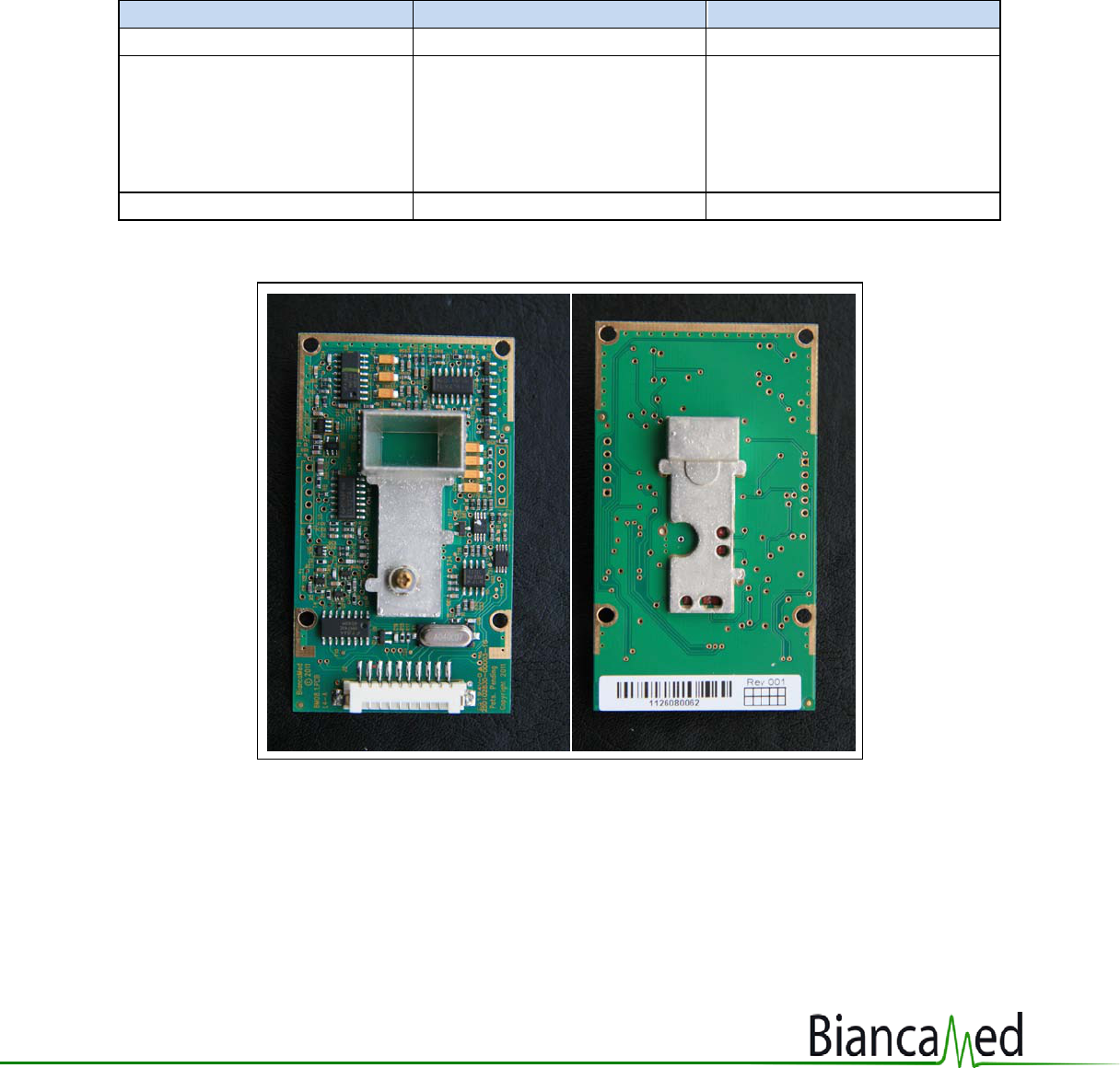
Figure 1: PCB Layout, showing the Antenna Horn on the top side and the connector at the
bottom
Page 4
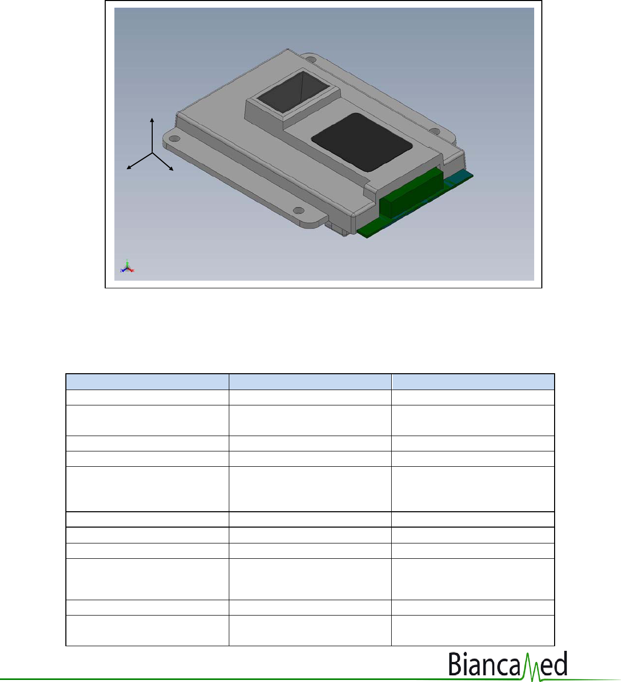
Figure 2: 3-D Model of PCB Enclosed in Anti-Tamper Enclosure
NB: A Solidworks 3D model is available from BiancaMed upon request.
Radio Frequency Sensor Specifications
Parameter Value Remarks
Centre frequency f
c
10.525 GHz +/- 10 MHz
Peak RF power (conducted at
antenna)
2 dBm nominal power (Rated power +/- 50%)
Spurious Conducted Power <-26dBm
OBW (99%) OBW will lie within fc±15 MHz
and OBW will be ≤18 MHz
RF t/x Pulse
1000nS
PRF 500 KHz
RF Duty Cycle 50%
Antenna Type
Broadside pyramidal HORN
reflector antenna with planar
monopole feed.
Antenna Gain
6 dBi @ f
o
f
o
= fundamental frequency
Antenna Beam width
Azimuth*
60-70 degrees ( 3dB)
see sample beam pattern
below at Figure 3a
x
y
z
Page 5
Parameter Value Remarks
Antenna Beam width
Elevation*
50-60 degree (3dB) see sample beam pattern
below at Figure 3b
Typical breathing detection
range
Can detect bio-motion signals
inside 1.5M. Cannot be
measured outside 1.8M.
Target aspect is not
important, ie the target can
be sitting, lying down, face up
face down, on side etc.
Comply with following
Regulatory Approval
Specifications:
ARIB-std T73v1.1
Electrical safety: IEC60065:2005
EMC & ESD: IEC60601-1, 1-2 (2nd)
FCC part 15.245
• *The antenna characterization applies to the unhoused sensor module – antenna
characteristics may vary when inserted into an OEM housing – it is the responsibility of
the system integrator to ensure that the final antenna characteristics are fit for purpose.
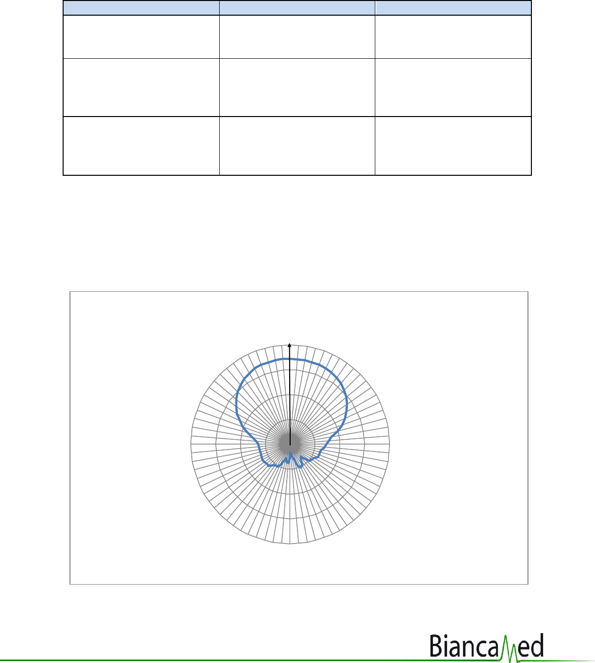
Figure 3a: Azimuth Beam Pattern (arrow depicts line of sight of the sensor)
-30
-20
-10
0
10
0
5
10
15
20
25
30
35
40
45
50
55
60
65
70
75
80
85
90
95
100
105
110
115
120
125
130
135
140
145
150
155
160
165
170
175
180
185
190
195
200
205
210
215
220
225
230
235
240
245
250
255
260
265
270
275
280
285
290
295
300
305
310
315
320
325
330
335
340
345
350
355
10.525 GHz combined polarisation for azimuth
Page 6
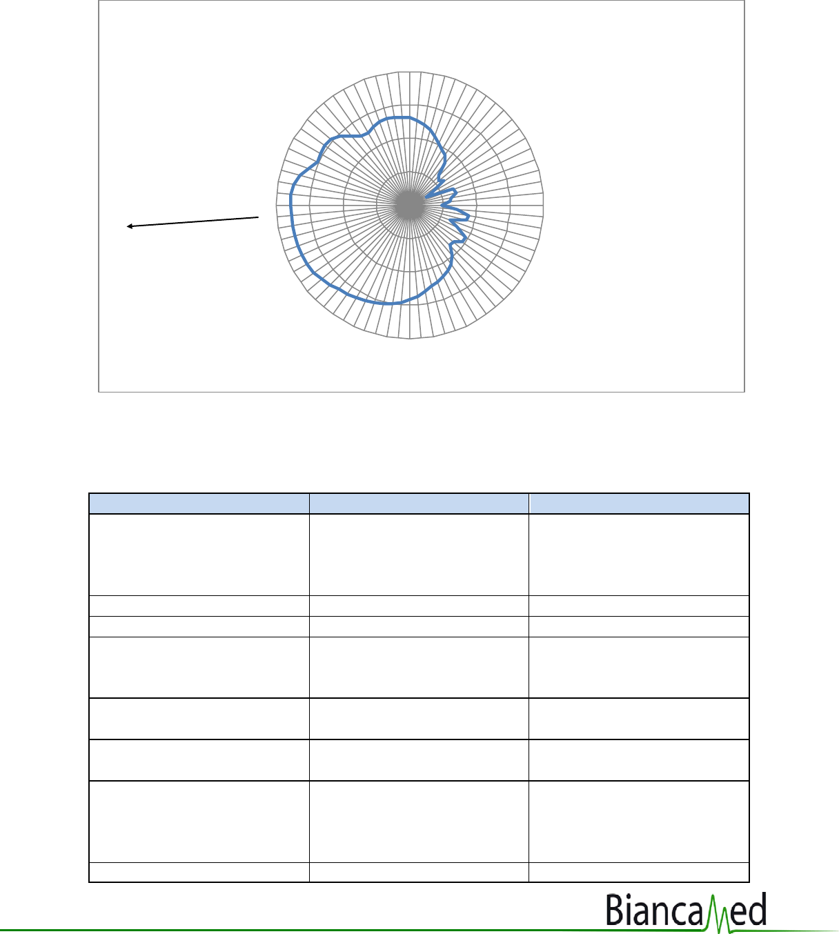
Figure 3b: Elevation Beam Pattern (arrow depicts the line of sight of the antenna, 5 deg below
horizontal in standard mounting)
Electrical Specifications
Parameter
Value
Remarks
Input voltage +4.5 to 12 VDC Prefer 5 to 6 Vdc to reduce
power dissipation on the
sensor board. See notes 1 & 2
below.
Maximum current draw
25 mA
nominal current draw
22mA
Maximum voltage ripple
allowed
40 µVrms /(√ (Hz)) over 10 Hz
to 100 KHz bandwidth
Avoid any noise peak around
5 kHz (close to IF in the
sensor)
Maximum supply voltage
allowed
12 Vdc
Minimum tolerable supply
voltage
+4.5 Vdc
Reference Voltage 1.25 Vdc Provided back to
motherboa rd from the sensor
as analogue zero for ADC
conversion
Reference Voltage line output 1 kOhm
-30
-20
-10
0
10
-175
-170
-165
-160
-155
-150
-145
-140
-135
-130
-125
-120
-115
-110
-105
-100
-95
-90
-85
-80
-75
-70
-65
-60
-55
-50
-45
-40
-35
-30
-25
-20
-15
-10
-5
0
5
10
15
20
25
30
35
40
45
50
55
60
65
70
75
80
85
90
95
100
105
110
115
120
125
130
135
140
145
150
155
160
165
170
175
180
10.525 GHz combined polarisation for elevation
Page 7
Parameter Value Remarks
impedance
Sensor start time before data
is available
n/a Largely dependent upon
software analysis algorithms.
Sensor itself requires <5s
before supplying a stable data
stream.
Connector
Hirose 10-Way 2mm Pitch
Header Connector
•
Note 1: If the OEM motherboard has a regulator that is dedicated to the sensor alone, then
a low loss linear regulator would be suitable as the dedicated supply. The output voltage to
the sensor should be in the region 5 to 6VDC to limit the power dissipation on the sensor
PCB. An example suitable regulator is LM78L05.
Note 2: If supplying a number of sub-assemblies (eg sensor and clock), then a switched-
mode power supply can be used, but the individual sub-assemblies should be wired in “star”
formation so that noise generated on the power line by one sub-assembly does not affect
the sensor sub-assembly. If that is a possible design solution, then BiancaMed could
provide some advice on suitable SMPS and attendant circuitry. Though, the inherent
stability and isolation that a dedicated power supply provides is much preferred.
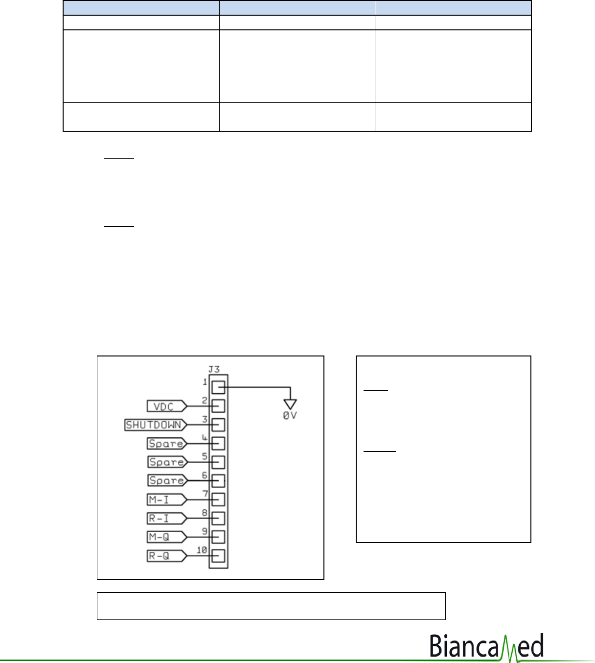
Analogue Sensor Data
Where:
Input:
VDC = +4.5 to +12 VDC
Shutdown = active low, connect to
pin 2 to enable sensor
Output:
M-I= Movement I channel data
R-I= Respiration I channel data
M-Q= Movement Q channel data
R-Q= Respiration Q channel data
Fi gure 4: Pin out of Connector
Note: Changes to pins 4, 5 & 6: no longer used, to be left floating

Page 8
Parameter
Value
Remarks
Movement I & Q Channel See ADC below
Signal bandwidth
50 mHz – 8 Hz
DC offset voltage
1.25 Vdc
Reference voltage provided
within the sensor to centre
the analogue signal around
1.25Vdc
Voltage range
0 – 2.5 Vdc
Noise
<8 mV
rms
R
I
&
Q
Channels
Not used in this
implementation
It is recommended that pins
4, 5, 6, 8 & 10, which are not
used in this implementation,
are left unconnected. If, for
production reasons, a full 10-
way ribbon cable is used, then
pins 4, 5, 6, 8 & 10 should be
terminated at the host
motherboa rd and left floating,
not tied to ground.
Buffering
The sensor module output
pins 5, 7 & 9 must be followed
by additional levels of
buffering and isolation >30dB
before interfacing with a
user’s A/D circuitry
See figure 5 below for
examples
Analogue to Digital
conversion (ADC) requirement
The analogue signal is to be
digitised by the OEM
mothe rboa rd at a rate of 64
samples per second (sps),
with 10 to 12 bit precision.
Post ADC, the sample rate is
to be down sampled to 16 sps
by averaging.
The 64 sps is to avoid Nyquist
aliasing on the source signal
(8Hz bandwidth). Down
sampling then reduces the
memory overhead for data
buffering by the OEM
motherboa rd. Example down
sampling routine is available
from BiancaMed
Page 9
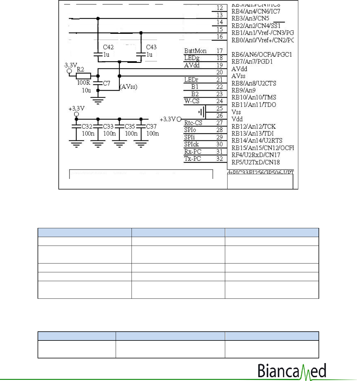
Figure 5: Example of Buffering of Sensor Pins
Environmental Specifications
Parameter Value Remarks
Operating Temperature Range
+15 to +35 deg C
To conform to IEC60065
Operating Humidity Range
30 to 75% RH (non
condensing)
To conform to IEC60065
Storage Temperature range
-20 to +60C
Storage Humidity Range
20 to 95 RH (non-condensing)
IP value Not Applicable IP value provided by OEM
enclosure
Parts & Materials
Test Parameter
Standard no/name
Remarks
Chemicals used in
manufacture
RoHS
Only Lead-free solder used in
PCBA
M-I
M-Q
V ref
From pin:
5
7
9
Edge of MCU

Page 10
Test Parameter Standard no/name Remarks
Chemicals/materials
incorporated into
product
RoHS, WEEE directive
Testing Standards/Conformance to Collateral/
International Standards
Test Parameter
Standard no/name
Remarks
Environmental test of
packaged item
IEC60065
BM11 tested in a
representative enclosure, but
the OEM is responsible for
confirming the compliance in
the OEM enclosure
Electrical safety test IEC60065 BM11 tested in a
representative enclosure, but
the OEM is responsible for
confirming the compliance in
the OEM enclosure
Electro Static Discharge
IEC60601-1-2; EN61000-4-2
BM11 tested in a
representative enclosure, but
the OEM is responsible for
confirming the compliance in
the OEM enclosure
EMC – Radiation emitted
by the BM11
IEC60601-1-2, ETSI EN 300 440-1,
FCC part 15.245
EMC - Susceptibility to
external radiation
IEC60601-1-2 BM11 tested in a
representative enclosure, but
the OEM is responsible for
confirming the compliance in
the OEM enclosure
Device life 5 years by component analysis
Radio Standards
R&TTE Directive 1999/5/EC, FCC
part 15.245, ARIB-std T73v1.1
Audio & video
equipment safety
requi rements
IEC60065
The sensor’s conformance to the
relevant parts of IEC60065 is
satisfied by the IEC60601 tests, a
table of compliance is available
from Bi ancaMed

Page 11
Module Mounting & Product Integration Considerations
• The sensor module consists of a broadside pyramidal horn reflector antenna with a
planar monopole feed. The module is encased in a “hard to access” plastic housing.
• Ideally, the BM11 sensor module would be positioned with no other components within
5 cm, to prevent the influence of other components on the RF tuning.
• It is recommended that OEMs liaise with BiancaMed during the preliminary design of
the product enclosure to ensure the best positioning of the components within the
product. The following design guidelines should be considered:
o The antenna should not have any metallic object in its line of sight (the full cone
angle as specified above).
o There should be 5 to 10mm air gap between the mouth of the antenna and the
enclosure skin.
o The order of preference for the enclosure skin in the way of the antenna is:
Nothing or a totally RF transparent material, eg speaker cloth.
A planar surface of plastic.
A curved surface of plastic, with no reinforcing ribs.
OEMs should provide BiancaMed with an example of the intended product
enclosure at the preliminary design stage. BiancaMed can then test the effects
of the enclosure design on the sensor for shift in centre frequency or beam
modification.
• No moving parts with an oscillating frequency below 10 Hz should exist within the
product’s housing. Any internal movement may be detected by the BM11 sensor and
thus lead to measurement inaccuracies.
Interference from Internal Wireless Devices
Other RF devices within the enclosure have the potential to interfere with the BM11 sensor;
such effects will depend upon operating frequency, radiated power and antenna position.
BiancaMed should be consulted if it is intended to incorporate other RF devices within, or in
close proximity to the product.

Page 12
Information for OEM User Leaflet & Labeling
The following items are provided for OEMs to include in the user leaflets of products that incorporate
the BiancaMed BM11 Sensor.
The items are categorised as Mandatory and Information.
• Mandatory items are required by regulatory authorities to be included in device documentation.
• The Information items are for guidance and can be altered in tone and language to suit the
house style.
It is recommended that the draft device labels and user information leaflet are reviewed by BiancaMed
to ensure their accuracy and regulatory compliance.
Mandatory
Device Label:
(For US Market)
This device complies with Part 15 of the FCC Rules. Operation is subject to the following two conditions:
(1) this device may not cause harmful interference, and (2) this device must accept any interference
received, including interference that may cause undesired operation.
The final end product must be labeled in a visible area with the following:
“Contains TX FCC ID: YAKBM11” or “Contains FCC ID: YAKBM11”.FCC ID: YAKBM11
User Leaflet:
(For US Market)
This equipment has been tested and found to comply with the limits for a Class B digital device,
pursuant to Part 15 of the FCC Rules. These limits are designed to provide reasonable protection
against harmful interference in a residential installation. This equipment generates uses and can
radiate radio frequency energy and, if not installed and used in accordance with the instructions,
may cause harmful interference to radio communications. However, there is no guarantee that
interference will not occur in a particular installation. If this equipment does cause harmful
interference to radio or television reception, which can be determined by turning the equipment off
and on, the user is encouraged to try to correct the interference by one of the following measures:
- Reorient or relocate the receiving antenna.
- Increase the separation between the equipment and receiver.
- Connect the equipment into an outlet on a circuit different from that to which the receiver is
connected.

Page 13
- Consult the dealer or an experienced radio/TV technician for help.
This device complies with Part 15 of the FCC Rules.
Operation is subject to the following two conditions: (1) This device may not cause harmful
interference, and (2) this device must accept any interference received, including interference that
may cause undesired operation.
FCC Caution: Any changes or modifications not expressly approved by “OEM name” could void the
user's authority to operate this equipment.
Note for OEM:
This transmitter module is authorized to be used in other devices only by OEM further transmitter
testing will not be required. However, the OEM integrator is still responsible for testing their end-
product for any additional compliance requirements required with this module installed (for
example, digital device emissions, PC peripheral requirements, etc.).
The OEM integrator has to be aware not to provide information to the end user regarding how to
install or remove this RF module in the user manual of the end product.
Information
Device Information
The non-contact sensor is a very low power Radio Frequency (RF) emitter. The RF power levels are
much less than the BlueTooth on your mobile/cell phone and a WLAN router. The sensor has a
maximum range of 1.5m and is designed to measure the breathing and body movement of an adult
within range. If there are 2 persons in the bed, the sensor is will measure the parameters of the nearer
person.
Device Placement
The product should be placed on a bedside table on the same side of the bed as the user. The height of
the bedside table should ensure that there is a clear line of sight between the sensor and your upper
chest when you are lying on the bed. This is typically a table top height of level with the mattress to
around 6” (15cm) above the mattress. Do not place the product so that it has to “look” through the
mattress at you: the springs in the mattress are likely to disrupt the RF beam. The product should be
placed on the bedside table such that it is within easy arm’s reach of your normal sleeping position.
Tips for initial setup:
• Place the product on your bedside table as outlined above.
• Angle the product so that the screen is at an easy reading angle when you are lying down, and
that the sensor (or front of the product) is aimed approximately at the top of your chest when in
your normal sleeping position.
• Run the application with the live breathing display active.

Page 14
• Lie on the bed in your normal sleeping position. After approximately 30 seconds, a breathing
rate should be displayed. Continue to breath in a normal and steady rate, the displayed
breathing rate should stabilise after approximately 1 minute.
• If you move, the breathing rate display should be suspended whilst you are moving and then
return approximately 15 seconds after you cease moving. Small movements are ignored.
• If you get any periods of “absent” indicated during your test, the sensor is having difficulty
locking on to you. If this happens, re-position the product so that there is a clear line of sight to
your upper chest area, and if necessary, bring the product a bit closer.
Device Specifications
Parameter
Value
Remarks
Centre frequency
10.525 GHz
+/- 10MHz
Antenna Beam width
50 to 60 deg
ie 25 to 30 deg either side of
direct line of sight
Typical breathing
detection range
1.5m
Target aspect not important, ie
can be sitting, lying down on
back/side/front