Resolution RE508X RE508X - Hardwire to Wireless Translator User Manual
Resolution Products, Inc. RE508X - Hardwire to Wireless Translator
User Manual
Installation Guide: RE508X Hardwire to Wireless Translator™
• Selectable wireless panel compatibility
• Rechargeable backup battery
• Accepts any existing hardwire zone type
• Automatic zone polarity and end of line detection
• Battery backed 12VDC output for powered zones
• Cover tamper
• Certied to UL1023 and ULC1023
PANEL ENROLLMENT (For full zone enrollment instructions, refer to Advanced Setup, step 3)
A Enroll Translator into Panel.
• Trip the translator tamper to enroll the translator into the panel (For Honeywell® and 2GIG® panels select loop 1).
-or-
• Enter translator ID into panel. The translator’s base ID is printed on the bar code label and ends with a 0.
B Enroll Zones into panel (not required for Cryptix® Installations)
• With the cover open, trip each zone to enroll into to the panel (For Honeywell® and 2GIG® panels select loop 1).
-or-
• Enter ID into panel. For non-powered zones, the zone ID is the translator’s base ID with the last digit replaced with zone
number 1-8.
Features
FINISH
A Close the cover. Test and verify proper operation of the sensors at the panel.
B Cut the lock wire to lock the translator (For more information on locking, refer to Advanced Setup, step 4).
C Secure cover with screw.
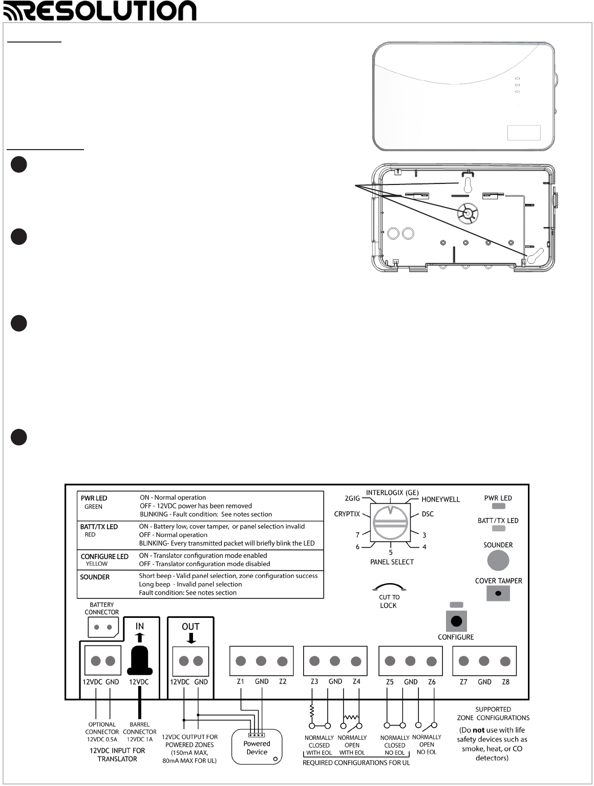
WIRING DIAGRAM
Wall mounting
screw locations
MOUNT AND WIRE
A Select a mounting position and location.
B Wire the zones.
C Connect 12VDC output to powered zones, if any.
D Connect the power supply to the translator.
• Ensure the translator cover is open before power-up.
1
2
3
4
Quick Setup
TRANSLATOR CONFIGURATION
A Select the brand of panel that the translator must
talk to using the “PANEL SELECT” knob.
B Congure Zones.
• No zone conguration is necessary for installations with normally
closed zones that don’t require tamper detection.
• Installations with other zone types: Refer to the Advanced Setup, step 2.
(Mounting hardware not included. Use two
#4 or # 6 screws for mounting )
INSTALLATION VIDEOS and PRODUCT INFORMATION: http://resolutionproducts.com/products/translators-repeaters/universal-translator/

Advanced Setup
MOUNT AND WIRE
A Select a mounting position and location.
• Mount the translator at least 5 feet from the Control Panel’s
receiver.
• Do NOT mount the translator in a metal can or on a metal
surface.
• Verify adequate RF signal strength at the panel before
permanently mounting.
B Wire the zones.
• End of line resistors are not required.
• Normally closed zones may have end of line resistors up to
15k ohms.
• Normally open zones may have end of line resistors down
to 750 ohms.
• Do NOT put power on zone input terminals.
• The plastic loops along the bottom edge of the translator
housing may be used to secure the zone wiring with tie
wraps.
C Connect 12VDC output to powered zones, if any.
• 12VDC output of the translator must be used to power any
powered zones. Do NOT use an external power supply to
power zones.
D Connect the power supply to the translator using either the
supplied barrel connector or ying leads.
• Ensure the translator cover is open before power-up.
• Rotate the barrel plug down to the right so the wires exit the
enclosure through the strain relief area.
• Ensure the backup battery leads are plugged into the
translator.
• The power transformer must be plugged into a non-switched
outlet.
• In the United States, the transformer must be secured to
an outlet.
• In Canada, the transformer must NOT be secured to an
outlet.
TRANSLATOR CONFIGURATION
A Select the brand of panel that the translator must talk to
using the “PANEL SELECT” knob.
B Congure Zones:
• Zone conguration is not necessary for installations with
normally closed zones that don’t require tamper detection.
Installations with other zone types: Follow steps below.
a) Put all zones into normal (non-alarm) state.
b) Press and release the CONFIGURE button to enter
translator conguration mode. The yellow LED will turn on
when translator conguration mode is entered. Zone
tamper will now be detected for the zones, and will be
transmitted to the panel as “alarm.”
c) If you want zone tamper to be transmitted to the panel as
“tamper” instead of “alarm,” cycle each zone to alarm and
back to normal while translator is in conguration mode.
The translator will beep to conrm as zones are cycled.
d) Press CONFIGURE button to exit translator conguration
mode. The yellow LED will turn off when the translator
conguration mode is exited.
• Normally closed zones can be cycled at the sensor, or by a
break-and-make at the connection to the translator.
• Normally open zones can be cycled at the sensor, or by a
shorting across the connection to the translator.
• Conguration mode ends automatically when the cover
is closed or 10 minutes after the last action.
TRANSLATOR CONFIGURATION (continued)
• When re-entering translator conguration mode, zones must be
in their normal state. However, previously programmed
settings are retained for each zone. There is no need to re-
congure every zone if the intention is to modify a subset of
the zones.
• Conguration mode is locked out 24 hours after power-up.
To re-enable conguration mode, the translator must be power-
cycled by removing both the 12VDC input power and backup
battery for at least 5 seconds.
PANEL ENROLLMENT
A Enroll Translator into Panel:
• Trip the cover tamper to enroll the translator into the panel.
-or-
• Enter ID into panel. The translator’s base ID is printed on
the bar code label and ends with a 0.
(For Honeywell® and 2GIG® panels, select loop 1)
B Enroll Zones into panel (non-Cryptix Installations):
• With the cover open, trip each zone to send an enrollable
zone transmission to the panel.
-or-
• Enter ID into panel. For non-powered zones, the zone ID is
the translator’s base ID with the last digit replaced with
zone number 1-8.
C Finish setup of each zone at the panel. Below are guidelines
on how to enroll the translator and zones into your panel.
Refer to the panel installation manual for complete panel
instructions.
Cryptix ®
Translator and Zone enrollment:
Press the enroll button on the panel.
Trip the translator cover tamper to enroll the translator.
Finish setup of each zone at the online portal.
Interlogix ® (formerly GE ®)
Translator enrollment:
Enter Learn Sensor mode.
At the Trip Sensor prompt: Trip the translator cover tamper
to enroll the translator into the panel. Select Group based
on how you want translator tamper to be handled by the
panel. Below are recommended groups:
• Group 13 - Instant perimeter
• Group 23 - Local instant auxiliary
Zone enrollment:
Enter Learn Sensor mode.
At the Trip Sensor prompt: With the translator cover open,
trip each zone to enroll it.
• For the rst 24 hours after powerup, all GE zone trips
will transmit a temporary tamper for enrollment if the
translator cover is open.
Honeywell ®
Translator enrollment:
Enter Programming mode.
Zone Type: 8 (24 hour Aux).
Input Type: 3 (Supervised RF).
When prompted, trip the translator cover tamper or enter
the ID number on the unit to enroll serial number.
Change the zone to loop 1.
Zone enrollment:
Enter Programming mode.
Set up the zone for the desired behavior.
When prompted, trip the zone.
Ensure loop 1 is selected.
1
2
3
2
PANEL ENROLLMENT (continued)
DSC ®
Translator enrollment:
Enter Wireless Enrollment mode.
Trip the translator cover tamper to enroll the translator.
Zone Type: 03
• For the rst 24 hours after power-up, all translator
tamper trips will send a temporary “open” for
enrollment purposes.
Zone enrollment:
Enter Wireless Enrollment Mode.
Trip each zone to initiate enrollment.
Conrm ESN, Enter Zone #, and Zone Type.
Setup the zone for the desired behavior.
2GIG ®
Translator enrollment:
Enter RF enrollment mode
Sensor Type: (01) exit entry
Equipment Type: (1) contact
Equipment Code: (0862) DW10-345
At “Enter RF Serial Number”
• Press SHIFT, Learn, then trip sensor
-or-
• Enter translator’s base ID number printed on the unit
Equipment Age: (0) new
Loop Number: (1)
Zone enrollment:
Enter RF enrollment mode.
Setup the zone for the desired behavior.
At “Enter RF Serial Number”
• Press SHIFT, Learn, then trip sensor
-or-
• Enter zone ID number (translator’s base ID with the
last digit replaced with zone number 1-8).
Equipment Age: (0) new
Loop Number: (1)
Qolsys ®
• Qolsys IQ panel uses Interlogix 319.5MHz protocol.
• DSC Touch panel made by Qolsys uses DSC 433.92MHz
protocol.
FINISH
A Close the cover. Test and verify proper operation at the
panel. Ensure all zone alarms are reported properly to the
central station.
B Translator Locking: Locking the translator locks all
translator conguration settings and provides takeover
protection.
a) Ensure all zones are functioning as desired.
b) Carefully review the effects of translator locking before
proceeding:
• Translator can not be factory defaulted.
• Existing zone congurations can not be changed.
• Panel selection can not be changed.
• Translator LOCKING CAN NOT BE UNDONE.
c) Open the translator cover and cut the lock wire. The green
and red LED will ash, and the sounder will beep to
conrm.
C With the cover closed, insert the cover securing screw into the
screw hole near the cover latch.
Notes
ZONES
• Powered zones have a 60 second lockout after power-up.
• Powered zones are turned off when the battery gets low.
• Powered zones have a four hour minimum battery backup after
power failure.
• Non-powered zones have 24-hours minimum battery backup
regardless of powered zones.
• All zone status is sent out within a couple minutes of the cover
being closed.
• If the translator loses both AC and battery backup power, zone
conguration data is retained.
• Low battery, tamper, and supervisory signals are reported by the
translator on its base zone with ID ending in “0”.
• Zone ID’s generally end in 1-8. This is NOT true for Honeywell®
and powered zones.
• Low battery signals from the translator are suppressed in the rst
24 hours after power-up. However, a missing battery condition is
reported right away.
FAULT CONDITIONS
• 12VDC output fault: Flashes and beeps every 10 seconds on the
green LED and sounder.
• 12VDC input overvoltage fault: Continually ashes and beeps on
the green LED and sounder.
• 12VDC input removed fault: Green LED turns off and the
sounder makes a long beep.
FACTORY DEFAULT
• To return the translator to a factory default condition, press and
hold the congure button. After a couple seconds, the sounder
will start beeping rapidly. Continue holding the button until the
sounder stops beeping.
• Factory default is not possible if the translator is locked.
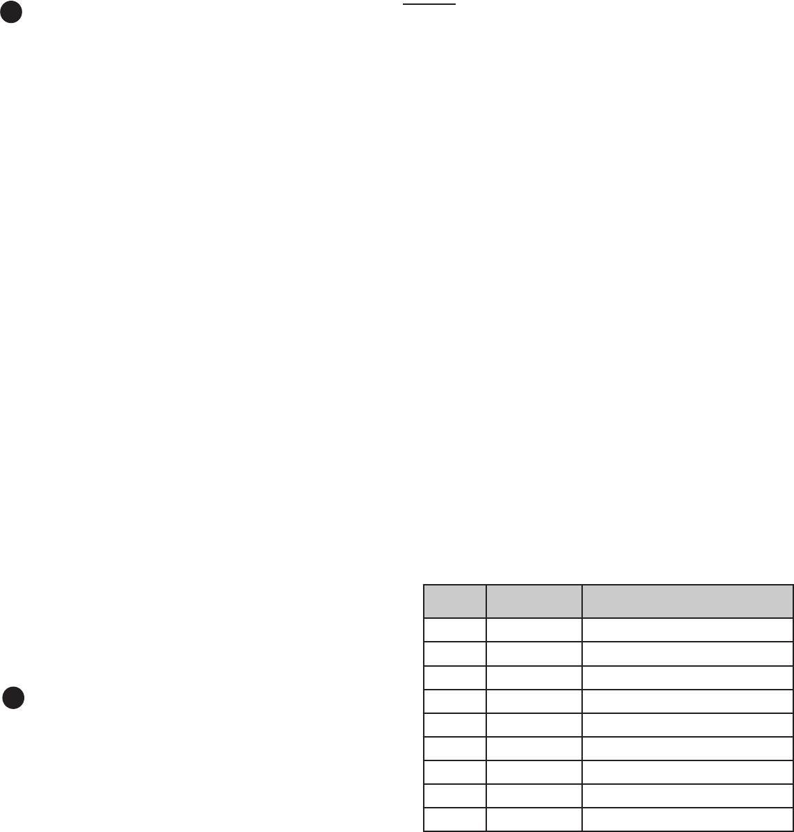
ZONE TABLE
3
4
ZONE # SERIAL # DESCRIPTION
0 Translator Base
1
2
3
4
5
6
7
8
“GE”, “INTERLOGIX”, “HONEYWELL”, “DSC”, “2GIG”, AND “QOLSYS” ARE TRADEMARKS OWNED BY
GENERAL ELECTRIC COMPANY, UNITED TECHNOLOGIES ELECTRONIC CONTROLS INC.,
HONEYWELL INTERNATIONAL INC., TYCO SAFETY PRODUCTS CANADA LTD, NORTEK SECURITY &
CONTROL LLC, AND TYCO SAFETY PRODUCTS CANADA LTD, RESPECTIVELY.
RESOLUTION PRODUCTS, INC. PRODUCTS WILL FUNCTION WITH ONE OF EITHER INTERLOGIX (FOR-
MERLY GE), HONEYWELL, DSC, 2GIG OR QOLSYS SYSTEMS. HOWEVER, NO RESOLUTION PRODUCT IS
PRODUCED BY, ENDORSED BY, NOR IS OFFICIALLY ASSOCIATED WITH INTERLOGIX (FORMERLY GE),
HONEYWELL, DSC, 2GIG OR QOLSYS. RESOLUTION RECOMMENDS VERIFYING PROPER ENROLLMENT
AND OPERATION, PER CONTROL PANEL INSTALLATION INSTRUCTIONS, AT INSTALLATION.
WARRANTY
RESOLUTION PRODUCTS, INC. WILL REPLACE PRODUCTS THAT ARE DEFECTIVE IN THEIR FIRST FIVE
(5) YEARS.
FCC NOTICE
THIS DEVICE COMPLIES WITH PART 15 OF THE FCC RULES. OPERATION IS SUBJECT TO THE
FOLLOWING TWO CONDITIONS:
(1) THIS DEVICE MAY NOT CAUSE HARMFUL INTERFERENCE.
(2) THIS DEVICE MUST ACCEPT ANY INTERFERENCE THAT MAY BE RECEIVED, INCLUDING
INTERFERENCE THAT MAY CAUSE UNDESIRED OPERATION.
CHANGES OR MODIFICATIONS NOT EXPRESSLY APPROVED BY RESOLUTION PRODUCTS, INC. COULD
VOID THE USER’S AUTHORITY TO OPERATE THIS EQUIPMENT.
FCC ID: U5X-RE508X
IC NOTICE
THIS DEVICE COMPLIES WITH INDUSTRY CANADA LICENSE-EXEMPT RSS STANDARD(S).
OPERATION IS SUBJECT TO THE FOLLOWING TWO CONDITIONS:
(1) THIS DEVICE MAY NOT CAUSE INTERFERENCE, AND
(2) THIS DEVICE MUST ACCEPT ANY INTERFERENCE, INCLUDING INTERFERENCE THAT MAY
CAUSE UNDESIRED OPERATION OF THE DEVICE.
LE PRÉSENT APPAREIL EST CONFORME AUX CNR D’INDUSTRIE CANADA APPLICABLES AUX APPAREILS
RADIO EXEMPTS DE LICENCE. L’EXPLOITATION EST AUTORISÉE AUX DEUX CONDITIONS SUIVANTES :
(1) L’APPAREIL NE DOIT PAS PRODUIRE DE BROUILLAGE, ET
(2) L’UTILISATEUR DE L’APPAREIL DOIT ACCEPTER TOUT BROUILLAGE RADIOÉLECTRIQUE SUBI,
MÊME SI LE BROUILLAGE EST SUSCEPTIBLE D’EN COMPROMETTRE LE FONCTIONNEMENT.
IC: 8310A-RE508X
Notices
Manual: 47-0013-00 REV X6
Date: 04-Feb-16
24-Hour Tech Support Line: (877)260-5578
www.ResolutionProducts.com
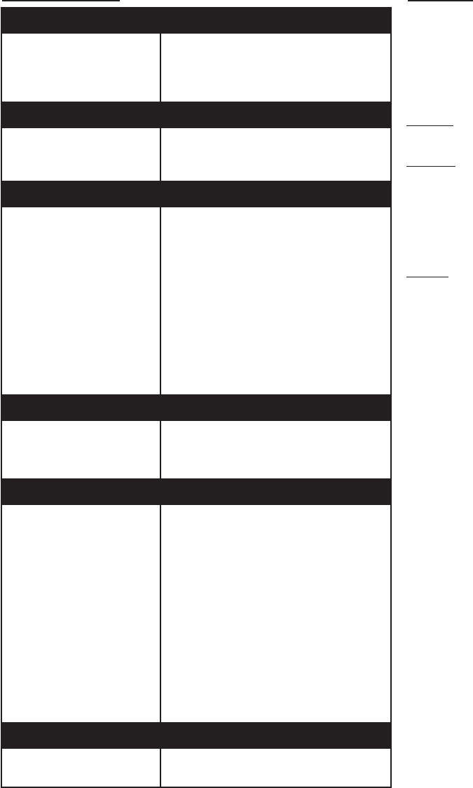
Specications
Specications subject to change without notice.
This product is NOT for use with life safety devices, such
as Smoke, Heat, or CO detectors.
PHYSICAL
Housing Dimensions
Weight with Battery
Tamper Activation
Mounting Screws
8.5 x 5.0 x 1.2 inches
10.4 Ounces
Cover Opening
#4 of #6
ENVIRONMENTAL
Operating Temperature
Storage Temperature
Maximum Humidity
32 to 120˚F (0 to 49˚C)
-4 to 86˚F (-20 to 30˚C)
85% relative humidity, non-condensing
POWER
12VDC Output
Power Transformer
Input
Output
Part Number
Battery
Specications
Part Number
Trickle Charge
Fast Charge
10.2VDC to 13VDC, 150mA Max
(80mA Max for UL installations)
100-240VAC 50/60Hz 0.5A
12VDC 1A
RE012-6
6VDC 800mAh NiMH
34-0012-00
8mA
32mA
WIRELESS RADIO
RF Frequency
Compatibility
319.5MHz, 345MHz, 433.92MHz
Cryptix®, Interlogix® (formerly GE®),
Honeywell®, DSC®, 2GIG®, Qolsys®
ZONES
Supported Types
Powered Zones
Non-Powered Zones
Battery Backup
Powered Zones
Non-Powered Zones
Zone End of Line Resistor
NC - No Tamper Detect
NC - Tamper Detect
NO - No Tamper Detect
NO - Tamper Detect
Zone Wire Length
Zone Wire Gauge
4-wire devices only
NC (Normal closed) or NO (Normal open)
4 hours minimum at 80mA
24 hours minimum
None (short)
750 ohm to 15k ohm
None (open)
750 ohm to 15k ohm
1000 feet max
22 AWG min
CERTIFICATIONS
ETL Listings
Other
UL 1023, ORD-C1023-1974
FCC, IC