Resolution RE524X RE524X - Wireless to Wireless Translator User Manual
Resolution Products, Inc. RE524X - Wireless to Wireless Translator
UserManual.wiki
>
Resolution
>
RE524X User Manual
User Manual
Navigation menu
Upload a User Manual
Namespaces
Wiki Guide
HTML
PDF
Info
Views
User Manual
Discussion / Help
Navigation
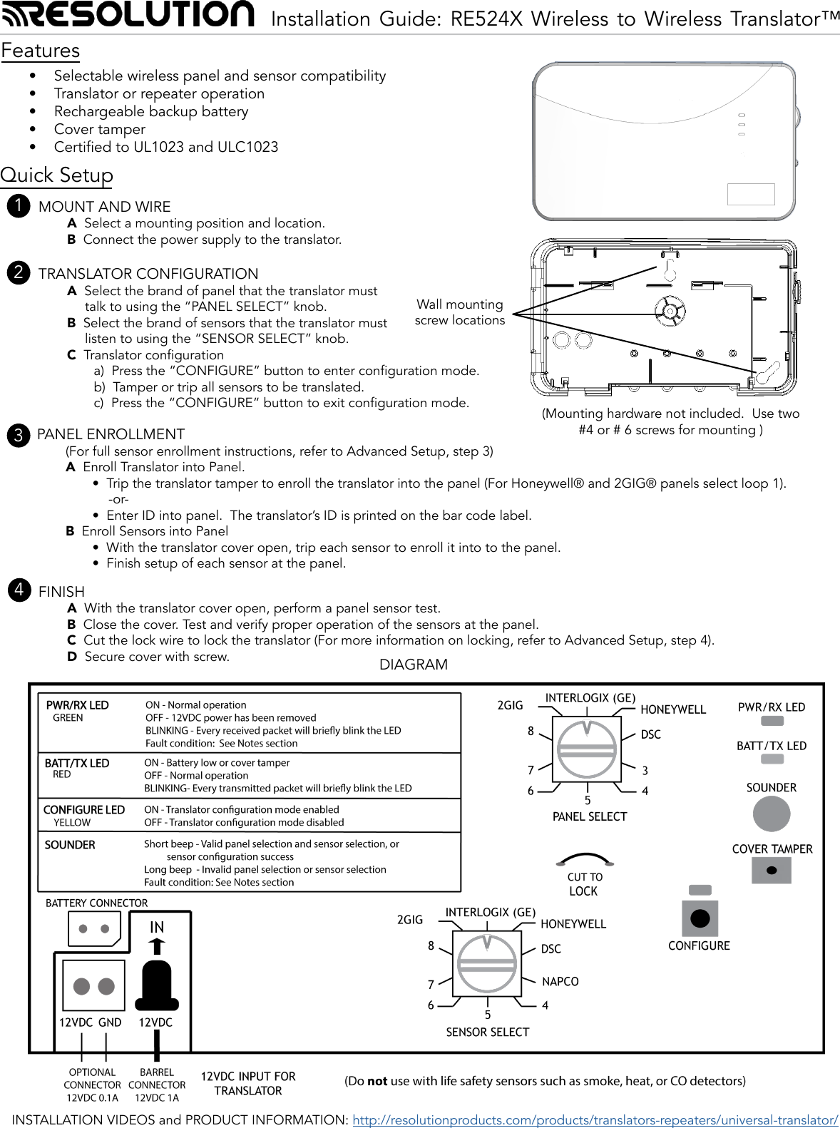
![Advanced SetupMOUNT AND WIREA Select a mounting position and location.• Mount the translator at least 5 feet from the Control Panel’s receiver. • Do NOT mount the translator in a metal can or on a metal surface.• Verify adequate RF signal strength at the panel before permanently mounting.B Connect the power supply to the translator using either the supplied barrel connector or ying leads. • Rotate the barrel plug down to the right so the wires exit the enclosure through the strain relief area.• Ensure the backup battery connector is plugged into the translator.• The power transformer must be plugged into a non-switched outlet.• In the United States, the transformer must be secured toan outlet. • In Canada, the transformer must NOT be secured to the outlet.TRANSLATOR CONFIGURATIONA Select the brand of panel that the translator must talk tousing the “PANEL SELECT” knob.B Select the brand of sensors that the translator must listen tousing the “SENSOR SELECT” knob.C Translator Congurationa) Press and release the CONFIGURE button to entertranslator conguration mode. The yellow LED will turn on when translator conguration mode is entered. b) Tamper or trip all the sensors to be translated. The translator beeps for each sensor that is included in the system.c) Press CONFIGURE button to exit translator congurationmode. The yellow LED will turn off when the translator conguration mode is exited.• Conguration mode ends automatically when the coveris closed or 30 minutes after the last action. • Sensors may be enrolled directly into the panel while in conguration mode. • Conguration mode is locked out 24 hours after power up. To re-enable conguration mode, the translator must be power cycled by removing both 12VDC input power and backup battery for at least 5 seconds.• When re-entering translator conguration mode, previously congured sensors are retained. There is no need to re-congure every sensor if the intention is to add a sensor.• Conguration data is retained even if both the 12VDC input power and battery backup power are lost. • When both the panel and sensor selection knobs are set to the same brand the translator will act as a repeater.PANEL ENROLLMENTA Enroll Translator into Panel:• Trip the cover tamper to enroll the translator into the panel.-or-• Enter ID into panel. The translator’s base ID is printed onthe bar code label. (For Honeywell® and 2GIG® panels, select loop 1)PANEL ENROLLMENT (continued)B Enroll Sensors into panel:• Tamper or trip each sensor to send an enrollable transmission to the panel. • Installations using Interlogix (formerly GE) panels require the translator cover to be open so sensor tamper signals are sent on sensors that do not have a tamper switch.• Finish setup of each sensor at the panel.Below are guidelines on how to enroll the translator and sensors into your panel. Refer to the panel installation manual for complete panel instructions.Interlogix ® (formerly GE ®)Translator enrollment:Enter Learn Sensor mode.At the Trip Sensor prompt: Trip the translator’s cover tamper to enroll the translator into the panel. Select Group 13 instant perimeterSensor enrollment:Enter Learn Sensor mode.At the Trip Sensor prompt: Tamper each sensor to enroll it. If the sensor does not have a tamper switch trip the sensor with translator cover open to enroll it.• For the rst 24 hours after power-up, all Interlogix sensor trips will transmit a temporary tamper for enrollment if the translator cover is open.Set up the sensor for the desired behavior.Honeywell ®Translator enrollment:Enter Programming mode. Zone Type: 3 (Perimeter).Input Type: 3 (Supervised RF).When prompted:• Trip the translator’s cover tamper multiple times.-or- • Enter the translator’s ID number, which is printed on the unit.Change the sensor to loop 1. Sensor enrollment:Enter Programming mode.Set up the sensor for the desired behavior.When prompted, perform the typical Honeywell enrollment sequence.The translator does not support multiple loops on Honewell sensors. Ony one loop may be used.2GIG ®Translator enrollment:Enter RF enrollment modeSensor Type: (03) perimeterEquipment Code: (0862) DW10-345.At “Enter RF Serial Number”:• [press SHIFT, Learn, Trip the translator’s cover tamper].-or-• Enter the translator’s ID number, which is printed on the unit.Equipment Age: (0) newLoop Number: (1)Sensor enrollment:Enter RF enrollment mode.Set up the sensor for the desired behavior.When prompted, perform the typical 2GIG enrollment sequence.12333](https://usermanual.wiki/Resolution/RE524X/User-Guide-2907912-Page-2.png)