Resolution RE920 IP Module User Manual 1 of 2
Resolution Products, Inc. IP Module 1 of 2
Contents
- 1. User manual 1 of 2
- 2. User manual 2 of 2
User manual 1 of 2
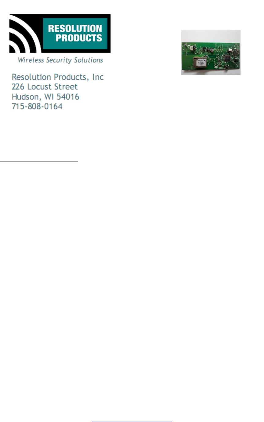
RE920 PA IP Module
Features
•Connects in daughterboard slot of SimonXT panel
•Allows reporting of alarm and status conditions over IP connection
•Allows control of system functions (arming, disarming, etc) over IP
connection
•Allows control of lights and other Zwave devices over IP connection
Key Instructions
•Install RE920 unit in slot at back of panel
•Power up the panel
•Connect ethernet cable
•Connect to configuration software and enter MAC address
•Configure RE920 to correct IP address for reporting
•Configure RE920 to correct IP address for system control
LED Operation
•"L and S" LEDs are normal ethernet LEDs and indicate healthy ethernet
network connection
•"Power" LED lights green when powered and shows heartbeat for
processor functioning correctly
•"Local" LED lights when proper connection to local router established
•"CS" LED lights when connected to Central Station
•"Platform" LED lights when connected to interactive platform website
RE920_IP_Module_Manual.doc
Page 1 of 407-Jan-11
www.ResolutionProducts.com
Specifications
Panel Compatibility: GE/Interlogix SimonXT
External supply: 9-18V DC, at least 100mA.
Current draw: 60mA, normal operation.
PCB dimensions: 1.9 x 4.1 inches
Specifications subject to change without notice.
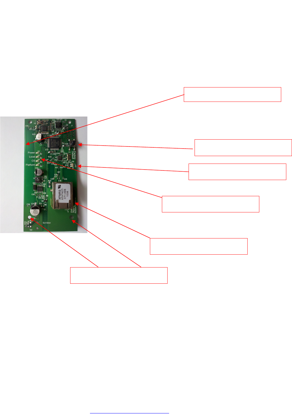
Internal Picture
RE920_IP_Module_Manual.doc
Page 2 of 407-Jan-11
www.ResolutionProducts.com
Ethernet LEDs
Ethernet Connector
Factory Default Switch
Status LEDs
Printed Zwave Antenna
Mounting Holes
OEM Installation Instructions
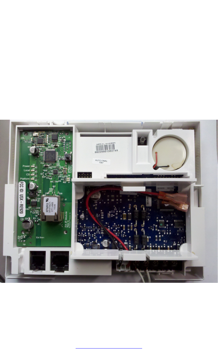
The RE920 module is installed in the SimonXT host as follows:
1. The SimonXT should be powered down.
2. Expose the back of the panel as shown in the following picture.
3. The module is installed in the expansion slot on the left, as shown in the
picture.
4. Unwrap the module from its packaging and carefully slide the module
underneath the plastic tabs at the top of the expansion slot.
5. Gently press down on the bottom of the module so that it engages with
the connector on the panel.
6. Secure the module in place using four screws in the provided holes.
7. Attach ethernet cable to the connector and arrange it so that it exits the
enclosure with out strain.
8. Connect to the module using the configuration IP Address and configure
the module's IP Addresses and other information with the configuration
interface.
RE920_IP_Module_Manual.doc
Page 3 of 407-Jan-11
www.ResolutionProducts.com

Notices
“GE” is a trademark owned by General Electric Company. "Interlogix" is a trademark of UTC.
This Resolution product is not produced by, endorsed by, or officially associated with GE or
UTC. Resolution recommends verifying operation at installation.
This product is only usable with the GE/Interlogix SimonXT alarm panel.
FCC Notice
This device complies with Part 15 of the FCC rules. Operation is subject to the
following two conditions:
This device may not cause harmful interference.
This device must accept any interference that may be received, including
interference that may cause undesired operation.
Changes or modifications not expressly approved by the Resolution Engineering, Inc.
could void the user's authority to operate this equipment.
FCC ID: U5X-RE920
RE920_IP_Module_Manual.doc
Page 4 of 407-Jan-11
www.ResolutionProducts.com