Respironics 1127941BT Wi-Fi and Bluetooth Module User Manual 2ANZ 1127941BT
Respironics, Inc. Wi-Fi and Bluetooth Module 2ANZ 1127941BT
Radio Integration Manual
2ANZ-1127941BT | Module Integration
Respironics Inc. (Philips Respironics)
1001 Murry Ridge Lane
Murrysville PA 15668
Module Integration
This document describes how to integrate the TI WL1831MOD radio module into a final product with a
chip Antenna in a SISO system.
The WL1831MOD is a surface mount Bluetooth and Wi-Fi combo radio module in the WL18XX family
from Texas Instruments. The module data sheet can be found at the manufacturer’s web site below:
http://www.ti.com/wireless-connectivity/simplelink-solutions/wi-fi/products.html
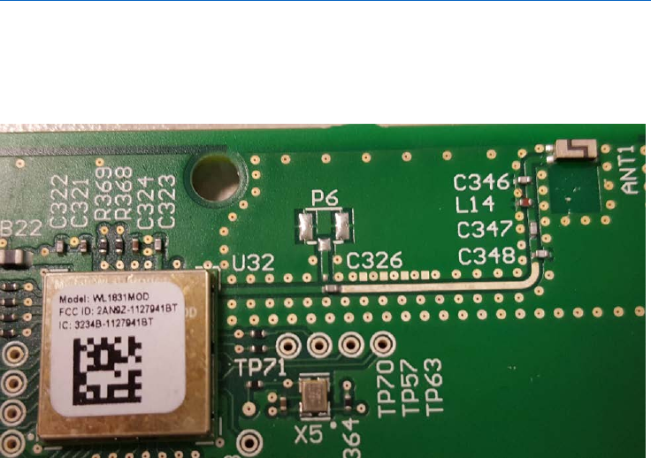
The module is shown below, along with the transmission line connecting it to the matching network and
chip antenna.
The module connects back to the host through multiple interfaces. All of these interfaces operate at a
nominal supply voltage of 1.8V. The pin assignments of these signals are showing in Table 1 and Figure
1.
DC Input Power:
The radio module power is regulated internally by the module. Power is applied to the VBAT_IN
terminals with a voltage in the range of 2.9-4.8V. The I/O voltage of the module is set by applying 1.8V
to the VIO_IN Terminal.
Slow Clock:
The radio requires a 32.768 kHz square wave input at the EXT_32K input terminal of the module.
Bluetooth UART:
The Bluetooth subsystem is controlled via an HCI 4-wire UART interface operating at 1.8V.

2ANZ-1127941BT | Module Integration
Respironics Inc. (Philips Respironics)
1001 Murry Ridge Lane
Murrysville PA 15668
Bluetooth PCM:
The Bluetooth PCM can be used for BT Audio and can operate in either a master or slave configuration.
If they are not used they should be not connected. (NC)
WLAN Host Interface
The WLAN interfaces uses a 4-bit SDIO Interface back to the host operating at 1.8V. The host must
provide PU using a 10-K resistor for all non-CLK SDIO signals.
In order to follow the wakeup/shutdown requirements, the WL_EN (pin number 40) should be
connected to host GPIO. Must be pulled high for WLAN operation. This GPIO should have internal pull-
up allowing the WL18xx pin to remain high on host suspend. In order to enable WOW feature, a pull up
on the line is required during HOST shutdown.
IRQ_WL should be connected to host GPIO. This GPIO should be able to wake the host from suspend,
therefore it's better to always connect the pin (number 14) to the always on domain of the Host. The
IRQ_WL pin serves as interrupt generation from WL18xx to the host.
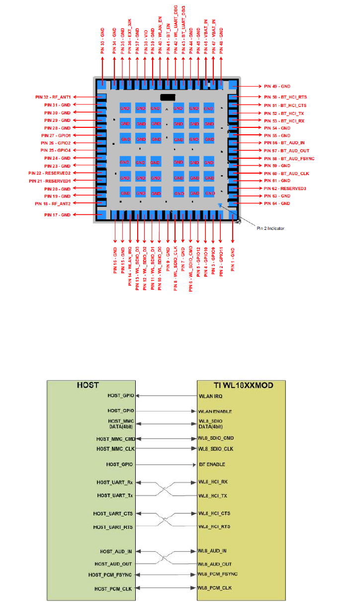
Table 1: Device Pinout
Pin #
Signal
Function
Pin #
Signal
Function
1
GND
33
GND
2
NC
Reserved for future use, NC
34
GND
3
NC
Reserved for future use, NC
35
GND
4
NC
Reserved for future use, NC
36
EXT_32K
Input clock of 32.768 kHz
5
NC
Reserved for future use, NC
37
GND
6
WL_SDIO_CMD_1V8
WLAN SDIO Command
38
VIO_IN
Sets I/O voltage.
7
GND
39
GND
8
WL_SDIO_CLK
WLAN CDIO CLK, must be
driven by host
40
WLAN_EN
Hi = Enable
9
GND
41
BT_EN
Hi = Enable
10
WL_SDIO_CMD_1V8
WLAN SDIO data bit 0
42
WL_UART_DBG
Used for Debug
11
WL_SDIO_D1_1V8
WLAN SDIO data bit 1
43
BT_UART_DBG
Used for Debug
12
WL_SDIO_D2_1V8
WLAN SDIO data bit 2
44
GND
13
WL_SDIO_D3_1V8
WLAN SDIO data bit 3
45
GND
14
WL_IRQ_1V8
WLAN SDIO IRQ
46
VBAT_IN
Power Supply Input: 2.9-4.8V
15
GND
47
VBAT_IN
Power Supply Input: 2.9-4.8V
16
GND
48
GND
17
GND
49
GND
18
RF_ANT2
NC if not used
50
BT_HCI_RTS_1V8
UART RTS to Host
19
GND
51
BT_HCI_CTS_1V8
UART CTS to Host
20
GND
52
BT_HCI_TX_1V8
UART TX to Host

2ANZ-1127941BT | Module Integration
Respironics Inc. (Philips Respironics)
1001 Murry Ridge Lane
Murrysville PA 15668
21
NC
Reserved for future use, NC
53
BT_HCI_RX_1V8
UART RX to Host
22
NC
Reserved for future use, NC
54
GND
23
GND
55
GND
24
GND
56
BT_AUD_IN
BT Audio, NC if not used
25
NC
Reserved for future use, NC
57
BT_AUD_OUT
BT Audio, NC if not used
26
GPIO2
Used for Debug
58
BT_AUD_FSYNC
BT Audio, NC if not used
27
GPIO1
Used for Debug
59
GND
28
GND
60
BT_AUD_CLK
BT Audio, NC if not used
29
GND
61
GND
30
GND
62
NC
Reserved for future use, NC
31
GND
63
GND
32
RF_ANT1
RF Antenna Connection
64
GND
2ANZ-1127941BT | Module Integration
Respironics Inc. (Philips Respironics)
1001 Murry Ridge Lane
Murrysville PA 15668
Figure 1: Device Pinout.
Figure 2: Host Connections
2ANZ-1127941BT | Module Integration
Respironics Inc. (Philips Respironics)
1001 Murry Ridge Lane
Murrysville PA 15668
Antenna Connection:
The antenna is connected to terminal RF_ANT1 on the radio module. The connection between the
antenna and RF_ANT1 should be made with a 50 ohm transmission line. A matching network will be
needed to match the antenna and should be placed right before the antenna input.
Avoid routing any analog or digital signals on the signal layer directly underneath any of the radio,
matching network or antenna. All of the ground pins on the module must be connected to the main PCB.
This device is intended only for OEM integrators under the following conditions:
• The antenna must be installed so that 20 cm is maintained between the antenna and users.
• The transmitter module cannot be co-located with any other transmitter or antenna.
• The radio transmitter can operate only using a chip antenna with a maximum gain of 2.2dBi.
Labeling
If the FCC identification number is not visible when the module is installed inside another device, then
the outside of the device into which the module is installed must also display a label referring to the
enclosed module. This exterior label can use wording such as the following: “Contains Transmitter
Module FCC ID: 2AN9Z-1127941BT” or “Contains 2AN9Z-1127941BT.” Any similar wording that
expresses the same meaning may be used.
2ANZ-1127941BT | Regulatory Compliance
Respironics Inc. (Philips Respironics)
1001 Murry Ridge Lane
Murrysville PA 15668
Regulatory Compliance
This device complies with part 15 of the FCC Rules. Operation is subject to the following two conditions:
(1) This device may not cause harmful interference, and (2) This device must accept any interference
received, including interference that may cause undesired operation.
This equipment has been tested and found to comply with the limits for a Class B digital device,
pursuant to Part 15 of the FCC Rules. These limits are designed to provide reasonable protection against
harmful interference in a residential installation. This equipment generates, uses, and can radiate radio
frequency energy and, if not installed and used in accordance with the instructions, may cause harmful
interference to radio communications.
However, there is no guarantee that interference will not occur in a particular installation. If this
equipment does cause harmful interference to radio, TV reception, or other devices which can be
determined by turning the equipment on and off, the user is encouraged to try to correct the
interference by one or more of the following measures:
Reorient or relocate the receiving antenna (on the radio, TV, or other device).
Increase the separation between the equipment and receiver.
Connect the equipment into an outlet on a circuit different from that to which the receiver is connected.
Consult the dealer of the device for help.
Any changes or modifications made to the device that are not expressly approved by Respironics may
void the user’s authority to operate the equipment.
This device is intended only for OEM integrators under the following conditions:
• The antenna must be installed so that 20 cm is maintained between the antenna and users.
• The transmitter module cannot be co-located with any other transmitter or antenna.
• The radio transmitter can operate only using a chip antenna with a maximum gain of 2.2dBi.