Rexon GDR02 Garage Door Opener User Manual
Rexon Industrial Corp. Ltd. Garage Door Opener Users Manual
UserManual.wiki
>
Rexon
>
GDR02 User Manual
Users Manual
Navigation menu
Upload a User Manual
Namespaces
Wiki Guide
HTML
PDF
Info
Views
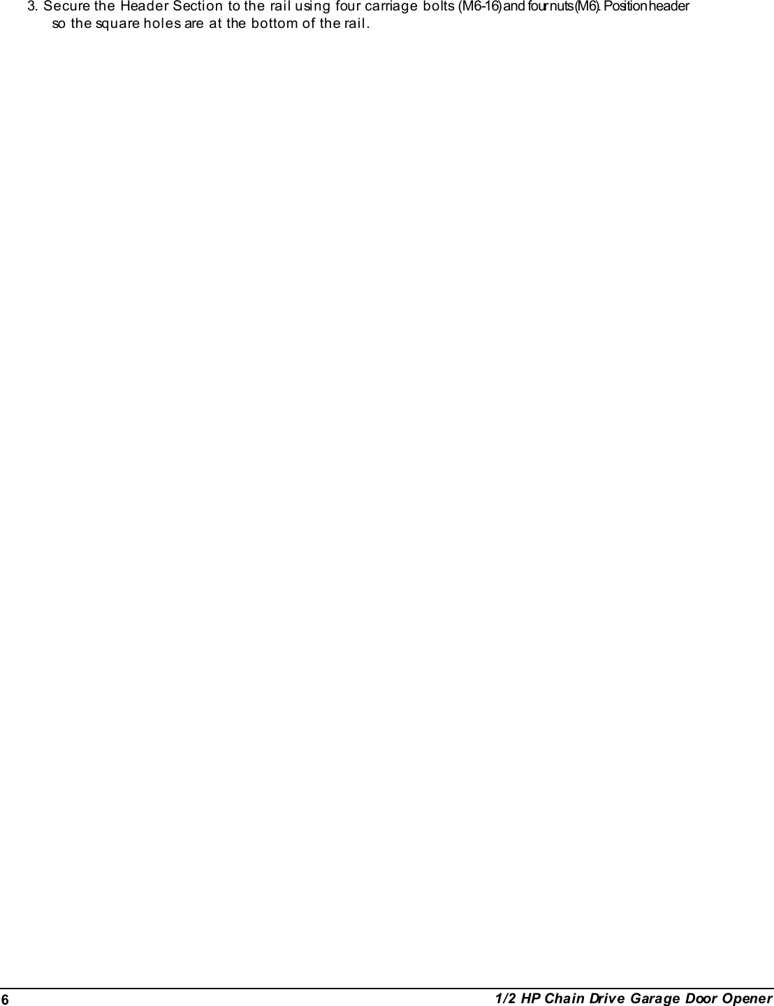
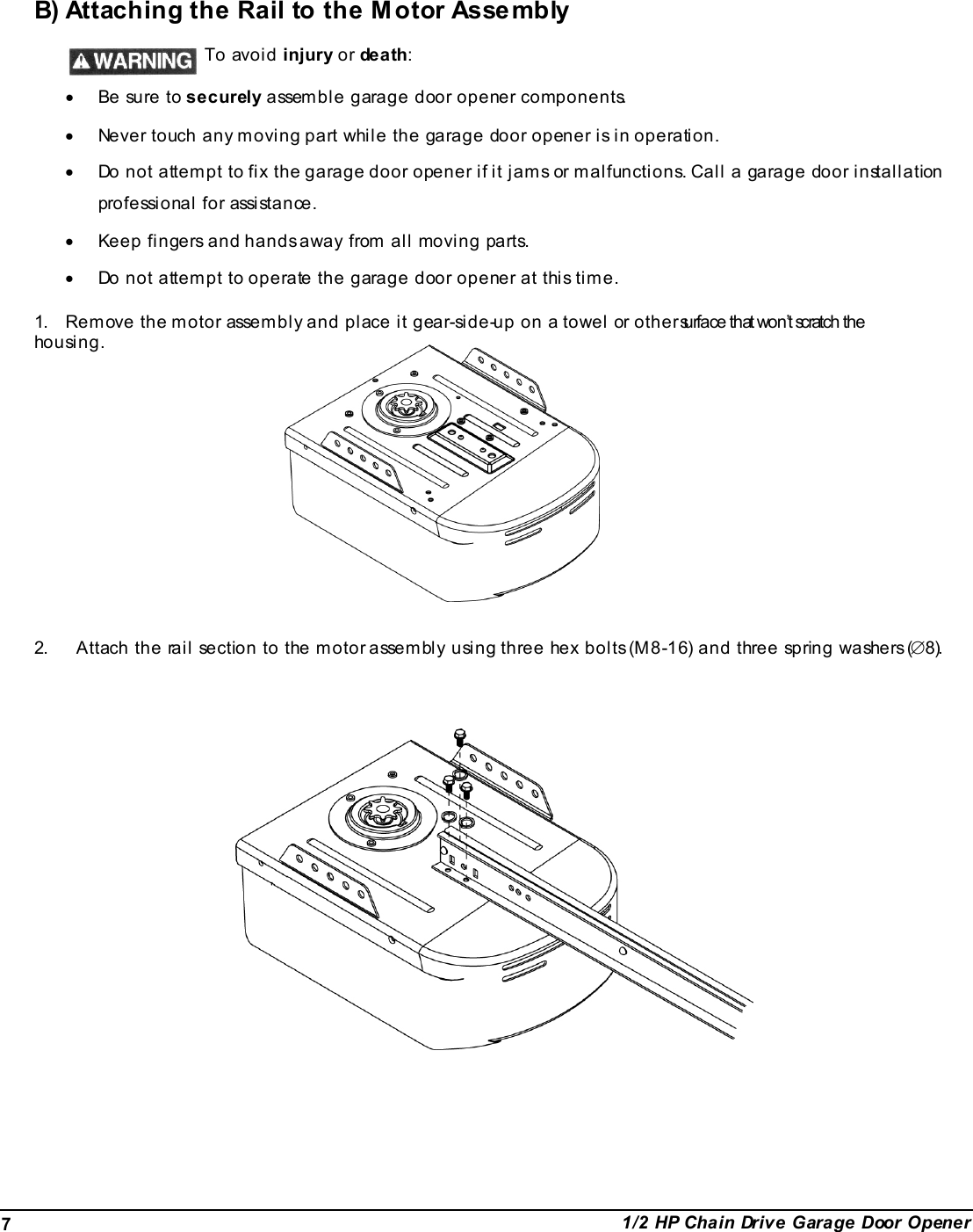
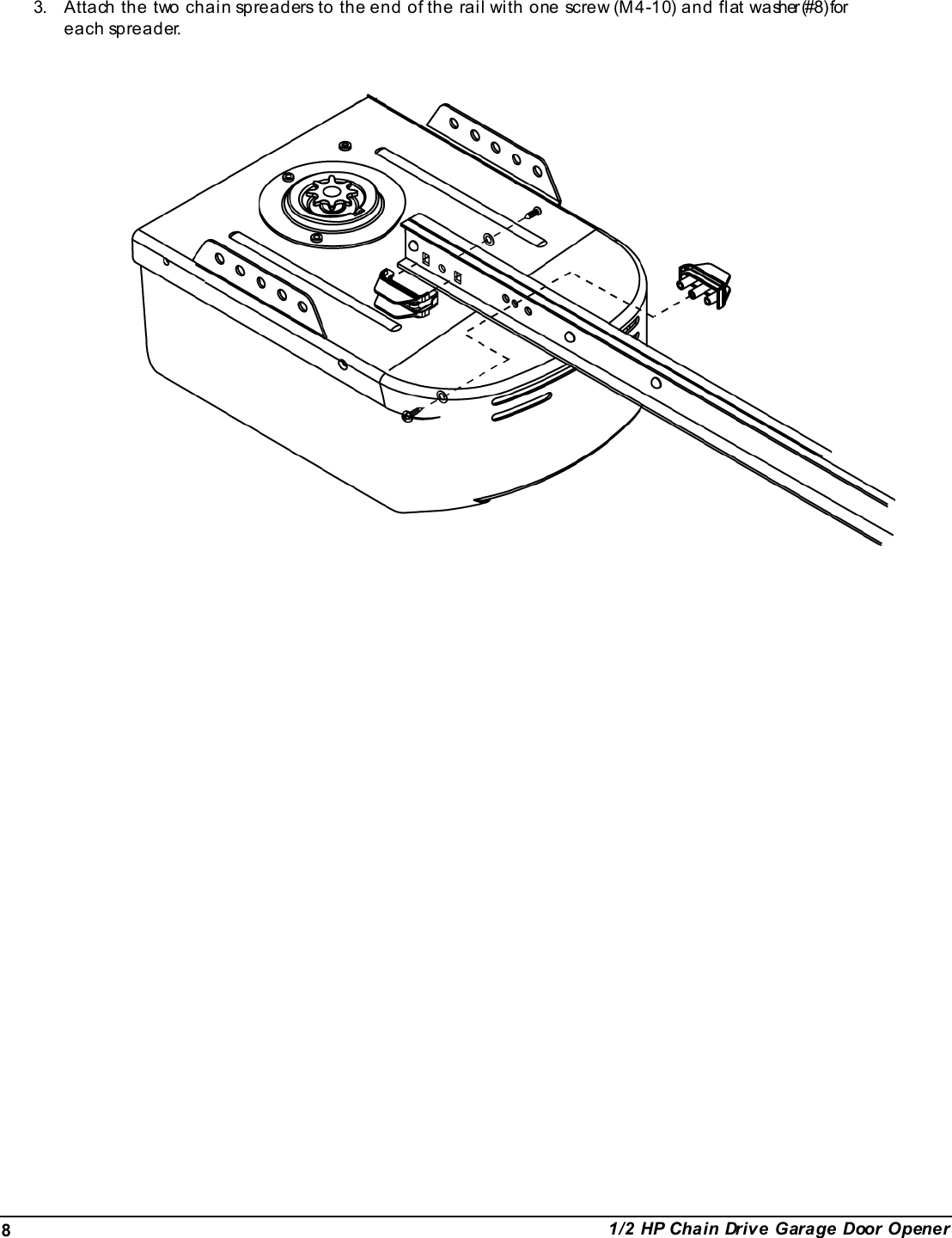
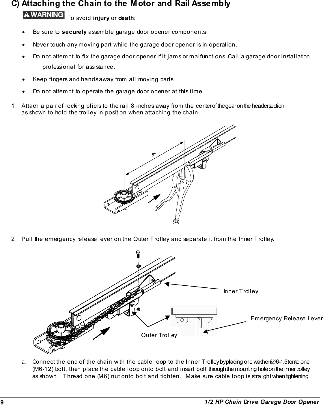
User Manual
Discussion / Help
Navigation