Rheem Professional Classic Series Direct Vent For Manufactured Housing Use And Care Manual
2015-04-02
: Rheem Rheem-Professional-Classic-Series-Direct-Vent-For-Manufactured-Housing-Use-And-Care-Manual-683504 rheem-professional-classic-series-direct-vent-for-manufactured-housing-use-and-care-manual-683504 rheem pdf
Open the PDF directly: View PDF ![]() .
.
Page Count: 28
AP14561-2 (12/09)
! FOR YOUR SAFETY!
— Do not store or use gasoline or other flammable
vapors or liquids or other combustible materials
in the vicinity of this or any other appliance. To
do so may result in an explosion or fire.
—WHAT TO DO IF YOU SMELL GAS
● Do not try to light any appliance.
● Do not touch any electrical switch; do not
use any phone in your building.
● Immediately call your gas supplier from a
neighbor’s phone. Follow the gas supplier’s
instructions.
● If you cannot reach your gas supplier,
call the fire department.
● Do not return to your home until authorized
by the gas supplier or fire department.
— Improper installation, adjustment, alteration,
service or maintenance can cause injury,
property damage or death. Refer to this
manual. Installation and service must be
performed by a qualified installer, service
agency or the gas supplier.
WARNING: If the information in these instructions is not followed exactly,
a fire or explosion may result causing property damage, personal injury or death.
!
Use & Care Manual
With Installation Instructions for the Installer
Printed in USA
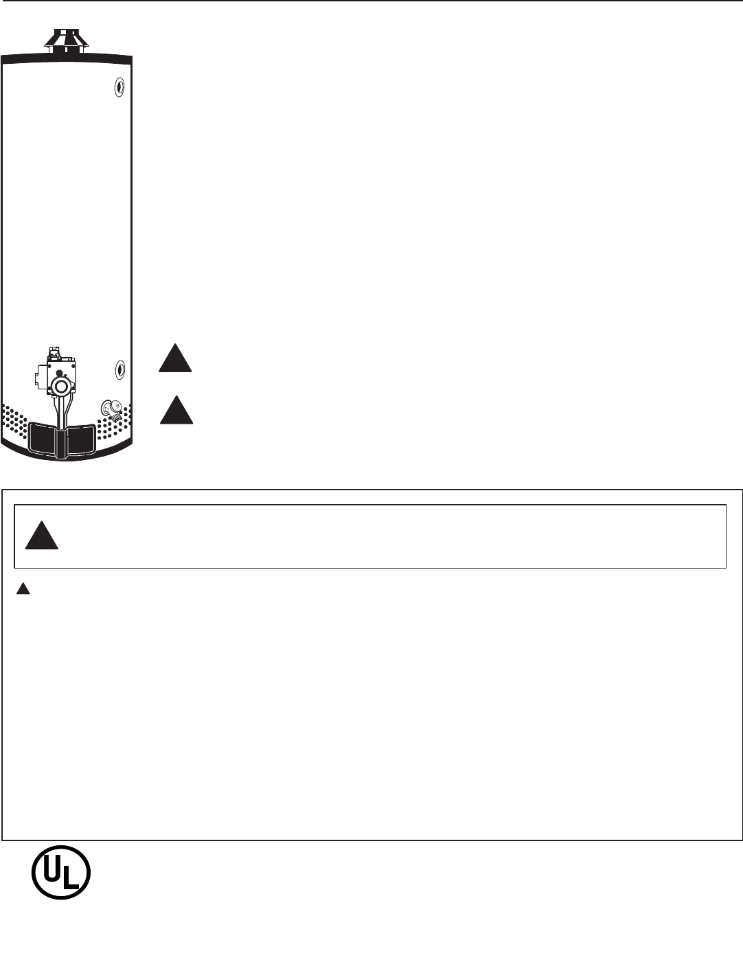
Water Heaters
Side Inlet - Direct Vent Gas
For Manufactured Housing
®
LISTED
984U
Gas-Fired Water Heater
for Mobile Homes
The purpose of this manual is twofold: one, to provide the installer with the basic directions and
recommendations for the proper installation and adjustment of the water heater; and two, for the owner–
operator, to explain the features, operation, safety precautions, maintenance and troubleshooting of the
water heater. This manual also includes a parts list.
It is very important that all persons who are expected to install, operate or adjust this water heater
read the instructions carefully so they may understand how to perform these operations. If you do not
understand these instructions or any terms within it, seek professional assistance.
Any questions regarding the operation, maintenance, service or warranty of this water heater should
be directed to the seller from whom it was purchased. If additional information is required, refer to the
section on “If you need service.”
Do not destroy this manual. Please read carefully and keep in a safe place for future reference.
Recognize this symbol as an indication of Important Safety Information!
California Proposition 65 Warning: This product contains chemicals known to the State of
California to cause cancer, birth defects or other reproductive harm.
!
!
Safety Information
Safety Precautions . . . . . . . 3–6
LP Gas Models . . . . . . . . . . . 5
Installation Instructions
Location ................. 7
Installation Methods . . . . 8-10
Water Connections . . . . . . . 11
Gas Supply . . . . . . . . . . . . . . 13
Installation Checklist . . . . . . .14
Operating Instructions
Lighting Instructions . . . . . . 15
Water Temperature . . . . 16, 17
Care and Cleaning
Draining ................ 18
Maintenance . . . . . . . . . . . . . 18
Burner Inspection . . . . . . . . 19
Extended Shut-Down . . . . . 19
Troubleshooting Tips
Before You Call
For Service . . . . . . . . . . . 20, 21
Customer Service
Parts List . . . . . . . . . . . . . . . . 22
Conversion
Instructions . . . . . . . . . . . .23-26
If You Need Service . . . . . . 28
2
FOR YOUR RECORDS
Write the model and serial numbers here:
#
#
You can find them on a label on the appliance.
Staple sales slip or cancelled check here.
Proof of the original purchase date is needed to obtain service under
the warranty.
Inside you will find many helpful hints on how to use and maintain
your water heater properly. A little preventive care on your part can
save you time and money over the life of your water heater.
You’ll find many answers to common problems in the
Troubleshooting Guide. If you review the chart of Troubleshooting
Tips first, you may not need to call for service.
READ THIS MANUAL
Your safety and the safety of others are very important. There
are many important safety messages in this manual and on your
appliance. Always read and obey all safety messages.
This is the safety alert symbol. Recognize this symbol as an
indication of Important Safety Information!
This symbol alerts you to potential hazards that can kill or hurt
you and others.
All safety messages will follow the safety alert symbol and
either the word “DANGER”, “WARNING”, “CAUTION” or
“NOTICE”.
These words mean:
!DANGER An imminently hazardous situation
that will result in death or serious
injury.
!WARNING A potentially hazardous situation that
could result in death or serious injury
and/or damage to property.
!CAUTION A potentially hazardous situation that
may result in minor or moderate
injury.
Notice: Attention is called to observe a
specified procedure or maintain
a specific condition.
READ THE SAFETY INFORMATION
!
Be sure to read and understand the entire Use and Care Manual before attempting to install or operate
this water heater. It may save you time and cost. Pay particular attention to the Safety Instructions.
Failure to follow these warnings could result in serious bodily injury or death. Should you have
problems understanding the instructions in this manual, or have any questions, STOP, and get help
from a qualified service technician, or the local gas utility.
IMPORTANT SAFETY INFORMATION.
READ ALL INSTRUCTIONS BEFORE USING.
3
Failure to install the vent system and properly vent the water heater to the outdoors as
outlined in the Venting Section of the Installation Instructions in this manual can result in
unsafe operation of the water heater. To avoid the risk of fire, explosion, or asphyxiation
from carbon monoxide, never operate this water heater unless it is properly vented and
has an adequate air supply for proper operation. Be sure to inspect the vent system
for proper installation at initial start-up; and at least annually thereafter. Refer to the
Care and Cleaning section of this manual for more information regarding vent system
inspection.
!
DANGER!
INSTALL THE VENT SYSTEM AND PROPERLY VENT THE
WATER HEATER…
Gasoline, as well as other flammable materials and liquids (which include but not limited
to adhesives, solvents, paint thinners etc.), and the vapors they produce are extremely
dangerous. DO NOT handle, use or store gasoline or other flammable or combustible
materials anywhere near or in the vicinity of a water heater or any other appliance. Be
sure to read and follow the warning label pictured below and other labels on the water
heater, as well as the warnings printed in this manual. Failure to do so can result in
property damage, bodily injury or death.
!
WARNING!
!
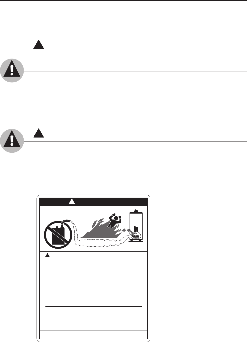
DANGER
!
FLAMMABLES
Flammable Vapors
Vapors from flammable
liquids will explode and
catch fire causing death or
severe burns
Do not use or store flammable
products such as gasoline,
solvents or adhesives in the
same room or area near the
water heater.
Keep flammable products:
1. far away from heater,
2. in approved containers,
3. tightly closed and
4. out of children's reach.
Water heater has a main
burner and pilot flame.
The pilot flame:
1. is on all the time and
2. will ignite flammable
vapors.
Vapors:
1. cannot be seen,
2. are heavier than air,
3. go a long way on the
floor and
4. can be carried from
other rooms to the pilot
flame by air currents.
Installation:
Do not install water heater
where flammable products will
be stored or used unless the
main burner and pilot flames
are at least 18" above the
floor. This will reduce, but not
eliminate, the risk of vapors
being ignited by the main
burner or pilot flame.
Read and follow water heater warnings and instructions. If owners
manual is missing, contact the retailer or manufacturer.
IMPORTANT SAFETY INFORMATION.
READ ALL INSTRUCTIONS BEFORE USING.
4
The chart shown above may be used as a guide
in determining the proper water temperature for your
home.
!
DANGER: Households with small children, disabled, or
elderly persons may require a 120°F. or lower thermostat
setting to prevent contact with “HOT” water.
Maximum water temperatures occur just after
burner has shut off. To find water temperature being
delivered, turn on a hot water faucet and place
a thermometer in the water stream and read the
thermometer.
The temperature of the water in the heater can
be regulated by setting the temperature dial on the
front of the gas control (thermostat). To comply with
safety regulations the thermostat was set at its lowest
setting before the water heater was shipped from the
factory.
The illustration at
the left details the
approximate water
temperature
for each mark on
the Gas Control
(Thermostat)
Temperature Dial.
DANGER: Hotter water increases the potential for
Hot Water SCALDS.
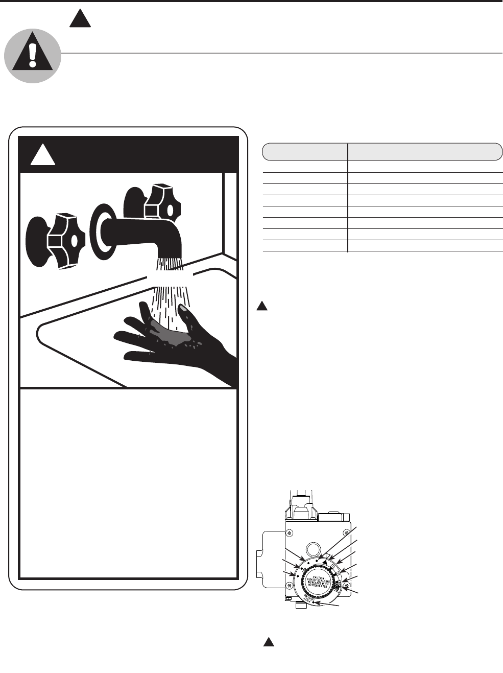
DANGER
!
HOT
Water temperature over 125°F can
cause severe burns instantly or
death from scalds.
Children, disabled and elderly are
at highest risk of being scalded.
See instruction manual before
setting temperature at water
heater.
Feel water before bathing or
showering.
Temperature limiting valves are
available, see manual.
BURN
!
DANGER!
WATER TEMPERATURE SETTING
Safety and energy conservation are factors to be considered when selecting the water
temperature setting of water heater’s thermostat. Water temperatures above 125°F.
can cause severe burns or death from scalding. Be sure to read and follow the warnings
outlined on the label pictured below. This label is also located on the water heater.
Notice: Mixing valves are available for reducing point
of use water temperature by mixing hot and cold water
in branch water lines . Contact a licensed plumber or the
local plumbing authority for further information.
Time/Temperature Relationship in Scalds
Water Temperature Time To Produce a Serious Burn
120°F More than 5 minutes
125°F 11/2 to 2 minutes
130°F About 30 seconds
135°F About 10 seconds
140°F Less than 5 seconds
145°F Less than 3 seconds
150°F About 11/2 seconds
155°F About 1 second
Table courtesy of Shriners Burn Institute
!
155°F
150°F
140°F
110°F
80°F
Temperatures are approximate
90°F
100°F 130°F
120°F
45°F
5
LP and natural gas have an odorant added to aid in detecting a gas leak. Some
people may not physically be able to smell or recognize this odorant. If you are unsure or
unfamiliar with the smell of LP or natural gas, ask the gas supplier. Other conditions, such
as “odorant fade”, which causes the odorant to diminish in intensity, can also hide or
camouflage a gas leak.
!
DANGER!
LIQUEFIED PETROLEUM (LP - PROPANE OR BUTANE)
AND NATURAL GAS MODELS
● This water heater is supplied with a
thermostatic gas valve that is convertible
to LP from natural gas. Be sure to read
and carefully follow the Conversion
Instructions included in this manual
when converting the valve from one
type of gas to another.
● After conversion, be certain that the gas
supplied to the heater is the type that
the valve has been converted for (LP for
heaters converted to LP use, and natural
gas for heaters converted to natural gas
use). This water heater will not operate
safely if connected to a fuel type other
than the one the gas valve is converted
for.
● LP gas must be used with great caution.
It is heavier than air and will collect first
in lower areas making it hard to detect at
nose level.
● Before attempting to light the water
heater, make sure to look and smell for
gas leaks. Use a soapy solution to check
all gas fittings and connections. Bubbling
at a connection indicates a leak that must
be corrected. When smelling to detect an
LP leak, be sure to sniff near the floor
also.
● Gas detectors are recommended in LP
and natural gas applications and their
installation should be in accordance with
the manufacturer’s recommendations
and/or local laws, rules, regulations or
customs.
● It is recommended that more than one
method, such as soapy solution, gas
detectors, be used to detect leaks in LP
gas applications.
!
DANGER: If a gas leak is present or
suspected:
● Do not attempt to find the cause
yourself.
● Do not try to light any appliance.
● Do not touch any electrical switch.
● Do not use any phone in your building.
● Leave the house immediately and make
sure your family and pets leave also.
● Leave the doors open for ventilation
and contact the gas supplier, a qualified
service agency or the fire department.
● Stay away from the house (or building)
until the service call has been made, the
leak is corrected and a qualified agency
has determined the area to be safe.
6
● Read this manual entirely before installing
or operating the water heater.
● Use this appliance only for its intended
purpose as described in this Use and Care
Manual.
● Be sure your appliance is properly installed
by a qualified technician in accordance
with the provided installation instructions.
● Do not attempt to repair or replace any part
of your water heater unless it is specifically
recommended in this manual. All other
servicing should be referred to a qualified
technician.
Have the installer show you the location of the gas shut-off valve and how to shut it off
if necessary. Turn off the manual shut-off valve if the water heater has been subjected to
overheating, fire, flood, physical damage or if the gas supply fails to shut off.
SAFETY PRECAUTIONS
IMPORTANT SAFETY INFORMATION.
READ ALL INSTRUCTIONS BEFORE USING.
!
WARNING!
For your safety, the information in this manual must be followed to minimize the risk of
fire or explosion, electric shock, or to prevent property damage, personal injury, or loss of
life.
FOR INSTALLATIONS IN THE STATE OF CALIFORNIA
California Law requires that residential water heaters must be braced, anchored or
strapped to resist falling or horizontal displacement due to earthquake motions. For
residential water heaters up to 52 gallon capacity, a brochure with generic earthquake
bracing instructions can be obtained from: Office of the State Architect, 400 P Street,
Sacramento, CA 95814 or you may call 916-324-5315 or ask a water heater dealer.
However, applicable local codes shall govern installation. For residential water heaters
of a capacity greater than 52 gallons, consult the local building jurisdiction for acceptable
bracing procedures.
READ AND FOLLOW THIS SAFETY INFORMATION CAREFULLY.
SAVE THESE INSTRUCTIONS
Installing the water heater.
The installation of this water heater must be in accordance with the Manufactured Home Construction
and Safety Standard (Title 24, CFR; Part 3280) and the following instructions; supplied with the roof
jack assembly, local codes, and utility company requirements governing the installation of water heaters
in manufactured homes (mobile homes) and/or in the absence of local codes, the latest edition of The
National Fuel Gas Code, ANSI Z223.1.
Location
This water heater must be installed within
an enclosure so as to separate the water
heater’s combustion and venting system
from the interior atmosphere of the
manufactured home.
All air for combustion must be obtained
from the outside atmosphere, and the
products of combustion (flue gases) must
be discharged directly to the outside
atmosphere through the gas vent roof jack
assembly.
Refer to installation illustration as shown
on the next page of this manual.
The water heater should not be located in
an area where leakage from the tank or
connections will result in damage to the
area adjacent to the heater.
When such areas cannot be avoided it is
recommended that a suitable catch pan,
adequately drained, must be installed
under the water heater.
Catch pan kits are available from the store
where the water heater was purchased, or
any water heater distributor. Follow the
instructions provided with the catch pan
kit for proper installation.
Make certain that the floor underneath the
water heater is strong enough to support
the weight of the water heater once it is
filled with water.
A gas fired water heater or any other
appliance should not be installed
in a space where liquids which give off
flammable vapors are to be used or stored.
Such liquids include gasoline, LP gas
(butane or propane), paint or adhesives
and their thinners, solvents or removers.
● Long hot water lines should be insulated
to conserve water and energy.
● The water heater and water lines should
be protected from exposure to freezing
temperatures.
● Minimum clearance from combustible
construction:
If the clearances stated on the Instruction/
Warning Label, located on the front of
the heater differ, install the water heater
according to the clearances stated on the
label.
The water heater may be installed on
combustible flooring, but not directly on
carpeting.
If the water heater must be installed on
carpeting, place a wood or metal panel
beneath the water heater extending beyond
its full width and depth at least 3” in all
directions. If the water heater is installed
in an alcove or closet, the entire floor
must be covered by the panel.
CAUTION: Provisions should be made
so that in the event the water heater or one
of its fittings were to leak, the resulting
flow of water will not cause damage to the
manufactured home.
CAUTION: DO NOT subject the
water heater to any water distribution
system air pressure test. The water
heater should either be isolated with
valves at the inlet and outlet water
connections or disconnected during the
test. Failure to properly isolate the
water heater during an air pressure test
presents a hazard to life and property.
With a water pressure test the water
heater need not be isolated.
7
!WARNING: Combustible
construction refers to
adjacent walls and ceilings
and should not be confused
with combustible or
flammable products and
materials. Combustible and/
or flammable products and
materials should never be
stored in the vicinity of this
or any gas appliance.
Location Front of
Control Sides Rear Ceiling
Closet 4” 0” 0” 24”
8
Installing the water heater.
Installation Methods
Inspect shipment.
—
Inspect the water
heater for possible shipping damage.
Placement of water heater.
—
Locate
the water heater as desired, make
certain the minimum clearances
outlined in this manual are observed.
Combustion and ventilation air.
—
Air
for combustion and ventilation must
not be supplied from occupied spaces
of the mobile home. The air inlet
must not be obstructed under any
circumstances. Outside air is
necessary for proper and safe
operation of the water heater.
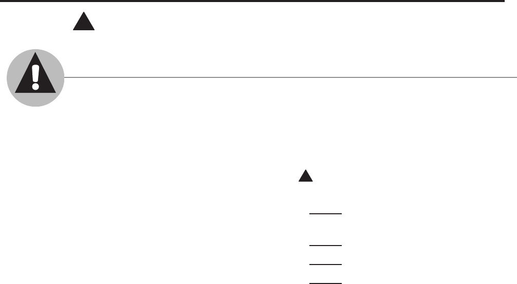
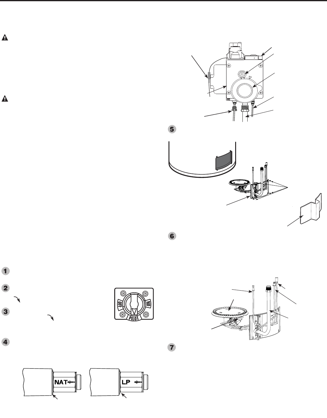
Openings for air inlet and gas vent roof
jack assemblies.
—
(Refer to
illustrations to the left.) Cut a 7
1
/
4
in.
diameter hole in the ceiling and roof
directly above the flue of the water
heater. Remove the water heater and
drop a plumb line from the center of the
hole in the roof to the floor. Mark this
water heater center point on the floor.
Mark a "new point" on the floor 4
3
/
4
in.
toward the front from the water heater
center point for a 30 gallon model, or
5
3
/
4
in. toward the front from the water
heater center point for a 40 gallon
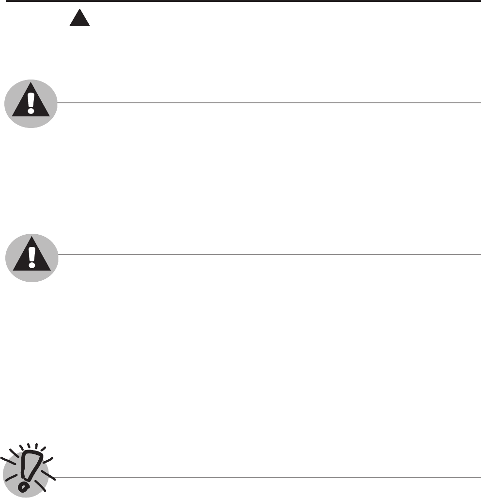
model. For a 50 gallon model, mark a
"new point" 4
3
/
4
in. to the right and 4
3
/
4
in. toward the front from the water
heater center point. Cut a 4
3
/
4
in.
diameter hole in the floor and underside
sheathing using the "new point" as the
hole center.
AIR INLET ASSEMBLY — (Refer to
illustrations to the left.)
NOTICE — Installation of this Direct
Vent water heater with the Air Inlet
Assembly taking it’s combustion
air from a basement atmosphere is
a violation of UL 307b, Section 4.3
(c). For installation over a basement
structure or unvented crawl space,
provisions must be made to provide
fresh combustion air from outside the
dwelling. A factory manufactured Side
Air Inlet Kit (Part No. AP12191) may be
purchased from the factory and installed
according to the instructions supplied
with the kit.
To accommodate variations of
installation configurations, an
adjustable Air Inlet Assembly is
available (Purchased separately). To
adjust it, measure the distance from the
4
3
/
4
in. diameter hole in the floor (refer
to number 4) and the approximate mid-
point of the space between the bottom
sheathing and the ground, and record
the dimension. Adjust the telescopic
lower tube of the inlet assembly until
the distance between the bottom of the
floor flange to the bottom of the
telescopic tube is equal to the
dimension below the floor recorded
earlier. With the tube adjusted to the
correct length, secure the lower
telescopic tube in place with the screws
provided. A silicone rubber sealing
band is provided with the inlet
assembly, and must be pulled up over
the joint between the tubes to ensure
leak proof seal.
Now drop the Air Inlet Assembly into
the 4
3
/
4
in. diameter hole in the floor
and fasten in place at this time with the
screws provided.
Relocate the water heater so the air
inlet collar, that extends below the
water heater bottom pan, aligns with
the Air Inlet Assembly tube projecting
through the floor. Close off the opening
between the top of the Air Inlet
Assembly tube and the water heater air
inlet collar with the clamp provided
Align the water heater flue with the
opening previously cut in the ceiling
and roof. The opening around the Air
Inlet Assembly and the bottom sheathing
must be sealed to prevent the entrance of
rodents. When the mobile home is tightly
skirted, an air inlet opening in the skirt
must be provided. The opening must have
a minimum free area of at least 9 square
inches. If the opening is screened or
covered with a louver, the total free area
must be at least 9 square inches.
Center Line of 7¼"
Diameter Hole in Roof
and Ceiling
Center Point
of Heater
4¾" for 30 Gallon Heater
5¾" for 40 Gallon Heater
4¾" Diameter Holes
Through Floor and
Sheathing
FRONT OF HEATER
For 30 & 40 Gallon Heaters ONLY!!
Center Point
of Heater
4¾" Diameter Holes
Through Floor and
Sheathing
FRONT OF HEATER
For 50 Gallon Heater ONLY!!
4¾" to the right of the center line
of heater and
4¾" towards front of heater
Roof Jack Sizing Table
* Adjustable Length Roof Jacks
▲ Fixed Length Roof Jacks
Roof Jack Kits contain specied Roof Jack AND Air
Inlet Assembly.
§ These Part No.’s are for Roof Jack ONLY.
NOTICE: 24” Minimum distance from the top of the water
heater to the ceiling.
NOTICE - A Roof Jack Extension Kit (Part Number
AP12021) is recommended for roof pitches of 5½ -12 or
greater, or for installations where local codes require the
Roof Jack to be installed above the peak of the roof. Instal-
lation instructions are provided with the kit.
Access Door (Right or Left)
No Openings Required
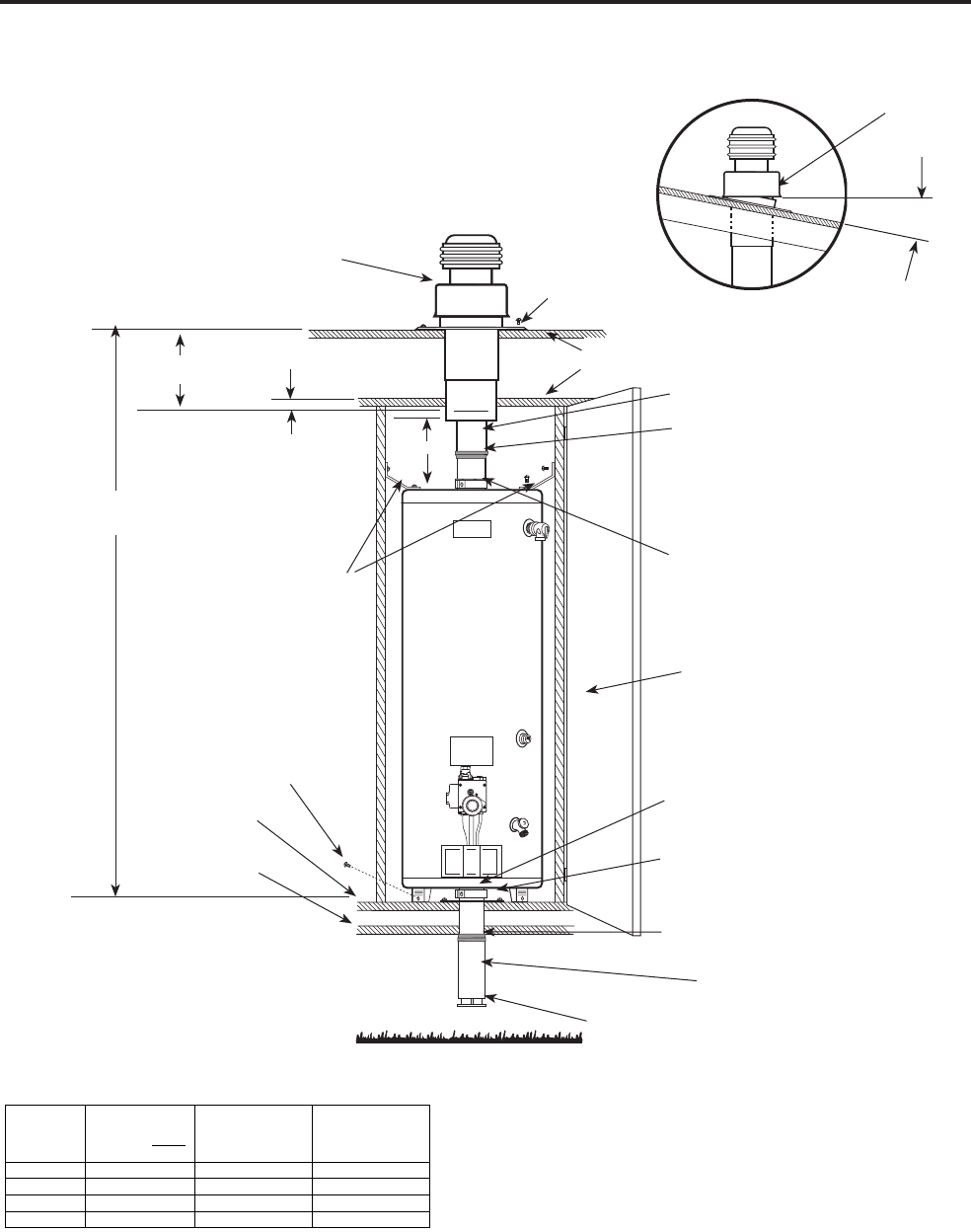
Roof Jack
(Purchased Separately) Roof Flange
Roof
Ceiling
Floor
Bottom
Sheathing
Clamp (AE28924)
Supplied with Heater
Clamp (AE28924) and Gasket
(AP12014)
Supplied with Heater
Telescopic Vent Connector Pipe
(Supplied with Roof Jack)
Silicone Rubber Seal
(Supplied with Roof Jack)
Silicone Rubber Seal
(Supplied with Air Inlet Assembly )
Ground Level
Secure Strapping (AP11154)
to Water Heater Top Pan and
Enclosure Sides with S.M.
Screws provided
S.M. Screw (2 Supplied)
to Secure Legs to Floor
S.M. Screws to Secure Flashing to
Floor
NOTICE: Opening of Air Inlet Assembly must
be below bottom sheathing and unobstructed to
provide adequate combustion air supply to heater.
Air Inlet Assembly
2" ª
6" Min.
"X" Dimension
(See Table Below)
Roof Jack
Adjustment Range
Legend
• 6" Minimum distance between bottom edge
of the roof jack outer pipe and the top of the
water heater.
ª 2” is minimum distance between ceiling and
"Must be installed below ceiling" line on Roof
Jack.
Roof Jack Kit
Part No.
Roof Jack ONLY
Part No. §
"X" Dimension (See
Illustration)
Roof Jack Adjustment
Range (See
Illustration)
AP12032B* AP12118B* 98" Min./126" Max. 16" Min./ 32" Max.
AP12032C* AP12118C* 112" Min./154" Max. 30" Min./60" Max.
AP12032D* AP12118D* 130" Min./ 189" Max. 48" Min./95" Max.
AP12032E▲AP12119B* 94" Min./ 106" Max. 12"
This appliance must be installed in accordance with the
Manufactured Home Construction and Safety Standard (Title
24, CFR; Part 3280), the following instructions, local codes
and utility company requirements governing the installation
of water heaters in manufactured homes (mobile homes),
and/or in the absence of local codes, the latest edition of The
National Fuel Gas Code, ANSI Z223.1.
This water heater complies with Section 3280.707(d) (2) of
H.U.D. Mobile Home Construction and Safety Standards.
NOTICE - All sizes of Roof Jacks have an adjustable tilt Roof
Flange to accommodate installation on a pitched roof. Maximum
roof pitch is 5½ - 12. For roof pitches greater than 5½ - 12, the use
of a ”wedge” under the roof ange is acceptable provided it is sealed
and secured.
25° Max.
(5
1
/
2
-12 Pitch)
Adjustable Tilt
Roof Flange
9

10
Installing the water heater.
Gas vent roof jack.
—
The roof jack is
not supplied with the water heater as
a component part. The roof jack must
be one of the models listed in this
manual, and marked as approved by
Underwriters Laboratories, Inc. for
use on manufactured homes (mobile
homes). The installation instructions
supplied with each roof jack must be
observed to obtain the proper roof
jack installation.
(See Illustration on page 9) The Gas
Vent Roof Jack Assembly (purchased
separately) has a multi piece telescopic
vent connector pipe consisting of an
upper, center and lower section that
must be pre-adjusted according to
the following directions prior to final
installation of the roof jack.
From the water heater location, measure
the distance from the highest point on
roof opening to the floor. Select correct
size Roof Jack and Air Inlet Assembly
from Roof Jack Sizing Guide on Page
9, Dimension X. Remove the Roof Jack
from its carton, and extend the center
section of the inner most pipe to its
maximum length by grasping the pipe
and sliding the center section of pipe
downward. Then extend the lower section
of the inner pipe in the same manner to
its full extension. Silicone rubber sealing
bands are provided and must be pulled
down over the joints between the tubes to
ensure a leak proof seal.
Apply a non-hardening mastic on the
roof around the previously cut hole to
form a weather tight seal with the roof
flange of the Roof Jack Assembly. Insert
the roof jack through the opening in roof
from above, and fasten the flashing to
the roof using the pre-punched holes in
the flashing. (The roof flange adjusts to
accommodate installation on a pitched
roof, maximum allowable pitch is
5
1
/
2
-12. For roof pitches greater that
5
1
/
2
-12, the use of a ”wedge” under the
roof flange is acceptable provided it is
sealed and secured.) Apply additional
non-hardening mastic as required to
complete the weather seal.
With Roof Jack in place and secured to
the roof, insure that the line on the larger,
outer tube of the Roof Jack, which is
marked “INSTALL WITH THIS LINE
BELOW CEILING” is located no less
than 2” below the ceiling line and no less
than six inches above the water heater.
Refer to page 9.
Now extend the lower section of the
vent connector pipe by grasping the
center section of pipe, ensuring that the
silicone rubber seal remains in position
over the joint, and sliding the lower
section of pipe downward, over the flue
pipe protruding above the water heater’s
top pan. Be sure to leave approximately
1/16” to 1/8” of flue pipe exposed below
the lower section of the vent connector
pipe to ensure a good sealing surface for
the gasket. To complete the Roof Jack
Assembly installation, position the gasket
material (white fiberglass like material
with self adhesive tab, supplied in plastic
bag on heater) and clamp (supplied in
carton with water heater) around the
intersection of the flue pipe and the lower
section of the vent connector pipe, and
tighten the clamp as required to provide a
good seal at the joint.
Securing the water heater.
—
Secure
the two front legs of the water heater to
the floor using the 2 long screws
furnished. Attach the bracket (AP11154)
to the top pan of the water heater and
fasten the bracket to the adjacent
walls on each side.
11
Thermal Expansion
Determine if a check valve exists in the inlet water
line. Check with your local water utility company.
It may have been installed in the cold water line
as a separate back flow preventer, or it may be
part of a pressure reducing valve, water meter or
water softener. A check valve located in the cold
water inlet line can cause what is referred to as a
“closed water system”. A cold water inlet line with
no check valve or back flow prevention device is
referred to as an “open” water system.
As water is heated, it expands in volume and
creates an increase in the pressure within the water
system. This action is referred to as “thermal
expansion”. In an “open” water system, expanding
water which exceeds the capacity of the water
heater flows back into the city main where the
pressure is easily dissipated.
A “closed water system”, however, prevents the
expanding water from flowing back into the main
supply line, and the result of “thermal expansion”
can create a rapid and dangerous pressure increase
in the water heater and system piping. This rapid
pressure increase can quickly reach the safety
setting of the relief valve, causing it to operate
during each heating cycle. Thermal expansion,
and the resulting rapid, and repeated expansion
and contraction of components in the water heater
and piping system can cause premature failure
of the relief valve, and possibly the heater itself.
Replacing the relief valve will not correct the
problem!
The suggested method of controlling thermal
expansion is to install an expansion tank in the
cold water line between the water heater and
the check valve. The expansion tank is designed
with an air cushion built in that compresses as
the system pressure increases, thereby relieving
the over pressure condition and eliminating the
repeated operation of the relief valve. Other
methods of controlling thermal expansion are also
available. Contact your installing contractor, water
supplier or plumbing inspector for additional
information regarding this subject.
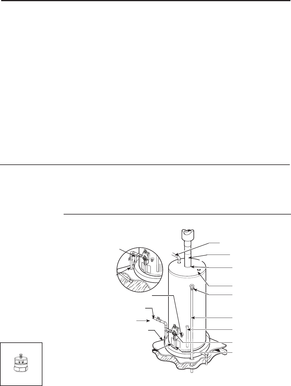
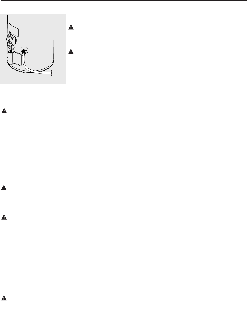
Water Supply Connections
Refer to the illustration below for suggested
typical installation. The installation of unions or
flexible copper connectors is recommended on the
hot and cold water connections so that the water
heater may be easily disconnected for servicing if
necessary. The HOT and COLD water connections
are clearly marked and are 3/4” NPT on all
models. Install a shut-off valve in the cold water
line near the water heater.
IMPORTANT: Do
not apply heat to the
HOT or COLD water
connections. If sweat
connections are used,
sweat tubing to adapter
before fitting adapter
to the cold water
connections on heater.
Any heat applied to
the cold water supply
fittings will permanently
damage the dip tube.
Alternate sediment
trap location
To gas supply
To gas supply
To cold water supply
Relief valve discharge line
to suitable drain
Sediment trap
Drain valve
Manual gas shut-off
Sediment trap
Ground joint union or ANSI design
certified semi-rigid or flexible gas
appliance connector
Thermostat
Jacket door
Anode
Temperature and
pressure relief valve
Flue baffle
(underneath)
Roof jack
Hot water outlet to fixtures
Typical Installation
NOTICE: The National
Fuel Gas Code (NFGC)
mandates a manual gas
shut-off valve: See (NFGC)
for complete instructions.
Local codes or plumbing
authority requirements may
vary from the instructions
or diagrams provided and
take precedent over these
instructions.
Vacuum Relief Valve
(Not Supplied)
If required, install per local codes
and valve manufacturer’s
instructions.

12
Installing the water heater.
Condensation
Condensation can form on the tank when it
is first filled with water. Condensation might
also occur with a heavy water draw and very
cold inlet water temperatures.
Drops of water falling on the burner can
produce a sizzling or pinging sound, and the
water may also be seen beneath the water
heater.
This condition is not unusual, and will
disappear after the water becomes heated. If,
however, the condensation continues, examine
the piping and fittings for possible leaks.
Additional information on this subject may
be found at www.rheem.com, under Rheem
Water Heating, "Support", scroll down to
the Technical Service Bulletins 1400 Series
Section and choose Bulletin #1402.
!
WARNING: The tank
must be full of water
before heater is turned
on. The water heater
warranty does not cover
damage or failure
resulting from operation
with an empty or
partially empty tank.
To Fill the Water Heater
Make certain that drain valve is closed, then
open the shut-off valve in the cold water
supply line.
Open each hot water faucet slowly to allow
the air to vent from the water heater and
piping.
A steady flow of water from the hot water
faucet(s) indicates a full water heater.
A new combination temperature and pressure relief valve, complying with the Standard for Relief Valves
and Automatic Gas Shut-Off Devices for Hot Water Supply Systems, ANSI Z21.22, is supplied and must
remain in the opening provided and marked for the purpose on the water heater. No valve of any type
should be installed between the relief valve and the tank. Local codes shall govern the installation of
relief valves.
Relief Valve
The pressure rating of the relief valve must
not exceed 150 PSI, the maximum working
pressure of the water heater as marked on the
rating plate.
The BTUH rating of the relief valve must
equal or exceed the BTUH input of the water
heater as marked on its rating plate.
Position the outlet of the relief valve above
a suitable open drain to eliminate potential
water damage. Piping used should be of a
type approved for hot water distribution.
The discharge line must be no smaller
than the outlet of the valve and must pitch
downward from the valve to allow complete
drainage (by gravity) of the relief valve and
discharge line.
The end of the discharge line should not
be threaded or concealed and should be
protected from freezing. No valve of any
type, restriction or reducer coupling should
be installed in the discharge line.
13
!
WARNING: Never
use an open flame to
test for gas leaks, as
bodily injury, property
damage or death could
result.
Leak Testing
The water heater and its gas connections must
be leak tested at normal operating pressures
before it is placed in operation.
Turn on the manual gas shut-off valve
near the water heater.
Use a soapy water solution to test for
leaks at all connections and fittings.
Bubbles indicate a gas leak that must be
corrected.
The factory connections to the thermostat
should also be leak tested after the water
heater is placed in operation.
Pressure Testing the Gas Supply System
The water heater and its manual gas shut-
off valve must be disconnected from the
gas supply piping system during any high
pressure testing of that system at pressures in
excess of 1/2 psi (14″ w.c.).
The water heater must be isolated from the
gas piping system by closing the manual gas
shut-off valve during any pressure testing of
the gas supply piping at pressures equal to or
less than 1/2 psi (14″ w.c.).
Gas Supply
Check the markings on the water heater’s
rating plate to be certain the type of gas
being furnished corresponds to that for which
the water heater is built. The water heater
can be converted from natural gas to LP or
vice versa. See the Conversion Instructions
section of this manual.
The branch gas supply line to the water
heater should be clean 1/2″ black steel pipe
or other approved gas piping material.
A ground joint union or ANSI design
certified semi-rigid or flexible gas appliance
connector should be installed in the gas
line close to the water heater. The HUD
code should be followed for installation and
location of a manual shutoff valve.
Compound used on the threaded joints of the
gas piping must be of the type resistant to the
action of LP gas. Use compound sparingly on
male threads only.
Where a sediment trap is not incorporated as
part of the appliance, a sediment trap shall
be installed downstream of the equipment
shutoff valve as close to the inlet of the
appliance as practical at the time of the
appliance installation. The sediment trap shall
be either a tee fitting with a capped nipple in
the bottom outlet or other device recognized
as an effective sediment trap.
Do not use excessive force (over 31.5 ft lbs.)
in tightening the pipe joint at the thermostat
inlet, particularly if teflon pipe compound is
used, as the valve body may be damaged.
The inlet gas pressure to the water heater
must not exceed 14″ w.c. for natural or LP
gas. For purposes of input adjustment, the
minimum inlet gas pressure (with main
burner on) is shown on the water heater
rating plate. If high or low gas pressures
are present, contact your gas supplier
for correction.

14
Installation Checklist
A. Water Heater Location
B. Water Supply
C. Gas Supply
❑ Water heater securely anchored.
❑ Indoors and protected from freezing
temperatures.
❑ Proper clearance from combustible surfaces
observed and water heater not installed on
carpeted floor.
❑ Sufficient fresh air supply for proper
operation of water heater.
❑ Air supply free of corrosive elements and
flammable vapors.
❑ Provisions made to protect area from water
damage.
❑ Sufficient room to service heater.
❑ Combustible materials, such as clothing,
cleaning materials, rags, etc. clear of the base
of the heater.
❑ Water heater completely filled with water.
❑ Air purged from water heater and piping.
❑ Water connections tight and free of leaks.
❑ Gas line equipped with shut-off valve, union
and sediment trap.
❑ Approved pipe joint compound used.
❑ Soap and water solution used to check all
connections and fittings for possible gas leak.
❑ Gas Company inspected installation (if
required).
❑
After conversion, be certain the gas
supplied to the heater is the type the
valve has been converted for (LP for
heaters converted to LP use, and natural
gas for heaters converted to natural gas
use)
.
D. Relief Valve
❑ Temperature and Pressure Relief Valve
properly installed and discharge line run
beneath mobile home.
❑ Discharge line protected from freezing.
E. Venting
❑ Flue baffle properly hung in top of heater’s
flue.
❑ Gas Vent Roof Jack properly installed.
Lighting the water heater.
Before operating this water heater, be sure to read and follow the instructions on the label pictured
below and all other labels on the water heater, as well as the warnings printed in this manual. Failure to
do so can result in unsafe operation of the water heater resulting in property damage, bodily injury, or
death. Should you have any problems reading or following the instructions in this manual, STOP, and
get help from a qualified person.
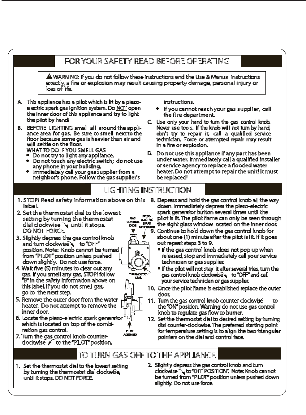
FOR YOUR SAFETY READ BEFORE OPERATING
This appliance has a pilot which is lit by a piezo-
electric spark gas ignition system. Do NOT open
the inner door of this appliance and try to light
the pilot by hand!
If you cannot reach your gas supplier, call
the fire department.
Use only your hand to turn the gas control knob.
Never use tools. If the knob will not turn by hand,
don't try to repair it, call a qualified service
technician. Force or attempted repair may result
in
Do not use this appliance if any part has been
under water. Immediately call a qualied installer
or service agency to replace a ooded water
heater. Do not attempt to repair the unit! It must
be replaced!
LIGHTING INSTRUCTION
TO TURN GAS OFF TO THE APPLIANCE
A.
a re or explosion.
C.
D.
10.
11.
instructions.
B.
Do not try to light any appliance.
Do not touch any electric switch; do not use
any phone in your building.
Immediately call your gas supplier from a
neighbor's phone. Follow the gas supplier's
BEFORE LIGHTING smell all around the appli-
ance area for gas. Be sure to smell next to the
oor because some gas is heavier than air and
will settle on the oor.
WHAT TO DO IF YOU SMELL GAS
Depress and hold the gas control knob all the way
down. Immediately depress the piezo-electric
spark generator button several times until the
pilot is lit. The pilot ame can only be seen through
the sight glass window located on the inner door.
Continue to hold down the gas control knob for
about one (1) minute after the pilot is lit. If it goes
out repeat steps 3 to 9.
If the gas control knob does not pop up when
released, stop and immediately call your service
technician or gas supplier.
If the pilot will not stay lit after several tries, turn the
gas control knob clockwise to “OFF” and call
your service technician or gas supplier.
Once the pilot ame is established replace the outer
door.
Turn the gas control knob counter-clockwise to
the “ON” position. Warning do not use gas control
knob to regulate gas ow to burner.
12.
Set the thermostat dial to desired setting by turning
dial counter-clockwise. The preferred starting point
for temperature setting is to align the two triangular
pointers on the dial and control face.
WARNING: If you do not follow these instructions and the Use & Manual instructions
exactly, a re or explosion may result causing property damage, personal injury or
loss of life.
1. 2.
Set the thermostat dial to the lowest setting
by turning the thermostat dial clockwise
until it stops. DO NOT FORCE.
Slightly depress the gas control knob and turn
clockwise to “OFF POSITION”. Note: Knob cannot
be turned from ”PILOT” position unless pushed down
slightly. Do not use force.
5.
7.
Remove the outer door from the water
heater. Do not attempt to remove the
inner door.
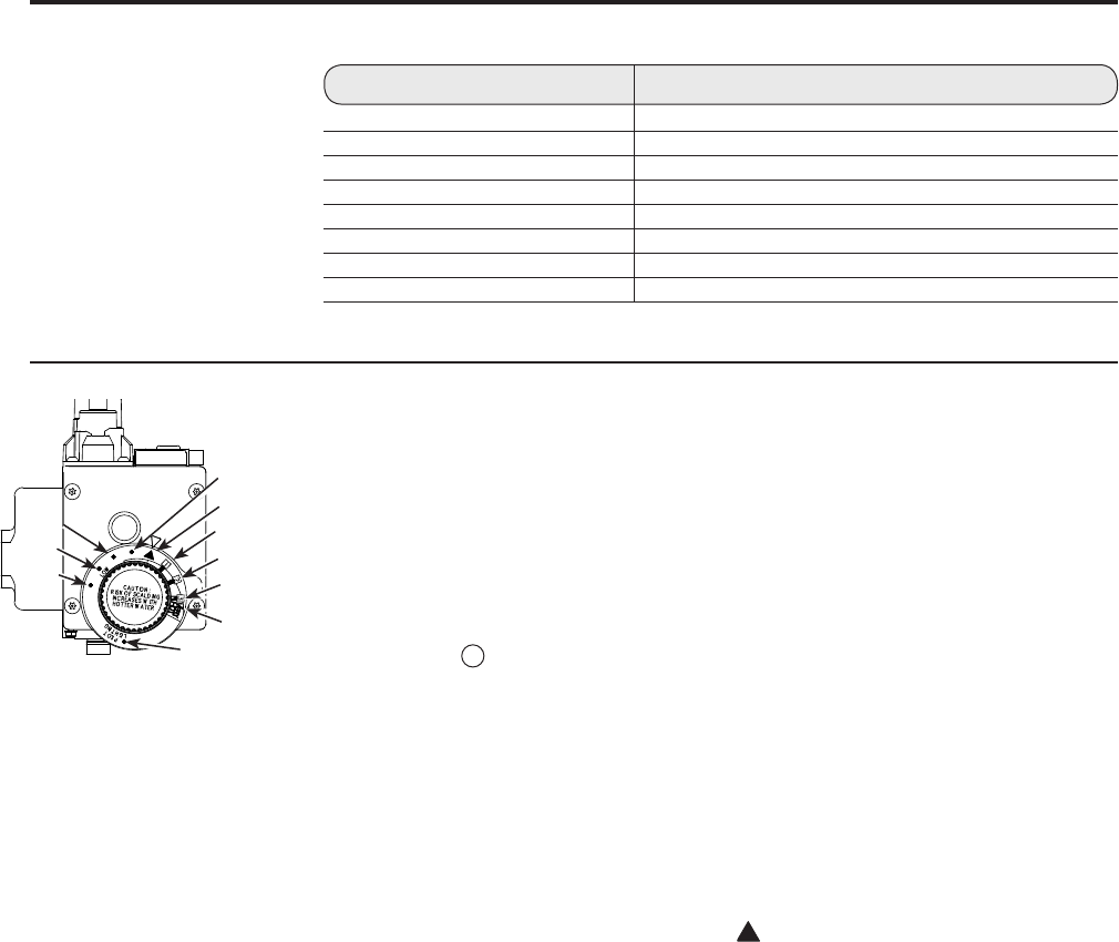
6. Locate the piezo-electric spark generator
which is located on top of the combi-
nation gas control.
PILOT
ASSEMBLY
Turn the gas control knob counter-
clockwise to the “PILOT” position.
9.
8.
STOP! Read safety information above on this
label.
Set the thermostat dial to the lowest
setting by turning the thermostat
dial clockwise until it stops.
DO NOT FORCE.
Slightly depress the gas control knob
and turn clockwise to “OFF”
position. Note: Knob cannot be turned
from “PILOT” position unless pushed
down slightly. Do not use force.
1.
4.
3.
2.
THERMOSTAT
DIAL
GAS
CONTROL
KNOB
Wait ve (5) minutes to clear out any
gas. If you smell any gas, STOP! follow
“B” in the safety information above on
this label. If you do not smell gas,
go to the next step.
PIEZO-
ELECTRIC
SPARK
GENERATOR
15
16
Safety Precautions
Do turn off manual gas shut-off valve
if water heater has been
subjected to overheating, fire,
flood, physical damage or if the
gas supply fails to shut off.
Do Not turn on water heater unless it
is filled with water.
Do Not turn on water heater if cold
water supply shut-off valve
is closed.
Do Not allow combustible materials
such as newspaper, rags or mops to
accumulate near water heater.
Do Not store or use gasoline or other
flammable vapors and liquids, such
as adhesives or paint thinner, in
vicinity of this or any other
appliance. If such flammables must
be used, open doors and windows for
ventilation, and all gas burning
appliances in the vicinity should be
shut off including their pilot lights, to
avoid vapors lighting.
NOTICE: Flammable vapors may be drawn
by air currents from surrounding areas to
the water heater.
If there is any difficulty in
understanding or following the
Operating Instructions or the
Care and Cleaning section, it is
recommended that a qualified person
or serviceman perform the work.
Operating the water heater.
!
CAUTION: Hydrogen gas can be produced in a hot water system served by this water heater that has not been used for a
long period of time (generally two weeks or more). HYDROGEN GAS IS EXTREMELY FLAMMABLE!! To dissipate such
gas and to reduce risk of injury, it is recommended that the hot water faucet be opened for several minutes at the kitchen sink
before using any electrical appliance connected to the hot water system. If hydrogen is present, there will be an unusual sound
such as air escaping through the pipe as the water begins to flow. Do not smoke or use an open flame near the faucet at the
time it is open.
DANGER: There is a hot
water scald potential if the
thermostat is set too high.
Households with small children,
disabled, or elderly persons
may require a 120°F. or lower
thermostat setting to prevent
contact with HOT water.
Water Temperature Setting
The temperature of the water in the
water heater can be regulated by setting
the temperature dial on the front of the
thermostat.
Safety and energy conservation are
factors to be considered when selecting
the water temperature setting of the water
heater’s gas control (thermostat). The
lower the temperature setting, the greater
the savings in energy and operating costs.
To comply with safety regulations the gas
control (thermostat) was factory set at
120°F. or less where local codes require.
This is the recommended starting point.
Water temperatures above 125°F. can
cause severe burns or death from scalding.
Be sure to read and follow the warnings
outlined in this manual and on the label
on the water heater. This label is located
on the water heater near the gas control
(thermostat) access panel.
Mixing valves for reducing point of use
water temperature by mixing hot and cold
water in branch water lines are available.
Contact a licensed plumber or the local
plumbing authority for further information.
The chart on the next page may be used
as a guide in determining the proper water
temperature for your home.
Operating the water heater.
Time/Temperature Relationship in Scalds
Water Temperature Time To Produce a Serious Burn
120°F More than 5 minutes
125°F 11/2 to 2 minutes
130°F About 30 seconds
135°F About 10 seconds
140°F Less than 5 seconds
145°F Less than 3 seconds
150°F About 11/2 seconds
155°F About 1 second
Table courtesy of Shriners Burn Institute
Water Temperature Setting…
Maximum water temperatures occur just
after the burner has shut off. To determine
the water temperature, turn on a hot water
faucet and place a thermometer in the
water stream.
The reference mark p on the rim of
the temperature dial, represents an
approximate water temperature of 120°F.
The reference A
or ① mark represents
an approximate water temperature of
130°F.
Each reference mark above or below these
points indicates an approximate change of
10°F.
To adjust the temperature, turn the
temperature dial to an initial setting of
120°F.
A condition known as “stacking” or
“layering” can occur when a series of
short and frequent hot water draws are
taken.
The hottest temperature water will be at
the top of the tank, closest to the outlet
pipe delivering hot water to the home.
Stacking can cause this top layer of water
to be hotter than the water toward the
bottom of the tank near the gas control
(thermostat).
Therefore, always remember to test the
water temperature with your hand before
use and remember that hotter water
increases the risk of scald injury.
Also, always supervise young children or
others who are incapacitated.
The gas control (thermostat) is constructed
with a built in safety shut-off device
designed to shut off the gas supply to the
burner if the pilot flame is extinguished
for any reason.
The gas control (thermostat) is also
equipped with a single use gas shut off
device that will shut off the gas supply
to the burner if the water heater exceeds
normal operating temperatures. Refer to
the (Before You Call For Service) section
of this manual, or contact your dealer.
!WARNING: Should overheating occur or
the gas supply fail to shut off, turn off the
manual gas control valve to the appliance.
If the water heater has been subjected to
fire, flood or physical damage, turn off
the manual gas control (shut-off) valve,
and do not operate the water heater again
until it has been checked by qualified
personnel.
NOTICE: Replace any part of the gas control
system which has been under water..
17
Temperature dial
(Temperatures are approximate)
155°F
150°F
140°F
110°F
80°F
90°F
100°F 130°F
120°F
45°F
Care and cleaning of the water heater.
Draining the Water Heater
CAUTION: Shut off gas to the water
heater at the gas control (thermostat)
gas cock or manual shut-off valve
before draining water.
DANGER: Before manually operating
the relief valve, make certain no one
will be exposed to the hot water released
by the valve. The water drained from the
tank may be hot enough to present a
scald hazard and should be directed to
a suitable drain to prevent injury or
damage.
In order to drain the water heater, turn off
the cold water supply. Open a hot water
faucet or lift the handle on the relief valve
to admit air to the tank.
Attach a garden hose to the drain
valve on the water heater and direct
the stream of water to a drain. Open
the valve.
Housekeeping
To insure sufficient ventilation and
combustion air supply, proper clearances
must be maintained.
Routine Preventative Maintenance
Properly maintained, your water
heater will provide years of dependable
trouble-free service.
It is recommended that a periodic
inspection of the gas control (thermostat),
burner, relief valve, internal flue-way and
venting system should be made by service
personnel qualified in gas
appliance repair.
It is suggested that a routine
preventative maintenance program be
established and followed by the user.
At least once a year, lift and release the
lever handle on the temperature pressure
relief valve, located near the top of the
water heater, to make certain the valve
operates freely. Allow several gallons to
flush through the discharge line to an open
drain.
NOTICE: If the temperature and
pressure relief valve on the hot water
heater discharges periodically, this may be
due to thermal expansion in a closed water
system. Contact the water
supplier or your plumbing contractor on
how to correct this. Do not plug the relief
valve outlet.
A water heater’s tank can act as a
setting basin for solids suspended in the
water. It is therefore not uncommon for
hard water deposits to accumulate in the
bottom of the tank. It is suggested that a
few quarts of water be drained from the
water heater’s tank every month to clean
the tank of these deposits.
Rapid closing of faucets or solenoid
valves in automatic water using appliances
can cause a banging noise heard in a
water pipe. Strategically located risers in
the water pipe system or water hammer
arresting devices can be used to minimize
the problem.
The anode rod should be removed from
the water heater’s tank annually for
inspection and replaced when more than
6″ of core wire is exposed at either end of
the rod.
Make sure the cold water supply is turned
off before removing anode rod.
Inspect air inlet assembly (beneath mobile
home) to make certain flow of air to the
water heater for adequate combustion
(proper burner operation) and ventilation
is not obstructed.
DANGER: Before
manually operating the
relief valve, make certain
no one will be exposed to
the danger of coming in
contact with the hot water
released by the valve. The
water may be hot enough to
create a scald hazard. The
water should be released
into a suitable drain to
prevent injury or property
damage.
DANGER: Failure to
perform the recommended
Routine Preventative
Maintenance can harm the
proper operation of this
water heater, which can
cause carbon monoxide
dangers, excessive
hot water temperatures and
other potentially hazardous
conditions.
!
DANGER: Hotter water
increases the potential for
Hot Water Scalds.
DANGER: Combustible
materials, such as clothing,
cleaning materials, or
flammable liquids, etc.,
must not be placed against
or next to the water heater.
18
Venting System Inspection
It is recommended the water heater’s
internal flue be inspected annually to be
certain it is clean by removing the roof
jack vent and flue baffle.
When reinstalling the flue baffle make
certain it is hung securely by its hanger at
the top of the flue way.
Remove any scale that may have fallen on
the burner or floor shield and
reinstall the roof jack vent.
Make certain the vent clamp and
gasket for the roof jack vent is properly
positioned and securely attached.
If after inspection of the vent system
you found sooting or deterioration
call the local gas utility to correct the
problem and clean or replace the flue
baffle and venting before resuming
operation of the water heater.
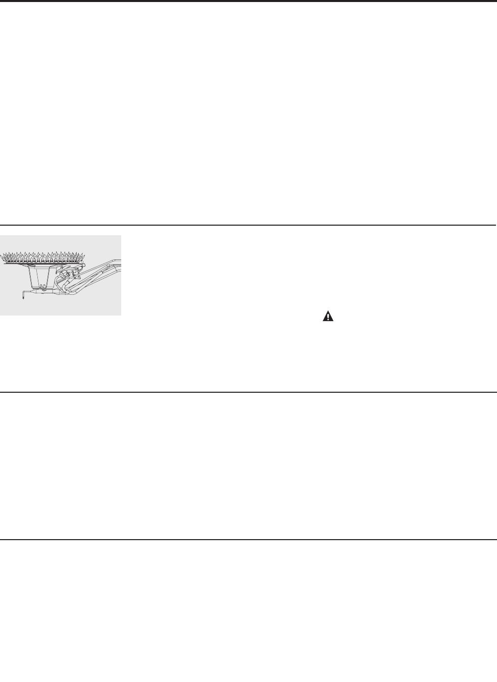
Burner Inspection
Visually inspect the burners annually.
Inspect the main burner while firing
and pilot burner flame with the main
burner off.
If any unusual burner operation is noted,
the water heater should be shut off
until qualified service assistance can be
obtained.
For cleaning, remove the burner from the
water heater. A vacuum cleaner can be
used on the burner and floor shield inside
the water heater. The burner can also be
cleaned by scrubbing with mild detergent.
CAUTION: For your safety, cleaning of
the main burner should be performed only
by qualified service personnel.
Proper burner and pilot flame
pattern.
Care and cleaning of the water heater.
Vacation and Extended Shut-Down
If the water heater is to remain idle for an
extended period of time, the power and
water to the appliance should be turned off
to conserve energy and prevent a build-up
of dangerous hydrogen gas.
The water heater and piping should be
drained if they might be subjected to
freezing temperatures.
After a long shut-down period, the water
heater’s operation and controls should be
checked by qualified service personnel.
Make certain the water heater is
completely filled again before placing
it in operation.
NOTICE: Refer to the
Hydrogen Gas Caution in the
Operating Instructions.
Anode Rod
This water heater is equipped with an
anode rod designed to prolong the life
of the glass lined tank. The anode rod
is slowly consumed cathodically, thereby
eliminating or minimizing corrosion of the
glass-lined tank.
Water sometimes contains a high
sulfate and/or mineral content and together
with cathodic protection process can
produce a hydrogen sulfide, or rotten egg
odor in the heated water. Chlorination
of the water supply should minimize the
problem.
NOTICE: Do not remove the
anode rod from the water
heater’s tank, except for
inspection and/or replacement,
as operation with the anode
rod removed will greatly
shorten the life of the glass
lined tank and will exclude
warranty coverage.
19
20
Before You Call For Service…
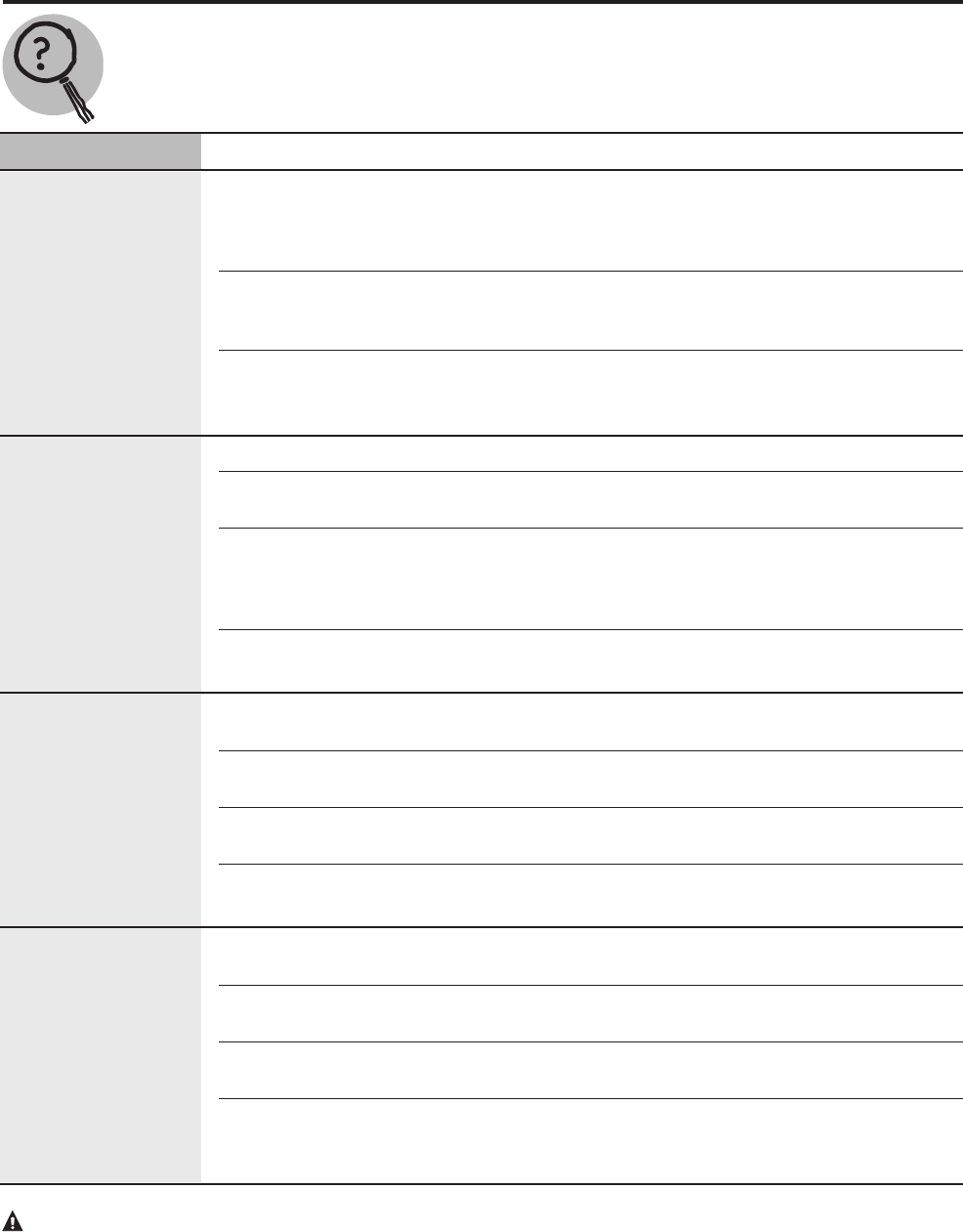
Troubleshooting Tips
Save time and money! Review the charts on the following pages first and you may not need to call for service.
Problem Possible Causes What To Do
Condensation This usually happens when ● This is normal. After the water in the tank warms
a new water heater is up the condensation will disappear. If, however, the
filled for the first time. condition persists, examine the piping and fittings
for possible leaks.
Moisture from the products ● This is normal and will disappear in time. Excessive
of combustion condensing condensation can cause pilot outage.
on the tank surface.
An undersized water ● Use a water heater size that meets the requirements
heater will cause of your needs.
condensation.
Yellow flame Scale on top of the burner. ● Shut off the water heater and remove scale.
or sooting Combustion air inlets or ● Remove lint or debris and inspect air inlet opening
flue-way restricted. for restriction.
Not enough combustion or ● Proper operation of the water heater requires air for
ventilation air supplied to combustion and ventilation. See the Combustion and
the water heater location. Ventilation Air information in the Locating the water
heater section of this manual.
Improper fuel or ● Check fuel type and Contact a qualified service
fuel conversion technician to specify fuel type.
Unable to light Gas Cock Knob not ● See the Lighting the water heater section of this
the pilot correctly positioned. manual.
Pilot orifice clogged. ● The pilot should be cleaned or replaced by a qualified
service technician.
Pilot tube pinched or ● The pilot should be cleaned, repaired or replaced by a
clogged. qualified service technician.
Air in gas line. ● Contact a qualified service technician to purge the air
from the gas line.
Pilot does not stay lit Loose thermocouple. ● The connection at the thermostat should be tightened
when the gas control by a qualified service technician.
knob is released Thermocouple breakdown. ● The thermocouple should be replaced by a qualified
service technician.
Safety magnet breakdown. ● The gas control (thermostat) should be replaced by
qualified service technician.
Gas control (thermostat) single ● The gas control (thermostat) should be replaced by a
use gas shut-off device qualified service technician.
has opened.
CAUTION: For your safety DO NOT attempt repair of gas piping, gas control (thermostat), burners,
vent connectors or other safety devices. Refer repairs to qualified service personnel.
21
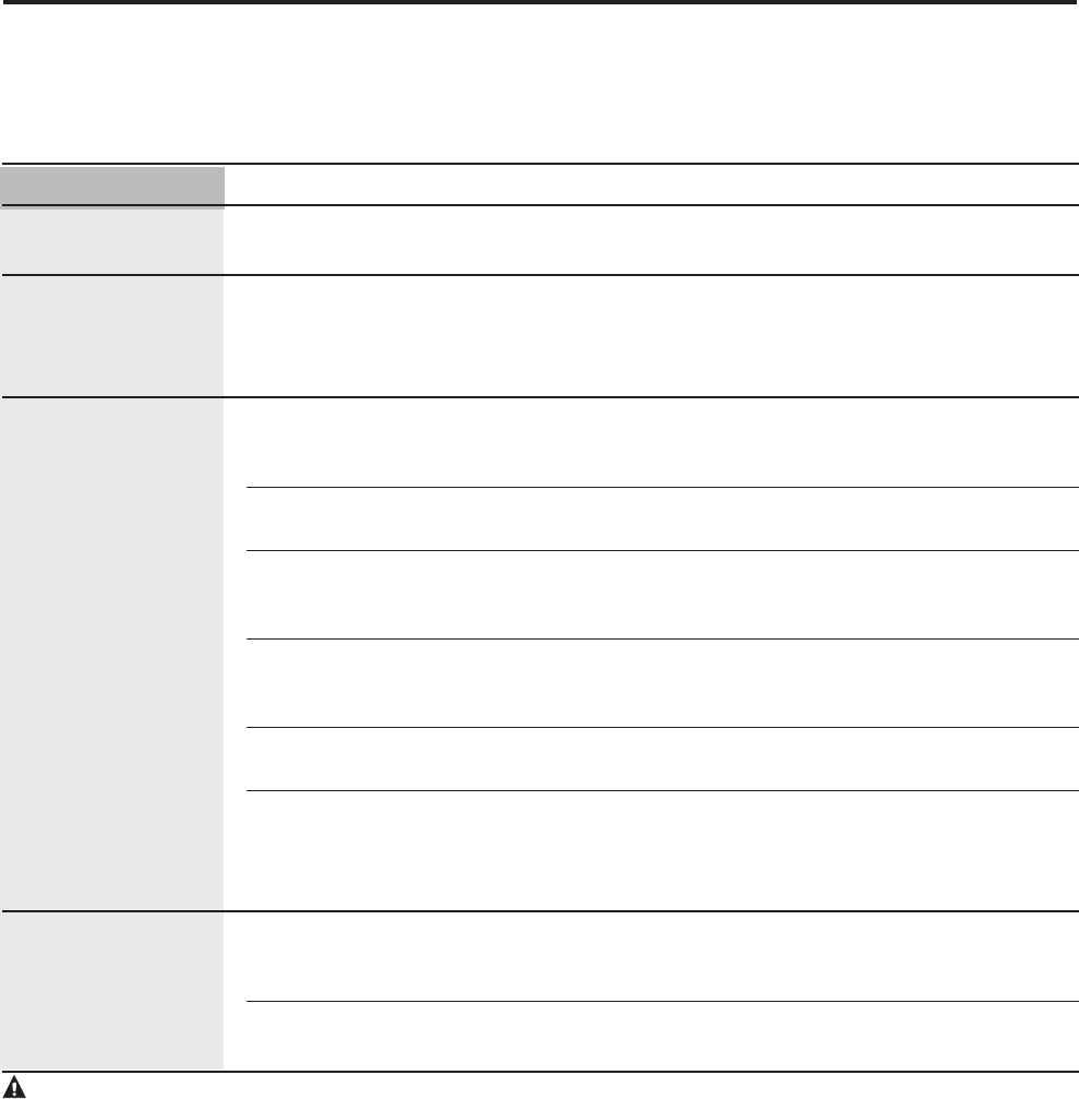
Before You Call For Service…
Problem Possible Causes What To Do
Rumbling noise Scale and sediment - Clean tank.
in tank.
Relief valve Pressure build up - This is an unacceptable condition and must be
producing popping caused by thermal corrected. Contact the water supplier or plumbing
noise or draining expansion to a contractor on how to correct this. Do not plug the
closed system. relief valve outlet.
Not enough or Water usage may have - Wait for the water heater to recover after an
no hot water exceeded the capacity abnormal demand.
of the water heater.
Low gas pressure. - Check gas supply pressure and manifold pressure.
The pilot burner may be out. - Check the pilot burner. If necessary, relight using the
instructions in the “Lighting The Water Heater”
section of this manual.
The gas control (thermostat) - See the “Water Temperature Setting” of The Water
may be set too low. Heater section of this manual.
Leaking or open hot - Make sure all faucets are closed.
water faucets.
Cold water inlet ● This is normal. The colder inlet water takes longer
temperature may be to heat.
colder during the
winter months.
Water is too hot The gas control (thermostat) ● See the “Water Temperature Setting” of The Water
is set too high. Heater section of this manual.
Gas Control (Thermostat) ● Contact a qualified service technician to replace the
Defective. gas control (thermostat).
CAUTION: For your safety DO NOT attempt repair of gas piping, gas control (thermostat), burners, vent
connectors or other safety devices. Refer repairs to qualified service personnel.
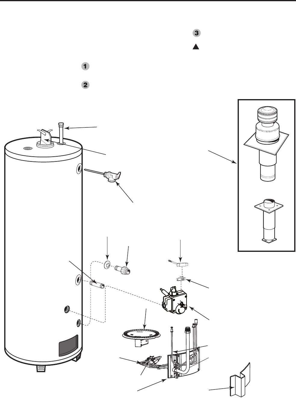
Replacement Parts.
Instructions For Placing a Parts Order
Address parts orders to the distributor
or store from where the heater was
purchased.
All parts orders should include:
The model and serial number of the
water heater from the rating plate.
Specify type of gas (natural or LP) as
marked on the rating plate.
Part description (as noted below) and
number of parts desired.
!
CAUTION: For your safety DO NOT
attempt repair of gas piping, thermostat,
burners, vent connectors or other safety devices.
Refer repairs to qualified
service personnel.
Anode Rod
T&P Relief Valve
Drain Valve
Shroud
Drain Valve
Mounting
Bracket
Piezo Ignitor
Striker
Inner Door Jacket Door
Burner
Gas Control
(Thermostat)
Pilot Assembly
Thermocouple
Burner Supply
Tube
Burner
Orice
Flue Bae
and
Hanger
Roof Jack
and
Air Inlet Assembly
Cold Inlet
Nipple
22
!
WARNING: This conversion kit must be installed by a
qualified installer or service technician in accordance with
these instructions. Installation must conform with local codes,
or in their absence, with the latest edition of the National Fuel
Gas Code, ANSI Z223.1. Failure to follow instructions could
result in serious injury or property damage. The qualified
agency performing this work assumes responsibility for this
conversion.
!CAUTION: The water heater is factory set to burn natural
gas, but can be converted to burn LP gas. Before placing the
water heater into operation, verify that the type of gas
supplied to your water heater and the type of gas your water
heater is set to burn are the same. If they are not, refer to
these instructions.
NOTICE: The parts required to make this conversion are supplied
in a bag attached to the water heater. Should your heater not have
this bag attached to the water heater, a replacement can be obtained.
Simply contact the manufacturer at the address below and request a
replacement conversion kit.
Customer Service Department
2600 Gunter Park Drive, East
Montgomery, AL 36109-1413
Phone: 1-800-432-8373
Tools Required:
#2 Phillips Screwdriver
3/4" Wrench
7/16" Wrench
3/8" Wrench
5/16" Wrench
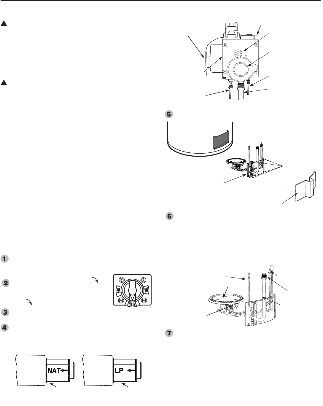
Turn manual gas shut off valve to the OFF position to shutoff gas
to the thermostat.
Set the thermostat dial to the lowest setting by
turning the thermostat dial clockwise until
it stops. DO NOT FORCE.
Slightly depress the gas control knob and turn
clockwise to "OFF" position. Note: Knob
cannot be turned from "PILOT" position
unless pushed down slightly. DO NOT USE FORCE.
Change gas regulators setting by removing cover from the gas
selector screw; then remove and reinstall the selector screw with
the red washer and LP arrow mark pointing inward toward the
heater. Tighten to 4-8 in-lb. Replace cover.
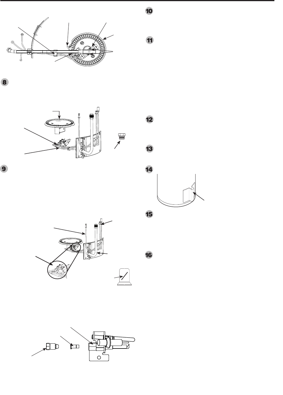
Remove outer jacket door.
Remove the six phillips screws on the inner door using a phillips
screwdriver. Disconnect burner supply tube using the 3/4" wrench,
pilot tube using the 7/16" wrench, and thermocouple using the 3/8"
wrench from the thermostat. Disconnect the piezo wire from piezo
ignitor striker connection. Remove the entire burner assembly
along with the inner door.Remove the phillips head screw that holds
the pilot burner assembly in place.
Remove the phillips head screw that holds the pilot burner
assembly in place. Remove the pilot burner assembly from the
burner bracket. Remove the two #6 x 3/8" long Philips head screws
from the burner bracket and remove the burner from inner door
assembly to expose main burner orifice.
Conversion instructions—Natural Gas to LP Gas
If your gas supply is LP gas, your water heater can be converted to burn LP gas as follows:
Natural Gas to Liquefied Petroleum (LP or Propane) Gas
23
Inner Door
Assembly
Outer Jacket Door
Phillips Head
Screws
Gas Selector Screw
(Without cover.)
Thermostat Dial
Gas Thermostat
Front View of Gas Thermostat
Piezo Wire Connection
Thermocouple
(Copper Tube)
Pilot Tube
(1/8" Aluminum Tube)
Burner Supply Tube
Piezo Igniter Striker
Burner Supply
Tube
Pilot
Burner
Thermocouple
Pilot Burner
Piezo Wire
LP Gas Position
Natural Gas Position
Gas Selector Screw Settings
Blue Washer Red Washer
24
Conversion Instructions—Natural Gas to LP Gas
Remove main burner orifice. Replace main burner
natural gas orifice with the Red colored main
burner orifice (stamped LP) supplied in the bag.
Remove the compression nut from the pilot burner
assembly using the 3/8" and 5/16" wrench to expose
pilot burner orifice. Remove natural gas pilot burner
orifice and replace with Yellow marked LP pilot
burner orifice supplied in the package. Replace the
compression nut on pilot burner assembly and tighten the
nut.
Reinstall the main burner with the two #6 x 3/8" long
Phillips head screws. Screw the pilot burner assembly
to the burner bracket using the Phillips head screw
removed on step 7.
Clean the metal surfaces to assure proper sealing
of gasket. Reinstall entire inner door assembly to
the heater. Align screwholes of gasket with holes
on inner door and then attach inner door loosely
to the heater using all six Phillips head screws.
Reconnect and tighten burner supply, pilot tube
and thermocouple at the thermostat. Handle tubes
carefully to avoid damaging them. DO NOT over-
tighten or cross-thread the connections. Now tighten
all the phillips head screws to secure the inner door
firmly to the heater. Reconnect the piezo wire to the
piezo ignitor striker connection.
Attach green CAUTION label from the bag to the
outside of the water heater near the gas control. Label
should be signed by qualified installer or service
organization
Return the unused parts to the bag for possible future
conversions. Return the bag and this Use and Care
manual to the plastic bag attached to the water heater.
Install outer jacket door to heater.
Turn manual gas shut off valve to the ON position
to start gas flow to the thermostat. Leak test all
gas connections and caps with soap/water solution.
Bubbles indicate a leak. Make certain all leaks have
been repaired, and the outer jacket door has been
replaced.
Follow lighting instructions on page 15 of the manual
to start the water heater.
Pilot Screw
#6 x 3/8" long
screws
Burner
Bracket
Pilot
Bottom View of Inner Door Assembly
Clip
Exploded View of Pilot Burner Assembly
Pilot Burner Assembly
Pilot Burner Orice
Compression Nut
Jacket door
Burner supply
tube
Thermocouple
Pilot tube
Pilot Burner
Assembly
Pilot burner orifice
Yellow mark
indicates LP gas
orifice
Main Burner
orifice
Burner supply
tube
Burner
Main burner orifice
(stamped LP)
Red color indicates
LP gas orifice
Conversion instructions—LP Gas to Natural Gas
Your water heater was factory pre-set to burn natural gas but may have been converted to burn LP gas. If your water heater
has been converted to burn LP Gas, and your gas supply is now natural gas, your water heater can be converted to burn
natural gas as follows:
WARNING: This conversion kit must be installed by a
qualified installer or service technician in accordance with
these instructions. Installation must conform with local
codes, or in their absence, with the latest edition of the
National Fuel Gas Code, ANSI Z223.1. Failure to follow
instructions could result in serious injury or property
damage. The qualified agency performing this work assumes
responsibility for this conversion.
CAUTION: The water heater is factory set to burn
natural gas, but can be converted to burn LP gas. Before
placing the water heater into operation, verify that the type
of gas supplied to your water heater and the type of gas your
water heater is set to burn are the same. If they are not, refer
to these instructions.
NOTICE: The parts required to make this conversion are supplied
in a bag attached to the water heater. Should your heater not
have this bag attached to the water heater, a replacement can be
obtained. Simply contact the manufacturer at the address below
and request a replacement conversion kit.
Customer Service Department
2600 Gunter Park Drive, East
Montgomery, AL 36109-1413
Phone: 1-800-432-8373
Tools Required:
#2 Phillips Screwdriver
3/4" Wrench
7/16" Wrench
3/8" Wrench
5/16" Wrench
Turn manual gas shut off valve to the OFF position to shutoff gas
to the thermostat.
Set the thermostat dial to the lowest setting
by turning the thermostat dial clockwise
until it stops. DO NOT FORCE.
Slightly depress the gas control knob and
turn clockwise to "OFF" position. Note:
Knob cannot be turned from "PILOT"
position unless pushed down slightly. DO NOT USE FORCE.
Change gas regulator setting by removing cover from the gas
selector screw; then remove and reinstall the selector screw with
the blue washer and NAT arrow mark pointing inward toward the
heater. Tighten to 4-8 in lb. Replace cover.
Remove outer jacket door.
Remove the six phillips head screws on the inner door using the
phillips screwdriver. Disconnect burner supply tube using the 3/4"
wrench, pilot tube using the 7/16" wrench, and thermocouple
using the 3/8" wrench from the thermostat. Disconnect the piezo
wire from piezo ignitor striker connection. Remove the entire
burner assembly along with the inner door.
Remove the philips head screw that holds the pilot burner
assembly in place. Remove the pilot burner assembly from the
burner bracket. Remove the two #6 x 3/8" long philips head
screws from the burner bracket and remove the burner from inner
door assembly to expose main burner orifice.
Liquefied Petroleum (LP or Propane) to Gas Natural Gas
Gas Selector Screw
(Without cover.)
Thermostat Dial
Gas Thermostat
Piezo Wire Connection
Thermocouple
(Copper Tube)
Pilot Tube
(1/8" Aluminum Tube)
Burner Supply Tube
Piezo Igniter Striker
Front View of Gas Thermostat
Inner Door
Assembly
Outer Jacket Door
Phillips Head
Screws
Burner Supply
Tube
Pilot
Burner
Thermocouple
Pilot Burner
Piezo Wire
25
LP Gas Position
Natural Gas Position
Gas Selector Screw Settings
Blue Washer Red Washer
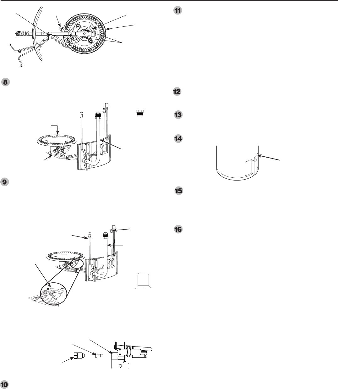
26
Conversion instructions—LP Gas to Natural Gas
Remove LP burner orifice. Replace Red marked LP gas
burner orifice with the main burner orifice stamped NG
supplied in the bag.
Remove the compression nut from the pilot burner assembly
using the 3/8” and 5/16” wrench to expose pilot burner
orifice. Remove the yellow marked LP gas pilot burner
orifice and replace with natural gas pilot burner orifice
supplied in the package. Replace the compression nut on
pilot burner assembly and tighten the nut.
Reinstall the main burner with the two #6 x 3/8" long
phillips head screws. Screw the pilot burner assembly to the
burner bracket using the Phillips head screw removed on
step 7.
Clean the metal surfaces to assure proper sealing of gasket.
Reinstall entire inner door assembly to the heater. Align
screwholes of gasket with holes on inner door and then
attach inner door loosely to the heater using all six Phillips
head screws. Reconnect and tighten burner supply, pilot
tube and thermocouple at the thermostat. Handle tubes
carefully to avoid damaging them. DO NOT over-tighten
or cross-thread the connections. Now tighten all the
phillips head screws to secure the inner door firmly to the
heater. Reconnect the piezo wire to the piezo ignitor striker
connection.
Attach green CAUTION label from the bag to the outside of
the water heater near the gas control. Label should be signed
by qualified installer or service organization.
Return the unused parts to the bag for possible future
conversions. Return the bag and this Use and Care manual to
the plastic bag attached to the water heater.
Install outer jacket door to heater.
Turn manual gas shut off valve to the ON position to start
gas flow to the thermostat. Leak test all gas connections and
caps with soap/water solution. Bubbles indicate a leak. Make
certain all leaks have been repaired, and the outer jacket
door has been replaced.
Follow lighting instructions on page 15 of the manual to start
the heater.
Pilot Burner Assembly
Pilot Burner Orice
Compression Nut
Pilot
#6 x 3/8" long
screws
Burner
Bracket
Pilot Screw
Bottom View of Inner Door Assembly
Clip
Burner orifice
Burner supply
tube
Burner Main burner orifice
(stamped NG)
Pilot tube
Burner supply
tube
Thermocouple
Pilot Burner
Assembly
Exploded View of Pilot Burner Assembly
Jacket door
Natural Gas Pilot
burner orifice

27
Notes:
28
IF YOU NEED SERVICE
1. Should you have any questions about your new water heater, or if it requires
adjustment, repair, or routine maintenance, it is suggested that you first contact
your installer, plumbing contractor or previously agreed upon service agency. In
the event the firm has moved, or is unavailable, refer to the telephone directory,
commercial listings or local utility for qualified service assistance.
2. Should your problem not be solved to your complete satisfaction, you should
then contact the Manufacturer’s National Service Department at the following
address:
2600 Gunter Park Drive
Montgomery, Alabama 36109-1413
Phone: 1-800-432-8373.
When contacting the manufacturer, the following information will be requested:
a. Model and serial number of the water heater as shown on the rating plate attached
to the front panel of the heater.
b. Address where the water heater is located and physical location.
c. Name and address of installer and any service agency who performed service on
the water heater.
d. Date of original installation and dates any service work was performed.
e. Details of the problem as you can best describe them.
f. List of people, with dates, who have been contacted regarding your problem.
