Rhodan Marine Systems RMS-FOB1 Anchor Fob 1 User Manual
Rhodan Marine Systems, Inc. Anchor Fob 1 Users Manual
Users Manual
OWNER’S MANUAL
Wireless Remote Control
GPS Guided Trolling Motor
Model GPS-W-BM-80-54
or
Model GPS-W-BM-80-60
Rhodan Marine Systems
8274 Blaikie Court
Sarasota, Florida
1-800-RHODAN1

RHODAN HDGPS ANCHOR+
Rhodan Marine Systems, Inc. 8274 Blaikie Ct. Sarasota, FL 34240 (941)706-4578
Page 2 of 26
Congratulations on choosing this unique product. The
Rhodan Marine Systems HDGPS ANCHOR+should dramatically add
to your angling enjoyments.
Powerful and quiet, this precision engineered product will
automatically keep your fishing boat positioned at your chosen
fishing spot or at your command, maintain the boat on a chosen
trolling path, leaving you free to concentrate on the fishing.
Note: This model is designed for use on 17 to 21 foot sport fishing boats. It
may be too powerful for smaller boats and may not have sufficient power for
larger boats.
Model GPSGW-BM-80 Specifications
Thrust rating
Operating Voltage
Amperage
Propeller
Shaft Length
80 pounds
24 Volts DC
50 Amps Max
3-Blade Weedless
60” (-60) or 54 “ (–54)

RHODAN HDGPS ANCHOR+
Rhodan Marine Systems, Inc. 8274 Blaikie Ct. Sarasota, FL 34240 (941)706-4578
Page 3 of 26
FCC Compliance Statement
FCC ID: XA7-RMS-FOB1
FCC NOTICE: This equipment has been tested and found to comply with the limits for a
class B digital device, pursuant to part 15 of the FCC Rules. These limits are designed to
provide reasonable protection against harmful interference in a residential installation. This
equipment generates, uses and can radiate radio frequency energy and if not installed and
used in accordance with the instructions, may cause harmful interference to radio
communications. However, there is no guarantee that interference will not occur in a
particular installation. If this equipment does cause harmful interference to radio or
television reception, which can be determined by turning the equipment off and on, the user
is encouraged to try to correct the interference by one or more of the following measures:
• Reorient or relocate the receiving antenna.
• Increase the separation between the equipment and receiver.
• Connect the equipment into an outlet on a circuit different from that to which the receiver
is connected.
• Consult the dealer or an experienced radio/TV technician for help.
• It is strongly recommended that the TV be plugged into a separate wall outlet.
This equipment has been verified to comply with the limits for a class B computing device,
pursuant to FCC Rules. In order to maintain compliance with FCC regulations, shielded
cables must be used with this equipment. Operation with non-approved equipment or
unshielded cables is likely to result in interference to radio and TV reception.
The user is cautioned that changes and modifications made to the equipment without the
approval of manufacturer could void the user’s authority to operate this equipment.
This device complies with Part 15 of the FCC Rules. Operation is subject to the following
two conditions: (1) this device may not cause harmful interference, and (2) this device must
accept any interference received, including interference that may cause undesired
operation.

RHODAN HDGPS ANCHOR+
Rhodan Marine Systems, Inc. 8274 Blaikie Ct. Sarasota, FL 34240 (941)706-4578
Page 4 of 26
TABLE OF CONTENTS
SYSTEM FEATURES__________________________________________5
GETTING STARTED__________________________________________6
DEPLOYING THE UNIT_______________________________________7
STOWING THE UNIT_________________________________________8
WIRELESS CONTROL________________________________________9
MODES OF OPERATION______________________________________10
MANUAL MODE________________________________________11
ANCHOR MODE________________________________________12
TRACKING MODE______________________________________13
APPENDIX A: INSTALLATION PROCEDURES__________________14
MECHANICAL INSTALLATION PROCEDURE____________15-17
ELECTRICAL INSTALLATION PROCEDURES____________ 18-19
PROPELLER INSTALLATION____________________________20
APPENDIX B: SYSTEM CALIBRATIONS________________________21
APPENDIX C: MAINTENANCE AND STORAGE__________________22
REPLACING WIRELESS FOBS_________________________________23
TROUBLE SHOOTING________________________________________24
WARRANTY AND CUSTOMER SUPPORT_______________________25
WARRANTY AND CUSTOMER SUPPORT_______________________25
CUSTOMER NOTES___________________________________________26
RHODAN HDGPS ANCHOR+
Rhodan Marine Systems, Inc. 8274 Blaikie Ct. Sarasota, FL 34240 (941)706-4578
Page 5 of 26
Installation procedures will be found in appendix
A.
Please follow them carefully.
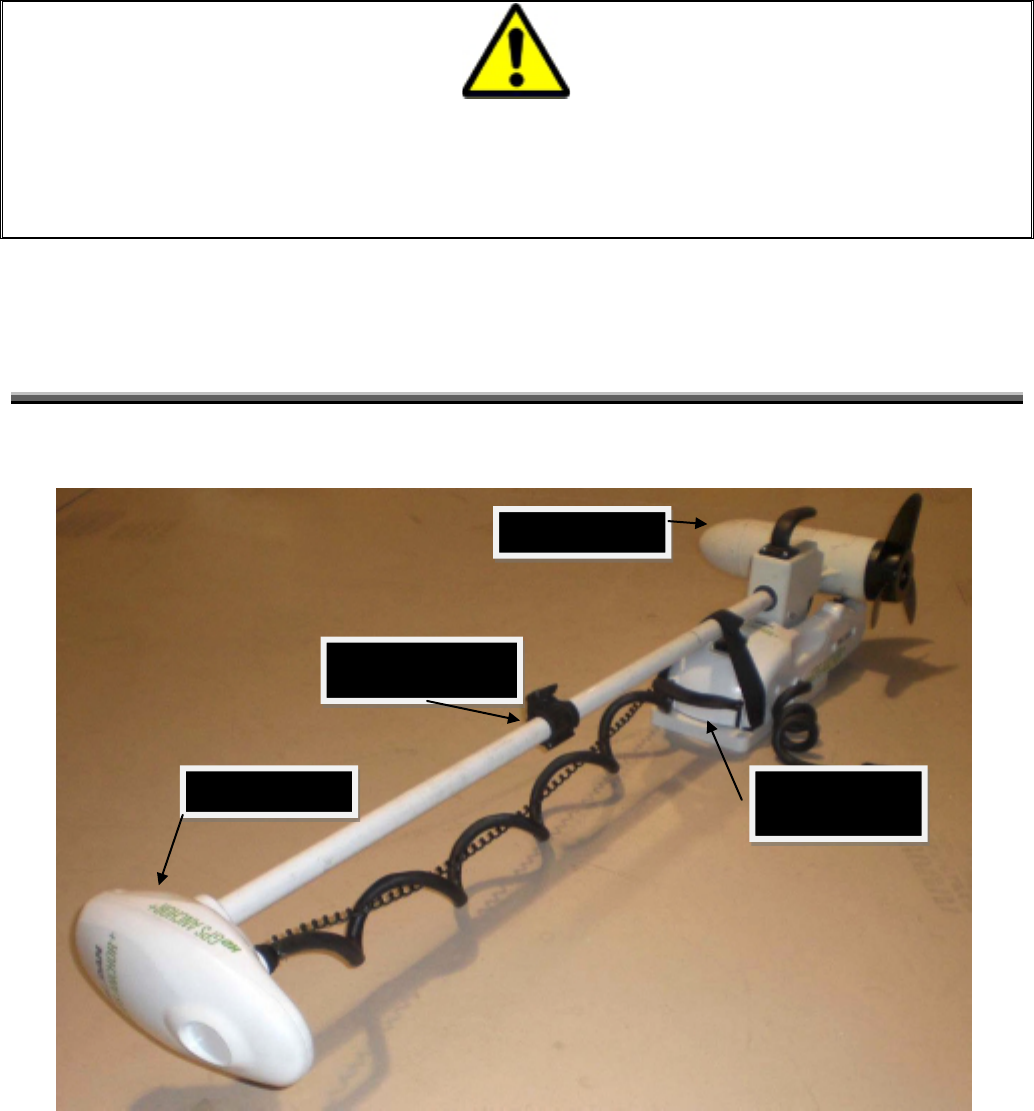
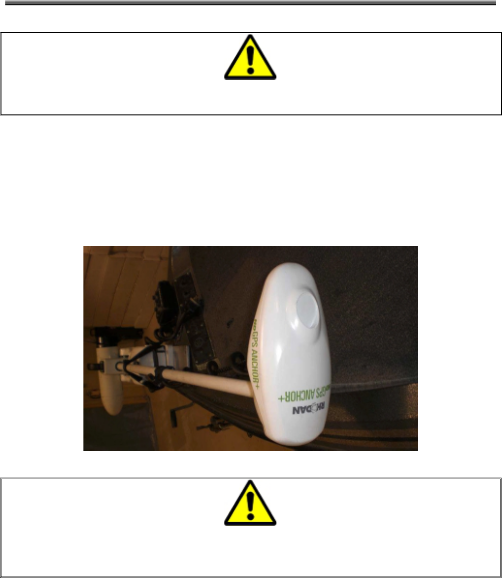
SYSTEM FEATURES
TOP HOUSING TILT/LOCK
LEVER
DEPTH ADJUST
COLLAR
LOWER UNIT
RHODAN HDGPS ANCHOR+
Rhodan Marine Systems, Inc. 8274 Blaikie Ct. Sarasota, FL 34240 (941)706-4578
Page 6 of 26
GETTING STARTED
The GPS ANCHOR requires the use of a wireless remote control fob for user
control. Please refer to the Wireless Control section for additional
information.
It is recommended that you apply power to the GPS ANCHOR early in the
trip so that the embedded GPS unit can obtain a navigation fix and
download an up-to-date satellite almanac.
The system is equipped with a “Tilt” sensor that prevents the propeller from
running in the stowed position.
The system will operate in Manual Mode immediately when powered up and
deployed. The Anchor Mode and Tracking Mode will be available after
approximately 30 seconds allowing the unit to acquire a GPS fix.
The unit will emit 4 rapid “beeps” to indicate that it has acquired a
GPS fix
.
The unit will achieve its maximum accuracy after approximately 15 minutes
once the GPS has downloaded a new satellite almanac.
RHODAN HDGPS ANCHOR+
Rhodan Marine Systems, Inc. 8274 Blaikie Ct. Sarasota, FL 34240 (941)706-4578
Page 7 of 26
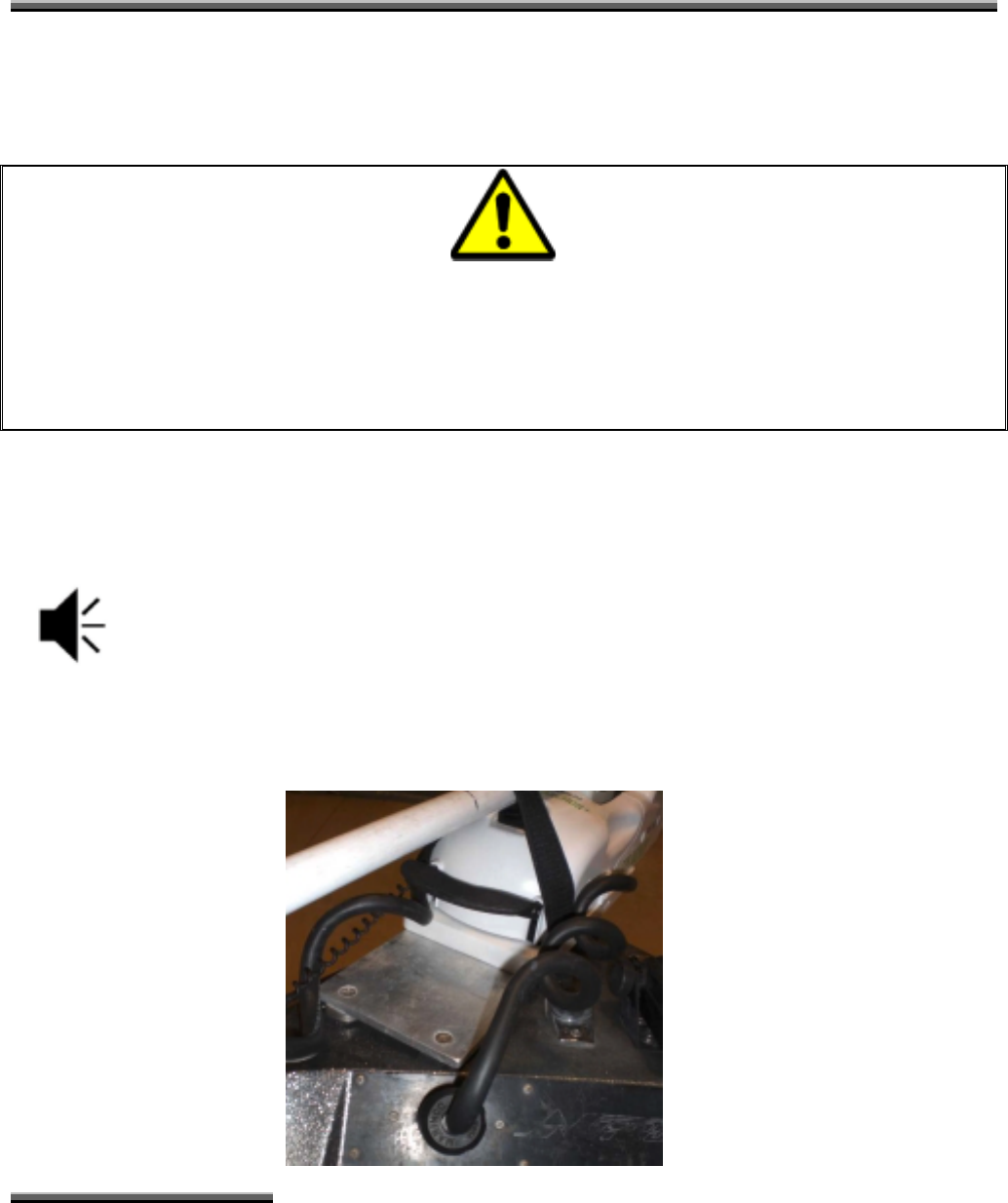
DEPLOYING THE UNIT
Release the Velcro-safety strap and step on the Tilt/Lock lever to release
the locking collar. Slide the motor forward until the lower unit is out of the
mounting bracket.
Carefully tilt the unit forward and lower the motor to the desired depth
(about one foot below the surface). The motor should be pointed dead ahead
with the prop to the facing the boat’s stern. Release the Tilt/Lock Lever.
Verify that unit is securely latched in the deployed position with the
Tilt/Lock Lever
Slide the depth-adjusting collar down the shaft until engaged with the
steering mechanism then hand tighten the adjusting knob to secure the
unit.
RHODAN HDGPS ANCHOR+
Rhodan Marine Systems, Inc. 8274 Blaikie Ct. Sarasota, FL 34240 (941)706-4578
Page 8 of 26
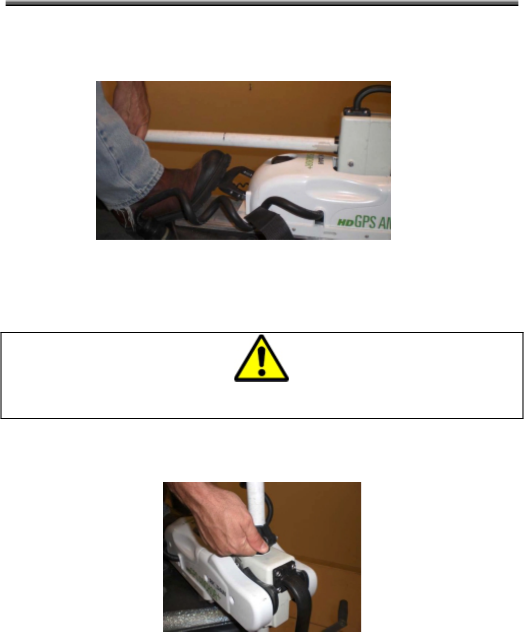
STOWING THE UNIT
Always stow the GPS ANCHOR properly on the deck in its latched horizontal
position when not in use.
Step on the Tilt/Lock Lever. Grasping the head of the unit, pull it up and
towards the boat’s stern until the bottom unit rests securely on the ramp.
Release the Tilt/Lock Lever and ensure that it has snapped into place. Use
the Velcro safety strap to secure it in place.
Verify that unit is securely latched in the stowed position with the Tilt/Lock
Lever. The system will automatically turn off all motors and will not respond
to wireless remote commands when stowed.
RHODAN HDGPS ANCHOR+
Rhodan Marine Systems, Inc. 8274 Blaikie Ct. Sarasota, FL 34240 (941)706-4578
Page 9 of 26
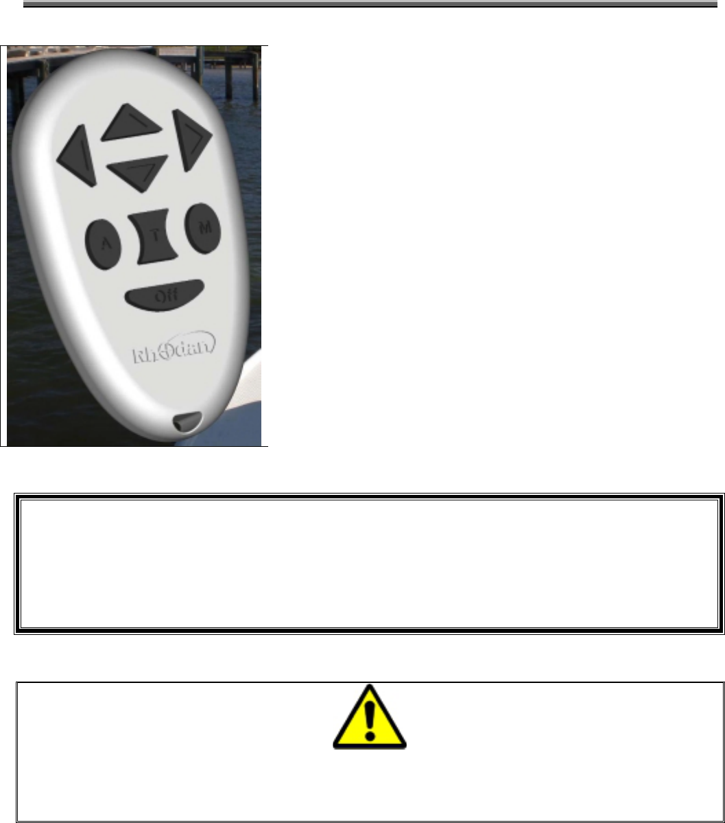
WIRELESS CONTROL
The HD GPS ANCHOR+ is controlled
wirelessly using the 8 buttons on the
included Remote Control fobs.
(4) Buttons are directional controls.
These buttons can be identified as the
up, down, left, and right arrows. See
the table below for more information
(3) Buttons are used to dictate the
system mode. The “M” button selects
Manual Mode, the “A” button selects
Anchor Mode, and the “T” button
selects Tracking Mode.
The “Off” button cancels any previous
mode selection and zeroes the thrust.
D
D
i
i
r
r
e
e
c
c
t
t
i
i
o
o
n
n
a
a
l
l
C
C
o
o
n
n
t
t
r
r
o
o
l
l
B
B
u
u
t
t
t
t
o
o
n
n
F
F
u
u
n
n
c
c
t
t
i
i
o
o
n
n
s
s
SEE “OPERATIONAL MODES” SECTION FOR MORE INFORMATION
Manual Mode Steer unit & Increase/Decrease thrust
Anchor Mode Jog anchor site in 5-foot increments
Tracking Mode Adjust GPS Track & Increase/Decrease thrust
The Remote Control Fob is designed to float but it is recommended that it
be used with the supplied lanyard to minimize the risk of loss or damage
due to dropping. Refer to Appendix C if replacing a fob.

RHODAN HDGPS ANCHOR+
Rhodan Marine Systems, Inc. 8274 Blaikie Ct. Sarasota, FL 34240 (941)706-4578
Page 10 of 26
MODES OF OPERATION
The three modes of operation are as follows:
1)Manual Mode
2)Anchor Mode
3)Tracking Mode
N
N
o
o
t
t
e
e
:
:
The “Off button” will re-center the steering and reduce the trolling
motor propeller speed to zero.
The following pages describe the Operational Modes of the
HD
GPS ANCHOR
+
.
It is recommended that all system operators review this manual in its
entirety prior to use.
Any mode may be entered at any time while operating the unit in the
deployed position. Verify that the unit is securely locked into position
before using. Refer to the “Deploying the Unit” section for more information.
Securely stow the unit when not in use. Refer to the “Stowing the Unit”
section for more information. The system will automatically turn off all
motors and will not respond to wireless remote commands when stowed.
RHODAN HDGPS ANCHOR+
Rhodan Marine Systems, Inc. 8274 Blaikie Ct. Sarasota, FL 34240 (941)706-4578
Page 11 of 26
MANUAL MODE
In the Manual Mode the GPS ANCHOR behaves much like a conventional
trolling motor.
The Manual Mode allows the user to control the trolling motor’s direction
and thrust level using the directional controls on the wireless fob. To place
the system in Manual Mode, press the button with the “M” symbol on the
wireless fob.
The unit will emit 1 “beep” to indicate that it has entered Manual
Mode
.
FORWARD OPERATION
Pressing the Up-Arrow button when the unit is stopped places the unit in
“Forward” and begins to increase the thruster’s forward speed. The Down-
Arrow button decreases the thruster’s forward speed.
The unit will “beep” when the thruster reaches 100% forward speed
or when it is stopped.
REVERSE OPERATION
Pressing the Down-Arrow button when the unit is stopped places the unit in
“Reverse” and begins to increase the thruster’s reverse speed. The Up-
Arrow button decreases the thruster’s reverse speed.
The unit will “beep” when the thruster reaches 100% reverse speed
or when it is stopped.
STEERING
Pressing the Left-Arrow and Right-Arrow buttons cause the trolling motor to
turn left or right respectively. The steering travel is limited to avoid
wrapping up the system power cord.
RHODAN HDGPS ANCHOR+
Rhodan Marine Systems, Inc. 8274 Blaikie Ct. Sarasota, FL 34240 (941)706-4578
Page 12 of 26
ANCHOR MODE
The Anchor Mode automatically controls the steering and thruster speed to
maintain the position of the boat’s bow, acting as a “Virtual Anchor”. The
operator can easily move the “Anchor Location”by using the directional
controls on the wireless fob. To place the system in Anchor Mode, press the
button with the “A” symbol on the wireless fob.
The unit will emit 1 “beep” to indicate that it has entered Anchor
Mode
.
The unit will emit 2 “beeps” and exit this mode if there is no
GPS fix.
N
N
o
o
t
t
e
e
:
:
The boat will slowly swing downwind or down current and go into
trail with the bow generally pointed into the disturbing wind or current.
Slowly approaching the desired location from downwind or down current
prior to pressing the Anchor button is recommended.
M
M
O
O
V
V
I
I
N
N
G
G
“
“
J
J
O
O
G
G
G
G
I
I
N
N
G
G
”
”
T
T
H
H
E
E
A
A
N
N
C
C
H
H
O
O
R
R
L
L
O
O
C
C
A
A
T
T
I
I
O
O
N
N
Pressing any of the directional controls on the wireless fob (Up, Down, Left,
or Right) moves the “Anchor Location” in 5-foot increments relative to the
boat’s heading. For example, pressing the Up-Arrow once moves the
“Anchor Location” 5-feet out in front of the boat’s bow.
The unit will emit 1 “beep” each time the Anchor location is moved
The embedded system computer will be operating the trolling motor causing
the bow of the boat to move as needed to maintain its location in this mode.
Unexpected movement of the boat may tend to unbalance you.
Be cautious until you have become familiar with the system dynamics.
RHODAN HDGPS ANCHOR+
Rhodan Marine Systems, Inc. 8274 Blaikie Ct. Sarasota, FL 34240 (941)706-4578
Page 13 of 26
TRACKING MODE
The Tracking Mode automatically controls the steering to maintain a
constant course track, acting as an “Autopilot”. The operator can adjust the
speed or track heading by using the directional controls on the wireless fob.
To place the system in Tracking Mode, press the button with the “T” symbol
on the wireless fob.
The unit will emit 1 “beep” to indicate that it has entered Tracking
Mode. The unit will emit 2 “beeps” and exit this mode if there is no
GPS fix.
N
N
o
o
t
t
e
e
:
:
The direction the boat is pointed when this mode is selected will
become the “Tracking Course”. The thruster will pull the bow of the boat
along this course in a straight line. The boat itself may seem to point
somewhat “off track” due to cross-wind or cross-track currents.
A
A
D
D
J
J
U
U
S
S
T
T
I
I
N
N
G
G
T
T
H
H
E
E
T
T
R
R
A
A
C
C
K
K
I
I
N
N
G
G
S
S
P
P
E
E
E
E
D
D
The unit will maintain its previous speed if Tracking Mode is selected while
the unit is in Manual Mode. Otherwise, the unit will gradually ramp to 50%
forward speed to maintain the track. Pressing the Up-Arrow button
increases the thruster’s forward speed. The Down-Arrow button decreases
the thruster’s forward speed. Reverse operation is disabled in this mode.
The unit will “beep” when the thruster reaches 100% forward speed
or when it is stopped.
A
A
D
D
J
J
U
U
S
S
T
T
I
I
N
N
G
G
T
T
H
H
E
E
T
T
R
R
A
A
C
C
K
K
I
I
N
N
G
G
C
C
O
O
U
U
R
R
S
S
E
E
The “Tracking Course” may be adjusted in 10-degree increments by pressing
the Left or Right Arrow buttons on the wireless fob.
Speed may need to be increased to overcome cross-winds and cross-
currents to stay “on-track”

RHODAN HDGPS ANCHOR+
Rhodan Marine Systems, Inc. 8274 Blaikie Ct. Sarasota, FL 34240 (941)706-4578
Page 14 of 26
APPENDIX A
INSTALLATION PROCEDURE
REFER TO APPENDIX B AFTER SYSTEM INSTALLATION FOR
RECOMMENDED CALIBRATION PROCEDURES
The GPS-W-80 model has been designed for use on 16 to 21 foot sport
fishing boats. Boats larger than 21-feet may require higher thrusting motors.
Installations on boats smaller than 16-feet may result in overly aggressive
movements which can lead to injury or even death.
It is recommended that a trained technician install the GPS Anchor. Contact
Rhodan Marine Systems for a list of approved installers. Improper
installation can lead to injury or even death. It is the responsibility of the
installer to verify proper installation.
DO NOT cnnect the
HD
GPS ANCHOR
+
to a power source until installation is
completed.
The
HD
GPS ANCHOR
+
utilizes sensors which can be affected by nearby
magnetic fields. DO NOT install unit with or near anything that produces a
magnetic field (steel, magnets, etc.)
RHODAN HDGPS ANCHOR+
Rhodan Marine Systems, Inc. 8274 Blaikie Ct. Sarasota, FL 34240 (941)706-4578
Page 15 of 26
M
M
e
e
c
c
h
h
a
a
n
n
i
i
c
c
a
a
l
l
I
I
n
n
s
s
t
t
a
a
l
l
l
l
a
a
t
t
i
i
o
o
n
n
P
P
r
r
o
o
c
c
e
e
d
d
u
u
r
r
e
e
s
s
:
:
1
1
)
)
R
R
e
e
m
m
o
o
v
v
e
e
t
t
h
h
e
e
P
P
l
l
a
a
s
s
t
t
i
i
c
c
S
S
i
i
d
d
e
e
P
P
a
a
n
n
e
e
l
l
s
s
:
:
a. Each panel is secured with (2) #3 Phillips stainless steel screws.
b. Remove the screws and panels then set them aside.
2
2
)
)
R
R
e
e
m
m
o
o
v
v
e
e
t
t
h
h
e
e
R
R
e
e
a
a
r
r
P
P
l
l
a
a
s
s
t
t
i
i
c
c
C
C
o
o
v
v
e
e
r
r
:
:
a. The rear cover is secured using (2) #3 Phillips stainless steel
machine screws.
b. Remove the screws and gently lift the cover off being careful not to
damage the black cable between the cover and the black
encapsulated computer module.
c. If connected, unscrew the black cable from the computer module by
grasping the gold connector and rotating counter-clockwise.
d. Set the cover aside.
Take care to not damage the black cable during this process!
3
3
)
)
D
D
e
e
t
t
e
e
r
r
m
m
i
i
n
n
e
e
t
t
h
h
e
e
M
M
o
o
u
u
n
n
t
t
i
i
n
n
g
g
P
P
l
l
a
a
t
t
e
e
P
P
o
o
s
s
i
i
t
t
i
i
o
o
n
n
:
:
a. STOWED POSITION: Verify that the trolling motor head and shaft do
not block any more deck area then necessary. The mounting plate
is typically mounted about 30 degrees on the “port” side of the
vessel.
b.
DEPLOYED POSITION: Verify that the shaft is vertical and as near
the centerline of the boat. Ensure that there is ample clearance
between the shaft and the bow when the unit is in the deployed
position (1-2”).
c. Mark the location of (4) mount holes using the mounting plate as a
template. Remove the unit from the boat’s deck and set aside.

RHODAN HDGPS ANCHOR+
Rhodan Marine Systems, Inc. 8274 Blaikie Ct. Sarasota, FL 34240 (941)706-4578
Page 16 of 26
Verify that the mounting hole locations are placed in a location on the deck
with enough room to install the mounting screws and washers without
penetrating the hull.
4
4
)
)
D
D
r
r
i
i
l
l
l
l
M
M
o
o
u
u
n
n
t
t
i
i
n
n
g
g
H
H
o
o
l
l
e
e
s
s
:
:
a. Use a 5/16” (8mm) drill bit to drill through the deck at each
mounting hole location.
b. Clear the holes of any debris.
Rhodan Marine recommends using trolling motor isolation bolts. Verify that
hole is large enough to accommodate isolation bolts if used.
5
5
)
)
F
F
a
a
s
s
t
t
e
e
n
n
t
t
h
h
e
e
M
M
o
o
u
u
n
n
t
t
i
i
n
n
g
g
P
P
l
l
a
a
t
t
e
e
t
t
o
o
t
t
h
h
e
e
B
B
o
o
a
a
t
t
:
:
a. If isolation bolts are used, push (4) isolation nuts through each of
the mounting holes.
b. Place the trolling motor back on the deck and align the holes on the
mounting plate with the holes (isolation nuts) on the deck.
c. Install the (4) stainless steel bolts through each mounting hole
(isolation nut) using a #3 phillips screwdriver.
d. If isolation bolts are NOT used, install (4) stainless steel washers
and nuts on the bottom side of the deck.
e. Tighten each bolt securely.
6
6
)
)
R
R
e
e
i
i
n
n
s
s
t
t
a
a
l
l
l
l
t
t
h
h
e
e
P
P
l
l
a
a
s
s
t
t
i
i
c
c
C
C
o
o
v
v
e
e
r
r
s
s
:
:
a. Reconnect the black cable on the Rear Plastic Cover to the
computer module by screwing the cable’s gold connector onto the
module’s gold connector. Hand tighten the connection.
b. Reinstall the Rear Plastic Cover on the trolling motor being careful
to not damage any of the wires.
RHODAN HDGPS ANCHOR+
Rhodan Marine Systems, Inc. 8274 Blaikie Ct. Sarasota, FL 34240 (941)706-4578
Page 17 of 26
c. Secure the cover onto the motor using the (2) #3 Phillips stainless
steel machine screws.
d. Reinstall the (2) plastic side panels. Each panel is secured with (2)
#3 Phillips stainless steel machine screws.

RHODAN HDGPS ANCHOR+
Rhodan Marine Systems, Inc. 8274 Blaikie Ct. Sarasota, FL 34240 (941)706-4578
Page 18 of 26
E
E
l
l
e
e
c
c
t
t
r
r
i
i
c
c
a
a
l
l
I
I
n
n
s
s
t
t
a
a
l
l
l
l
a
a
t
t
i
i
o
o
n
n
P
P
r
r
o
o
c
c
e
e
d
d
u
u
r
r
e
e
s
s
:
:
The
HD
GPS ANCHOR
+
requires 24 Volts DC to Operate. Typically, (2) 12V
deep-cycle marine batteries are used. Batteries produce and contain
harmful materials that may result in personal injury and/or property damage
if improperly used. Refer to your battery manufacturer’s guidelines for
charging, discharging, storage and care instructions.
Be sure all switches/circuit breakers are in the OFF position and fuses are
removed when making battery connections. Failure to do so may result in
personal injury and/or property damage.
DO NOT connect the trolling motor batteries to any other device, including
the main outboard engine.
Verify that all conductors and connectors are rated for at least 50 Amperes
and 24VDC. All circuits MUST be protected using a 50A fuse or circuit
breaker in series with the positive lead. Failure to do so may result in
personal injury and/or property damage.
RHODAN HDGPS ANCHOR+
Rhodan Marine Systems, Inc. 8274 Blaikie Ct. Sarasota, FL 34240 (941)706-4578
Page 19 of 26
1
1
)
)
I
I
n
n
s
s
t
t
a
a
l
l
l
l
P
P
o
o
w
w
e
e
r
r
C
C
o
o
n
n
d
d
u
u
c
c
t
t
o
o
r
r
s
s
:
:
a. Determine the battery mounting location. Space must be large
enough to house at least (2) 12VDC deep-cycle marine batteries.
Batteries should be positioned so that they do not unbalance the
boat.
b. Refer to your battery manufacturer’s guidelines for more
information.
c. Hook batteries up as shown below using #6 to #8 AWG marine grade
conductors. All connectors, splices, switches, and conductors
should be rated for at least 50A at 24VDC.
Install a 50A fuse/circuit breaker in-line with the positive lead as shown.
Rhodan Marine Systems suggests using a 50A circuit breaker with a manual
switch as a disconnecting means.
2
2
)
)
I
I
n
n
s
s
t
t
a
a
l
l
l
l
t
t
h
h
e
e
2
2
4
4
V
V
5
5
0
0
A
A
m
m
p
p
R
R
e
e
c
c
e
e
p
p
t
t
a
a
c
c
l
l
e
e
:
:
a. Determine location on the deck for receptacle installation. The
location of the receptacle should be close to the trolling motor so
that the plug can easily mate with the receptacle. Verify that there
is enough room and accessibility to install the receptacle without
penetrating the hull.
b. Mark the receptacle hole location on the deck.
c. Using a hole saw, bore the required hole in the deck.
d. Route wiring conductors (#6 to #8 AWG) from the batteries to the
receptacle hole location. Feed wires up through the deck.
e. Securely connect conductors to the back of receptacle as shown.
f. Install the receptacle in the hole. Using the plastic nut and washer,
secure it in place on the backside of the deck.
The
HD
GPS ANCHOR
+
comes equipped with a marine trolling motor connector
rated for 24VDC at 50A. Rhodan Marine Systems recommends using this
plug and receptacle for battery connections. Always connect the unit to the
batteries through an accessible plug or switch rated for 24VDC at 50A.
RHODAN HDGPS ANCHOR+
Rhodan Marine Systems, Inc. 8274 Blaikie Ct. Sarasota, FL 34240 (941)706-4578
Page 20 of 26
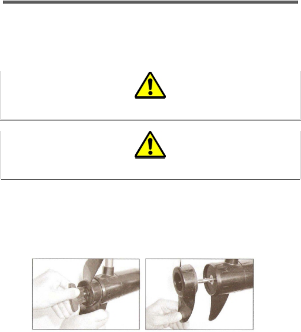
PROPELLER INSTALLATION
INCLUDED:
1. Three Bladed Propeller
2. Propeller Nut
3. Shear Pin
4. Propeller Nut Key
Always verify that the trolling motor power is disconnected before installing
or cleaning the propeller. Failure to do so may result in personal injury.
Never strike any part of the motor with a hammer. This may cause damage
to the motor armature, which is not covered by the warranty.
INSTALLING THE PROPELLER:
1. Slide the Three Bladed Propeller onto the motor’s shaft so that it rests
against the motor housing.
2. Install the Propeller Nut by threading it onto the motor’s shaft.
3. Tighten the Propeller nut using the Propeller Nut Key.
4. Install the Shear Pin in the hole near the end of the motor’s shaft.
RHODAN HDGPS ANCHOR+
Rhodan Marine Systems, Inc. 8274 Blaikie Ct. Sarasota, FL 34240 (941)706-4578
Page 21 of 26
APPENDIX B
SYSTEM CALIBRATION
For optimal system performance, it is recommended that these procedures
be conducted at least once after installation; however, the
HD
GPS ANCHOR
+
will perform adequately without these calibrations.
M
M
O
O
U
U
N
N
T
T
I
I
N
N
G
G
A
A
N
N
G
G
L
L
E
E
C
C
A
A
L
L
I
I
B
B
R
R
A
A
T
T
I
I
O
O
N
N
:
:
This calibration records the installed mounting angle of the unit.
1. Select the Manual Mode
2. Use the Left and Right Arrow buttons on the wireless fob to steer the
unit so that the thruster is aimed dead-ahead.
3. Simultaneously press both the Up and Down Arrow buttons.
The unit will emit (8) rapid “beeps” to indicate that it has updated the
system mounting angle and has returned to Manual Mode.
H
H
A
A
R
R
D
D
I
I
R
R
O
O
N
N
C
C
O
O
M
M
P
P
A
A
S
S
S
S
C
C
A
A
L
L
I
I
B
B
R
R
A
A
T
T
I
I
O
O
N
N
:
:
This calibrates the system for stray magnetic fields around the unit.
1. Select the Manual Mode
2. Use the directional arrows on the wireless fob to increase the speed
to a modest thrust level and steer to 90 degrees in either direction.
3. Simultaneously press the Left and Right Arrow buttons.
The unit will emit (8) rapid “beeps” to indicate that it has entered the
calibration
4. Steer the boat to make two complete circles.
5. Simultaneously press the Left and Right Arrow buttons.
The unit will emit (8) rapid “beeps” to indicate that it has compensated
for hard iron compass effects and has returned to Manual Mode.

RHODAN HDGPS ANCHOR+
Rhodan Marine Systems, Inc. 8274 Blaikie Ct. Sarasota, FL 34240 (941)706-4578
Page 22 of 26
MAINTENANCE AND STORAGE
It is recommended that the following steps be taken after each use.
Adhering to these recommendations can greatly increase the life of the unit.
Failure to properly maintain the unit may void the warranty and can result in
system damage, personal injury, and property damage.
¾Rinse off any salt water deposits and wipe the motor down with a
clean cloth soaked in warm water. Do not use a pressure washer to
clean the unit.
¾Check that the propeller is clear of any fishing line or weeds.
¾Use the prop nut tool to ensure the prop nut is properly secured.
¾Lubricate all moving parts with a non-aerosol lubricant.
¾Clean battery terminals regularly and check for loose terminal nuts.
¾Store in a well-ventilated, dry area
¾Do not leave the motor outside in the elements, especially in cold
winter and/or saltwater environments. Long exposure to sub-zero
temperature will reduce the strength of the permanent magnets of the
motor and result in reduced thrust.
¾Never use chemicals (alcohol, solvents, and acids) on any of the
system components.
¾Use a Vinyl UV protector periodically on the power cables to avoid
excessive sun damage.
¾Periodically check for loose connections and/or excessive corrosion.
RHODAN HDGPS ANCHOR+
Rhodan Marine Systems, Inc. 8274 Blaikie Ct. Sarasota, FL 34240 (941)706-4578
Page 23 of 26
REPLACING A WIRELESS REMOTE CONTROL FOB
Your HDGPS ANCHOR+was shipped with (2) fobs that are preprogrammed to
work exclusively with your unit. If you have lost both Fobs, you may order
replacements by contacting Rhodan Marine Systems. The following
procedure must be performed to program a new fob to your HDGPS ANCHOR+
TO PROGRAM A NEW WIRELESS FOB:
1) Power up the unit in the stowed position
2) Within 10 seconds, deploy the unit
3) Within 10 seconds, stow the unit
4) Within 10 seconds, deploy the unit once again
The unit will begin “beeping” indicating that it is ready to learn new
wireless fobs
5) Press any button on the new fob within 20 seconds
6) When the unit stops beeping, the new fob will be learned by your system
and is ready to be used.

RHODAN HDGPS ANCHOR+
Rhodan Marine Systems, Inc. 8274 Blaikie Ct. Sarasota, FL 34240 (941)706-4578
Page 24 of 26
TROUBLESHOOTING
PROBLEM POSSIBLE CAUSES AND/OR SOLUTIONS
Motor is shaking
¾Check for line or weed fouling of the
propeller.
¾Check Prop and Prop Nut
¾Check to see if propeller shaft is bent
¾The motor bearings or bushings may be
worn out.
Loss of Speed
¾Check battery condition. Recharge and
test for a bad cell.
¾Check battery connections for corrosion
¾The power wiring from the battery to the
motor may be too small. Use #6 AWG.
System does not respond
to wireless commands
¾Verify that unit is locked in the deployed
position
¾Cycle power off & back on
¾Replace battery in wireless fob
¾Follow Wireless Fob replacement
procedures
¾Contact Rhodan Customer Support
System will not Anchor
or Track
¾Allow at least 1-minute for system to
acquire a GPS fix. Listen for (4) beeps
indicating good GPS signal.
¾Make sure that nothing is blocking the sky
view of the GPS antenna
After selecting a mode,
system beeps twice and
then does nothing
¾Battery voltage is low
¾Check all connections
¾Recharge battery and test for a bad cell
Battery Drains
¾A small drain will be imposed on the
system batteries if powered-up when not
in use
¾Always unplug the system when not in use

RHODAN HDGPS ANCHOR+
Rhodan Marine Systems, Inc. 8274 Blaikie Ct. Sarasota, FL 34240 (941)706-4578
Page 25 of 26
RHODAN MARINE SYSTEMS
12 MONTH WARRANTY
Product Warranty
All
HD
GPS ANCHOR
+
Trolling motors produced by Rhodan Marine Systems
that have been under normal and proper usage are warranted to be free of
manufacturing defects for a period of one year after date of purchase.
CUSTOMER SERVICE
Have your unit serial number ready and call
1-800-RHODAN1 1-800-746-3261
We take pride in providing good service!
Rhodan Marine Systems
Sarasota Operations
8274 Blaikie Court
Sarasota, FL 34240
Ph. 941-706-4578
Fax 941-706-4579
RHODAN HDGPS ANCHOR+
Rhodan Marine Systems, Inc. 8274 Blaikie Ct. Sarasota, FL 34240 (941)706-4578
Page 26 of 26
OWNER’s NOTES:
____________________________________________________________________________________
____________________________________________________________________________________
____________________________________________________________________________________
____________________________________________________________________________________
____________________________________________________________________________________
____________________________________________________________________________________
____________________________________________________________________________________
____________________________________________________________________________________
____________________________________________________________________________________
____________________________________________________________________________________
____________________________________________________________________________________
____________________________________________________________________________________
____________________________________________________________________________________
____________________________________________________________________________________
____________________________________________________________________________________
____________________________________________________________________________________
____________________________________________________________________________________
____________________________________________________________________________________
____________________________________________________________________________________
____________________________________________________________________________________
____________________________________________________________________________________