Rhodan Marine Systems RMS-FOB1 Anchor Fob 1 User Manual
Rhodan Marine Systems, Inc. Anchor Fob 1 Users Manual
UserManual.wiki
>
Rhodan Marine Systems
>
RMS FOB1 User Manual
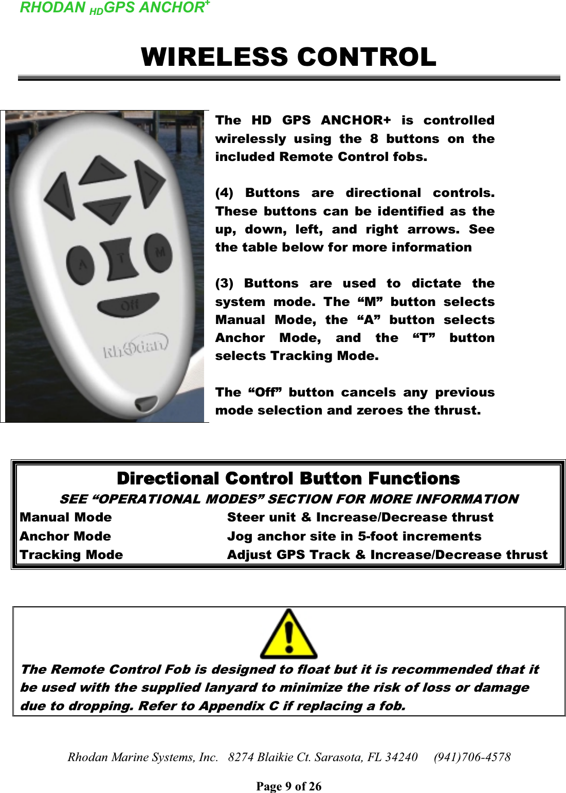
Users Manual
Navigation menu
Upload a User Manual
Namespaces
Wiki Guide
HTML
PDF
Info
Views
User Manual
Discussion / Help
Navigation