Ricoh 7080A Compact Disk Rewritable Drive User Manual
Ricoh Company Ltd Compact Disk Rewritable Drive Users Manual
Ricoh >
Users Manual
COMPACT DISC REWRITABLE DRIVE
MP7080A
SPECIFICATIONS
(Preliminary)
RICOH Company, Ltd.
Oct. 10, 1999
DRC – 60x - 2xx

NOTICE
This equipment has been tested and found to comply with the limits for a Class B digital
device , pursuant to part 15 of the FCC Rules. These limits are designed to provide
reasonable protection against harmful interference in a residential installation. This
equipment generates , uses and can radiate radio frequency energy and , if not installed
and used in accordance with the instructions , may cause harmful interference to radio
communication.
However , there is no guarantee that interference will not occur in a particular installation.
If this equipment does cause harmful interference to radio or television reception , which
can be determined by turning the equipment off and on , the user is encouraged to try to
correct the interference by one or more of the following measures :
---Reorient or relocate the receiving antenna.
---Increase the separation between the equipment and receiver.
---Connect the equipment into an outlet on a circuit different from that to which the
receiver is connected.
---Consult the dealer or an experienced radio / TV technician for help.
FCC WARNING
Changes or modification not expressly approved by the party responsible for compliance
could void the user's authority to operate the equipment.
CAUTION
Use of controls or adjustments or performance of procedures other than those specified
herein may result in hazardous radiation exposure.
a) Pay careful attention not to let the invisible laser beam emitted from the optical pickup
enter into your eyes.
b) When you find a troubled state of the component in the optical pickup containing the
laser diode , change to the specified new optical pickup. Do not open the optical pickup
housings.

Akustischer Geräuschpegel
Dieser Drucker überschreitet einen Geräuschpegel von 70 dB (A) während dem Betrieb
nicht.
Declaration of Conformity
“The Product complies with the requirements of the EMC Directive 89/336/EEC
and the Low Voltage Directive 73/23/EEC.”

Revision History
No. Revised Data Revision Contents Description Page
Oct. 10, 1999 Preliminary

CONTENTS
I. OUTLINE-------------------------------------------------------------------------------------------------
1. Overview...................................................................................................... I - 1
2. Features....................................................................................................... I - 1
II. CONSTRUCTION AND INSTALLATION ------------------------------------------------------
1. Basic Construction and Connectors.............................................................. II - 1
III. SPECIFICATIONS-----------------------------------------------------------------------------------
1. Functionality............................................................................................... III - 1
2. Basic Specification ..................................................................................... III - 2
3. Audio Specification..................................................................................... III - 3
4. Performance Specification.......................................................................... III - 3
5. Condition for use and Safety standard........................................................ III - 3
6. Reliability and Usable Life .......................................................................... III - 6
7. Safety Standards........................................................................................ III - 6
8. Appearance................................................................................................ III - 7
9. Storage Conditions..................................................................................... III - 8
10. Emergency Eject ........................................................................................ III - 10
11. Disc............................................................................................................ III - 11
12. Packet Command....................................................................................... III - 12

FIGURE
II - 1. Front.................................................................................................... II - 1
II - 2. Back.................................................................................................... II - 1
II - 3. Device Configuration Jumper .............................................................. II - 2
III - 1. Installation Conditions ......................................................................... III - 5
III - 2. CD-R/RW Drive Dimension ................................................................. III - 7
III - 3. Packing Arrangement.......................................................................... III - 9
III - 4. Emergency Eject ................................................................................. III - 10
TABLE
III - 1. Packet Command................................................................................ II - 1
I. OUTLINE
1. Overview
The Multimedia Printer Series Drive (the CD-R/RW Drive) can do much more than read
and write the usual CD-R discs. When you load it with a rewritable CD-RW disc, you
can record, read, and edit any kind of data, because these discs allow you to rewrite
information that has already been recorded.
2. Features
1) Running OPC*1 gives a flatter writing signal that improves reliability.
2) An improved anti-heat design means that no cooling fan is needed.
3) Easy-to-use tray model.
4) Uses the world standard ATAPI interface.
5) Can read not only CD-R and CD-RW discs, but also video CDs, music CDs, and
photo CDs.
6) Can read data at 32x speed and write data at 8x speed on CD-R, 4x speed on
CD-RW discs.
7) The recorded CD-RW media can be played in a DVD player or multimedia CD-
ROM player, maintaining future compatibility.
8) Supports packet write for easy writing to CD-R and CD-RW discs.
*1 Continuously monitors the signal level during recording and adjusts the laser
power to compensate when the disc is dirty, insuring a flat signal.
II. CONSTRUCTION AND INSTALLATION
1. Basic construction and Connectors
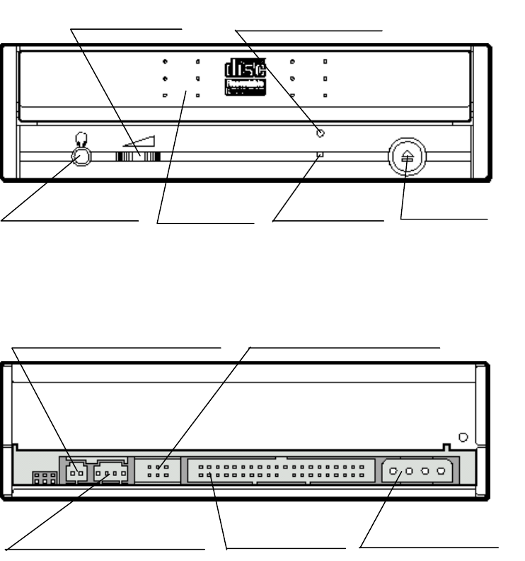
The Connectors are located as shown below. The function of each parts are also
described below.
Fig. II - 1 Front
Fig. II - 2 Back
Volume control
Eject Button
Headphone Jack Disc Tray Busy indicator
Emergency Eject hole
Digital Audio Output (Not used) Device Configuration Jumper
Audio Output Connector E-IDE Connector Power Connector
1.1. Disc Tray
This is the tray for the disc. Place the disc on the ejected disc tray, then lightly
push the tray (or push the eject button) and the CD will be loaded.
! - Don’t use force to pull out or push in the disc tray. This might cause damage
to the loading section of the drive.
1.2. Eject Button
This is the button used to eject or bring in the disc tray.
1.3. Busy indicator
When the disc tray or disc is being accessed, the light shines or flashes orange.
Even when a disc is loaded or a disc is not being accessed, the light go out. When a
illegal disc is loaded or some hardware trouble occurs, the indicator blinks.
1.4. Headphone Jack
This jack is for connecting headphones or mini-speakers.
1.5. Volume control
This is used to adjust the output volume of the headphone jack. It can’t be used to
adjust the output volume for the audio output connectors on the rear panel.
1.6. Emergency Eject hole
When the drive can not eject the Disc Tray because of power failure, pushing the
Emergency Eject hole of the Front Panel by the thin pole make drive be able to
eject the Disc Tray.
! - This function is only for emergency case. Do not use this function in usual
case to prevent from mechanical damage.
1.7. Power Connector
Used to connect to the host computer’s power supply (DC 5V / 12V)
! - Be careful not to reverse the poser connector when attaching it. A reversed
connection may cause damage to the equipment (not covered by the
warranty).
1.8. E-IDE Connector
Use a 40 pin double-end flat E-IDE cable to connect to the E-IDE interface.
! - Connecting or disconnecting connectors while power is on may result in a
short circuit, causing damage to the equipment. When connecting or
disconnecting connectors, make sure to turn off the power beforehand.
1.9. Audio Output Connector
Used to connect to the sound card. (Analog signal.)
1.10. Digital Audio Output (Not used)
Used to connect to the sound card. (Digital signal.) It is not used with this drive.
1.11.Device Configuration Jumper
Used when selecting the Device Configuration of E-IDE. Don’t use jumpers to
change anything besides the Device Configuration, but keep the drive as initially
set(“Master” position). Configuration changes become valid after power is turned off,
then on again.
! - Installing jumper pins besides the ones for Device Configuration settings may
be the cause of damage or abnormal drive operation.
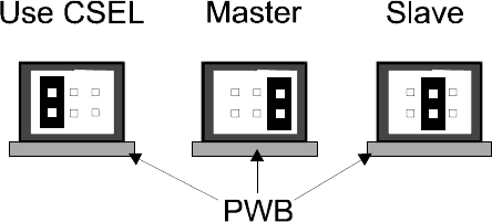
Fig. II - 3 Device Configuration Jumper
The Device Configuration Jumper will be set to Master as factory setting.