Ricoh RFAPL03 Color Copier User Manual Connecting to the Interface Short Confidential
Ricoh Company Ltd Color Copier Connecting to the Interface Short Confidential
Ricoh >
Contents
- 1. User Manual(Connecting to the Interface) (Short Confidential)
- 2. User Manual(Seting Telephone HandSet) (Short Confidential)
- 3. User Manual(Setting Fax Interface) (Short Confidential)
- 4. User Manual_1 (Short Confidential)
- 5. User Manual_2 (Short Confidential)
User Manual(Connecting to the Interface) (Short Confidential)
2. Connecting the Machine
This chapter describes how to connect the machine to the network and specify the network settings.
Connecting to the Interface
This section explains how to identify the machine's interface and connect the machine according to the
network environment.
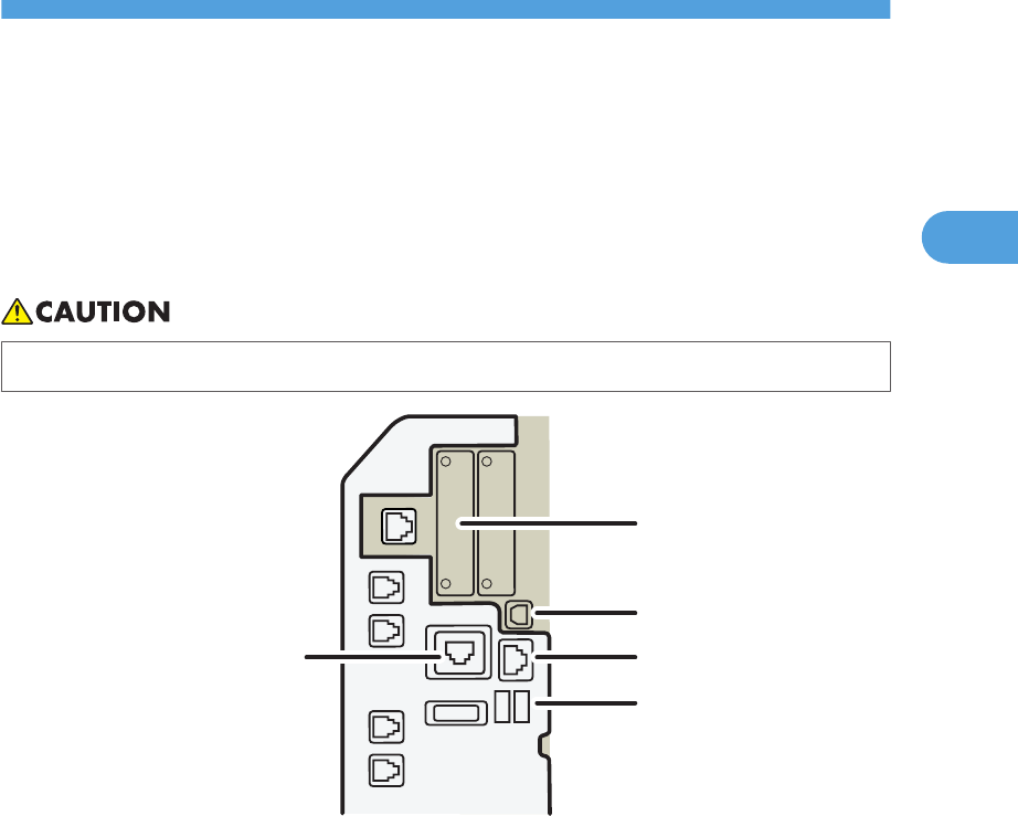
• A network interface cable with a ferrite core must be used for RF interference suppression.
BZU006
1
2
3
4
5
1. Slot A
Install an optional interface board in this slot.
The slot can accommodate one of the following interface boards:
• IEEE1284 interface board: Required if you want to connect an IEEE 1284 cable to this machine. When
installed in Slot A, this board allows you to connect the machine to a computer through an IEEE 1284
cable.
• Wireless LAN interface unit: Required if you want to connect this machine to a wireless LAN. When installed
in Slot A, this unit allows you to connect the machine to an IEEE 802.11 a or IEEE 802.11 b/g wireless
LAN.
• Bluetooth interface unit: Required if you want to give the machine Bluetooth capability. When installed in
Slot A, this unit allows the machine to communicate via Bluetooth with an external device.
2. USB 2.0 [Type B] port
Port for connecting the USB2.0 [Type B] interface cable
3. 10BASE-T/100BASE-TX port
Port for connecting the 10BASE-T or 100BASE-TX cable
75
2
4. USB Host Interface
Port for connecting the USB interface cable
Use this interface to connect the machine to a card authentication device or memory card reader.
5. Gigabit Ethernet port (optional)
Port for using the 1000BASE-T, 100BASE-TX, or 10BASE-T cable
• Slot A can contain one module only: You can install only one IEEE 1284 interface board, one Wireless
LAN interface unit, or one Bluetooth interface unit at a time in this slot.
• The Ethernet and Gigabit Ethernet port cannot be used simultaneously. If the optional Gigabit Ethernet
board is installed, connect the Ethernet cable to the port on the Gigabit Ethernet board Communication
with the machine will fail if cables are connected to both ports simultaneously.
Connecting to the Ethernet Interface
This section describes how to connect an Ethernet cable to the Ethernet interface.
• If the main power switch is on, turn it off.
• Use the following Ethernet cables.
• Unshielded Twisted Pair Cable (UTP) or Shielded Twisted Pair Cable (STP) and Category type
5 or more
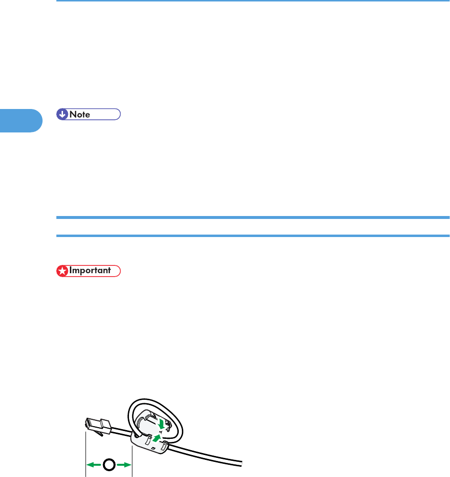
1. Make a loop 5 cm (2.1 inch) (1) from the end of the Ethernet cable and attach the included
ferrite core to the loops as shown.
1
BZU007
2. Make sure the main power is switched off.
2. Connecting the Machine
76
2
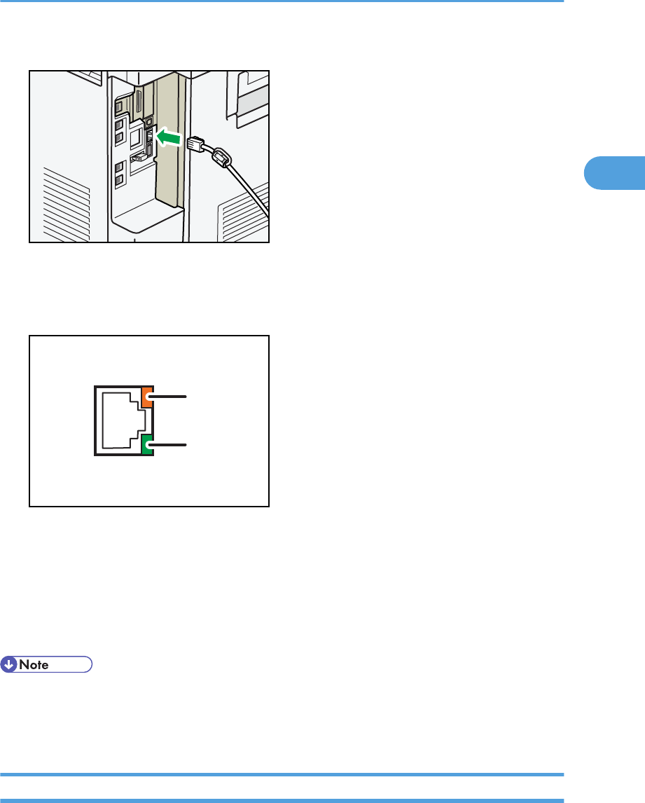
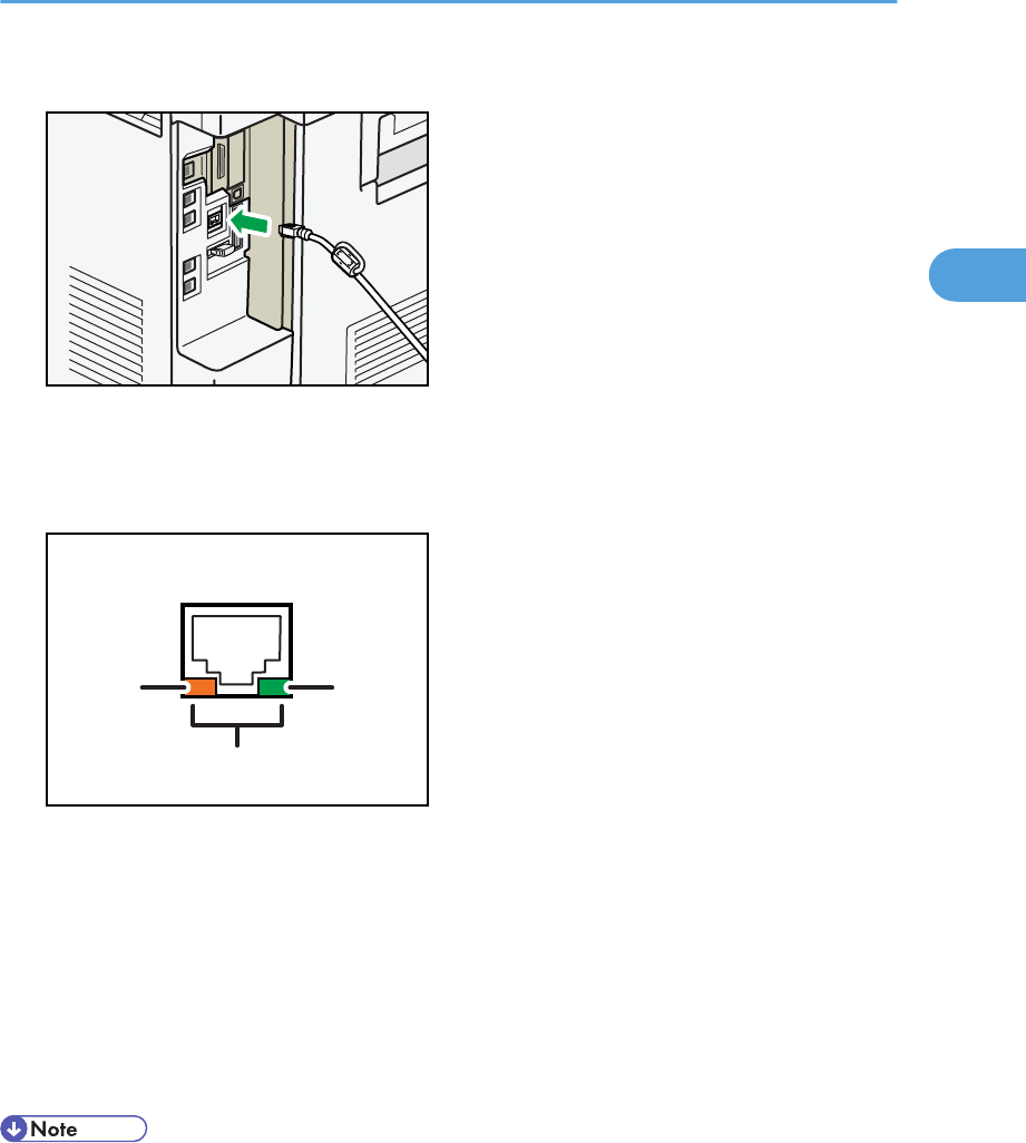
3. Connect the Ethernet interface cable to the 10BASE-T/100BASE-TX port.
BZU008
4. Connect the other end of the Ethernet interface cable to a network connection device such
as a hub.
5. Turn on the main power switch of the machine.
BZU009
1
2
1. Indicator (orange)
When 100BASE-TX is operating, the LED is lit orange. When 10BASE-T is operating or the machine is not
connected to the network, it is turned off.
2. Indicator (green)
When 10BASE-T is operating, the LED is lit green. When 100BASE-TX is operating or the machine is not
connected to the network, it is turned off.
• For details about how to turn on the main power switch, see "Turning On the Power", About This
Machine.
• For details about installing the printer driver, see "Preparing the Machine", Printer Reference.
Connecting to the Gigabit Ethernet Interface
This section describes how to connect the Ethernet interface cable to the Gigabit Ethernet port.
Connecting to the Interface
77
2
• If the main power switch is on, turn it off.
• Use the following Ethernet cables.
• When using 100BASE-TX/10BASE-T:
Unshielded Twisted Pair Cable (UTP) or Shielded Twisted Pair Cable (STP) and Category type
5 or more
• When using 1000BASE-T:
Unshielded Twisted Pair Cable (UTP) or Shielded Twisted Pair Cable (STP) and Category type
5e or more
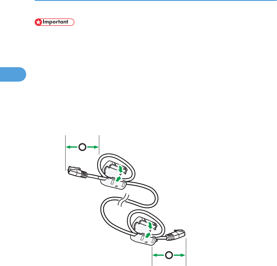
1. Make loops 5 cm (2.1 inch) (1) from the end of each Ethernet cable and attach included
ferrite cores to each loop as shown.
1
1
BZU010
2. Make sure the main power is switched off.
2. Connecting the Machine
78
2
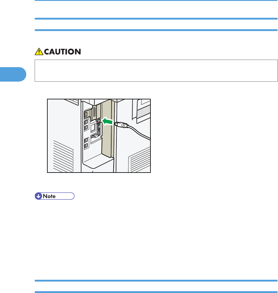
3. Connect the Ethernet interface cable to the Gigabit Ethernet port.
BZU011
4. Connect the other end of the Ethernet interface cable to a network connection device such
as a hub.
5. Turn on the main power switch of the machine.
BZU012
3
2
1
1. Indicator (orange)
When 100BASE-T is operating, the LED is lit orange. When 10BASE-TX is operating or the machine is not
connected to the network, it is turned off.
2. Indicator (green)
When 10BASE-TX is operating, the LED is lit green. When 100BASE-T is operating or the machine is not
connected to the network, it is turned off.
3. Indicators (both orange and green)
When 1000BASE-T is operating, both LED are lit.
• For details about how to turn on the main power switch, see "Turning On the Power", About This
Machine.
• For details about installing the printer driver, see "Preparing the Machine", Printer Reference.
Connecting to the Interface
79
2
Connecting to the USB (Type B) Interface
This section describes how to connect the USB2.0 (Type B) interface cable to the USB2.0 port.
• Properly shielded and grounded cables and connectors must be used for connections to a host
computer (and/or peripheral) in order to meet emission limits.
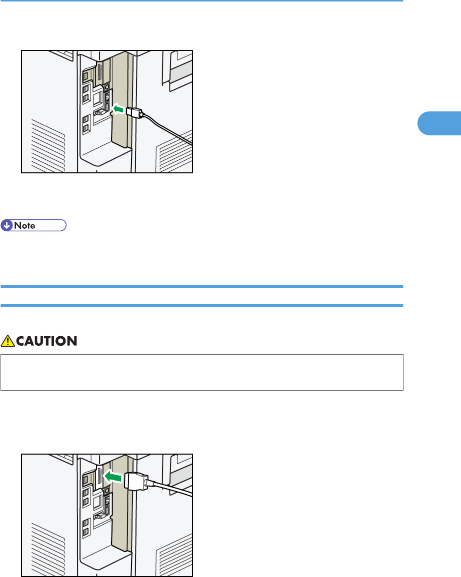
1. Connect the USB2.0 (Type B) interface cable to the USB2.0 port.
BZU013
2. Connect the other end to the USB2.0 port on the host computer.
• This machine does not come with a USB interface cable. Make sure you purchase the appropriate
cable for the machine and your computer.
• The USB2.0 interface board is supported by Windows 2000/XP/Vista/7, Windows Server
2003/2003 R2/2008/2008 R2, Mac OS X 10.3.3 or higher.
• To use Macintosh, the machine must be equipped with the optional PostScript 3 unit. When used
with Mac OS X 10.3.3 or higher, a transfer speed of USB2.0 is supported.
• For details about installing the printer driver, see "Preparing the Machine", Printer Reference.
Connecting a Device to the Machine's USB Host Interface
This section explains how to connect a device to the machine's USB host interface.
2. Connecting the Machine
80
2
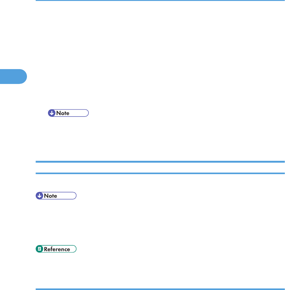
1. Connect one end of the USB interface cable to the machine's USB host interface.
BZU021
2. Connect the other end of the USB interface cable to a card authentication device or media
slot.
• This machine does not come with a USB interface cable. Make sure you purchase the appropriate
cable.
Connecting to the IEEE 1284 Interface
This section describes how to connect the IEEE 1284 interface cable to the IEEE 1284 interface board.
• Properly shielded and grounded cables and connectors must be used for connections to a host
computer (and/or peripheral) in order to meet emission limits.
1. Make sure the main power switch on the machine is off.
2. Turn off the main power switch of the host computer.
3. Connect the IEEE 1284 interface cable to the IEEE 1284 port.
BZU014
Connecting to the Interface
81
2
You might have to use a conversion adapter to connect the cable to the interface. For details about
acquiring a conversion adapter, consult your sales or service representative.
4. Connect the other end of the cable into the interface connector on the host computer.
Check the shape of the connector to the computer. Connect the cable firmly.
5. Turn on the main power switch of the machine.
6. Turn on the host computer.
When using Windows 2000/XP/Vista/7, and Windows Server 2003/2003 R2/2008/2008 R2,
a printer driver installation screen might appear when the computer is turned on. If this happens, click
[Cancel] on the screen.
• For details about how to turn on the main power switch, see "Turning On the Power", About This
Machine.
• For details about installing the printer driver, see "Preparing the Machine", Printer Reference.
Connecting to the Wireless LAN Interface
This section describes how to connect to the wireless LAN interface.
• Check the machine's IPv4 address and subnet mask, or the IPv6 address settings.
• For details about how to set the IPv4 address and subnet mask from the control panel of the machine,
see "Interface Settings".
• Before using this machine with a wireless LAN interface, you must select [Wireless LAN] in [LAN Type].
• p.38 "Interface Settings"
Setup Procedure
This section describes how to setup wireless LAN interface.
To configure the wireless LAN settings: open [System Settings], [Interface Settings], select [Wireless LAN],
and then use the following procedure.
2. Connecting the Machine
82
2