Ridgid Dp15501 Users Manual
DP15501 to the manual ad58cc88-c74f-4ceb-b81a-7fb945ab6bfd
2015-02-04
: Ridgid Ridgid-Dp15501-Users-Manual-387752 ridgid-dp15501-users-manual-387752 ridgid pdf
Open the PDF directly: View PDF ![]() .
.
Page Count: 40
- WARNING: To reduce the risk of injury, the user must read and understand the operator's manual before using this product.
- Table of Contents
- Safety Instructions For Drill Press
- Safety Instructions For Drill Press (continued)
- Safety Instructions For Drill Press (continued)
- Plan Ahead To Protect Your Eyes, Hands, Face and Ears
- Glossary of Terms
- Motor Specifications and Electrical Requirements
- Motor Specifications and Electrical Requirements
- (continued)
- 110-120 Volt, 60 Hz. Tool Information
- Motor Safety Protection
- 1. Connect this tool to a power source with the appropriate voltage for your model and a 15-amp branch circuit with a 15-amp time delay fuse or circuit breaker. Using the wrong size fuse can damage the motor.
- 2. If the motor won't start, turn the switch off immediately and unplug the tool. Check the quill to make sure it turns freely. ...
- 3. Fuses may "blow" or circuit breakers may trip frequently if:
- a. Motor Is Overloaded - Overloading can occur if you feed too rapidly or make too many start/stops in a short time.
- b. Line voltages should not be more than 10% above or below the nameplate voltage. For heavy loads, however, the voltage at motor terminals must equal the voltage specified for your model.
- c. Improper or dull drill bit is used.
- 4. Most motor troubles may be traced to loose or incorrect connections, overload, low voltage (such as small size wire in the su...
- Wire Sizes
- Unpacking and Checking Contents
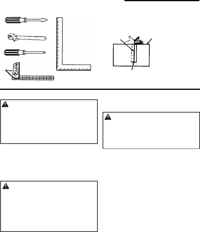
- Tools Needed
- Unpacking
- 1. Separate all “loose parts” from packing materials and check each item with illustration and “Table of Loose Parts.”
- 2. Remove the protective oil that is applied to the table and column. Use any ordinary household type grease and spot remover.
- 3. Apply a coat of paste wax to the table and column to prevent rust. Wipe all parts thoroughly with a clean dry cloth.
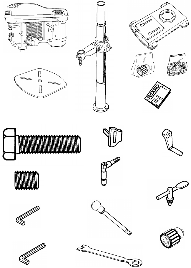
- List of Loose Parts
- Item Description Qty.
- Loose Parts
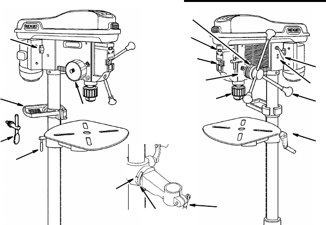
- Location and Function of Controls
- 1. Belt Tension Handle...Turn handle counterclockwise to apply tension to belt, turn handle clockwise to release belt tension.
- 2. Head Lock Set Screws...Locks the head to the column. Always have them locked in place while operating the drill press.
- 3. Feed Handle...For moving the chuck up or down. One or two of the handles may be removed if necessary whenever the workpiece is of such unusual shape that it interferes with the handles.
- 4. Table Crank...Turn clockwise to elevate table. Support lock must be released before operating crank.
- 5. Chuck...Holds drill bit or other recommended accessory to perform desired operations.
- 6. Depth Scale...Allows operator to adjust drill press to drill to a desired depth.
- 7. Drill “On-Off” Switch...Has locking feature to prevent unauthorized and possible hazardous use by children and others.
- 8. Light “On-Off” Switch...Turns the light on and off.
- 9. Depth Scale Lock...Locks the depth scale at selected depth.
- 10. Spring Cap...Provides means to adjust quill spring tension.
- 11. Table Lock...Allows table to be rotated in various positions and locked.
- 12. Table Bevel Lock...Locks the table in any position from 0˚- 45˚.
- 13. Bevel Scale...Shows degree table is tilted for bevel operations. Scale is mounted on side of arm.
- 14. Support Lock Handle...Tightening locks table support to column. Always have it locked in place while operating the drill press.
- 15. Chuck Key...Used to tighten drill in the chuck and also to loosen the chuck for drill removal.
- 16. Storage Tray...Conveniently holds drill bits and other accessories.
- 17. Belt Tension Lock Handles...Tightening handles locks motor bracket support to maintain correct belt distance and tension.
- Assembly
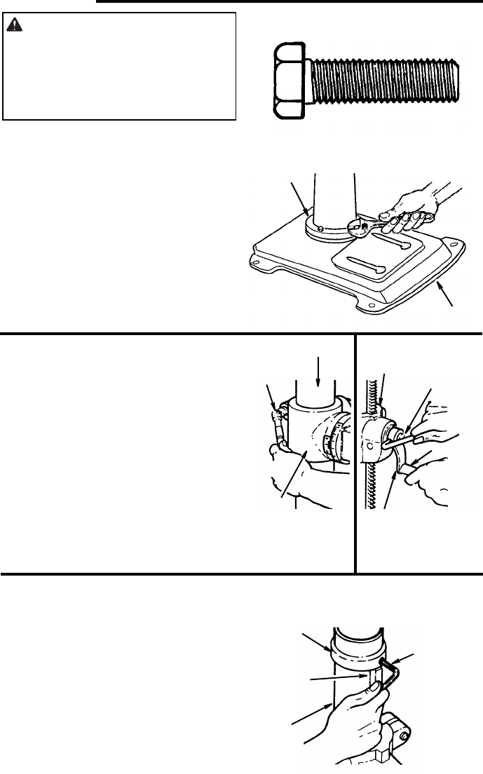
- Assembly of Base/Column
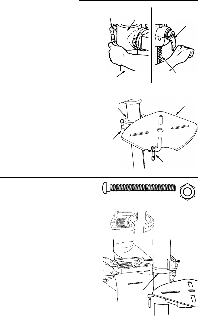
- 1. Locate four (4) 10mm dia. x 40mm long bolts among loose parts bag.
- 2. Position base on floor. Remove protective covering and discard.
- 3. Remove protective sleeve from column tube and discard. Place column assembly on base, and align holes in column support with holes in base.
- 4. Install a bolt in each hole through column support and base and tighten with adjustable wrench.
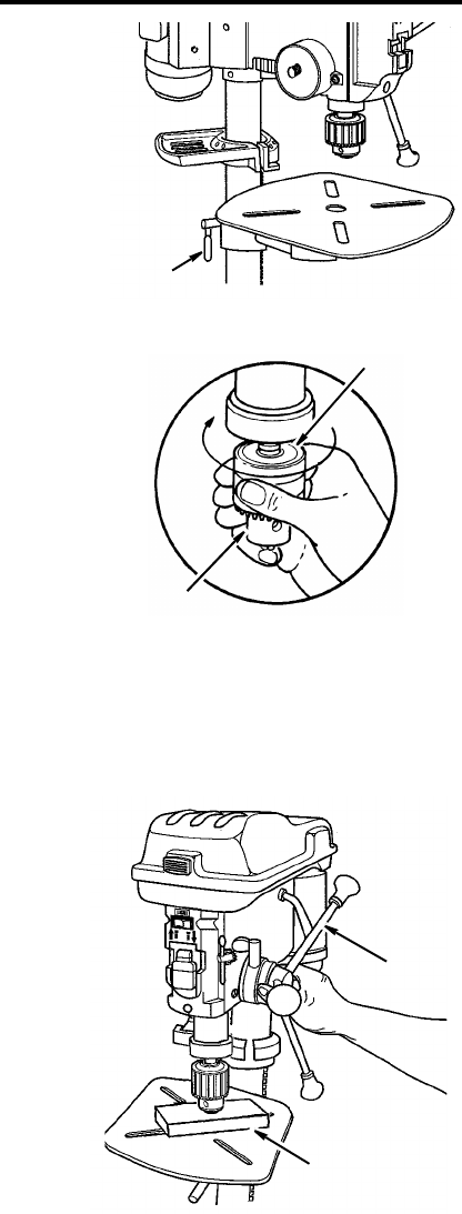
- 5. Locate table crank and support lock from loose parts.
- 6. Install support lock from left side into table support and tighten by hand.
- 7. Install table crank assembly and tighten set screw with a 3mm hex “L” wrench. Do not overtighten. Set screw should be tightened against the flat section of the shaft.
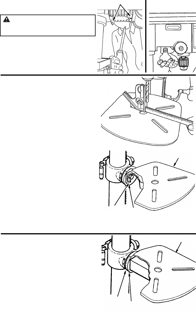
- 8. Check column collar for proper adjustment. Collar should not be angled on the column and it should be positioned so rack will...
- Assembly of Base/Column
- Assembly (continued)
- Installing The Table
- 1. Loosen support lock and raise table support by turning table crank clockwise until support is at a working height level. Tighten support lock.
- 2. Remove protective covering from table and discard. Loosen table lock, place table in table support and tighten table lock (located under table) by hand.
- Installing the Storage Tray
- Installing the Head
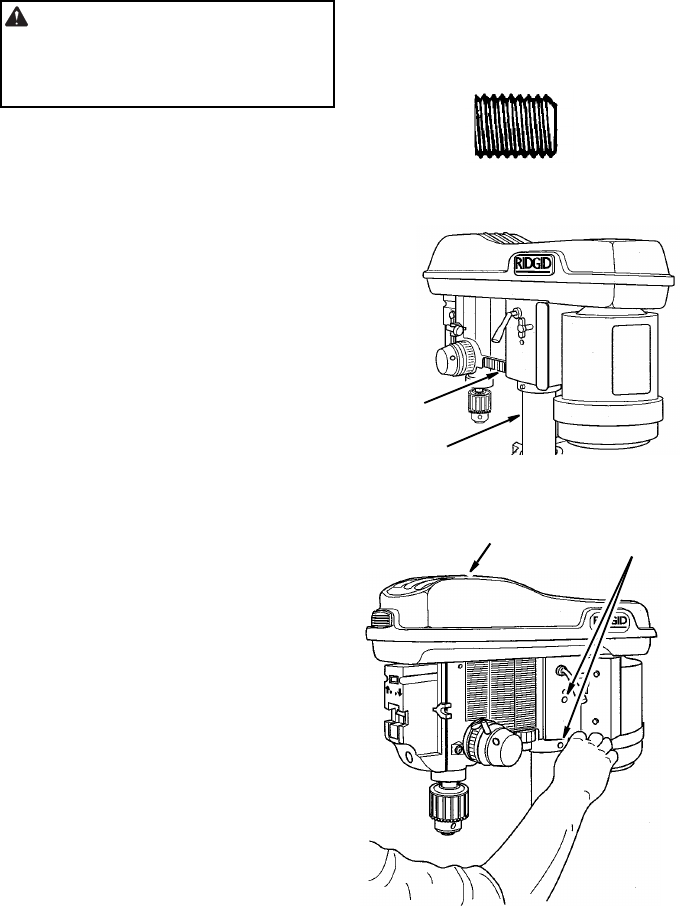
- 1. Locate (2) two 10mm dia. x 12mm long set screws in loose parts bag.
- 2. Remove protective bag from head assembly and discard. Carefully lift head above column tube and slide it onto column making sure head slides down over column as far as possible. Align head with table and base.
- 3. Install a set screw in each hole (as indicated) on the right side of the head, and using a 5mm hex “L” wrench, tighten the two head lock set screws.
- Installing The Table
- Assembly (continued)
- Pulley Alignment and Speed Adjustment
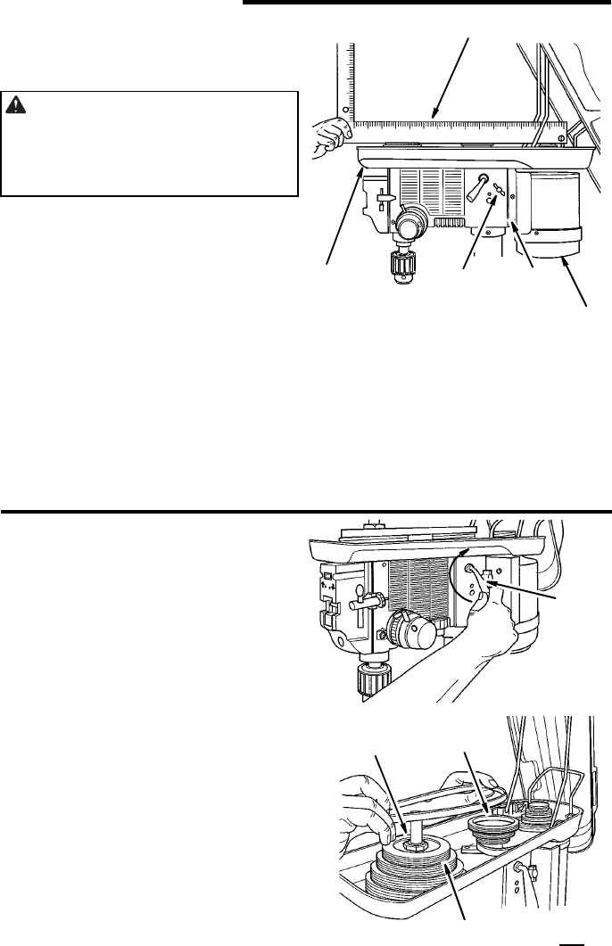
- 1. Place the idler pulley from loose parts bag into the head as shown. Place belts from loose parts bag on pulleys following speed adjustment instructions below.
- 2. Place a straightedge such as a piece of wood, metal, or framing square across the top of pulleys.
- 3. The top of all three pulleys should touch the straightedge.
- 4. If not:
- 2. Loosen belt tension by turning belt tension handle clockwise.
- 3. Use speed chart inside belt guard to choose speed for drilling operation. Install belts in correct position for desired speed. The longer of the two belts is always positioned between the spindle pulley and idler pulley.
- Tensioning Belt
- 1. Apply tension to belt by turning belt tension handle counterclockwise until belt deflects approximately 1/2 inch by thumb pressure at its center.
- 2. Tighten belt tension lock handles.
- 3. If belt slips while drilling, readjust belt tension. Also make sure the ribs in the belt are aligned with grooves in the pulley.
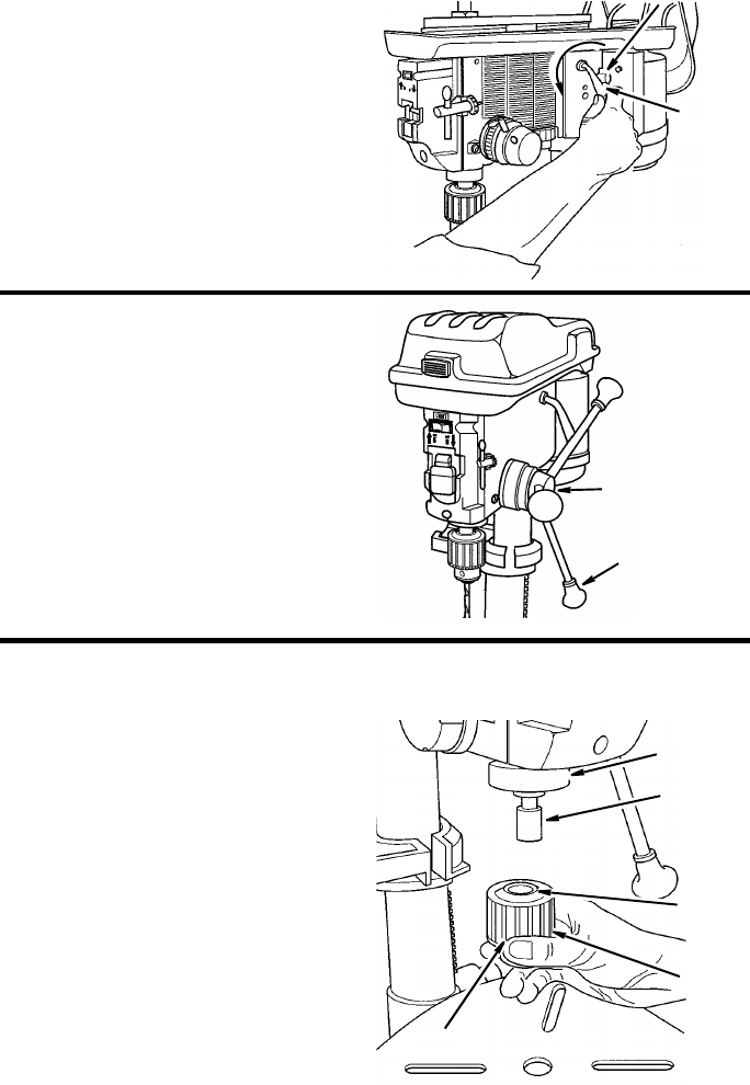
- Installing Feed Handles
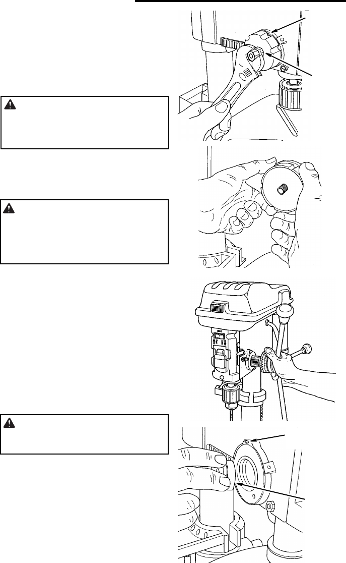
- Installing the Drill Chuck
- Pulley Alignment and Speed Adjustment
- Assembly (continued)
- 4. Unlock support lock and raise table so its about two (2) inches below tip of chuck.
- 5. Turn chuck sleeve clockwise and open jaws in chuck completely.
- 6. Place a piece of wood on table. Turn feed handles counterclockwise and force chuck against table until chuck is secure.
- Installing Light Bulb
- Adjusting the Table Square To Head
- 1. Insert precision round steel rod or straight drill bit approximately 3” long into chuck and tighten.
- 2. With table raised to working height and locked on column, place combination square flat on table beside rod or bit.
- 3. If an adjustment is necessary, loosen the set screw under bevel lock with 3mm “L” wrench, then loosen the table bevel lock bolt with the 24mm hex box wrench (included). (This adjustment is located under the table).
- 4. Align the table square to the rotor bit by rotating table until the square and rod or bit are in line.
- 5. Retighten table bevel lock.
- 6. Retighten set screw.
- Bevel Scale
- dp1550_6490b15dpEhalf_ENG.pdf
- Assembly (continued)
- Assembly (continued)
- Getting To Know Your Drill Press
- Getting To Know Your Drill Press (continued)
- Getting To Know Your Drill Press (continued)
- Safety Instructions for Basic Drill Press Operation
- Getting To Know Your Drill Press (continued)
- Basic Drill Press Operation
- Basic Drill Press Operation (continued)
- Maintenance
- Wiring Diagram
- Troubleshooting
- Repair Parts
- Repair Parts
- Repair Parts
- Repair Parts
- Repair Parts

SAVE THIS MANUAL FOR
FUTURE REFERENCE
,1&+)/225
02'(/'5,//35(66
Part No. SP6490 Printed in China
'3
23(5$725·60$18$/
WARNING: To reduce the risk of
injury, the user must read and under-
stand the operator’s manual before
using this product.

2
Table of Contents
Section Page
Table of Contents .......................................... 2
Safety Instructions For Drill Press ................. 2
Safety Symbols .......................................... 2
Before Using The Drill Press ..................... 3
When Installing Or Moving The Drill Press .... 3
Before Each Use ........................................... 4
Use Only Accessories Designed For This Drill
Press To Reduce The Risk of Serious Injury
From Thrown Broken Parts Or Work Pieces . 4
Plan Ahead To Protect Your Eyes, Hands, Face
and Ears ........................................................ 6
Glossary of Terms ......................................... 7
Motor Specifications and Electrical
Requirements ........................................... 7
110-120 Volt, 60 Hz. Tool Information ........ 8
Motor Safety Protection .............................. 9
Unpacking and Checking Contents ............. 10
Tools Needed ........................................... 10
Unpacking ................................................. 10
List of Loose Parts .................................... 11
Loose Parts in Box and Bag ..................... 11
Location and Function of Controls ............... 12
Assembly ..................................................... 13
Assembly of Base/Column ........................ 13
Installing The Table .................................. 14
Installing the Storage Tray ........................ 14
Installing the Head .................................... 15
Pulley Alignment and Speed Adjustment .. 16
Tensioning Belt ......................................... 17
Installing Feed Handles ............................ 17
Installing the Drill Chuck ........................... 17
Installing Light Bulb ................................... 19
Section Page
Adjusting the Table Square To Head ........ 19
Bevel Scale ...............................................19
Converting From Right Hand Operation to Left
Hand Operation ...................................... 20
Quill Return Spring ................................... 22
Adjusting Belt Latch Guard ........................ 23
Getting To Know Your Drill Press ................ 24
Spindle Speed in R.P.M. ........................... 25
Drilling to a Specific Depth ........................ 27
Another Way - Depth Scale ...................... 27
Locking Chuck at Desired Depth .............. 28
Removing Chuck and Arbor ...................... 28
Safety Instructions for Basic Drill Press
Operation ................................................ 29
Plan Ahead To Protect Your Eyes, Hands, Face
and Ears ...................................................... 29
Use Only Accessories Designed For This Drill
Press To Reduce the Risk of Serious Injury
From Thrown Broken Parts Or Work Pieces 30
Basic Drill Press Operation ......................... 30
Installing Drills ........................................... 30
Positioning Table and Workpiece ............. 31
Tilting Table .............................................. 32
Hole Location ............................................ 32
Feeding ..................................................... 32
Maintenance ................................................ 33
Lubrication ................................................ 33
Wiring Diagram ............................................ 33
Troubleshooting ........................................... 33
Repair Parts ................................................ 35
Safety Instructions For Drill Press
Safety Symbols
DANGER: indicates an imminently
hazardous situation which, if not
avoided, will result in death or serious
injury.
WARNING: indicates a potentially
hazardous situation which, if not
avoided, could result in death or seri-
ous injury.
CAUTION: indicates a potentially
hazardous situation which, if not
avoided, may result in minor or mod-
erate injury. It may also be used to
alert against unsafe practices that
may cause property damage.
NOTE: Advises you of information or
instructions vital to the operation or
maintenance of the equipment.
Do not attempt to use the tool until you have read thoroughly and understand
completely the operator’s manual. Pay close attention to the safety rules, in-
cluding Dangers, Warnings, and Cautions. If you use this tool properly and
only for what it is intended, you will enjoy years of safe, reliable service.
WARNING:
3
Before Using The Drill Press
WARNING: Some dust created
by power sanding, sawing, grinding,
drilling, and other construction
activities contains chemicals known
(to the State of California) to cause
cancer, birth defects or other repro-
ductive harm. Some examples of
these chemicals are:
• Lead from lead-bases paints,
• Crystalline silica from bricks and
cement and other masonry prod-
ucts, and
• Arsenic and chromium from
chemically-treated lumber.
Your risk from these exposures var-
ies, depending on how often you do
this type of work. To reduce your
exposure to these chemicals: work
in a well ventilated area, and work
with approved safety equipment,
such as those dust masks that are
specially designed to filter out
microscopic particles.
WARNING: To reduce the risk
of mistakes that could cause seri-
ous, permanent injury, do not plug
the drill press in until the following
steps have been satisfactorily com-
pleted.
• Completely assemble and align drill
press (See “Assembly” section).
• Learn the use and function of the
ON-OFF switch. (See “Getting to
Know Your Drill Press” section).
• Review and understand all safety
instructions and operating proce-
dures in this manual.
• Review the maintenance methods
for this drill press (See “Mainte-
nance” section).
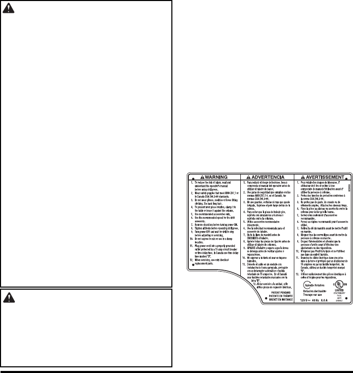
• Find and read all the warning labels
found on the drill press (shown
below).
When Installing Or Moving The Drill Press
Reduce the Risk of Dangerous
Environment.
• Use the drill press in a dry, indoor
place protected from rain.
• Keep work area well lighted.
• Use recommended accessories.
The use of improper accessories
may cause risk of injury to persons.
To reduce the risk of injury from
unexpected drill press movement.
If there is any tendency of the drill
press to tilt or move during any use,
bolt it to the floor. Make sure and
leave adequate room to fully open the
belt guard. If the workpiece is too
large to easily support with one hand,
provide an auxiliary support.
• To reduce the risk of injury from
electrical shock, make sure your fin-
gers do not touch the plug’s metal
prongs when plugging in or unplug-
ging the drill press.

4
Safety Instructions For Drill Press (continued)
•Never Stand On Tool. Serious
injury could occur if the tool tips or
you accidentally hit the cutting tool.
Do not store anything above or near
the tool where anyone might stand
on the tool to reach them.
Before Each Use
Inspect your drill press.
• To reduce the risk of injury from
accidental starting, turn the switch
off, unplug the drill press, and
remove the switch key before rais-
ing the guard, changing the cutting
tool, changing the setup, or adjust-
ing anything. Make sure switch is in
OFF position before plugging in.
• Check for alignment of moving
parts, binding of moving parts,
breakage of parts, drill press stabil-
ity, and any other conditions that
may affect the way the drill press
works.
• If any part is missing, bent or broken
in any way, or any electrical part
does not work properly, turn the drill
press off and unplug the drill press.
• Replace damaged or missing parts
before using the drill press again.
• Remove adjusting keys and
wrenches. Form a habit of checking
for and removing keys and adjusting
wrenches from table top before turn-
ing drill press on.
• Make sure all clamps and locks are
tight and no parts have excessive
play.
Use Only Accessories Designed For This Drill Press To Reduce
The Risk of Serious Injury From Thrown Broken Parts Or Work
Pieces
• When cutting large diameter holes:
- Clamp the workpiece firmly to the
table. Otherwise the cutting tool
may grab and spin it at high speed.
- Use only one piece, cup-type, hole
cutters.
-Do not use fly cutters or multi-part
hole cutters as they can come
apart or become unbalanced in
use.
- Keep speed below 1500 R.P.M.
• Drum sanders must never be oper-
ated on this drill press at a speed
greater than 1800 R.P.M.
• Do not install or use any drill that
exceeds 7” in length or extends 6”
below the chuck jaws. They can
suddenly bend outward or break.
• Do not use wire wheels, router bits,
shaper cutters, circle (fly) cutters or
rotary planers on this drill press.
Thrown Workpiece
• Thrown Workpiece is the grabbing
of the workpiece by the rotating
tool. The workpiece can be thrown
at a very high speed in the direc-
tion of rotation. This Can Cause
Serious Injury. To reduce the pos-
sibility of injury from thrown work:
- Clamp the workpiece firmly to the
table whenever possible.
- Buffing or sanding wheels or
drums should be contacted on the
side moving away from you, not
the side moving toward you.
- Use only recommended accesso-
ries and follow the instructions
supplied with the accessory.

5
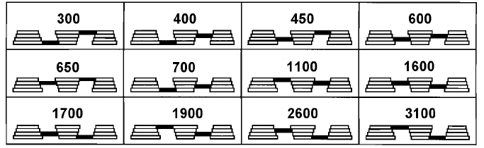
This drill press has 12 speeds as
listed below:
300 RPM 1100 RPM
400 RPM 1600 RPM
450 RPM 1700 RPM
600 RPM 1900 RPM
650 RPM 2600 RPM
700 RPM 3100 RPM
See inside of guard for specific place-
ment of belt on pulleys.
Think Safety
WARNING: Do not allow famil-
iarity (gained from frequent use of
your drill press) to become com-
monplace. Always remember that a
careless fraction of a second is suf-
ficient to inflict severe injury.
Plan Your Work
• Don’t force the tool. It will do the job
better and safer at the rate for which
it was designed.
• Use the right tool. Don’t force tool or
attachment to do a job it was not
designed to do.
• If any part of your drill press is miss-
ing, malfunctioning, has been dam-
aged or broken...such as the motor
switch, or other operating control, a
safety device or the power cord, turn
the drill press off and unplug it until
the particular part is properly
repaired or replaced.
• Never place your fingers in a posi-
tion where they could contact the
drill or other cutting tool if the work-
piece should unexpectedly shift or
your hand should slip.
• Keep guards in place and in working
order.
• To reduce the risk of injury from
parts thrown by the spring, follow
instructions exactly as given and
shown in adjusting spring tension of
quill.
• To prevent the workpiece from being
torn from your hands, spinning of
the tool, shattering the tool or being
thrown, always properly support
your work so it won’t shift or bind on
the tool:
- Always position backup material
(use beneath the workpiece) to
contact the left side of the column.
- Whenever possible, position the
workpiece to contact the left side of
the column - If it is too short or the
table is tilted, clamp solidly to the
table. Use table slots or clamping
ledge around the outside edge of
the table.
- When using a drill press vise,
always fasten it to a table.
- Never do any work “Freehand”
(hand holding workpiece rather
than supporting it on the table),
except when polishing.
- Securely lock head to column,
table support to column and table
to table support before operating
drill press.
- Never move the head or table
while the tool is running.
- Before starting the operation, jog
the motor switch to make sure the
drill or other cutting tool does not
wobble or cause vibration.
- If a workpiece overhangs the table
such that it will fall or tip if not held,
clamp it to the table or provide aux-
iliary support.
- Use fixtures for unusual operations
to adequately hold, guide and posi-
tion workpiece.
6
Safety Instructions For Drill Press (continued)
- Use the spindle speed recom-
mended for the specific operation
and workpiece material - check the
inside of the belt guard for drilling
information; for accessories, refer
to the instructions provided with
the accessories.
• Never climb on the drill press table,
it could break or pull the entire drill
press down on you.
• Turn the motor switch off and put
away the switch key when leaving
the drill press.
• To reduce the risk of injury from
thrown work or tool contact, do not
perform layout, assembly or setup
work on the table while the cutting
tool is rotating.
• Don’t overreach. Keep proper foot-
ing and balance at all times.
• Maintain tools with care. Keep tools
sharp and clean for best and safest
performance. Follow instructions for
lubricating and changing accessories.
Plan Ahead To Protect Your Eyes, Hands, Face and Ears
Dress for safety
• Do not wear loose clothing, gloves,
neckties or jewelry (rings, wrist
watches). They can get caught and
draw you into moving parts.
• Wear nonslip footwear.
• Tie back long hair.
• Roll long sleeves above the elbow.
• Noise levels vary widely. To reduce
the risk of possible hearing damage,
wear ear plugs or muffs when using
drill press for hours at a time.
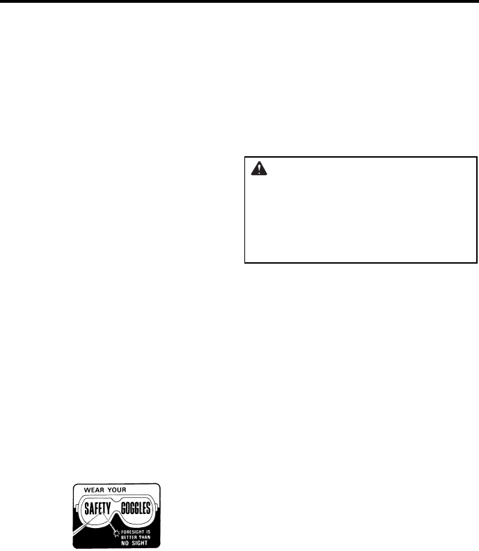
• Any power tool can throw foreign
objects into the eyes. This can result
in permanent eye damage. Always
wear safety goggles, not glasses
complying with ANSI Z87.1 (or in
Canada CSA Z94.3-99) shown on
package. Everyday eyeglasses
have only impact resistant lenses.
They are not safety glasses. Safety
goggles are available at many local
retail stores. Glasses or goggles not
in compliance with ANSI or CSA
could seriously hurt you when they
break.
• For dusty operations, wear a dust
mask along with safety goggles.
Reduce the Risk of Accidental
Starting.
• Make sure switch is “OFF” before
plugging drill press into a power out-
let.
WARNING: Don't allow familiar-
ity (gained from frequent use of
your drill press) to cause a careless
mistake. Always remember that a
careless fraction of a second is
enough to cause a severe injury.
Keep Children Away
• Keep all visitors a safe distance
from the drill press.
• Make sure bystanders are clear of
the drill press and workpiece.
Before Leaving The Drill Press
• Turn the drill press off.
• Wait for tool bit to stop spinning.
• Unplug the drill press.
• Make workshop child-proof. Lock
the shop. Disconnect master
switches. Remove the yellow switch
key. Store it away from children and
others not qualified to use the tool.
7
Glossary of Terms
Workpiece
The item on which the cutting operation is
being performed.
Drill Bit or Drill
The cutting tool used in the drill press to
make holes in a workpiece.
Backup Material
A piece of wood placed between the
workpiece and table...it prevents wood in
the workpiece from splintering when the
drill passes through the backside of the
workpice...also prevents drilling into the
table top.
Revolutions Per Minute (R.P.M.)
The number of turns completed by a spin-
ning object in one minute.
Spindle Speed
The R.P.M. of the spindle.
Backlash
The amount of handle movement or play
between adjacent moving parts.
Motor Specifications and Electrical Requirements
Power Supply and Motor Specifications
WARNING: To reduce the risk
of electrical hazards, fire hazards or
damage to the tool, use proper cir-
cuit protection. Your tool is wired at
the factory for operation using the
voltage shown. Connect tool to a
power line with the appropriate volt-
age and a 15-amp branch circuit.
Use a 15-amp time delay type fuse
or circuit breaker. To reduce the risk
of shock or fire, if power cord is
worn or cut, or damaged in any
way, have it replaced immediately.
The A-C motor used on this tool is a
totally enclosed fan cooled (TEFC), induc-
tion nonreversible type, having the follow-
ing specifications:
General Electrical Connections
DANGER: To reduce the risk of
electrocution:
1. Use only identical replacement
parts when servicing. Servicing
should be performed by a quali-
fied service technician.
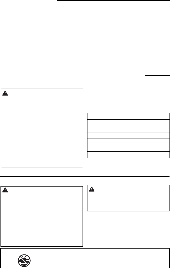
2. Do not use in rain or where floor
is wet.
This tool is intended for indoor
residential use only.
WARNING: Do not permit fin-
gers to touch the terminals of plug
when installing or removing the
plug to or from the outlet.
Rated H.P 1/2
Voltage 110-120
Amperes 8.0
Hertz (Cycles) 60
Phase Single
RPM 1700
Rotation of Shaft Clockwise
MEANING
SYMBOL
Do not expose to rain or use in damp locations.
SAVE THESE INSTRUCTIONS
8
Motor Specifications and Electrical Requirements
(continued)
110-120 Volt, 60 Hz. Tool
Information
NOTE: The plug supplied on your tool
may not fit into the outlet you are planning
to use. Your local electrical code may
require slightly different power cord plug
connections. If these differences exist
refer to and make the proper adjustments
per your local code before your tool is
plugged in and turned on.
In the event of a malfunction or break-
down, grounding provides a path of least
resistance for electric current to reduce
the risk of electric shock. This tool is
equipped with an electric cord having an
equipment grounding conductor and a
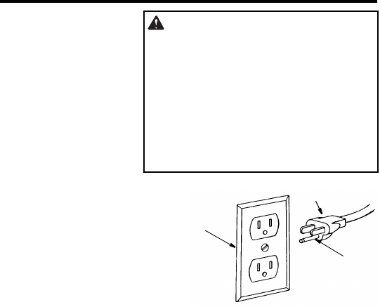
grounding plug, as shown. The plug must
be plugged into a matching outlet that is
properly installed and grounded in accor-
dance with all local codes and ordi-
nances.
Do not modify the plug provided. If it will
not fit the outlet, have the proper outlet
installed by a qualified electrician.
Improper connection of the equipment
grounding conductor can result in a risk of
electric shock. The conductor with insula-
tion having an outer surface that is green
with or without yellow stripes is the equip-
ment grounding conductor. If repair or
replacement of the electric cord or plug is
necessary, do not connect the equipment-
grounding conductor to a live terminal.
If the grounding instructions are not com-
pletely understood, or if you are in doubt
as to whether the tool is properly
grounded check with a qualified electri-
cian or service personnel.
WARNING: If not properly
grounded, this tool can cause an
electrical shock, particularly when
used in damp locations, in proximity
to plumbing, or outdoors. If an elec-
trical shock occurs there is the
potential of a secondary hazard,
such as your hands to hit the cut-
ting tool.
Properly
Grounded
3-Prong Plug
Grounding
Prong
3-Prong Outlet

9
Motor Safety Protection
IMPORTANT: To avoid motor damage,
this motor should be blown out or vacu-
umed frequently to keep sawdust from
interfering with normal motor ventilation.
1. Connect this tool to a power source
with the appropriate voltage for your
model and a 15-amp branch circuit
with a 15-amp time delay fuse or circuit
breaker. Using the wrong size fuse can
damage the motor.
2. If the motor won’t start, turn the switch
off immediately and unplug the tool.
Check the quill to make sure it turns
freely. If the quill is free, try to start the
motor again. If the motor still does not
start, refer to the "Motor Troubleshooting
Chart."
3. Fuses may "blow" or circuit breakers
may trip frequently if:
a. Motor Is Overloaded - Overloading
can occur if you feed too rapidly or
make too many start/stops in a short
time.
b. Line voltages should not be more than
10% above or below the nameplate
voltage. For heavy loads, however, the
voltage at motor terminals must equal
the voltage specified for your model.
c. Improper or dull drill bit is used.
4. Most motor troubles may be traced to
loose or incorrect connections, overload,
low voltage (such as small size wire in
the supply circuit) or to overly long sup-
ply circuit wire. Always check the con-
nections, the load and the supply circuit
whenever motor doesn’t work well.
Check wire sizes and length with the
Wire Size Chart shown.
Wire Sizes
NOTE: Make sure the proper extension
cord is used and is in good condition.
The use of any extension cord will cause
some loss of power. To keep this to a min-
imum and to prevent overheating and
motor burnout, use the table at right to
determine the minimum wire size
(A.W.G.) extension cord.
Use only 3-wire extension cords which
have 3-prong grounding type plugs and 3-
pole receptacles which accept the tools
plug.
Extension Cord
Length Gauge
(A.W.G.)
0-25
25-50
16
14
10
Unpacking and Checking Contents
Tools Needed
Unpacking
WARNING: For your own safety,
never connect plug to power source
outlet until all assembly steps are
complete, and you have read and
understood the safety and operat-
ing instructions.
The Drill Press is shipped complete in one
box.
1. Separate all “loose parts” from packing
materials and check each item with
illustration and “Table of Loose Parts.”
WARNING: To reduce the risk of
injury, if any parts are missing, do
not attempt to assemble the drill
press, plug in the power cord, or
turn the switch on until the missing
parts are obtained and installed
correctly.
2. Remove the protective oil that is applied
to the table and column. Use any ordi-
nary household type grease and spot
remover.
WARNING: To reduce the risk of
fire or toxic reaction, never use gas-
oline, naptha or similar highly vola-
tile solvents to remove protective
oil.
3. Apply a coat of paste wax to the table
and column to prevent rust. Wipe all
parts thoroughly with a clean dry cloth.
NOTE: Make certain all items are
accounted for before discarding any pack-
ing material.
Combination Square Must be True
Draw Light
Line on Board
Along this Edge
Straight Edge of
Board 3/4" Thick
This Edge Must b
e
Perfectly Straight
Should be no Gap or Overlap when Squar
e
is Flipped Over in Dotted Position
M
edium Screwdriver
Adjustable Wrench
Phillips Screwdriver
Combination Square
Framing
Square
11
List of Loose Parts
Item Description Qty.
A Head Asm. .......................................1
B Table................................................. 1
C Column Support Assembly...............1
D Base ................................................. 1
E Bag Chuck ....................................... 1
F Bag of Loose Parts ..(Quantity varies)
G Operator’s Manual ........................... 1
Loose Parts
A
B
D
E
G
F
C
M5 Hex “L” Wrench (1)
M3 Hex “L” Wrench (1)
M10 x 1.5-40 Long
Hex Head Bolt (4)
M24 Hex Box Wrench (1)
M10 x 1.5-12 Long
Hex Socket Set Screw (2)
Crank
Support Lock
Feed Handle (3)
Chuck Key (1)
Chuck (1)
Key Switch (1)
(With Set Screw) (1)
Handle (1)
12
Location and Function of Controls
1. Belt Tension Handle...Turn handle
counterclockwise to apply tension to
belt, turn handle clockwise to release
belt tension.
2. Head Lock Set Screws...Locks the
head to the column. Always have
them locked in place while operating
the drill press.
3. Feed Handle...For moving the chuck
up or down. One or two of the han-
dles may be removed if necessary
whenever the workpiece is of such
unusual shape that it interferes with
the handles.
4. Table Crank...Turn clockwise to ele-
vate table. Support lock must be
released before operating crank.
5. Chuck...Holds drill bit or other rec-
ommended accessory to perform
desired operations.
6. Depth Scale...Allows operator to
adjust drill press to drill to a desired
depth.
7. Drill “On-Off” Switch...Has locking
feature to prevent unauthorized and
possible hazardous use by children
and others.
8. Light “On-Off” Switch...Turns the
light on and off.
9. Depth Scale Lock...Locks the depth
scale at selected depth.
10. Spring Cap...Provides means to
adjust quill spring tension.
11. Table Lock...Allows table to be
rotated in various positions and
locked.
12. Table Bevel Lock...Locks the table
in any position from 0°- 45°.
13. Bevel Scale...Shows degree table is
tilted for bevel operations. Scale is
mounted on side of arm.
14. Support Lock Handle...Tightening
locks table support to column. Always
have it locked in place while operat-
ing the drill press.
15. Chuck Key...Used to tighten drill in
the chuck and also to loosen the
chuck for drill removal.
16. Storage Tray...Conveniently holds
drill bits and other accessories.
17. Belt Tension Lock Handles...Tight-
ening handles locks motor bracket
support to maintain correct belt dis-
tance and tension.
Note and follow the safety warnings
and instructions that appear on the
panel on the right side of the head.
17
12
13
14
1
5
1
6
2
3
4
5
6
7
8
9
10
11
1
13
Assembly
WARNING: To reduce the risk of
injury from unexpected starting or
electrical shock, never connect plug
to outlet until all assembly steps are
completed and you read and under-
stand all instructions.
Assembly of Base/Column
1. Locate four (4) 10mm dia. x 40mm long
bolts among loose parts bag.
2. Position base on floor. Remove protec-
tive covering and discard.
3. Remove protective sleeve from column
tube and discard. Place column assem-
bly on base, and align holes in column
support with holes in base.
4. Install a bolt in each hole through col-
umn support and base and tighten with
adjustable wrench.
5. Locate table crank and support lock from
loose parts.
6. Install support lock from left side into
table support and tighten by hand.
7. Install table crank assembly and tighten
set screw with a 3mm hex “L” wrench.
Do not overtighten. Set screw should be
tightened against the flat section of the
shaft.
NOTE: To minimize crank backlash,
tighten support lock, rotate elevation
worm shaft clockwise, then assemble
crank tight against table support and
tighten set screw.
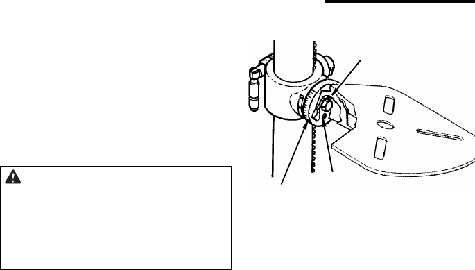
8. Check column collar for proper adjust-
ment. Collar should not be angled on the
column and it should be positioned so
rack will slide freely in collar when table
is rotated 360° around column tube. If
readjusted, only tighten set screw
enough to keep collar in place.
NOTE: To reduce the risk of column or
collar damage, do not overtighten set
screw.
Base
10mm Dia. x 40mm
Hex Head Bolt (4)
Column
Support
Column
S
upport
Lock
Table
Support
Table
Support Elevation
Worm Sha
ft
Handle
Table
Crank
Column
Collar
Rack
Column
Do Not
Overtighte
n
Set Screw
14
Assembly (continued)
Installing The Table
1. Loosen support lock and raise table
support by turning table crank clock-
wise until support is at a working
height level. Tighten support lock.
2. Remove protective covering from table
and discard. Loosen table lock, place
table in table support and tighten table
lock (located under table) by hand.
NOTE: If table won’t fit into table support
easily, pry open table support with a flat
blade screwdriver.
Installing the Storage Tray
1. Locate the two piece storage tray, (2)
two 5mm dia. x 60 mm long screw, and
(2) two 5 mm hex nuts.
2. Attach to the column as shown. Make
sure the storage tray is located above
the column collar. Be careful not to over-
tighten the nuts.
Rack
Table
Cran
k
Column
Table
Support
Support
Lock
Table
Table
Support
Table
Lock
Support
Lock
Pan Head Screw
5mm x 60mm
(Not Actual Size) Hex Nu
t
5 mm
Storage Tray
Column
Collar
15
Installing the Head
CAUTION: The head assembly
weighs about 80 pounds. To reduce
the risk of back injury get help to lift
the head.
1. Locate (2) two 10mm dia. x 12mm long
set screws in loose parts bag.
2. Remove protective bag from head
assembly and discard. Carefully lift head
above column tube and slide it onto col-
umn making sure head slides down over
column as far as possible. Align head
with table and base.
3. Install a set screw in each hole (as indi-
cated) on the right side of the head, and
using a 5mm hex “L” wrench, tighten the
two head lock set screws.
10mm Dia. x 12mm
Set Screw
Head
Column
Head Lock
Set Screws
Head
16
Assembly (continued)
Pulley Alignment and Speed
Adjustment
Checking Pulley(s) Alignment
WARNING: To reduce the risk of
injury due to accidental starting
always turn drill press off and
remove switch key before making
belt adjustments.
Pulley alignment is set at the factory and
should not require further adjustment. If
the pulleys or motor are removed for ser-
vice, follow the pulley alignment instruc-
tions below.
1. Place the idler pulley from loose parts
bag into the head as shown. Place
belts from loose parts bag on pulleys
following speed adjustment instruc-
tions below.
2. Place a straightedge such as a piece of
wood, metal, or framing square across
the top of pulleys.
3. The top of all three pulleys should touch
the straightedge.
Straightedge
Belt
Tension
Lock
Handle
Motor
Mount
Nuts Mot
or
Lower
Belt
Guard
4. If not:
• Loosen the motor mount nuts.
• Move the motor until the pulleys are
in line.
• Retighten the motor mount nuts.
NOTE: To avoid rattles or other noise,
motor frame must not touch lower belt
guard.
Speed Adjustment
1. Release belt tension lock handles
located on each side of drill press head
by turning them counterclockwise.
2. Loosen belt tension by turning belt ten-
sion handle clockwise.
3. Use speed chart inside belt guard to
choose speed for drilling operation.
Install belts in correct position for desired
speed. The longer of the two belts is
always positioned between the spin-
dle pulley and idler pulley.
IMPORTANT: Visually check to make sure
the four ribs on the belt are placed into the
four pulley grooves.
Belt
Tensio
n
Handl
e
Idler
Spindle
Pulley Pulley
Properly aligned belt should not
touch the stepped surface on
the pulley
17
Tensioning Belt
1. Apply tension to belt by turning belt
tension handle counterclockwise until
belt deflects approximately 1/2 inch by
thumb pressure at its center.
2. Tighten belt tension lock handles.
NOTE: Over tensioning belt may cause
motor not to start or damage bearings.
3. If belt slips while drilling, readjust belt
tension. Also make sure the ribs in the
belt are aligned with grooves in the pul-
ley.
Installing Feed Handles
1. Locate three (3) feed handles among
loose parts.
2. Screw the feed handles into the
threaded holes in the hub and tighten.
3. Tighten feed handles using the open
end of the M24 hex box wrench included
with drill press.
Installing the Drill Chuck
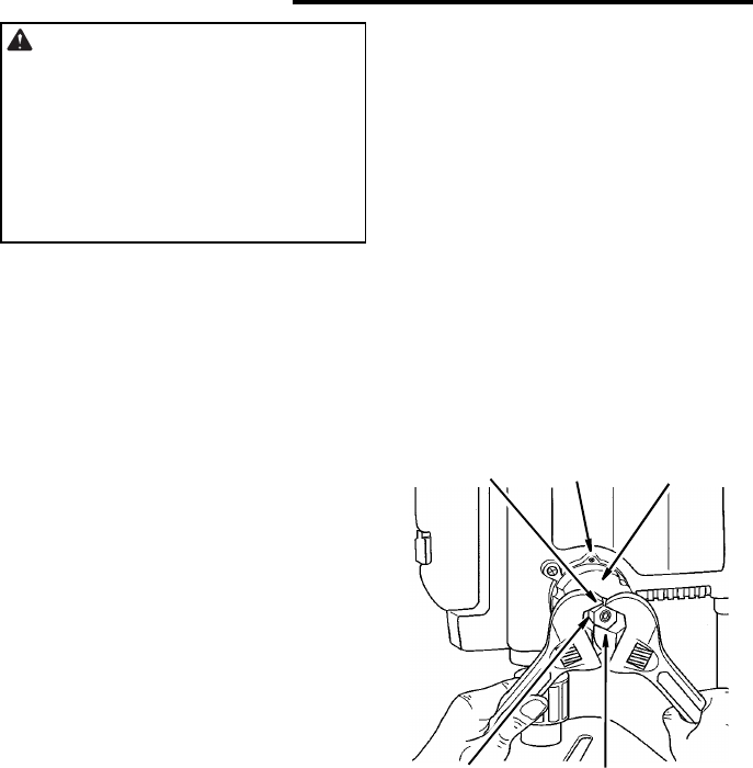
1. Clean the tapered surfaces on the
chuck and spindle with a clean cloth.
Make sure there are no foreign parti-
cles sticking to these surfaces. The
slightest piece of dirt on these surfaces
will prevent the arbor from seating
properly. This will cause the drill to
“wobble”.
2. Slide chuck into spindle of drill press.
3. Push up on chuck assembly as you
rotate it.
Belt Tension
Lock Handl
e
Belt
Tensio
n
Handl
e
Feed
Handle
Tighten Usin
g
M24 Wrench
Hub
Quill
Spindle
Tapered
Arbor
Surfac
e
Chuc
k
Chuck Body
Sleev
e
Surface
Tapere
d
18
Assembly (continued)
4. Unlock support lock and raise table so
its about two (2) inches below tip of
chuck.
5. Turn chuck sleeve clockwise and open
jaws in chuck completely.
6. Place a piece of wood on table. Turn
feed handles counterclockwise and
force chuck against table until chuck is
secure.
Support
Lock
Chuck
Chuck
Sleeve
Feed
Handle
Wood
19
Installing Light Bulb
WARNING: To reduce the risk of
electrical shock, unplug the tool before
installing light bulb.
1. Remove the amber colored lens cover
by removing the two Phillips screws.
2. Install a light bulb (not larger than 60
watt) into the socket inside the head.
3. Replace the lens cover.
Adjusting the Table Square To
Head
NOTE: The combination square must be
“true”. See “Unpacking and Checking
Contents” section for method.
1. Insert precision round steel rod or
straight drill bit approximately 3” long
into chuck and tighten.
2. With table raised to working height and
locked on column, place combination
square flat on table beside rod or bit.
3. If an adjustment is necessary, loosen the
set screw under bevel lock with 3mm “L”
wrench, then loosen the table bevel lock
bolt with the 24mm hex box wrench
(included). (This adjustment is located
under the table).
4. Align the table square to the rotor bit by
rotating table until the square and rod or
bit are in line.
5. Retighten table bevel lock.
6. Retighten set screw.
Bevel Scale
NOTE: The bevel scale has been
included to provide a quick method for
beveling the table to approximate angles.
If precise accuracy is necessary, a
square, or other precision measuring tool
should be used to position the table.
1. To use the bevel scale do the following.
a. Loosen set screw and table bevel
lock (see step 3 above).
b. Move table so desired angle on bevel
scale is straight across from zero line
on pointer.
c. Retighten table bevel lock and set screw.
Remove Screws
Set
Screw Table Bevel
Lock
Table
Pointer Scale
Table
20
Assembly (continued)
Converting From Right Hand
Operation to Left Hand Operation
The drill press is shipped from the factory
with feed handles set-up for right hand
operation. However, if desired, the drill
press feed handles can be converted to
left hand operation.
WARNING: For your own safety
turn switch “OFF” and remove plug
from power source outlet before
making any adjustments.
1. To help keep the drill chuck from falling
on to the floor, place a piece of scrap
wood on top of the table and raise the
table until it engages the chuck.
CAUTION: Releasing the spring
assembly without proper support of
the chuck will allow the quill assem-
bly to drop on top of the drill press
table.
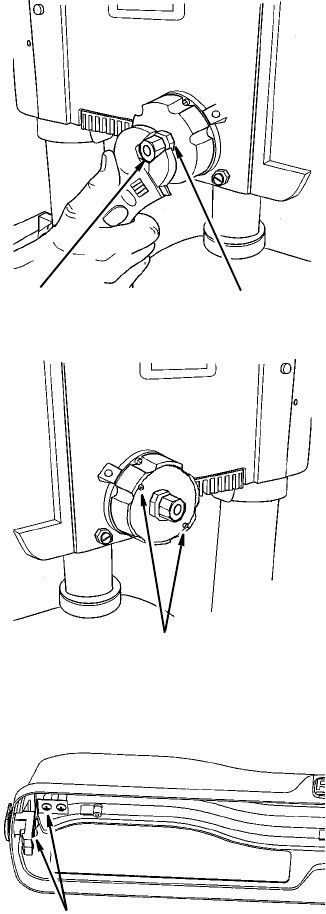
2. Firmly hold spring housing against head
so it remains engaged with the 4mm
cap screw. Remove both M12 nuts and
M12 washer from the feed handle
assembly shaft.
3. Use both hands to firmly grasp the
spring assembly. Pull the spring
assembly slightly away from the drill
press, disengaging the spring housing
from the cap screw. While firmly hold-
ing the housing, allow the spring
assembly to unwind clockwise until
the spring tension is relieved.
CAUTION: To prevent injury, be
careful not to allow the spring
assembly to rapidly unwind.
4. Remove the spring assembly.
5. Slide the feed handle assembly out
from the right side of the head.
6. Remove the bushing located on the
left of the head assembly as shown. It
may be necessary to tap this bushing
out from the right side. Reinstall this
bushing on the right side of the drill
press.
M12
Nuts
4mm Ca
p
Screw
Remove 4mm
Cap Screws
Remove
Bushing
21
7. Remove the 4mm socket head cap
screw from the left side of the drill
press and install in the same position
on the right side of the drill press.
Tighten screw.
8. Remove the 6mm stop pin screw from
the right side of the drill press and
install in the left side of the drill press
as shown. Tighten stop pin screw.
9. Install the feed handle assembly and
depth stop ring on the left side of the
drill press. With the chuck at its high-
est possible position, turn the depth
scale clockwise until it stops and
tighten the depth scale lock. This will
prevent the quill from dropping while
installing the spring.
10. Install the spring assembly on the right
side of the drill press, making sure the
two housing screw heads face out-
wards. The center tab of the spring
must go in the slot on the feed handle
assembly.
If necessary, use a screwdriver to align
and keep spring centered during installa-
tion.
11. Replace M12 washer and screw the
outer and inner nuts back on the feed
handle assembly. Hold the spring
assembly in place and loosely assem-
ble both nuts. See following page for
quill return spring adjustment.
12. Remove the depth scale and reposi-
tion so numbers are legible as shown.
13. Remove the depth scale indicator
from the right side of the drill press
and reinstall on the left side of the drill
press.
14. Remove the scrap wood from the
table top.
Install 6mm
Stop Scre
w
Right side housing screws
face outward as shown
Install Feed Handl
e
Assembly
Remove Depth Scale
and Reposition
Install Dept
h
Scale
Indicator
22
Assembly (continued)
WARNING: For your own safety
turn switch “OFF” and remove plug
from power source outlet before
making any adjustments. To reduce
the risk of injury from thrown parts
due to spring release, follow
instructions carefully and wear eye
goggles.
Quill Return Spring
NOTE: The return spring tension is set at
the factory and should not require further
adjustment.
If you switched your drill press from right
hand operation to left hand operation, fol-
low the procedure below to adjust spring
tension.
1. With the chuck at its highest possible
position, turn the depth scale clockwise
until it stops and tighten the depth
scale lock. This will prevent the quill
from dropping while tensioning the
spring.
NOTE: For right hand operation (feed
handle on right side) turn the depth scale
counterclockwise until it stops and
tighten the depth scale lock.
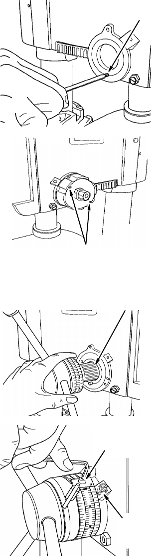
2. Check to make sure spring housing is
mounted correctly. When spring hous-
ing is placed on the right side (feed
handles mounted on left side), the
housing screws face out as shown.
When spring housing is placed on the
left side (feed handles mounted on
right side), the housing screws face
toward the head as shown.
3. Lower table for additional clearance.
4. Firmly hold the spring assembly
against the head keeping it engaged
with the 4mm cap screw while loosen-
ing and removing the outer nut only.
5. Loosen inner nut (approximately 1/4
inch) and disengage spring housing
from the 4mm cap screw. Using both
hands turn spring clockwise to the
next notch and engage with the 4mm
cap screw.
Notch
Nut (Outer)
Nut (Inner)
Spring
Cap
4 mm Cap
Screw
23
NOTE: For right hand operation (feed
handle on right side) turn spring counter-
clockwise to the next notch and engage
with the 4mm cap screw.
6. Finger tighten inner nut against spring
housing. Do not overtighten as this will
restrict quill movement.
7. Loosen depth scale lock and check
quill return by rotating feed handles,
lowering quill.
8. Proper tension is achieved when quill
returns gently to full up position when
released from 3/4” depth.
9. If there is not enough tension on
spring, repeat steps 5-8 moving only
one notch each time and checking
tension after each repetition.
10. After adjusting spring, replace outer
nut and tighten to inner nut. But do not
overtighten against inner nut.
11. Check quill movement to make sure it
is smooth and unrestricted. If move-
ment is too tight, loosen outer nut and
slightly loosen inner nut until unre-
stricted. Retighten outer nut.
Adjusting Belt Latch Guard
The button latch is adjusted at the factory
to be self latching when the pulley guard
lid is closed. If adjustment is needed,
loosen the two screws securing the latch
to the lid and move latch back until the lid
closes without depressing the button. The
button can also be adjusted up and down
to assure lid closes tight by loosening the
two screws in back of the latch button,
and moving the button up or down as
needed.
Nut (Outer) Nut (Inner)
Left side housing screws
face towards head as shown
Right side housing screws
face outward as shown
Latch Adjusting Screws
24
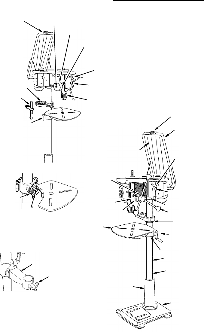
Getting To Know Your Drill Press
Feed Spring
Adjustment
Feed Spring
18 Spring
Cap
Light “On-Off”
Switch
23 Table
28 Drill “On-Off”
Switch
26 Chuck
Key
16 Depth Scale
Indicator 15 Depth
14 Table
10 Rack
9 Table Cran
k
8 Table Support
7 Column
6 Feed Handl
e
5 Head Lock
4 Belt Tensio
n
Handle
3 Belt Tensio
n
Lock Handle
12 Column
Support
24 Bevel
13 Column
25 Support
Lock 2 Belt Guard
11 Base
Scale
17
Depth Scale
Lock
1 Drill Speed Table
(Inside Belt Guard)
19 Belt Guard
20 Chuck
Lock
27 Storage
Tray
22 Table Bevel
Lock
(Under Table)
21 Arm
Scale
Collar
19 Belt Guard Latch
Latch
25
Spindle Speed in R.P.M.
1. Drill Speed Table...Drill Speed can be
changed by placing the belt in any one
of the stepped pulleys. The spindle
speed chart, as shown above, lists
belt positions for the various spindle
speeds.
2. Belt Guard...Covers pulleys and belt
during operation of drill press.
3. Belt Tension Lock Handle...Tighten-
ing handle locks motor bracket sup-
port to maintain correct belt distance
and tension.
4. Belt Tension Handle...Turn handle
counterclockwise to apply tension to
belt, turn handle clockwise to release
belt tension. Refer to section “Assem-
bly-Installing and Tensioning Belt”.
5. Head Lock Set Screws...Lock the
head to the column. Always have
them locked in place while operating
the drill press.
6. Feed Handle...For moving the chuck up
or down. One or two of the handles may
be removed if necessary whenever the
workpiece is of such unusual shape that
it interferes with the handles.
7. Column Collar... Holds the rack to the
column. Rack remains movable in col-
lar to permit table support movements.
8. Table Support...Travels up and down
on column. Supports arm and crank.
9. Table Crank...Turn clockwise to ele-
vate table. Support lock must be
released before operating crank.
10. Rack...Combines with gear mecha-
nism to provide easy elevation of table
by hand operated table crank.
11. Base...Supports drill press. For addi-
tional stability, holes are provided in
base to bolt drill press to floor. (See
“Additional Safety Instructions for Drill
Presses”.
12. Column Support...Supports column,
guides rack, and provides mounting
holes for column to base.
13. Column...Connects head, table and
base on a one-piece tube for easy
alignment and movement.
14. Table...Provides working surface to
support workpiece.
15. Depth Scale...Shows depth of hole
being drilled in inches and millimeters.
16. Depth Scale Indicator...Indicates
drilling depth selected on depth scale.
17. Depth Scale Lock...Locks the depth
scale to selected depth.
18. Spring Asm....Provides means to
adjust quill spring tension.
19. Belt Guard Latch...Press button to
raise belt guard.
20. Chuck...Holds drill bit or other recom-
mended accessory to perform desired
operations.
21. Arm...Extends beyond table support
for mounting aligning the table.
22. Table Bevel Lock...Locks the table in
any position from 0°- 45°.
23. Table Lock...Table can be rotated in
various positions and locked.
24. Bevel Scale...Shows degree table is
tilted for bevel operations. Scale is
mounted on table support, if it is to be
used for quick reference where accu-
racy is not critical.
26
Getting To Know Your Drill Press (continued)
25. Support Lock...Tightening locks table
support to column. Always have it
locked in place while operating the
drill press.
26. Chuck Key...It is a self ejecting chuck
key which will “pop” out of the chuck
when you let go of it. This action is
designed to help prevent throwing of
the chuck key from the chuck when
power is turned “ON”. Do not use any
other key as a substitute, order a new
one if damaged or lost.
27. Storage Tray...Conveniently holds
drill bits and other accessories.
28.On-Off Switch...Has locking feature.
This feature is intended to prevent
unauthorized and possible hazardous
use by children and others.
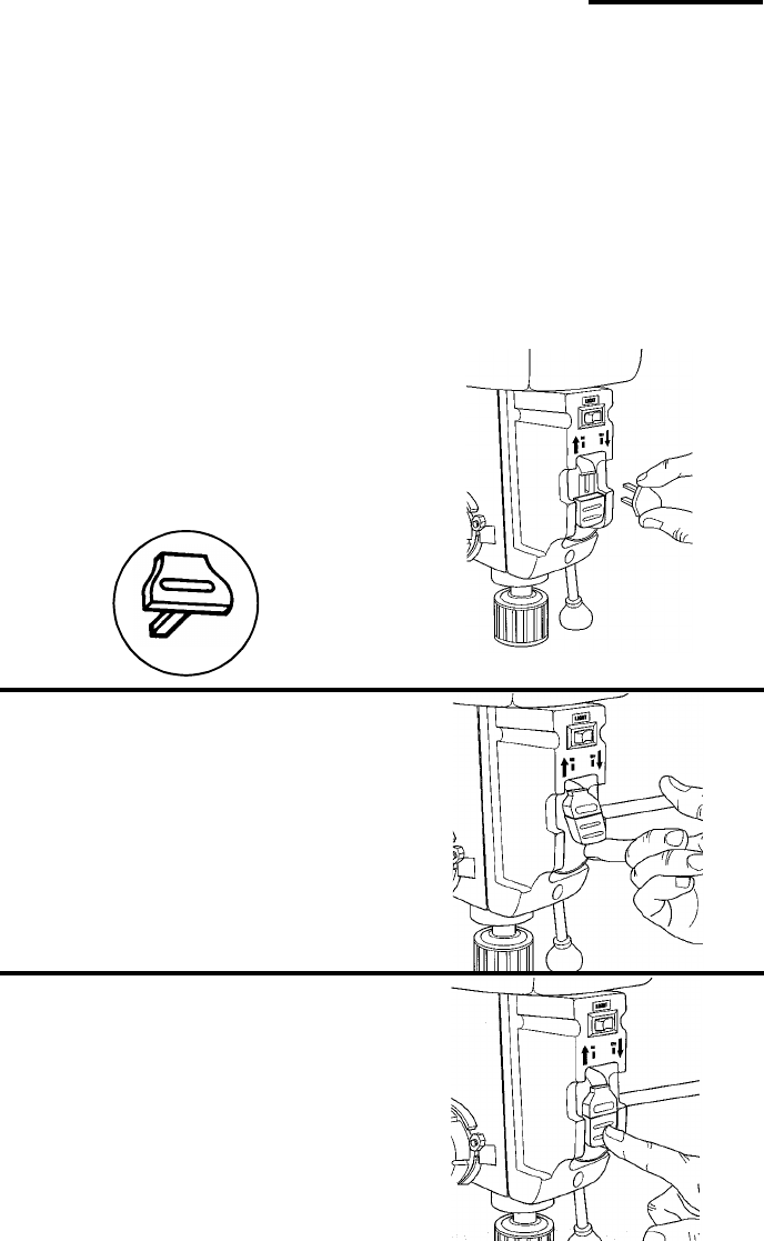
Insert key into switch.
NOTE: Key is made of yellow plastic.
To turn drill ON, insert finger under switch
lever and pull.
To turn drill OFF, push lever in.
NOTE: In an emergency: If the drill bit
binds, stalls, stops or tends to tear the
workpiece loose, you can quickly turn the
drill off by hitting the switch with the palm
of your hand.
Key
27
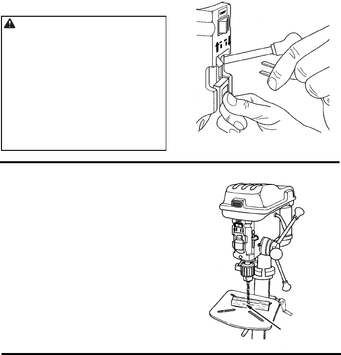
To lock switch in OFF position, hold
switch IN with one hand and remove key
with other hand.
WARNING: For your own safety,
always push the switch “OFF” when
drill press is not in use, remove key
and keep it in a safe place, also, in
the event of a power failure (all of
your lights go out) or blown fuse or
tripped circuit breaker, turn switch
off, lock it and remove the key. This
will prevent the drill press from
starting up again when the power
comes back on.
Drilling to a Specific Depth
To drill a blind hole (not all the way
through) to a given depth, proceed as fol-
lows.
1. Mark the depth of the hole on the work-
piece.
2. Loosen the depth scale lock.
3. With the switch OFF, bring the drill bit
down until the tip of lips of the bit are
even with the mark.
4. Turn the depth scale counterclockwise
until it stops moving.
5. Tighten the depth scale lock.
6. The drill bit will stop at this depth until the
depth scale is readjusted.
Another Way - Depth Scale
1. With the power off, loosen the depth
scale lock.
2. Place workpiece on table. Adjust table
until the tip of the drill bit is just a little
above the top of the workpiece, turn the
depth scale counterclockwise to zero.
3. Turn the depth scale clockwise until the
depth scale indicator points to the
desired drilling depth on the depth scale.
4. Tighten the depth scale lock.
5. The chuck or drill will now be stopped
after traveling downward the distance
selected on the depth scale.
1/4" Mark
28
Getting To Know Your Drill Press (continued)
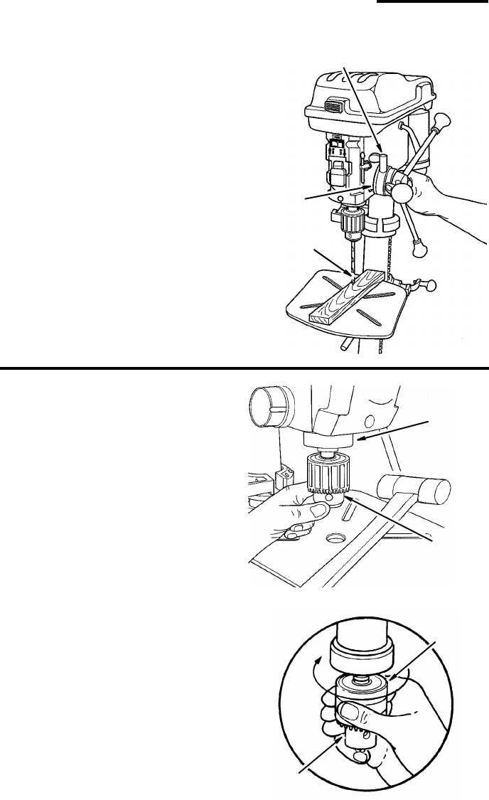
Locking Chuck at Desired Depth
1. With the switch off, loosen the depth
scale lock.
2. Turn the feed handles until the chuck is
at the desired depth. Hold feed handles
at this position.
3. Turn the depth scale clockwise until it
stops.
4. Tighten the depth scale lock.
5. The chuck will now be held at this depth
when the feed handles are released.
Removing Chuck and Arbor
1. Open jaws of chuck as wide as they will
go by turning chuck sleeve.
2. Using a downwards motion carefully tap
on the chuck with a mallet while slowly
turning the chuck with your other hand.
Make sure and hold onto the chuck to
prevent it from dropping when it is
released from the spindle nose. Insert
drift key into key holes.
NOTE: If chuck is difficult to remove,
place dowel rod on top surface of chuck
and tap dowel with hammer.
Depth
Scale Lock
Depth
Adjust to
D
esired Depth
Scale
Drift Ke
y
Chuck
Chuck Body
Chuck
Sleeve
Chuck
Sleeve

29
Safety Instructions for Basic Drill Press Operation
Read the following instructions for
operating your drill press to get the
best results and to minimize the likeli-
hood of personal injury.
WARNING: For your own safety,
always observe the safety precau-
tions here and on pages 2 thru 6.
Plan Ahead To Protect Your Eyes, Hands, Face and Ears
Dress for safety
• Do not wear loose clothing, gloves,
neckties or jewelry (rings, wrist
watches). They can get caught and
draw you into moving parts.
• Wear nonslip footwear.
• Tie back long hair.
• Roll long sleeves above the elbow.
• Noise levels vary widely. To reduce
the risk of possible hearing damage,
wear ear plugs or muffs when using
drill press for hours at a time.
Plan Your Work
• Don’t force the tool. It will do the job
better and safer at the rate for which
it was designed.
• Use the right tool. Don’t force tool or
attachment to do a job it was not
designed to do.
• If any part of your drill press is miss-
ing, malfunctioning, has been dam-
aged or broken...such as the motor
switch, or other operating control, a
guard, safety device or the power
cord, turn the drill press off and
unplug it until the particular part is
properly repaired or replaced.
• Never place your fingers in a posi-
tion where they could contact the
drill or other cutting tool if the work-
piece should unexpectedly shift or
your hand should slip.
• To reduce the risk of injury from
parts thrown by the spring, follow
instructions exactly as given and
shown in adjusting spring tension
of quill.
• To prevent the workpiece from being
torn from your hands, spinning of
the tool, shattering the tool or being
thrown, always properly support
your work so it won’t shift or bind on
the tool:
- Always position backup material
(use beneath the workpiece) to
contact the left side of the column.
- Whenever possible, position the
workpiece to contact the left side of
the column - If it is too short or the
table is tilted, clamp solidly to the
table. Use table slots or clamping
ledge around the outside edge of
the table.
- When using a drill press vise,
always fasten it to a table.
- Never do any work “Freehand”
(hand holding workpiece rather
than supporting it on the table),
except when polishing.
- Securely lock head to column,
table support to column and table
to table support before operating
drill press.
- Never move the head or table
while the tool is running.
- Before starting the operation, jog
the motor switch to make sure the
drill or other cutting tool does not
wobble or cause vibration.
- If a workpiece overhangs the table
such that it will fall or tip if not held,
clamp it to the table or provide aux-
iliary support.
- Use fixtures for unusual operations
to adequately hold, guide and posi-
tion workpiece.

30
Getting To Know Your Drill Press (continued)
- Use the spindle speed recom-
mended for the specific operation
and workpiece material - check the
inside of the belt guard for drilling
information; for accessories, refer
to the instructions provided with
the accessories.
• Never climb on the drill press table,
it could break or pull the entire drill
press down on you.
• Turn the motor switch off and put
away the switch key when leaving
the drill press.
• To reduce the risk of injury from
thrown work or tool contact, do not
perform layout, assembly or setup
work on the table while the cutting
tool is rotating.
• Don’t overreach. Keep proper foot-
ing and balance at all times.
• Maintain tools with care. Keep tools
sharp and clean for best and safest
performance. Follow instructions for
lubricating and changing accesso-
ries.
Use Only Accessories Designed For This Drill Press To Reduce
the Risk of Serious Injury From Thrown Broken Parts Or Work
Pieces
• When cutting large diameter holes:
- Clamp the workpiece firmly to the
table. Otherwise the cutting may
grab and spin it at high speed.
- Use only one piece, cup-type, hole
cutters.
-Do not use fly cutters or multi-part
hole cutters as they can come
apart or become unbalanced in
use.
- Keep speed below 1500 R.P.M.
• Drum sanders must never be oper-
ated on this drill press at a speed
greater than 1800 R.P.M.
• Do not install or use any drill that
exceeds 7” in length or extends 6”
below the chuck jaws. They can
suddenly bend outward or break.
• Do not use wire wheels, router bits,
shaper cutters, circle (fly) cutters or
rotary planers on this drill press.
Basic Drill Press Operation
Installing Drills
Insert drill into chuck far enough to obtain
maximum gripping of the chuck jaws. The
jaws are approximately 1" long. When
using a small drill do not insert it so far
that the jaws touch the flutes (spiral
grooves) of the drill. Make sure that the
drill is centered in the chuck before tight-
ening the chuck with the key.
Tighten the drill sufficiently, so that is does
not slip while drilling.
Turn the chuck key clockwise to tighten,
counterclockwise to loosen.
Chuck Ke
y
Chuck
Jaws
31
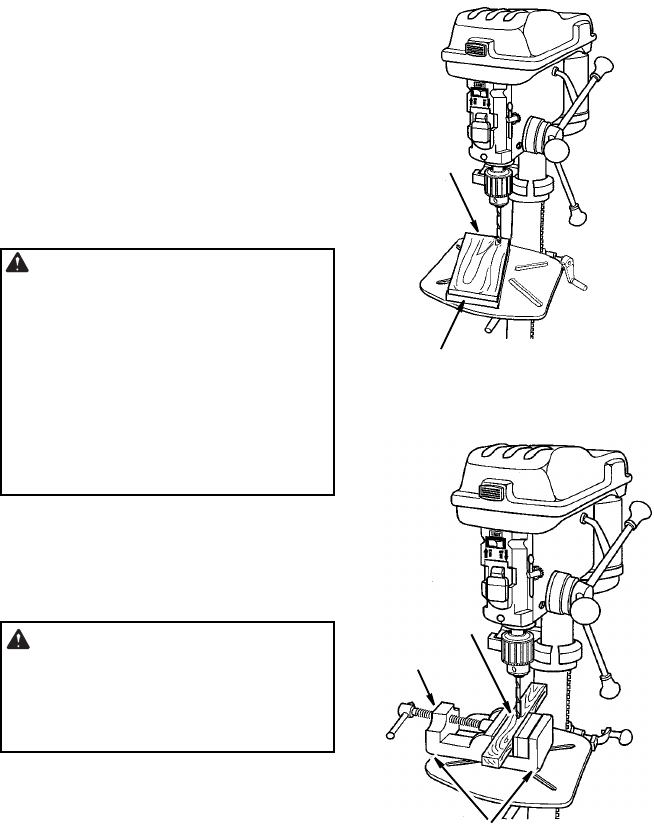
Positioning Table and Workpiece
Lock the table to the column in a position
so that the tip of the drill is just a little
above the top of the workpiece.
Always place a piece of backup material
(wood, plywood, etc.) on the table under-
neath the workpiece. This will prevent
“splintering” or making a heavy burr on
the underside on the workpiece as the
drill breaks through. To keep the backup
material from spinning out of control, it
must contact the left side of the column,
as illustrated.
WARNING: To prevent the work-
piece or the backup material from
being torn from your hand while
drilling, position them against the
left side of the column. If the work-
piece or the backup material are not
long enough to reach the column,
clamp them to the table. Failure to
do this could result in personal
injury.
For small pieces that cannot be clamped
to the table, use a drill press vise (not
included).
WARNING: The vise must be
clamped or bolted to the table to
reduce the risk of injury from spin-
ning work and vise or tool break-
age.
Workpiece
Backup
Material
Workpiece
Drill Press
Vise
Bolt or Clamp Vise Securely
32
Tilting Table
To use the table in a bevel (tilted) position,
loosen the set screw under table bevel
lock with hex “L” wrench. Loosen bevel
lock bolt with the 24mm flat wrench
(included).
Tilt table to desired angle by reading
bevel scale. Retighten bevel lock and set
screw.
WARNING: To reduce the risk of
injury from spinning work or tool
breakage, always clamp workpiece
and backup material securely to
table before operating drill press
with the table tilted.
To return table to original position: Loosen
set screw and bevel lock, tilt table back to
0° on bevel scale and retighten set screw,
then tighten bevel lock.
Hole Location
Make a dent in the workpiece where you
want the hole, using a center punch or a
sharp nail.
Before turning the switch on, bring the drill
down to the workpiece lining it up with the
hole location.
Feeding
Pull down on the feed handles with only
enough effort to allow the drill to cut.
Feeding too slowly might cause the drill to
burn. Feeding too rapidly might stop the
motor, cause the belt or drill to slip, tear
the workpiece loose or break the drill bit.
When drilling metal, it may be necessary
to lubricate the tip of the drill with cutting
oil or motor oil to prevent burning of the
drill tip.
Bevel Lock
Set Screw
Bevel Scale
Basic Drill Press Operation (continued)
33
Maintenance
Maintenance
WARNING: For your own safety,
turn switch “OFF” and remove plug
from power source outlet before
maintaining or lubricating your drill
press.
A coat of automotive type paste wax
applied to the table and column will help
to keep the surfaces clean.
WARNING: To reduce the risk of
shock or fire hazard, if the power
cord is worn or cut, or damaged in
any way, have it replaced immedi-
ately.
Lubrication
All of the ball bearings are packed with
grease at the factory. They require no fur-
ther lubrication.
Periodically lubricate the table elevation
mechanism, the splines (grooves) in the
spindle, and the rack (teeth of the quill).
See “Getting to Know Your Drill Press”.
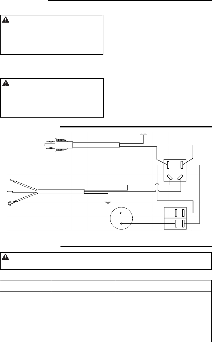
Wiring Diagram
Troubleshooting
WARNING: For your own safety, turn switch “OFF” and always remove
plug from power source outlet before troubleshooting.
Consult your Authorized Service Center if for any reason motor will not run.
Trouble Probable Cause Remedy
Noisy Operation 1. Incorrect belt tension.
2. Dry spindle.
3. Loose spindle pulley
4. Loose motor pulley
1. Adjust tension. See “Installing and
Tensioning Belt” section.
2. Lubricate spindle. See “Lubrication”
section.
3. Checking tightness of retaining nut
on pulley, and tighten if necessary.
4. Tighten set screws in pulleys.
Motor Cord
Switch Locking
Switch Rocker (Light)
Black
Black
Socket Asm Bulb
White
White
White
Black
Green
Green
Black
White
Cord w/Plug
Green Lead 3" White
Lea
d
3"
Blac
k
(On/Off)
Top
To
M
otor

34
Troubleshooting (continued)
Trouble Probable Cause Remedy
Drill bit burns 1. Incorrect speed
2. Chips not coming out of
hole
3. Dull drill bit
4. Feeding too slow
5. Not lubricated
1. Change speed. See “Getting to
Know Your Drill Press” section.
2. Retract drill bit frequency to clear
chips
3. Resharpen drill bit
4. Feed fast enough, allow drill bit to
cut
5. Lubricate drill bit. See “Basic Drill
Press Operation” section.
Drill bit leads off,
hole not round
1. Hard grain in wood or
lengths of cutting lips
and/or angles not
equal.
2. Bent drill bit
1. Resharpen drill bit correctly
2. Replace drill bit
Wood splinters on
underside
1. No “backup material”
under workpiece
1. Use “backup material”. See “Basic
Drill Press Operation” section.
Workpiece torn
loose from hand
1. Not supported or
clamped properly
1. Support or clamp workpiece. See
“Basic Drill Press Operation” sec-
tion.
Drill bit binds in
workpiece
1. Workpiece pinching
drill bit or excessive
feed pressure.
2. Improper belt tension
1. Support or clamp workpiece. See
“Basic Drill Press Operation” sec-
tion.
2. Adjust tension. See “Installing and
Tensioning Belt” section.
Excessive drill bit
runout or wobble.
1. Bent drill bit
2. ‘Worn spindle bearings
3. Drill bit not properly
installed in chuck
4. Chuck not properly
installed
1. Use a straight drill bit.
2. Replace bearings
3. Install drill bit properly. See “Basic
Drill Press Operation” section.
4. Install chuck properly, refer to
“Assembly- Installing the Chuck”.
Quill returns too
slow or too fast
1. Spring has improper
tension
1. Adjust spring tension. See “Adjust-
ments - Quill Return Spring” section.
Chuck will not stay
attached to spin-
dle, it falls off when
trying to install.
1. Dirt, grease or oil on
the tapered inside sur-
face of chuck or on the
spindles tapered sur-
face.
1. Using a household detergent, clean
the tapered surface of the chuck
and spindle to remove all dirt,
grease and oil.
Chuck rotates but
does not deliver
sufficient torque to
properly drill.
1. Spindle pulley nut (part
no. 821742) loose.
1. Turn nut counterclockwise to
tighten. (The nut has left-hand
threads.) See Repair Parts - Figure 1
for location of pulley nut.
35
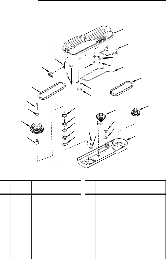
Repair Parts
Parts List for RIDGID 15" Drill Press
Model No. DP15501
Figure 1
Always order by Part Number - Not by Key Number
* Standard hardware item - may be purchased locally.
1
4
6
11
15
19
17
18
2
4
4
4
7
21
22
16 10
13
5
3
20
8
9
910
13
14
14
12
Key
No. Part No. Description
1
2
3
4
5
6
7
8
9
10
829775
828814
828812
828932
828813
828811
816439-4
828919
817358-1
820241-5
Guard Upper
Link - Rear
Clamp - Rear Link
* Screw Pan Hd
M5.5 x 1.8-12
Link - Front
Clamp - Front Link
Belt Poly V 27"
Pulley Asm - Idler
* Screw Rd Hd Wash
M6 x 1.0
* Lockwasher Ext M6
Key
No. Part No. Description
11
12
13
14
15
16
17
18
19
20
21
22
828818
828816
817537
817530
817536
821734
828849
821742
829688
816439-5
828820
828821
Pulley Asm - Motor
Guard Lower
Ring Retaining
Bearing Ball 20 mm
Spacer
Insert Pulley
Pulley Spindle
Nut Pulley
Cap Spindle
Belt Poly V 25"
Latch
Spring Latch
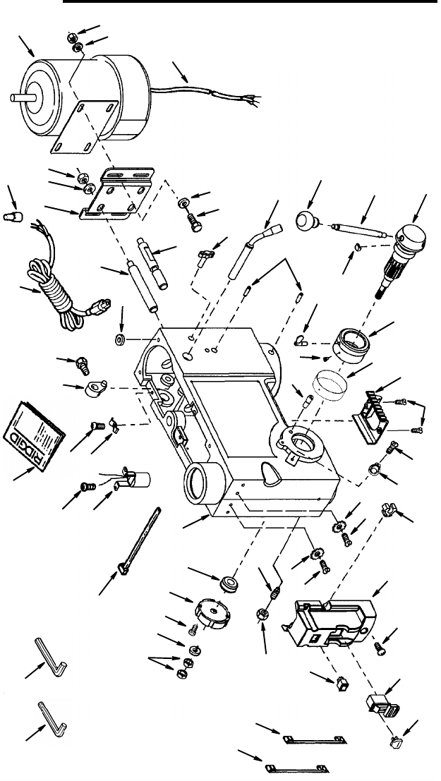
36
Repair Parts
Parts List for RIDGID 15" Drill Press
Model No. DP15501
Figure 2
1
23
4
5
678
9
10
11
12
13
14 15
16
17
18
19
20
21
22
23
24
26
27
28
29
30 31
32
33
37
39
40
4243
44
47
48
3
20
25
25
35
36
41
43
46 45
49
50
51
52 53
54
55 56
34
35
38

37
Repair Parts
Parts List for RIDGID 15" Drill Press
Model No. DP15501
Figure 2
Always order by Part Number -- Not by Key Number
* Standard hardware item - may be purchased locally.
• Any attempt to repair this motor may create a hazard unless repair is done by a qual-
ified service technician.
Repair service is available at your nearest Authorized Service Center.
Key
No. Part No. Description
1
2
3
4
5
6
7
8
9
10
11
12
13
14
15
16
17
18
19
20
21
22
23
24
25
26
27
28
29
828929
820381-2
821063-2
828940
824026-7
817336-1
820383-8
820236-9
817495
817516
817330
828941
SP6490
817317
820381-4
817320
817494
821750
828904
826445
826441
817300
829590
828876
816743-4
826057
828880
821738-3
828917
• Motor
* Screw Hex Hd.
M8 x 1.25-20
* Washer M8 x 16 x 1.6
Cord Motor
* Nut Hex M8 x 1.25
Mount Motor
* Lockwasher 12mm
* Nut Hex M12 x 1.75
Support Motor Bracket
Support Motor Bracket
Connector Wire
Cord w/Plug
Operator’s Manual
Lever Adjusting
* Screw Hex Hd.
M8 x 1.25-16
Knob Motor Adjusting
Handle Belt Tension
Screw Hex Soc. Set
M10 x 1.5-12
Hub Asm.
Rod
Knob
Guide Scale
Ring Depth Stop
Scale Depth
* Screw Pan Cr
M4 x 0.7 x 8
Pointer
Spring Asm.
* Nut Hex M12 x 1.5-8
Pin Stop
Key
No. Part No. Description
30
31
32
33
34
35
36
37
38
39
40
41
42
43
44
45
46
47
48
49
50
51
52
53
54
55
56
828877
828963
820240-6
829595
820244
817343
828928
820378
820294
829689
829826
810506-3
829803
820241-4
828921
820240
829787
826122
829597
829597-1
828923
829690
820236-8
817308
820240-3
813317-6
813317-8
Holder Key Chuck
Lens Assembly
* Screw Pan Hd.
M5 x 0.8-12
Socket Bulb Asm.
* Screw Pan Hd.
M6 x 1.0-12
Lock Depth Screw
Bearing Pinion Shaft
Screw Soc Cap
M4 x 0.7-10
Washer Foam
Clamp Cord
Head Asm.
Tie Wire
Screw Hex Hd. Gnd.
M5 x 0.8
Lockwasher Ext. M5
Box Switch Asm.
* Screw Pan Hd.
M5 x 0.8-16
Switch Locking
Key Switch
Lead 3" Black
Lead 3" White
Switch Rocker
Washer 12mm ID Plain
* Nut Hex M10 x 1.5
Screw Sl. Set Fl Pt
* Screw Pan Hd
M5 x 0.8-6
Wrench Hex “L” 3mm
Wrench Hex “L” 5mm
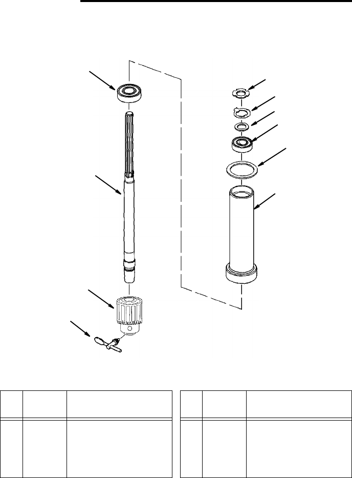
38
Repair Parts
Parts List for RIDGID 15" Drill Press
Model No. DP15501
Figure 3
Always order by Part Number - Not by Key Number
1
2
3
4
5
6
7
8
9
10
Key
No. Part No. Description
1
2
3
4
5
817309
817310
817311
813480
817535
Lock Nut M17 x 1.0
Ring Locking
Washer
Bearing Ball 17mm
Gasket Quill
Key
No. Part No. Description
6
7
8
9
10
828875
817339
817340
828908
817529
Tube Quill
Key Chuck
Chuck
Spindle
Bearing Ball
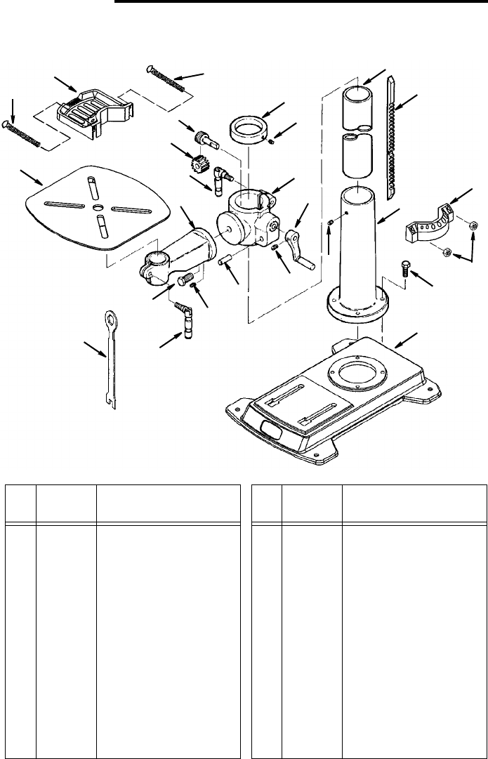
39
Repair Parts Parts List for RDIGID 15" Drill Press
Model No. DP15501
Figure 4
* Standard hardware item - may be purchased locally.
1
2
3
6
7
8
10
11
4
5
2
2
18
15
17
16
14
13
12
19
20
21
9
20
22
23
Key
No. Part No. Description
1
2
3
4
5
6
7
8
9
10
11
817478
820245
821861-2
826439
821880
828927
821881-1
828870
813164-6
821754
828961
Collar Rack
* Screw Hex Soc. Set
M6 x 1.0-10
Support Table
w/Indicator
Crank (Includes Set
Screw)
Tube Column
Rack
Support Column
Tray, Back
Nut Hex M5
* Screw Hex Hd.
M10 x 1.5-40
Base
Key
No. Part No. Description
12
13
14
15
16
17
18
19
20
21
22
23
821750
817288
817290-3
821732
817777-3
817294-2
817350
817349
10251002
828871
828903
826438
* Screw Hex Soc. Set
M10 x 1.5-12
Pin Gear
Clamp Table
Screw Hex Hd.
M16 x 2.0-35
Arm Table w/Scale
Clamp Column
Gear Helical
Worm Elevation
* Screw Pan Hd Cr
M5 x 0.8-60
Tray, Front
Tab l e
Wrench Hex 24mm

QUESTIONS OR COMMENTS?
CALL 1-866-539-1710
www.ridgid.com
Please have your Model Number and Serial
Number on hand when calling.
RIDGID¨ HAND HELD AND STATIONARY POWER TOOL
LIMITED THREE YEAR WARRANTY AND 90-DAY
SATISFACTION GUARANTEE POLICY
This product is manufactured by One World Technologies, Inc.,
under a trademark license from Ridgid, Inc. All warranty com-
munications should be directed to One World Technologies,
Inc., attn: RIDGID handheld and stationary power tool technical
service at (toll free) 1-866-539-1710.
90-DAY SATISFACTION GUARANTEE POLICY
During the first 90 days after the date of purchase, if you are
dissatisfied with the performance of this RIDGID tool for any
reason you may return the tool to the dealer from which it was
purchased for a full refund or exchange. To receive a replace-
ment tool you must present proof of purchase and return all
original equipment packaged with the original product. The
replacement tool will be covered by the limited warranty for the
balance of the three year warranty period.
WHAT IS COVERED UNDER THE LIMITED THREE YEAR
WARRANTY
This warranty covers all defects in workmanship or materials in
this RIDGID tool for the three year period from the date of pur-
chase. This warranty is specific to this tool. Warranties for other
RIDGID products may vary.
HOW TO OBTAIN SERVICE
To obtain service for this RIDGID tool you must return it, freight
prepaid, to an authorized RIDGID service center for hand held
and stationary power tools. You may obtain the location of the
authorized service center nearest you by calling (toll free) 1-
866-539-1710 or by logging on to the RIDGID website at
www.ridgid.com. When requesting warranty service, you must
present the proof of purchase documentation, which includes a
date of purchase. The authorized service center will repair any
faulty workmanship, and either repair or replace any defective
part, at our option at no charge to you.
WHAT IS NOT COVERED
This warranty applies only to the original purchaser at retail and
may not be transferred. This warranty only covers defects aris-
ing under normal usage and does not cover any malfunction,
failure or defect resulting from misuse, abuse, neglect, alter-
ation, modification or repair by other than an authorized service
center for RIDGID branded hand held and stationary power
tools. RIDGID, INC. AND ONE WORLD TECHNOLOGIES,
INC. MAKE NO WARRANTIES, REPRESENTATIONS OR
PROMISES AS TO THE QUALITY OR PERFORMANCE OF
ITS POWER TOOLS OTHER THAN THOSE SPECIFICALLY
STATED IN THIS WARRANTY.
ADDITIONAL LIMITATIONS
To the extent permitted by applicable law, all implied warranties,
including warranties of MERCHANTABILITY or FITNESS FOR
A PARTICULAR PURPOSE, are disclaimed. Any implied war-
ranties, including warranties of merchantability or fitness for a
particular purpose, that cannot be disclaimed under state law
are limited to three years from the date of purchase. One World
Technologies, Inc. is not responsible for direct, indirect, inciden-
tal or consequential damages. Some states do not allow limita-
tions on how long an implied warranty lasts and/or do not allow
the exclusion or limitation of incidental or consequential dam-
ages, so the above limitations may not apply to you. This war-
ranty gives you specific legal rights, and you may also have
other rights which vary from state to state.
Part No. SP6490 Form No. SP6490 Printed in China 8/03
Stock No. DP1550 Model No. DP15501
Serial No. ________ Model and serial numbers
may be found at the left side of the head. You
should record serial number in a safe place for
future use.
One World Technologies, Inc.
Hwy. 8
Pickens, SC 29671
