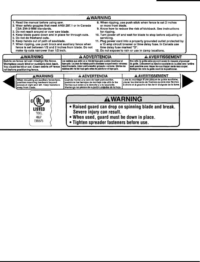
Ridgid Table Saw Users Manual
Table Saw to the manual 2abf0c18-e3bd-464b-a222-13259d1354f8
2015-02-04
: Ridgid Ridgid-Table-Saw-Users-Manual-387884 ridgid-table-saw-users-manual-387884 ridgid pdf
Open the PDF directly: View PDF ![]() .
.
Page Count: 68


2
Table of Contents
Section Page
Table of Contents ........................................ 2
Safety Instructions For Table Saw ............. 3
Safety Signal Words .................................. 3
Before Using The Saw ............................... 3
When Installing Or Moving The Saw ............ 4
Before Each Use ........................................... 4
To Reduce the Risk of Injury From Jams, Slips
Or Thrown Pieces (Kickbacks Or
Throwbacks) ............................................. 5
Plan Ahead To Protect Your Eyes, Hands,
Face and Ears ............................................ 6
Whenever Sawblade Is Spinning ................. 7
Additional Safety Instructions For: Rip Cuts.. 8
Additional Safety Instructions For: Crosscuts 9
Glossary of Terms for Woodworking ........ 9
Motor Specifications and Electrical
Requirements ........................................ 11
Power Supply and Motor Specifications ..11
General Electrical Connections ...............11
Motor Specifications and Electrical
Requirements ........................................ 12
Thermal Overload Protector .................... 13
Wire Sizes ................................................ 13
Unpacking and Checking Contents ......... 14
Unpacking .................................................14
List of Loose Parts .................................... 14
Getting to Know Your Table Saw ............. 15
Alignment ................................................... 20
Tools Needed ........................................... 20
Remove Foam Motor Support .................. 20
Checking Table Insert ............................... 20
Checking Heeling Adjustment or Parallelism
of Sawblade to Miter Gauge Groove ...... 21
Checking Blade Tilt, or Squareness of Blade
to Table .................................................. 23
To Check For Squareness, 90° Position ...23
Adjusting Rip Fence Guide Bars ...............25
Aligning Sliding Table Extension .............. 26
Rip Fence Alignment Adjustment ............. 26
Rip Fence Lock Lever Adjustment ............ 27
Adjusting Rip Indicator .............................. 27
Checking Sliding Table Extension ............ 28
Installing Blade Guard ..............................28
Aligning Blade Guard ................................ 29
Removing and Installing Sawblade ........... 30
Miter Gauge Alignment ............................. 31
Adjusting Bevel Lock ................................ 32
Mounting Your Saw ................................... 33
Mounting Table Saw to Workbench
or Legset ................................................ 33
Workbench Mounting Using Hardware .....33
Table Saw Mounting Procedures .............. 33
Mounting Table Saw to RIDGID Universal
Power Tool Legset #AC9910 .................. 34
Section Page
Workbench Mounting Using "C" Clamps ..34
Supporting Table Saw with Sawhorses .... 34
Safety Instructions for Basic Saw
Operations.............................................. 35
Before Each Use ....................................... 35
To Reduce the Risk of Injury From Jams, Slips
Or Thrown Pieces (Kickbacks Or
Throwbacks) ........................................... 35
Plan Ahead To Protect Your Eyes, Hands,
Face and Ears .......................................... 36
Whenever Sawblade Is Spinning ................ 37
Work Feed Devices ................................... 38
Attaching Wood Face Board ..................... 39
Push Block ................................................ 39
Work Feed Devices ................................... 40
Auxiliary Fence ......................................... 40
Fence Facing ............................................41
Basic Saw Operations ............................... 42
Using the Miter Gauge .............................. 42
Additional Safety Instructions for
Crosscutting ........................................... 42
Crosscutting .............................................. 42
Repetitive Crosscutting ............................. 43
Miter Crosscutting ..................................... 44
Bevel Crosscutting .................................... 44
Compound Crosscutting ........................... 44
Using the Rip Fence ................................. 45
Additional Safety Instructions for Rip Cuts 45
Ripping ...................................................... 46
Bevel Ripping Narrow Work ...................... 47
Using Featherboards for Thru Sawing ...... 48
Using Featherboards for
Non-Thru Sawing.................................... 49
Resawing .................................................. 50
Using Carbide Tipped Blades ................... 50
Dadoing ....................................................51
Rabbeting ................................................. 52
Ploughing and Molding ............................. 52
Molding ..................................................... 53
Maintaining Your Table Saw ..................... 54
Maintenance ............................................. 54
Adjusting Nylon Set Screw ....................... 54
Replacing Carbon Brushes ....................... 55
Lubrication ................................................ 55
RIDGID Recommends the Following
Accessories .......................................... 55
Troubleshooting ........................................56
General ..................................................... 56
Motor ......................................................... 57
Repair Parts ............................................... 58
Notes .......................................................... 65

3
Safety Instructions For Table Saw
Safety is a combination of common sense, staying alert and knowing how
your table saw works. Read this manual to understand this table saw.
Safety Signal Words
DANGER: means if the safety infor-
mation is not followed someone will
be seriously injured or killed.
WARNING: means if the safety infor-
mation is not followed someone
could be seriously injured or killed.
CAUTION: means if the safety infor-
mation is not followed someone may
be injured.
Before Using The Saw
WARNING: Some dust created by
power sanding, sawing, grinding,
drilling, and other construction
activities contains chemicals
known (to the State of California)
to cause cancer, birth defects or
other reproductive harm. Some
examples of these chemicals are:
Lead from lead-based paints
• Crystalline silica from bricks
and cement and other masonry
products, and
• Arsenic and chromium from
chemically-treated lumber.
Your risk from these exposures
varies, depending on how often
you do this type of work. To
reduce your exposure to these
chemicals: work in a well venti-
lated area, and work with
approved safety equipment,
such as those dust masks that
are specially designed to filter
out microscopic particles.
WARNING: To reduce the risk of
mistakes that could cause seri-
ous, permanent injury, do not
plug the table saw in until the fol-
lowing steps have been satisfac-
torily completed.
• Completely align and align saw
(See “Alignment” section).
• Learn the use and function of the
ON-OFF switch, blade guard,
spreader, anti-kickback device,
miter gauge, rip fence, table insert,
blade elevation and blade bevel lock
controls (See “Getting to Know Your
Table Saw” section).
• Review and understand all safety
instructions and operating proce-
dures in this manual.
• Review the maintenance methods
for this saw (See “Maintaining Your
Table Saw” section)).
4
Safety Instructions For Table Saw (continued)
• Find and read all the warning labels found on the saw (shown below).
When Installing Or Moving The Saw
Reduce the Risk of Dangerous
Environment.
• Use the saw in a dry, indoor place
protected from rain.
• Keep work area well lighted.
• Use recommended accessories.
Consult the owner’s manual for rec-
ommended accessories. The use of
improper accessories may cause
risk of injury to persons.
To reduce the risk of injury from
unexpected saw movement.
• Bolt or clamp the saw to firm level
surface where there is plenty of
room to handle and properly support
the workpiece (See “Assembly-
Mounting Your Saw” section).
• Support the saw so the table is level
and the saw does not rock.
• Put the saw where neither operator
nor bystanders must stand in line
with the sawblade.
• To reduce the risk of injury from
electrical shock, make sure your fin-
gers do not touch the plug’s metal
prongs when plugging in or unplug-
ging the saw.
•Never Stand On Tool. Serious
injury could occur if the tool tips or
you accidentally hit the cutting tool.
Do not store anything above or near
the tool where anyone might stand
on the tool to reach them.
Before Each Use
Inspect your saw.
• To reduce the risk of injury from
accidental starting, turn the switch
off, unplug the saw, and remove the
switch key before raising or remov-
ing the guard, changing the cutting
tool, changing the setup, or adjust-
ing anything. Make sure switch is in
OFF position before plugging in.
• Check for alignment of moving
parts, binding of moving parts,
breakage of parts, saw stability, and
any other conditions that may affect
the way the saw works.

5
• If any part is missing, bent or broken
in any way, or any electrical part
does not work properly, turn the saw
off and unplug the saw.
• Replace damaged or missing parts
before using the saw again.
• Use the sawblade guard, spreader
and anti-kickback pawls for any
thru-sawing (whenever the blade
comes through the top of the work-
piece). Make sure the anti-kickback
pawls work properly. Make sure the
spreader is in line with sawblade
(See “Assembly-Aligning Blade
Guard” section).
• Remove adjusting keys and
wrenches. Form a habit of checking
for and removing keys and adjusting
wrenches from table top before turn-
ing saw on.
• Make sure all clamps and locks are
tight and no parts have excessive
play.
To Reduce the Risk of Injury From Jams, Slips Or Thrown Pieces
(Kickbacks Or Throwbacks)
Inspect Your Blade.
• Choose the right blade or cutting
accessory for the material and the
type of cutting you plan to do.
• Use The Right Tool. Don’t force tool
or attachment to do a job it was not
designed for.
• Never use grinding wheels, abrasive
cutoff wheels, friction wheels (metal
cutting blades) wire wheels or buff-
ing wheels. They can fly apart
explosively.
• Cut only wood, wood like or plastic
materials. Do not cut metal.
• Choose and inspect your cutting
tool carefully:
- To reduce the risk of cutting tool
failure and thrown shrapnel (bro-
ken pieces of blade), use only 10”
or smaller blades or other cutting
tools marked for speeds of 5000
rpm or higher.
- Always use unbroken, balanced
blades designed to fit this saw’s 5/8
inch arbor.
- When thru-sawing (making cuts
where the blade comes through
the workpiece top), always use a
10 inch diameter blade. This keeps
the spreader closest to the blade.
- Do not over tighten arbor nut. Use
arbor wrenches to “snug” it
securely.
- Use only sharp blades with prop-
erly set teeth. Consult a profes-
sional blade sharpener when in
doubt.
- Keep blades clean of gum and
resin.
- Never use the saw without the
proper blade insert.
Inspect your work area
• Keep work area clean.
• Cluttered areas and benches invite
accidents. Floor must not be slip-
pery from wax or sawdust.
• To reduce the risk of burns or other
fire damage, never use the saw
near flammable liquids, vapors or
gases.
• To reduce the risk of injury, don’t do
layout, assembly, or setup work on
the table while blade is spinning. It
could cut or throw anything hitting
the blade.

6
Safety Instructions For Table Saws (continued)
Plan your work
• Use the right tool. Don’t force tool or
attachment to do a job it was not
designed for.
Inspect your workpiece.
• Make sure there are no nails or for-
eign objects in the part of the work-
piece to be cut.
• When cutting irregularly shaped
workpieces, plan your work so it will
not slip and pinch the blade:
- A piece of molding for example,
must lie flat or be held by a fixture
or jig that will not let it twist, rock or
slip while being cut. Use jigs or fix-
tures where needed to prevent
workpiece from shifting.
• Use a different, better suited type of
tool for work that can’t be made sta-
ble.
Plan your cut
• To reduce the risk of kickbacks and
throwbacks - when a part or all of
the workpiece binds on the blade
and is thrown violently back toward
the front of the saw:
• Never cut Freehand. Always use
either a rip fence, miter gauge or fix-
ture to position and guide the work,
so it won’t twist or bind on the blade
and kick back.
• Make sure there’s no debris
between the workpiece and its sup-
ports.
• Use extra caution with large, very
small or awkward workpieces.
• Use extra supports (tables, saw
horses, blocks, etc.) for any work-
pieces large enough to tip when not
held down to the table top. Never
use another person as a substitute
for a table extension, or as addi-
tional support for a workpiece that is
longer or wider than the basic saw
table, or to help feed, support or pull
the workpiece.
• Never confine the piece being cut
off, that is, the piece not against the
rip fence, miter gauge or fixture.
Never hold it, clamp it, touch it, or
use length stops against it. It must
be free to move. If confined, it could
get wedged against the blade and
cause a kickback or throwback.
• Never cut more than one workpiece
at a time.
• Never turn your table saw “ON”
before clearing everything except
the workpiece and related support
devices off the table.
Plan Ahead To Protect Your Eyes, Hands, Face and Ears
Dress for safety
• Do not wear loose clothing, gloves,
neckties or jewelry (rings, wrist
watches). They can get caught and
draw you into moving parts.
• Wear nonslip footwear.
• Tie back long hair.
• Roll long sleeves above the elbow.
• Noise levels vary widely. To reduce
the risk of possible hearing damage,
wear ear plugs or muffs when using
table saw for hours at a time.
• Any power saw can throw foreign
objects into the eyes. This can result
in permanent eye damage. Always
wear safety goggles, not glasses
complying with ANSI Z87.1 (or in
Canada CSA Z94.3-99) shown on
package. Everyday eyeglasses
have only impact resistant lenses.
They are not safety glasses. Safety
goggles are available at many local
7
retail stores. Glasses or goggles not
in compliance with ANSI or CSA
could seriously hurt you when they
break.
• For dusty operations, wear a dust
mask along with safety goggles.
Plan the way you will push the
workpiece through.
•Never pull the workpiece through.
Start and finish the cut from the front
of the table saw.
•Never put your fingers or hands
in the path of the sawblade or other
cutting tool.
•Never reach in back of the cutting
tool with either hand to hold down
workpiece, support the workpiece,
remove wood scraps, or for any
other reason.
• Reduce the risk of hand positions
where a sudden slip could cause fin-
gers or hand to move into a saw-
blade or other cutting tool.
• Don’t overreach. Always keep good
footing and balance.
• Push the workpiece against the
rotation of the blade, never feed
material into the cutting tool from the
rear of the saw.
• Always push the workpiece all the
way past the sawblade.
• As much as possible, keep your
face and body to one side of the
sawblade, out of line with a possible
kickback or throwback.
• Set the cutting tool as low as possi-
ble for the cut you’re planning.
Reduce the Risk of Accidental
Starting
• Make sure switch is “OFF” before
plugging saw into a power outlet.
Whenever Sawblade Is Spinning
WARNING: Don't allow familiarity
(gained from frequent use of
your table saw) to cause a care-
less mistake. Always remember
that a careless fraction of a sec-
ond is enough to cause a severe
injury.
• Before actually cutting with the saw,
watch it while it runs for a short
while. If it makes an unfamiliar noise
or vibrates a lot, stop immediately.
Turn the saw off. Unplug the saw.
Do not restart until finding and cor-
recting the problem.
• Make sure the top of the arbor or
cutting tool turns toward the front of
the saw.
Keep Children Away.
• Keep all visitors a safe distance
from the table saw.
• Make sure bystanders are clear of
the table saw and workpiece.
Don’t Force Tool.
• Let the blade reach full speed
before cutting.
• It will do the job better and safer at
its designed rate.
• Feed the workpiece into the saw
only fast enough to let the blade cut
without bogging down or binding.
Before freeing jammed material.
• Turn switch “OFF”.
• Wait for all moving parts to stop.
• Unplug the saw.
• Check blade, spreader and fence
for proper alignment before starting
again.
8
Safety Instructions For Table Saws (continued)
To reduce the risk of throwback of
cut off pieces.
• Use the guard assembly.
To remove loose pieces beneath or
trapped inside the guard.
• Turn saw “OFF”.
• Remove switch key.
• Wait for blade to stop before lifting
the guard.
Before Leaving The Saw.
• Turn the saw off.
• Wait for blade to stop spinning.
• Unplug the saw.
• Make workshop child-proof. Lock
the shop. Disconnect master
switches. Remove the yellow switch
key. Store it away from children and
others not qualified to use the tool.
Additional Safety Instructions For:
Rip Type Cuts.
• Never use the miter gauge when rip-
ping. Store the miter gauge in the
area provided in the base.
• Use a push stick whenever the
fence is 2 inches or more from the
blade.
• When thru-sawing, use an auxiliary
fence and push block whenever the
fence must be between 1/2 and 2
inches from the blade.
• Never thru-saw rip cuts narrower
than 1/2 inch. (See “Basic Saw
Operations-Ripping and Bevel Rip-
ping” sections.)
• Never rip anything shorter than 10”
long.
• When using a push stick or push
block, the trailing end of the board
must be square. A push stick or
block against an uneven end could
slip off or push the work away from
the fence.
• A Featherboard can help guide the
workpiece. (see ”Basic Saw Opera-
tion-Using Featherboards for Thru-
Sawing.” section)
• Always use featherboards for any
non thru rip type cuts. (See “Basic
Saw Operations - Using Feather-
boards for Non-Thru Sawing” sec-
tion).
Before Starting.
• To reduce the risk of kickbacks and
slips into the blade, make sure the
rip fence is parallel to the sawblade.
• Before thru-sawing, check the anti-
kickback pawls. The pawls must
stop a kickback once it has started.
Replace or sharpen anti-kickback
pawls when points become dull.
(See “Maintaining Your Table Saw -
Anti-Kickback Pawls” section.)
• Plastic and composition (like hard-
board) materials may be cut on your
saw. However, since these are usu-
ally quite hard and slippery, the anti-
kickback pawls may not stop a kick-
back. Therefore, be especially care-
ful in your setup and cutting
procedures.
While Thru-sawing.
• To reduce the risk of kickbacks and
slips into the blade, always push for-
ward on the section of the work-
piece between the sawblade and
the rip fence. Never push forward on
the piece being cut off or directly in
line with the blade.
Featherboard
See “Work Feed Devices” section for
Material and Dimensions

9
Additional Safety Instructions For:
Crosscut Type Cuts.
• Never use the rip fence when cross-
cutting.
• An auxiliary wood facing attached to
the miter gauge can help prevent
workpiece twisting and throwbacks.
Attach it to the slots provided. Make
the facing long enough and big
enough to support your work. Make
sure, however, it will not interfere
with the sawblade guard.
Before Starting
• Use jigs or fixtures to help hold any
piece too small to extend across the
full length of the miter gauge face
during the cut. This lets you properly
hold the miter gauge and workpiece
and helps keep your hands away
from the blade.
While Cutting
• To reduce the risk of blade contact,
always hold the miter gauge as
shown in “Basic Saw Operations -
Using The Miter Gauge”.
Glossary of Terms for Woodworking
Anti-Kickback Pawls
Device which, when properly maintained,
is designed to stop the workpiece from
being thrown towards the front of the saw
at the operator during ripping operation.
Arbor
The shaft on which a cutting tool is
mounted.
Bevel Cut
An angle cutting operation made through
the face of the workpiece.
Compound Cut
A simultaneous bevel and miter crosscut-
ting operation.
Crosscut
A cutting operation made across the width
of the workpiece.
Dado
A non thru cut which produces a square
sided notch or trough in the workpiece.
Featherboard
A device which can help guide work-
pieces during rip type operation.
Freehand
Performing a cut without the use of fence
(guide), miter gauge, fixture, hold down or
other proper device to prevent the work-
piece from twisting during the cutting
operation. Twisting of the workpiece can
cause it to be thrown.
Gum
A sticky, sap based residue from wood
products.
Heel
Misalignment of the sawblade such that
the blade is not parallel to the miter gauge
groove.
Kerf
The amount of material removed by the
blade in a through cut or the slot produced
by the blade in a nonthrough or partial cut.
Kickback
An uncontrolled grabbing and throwing of
the workpiece back toward the front of the
saw.
Leading End
The end of the workpiece which, during a
rip type operation, is pushed into the cut-
ting tool first.
Miter Cut
An angle cutting operation made across
the width of the workpiece.
Molding
A non through cut which produces a spe-
cial shape in the workpiece used for join-
ing or decoration.
Ploughing
Grooving with the grain the length of the
workpiece, using the fence. (A type of
non-through cut.)
10
Glossary of Terms for Woodworking (continued)
Push Stick
A device used to feed the workpiece
through the saw during narrow ripping
type operations which helps keep the
operator’s hands well away from the
blade.
Push Block
A device used for ripping type operations
too narrow to allow use of a push stick.
Rabbet
A notch in the edge of a workpiece. (A
type of non-through cut)
Resin
A sticky, sap based substance that has
hardened.
Revolutions Per Minute (RPM)
The number of turns completed by a spin-
ning object in one minute.
Rip Cut
A cutting operation along the length of the
workpiece.
Sawblade Path
The area of the workpiece or table top
directly in line with either the travel of the
blade or the part of the workpiece which
will be, or has been, cut by the blade.
Set
The distance that the tip of the sawblade
tooth is bent (or set) outward from the
face of the blade.
Throw-Back
Throwing of pieces in a manner similar to
a kickback.
Thru-Sawing
Any cutting operation where the blade
extends completely through the thickness
of the workpiece.
Trailing End
The workpiece end last cut by the blade in
a ripping operation.
Workpiece
The item on which the cutting operation is
being performed. The surfaces of a work-
piece are commonly referred to as faces,
ends, and edges.
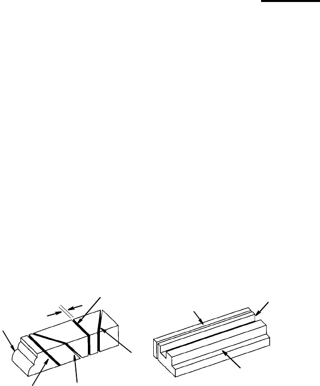
Molding Kerf
Cross Cut
Miter Cut
Compound
Bevel Cut
Rip Cut Dado or
Rabbet
Ploughing
Cut

11
Motor Specifications and Electrical Requirements
Power Supply and Motor
Specifications
WARNING: To reduce the risk of
electrical hazards, fire hazards or
damage to the tool, use proper
circuit protection. Your tool is
wired at the factory for operation
using the voltage shown. Con-
nect tool to a power line with the
appropriate voltage and a 15-
amp branch circuit. Use a 15-
amp time delay type fuse or cir-
cuit breaker. To reduce the risk of
shock or fire, if power cord is
worn or cut, or damaged in any
way, have it replaced immedi-
ately.
The A-C motor used on this tool is a uni-
versal non-reversible type, having the fol-
lowing specifications.
General Electrical Connections
DANGER: To reduce the risk of
electrocution:
1. Use only identical replace-
ment parts when servicing.
Servicing should be per-
formed by a qualified service
technician.
2. Do not use in rain or where
floor is wet.
This tool is intended for
indoor residential use only.
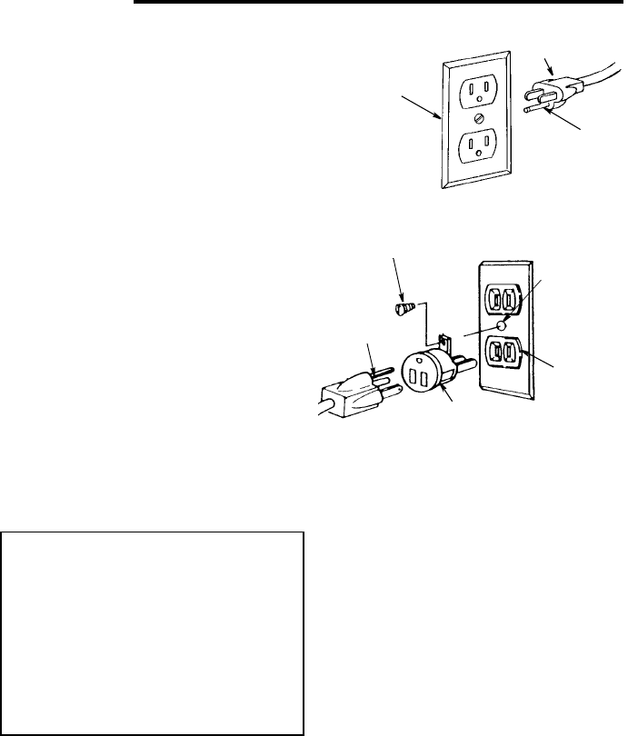
WARNING: Do not permit fingers
to touch the terminals of plug
when installing or removing the
plug to or from the outlet.
110-120 Volt, 60 Hz. Tool Information
The plug supplied on your tool may not fit
into the outlet you are planning to use.
Your local electrical code may require
slightly different power cord plug connec-
tions. If these differences exist refer to
and make the proper adjustments per
your local code before your tool is
plugged in and turned on.
In the event of a malfunction or break-
down, grounding provides a path of least
resistance for electric current to reduce
the risk of electric shock. This tool is
equipped with an electric cord having an
equipment-grounding conductor and a
grounding plug, as shown. The plug must
be plugged into a matching outlet that is
properly installed and grounded in accor-
dance with all local codes and ordi-
nances.
Do not modify the plug provided. If it will
not fit the outlet, have the proper outlet
installed by a qualified electrician.
Voltage 120
Amperes 15
Hertz (Cycles) 60
Phase Single
RPM 4000
Rotation of Shaft Counterclockwise
(Blade End)
12
Motor Specifications and Electrical Requirements
(continued)
A temporary adapter may be used to con-
nect this plug to a 2-prong outlet as
shown if a properly grounded three prong
outlet is not available. This temporary
adapter should be used only until a prop-
erly grounded three prong outlet can be
installed by a qualified electrician. The
green colored rigid ear, lug or the like,
extending from the adapter must be con-
nected to a permanent ground such as a
properly grounded outlet box.
Improper connection of the equipment-
grounding conductor can result in a risk of
electric shock. The conductor with insula-
tion having an outer surface that is green
with or without yellow stripes is the equip-
ment-grounding conductor. If repair or
replacement of the electric cord or plug is
necessary, do not connect the equipment-
grounding conductor to a live terminal.
If the grounding instructions are not com-
pletely understood, or if you are in doubt
as to whether the tool is properly
grounded check with a qualified electri-
cian or service personnel.
WARNING: If not properly
grounded, this tool can cause an
electrical shock, particularly
when used in damp locations, in
proximity to plumbing, or out of
doors. If an electrical shock
occurs there is the potential of a
secondary hazard, such as your
hands contacting the sawblade.
NOTE: The adapter illustrated is for use
only if you already have a properly
grounded 2-prong outlet.
NOTE: In Canada the use of a temporary
adapter is not permitted by the Canadian
Electrical Code.
3-Prong
Adapter
2-Prong
Outlet
Make sure this
Is Connected
Ground
Plug
to a Known
Grounding Lug
Properly
Grounded 3-Prong Plug
Grounding
Prong
3-Prong Outlet
13
CAUTION: To reduce the risk of
motor damage, this motor
should be blown out or vacu-
umed frequently to prevent saw-
dust buildup which will interfere
with normal motor ventilation.
1. Frequent “blowing” of fuses or tripping
of circuit breakers may result if:
a. Motor is overloaded - Overloading
can occur if you feed too rapidly or if
saw blade is dull or misaligned.
b. Motor circuit is fused differently from
recommendations - Always follow
instructions for the proper fuse/
breaker. Do not use a fuse/breaker of
greater capacity without consulting a
qualified electrician.
c. Low voltage - Although the motor is
designed for operation on the voltage
and frequency specified on motor
nameplate, normal loads will be han-
dled safely on voltage not more than
10% above or below the nameplate
voltage. Heavy loads, however,
require that voltage at motor termi-
nals equals the voltage specified on
nameplate.
2. Most motor troubles may be traced to
loose or incorrect connections, overload-
ing, reduced input voltage (such as
small size wire in the supply circuit or
extension cord) or to overly long supply
circuit wire or extension cord. Always
check the connections, the load and the
supply circuit whenever motor fails to
perform satisfactorily. Check wire sizes
and length with the Wire Size Chart
below.
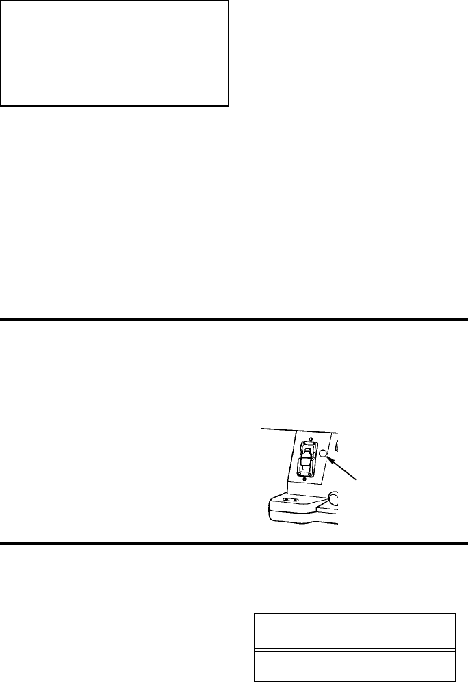
Thermal Overload Protector
This saw is equipped with a thermal over-
load device which will automatically “trip”
and cause the saw to shut down if the
motor is overheating due to continuous
heavy cutting or stalling.
The overload device can only be reset
manually by the user after the motor has
been allowed to adequately cool. Allow
15-30 minutes.
Should the overload protector “trip”:
1. Turn switch off and remove key.
2. Remove workpiece.
3. Wait 15-30 minutes.
4. Push in on the reset button.
5. If motor has cooled, button will remain
in.
Wire Sizes
NOTE: Make sure the proper extension
cord is used and is in good condition.
The use of any extension cord will cause
some loss of power. To keep this to a min-
imum and to prevent overheating and
motor burn-out, use the table shown to
determine the minimum wire size (A.W.G.)
extension cord.
Use only 3-wire extension cords which have
3-prong grounding type plugs and 3-prong
receptacles which accept the tool’s plug.
Thermal Overload
Device
Extension
Cord Length Gauge
(A.W.G.)
0-25 Ft.
26-50 Ft.
14
12
14
Unpacking and Checking Contents
Unpacking
Separate saw and all parts from packing
materials and check each one with the
illustration and the “List of Loose Parts” to
make certain all items are accounted for,
before discarding any packing material.
Call 1-866-539-1710 or E-mail us at
info@ridgidwoodworking.com if any parts
are damaged or missing.
WARNING: If any parts are miss-
ing, do not attempt to use the
table saw, plug in the power cord
or turn the switch on until the
missing parts are obtained and
are installed correctly.
WARNING: The saw is heavy. To
reduce the risk of back injury,
hold the saw close to your body.
Bend your knees so you can lift
with your legs, not your back.
Use hand holds provided.
WARNING: For your own safety,
never connect plug to power
source outlet until all assembly
steps are complete, and you
have read and understand the
safety and operating instruc-
tions.
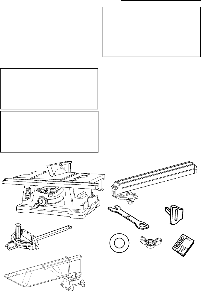
List of Loose Parts
Item Part Name Qty.
A Table Saw Assembly ....................... 1
B Miter Gauge..................................... 1
C Blade Guard and Spreader.............. 1
D Rip Fence........................................ 1
E Arbor Wrenches .............................. 2
Item Part Name Qty.
F Safety Key....................................... 1
G Blade Storage Washers................... 2
H Blade Storage Wingnut.................... 1
J Operators Manual............................ 1
A
B
F
GH
E
J
C
D
15
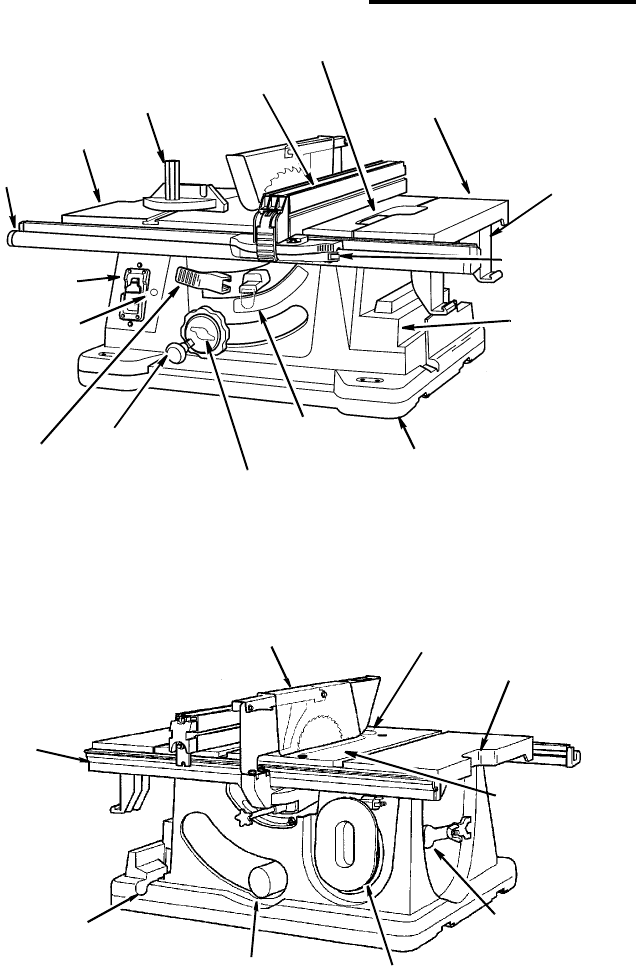
Getting to Know Your Table Saw
1 Rip Fence 4 Sliding Table
6 MIter Gauge
7 Two-Piece
8 Blade Tilt
12 On-Off
9 Elevation/Bevel
11 Blade Tilt
Lock Lever
5 Rip Fence
Storage
Handwheel Scale
Base
Storage
Extension
3 Table Extension
Lock Lever
13 Thermal
2 MicroAdjust
Rip Fence
10 Blade Elevation
Lock Knob
Switch
Overload
Device
22 Sawdust
Ejection Port
20 Wrench & Blade
Storage
23 Blade Guard Storage
for Non-thru Cuts
18 Carry
Handles
21 Cord Wrap
17 Ind-I-Cut
Rear Fence
Rail
19 Table Insert
and Transportation Only
16 Blade Guard
Front Fence
Rail
15 Miter Gauge
14 Table

16
Getting to Know Your Table Saw
1. Rip Fence...is locked in place by
pushing the lock lever down until the
lever rests on the stop. To move the
fence, lift the lock lever and grasp
the fence with one hand at the front.
“T” slots are provided in the rip fence
for attaching a wood facing when
using the dado head, or molding
head.
2. Micro-Adjust Rip Fence...allows
the operator to accurately adjust the
rip fence using only one hand. To
move the fence push in on the
micro-adjust knob and rotate.
3. Table Extension Lock
Lever...Locks the sliding table exten-
sion.
4. Sliding Table Extension...provides
additional working surface to support
large workpieces and increase rip
capability.
5. Rip Fence Storage...holds the
fence when not being used.
6. Miter Gauge Storage...holds the
miter gauge when not being used.
7. Two-Piece Base...supports table.
For additional stability, holes are pro-
vided in base to bolt the saw to a
workbench or stand or sawhorses.
8. Blade Bevel Scale...shows the
degree the blade is beveled.
9. Elevation/Bevel Handwheel
a. Elevates or lowers the blade.
Turn the knob clockwise to ele-
vate, counterclockwise to lower.
b. Use the knob to quickly tilt the
blade from 0° to 45°. Rotate the
outer hub for finer adjustments.
When the blade is tilted to the left
as far as it will go, it should be at
45° to the table and the bevel
pointer should point to 45°.
NOTE: There are limit stops
inside the saw which prevent the
blade from tilting beyond 45° to
the left and 0°. (See “Adjust-
ments and Alignments” section
“Blade Bevel, or Squareness of
Blade to Table”).
10. Blade Elevation Lock Knob...locks
the blade at the desired height.
11. Blade Bevel Lock Lever...locks the
blade in the desired bevel position.
Lift the lever to the right to unlock
push to the left to lock.
12. On-Off Switch
CAUTION: Before turning switch
“ON”, make sure the blade
guard is correctly installed and
operating properly.
The On-Off Switch has a locking fea-
ture. This feature is intended to help
prevent unauthorized and possible
hazardous use by children and oth-
ers.
a. To turn saw ON, insert key, stand to
either side of the blade, never in line
with it, place finger under switch
lever and pull end of lever out.
After turning switch ON, always allow
the blade to come up to full speed
before cutting. Do not cycle the
motor switch on and off rapidly, as
this may cause the sawblade to
loosen. In the event this should ever
occur, allow the sawblade to come to
a complete stop and retighten the
arbor nut normally, not excessively.
Never leave the saw while the power
is ON.
17
b. To turn saw OFF, PUSH lever in.
Never leave the saw until the cutting
tool has come to a complete stop.
c. To lock switch in OFF position, hold
switch IN with one hand, REMOVE
key with other hand.
WARNING: For your own safety,
lower blade or other cutting tool
below table surface. (If blade is
tilted, return it to vertical, 90°,
position.) Always lock the
switch “OFF”. When saw is not
in use, remove key and keep it in
a safe place. Also, in the event
of a power failure (all of your
lights go out) turn switch off,
lock it and remove the key. This
will prevent the saw from start-
ing up again when the power
comes back on.
13. Thermal Overload Device...opens
the power line circuit when the motor
temperature exceeds a safe level,
when the motor is overloaded or
when a lower voltage condition exists.
It can be reset by pressing the reset
button after the motor returns to nor-
mal temperate.
14. Table...provides working surface to
support workpieces.
15. Miter Gauge...head is locked in
position for cross cutting or mitering
by tightening the lock knob. Always
securely lock it when in use.
a. There are adjustable screw stops
for the stop pin 0° and 45° right
and left positions for conveniently
setting the miter gauge to cut
miters at these standard angles.
16. Blade Guard
Use the sawblade guard, spreader
and anti-kickback pawls for any thru-
sawing (whenever the blade comes
through the top of the workpiece).
Make sure the anti-kickback pawls
work properly. Make sure the
spreader is in line with sawblade.
(See “Aligning Blade Guard” section)
To remove the guard for special
operations, loosen the blade guard
locking knob. Do not disturb the set-
ting of the spreader bracket.
When replacing the guard, position
the two (2) locator pins on the blade
guard into the matching holes in the
cradle. Securely tighten the blade
guard locking knob.
Switch
Key

18
Getting to Know Your Table Saw (continued)
17. Ind-I-Cut
The plastic disk embedded in the
table in front of the sawblade, is pro-
vided for marking the location of the
“sawcut” (kerf) on the workpiece.
Check disk location: If it is above
table surface, place a piece of hard-
wood on top of it and tap it down
with a hammer.
18. Carry Handles...grasp the table
here when picking up the saw.
19. Table Insert
Is removable for removing or install-
ing blade or other cutting tools.
WARNING: For your own safety
turn switch "OFF" and remove
plug from power source before
removing insert.
To remove the insert.
a. Make sure saw is off and
unplugged.
b. Lower the blade below the table
surface.
c. Raise blade guard.
d. Loosen flat head screw.
e. Lift insert from front end, and pull
toward front of saw.
WARNING: To reduce the risk of
injury from a thrown workpiece,
blade parts, or blade contact,
never operate saw without the
proper insert in place. Use the
sawblade insert when sawing.
Use the dado/molding head
insert when using a dado blade
or molding head.
20. Wrench/Blade Storage...conve-
niently stores arbor wrenches as
well as extra sawblade or dado/
molding blades.
21. Cord Wrap...wrap power cord
around holder and secure by attach-
ing plug with clip to cord.
22. Sawdust Ejection Port
Your table saw is equipped with a
vacuum hookup. This feature will
allow you to attach any standard 2-
1/2 inch diameter wet/dry vacuum
hose into the hole provided for con-
venient sawdust removal.
WARNING: Sawdust can clog
motor. Motor could ignite saw-
dust. Even if saw is connected
to vacuum, blow out sawdust
regularly.
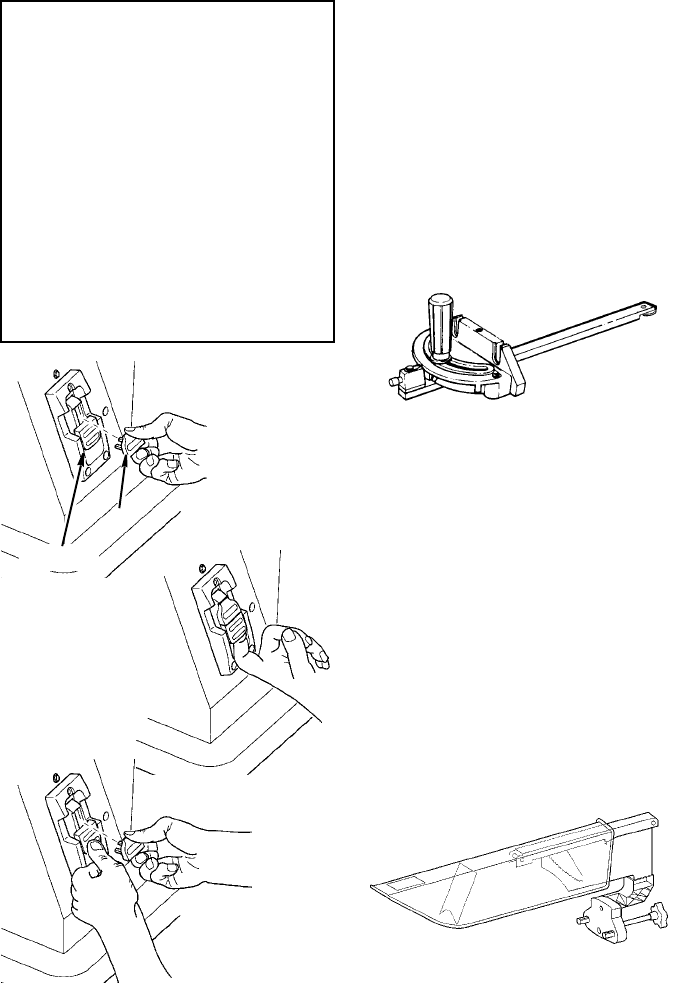
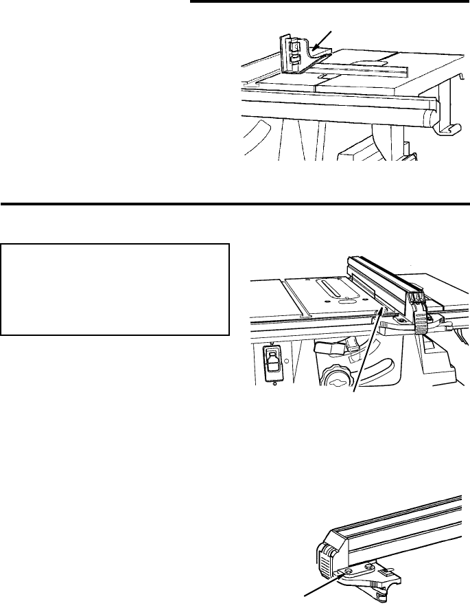
23. Blade Guard Storage ...holds the
blade guard when making non-thru
cuts and transporting saw.
19
Blade Guard Storage
Holds the blade guard when making non-
thru cuts and transporting saw. Slide
blade guard in as shown. Snap bottom
edge of clear basket between latches on
base.
Wrench/Blade Storage
Conveniently stores arbor wrenches as
well as an extra sawblade. Secure
wrenches and sawblade with blade stor-
age washer and wing nut. Extra washers
are provided to separate blades and pre-
vent tooth damage.
Rip Fence Storage
Securely holds the rip fence when it is not
being used. To insert, place the top edge
in first and twist upward to snap in place.
To remove pull up on fence and rotate
bottom away from saw.
Miter Gauge Storage
Provides convenient storage for the miter
gauge when it is not being used. Slide
miter gauge in place as shown. To
remove miter gauge release latch and lift
straight up.
Guard
Latches
Wing Nut
Blade
Wrench
Fence
Miter Gauge
Latch
20
Alignment
Tools Needed
Remove Foam Motor Support
A block of foam was placed under the
motor at the factory for shipping. Lift up
one edge of the saw base and remove the
foam.
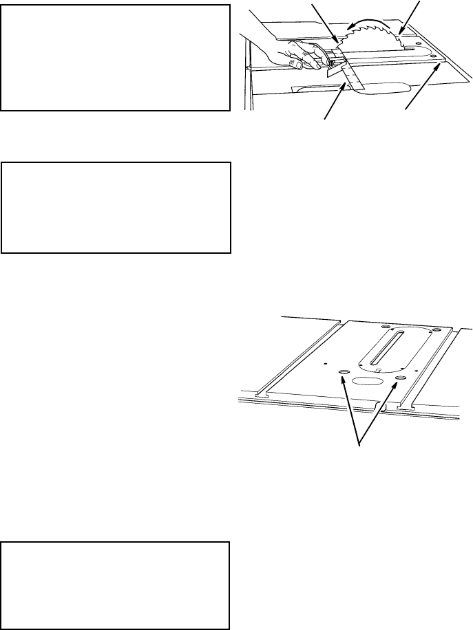
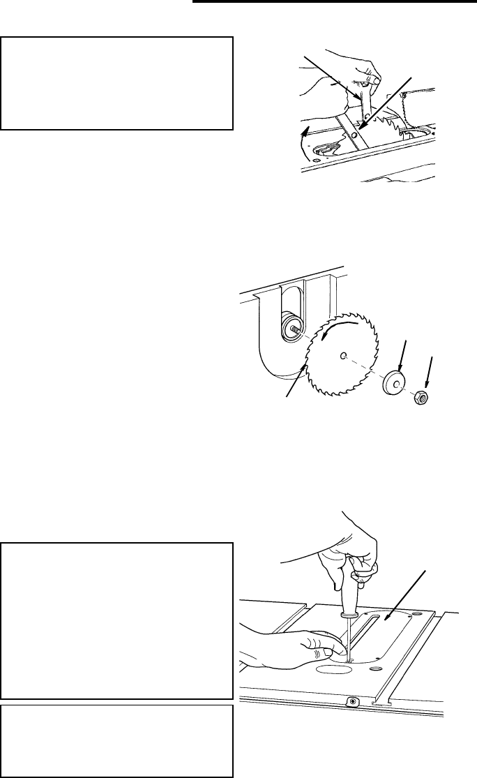
Checking Table Insert
WARNING: To reduce the risk of
injury from accidental start, make
sure switch is “OFF” and plug is
not connected to power source
outlet.
1. Insert should be flush with table top.
Check as shown. Loosen flat head
screw that holds insert and adjust the
four set screws as necessary. Tighten
flat head screw. Do not tighten screw to
the point where it bends the insert.
CAUTION: Insert must be even
with the table surface. Inserts too
high or low can let the workpiece
“snag” or catch on uneven
edges. Workpiece could twist
and kickback.
2. To remove insert.
a. Make sure saw is off and unplugged.
b. Loosen flat head screw.
c. Lift insert from front end, and pull
toward front of saw.
3. To replace insert.
a. Make sure saw is off and unplugged.
b. Place insert into insert opening in
table and push toward rear of saw to
engage spring clip and until keyslot
in insert will drop over flat head
screw. Tighten screw.
c. Do not tighten screw to the point
where it bends the insert.
Combination
Square
Combination Wrenches
3/8, 7/16 In. 1/2 In. 9/16 In.
Phillips Screwdriver
Hex “L” Wrenches
Combination
Square
3/32 In., 5/32 In., 3/16 In.
Combination Square must be true. Check
it’s accuracy as shown below.
Draw light line on
Should be no gap or overlap here when
square is flipped over in dotted position.
board along edge Select the straight edge of
NOTE: The square and
straight edge are used to
3/4” thick board. This edge
must be perfectly straight.
align the saw. They must
be accurate if the saw is
to be aligned properly.
Table Insert
3/32 In.
Hex “L” Wrench
Flat Head
Screw
21
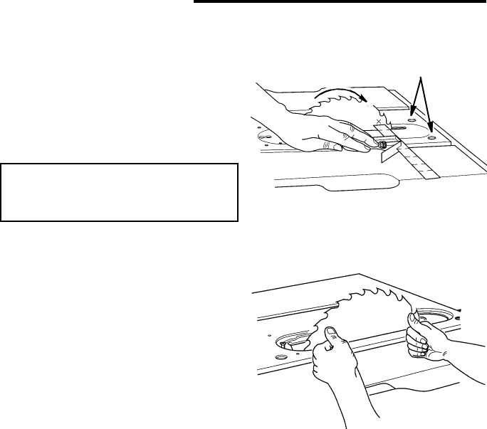
Checking Heeling Adjustment or
Parallelism of Sawblade to Miter
Gauge Groove
While cutting, the material must move in a
straight line parallel to the sawblade.
Therefore, both the miter gauge groove
and the rip fence must be parallel to the
sawblade.
WARNING: The blade must be
parallel to the miter gauge
groove. Misaligned blades could
bind on workpiece. Workpiece
could suddenly kickback. You
could be cut or hit.
If the sawblade is not parallel to the miter
gauge groove, the blade will bind at one
end of the cut. This is known as “Heeling”.
WARNING: To reduce the risk of
injury from accidental start, make
sure switch is “OFF” and plug is
not connected to power source
outlet.
To check for parallelism:
1. Raise blade all the way up.
2. Mark an “X” on one of the teeth which
is set (bent) to the right.
3. Place the head of a combination
square in the groove. Adjust blade of
square so that it just touches the tip of
the marked tooth.
4. Move square to rear, rotate blade to
see if marked tooth again touches
blade of square.
5. If tooth touches square the same
amount at front and rear, sawblade is
parallel to miter gauge groove.
6. If tooth does not touch the same
amount, the mechanism underneath
must be adjusted to make the blade
parallel to groove.
WARNING: To reduce the risk of
injury from accidental start, make
sure switch is “OFF” and plug is
not connected to power source
outlet.
Sawblade
Combination
Square
Miter Gauge
Groove
Marked
Tooth
x
Alignment
Screws
22
Alignment (continued)
NOTE: Always review the section "Check-
ing Blade Parallel to the Miter Gauge
Groove" before proceeding with this sec-
tion.
7. Loosen 1/2 turn the four alignment
screws in the top of table next to the
sawblade. This will allow the mecha-
nism below the table to be shifted
sideways.
CAUTION: Blade tips are sharp,
to move, grasp blade as shown
to avoid injury.
8. Push on side of blade and move it to
either the right or left as needed to
make the square touch the same
amount front and rear. Tighten one
screw.
9. Check with square to determine if
marked tooth touches square by the
same amount at front and rear.
If it does, alternately tighten the other
three screws.
If it does not, loosen screw and move
blade the required amount.
10. Recheck blade clearance to table
insert to make sure blade does not hit
at either 90 or 45 degree blade tilt.
Alignment
Screws
23
Checking Blade Tilt, or Squareness
of Blade to Table
When the bevel pointer is pointing directly
to the “0” mark on the bevel scale, the
sawblade should make a square cut 90°
to the table.
WARNING: For your own safety,
turn switch “OFF” and remove
plug from power source outlet.
To Check For Squareness, 90°
Position
1. Raise blade all the way up.
2. Loosen the blade tilt lock lever and push
the elevation wheel in and to the left as
far as possible and tighten the blade tilt
lock lever.
3. Place the square against blade. Make
sure square is not touching the tip of one
of the saw teeth.
A. If blade is square to table
1. Check pointer. If pointer does not
point to the “0” mark on the bevel
scale, loosen the pointer adjusting
screw and adjust pointer using
medium screwdriver. Retighten
screw.
B. If blade is not square to table, the
90° stop screw must be adjusted.
1. Loosen 90° stop screw three to
four turns using 5/32 inch hex “L”
wrench.
2. Loosen blade tilt lock lever. Turn
handwheel until blade is 90° to the
table. Tighten blade tilt lock lever.
3. Screw 90° stop screw in until it
stops. Check for squareness and
readjust screw, if necessary.
4. Check pointer as described in
step A.
Square Blade
Pointer at
0° Position
90°
Stopscrew
24
Alignment (continued)
To check for alignment, 45° Position
1. Loosen the blade tilt lock lever and
push elevation wheel in and to the right
as far as possible and tighten the blade
tilt lock lever.
2. Place an accurate square against blade.
Make sure square is not touching the tip
of one of the saw teeth.
A. If blade is 45° to table;
1. Check pointer. If pointer does not
point to the 45° mark on the scale,
the scale must be adjusted.
2. Loosen two screws on scale and
adjust scale up or down until
pointer points to 45° mark.
B. If blade is not 45° to table, stop
screw and scale must be adjusted.
1. Loosen 45° stop screw three to
four turns using 5/32 inch set-
screw wrench.
2. Loosen blade tilt lock lever. Turn
handwheel until blade is 45° to the
table. Tighten blade tilt lock lever.
3. Screw 45° stop screw in until it
stops. Check once again and
readjust screw, if necessary.
4. Check pointer as described in step
A above.
Scale Screws
45°
Stopscrew
25
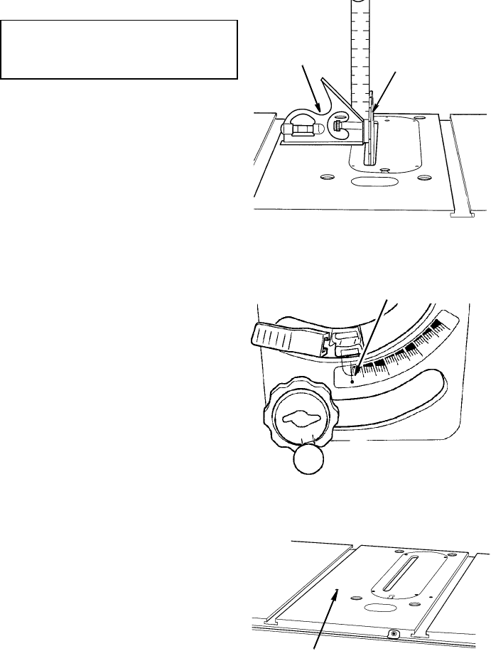
Adjusting Rip Fence Guide Bars
Aligning Rip Fence Guide Bars
1. Position rip fence over right end of main
table. While holding up rear of rip fence
engage front end of rip fence onto the
front guide bar. Now lower rip fence
down onto table.
2. Open owners manual so that 8 pages
are separated from the rest of the book.
Use these pages like a feeler gage to
set the spacing between the bottom of
the fence and the table top.
3. Rip fence should clear saw table sur-
face just enough to allow eight pages to
slide back and forth under rip fence. If
rip fence is too high or too low, loosen
the four nuts under the table and the
screw that secures rip scale at front of
main table. Release table lock, position
fence inside table extension lock lever.
Adjust front bar up and down as
required. Wrench tighten front right nut
only.
4. Adjust rear guide bar, as noted above.
Wrench tighten rear right nut.
5. Reposition fence over left end main table.
6. Adjust front guide bar up or down as
needed so the rip fence clears the saw
table surface just enough to allow the 8
pages of the owners manual to slide
back and forth underneath the rip
fence. Wrench tighten the front left nut
first and then the other remaining two
nuts at the front of the main table.
7. Adjust rear guide bar, as noted above.
Wrench tighten the rear left nut first
then the other two nuts at the rear of
the main table.
8. Slide fence left and right over main
table to insure clearance.
9. Tighten rip scale hold down screw.
Owners Manual
8 Pages
Rip Scale
Hold Down
26
Alignment (continued)
Aligning Sliding Table Extension
1. Lock table extension lever.
2. Loosen the four nuts underneath the
sliding table extension.
3. Use a combination square to make sure
the top of the sliding table extension is
the same height as the main table.
4. Tighten four nuts. Recheck and read-
just if necessary.
Rip Fence Alignment Adjustment
WARNING: A misaligned fence
can cause kickbacks and jams.
To reduce the risk of injury, fol-
low these instructions until the
fence is properly aligned.
The rip fence must be PARALLEL with
the sawblade and miter gauge grooves.
Clean any debris off the fence guide bars.
Move fence until it is along the side of the
right miter gauge groove and lock it. It
should be parallel to groove. If it is not:
a. Unlock fence.
b. Loosen the four hex head screws
located to each side of the rip fence
handle.
c. Place the blade of the combination
square in the right miter gauge
groove as shown.
d. Slide the fence against the blade of
the combination square as shown.
Carefully lock the fence in this posi-
tion.
e. Alternately tighten the hex head
screws.
f. Recheck alignment.
g. Repeat steps as needed until rip
fence is correctly aligned.
Combination Square
Miter Gauge Groove
Hex Head Screws
for Adjusting Fence
Parallelism
27
Rip Fence Lock Lever Adjustment
The rip fence lock lever, when locked
down, should hold the rip fence securely.
The lever should not be difficult to push
down and lock.
To assure proper fence lock adjust-
ment:
a. Raise lock lever and push fence
head toward rear of saw.
b. Hold fence head down onto front
guide bar while lifting rear of fence up
and down.
c. Tighten adjusting nut until fence
clamp just barely touches rear guide
bar.
d. This should provide the best fence
adjustment possible without over
tightening.
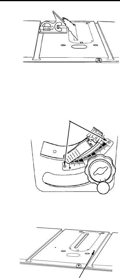
Adjusting Rip Indicator
1. Raise the blade up approximately 1".
2. Use a ruler to position the rip fence 6"
to the right of the blade as shown. Lock
the rip fence.
3. The rip indicator should read 6".
If not:
• Slightly loosen the Phillips head
screw.
• Slide the indicator left or right as
required.
• Tighten the Phillips head screw.
Adjusting
Nut
Fence
Rear Guide
Clamp
Fence Clamp and Rear Guide Bar
Should Barely Touch When
Fence is Raised
Bar
6"
Rip Indicator
28
Alignment (continued)
Checking Sliding Table Extension
Lock the table extension lock lever. Pull-
push on the sliding table extension. It
should not move.
WARNING: To reduce the risk of
thrown workpiece, do not use
with extension lock lever
unlocked.
If the sliding table extension moves
when locked:
1. Release the table extension lock lever.
2. Find the front hex coupling located
underneath the front table.
3. Loosen the hex locking nut.
4. Turn the hex coupling counterclock-
wise.
5. Lock the table extension lock. Pull-push
on the sliding table extension. Readjust
hex coupling if necessary. Tighten the
hex locking nut against coupling.
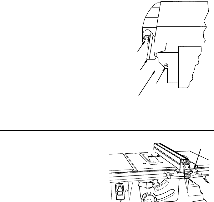
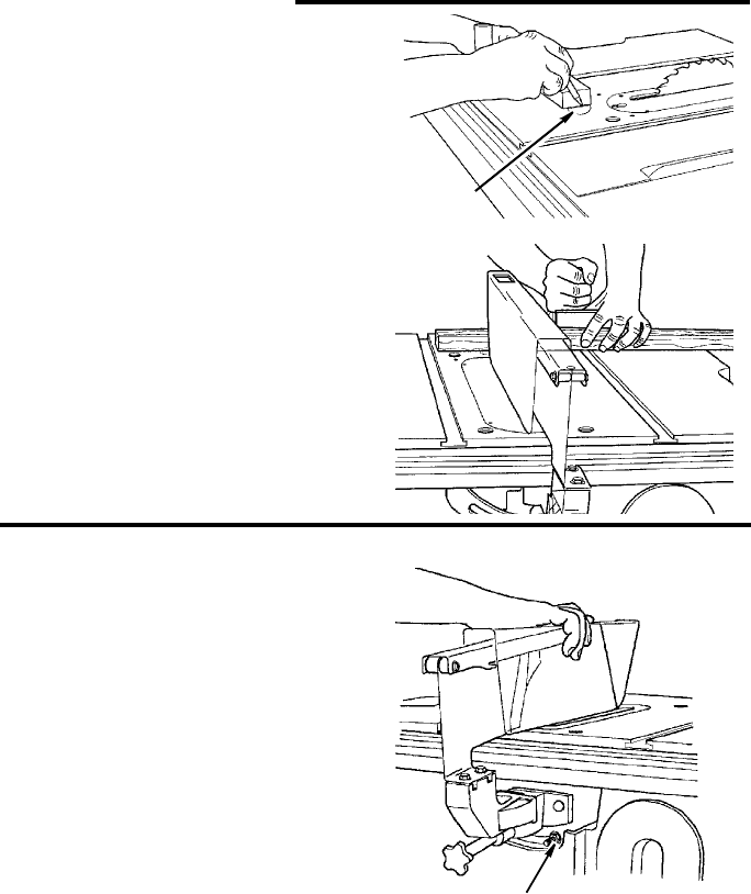
Installing Blade Guard
1. Locate the blade guard.
2. Two (2) locator pins are on the blade
guard. These locator pins fit into match-
ing holes on a bracket located on the
table saw trunnion.
3. Turn the blade guard locking knob
clockwise to securely attach the blade
guard in place.
Front Hex
Coupling
Hex Locking
Nut
Pin
Blade Guard
Locking Knob
29
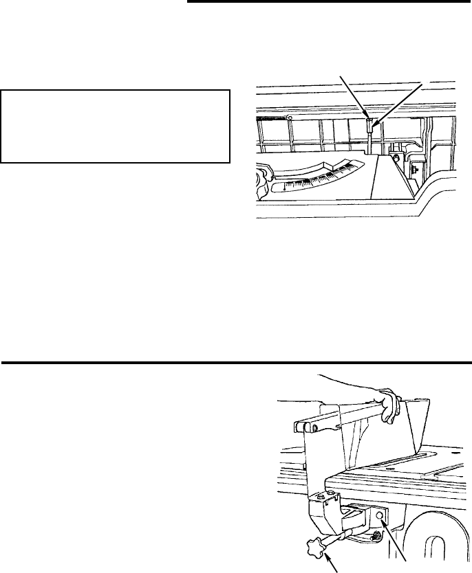
Aligning Blade Guard
IMPORTANT: To work properly, the
spreader must always be adjusted so the
cut workpiece will pass on either side of
the spreader without binding or skewing
to the side.
NOTE: The spreader is thinner than the
width of the cut (kerf) by approximately six
thicknesses of paper.
1. Raise blade all the way up, making
sure it is square with table.
2. Use a wrench to loosen the screw
that secures the spreader support to
the spreader mount.
3. Raise blade guard. Lift up both anti-
kickback pawls. Insert a large set
screw wrench in the notches of the
pawls to hold the pawls out of the
way.
4. Place a square against the spreader
as shown. Use a wrench to tighten
the screw.
5. Make two folds in a small piece (6 x 6
inch) of ordinary newspaper making
three thicknesses.
The folded paper will be used as
“spacing gauge”.
6. Using 7/16 wrench loosen the 1/4-20
hex head screws so the spreader can
slide sideways.
7. Place rip fence on the right hand side
of table. Carefully move it against
blade so that it is parallel to the blade,
and just touches tips of saw teeth.
Tighten rip fence lock lever.
8. Insert folded paper between spreader
and fence.
9. Hold spreader flat against folded
paper and fence. Tighten screws
using 7/16 inch wrench.
10. To remove blade guard and spreader,
loosen the blade guard locking knob.
Do not loosen other screws. This
allows you to remove and replace the
guard for non-through cuts without
disturbing the spreader alignment.
1/4-20 Hex Head Screws
Wood
Blade
Paper
Spreader
Kerf
Folded
Paper
Screw
Combination
Square
30
Alignment (continued)
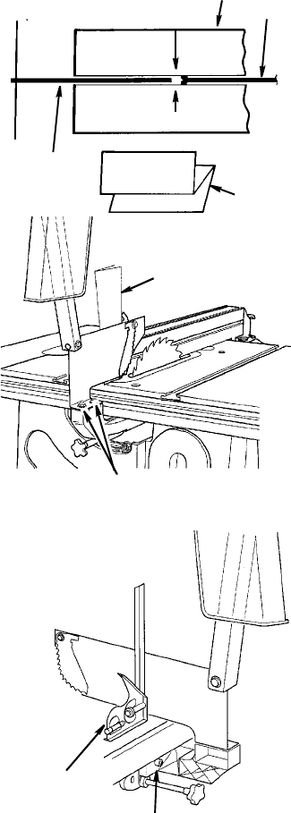
Removing and Installing Sawblade
WARNING: To reduce the risk of
injury from accidental start, turn
switch “OFF” and remove plug
from power source outlet before
removing or installing sawblade.
a. Raise blade guard, remove insert,
elevate blade to its highest point.
b. To remove blade, hold arbor wrench
securely, pull arbor nut wrench
towards the front of the table.
c. To tighten arbor nut, hold arbor
wrench securely, push arbor nut
wrench towards the rear of the table.
When installing the blade, make sure
the teeth are pointing toward the front
of the saw and that the blade and col-
lars are clean, and free from any burrs.
The hollow side of the collar must be
against the blade.
Always tighten the arbor nut securely.
NOTE: When using the dado or mold-
ing head, it is not necessary to install
the outer (loose) blade collar.
d. Lower the blade below the table.
e. To replace insert, place insert into
opening in table and push toward
rear of saw to engage rear spring on
insert and until key slot in insert will
drop over screw. Tighten screw. Do
not tighten screw to the point where it
will deflect the insert.
WARNING: To reduce the risk of
injury from a thrown workpiece,
blade parts, or blade contact,
never operate saw without the
proper insert in place. Use the
sawblade insert when sawing.
Use the proper size dado/mold-
ing insert for dado blades and
molding heads.
WARNING: For your own safety,
turn switch “OFF” and remove
plug from power source outlet
before making any adjustments.
Tighten
Closed End
Arbor Nut
Wrench
Open End Arbor
Shaft Wrench
Collar
Arbor Nut
Top Teeth Pointing
to Front of Saw
Blade Insert
31
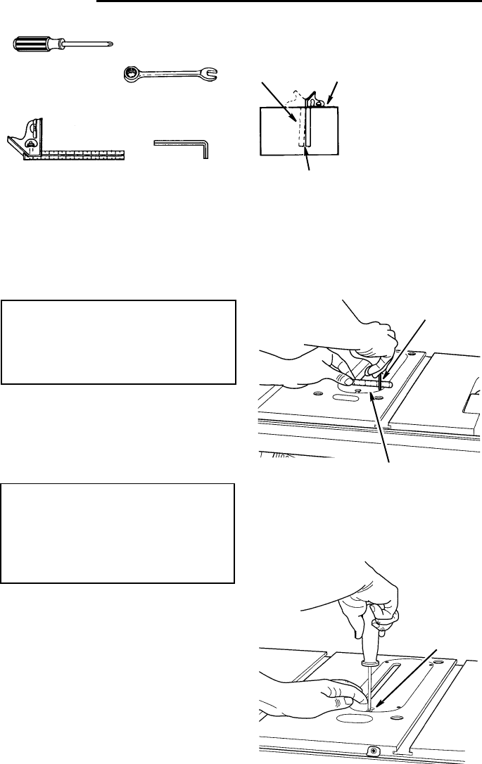
Miter Gauge Alignment
NOTE: The graduations are manufac-
tured to very close tolerances which pro-
vide ample accuracy for fine
woodworking. In some cases where
extreme accuracy is required, when mak-
ing angle cuts, for example, make a trial
cut and then recheck it.
There are adjustable screw stops for
the stop pin at 0° and 45° right and
left positions for conveniently setting
the miter gauge to cut miters at these
standard angles.
Adjusting Stop Screws
A. Loosen lock nut of screw for 0° stop.
B. Place 90° square against the miter
gauge bar and the face of the miter
gauge head.
C. If adjustment is needed loosen han-
dle of miter gauge. Adjust miter
gauge head flush to square. Tighten
lock knob.
D. Adjust stop screw until it rests
against the stop pin and tighten lock
nut.
E. Adjust 45°, left and right using a 45°
triangle or a protractor of a square
using the above procedure.
The miter gauge head should swivel
smoothly on the bar after the knob is loos-
ened. To adjust this swivel movement:
A. Loosen the knob.
B. Loosen set screw with a 2.5mm hex
wrench.
C. If the head is too loose turn the flat-
head screw in a clockwise direction.
If the head is too tight and will not
swivel smoothly turn the flathead
screw counterclockwise.
D. Tighten set screw.
Bar
Knob Miter Gauge
Head
Stop Pin
Pointer
Adjustment
Screw
Flat Head
Screw
Set Screw
32
Alignment (continued)
Marking the Ind-I-Cut:
a. With blade 90° (square to table) and
miter gauge in left groove, cross cut
a piece of wood holding the wood
firmly against miter gauge.
b. Pull miter gauge back until freshly cut
edge of wood is over disk. Using a
sharp pencil, mark a line on disk at
freshly cut edge of wood.
c. With miter gauge in right hand
groove, follow same procedure and
mark another line on disk.
d. These lines indicate the “path” of the
cut (kerf) made by the sawblade.
e. When cutting the workpiece, line up
mark on workpiece with line on disk.
NOTE: When the blade is changed, or a
dado/molding head installed these lines
can be erased and reset.
Adjusting Bevel Lock
1. Release blade tilt lock lever and bevel
blade to 45°.
2. Lock blade tilt lock lever, push in to dis-
engage the outer hub of the elevation/
bevel handwheel and with moderate
force attempt to move handwheel
toward the 0° bevel.
3. If blade tilt mechanism cannot be
moved, no additional adjustment is nec-
essary.
4. If blade tilt mechanism can be moved
adjust the blade tilt lock nut by rotating
clockwise 1/4 turn.
5. Repeat steps 3 and 4 as necessary.
6. Release hub of the elevation/bevel
handwheel and move blade tilt mecha-
nism back to 0°.
Marking
Using
Ind-I-Cut
Ind-I-Cut
Blade Tilt
Lock Nut
33
Mounting Your Saw
Mounting Table Saw to Workbench
or Legset
WARNING: To reduce the risk of
injury from accidental start,
make sure switch is "OFF" and
plug is not connected to power
source outlet.
WARNING: To reduce the risk of
injury from kickback or saw
movement the saw must be
properly secured to a sturdy
workbench, cabinet or legset.
Casters if provided on the cabi-
net or legset must be locked
during saw operation. If there is
any tendency for the saw to
move or rock during operation,
this must be corrected immedi-
ately.
If table saw is to be used in a permanent
location, it should be fastened securely to
a firm supporting surface such as a work-
bench, or legset using the mounting
holes.
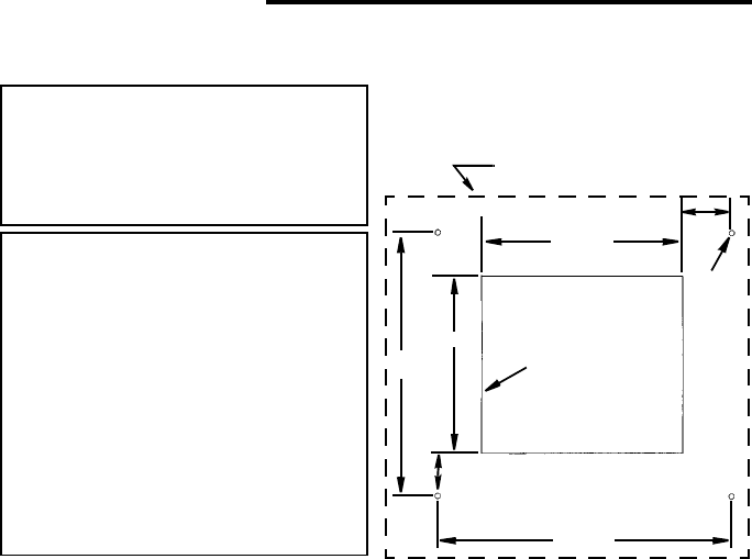
Workbench Mounting Using
Hardware
When mounting table saw to a workbench
and using a vacuum hookup, holes should
be drilled through the supporting surface
of the workbench using the dimensions
illustrated.
If a vacuum is not used, an opening must
be made in the workbench using the
dimensions illustrated, so the sawdust
can fall away from the saw base area.
Table Saw Mounting Procedures
1. Locate the proper hole mounting dia-
gram for your desired type of table saw
mounting.
2. Mark the hole locations and cutout
opening if vacuum is not used. Drill the
holes and cut out the area to allow saw-
dust to fall away from the base if a vac-
uum is not being utilized.
Workbench Surface
Diagram of Workbench Mounting Holes
(Front of Table Saw)
15-5/16"
3/8"
23-3/4"
Opening if
is not used
Vacuum
21-5/16"
3"
16-3/4"
4"
Dia.
3. Place the table saw on the mounting
surface and align the four holes.
4. Insert four (4) 1/4-20 screws that are
long enough for washers and nuts
which will properly secure the table saw
to the mounting surface.
NOTE: Mounting hardware (bolts, nuts,
washers etc.) are not supplied with the
saw.
34
Mounting Your Saw (continued)
Mounting Table Saw to RIDGID
Universal Power Tool Legset
#AC9910
1. Assemble legset per instructions.
2. Locate the four (4) “TS” layout points on
the particle board tables.
3. Drill the four (4) above holes.
4. Insert four (4) 1/4-20 screws that are
long enough for washers and nuts
which will properly secure the table saw
to the legset. Tighten hardware.
NOTE: Mounting hardware (bolts, nuts,
washers, etc.) are not supplied with the
saw.
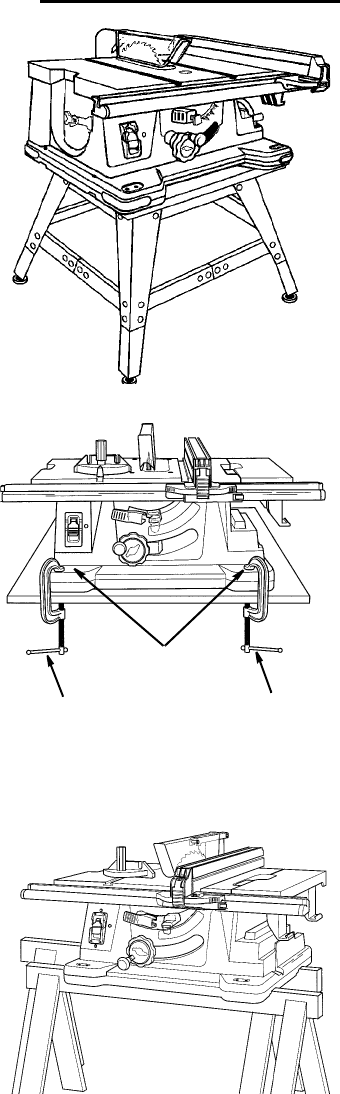
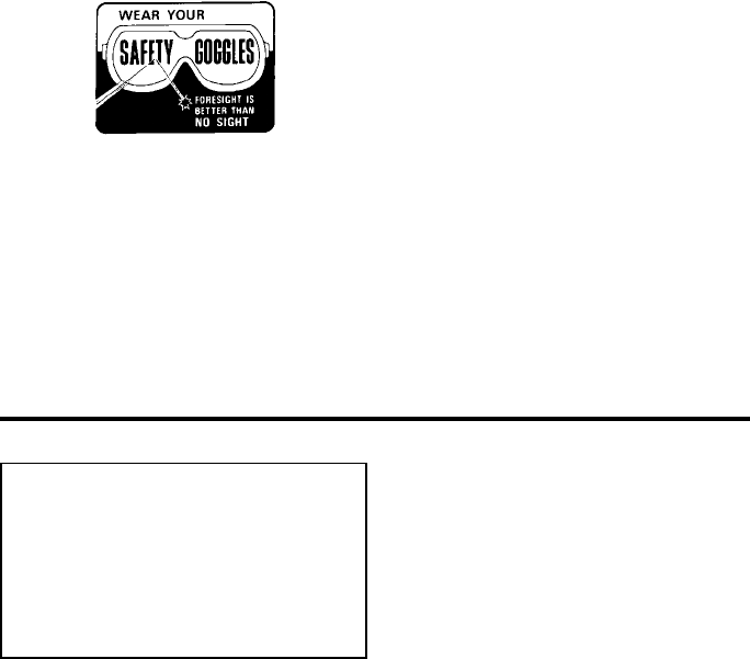
Workbench Mounting Using "C"
Clamps
An alternative method of securing your
table saw is to fasten the saw base with
"C" clamps.
1. Follow instructions for mounting to
workbench, substitute "C" clamps at
each mounting screw location.
2. Securely clamp saw to workbench
using four "C" clamps, as shown.
Supporting surface where saw is to be
mounted should be examined carefully
after mounting to insure that no move-
ment can occur during use. If any tipping,
sliding or walking is noted, secure the
workbench or cabinet before operating
the table saw.
Supporting Table Saw with
Sawhorses
The table saw has provisions for being
supported by sawhorses. The sawhorse
can be built with the 2" x 4"crosspieces
either vertical or horizontal. Make sure the
sawhorses are secure. Holes for securing
unit to sawhorse(s) are provided.
"C" Clamps
(Front and Rear)
Mounting
Screw Location
Diagram of Clamping Table Saw
"C" Clamp
to Workbench

35
Safety Instructions for Basic Saw Operations
Before Each Use
Inspect your saw.
• To reduce the risk of injury from
accidental starting, turn the switch
off, unplug the saw, and remove
the switch key before raising or
removing the guard, changing the
cutting tool, changing the setup, or
adjusting anything.
• Check for alignment of moving
parts, binding of moving parts,
breakage of parts, saw stability,
and any other conditions that may
affect the way the saw works.
• If any part is missing, bent or bro-
ken in any way, or any electrical
part does not work properly, turn
the saw off and unplug the saw.
• Replace damaged or missing parts
before using the saw again.
• Use the sawblade guard, spreader
and anti-kickback pawls for any
thru-sawing (whenever the blade
comes through the top of the work-
piece). Make sure the anti-kickback
pawls work properly. Make sure the
spreader is in line with sawblade.
• Remove adjusting keys and
wrenches. Form a habit of check-
ing for and removing keys and
wrenches from table top before
turning saw on.
• Make sure all clamps and locks are
tight and no parts have excessive
play.
To Reduce the Risk of Injury From Jams, Slips Or Thrown Pieces
(Kickbacks Or Throwbacks)
Inspect Your Blade.
• Choose the right blade or cutting
accessory for the material and the
type of cutting you plan to do.
• Never use grinding wheels, abra-
sive cutoff wheels, friction wheels
(metal cutting blades) wire wheels
or buffing wheels. They can fly
apart explosively.
• Cut only wood, wood like or plastic
materials. Do not cut metal.
• Choose and inspect your cutting
tool carefully:
- To reduce the risk of cutting tool
failure and thrown shrapnel (bro-
ken pieces of blade), use only 10”
or smaller blades or other cutting
tools marked for speeds of 5000
rpm or higher.
- Always use unbroken, balanced
blades designed to fit this saw’s
5/8 inch arbor.
- When thru-sawing (making cuts
where the blade comes through
the workpiece top), always use a
10 inch diameter blade. This
keeps the spreader in closest to
the blade.
- Do not over tighten arbor nut.
Use arbor wrenches to “snug” it
securely.
- Use only sharp blades with prop-
erly set teeth. Consult a profes-
sional blade sharpener when in
doubt.
- Keep blades clean of gum and
resin.
- Never use the saw without the
proper blade insert.
Inspect your work area.
• Keep work area clean.
• Cluttered areas and benches invite
accidents. Floor must not be slip-
pery from wax or sawdust.

36
Safety Instructions for Basic Saw Operations (continued)
• To reduce the risk of burns or other
fire damage, never use the saw
near flammable liquids, vapors or
gases.
• To reduce the risk of injury, don’t do
layout, assembly, or setup work on
the table while blade is spinning. It
could cut or throw anything hitting
the blade.
Plan your work
• Use the right tool. Don’t force tool
or attachment to do a job it was not
designed for.
Inspect your workpiece.
• Make sure there are no nails or for-
eign objects in the part of the work-
piece to be cut.
• When cutting irregularly shaped
workpieces, plan your work so it
will not slip and pinch the blade:
• A piece of molding for example,
must lie flat or be held by a fixture
of jig that will not let it twist, rock or
slip while being cut. Use jigs or fix-
tures where needed to prevent
workpiece shifting.
• Use a different, better suited type
of tool for work that can’t be made
stable.
Plan your cut.
• To reduce the risk of kickbacks and
throwbacks which occur when a
part or all of the workpiece binds on
the blade and is thrown violently
back toward the front of the saw:
- Never cut Freehand. Always use
either a rip fence, miter gauge or
fixture to position and guide the
work, so it won’t twist or bind on
the blade and kickback.
- Make sure there’s no debris
between the workpiece and its
supports.
• Use extra caution with large, very
small or awkward workpieces.
• Use extra supports (tables, saw
horses, blocks, etc.) for any work-
pieces large enough to tip when
not held down to the table top.
Never use another person as a
substitute for a table extension, or
as additional support for a work-
piece that is longer or wider than
the basic saw table, or to help feed,
support or pull the workpiece.
• Never confine the piece being cut
off, that is, the piece not against the
fence, miter gauge or fixture. Never
hold it, clamp it, touch it, or use
length stops against it. It must be
free to move. If confined, it could
get wedged against the blade and
cause a kickback or throwback.
• Never cut more than one work-
piece at a time.
• Never turn your table saw “ON”
before clearing everything except
the workpiece and related support
devices off the table.
Plan Ahead To Protect Your Eyes, Hands, Face and Ears
Dress for safety
• Do not wear loose clothing, gloves,
neckties or jewelry (rings, wrist
watches). They can get caught and
draw you into moving parts.
• Wear nonslip footwear.
• Tie back long hair.
• Roll long sleeves above the elbow.
• Noise levels vary widely. To reduce
the risk of possible hearing dam-
age, wear ear plugs or muffs when
using table saw for hours at a time.
37
• Any power saw can throw foreign
objects into the eyes. This can
result in permanent eye damage.
Always wear safety goggles, not
glasses, complying with ANSI
Z87.1 (or in Canada CSA Z94.3-
99) shown on package. Everyday
eyeglasses have only impact resis-
tant lenses. They are not safety
glasses. Safety goggles are avail-
able at many local retail stores.
Glasses or goggles not in compli-
ance with ANSI or CSA could seri-
ously hurt you when they break.
• For dusty operations, wear a dust
mask along with safety goggles.
Plan the way you will push the
workpiece through.
•Never pull the workpiece
through. Start and finish the cut
from the front of the table saw.
•Never put your fingers or hands
in the path of the sawblade or
other cutting tool.
•Never reach in back of the cutting
tool with either hand to hold down
or support the workpiece, to
remove wood scraps, or for any
other reason.
• Avoid hand positions where a sud-
den slip could cause fingers or a
hand to move into a sawblade or
other cutting tool.
• Don’t overreach. Always keep good
footing and balance.
• Push the workpiece against the
rotation of the blade, never feed
material into the cutting tool from
the rear of the saw.
• Always push the workpiece all the
way past the sawblade.
• As much as possible, keep your
face and body to one side of the
sawblade, out of line with a possi-
ble kickback or throwback.
• Set the cutting tool as low as possi-
ble for the cut you’re planning.
Reduce the Risk of Accidental
Starting.
• Make sure switch is “OFF” before
plugging saw into a power outlet.
Whenever Sawblade Is Spinning
WARNING: Don't allow familiar-
ity (gained from frequent use of
your table saw) cause a careless
mistake. Always remember that
a careless fraction of a second
is enough to cause a severe
injury.
• Before actually cutting with the
saw, watch it while it runs for a
short while. If it makes an unfamil-
iar noise or vibrates a lot, stop
immediately. Turn the saw off.
Unplug the saw. Do not restart until
finding and correcting the problem.
• Make sure the top of the arbor or
cutting tool turns toward the front of
the saw.
Keep Children Away.
• Keep all visitors a safe distance
from the table saw.
• Make sure bystanders are clear of
the table saw and workpiece.
Don’t Force Tool.
• Let the blade reach full speed
before cutting.
• It will do the job better and safer at
its designed rate.

38
Safety Instructions for Basic Saw Operations (continued)
• Feed the workpiece into the saw
only fast enough to let the blade
cut without bogging down or bind-
ing.
Before freeing jammed material.
• Turn switch “OFF”.
• Wait for all moving parts to stop.
• Unplug the saw.
• Check blade, spreader and fence
for proper alignment before starting
again.
• To reduce the risk of throwback
of cut off pieces.
• Use the guard assembly.
To remove loose pieces beneath or
trapped inside the guard.
• Turn saw “OFF”.
• Remove switch key.
• Wait for blade to stop before lifting
the guard.
Before Leaving The Saw.
• Turn the saw off.
• Wait for blade to stop spinning.
• Unplug the saw.
• Make workshop child-proof. Lock
the shop. Disconnect master
switches. Remove the yellow
switch key. Store it away from chil-
dren and others not qualified to use
the tool.
Work Feed Devices
Before cutting any wood on your saw,
study all of the “Basic Saw Operations”.
As you learn new table saw woodworking
techniques, you’ll see that many types of
cuts need different support and feeding
devices, known as jigs or fixtures. They
can help you make cuts more accurately.
By helping to steady the workpiece and
keep you away from the blade, they can
help you safely use your saw for certain
cuts.
Many people custom build their own jigs
and fixtures. Jigs and fixtures are often
designed for a particular cut.
You can use your table saw to easily
make many jigs and fixtures. To get you
started, we’ve included instructions for
some simple ones. After you have made a
few practice cuts, make up these jigs
before starting any projects. The use of
these devices is explained in “Basic Saw
Operations” section.
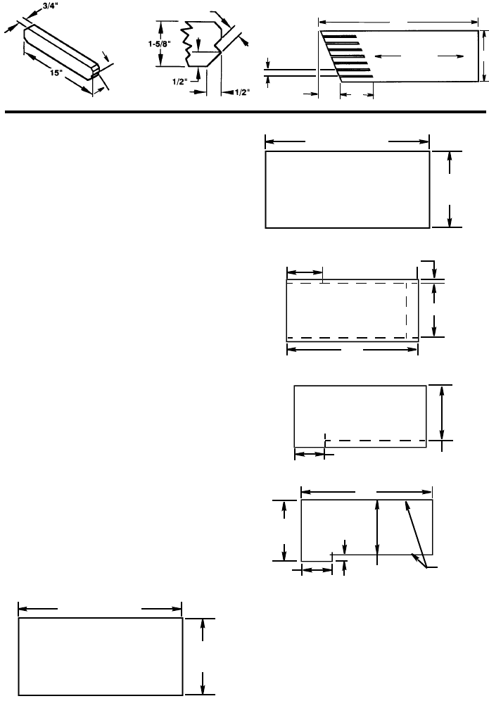
39
Push Stick
Make the push stick from a piece of solid
wood. Use a piece of 1 x 2 (3/4" x 1-5/8"
actual) by 15" long.
Make the featherboard from a piece of 8”
x 24” x 3/4” thick solid wood
Push Block (For Use with Auxiliary
Fence)
There are any number of ways to properly
cut your workpieces to make a push
block. The following steps describe one
way you can make a push block.
Making the base:
• Start with a piece of 3/8 inch plywood
at least 5-5/8 inches wide or wider and
12 inches long or longer.
• Make two ripcuts. Perform the first
ripcut along the side of the 3/8" wide
strip. Next, ripcut the 3/8" plywood to a
width of 5-1/8".
• Crosscut the 3/8" plywood to 12" long.
• Crosscut a 2-1/2" piece off the 3/8"
wide by 3/8" thick strip and save this
short piece for later.
The next cuts will create the 3/8" by 9-1/2"
notch in the base. Mark the long edge of
the board 2-1/2" from one end. Make a
crosscut into the edge on the mark, stop-
ping about 3/4" into the board. Set the
saw and rip the width to 4-3/4" along the
same edge as the stopped crosscut. Stop
the ripcut where the two cuts intersect.
Turn off the saw and remove the base
piece. The base should now measure as
shown.
Material for Push Block
Cutting Out the Base
Creating the Notch
Finished Base
Slightly Less Than Thickness
Of Workpiece Up to 3/8"
90° Notch
Kerfs About
5/16" Apart
24"
5"
4-1/2"
8"
Grain
At Least 12"
At Least
5-5/8"
3/8" Thick Plywood
Base
At Least 12"
At Least
5-5/8"
3/8" Thick Plywood
Handle
3/8"
5-1/8"
1st Cut
2nd Cut
3rd Cut
4th Cut
2-1/2" (save)
12"
4-3/4"
1st Cut 2nd Cut
2-1/2"
These Edges
Must Be
Parallel
12"
At Least
5-5/8"
2-1/2"
3/8"
4-3/4"
40
Work Feed Devices (continued)
Making the handle:
• Miter crosscut a piece of 3/4 inch thick
plywood to shape and size shown:
NOTE: The mitered corners can be any
size that looks like the drawing (about 1-1/2"
by 1-1/2").
Putting it Together
• Using good quality woodworking glue,
glue the 3/8" x 3/8" x 2-1/2" piece strip
saved earlier to the base as shown.
IMPORTANT: Do not use nails or screws.
This is to prevent dulling of the sawblade
in the event you cut into the push block.
• Position the handle at the center of the
plywood base as shown. Fasten them
together with glue and wood screws.
IMPORTANT: Make sure the screw heads
do not stick out from the bottom of the
base, they must be flush or recessed. The
bottom must be flat and smooth enough
to slide along the auxiliary fence you are
now ready to make.
Auxiliary Fence
Making the base:
• Start with a piece of 3/8 inch plywood
at least 5-1/2 inches wide or wider and
25-1/2 inches long or longer.
• Cut the piece to shape and size shown:
Making the side:
• Start with a piece of 3/4 inch plywood at
least 3 inches wide or wider and 25-1/2
inches long or longer.
• Cut the piece to shape and size shown:
• Optional: Drill three (3) holes in plywood
side similar to rip fence wood facing (see
page 31). The plywood side may either be
mounted to the rip fence using these three
holes and appropriate nuts and bolts or
clamped to the fence with “C” clamps.
Putting it together:
• Put the pieces together, as shown:
IMPORTANT: Make sure the screw heads
do not stick out from the bottom of the
base, they must be flush or recessed. The
bottom must be flat and smooth enough
to rest on the saw table without rocking.
Cutting Out the Base
Cutting Out the Side
Finished Auxiliary Fence
3/8" Plywood Base
3/4" Plywood Handle
Screw Head Must Be
Flush Or Recessed
Glue
Only
3/8" Thick Plywood Base
25-1/2"
5-1/2"
3/4" Thick Plywood Side
25-1/2"
3"
3/4" Plywood
3/8"
4-3/4"
This face and this edge
must be parallel
Plywood
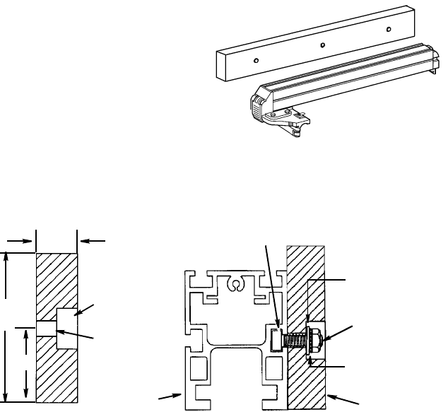
41
Fence Facing
Select a piece of smooth straight wood
approximately 3/4 inch thick, and the
same length as the rip fence.
Attach it to the fence with the three square
head bolts, nuts and washers. (See
“Hardware for Attaching Wood Facing”) in
Repair Parts Figure 4. To remove the fac-
ing, loosen the hex nuts, slide the facing
toward the rear and out of the fence slot.
If the fence facing is for use with feather
boards, it will need to be about 8" tall. For
use with molding heads and dado blades
the width should be at least 3".
Flat
Washer
Lockwasher
Hex
Wood Facing
Fence
Nut
Square Head
Bolt
1-3/8
9/32
Diameter
Hole
Counterbore
3/4 Diameter
x 3/8 Deep
3"
Minimum
3/4"
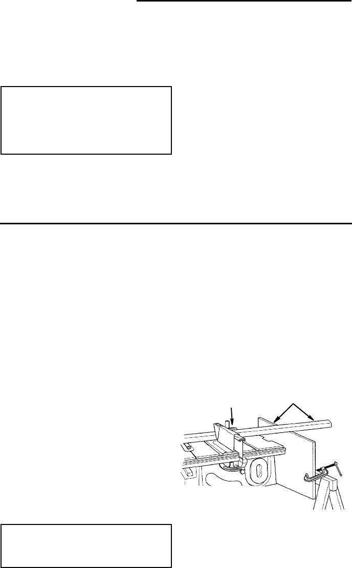
42
Basic Saw Operations
Using the Miter Gauge
The miter gauge is used when crosscut-
ting, miter cutting, bevel cutting, com-
pound miter cutting, dadoing and when
rabbeting across the end of a narrow
workpiece.
WARNING: For your own safety,
always observe the following
safety precautions in addition to
the safety instructions of pages 3
thru 9 and 35 thru 38.
Additional Safety Instructions for
Crosscutting
Before Starting:
• Never use the rip fence when crosscut-
ting except as specifically instructed.
•An auxiliary wood facing attached to the
miter gauge can help prevent work-
piece twisting and throwbacks. Attach it
to the slots provided. Make the facing
long enough and big enough to support
your work. Make sure, however, it will
not interfere with the sawblade guard.
•Use jigs or fixtures to help hold any
piece too small to extend across the full
length of the miter gauge face during
the cut. This lets you properly hold the
miter gauge and workpiece and helps
keep your hands away from the blade.
While cutting:
•To reduce the risk of blade contact,
always hold the miter gauge as shown
in the this section.
Crosscutting
Definition: A cutting or shaping operation
made across the width of a workpiece.
The graduations on the miter gauge pro-
vide ample accuracy for average wood-
working. In some cases where extreme
accuracy is required, make a trial cut and
then recheck it with a precision square, or
protractor.
NOTE: The space between the miter
gauge bar and the groove in the table is
held to a minimum during manufacturing.
For maximum accuracy when using the
miter gauge, always favor one side of the
groove in the table. In other words, don’t
move the miter gauge from side to side
while cutting but keep one side of the bar
riding against one side of the groove.
NOTE: Gluing a piece of sandpaper to the
face of the miter gauge head can help
prevent the workpiece from “creeping”
while it is being cut.
The miter gauge head is locked in posi-
tion by twisting the lock knob clockwise.
Always tighten it securely when in use.
WARNING: To reduce the risk of
blade contact or kickback, hold
miter gauge properly.
The miter gauge may be used in either of
the grooves in the table.
When using the miter gauge in the left
hand groove, hold the workpiece firmly
against miter gauge head with your left
hand, and grip the lock knob with your
right hand.
When using the miter gauge in the right
hand groove, hold the workpiece with
your right hand and the lock knob with
your left hand.
Always Support
Long Workpieces
Sandpaper
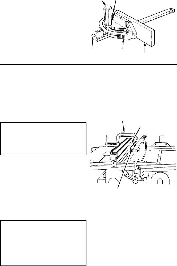
43
Crosscutting (continued)
Slots are provided in the miter gauge for
attaching an auxiliary facing to make it
easier to cut very long or short pieces.
Select a suitable piece of smooth wood,
drill two holes through it and attach with
screws. Make sure the facing does not
interfere with the proper operation of the
sawblade guard.
When cutting long workpieces, you can
make a simple support by clamping a
piece of plywood to a sawhorse. (As seen
on previous page.)
Repetitive Crosscutting
Definition: Cutting a quantity of pieces the
same length without having to mark each
piece.
• Follow all safety precautions and oper-
ational instructions for cross cutting.
• When making repetitive cuts from a
long workpiece, make sure it is ade-
quately supported.
WARNING: Never use the rip
fence as a direct length stop
because the cutoff piece could
bind between the fence and the
blade causing a kickback.
• When making repetitive cuts shorter
than 6 inches, clamp a block of wood 3”
long to the fence. Place fence at
desired position to act as a length stop.
• Slide the workpiece along the miter
gauge until it touches the block...hold
the workpiece securely against the
miter gauge.
• Make the cut...turn the saw off...remove
the piece after the blade has stopped
and before cutting the next piece.
WARNING: To reduce the risk of
kickback from twisting the work-
piece, when clamping the block
make sure that the end of the
block is well in front of the saw-
blade. Be sure it is clamped
securely.
Lock
Knob
Miter Gauge
Head
Stop Pin 45° Stop
Screw Auxiliary
Facing
“C” Clamp
Wood Block
Cut Off Piece
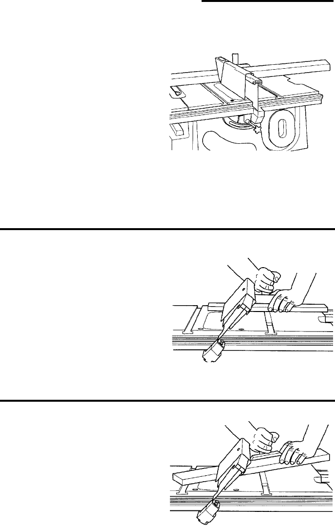
44
Miter Crosscutting
Miter cutting is cutting wood at an angle
other than 90° with the edge of the wood.
Follow the same procedure as you would
for crosscutting.
• Adjust the miter gauge to the desired
angle, and lock it.
• The miter gauge may be used in either
of the grooves in the table. Make sure it
is locked.
• When using the miter gauge in the left
hand groove, hold the workpiece firmly
against the miter gauge head with your
left hand, and grip the lock knob with
your right hand.
• When using the miter gauge in the right
hand groove, hold the workpiece with
your right hand and the lock knob with
your left hand.
Bevel Crosscutting
Bevel crosscutting is the same as cross-
cutting except that the wood is cut at an
angle...other than 90° with the bottom flat
side of the wood.
• Adjust the blade to the desired angle.
• Always use the miter gauge in the
groove to the right of the blade. It can-
not be used in the groove to the left
because the blade guard will interfere.
Hold the workpiece with your right hand
and the lock knob with your left hand.
• Use the auxiliary fence/work support for
additional support of the workpiece.
Compound Crosscutting
Compound cutting is a combination of
miter cutting and bevel crosscutting. The
cut is made at an angle other than 90° to
both the edge and the bottom flat side of
the wood.
• Adjust the miter gauge and the blade to
the desired angle...Make sure miter
gauge is locked.
Basic Saw Operations (continued)

45
Using the Rip Fence
Ripping, bevel ripping, resawing and rab-
beting are performed using the rip fence
together with the auxiliary fence/work
support, push stick or push block.
WARNING: For your own safety,
read and always observe all
safety precautions listed in man-
ual and on saw.
Additional Safety Instructions for
Rip Cuts
• Never use the miter gauge when rip-
ping
• Use a push stick whenever the fence is
2 or more inches from the blade.
• When thru sawing, use an auxiliary
fence and push block whenever the rip
cut is between 1/2 and 2 inches from
the blade.
• Never thru saw rip cuts narrower than
1/2 inch.
• Never rip anything shorter than 10”
long.
• When using a push stick or push block,
the trailing end of the workpiece must
be square. A push stick or block against
an uneven end could slip off or push the
workpiece away from the fence.
• A featherboard can help guide the
workpiece. (See “Basic Saw Operation-
Using Featherboards for Thru Sawing”
section.)
•Always use featherboards for any non-
thru sawing rip type cuts. (See “Basic
Saw Operations-Using Featherboards
for Non-thru sawing” section)
Before Starting:
•To reduce the risk of kickbacks and
slips into the blade, make sure the rip
fence is parallel to the sawblade.
• Before thru sawing, check the anti-kick-
back pawls. the pawls must stop a kick-
back once it has started. Replace or
sharpen anti-kickback pawls when
points become dull.
•Plastic and composition (like hard-
board) materials may be cut on your
saw. However, since these are usually
quite hard and slippery, the anti-kick-
back pawls may not stop a kickback.
Therefore, be especially careful in your
setup and cutting procedures.
While Thru sawing:
•To reduce the risk of kickbacks and
slips into the blade, always push for-
ward on the section of the workpiece
between the sawblade and the rip
fence. Never push forward on the piece
being cut off.
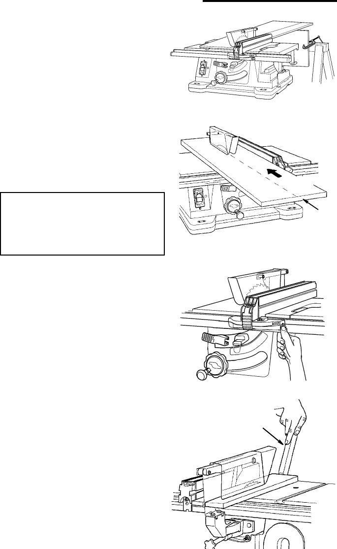
46
Ripping
Definition: Cutting operation along the
length of the workpiece.
Position the fence to the desired width of
rip and lock in place.
Before starting to rip, be sure:
1. Rip fence is parallel to sawblade.
2. Spreader is properly aligned with saw-
blade.
3. Anti-kickback pawls are functioning
properly.
When ripping long boards or large panels,
always use a work support. A simple sup-
port can be made by clamping a piece of
plywood to a sawhorse.
WARNING: To reduce the risk of
kickback, push forward only on
the part of the workpiece that
will pass between the blade and
the fence.
Keep your hands out of the blade path.
Feed the workpiece by pushing forward
only on the part of the workpiece that will
pass between the blade and the fence.
Stop your left thumb at the front edge of
the table. Finish the cut with the appropri-
ate pusher.
Use the micro-adjust mechanism to make
fine adjustments to the rip fence. To move
the rip fence push in on the micro-adjust
knob and rotate.
Once the trailing end is on the table:
When “width of rip” is 2" or wider, use the
push stick to push the work all the way
past the blade.
Blade
Path
Feed
Force
Push Stick
Basic Saw Operations (continued)
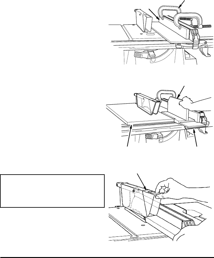
47
Ripping (continued)
When “width of rip” is narrower than 2" the
push stick cannot be used because the
guard will interfere...use the auxiliary
fence and push block.
Attach auxiliary fence to rip fence with two
“C” clamps or use “T” slot and hardware.
Feed the workpiece by hand along the
auxiliary fence until the end is approxi-
mately 1" past the front edge of the table.
Continue to feed using the push block.
Hold the workpiece in position and install
the push block by sliding it on top of the
auxiliary fence/work support (this may
raise guard).
WARNING: To reduce the risk of
injury from blade contact never
thru saw cuts narrower than 1/2"
wide.
Narrow strips thicker than the auxiliary
fence/work support may enter the guard
and strike the baffle. Carefully raise guard
only enough to clear the workpiece. Use
push block to complete cut.
Bevel Ripping Narrow Work
When bevel ripping material 6” or nar-
rower, use fence on the right side of the
blade only. This will provide more space
between the fence and the sawblade for
use of a push stick. If the fence is
mounted to the left, the sawblade guard
may interfere with proper use of a push
stick.
Auxiliary “C” Clamp
Fence
Push Block
Workpiece Auxiliary Fence
Baffle
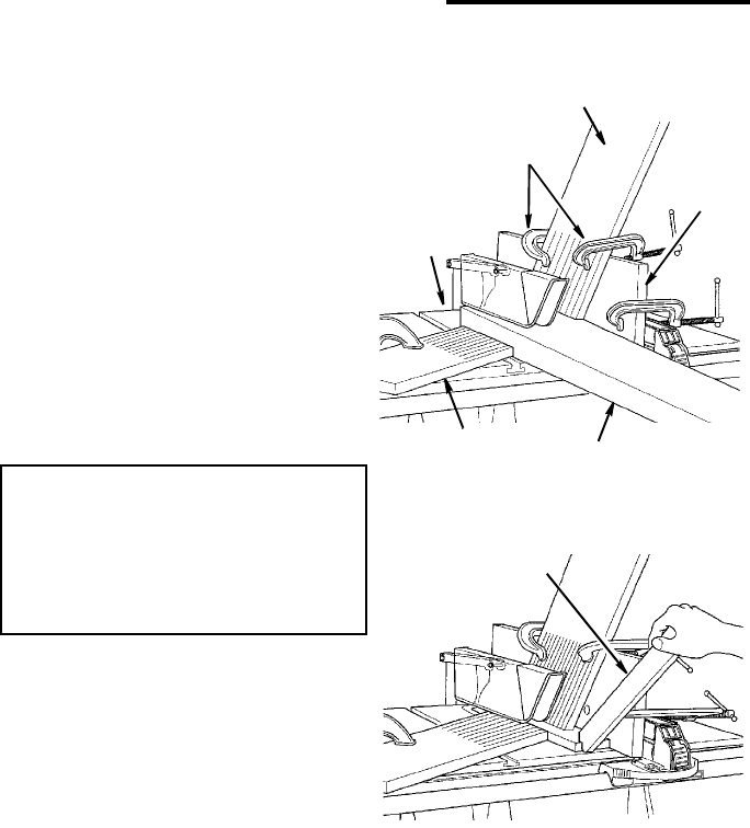
48
Using Featherboards for Thru
Sawing
Featherboards are not employed for thru
sawing operations when using the miter
gauge.
Featherboards are used to keep the work
in contact with the fence and table as
shown, and to help stop kickbacks.
Add a 7-1/2” high flat facing board to the
fence, the full length of the fence. The fac-
ing board may either be “C”-clamped to
the rip fence or held in place with appro-
priate nuts and bolts (see “Workfeed
Devices” section).
Mount featherboards to facing board and
table as shown, so that leading edges of
featherboards will support workpiece.
WARNING: Make sure the feath-
erboard against the edge
presses only on the uncut por-
tion (in front of the blade). It
might otherwise pinch the blade
in the kerf and cause a kickback.
Before starting the operation (switch
“OFF” and blade below table surface):
1. Install featherboards so they exert
pressure on the workpiece; be positive
they are securely attached.
2. Make sure by trial that the feather-
boards will stop a kickback if one
should occur.
Work
Support
“C” Clamps
Featherboard
Facing
Board
Workpiece
Featherboard
Push
Stick
Basic Saw Operations (continued)
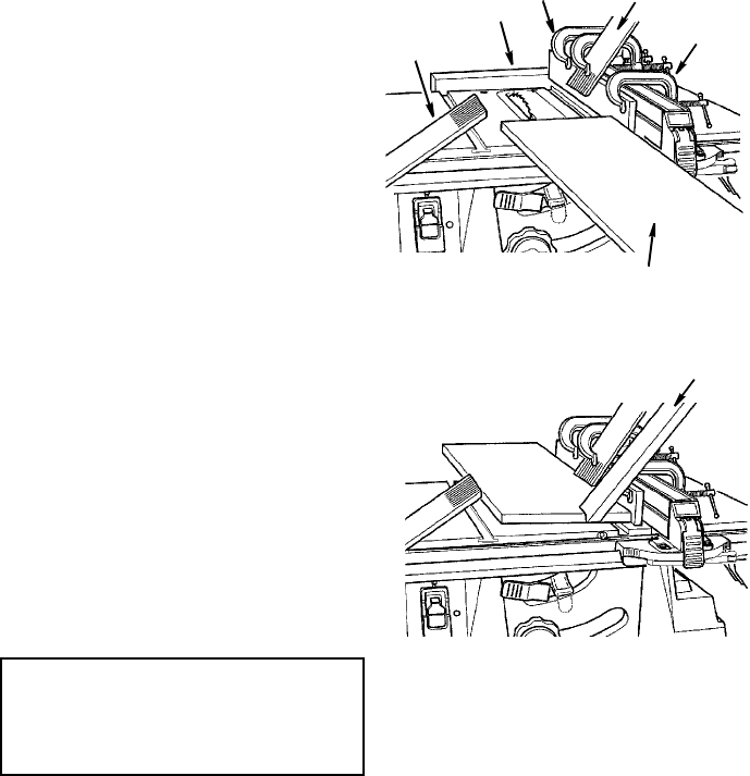
49
Using Featherboards for Non-Thru
Sawing
Featherboards are not employed during
non-thru sawing operations when using
the miter gauge.
Use featherboards for all other non-thru
sawing operations (when sawblade guard
must be removed). Featherboards are
used to keep the work in contact with the
fence and table as shown and to stop
kickbacks.
Add a 7-1/2” high flat facing board to the
fence, the full length of the fence.
Mount featherboards to facing board and
table as shown, so that leading edges of
featherboards will support workpiece until
cut is complete, and the workpiece has
been pushed completely past the cutter
(sawblade, dado-head, etc.) with a push
stick, as in ripping.
Before starting the operation (make sure
the switch is in the off position and the
blade is below the table):
1. Install featherboards so they exert
pressure on the workpiece; be positive
they are secure.
2. Make sure and try out the set-up to ver-
ify that the featherboards are correctly
positioned.
WARNING: For your own safety,
replace the sawblade guard as
soon as the non-thru sawing
operation is complete.
“C” Clamp
Work Support Featherboard
Featherboard
Facing
“C”
Clamp
Board
Push Stick
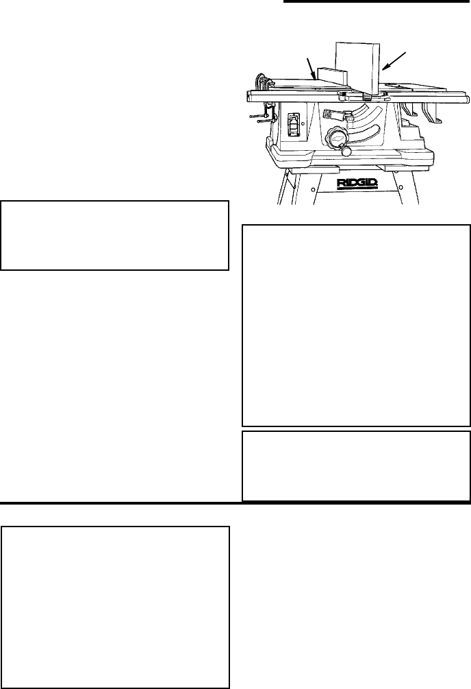
50
Basic Saw Operations (continued)
Resawing
Resawing is a rip cut made in a piece of
wood through its thickness. The piece is
typically positioned on its edge. If the
piece is narrower than 3-3/8" it can be
resawn in one pass with the blade guard
in place. Extra supports or fixtures will be
required when the edge resting on the
table is too narrow for the piece to be sta-
ble or when the fence interferes with the
blade guard. (See method described
below)
WARNING: Do not attempt to
resaw bowed or warped material.
It can’t be properly supported. It
could kickback or bind.
NOTE: To resaw a piece of wood wider
than 3-3/8”, or a piece needing extra sup-
port, it will be necessary to remove the
blade guard and use the auxiliary fence/
work support. (See “Workfeed Devices”.)
Construct an auxiliary fence/work support
as shown. Depending on the thickness of
the workpiece the width of the auxiliary
fence/work support will have to be made
so that it can be attached to the table saw
top with “C” clamps. Clamp the auxiliary
fence/work support to the table so that the
workpiece will slide easily without binding
between the two fences and it will not tilt
or move sideways.
WARNING: For your own safety
1. Do not “Backup” (reverse
feeding) while resawing
because this could cause a
kickback.
2. Make first pass to a depth
slightly more than one half the
width of the board.
3. Keeping the same face of
board against the fence rotate
it end over end and make the
second pass.
WARNING: For your own safety,
install blade guard immediately
upon completion of the resaw-
ing operation.
Using Carbide Tipped Blades
WARNING: To reduce the risk of
cutting tool failure and thrown
shrapnel (broken pieces of
blade) read and understand all
the warnings and instructions
which come with carbide tipped
blades. Failure to heed all car-
bide tipped blade warnings and
safety instructions can result in
serious injury.
Carbide is a very hard but brittle material.
Take care when mounting, using and stor-
ing carbide blades to prevent accidental
damage. Slight shocks, such as striking a
tip during handling, can seriously damage
the blade. Foreign objects in the work-
piece, such as wire or nails, can also
cause tips to crack or break off.
Before using a carbide tipped blade,
always examine the blade and tips for
damage. Look for bent teeth, a bent
blade, cracks, broken, missing or loose
carbide tips. Do not use a carbide tipped
blade if damage is found or suspected.
Do not use a carbide tipped blade without
all appropriate guards in place.
Mount blade securely in proper rotation
direction.
Never rotate a carbide tipped blade faster
than its maximum recommended speed.
Auxiliary Fence/
Work Support Workpiece
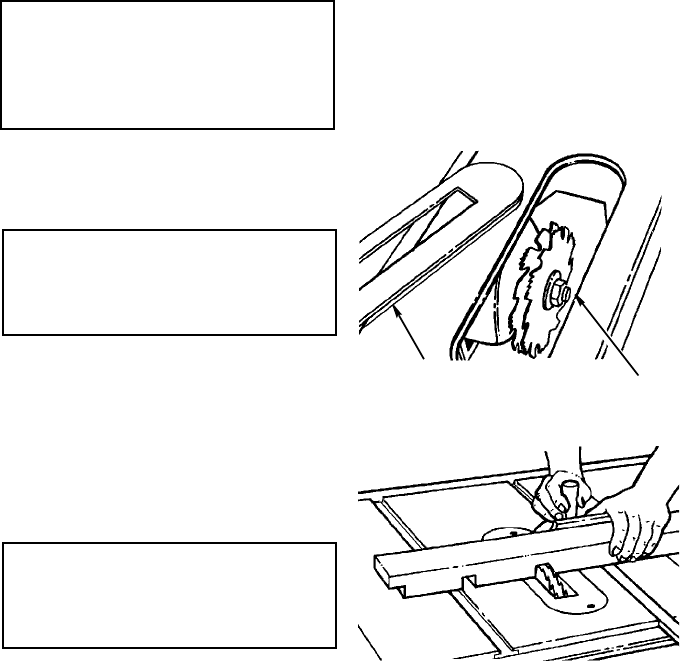
51
Dadoing
Dadoing is cutting a groove into the work-
piece. There are a wide variety of dado
heads available - be sure and consult the
specific instructions included with your
dado head.
WARNING: For your own safety;
always read, understand and fol-
low all directions in the instruc-
tional booklet furnished with the
dado head.
The slot provided for the saw blade in the
regular table insert is too small for the
dado head to pass through. Therefore, a
special dado insert must be purchased.
WARNING: For your own safety,
always use dado insert listed
under recommended accesso-
ries.
A dado is never used for thru sawing or
cutting completely through a workpiece. It
is used for non-thru sawing, cutting part
way into the workpiece. Therefore, the
blade guard and spreader cannot be used
and must be removed. Use caution. Use
miter gauge, rip fence, featherboards,
push sticks, or fence facing board as
required.
WARNING: For your own safety,
always replace the blade, table
insert, guard and spreader when
you are finished dadoing.
The dado head is assembled to the saw
arbor in the same manner as the saw
blade. The arbor on the saw, is long
enough so that the widest cut that can be
made is 13/16" wide. It is not necessary to
install the outside loose collar before
screwing on the arbor nut. Make sure the
arbor nut is tight.
When cutting a “deep” dado or a wide
groove it is necessary to remove only a
small amount of material (1/8"-1/4") at a
time. Continue to increase dado elevation
until the desired depth is reached.
Saw
Arbor
Dado
Insert
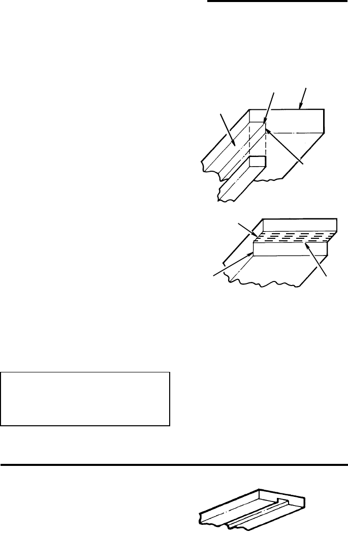
52
Basic Saw Operations (continued)
Rabbeting
Rabbeting is known as cutting out a sec-
tion of the corner of a piece of material,
across an end or along an edge.
To make a rabbet requires cuts which do
not go all the way through the material.
Therefore, the blade guard must be
removed.
1. Remove blade guard.
2. For rabbeting along an edge (long way
of workpiece) as shown add facing to
rip fence approximately as high as the
workpiece is wide. Adjust rip fence and
blade to required dimensions; then
make first cut with board flat on table as
any rip (type) cut; make second cut with
workpiece on edge. Follow all precau-
tions, safety instructions, and opera-
tional instructions as for ripping, or rip
type operations, including feather-
boards and push stick, etc.
3. For rabbeting across an end, for work-
piece 10-1/2” and narrower, make the
rabbet cut with the board flat on the
table. Using the miter gauge fitted with
a facing, follow the same procedures
and instructions for cross cutting mak-
ing successive cuts across the width of
the workpiece to obtain the desired
width of cut. Do not use the rip fence for
rabbeting across the end.
WARNING: For your own safety,
install blade guard immediately
upon completion of rabbeting
operation.
Some rabbet cuts can also be made in
one pass of the workpiece over the cutter
using a dado head.
Ploughing and Molding
Ploughing is grooving with the grain the
long way of the workpiece, using the
fence. Use featherboards and push sticks
as required.
Rabbet
Second Cut
First Cut
This Side
Against Fence
When Making
Second Cut
Rabbet
Second
First
Cut Etc.
Cut
Ploughing
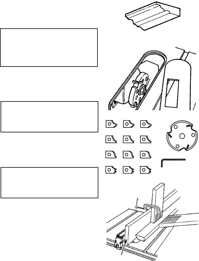
53
Molding
Molding is cutting a shape on the edge or
face of the workpiece. With a molding
head and a selection of different knife
shapes it is possible for almost any kind of
molding (base, cove, bead, etc.) to be
produced.
There are a wide variety of molding heads
available as well as many different
shapes of knives. Be sure and consult the
specific instructions included with your
molding head.
WARNING: For your own safety;
always read, understand, and fol-
low all directions in the instruc-
tional booklet furnished with the
molding head.
The slot provided for the sawblade in the
regular table insert is too small for the
molding head to pass through. Therefore,
a special dado/molding insert must be
purchased.
WARNING: For your own safety,
always use molding insert listed
under recommended accesso-
ries.
When using the molding head it will be
necessary to remove the blade guard and
spreader. Use caution. Use miter gauge,
fence, featherboards, push sticks or fence
facing board, etc., as required.
WARNING: For your own safety,
always replace the blade, table
insert, guard and spreader when
you are finished molding.
A typical molding head is shown, The var-
ious shapes of knives are fitted into
grooves in the cutterhead and secured
with a screw(s).
The molding head is assembled to the
saw arbor in the same manner as the saw
blade. It is not necessary to install the out-
side loose collar before screwing on the
arbor nut. Make sure the arbor nut is tight.
It is necessary to use an auxiliary fence
when shaping edges of a workpiece.
Position the auxiliary fence over the cut-
terhead with the cutter head below the
surface of the saw table. Turn the saw
“ON” and slowly raise the cutterhead. The
cutterhead will then cut its own groove in
the auxiliary fence.
Molding
Auxiliary Fence
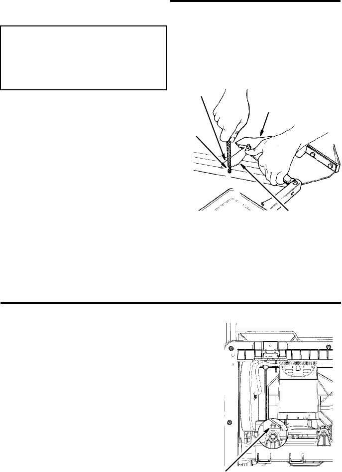
54
Maintaining Your Table Saw
Maintenance
WARNING: For your own safety,
turn switch “OFF” and remove
plug from power source outlet
before maintaining or lubricating
your saw.
• Do not allow sawdust to accumulate
inside the saw. Frequently blow out any
dust that may accumulate inside the
saw cabinet and the motor.
• Clean your cutting tools with a gum and
pitch remover.
• The cord and the tool should be wiped
with a dry clean cloth to prevent deteri-
oration from oil and grease.
• A coat of furniture paste wax applied to
the table will help to keep the surface
clean and allow workpieces to slide
more freely.
• If the power cord is worn, cut, or dam-
aged in any way, have it replaced
immediately.
Anti-Kickback Pawls
Make sure the teeth of the anti-kickback
pawls are always sharp. To sharpen:
1. Remove blade guard.
2.Rotate pawl toward rear of spreader so
that teeth are above top of spreader.
3.Hold spreader with left hand and place
pawl over corner of workbench as
shown.
4.Using a small round file (smooth cut)
sharpen the teeth.
5. Reinstall blade guard.
Adjusting Nylon Set Screw
If the sawblade has a very slight amount
of lateral movement (left-right movement),
or if the sawblade is elevated and tends to
lower itself slightly, the nylon set screw
needs to be tightened.
1. Bevel the sawblade to 45°.
2. Locate the 10-32 x 3/4 nylon set screw
and nut. Reference service key #27 &
28 page 48. See illustration.
3. Turn the nut counterclockwise to
loosen.
4. Tighten the set screw.
5. Retighten the nut.
6. Bevel the sawblade back to 90°.
Anti-Kickback
Pawl
Round
File
Teeth
Spreader
Nylon Screw
and Nut
Bottom View of Saw
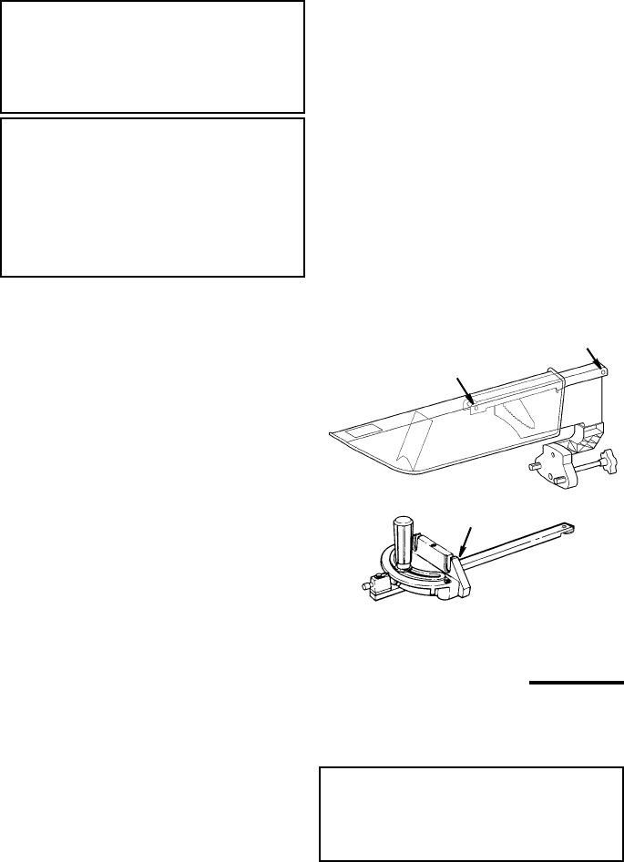
RR
t^okfkdW=qç=êÉÇìÅÉ=íÜÉ=êáëâ=çÑ=
áåàìêó=Ñêçã=ìåÉñéÉÅíÉÇ=ëí~êíáåÖ=
çê=ÉäÉÅíêáÅ~ä=ëÜçÅâI=ìåéäìÖ=íÜÉ=
éçïÉê=ÅçêÇ=ÄÉÑçêÉ=ïçêâáåÖ=çå=
íÜÉ=ë~ïK
t^okfkdW=qç=êÉÇìÅÉ=íÜÉ=êáëâ=çÑ=
ÉäÉÅíêáÅ~ä=ëÜçÅâI=ÑáêÉ=çê=áåàìêóI=
ìëÉ=çåäó=é~êíë=áÇÉåíáÅ~ä=íç=íÜçëÉ=
áÇÉåíáÑáÉÇ=áå=íÜÉ=é~êíë=äáëí=êÉ~ëJ
ëÉãÄäÉ=Éñ~Åíäó=~ë=çêáÖáå~ä=
~ëëÉãÄäó=íç=êÉÇìÅÉ=íÜÉ=êáëâ=çÑ=
ÉäÉÅíêáÅ~ä=Ü~ò~êÇëK
oÉéä~ÅáåÖ=`~êÄçå=_êìëÜÉë
qÜÉ=Å~êÄçå=ÄêìëÜÉë=ÑìêåáëÜÉÇ=ïáää=ä~ëí=
~ééêçñáã~íÉäó=RM=Üçìêë=çÑ=êìååáåÖ=íáãÉ=çê=
NMIMMM=çåLçÑÑ=ÅóÅäÉëK=qç=áåëéÉÅí=çê=
êÉéä~ÅÉI=Ñáêëí=ìåéäìÖ=íÜÉ=ë~ïK=içïÉê=
Ää~ÇÉ=~ää=íÜÉ=ï~óI=ÄÉîÉä=íç=QRø=~åÇ=äçÅâK=
qìêå=ë~ï=ìéëáÇÉ=ÇçïåK=oÉãçîÉ=ÄêìëÜ=Å~é=
ïáíÜ=~=ëÅêÉïÇêáîÉêK=_êìëÜ=~ëëÉãÄäó=áë=
ëéêáåÖ=äç~ÇÉÇ=~åÇ=ïáää=éçé=çìí=ïÜÉå=óçì=
êÉãçîÉ=íÜÉ=ÄêìëÜ=Å~éK=oÉãçîÉ=ÄêìëÜ=
~ëëÉãÄäó=~åÇ=ÅÜÉÅâ=Ñçê=ïÉ~êK=oÉéä~ÅÉ=
ÄçíÜ=ÄêìëÜÉë=ïÜÉå=ÉáíÜÉê=Ü~ë=äÉëë=íÜ~å====
NLQ?=äÉåÖíÜ=çÑ=Å~êÄçå=êÉã~áåáåÖK=aç=åçí=
êÉéä~ÅÉ=çåÉ=ëáÇÉ=ïáíÜçìí=êÉéä~ÅáåÖ=íÜÉ=
çíÜÉêK=oÉ~ëëÉãÄäÉ=ìëáåÖ=åÉï=ÄêìëÜ=
~ëëÉãÄäáÉëK=j~âÉ=ëìêÉ=Åìêî~íìêÉ=çÑ=ÄêìëÜ=
ã~íÅÜÉë=Åìêî~íìêÉ=çÑ=ãçíçê=~åÇ=íÜ~í=
ÄêìëÜ=ãçîÉë=ÑêÉÉäó=áå=ÄêìëÜ=íìÄÉK=j~âÉ=
ëìêÉ=ÄêìëÜ=Å~é=áë=çêáÉåíÉÇ=ÅçêêÉÅíäó=
Eëíê~áÖÜíF=~åÇ=êÉéä~ÅÉK=qáÖÜíÉå=ÄêìëÜ=Å~é=
ëÉÅìêÉäóK=aç=åçí=çîÉêíáÖÜíÉåK
iìÄêáÅ~íáçå
qÜÉ=ë~ï=ãçíçê=ÄÉ~êáåÖë=~åÇ=ÖÉ~ê=Å~ëÉ=
Ü~îÉ=ÄÉÉå=é~ÅâÉÇ=~í=íÜÉ=Ñ~Åíçêó=ïáíÜ=
éêçéÉê=äìÄêáÅ~åí=~åÇ=êÉèìáêÉ=åç=~ÇÇáíáçå~ä=
äìÄêáÅ~íáçåK=qÜÉ=ÑçääçïáåÖ=é~êíë=ëÜçìäÇ=ÄÉ=
çáäÉÇ=çÅÅ~ëáçå~ääó=ïáíÜ=p^b=åçK=OM=çê=åçK=
PM=ÉåÖáåÉ=çáäK
NK bäÉî~íáçå=ëÅêÉï=íÜêÉ~ÇëK=Ecáêëí=ÅäÉ~å=
ïáíÜ=~=ëçäîÉåí=êÉÅçããÉåÇÉÇ=Ñçê=Öìã=
~åÇ=éáíÅÜ=êÉãçî~äFK
OK _É~êáåÖ=éçáåíë=áå=Ää~ÇÉ=Öì~êÇ=~åÇ=ãáíÉê=
Ö~ìÖÉK
ofadfa=oÉÅçããÉåÇë=íÜÉ=cçääçïáåÖ=^ÅÅÉëëçêáÉë
fíÉã phr=kçK
q~ÄäÉ=p~ï=jáíÉê=d~ìÖÉ
eçäÇ=açïå=`ä~ãé KKKKKKKKKKKKKKKKKKKKKKK ^`NMOO
a~ÇçLjçäÇáåÖ=fåëÉêíKKKKKKKKKKKKKKKKKKKK ^`NMQM
wÉêç=`äÉ~ê~åÅÉ=fåëÉêí KKKKKKKKKKKKKKKKKK ^`NMQR
råáîÉêë~ä=mçïÉê=qççä=iÉÖëÉí KKKKKKK ^`VVNM
aç=åçí=ìëÉ=~åó=~ÅÅÉëëçêó=ìåäÉëë=óçì=
Ü~îÉ=êÉÅÉáîÉÇ=~åÇ=êÉ~Ç=ÅçãéäÉíÉ=áåëíêìÅJ
íáçåë=Ñçê=áíë=ìëÉK
klqbW=^`NMORI=^`NMPM=~åÇ=^`NMPR=
_ä~ÇÉ=fåëÉêíë=~êÉ=åçí=Åçãé~íáÄäÉ=ïáíÜ=íÜáë=
ë~ïK
t^okfkdW=rëÉ=çåäó=~ÅÅÉëëçêáÉë=
êÉÅçããÉåÇÉÇ=Ñçê=íÜáë=ë~ïK=
rëáåÖ=çíÜÉê=~ÅÅÉëëçêáÉë=ã~ó=ÄÉ=
Ç~åÖÉêçìëK
2
2
2

56
Troubleshooting
WARNING: For your own protection, turn switch “OFF” and always
remove plug from power source outlet before troubleshooting.
General
Trouble Probable Cause Remedy
Excessive
Vibration 1. Blade out of balance or
damaged 1. Replace blade.
Cannot make
square cut when
crosscutting.
1. Miter gauge not
adjusted properly. 1. See “Adjustments” section “Miter
Gauge.”
Cut binds, burns
or stalls motor
when ripping.
1. Dull blade or improper
tooth set.
2. Blade is heeling.
3. Warped board
4. Rip fence not parallel
to blade.
5. Spreader out of align-
ment.
1. Sharpen or replace blade.
2. See “Alignment” section, “Heeling
Adjustment”.
3. Make sure concave or hollow side is
facing “down” feed slowly.
4. See “Alignment” section, “Aligning
Rip Fence.”
5. See “Alignment” section, “Installing
Blade Guard.”
Cut not true at
90° or 45° bevel
positions.
1. Indexes not properly
adjusted.
1. See “Alignment” section, “Blade Tilt,
or Squareness of Blade to Table”.
Elevating hand-
wheel turns
hard.
1. Sawdust on threads of
elevating screw.
1. See “Maintenance” and “Lubrication”
sections.

57
Motor
NOTE: Motors used on wood working tools are particularly susceptible to the accumu-
lation of sawdust and wood chips and should be blown out or “Vacuumed” frequently to
prevent interference with normal motor ventilation.
Trouble Probable Cause Remedy
Excessive Noise 1. Motor 1. Have motor checked by qualified
service technician. Repair ser-
vice is available at your nearest
Authorized Service Center.
Motor fails to
develop full
power. NOTE:
Low Voltage:
(Power output of
motor decreases
rapidly with
decrease in volt-
age at motor ter-
minals.
1. Circuit overloaded with lights,
appliances and other motors.
2. Wiring circuit (extension cord)
too long or undersize.
3. General overloading of power
company facilities. (In some
sections of the country,
demand for electrical power
may exceed the capacity of
existing generating and distri-
bution systems.)
4. Incorrect fuses or circuit
breakers in power line.
1. Do not use other appliances or
motors on same circuit when
using the saw.
2. Increase wire sizes, or reduce
length of circuit. See “Motor
Specifications and electrical
Requirements” section.
3. Request a voltage check from
the power company.
4. Install correct fuses or circuit
breakers.
Motor starts
slowly or fails to
come up to full
speed
1. Low voltage.
2. Windings burned out or open.
1. Request voltage check from the
power company.
2. Have motor repaired or replaced.
Motor overheats 1. Motor overloaded
2. Improper cooling. (Air circula-
tion restricted through motor
due to sawdust, accumulating
inside of saw.)
1. Feed work slower into blade.
2. Clean out sawdust to provide
normal air circulation through
motor. See “Maintenance” and
“Lubrication” section.
Motor stalls
(resulting in
blown fuses or
tripped circuit
breakers)
1. Voltage too low to permit
motor to reach operating
speed.
2. Fuses or circuit breakers do
not have sufficient capacity.
1. Request voltage check from the
power company.
2. Install proper size fuses or circuit
breakers.
Frequent open-
ing of fuses or
circuit breakers
1. Motor overloaded
2. Fuses or circuit breakers do
not have sufficient capacity.
1. Feed work slower into blade.
2. Install proper size fuses or circuit
breakers.
Motor runs inter-
mittently, sparks
excessively or
fails to start
1. Worn or damaged brushes 1. Replace brushes. See “Mainte-
nance” section.
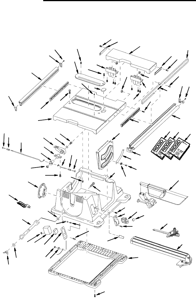
58
Repair Parts
Parts List for RIDGID 10 Inch Table Saw
Model No. TS24001
RIDGID parts are available on-line at www.ridgidparts.com
Figure 1
123
60 6
9
17
38
21
23
24
22
26
27
28 31
41
32
34
35
37
36
39
25
7
8
15
40
20
16
43
45
55
21
5
5
12
29
33
4
30
42
50
46
44 5152
53
54
47
48
49
44 43
56
13
11
61
57
58
59
See Figure 5
See Figure 3
See Figure 4
63 64
62
1
13
14
65
11
4
10
18
19
68
67
66

59
Repair Parts
Parts List for RIDGID 10 Inch Table Saw
Model No. TS24001
RIDGID parts are available on-line at www.ridgidparts.com
Figure 1
Always Order by Part Number - not by Key Number
* Standard Hardware Item - May be purchased locally
† These parts are available where you purchased your saw.
Key
No. Part No. Description
1
2
3
4
5
6
7
8
9
10
11
12
13
14
15
16
17
18
19
20
21
22
23
24
25
26
27
28
29
30
31
32
33
34
35
126317
827518
827545
73352
827478
159572-146
830397
809813-1
827872
104879
827533
830345
448013
830378
830396
827497
827870
808380-2
829971-8
9420474
826395
AC1000
808380-18
808275-4
827493
808380-5
830399
805475
830398
169123-2
138164
827925
827873
827921
827548
* Bolt Carriage 1/4-20 x 1
Mount Rail Extension
Table Extension
* Nut Hex Flange 1/4-20
Clip Fence
* Screw Hex Wash Hd Ty T
10-32 x 7/8
Scale Rip
Screw Pan Rec 6-32 x 1/2
Spring Rip Scale
Screw Lock Set 10-32x3/16
Slider Rail
Cap Rail Front Right
* Screw Pan Hd Ty Ab N8x1/2
Rail Front
Cap Rail Front Left
Panel Front
Scale Bevel
* Screw Pan Hd #8 x 3/8
Base w/Labels
* Screw Hex Wash Hd Ty T
10-32 x 1/2
Bezel Switch
†Key Switch
Screw Pan Hd #6 x 3/4
Plastite
* Screw Pan Hd 8-32 x 3/8
Foot Base
* Screw Pan Hd #8 Plastite
Plate Switch Box
* Nut Hex 8-32
Box Switch
Relief Strain
* Lockwasher #8
Bolt Carriage 1/2-13 x 1-1/2
Nut Push 1/2
Washer Flat Nylon
Wrench Arbor
Key
No. Part No. Description
36
37
38
39
40
41
42
43
44
45
46
47
48
49
50
51
52
53
54
55
56
57
58
59
60
61
62
63
64
65
66
67
68
827874
808380-17
805550-5
830405
830406
274622
821521
827463
827482
827515
827523
827515-1
830377
827514
274205
805552
813051-5
830376
827645
827525
827470
509492
809374
826390
805297-12
138671
826347
829971-7
829971-6
805549-22
SP6499
SP6499S
SP6499F
Nut Wing Nylon 1/2-13
* Screw Pan Hd #10 x 3/4
Plastite
Washer 7/32 x 5/8 x 1/16
Cord w/Plug
Wrap Cord
Screw Hex Hd Ty T
1/4-20 x 1
Screw Hex Hd Shoulder .312
Bolt T 1/4-20
Coupling 1/4-20
Link Locking Front
Pivot Linkage
Link Locking Rear
Bearing Rail Lock
Lever Table Lock
Nut Lock 1/4-20
* Washer 17/64 x5/8 x 1/16
* Screw Pan Hd 1/4-20 x 2-3/4
Table Main
Cap Rear Rail Left
Rail Rear
Cap Rear Rail Right
Insert Asm
Screw Flat Hd 10-32 x 1
Insert Ind-I-Cut
Screw Soc Flat Hd
5/16-18 x 1
Screw Set 5/16-18 x 5/8
Switch Locking
Circuit Asm
Switch Reset Asm
Washer #10
13/64 x 3/8 x .031
Owners Manual - English
Owners Manual - Spanish
Owners Manual - French
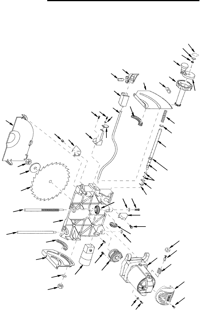
60
Repair Parts
Parts list for RIDGID 10 Inch Table Saw
Model No. TS24001
RIDGID parts are available on-line at www.ridgidparts.com
Figure 2
1
8
910 11
12
13
14 51
16 49
18
19
20
21
22
23
2425
26
27
28
29 30 31
32
33
2
3
45
67
47
23
42
34
35
36
37
38
39 40 41
52
4546
18
43
24
15
50
48
21 21
17
44

61
Repair Parts
Parts List for RIDGID 10 Inch Table Saw
Model TS24001
RIDGID parts are available on-line at www.ridgidparts.com
Figure 2
Always Order by Part Number - not by Key Number
* Standard Hardware Item - May be purchased locally
Key
No. Part No. Description
1
2
3
4
5
6
7
8
9
10
11
12
13
14
15
16
17
18
19
20
21
22
23
24
25
26
827483
370625
827619
827540
141594-46
824334-1
805550-5
808380-17
827459
827862
827522
827500
827519
830390
830391
37937
809372-7
827467
829971-9
821421-11
805561-4
805641-4
60136
827496
802612-8
830381
Cover Blade
* Screw Hex Wash Hd
1/4-20 x 1/2
Plate Bevel Stop
Support Bevel Indicator
* Screw Soc Cap
1/4-20 x 5/8
Indicator
* Washer 7/32 x 5/8 x 1/16
* Screw Pan Hd #10 x 3/4
Bar Locking
Clamp Asm Bevel
Pivot Bevel Lock
Handle Bevel Lock
Mount Front
Knob Asm Bevel
Handle Asm Elevation
* Washer 17/64 x 5/8 x 1/32
* Screw Pan Hd 10-32 x 5/8
Bushing Trunnion
Shaft Elevation Crank
(Includes “O” Rings)
Ring “O” 3/8 x 1/16
Washer .505 x 3/16 x 1/32
Ring Retaining 5133-50
* Washer 13/64 x 5/8 x 1/32
Gear Elevation
Nut Push 3/8
Motor Asm
Key
No. Part No. Description
27
28
29
30
31
32
33
34
35
36
37
38
39
40
41
42
43
44
45
46
47
48
49
50
51
52
827863
827864
830412
9420474
808380-17
827476
60249
60014
827520
827531
830380
827529
830394
827465
6362
830386
816768
826017
828064
828122-1
809398
830385
60415
830393
830392
830250
Screw Set Nylon
10-32 x 3/4
Nut Hex Nylon 10-32
Arbor Asm
*Screw Hex Ty T
10/32 x 1/2
* Screw Pan Hd #10 x 3/4
Chute Sawdust
* Nut Lock 3/8-16
* Washer
.380 x 47/64 x 3/32
Mount Rear
Shaft Guide
Cradle
Shaft Elevation
Blade 10" 24T Carb.
Collar Blade
Nut Arbor
Spring
Brush
Holder Brush
Cover Motor Rear
Screw Wash Hd Cr M4-10
Nut Weld
Spacer Elev Lock
Washer Spring
Knob Elevation Lock
Knob Swivel
Cover, Brush
62
Repair Parts
Parts List for RIDGID 10 Inch Table Saw
Model No. TS24001
RIDGID parts are available on-line at www.ridgidparts.com
Figure 3 - Miter Gauge Assembly
Always Order by Part Number - Not by Key Number
* Standard Hardware Item - May be purchased locally
Key
No. Part No. Description
–
1
2
3
4
5
6
7
8
9
10
11
12
13
14
15
16
830338
826506-1
821063-5
826663
824723-1
123069-1
830351
830352
140755-15
824723
818470-4
830350
830354
830353
134530
809813-4
818471-6
Miter Gauge Asm. Complete
Knob
* Washer 8 x 23 x 1.8
Gauge, Miter
* Screw, Pan Hd. 8/32 x 5/16
Indicator
Block, Miter Gauge Indicator
Pin, Miter
* Lockwasher #8
* Screw, Pan Hd 8-32 x 5/8
Screw Flat Hd. M6 x 1.0-16
Rod, Miter Gauge
Screw, Flat Head
Washer, “T” Slot
* Nut Hex 6-32
Screw Pan Hd. 6-32 x 5/8
Screw, Set 5 x 0.8-5
1
2
3
4
5
6
7
8
9
10
11
12
13 14
16
15
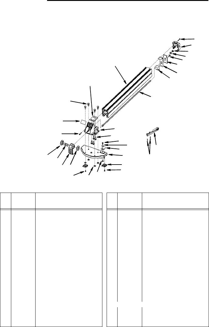
63
Repair Parts
Parts List for RIDGID 10 Inch Table Saw
Model No. TS24001
RIDGID parts are available on-line at www.ridgidparts.com
Figure 4 - Fence Assembly
Always Order by Part Number - not by Key Number
* Standard Hardware Item - May be purchased locally
2
3
4
5
6
7
8
9
10
11 12
13
15
16
17
18
19
20
21
22
23
17
25
24
1
20 27
1
14
26
28
Key
No. Part No. Description
–
1
2
3
4
5
6
7
8
9
10
11
12
13
14
15
16
830421
809492-5
824350-1
820129
274865
9416390
824328-1
824332
824349-1
824342-1
827507
9422329
809372-3
60136
830281
830426
827532
Fence Complete
Screw Pan Hd. Ty “T” 8-32x1
Cap Channel Rear
* Nut Lock 5/16-18
* Washer 21/64 x 5/8 x 1/16
* Screw Pan Hd. Ty “T”
10-32 x 5/8
Plate Lock
Spring Lock
Slide Rear Fence
Rod Fence Lock
Housing Rip Fence
* Scr Hex Hd TY “T”
1/4-20 x 3/4
* Screw Pan 10-32 x 1/2
* Washer 13/64 x 5/8 x 1/32
Indicator
Head Rip Fence
Slide Fence Head
Key
No. Part No. Description
17
18
19
20
21
22
23
24
25
26
27
28
809169-3
822138-1
62636
824326
830425
824329
827876
828173
824330-1
829971-10
806752-2
829706
159653-3
805552
115120
*Screw Pan Hd. Ty “T”
8-32 x 3/8
* Nut Sq 10-32
* Nut Sq 1/4-20
Bearing Ball Angular Contact
Lever Cam Fence
Pin Cam
Label RIDGID
* Screw Hex Washer Hd.
1/4-20 x 3/4
Plate Fence Channel
Channel Fence
Screw Pan Hd Ty “T”
10-32 x 1-1/4
Micro Adjust Asm
Bolt Sq. Hd. 1/4-20 x 3/4
* Washer 17/64 x 5/8 x 1/16
* Nut Hex 1/4-20
Hardware for Attaching Wood Facing
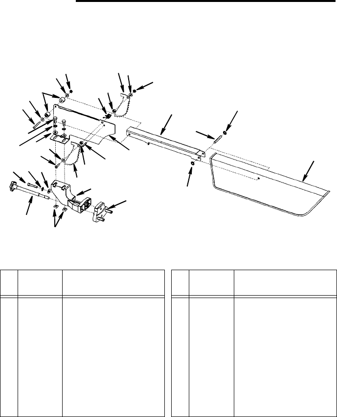
64
Repair Parts
Parts List for RIDGID 10 Inch Table Saw
Model No. TS24001
RIDGID parts are available on-line at www.ridgidparts.com
Figure 5 - Guard Assembly
Always Order by Part Number - not by Key Number
* Standard Hardware Item - May be purchased locally
12
34
5
8
11
12
7
10
6
9
8
13
15
16 17
21
22
2
3
14
4
19
45
4
17
18
18
20
Key
No. Part No. Description
–
1
2
3
4
5
6
7
8
9
10
827499
62519
827646
827648-1
805549
60012
827649-1
62390
802612
826466
827536
Guard Complete
Spring, Pawl
Spacer, Pawl
Pawl
*Washer,
13/64 x 9/16 x 1/32
Nut Lock 10-32
Support, Guard
Pin Guard 1/4 x 1-3/4
Nut Push 1/4
Guard w/Label
Spreader Blade
Key
No. Part No. Description
11
12
13
14
15
16
17
18
19
20
21
22
803422-163
827541
827877
62636
827511
805461-7
114604
37937
806214-3
179793
806214-4
827647
Pin, Roll 3/16 x 15/16
Support Spreader
Mount Spreader
Nut Square 1/4-20
Knob Guard
Screw Hex Hd 1/4-20 x 1
* Lockwasher Ext 1/4
* Washer 17/64 x 5/8 x 1/32
Screw Soc Cap 10-32 x 7/8
* Screw Hex Hd 1/4-20 x 5/8
Screw Soc Cap 10-32x1-1/2
Spacer Support

65
Notes

66
Notes

67
Notes

QUESTIONS OR COMMENTS?
CALL 1-866-539-1710
www.ridgidwoodworking.com
Please have your Model Number and Serial
Number on hand when calling.
© 2003 RIDGID, INC.
This product is manufactured under license from Ridgid, Inc. by One World
Technologies, Inc.. All warranty communications should be directed to One
World Technologies, Inc. at (toll free) 1-866-539-1710.
90-Day Satisfaction GuaranteePolicy
During the first 90 days after the date of purchase, if you are dissatisfied
with the performance of this Ridgid® tool for any reason, you may return
the tool to the dealer from which it was purchased for a full refund or
exchange. To receive a replacement tool you must present proof of pur-
chase and return all original equipment packaged with the original product.
The replacement tool will be covered by the limited warranty for the bal-
ance of the three year warranty period.
What is covered under the Limited Three Year Warranty
This warranty covers all defects in workmanship or materials in this
RIDGID® tool for the three year period from the date of purchase. This war-
ranty is specific to this tool. Warranties for other RIDGID® products may
vary.
How to obtain service
To obtain service for this RIDGID® tool you must return it, freight prepaid, to
an authorized RIDGID® service center for hand held and stationary power
tools. You may obtain the location of the authorized service center nearest
you by calling (toll free) 1-866-539-1710 or by logging on to the RIDGID®
website at www.ridgidwoodworking.com. When requesting warranty ser-
vice, you must present the proof of purchase documentation, which
includes a date of purchase. The authorized service center will repair any
faulty workmanship, and either repair or replace any defective part, at our
optioon at no charge to you.
What is not covered
This warranty applies only to the original purchaser at retail and may not be
transferred. This warranty only covers defects arising under normal usage
and does not cover any malfunction, failure or defect resulting from misuse,
abuse, neglect, alteration, modification or repair by other than authorized
RIDGID® service center for hand held and stationary power tools. One
World Technoligies, Inc. makes no warranties, representations or promises
as to the quality or performance of its power tools other than those specifi-
cally stated in this warranty.
Additional Limitations
To the extent permitted by applicable law, all implied warranties, including
warranties of MERCHANTABILITY or FITNESS FOR A PARTICULAR PUR-
POSE, are disclaimed. Any implied warranties, including warranties of mer-
chantability or fitness for a particular purpose, that cannot be disclaimed
under state law are limited to three years from the date of purchase. One
World Technologies, Inc. is not responsible for direct, indirect, incidental or
consequential damages. Some states do not allow limitations on how long
an implied warranty lasts and/or do not allow the exclusion or limitation of
incidental or consequential damages, so the above limitations may not
apply to you. This warranty gives you specific legal rights, and you may
also have other rights which vary from state to state.
RIDGID® HAND HELD AND STATIONARY POWER TOOL
LIMITED THREE YEAR WARRANTY AND
90 DAY SATISFACTION GUARANTEE POLICY
Part No. SP6499 Form No. SP6499 Printed in Taiwan 5/05
Stock No. TS2400
Model No. TS24001 Serial No. ________
Model and serial numbers may be found on the left rear
side of the base.You should record both model and serial
number in a safe place for future use.
