Ridgid Wts2000L Operators Manual 820303 ManualsLib Makes It Easy To Find Manuals Online! User
2016-05-05
User Manual: Ridgid Ridgid-Wts2000L-Operators-Manual-820303
Open the PDF directly: View PDF ![]() .
.
Page Count: 44

OPER
A
TOR’S
MANUAL
10 INCH WET TILE/STONE SAW
WITH LASER GUIDE, LED WORK LIGHT,
AND STAND
WTS2000L
W
ARNING:
To reduce the risk of injury, the user must read and understand the operator’s manual before using this product.
Thank you for buying a RIDGID product.
SAVE THIS MANUAL FOR FUTURE REFERENCE

2
TABLE OF CONTENTS
n General Safety Instructions ........................................................................ 3
Safety Symbols ................................................................................... 3
Work-Area Safety ................................................................................. 3
Electrical Safety .................................................................................. 3
Personal Safety ...................................................................................4
Tool Safety ...................................................................................... 5
Service Safety .................................................................................... 5
n Specific Safety Instructions for RIDGID Wet Tile/Stone Saw ............................................ 6
Safety Instructions for Wet Tile/Stone Saw ............................................................6-7
Safety Instructions for Laser ......................................................................... 8
n Glossary of Terms ................................................................................ 9
n Motor Specification and Electrical Requirements ..................................................... 9
Power Supply and Motor Specication ................................................................ 9
Motor Overload Protector .......................................................................... 10
Wire Sizes ......................................................................................10
n Unpacking and Checking Contents ................................................................ 11
Unpacking ...................................................................................... 11
List of Loose Parts ............................................................................... 11
List of Main Parts ................................................................................ 12
n Assembly ...................................................................................... 13
Stand Set Up ................................................................................ 13-14
Installing the Motor Assembly ...................................................................... 15
Installing the Water Pump. . . . . . . . . . . . . . . . . . . . . . . . . . . . . . . . . . . . . . . . . . . . . . . . . . . . . . . . . . . . . . . . . . . . . . . 15-16
Mounting Your Saw .............................................................................. 17
Installing the Extension Table ....................................................................... 18
Installing the Extension Water Tray. . . . . . . . . . . . . . . . . . . . . . . . . . . . . . . . . . . . . . . . . . . . . . . . . . . . . . . . . . . . . . . . . . . 18
Installing the Saw Blade .........................................................................19-20
Installing the Universal Guide .......................................................................20
n Getting to Know Your Wet Tile/Stone Saw ........................................................21-24
Technical Specications ...........................................................................24
n Adjustments ................................................................................... 25
Depth Adjustment ................................................................................ 25
Depth-Stop Adjustment ........................................................................... 25
Bevel-Cut Adjustment ............................................................................ 26
Work Table Stop/Go Adjustment .................................................................... 26
Universal Guide Adjustment ........................................................................27
Laser Beam Calibration ........................................................................... 28
Rail Adjustment ..................................................................................29
n Operation ...................................................................................... 30
Safety Instructions for Basic Operations ............................................................30-31
Filling and Draining the Water Tray ................................................................... 31
Power Supply ................................................................................... 31
Cutting Tile and Stone ............................................................................ 32
Straight Cut ..................................................................................... 32
Flat 0°- 45° Angle Cut ............................................................................. 32
Bevel Cut ...................................................................................... 33
Plunge Cut ..................................................................................... 33
Moving the Saw ................................................................................. 34
n Maintaining Your Saw ............................................................................ 35
Maintenance .................................................................................... 35
Cleaning the Water Pump .......................................................................... 35
Changing Carbon Brushes .........................................................................35
n Attachments ................................................................................... 36
n Troubleshooting ................................................................................ 36
n Exploded Drawings and Parts List ...............................................................37-40
n Warranty. . . . . . . . . . . . . . . . . . . . . . . . . . . . . . . . . . . . . . . . . . . . . . . . . . . . . . . . . . . . . . . . . . . . . . . . . . . . . . . . . . . . . . . 44

3
WARNING:
Some dust created by using power tools contains chem-
icals known to the state of California to cause cancer
and birth defects or other reproductive harm.
Safety is a combination of using common sense, staying
alert, and knowing how your tile saw works. Read this man-
ual to understand this tile saw and how to use it safely.
Safety Symbols
The purpose of safety symbols is to attract your attention to
possible dangers. The safety symbols and the explanations
that accompany them deserve your careful attention and
understanding. The safety warnings DO NOT, by them-
selves, eliminate any danger. They are no substitutes for
proper accident-prevention measures.
DANGER:
Someone will be seriously injured or killed if the safety
information is not followed.
WARNING:
Someone could be seriously injured or killed if the safe-
ty information is not followed.
CAUTION:
Someone may be injured if the safety information is not
followed.
Damage Prevention and Information Messages
These inform the user of import information and/or instruc-
tions that could lead to equipment or other property dam-
age if they are not followed. Each message is preceded by
the word “NOTE,” as in the example below:
NOTE: Equipment and/or property damage may result if
these instructions are not followed.
Work-Area Safety
• KEEP THE WORK AREA CLEAN AND WELL LIT. Clut-
tered benches and dark areas invite accidents.
• DON’T USE IN A DANGEROUS ENVIRONMENT. Don’t
use power tools in damp or wet locations or expose them
to rain. Don’t operate power tools in potentially explosive
environments, such as in the presence of ammable
liquids, gases, or dust. Power tools create sparks, which
may ignite the dust or fumes.
• OPERATE THE TOOL IN WELL-VENTILATED AREAS,
and provide proper dust removal. Dust generated from
some materials can be hazardous to your health. Use
dust-collection systems whenever possible.
• KEEP CHILDREN AND BYSTANDERS AWAY. All visi-
tors should be kept a safe distance away from the work
area.
• USE THE RIGHT TOOL. Don’t force a tool or attachment
to do a job for which it was not designed.
• MAKE THE WORKSHOP CHILD-PROOF with padlocks,
master switches, or by removing starter keys.
Electrical Safety
WARNING:
To reduce the risk of electrocution, keep all connections
dry and off the ground. Do not touch the plug with wet
hands.
• VOLTAGE: Before plugging in the tool, make sure that the
outlet voltage is within the voltage marked on the tool's
data plate.
• DO NOT USE “AC ONLY” RATED TOOLS WITH A DC
POWER SUPPLY.
• DO NOT EXPOSE POWER TOOLS TO RAIN OR WET
CONDITIONS. Water entering a power tool will increase
the risk of electric shock.
• If operating the power tool in damp locations is unavoid-
able, always use a Ground Fault Circuit Interrupter to sup-
ply power to your tool. Always wear electrician's rubber
gloves and footwear in damp conditions.
• DO NOT ABUSE THE CORD. Never use the cord to carry
the tools or to pull the plug from the outlet. Keep the cord
away from heat, oil, sharp edges, or moving parts. Replace
damaged cords immediately. Damaged cords increase
the risk of electric shock.
• USE THE PROPER EXTENSION CORD.
Extension Cords
Use only extension cords that are intended for outdoor use.
These extension cords are identied by a marking “Accept-
able for use with outdoor appliances, store indoors while not
in use.”
Use only extension cords having an electrical rating equal
to or greater than the rating of the product. Do not use dam-
aged extension cords. Examine the cord before using, and
replace it if it is damaged. Do not abuse extension cords,
and do not yank on any cord to disconnect it. Keep the cord
away from heat and sharp edges. Always disconnect the
extension cord from the receptacle before disconnecting
the product from the extension cord.
• Make sure that your extension cord is in good condition.
• When using an extension cord, be sure to use one that is
heavy enough to carry the current your product will draw.
An Undersized cord will cause a drop in line voltage result-
ing in loss of power and overheating.
GENERAL SAFETY INSTRUCTIONS
4
• Table 1 shows the correct size to use depending on cord
length and ampere rating. If in doubt, use the next heavier
gauge: the smaller the gauge number, the heavier the cord.
• When operating a power tool outdoors, ALWAYS use an
outdoor extension cord marked “W-A” or “W.” These
cords are rated for outdoor use and reduce the risk of
electric shock.
• Use only 3-wire extension cords that have 3-prong ground-
ing plugs and 3-pole receptacles that accept the tool’s plug.
Ampere
Rating
Volts Total Length of Cord in Feet
120 V~
25 ft. 50 ft. 100 ft. 150 ft.
A. W. G.
0~6 18 16 16 14
6~10 18 16 14 12
10~12 16 16 14 12
12~16 14 12 Not
Recommended
Table 1
Ground Instruction
All Grounded, Cord-Connected Tools:
• In the event of a malfunction or breakdown, grounding
provides a path of least resistance for the electric current
to reduce the risk of electrical shock. This tool has an elec-
tric cord with an equipment-grounding conductor and a
grounding plug. The plug must be plugged into a match-
ing outlet that is properly installed and grounded in accor-
dance with all local codes and ordinances.
• Do not modify the plug provided with this tool. If it will not
t the outlet, have a properly grounded outlet installed by
a qualied electrician.
• Improper connection of the equipment-grounding con-
ductor can result in electric shock. The wire covered with
green insulation is the equipment-grounding conductor. If
repair or replacement of the electric cord or plug is neces-
sary, do not connect the green wire to a live terminal.
• Check with a qualied electrician or service personnel if you
do not completely understand the grounding instruc tions, or
if there is a question as to whether the tool is properly
grounded. Use only 3-wire extension cords that have
3-prong grounding plugs and 3-pole receptacles that accept
the tool’s plug.
• Repair or replace a damaged or worn cord immediately.
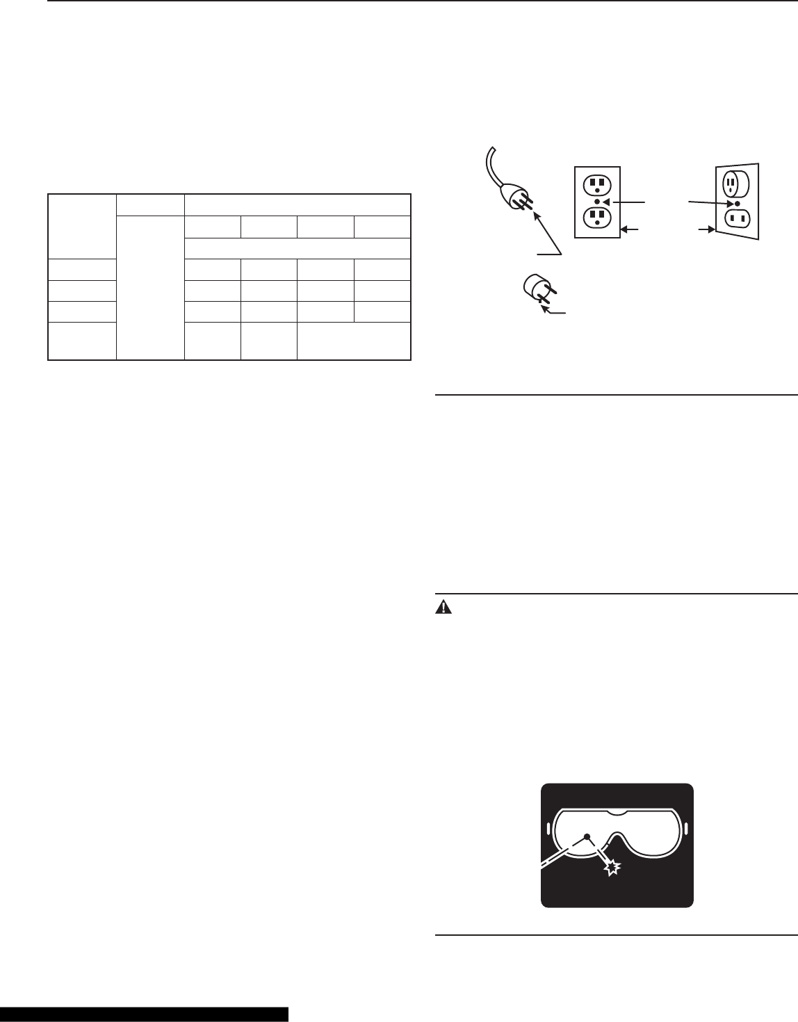
Grounded, cord-connected tools intended for use on a
supply circuit having a nominal rating less than 150 Volts:
• This tool is intended for use on a circuit with a grounded
outlet (B, Fig. 1). The tool has a grounding plug (A, Fig. 1).
• A temporary adapter (D, Fig. 1) may be used to connect
this plug to a 2-pole receptacle (C, Fig. 1), if a properly
grounded outlet is not available. The green-colored tab
extending from the adapter must be connected to a per-
manent ground, such as a properly grounded outlet box.
The temporary adapter should be used only until a quali-
ed electrician can install a properly grounded outlet.
Grounding
Pin
Metal
Screw
Cover Of
Grounded
Outlet Box
Adaptor
Grounding
Means
Adaptor Is Not Permitted In Canada
(B)
(A)
(C)
(D)
Fig. 1
Permanently Connected Tools
This tool can be permanently connected to a grounded,
metal, wiring system or to a system that has an equipment-
grounding conductor.
Ground-fault circuit interrupter (GFCI) protection should be
provided on the circuit or outlet to be used for the tile saw.
Receptacles are available having built-in GFCI protection
and may be used for this measure of safety.
Personal Safety
WARNING:
The operation of any power tool can result in foreign
objects being thrown into your eyes, which can result in
severe eye damage. Before beginning power-tool oper-
ation, always wear safety goggles or safety glasses with
side shields, and a full-face shield when needed. We
recommend Wide Vision Safety Mask for use over eye-
glasses or standard safety glasses with shields. Always
use eye protection, which is marked to comply with
ANSI Z87.1
FORESIGHT IS BETTER
THAN NO SIGHT
WEAR YOUR
SAFETY GLASSES
GENERAL SAFETY INSTRUCTIONS

5
• STAY ALERT, WATCH WHAT YOU ARE DOING, and
USE COMMON SENSE when operating a power tool.
• DO NOT use the tool while tired or under the inuence of
drugs, alcohol, or medication.
• WEAR PROPER APPAREL. Do not wear loose clothing,
gloves, neckties, rings, bracelets, or other jewelry. Pull
back and secure long hair. Non-slip footwear is recom-
mended.
• KEEP YOUR HAIR, CLOTHING, AND GLOVES AWAY
FROM MOVING PARTS.
• REMOVE ADJUSTING KEYS OR WRENCHES. Form a
habit of checking to see that keys and adjusting wrenches
are removed from the tool before turning it on.
• ALWAYS USE SAFETY GLASSES. Everyday glasses
may have impact-resistant lenses, but they are NOT safe-
ty glasses.
• USE A DUST OR FACE MASK, if the operation is dusty.
• WEAR HEARING PROTECTION to help prevent hearing
loss.
• NEVER TOUCH THE PINS OF THE ELECTRICAL PLUG
while inserting it into or removing it from an electrical
socket.
• NEVER STAND ON TOOL. Serious injury could occur if
the tool is tipped, or if the cutting tool is unintentionally
contacted.
Tool Safety
• KEEP ALL GUARDS IN PLACE and in working order.
• AVOID ACCIDENTAL STARTING. Be sure the switch is
in the “Off” position before plugging the tool into an elec-
trical outlet.
• DO NOT CARRY TOOLS WITH YOUR FINGER ON THE
SWITCH.
• DO NOT OVER REACH. Keep proper footing and bal-
ance at all times.
• DO NOT FORCE THE TOOL. Use the correct tool and
blade for your application. The correct tool and blade will
do the job better and more safely when used at the rate for
which they are designed.
• DO NOT USE TOOL IF THE SWITCH DOES NOT TURN
IT “ON” OR “OFF.” Any tool that cannot be controlled
with the switch is dangerous and must be repaired.
• DISCONNECT THE TOOL before servicing, when chang-
ing accessories (such as cutting blades), or storing the
tool.
• STORE IDLE TOOLS OUT OF THE REACH OF CHIL-
DREN and other untrained people.
• NEVER LEAVE THE TOOL RUNNING UNATTENDED;
turn the power off. Don’t leave the tool until it comes to a
complete stop.
• ALWAYS MAINTAIN TOOLS WITH CARE. Keep cutting
tools sharp and clean. Properly maintained tools with
sharp cutting edges are less likely to bind and are easier to
control. Follow all instructions for lubricating and changing
accessories.
• CHECK FOR DAMAGED PARTS. Before further use of
the tool, a guard or other part that is damaged should be
carefully checked to determine that it will operate properly
and perform its intended function. Check for alignment of
moving parts, binding of moving parts, mounting, and any
other conditions that may affect its operation. A guard or
other part that is damaged should be properly repaired or
replaced.
• USE RECOMMENDED ACCESSORIES. Consult the
product manual for recommended accessories. The use
of improper accessories may increase the risk of personal
injury.
Service Safety
• If any part of this wet-tile/stone saw is missing or should
break, bend, or fail in any way; or should any electrical
component fail to perform properly: ALWAYS shut off the
power switch and remove the plug from the power source,
and have the missing, damaged, or failed part replaced
BEFORE resuming operation.
• When servicing a tool, ALWAYS use only identical replace-
ment parts. Follow instructions in the Maintenance Sec-
tion on page 35 of this manual. Use of unauthorized parts
or failure to follow Maintenance Instructions may create a
risk of electric shock or injury.
GENERAL SAFETY INSTRUCTIONS
6
SPECIFIC SAFETY INSTRUCTIONS
FOR RIDGID WET TILE/STONE SAW
Safety Instructions for Wet Tile/Stone Saw
WARNING:
Be sure to read and understand all instructions in this
manual before using this Professional Wet Tile/Stone
Saw with Laser Guide, LED Work light and Stand. Failure
to follow all instructions may result in electric shock, fire
and/or serious personal injury
WARNING:
To reduce the risk of mistakes that could cause serious,
permanent injury, do not plug the tile saw into an electri-
cal receptacle until the following steps have been satis-
factorily completed:
• COMPLETELY ASSEMBLE THE SAW (See “Assembly”
section, page 13)
• LEARN THE USE AND FUNCTION OF THE ON-OFF
SWITCH, blade guard, laser-adjustment knob, overload
protector, spindle lock, depth-stop-adjustment knob,
depth-adjustment knob, bevel-cut-adjustment knob, uni-
versal guide, etc. (See “Getting to Know Your Tile Saw” on
page 24.)
• REVIEW AND UNDERSTAND ALL SAFETY INSTRUC-
TIONS AND OPERATING PROCEDURES in this manual.
• REVIEW THE MAINTENANCE METHODS for this saw
(See “Maintaining Your Saw” section, page 35).
• NEVER put your ngers or hands in the path of the saw
blade or other cutting tool.
• NEVER REACH BEHIND the cutting tool with either hand
for any reason. Do not reach behind the blade to hold
down the work piece, support the work piece, remove
scraps, or for any other reason.
• NEVER use a hand position where a sudden slip could
cause the ngers or the hand to move into a saw blade.
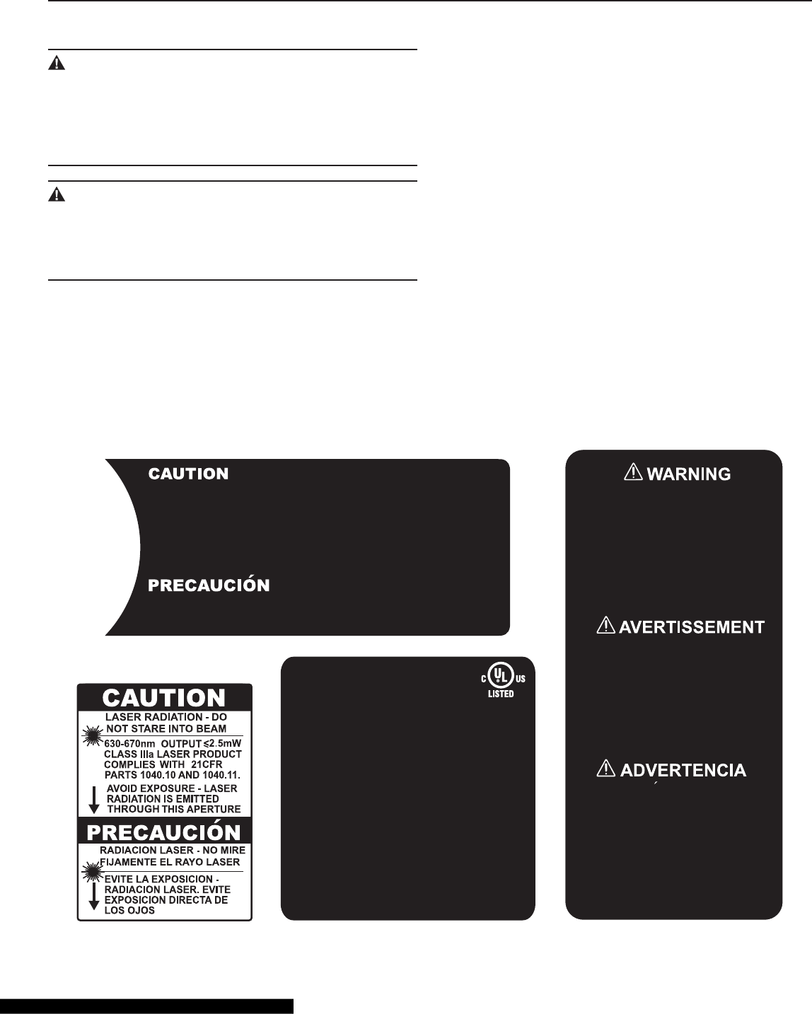
• FIND AND READ ALL THE WARNING LABELS found
on the tool (shown below).
1. To reduce the risk of electric shock, connect
only to a properly grounded, grounding type
receptacle.
2. To reduce the risk of electric shock, install
only on a circuit protected by a Ground-Fault
Circuit-Interrupter (GFCI).
3. Risk of electric shock - This pump has not
been investigated for use in swimming pool or
marine areas.
PP-399
Submersible Pump
120V 0.23A 60Hz
E204083
63VF
WARNING
CAUTION
IMPEDANCE PROTECTED
Acceptable For Indoor And Outdoor Use
This pump has been evaluated for use with
water only.
FOR YOUR OWN SAFETY, READ INSTRUCTION
MANUAL BEFORE OPERATING SAW
A) WEAR EYE PROTECTION
B) USE SPLASH HOOD FOR EVERY
OPERATION FOR WHICH IT CAN BE USED
C) DISCONNECT SAW BEFORE SERVICING,
WHEN CHANGING CUTTING BLADES, AND
WHEN CLEANING
D) USE TOOL ONLY WITH SMOOTH-EDGE
CUTTING BLADE FREE OF OPENINGS AND
GROOVES
E) REPLACE DAMAGED CUTTING BLADE
BEFORE OPERATING
F) DO NOT EXPOSE TO RAIN OR USE IN
DAMP LOCATIONS
LEE ESTA INSTUCCION MANUAL ANTES DE USA LA
SIERRA PARA TU BIEN
A) PONE EL PROTECTOR PARA LOS OJOS
B) USA UNA CAPUCHA PARA PROTEGERSE DE
LAS MANCHAS CUANDO USA LA SIERRA
C) DISCONECTA LA SIERRA CUANDO NO ESTA
USADA, O VA A CAMBIAR LA RUEDA DE CORTAR, O
VA A LIMPIARLA
D) CUANDO SE USA, SOLO USA LA PARTE LISA
DE LA RUEDA DE COETAR, Y DEJA LIBRE LA OTEA
PARTE Y LA PANURA
E) ANTES DE USAR LA SIERRA, TIENE QUE
CAMBIAR LA ROTA RUEDA DE CORTAR
F) NO LA DEJES EXPUESTA A LA LLUVIA NI LA
USES EN CONDCIONES MOJADAS
POUR ASSURER VOTRE SECURITE, LISEZ LE
MODE D'EMPLOI AVANT D'UTILISER LE COUPEUR
A) PORTEZ LES LUNETTES DE PROTECTION
B) PORTEZ LA CASQUE DE PROTECTION
PENDANT CHAQUE OPERATION
C) DECONNECTEZ LE MEULE AVANT
L'UTILISATION QUAND ON CHANGE LE MEULE DE
COUPAGE OU LE NETTOIE
D) UTILISEZ SEULEMENT L'OUTIL WITH LE
MEULE A BORD LISSE SANS RAINURE
E) REMPLACEZ LE MEULE AVEC DEGRATS
AVANT L'OPERATION
F) N'EXPOSEZ PAS DANS LA PLUIE OU UTILISE
DANS L'ENVIRONNMENT HUMIDE
MISE EN GARDE
ìST OP/GOî knob must be in the ìST OPî position before operating, moving or transporting
the saw.
For your safety, use the table lock to secure the working table before moving or transporting
the saw.
Líinterrupteur ´ marche/arrÍt ª doit Ítre en position ´ arrÍt ª avant díutiliser , de dÈplacer ou de
transporter la scie.
Pour votre sÈcuritÈ, enclenchez le verrouillage du plateau de travail avant de dÈplacer ou
transporter la scie.
La perilla de STOP/GO debe estar en la posiciÛn de ST OP (PARADA) antes de funcionar , de
mover o de transportar la sierra.
Para su seguridad, utilice la cerradura de la mesa para asegurar la mesa de trabajo antes de
mover o de transportar la sierra.
7
SPECIFIC SAFETY INSTRUCTIONS
FOR RIDGID WET TILE/STONE SAW
The labels on your tool may include the following symbols:
V . . . . . . . . . . . Volts
A . . . . . . . . . . . Amperes
Hz . . . . . . . . . . Hertz
W ........... Watts
~ . . . . . . . . . . Alternating Current
min . . . . . . . . . . Minutes
no . . . . . . . . . . No-load speed
RPM . . . . . . . . Revolutions or reciprocation per minute
. . . . . . . . . . Indicates danger, warning or caution.
It means ATTENTION! Your safety is
involved.
WARNING:
Use of this tool can generate dust-containing chemicals
known to the state of California to cause cancer, birth
defects, or other reproductive harm. Some examples of
these chemicals are:
• Lead from lead-based paints.
• Crystalline silica from bricks, cement, and other
masonry products.
• Arsenic and chromium from chemically treated lumber.
Your risk from these exposures varies, depending upon
how often do this type of work. To reduce your exposure
to these chemicals:
Work in a well-ventilated area.
Work with approved safety equipment, such as those
dust masks that are specially designed to filter out mi-
croscopic particles.
Avoid prolonged contact with dust from power sanding,
sawing, grinding, drilling, and other construction activi-
ties. Wear protective clothing and wash exposed areas
with soap and water.
Allowing dust to get into your mouth or eyes or to lie on
the skin may promote absorption of harmful chemicals.
Use of accessories that are not recommended for use
with this tool may create hazardous conditions.
• DIRECTION OF FEED: Always feed work into the blade
against the rotational direction of the blade.
• LET THE BLADE COME TO A COMPLETE STOP before
removing any jammed or off-cut material from around the
blade area.
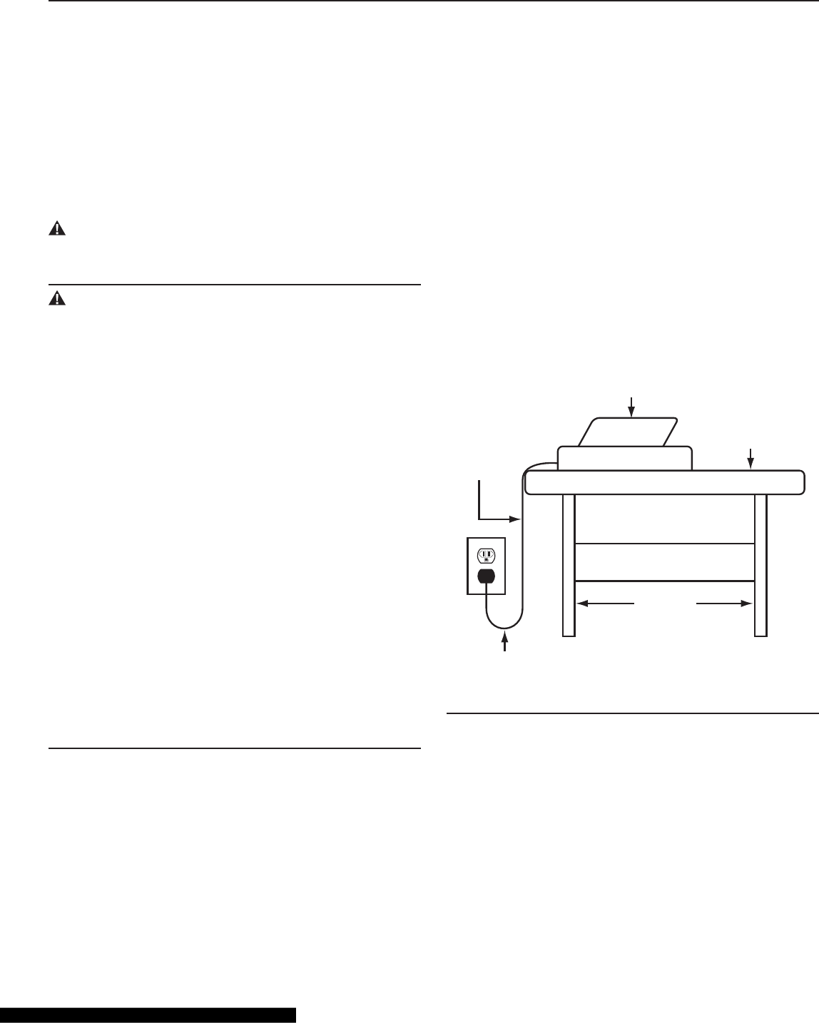
• POSITION OF TILE SAW: To avoid the possibility of the
appliance plug or receptacle getting wet, position the tile
saw to one side of a wall-mounted receptacle. The user
should arrange a “drip loop” in the cord connecting the
saw to a receptacle. (Fig. 2)
The “drip loop” is a section of the cord that hangs below the
level of the receptacle or below the connector, if an exten-
sion cord is used, to keep the water that travels along the
cord from coming into contact with the receptacle. (Fig. 2)
If the plug or receptacle does get wet, DON’T unplug the
cord. Disconnect the fuse or circuit breaker that supplies
power to the tool. Then unplug the tool and examine the
receptacle for water. Do not use the receptacle until it is
completely dry.
Power
Supply
Cord
Tile Saw
Drip Loop
Water Tray
Tile Saw
Support
Fig. 2
8
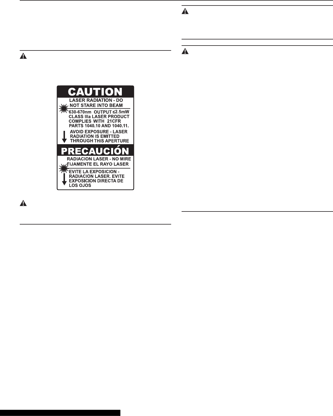
Safety Instructions for Laser
This saw has a built-in laser light. The laser is class IIIa and
emits output power of a maximum 2.5mW and 630~670nm
wavelengths. The laser doesn’t normally present an optical
hazard.
CAUTION
The following label is on your saw. It indicates where the
laser light is emitted by the saw.
CAUTION:
Avoid exposure. Laser radiation is emitted through this
aperture.
CAUTION:
The use of controls or adjustments or the performance
of procedures other than those directed in this manual
may result in hazardous radiation exposure.
WARNING:
Laser radiation. Avoid direct eye exposure. Do not stare
into the beam. Turn the laser on only when the tool is
operated.
Be sure to read and understand all instructions. Always
follow the following safety rules when using this saw:
NEVER aim the beam at any person or at any object
other than the work piece.
DO NOT look directly into the laser-beam output aper-
ture during operation. The laser beam can be harmful to
the eyes.
ALWAYS keep the laser out of the reach of children. The
laser on the saw is not a toy.
Using optical instruments with this product will increase
eye hazard.
DON’T ATTEMPT TO REPAIR OR DISASSEMBLE the
laser. If unqualified persons attempt to repair this prod-
uct, serious injury may result. Any repair required on this
laser product should be performed by authorized ser-
vice-center personnel.
SPECIFIC SAFETY INSTRUCTIONS
FOR RIDGID WET TILE/STONE SAW

9
Arbor
The shaft on which a cutting tool is mounted.
Bevel Cut
A cutting operation made across the width of the work piece
in which the cut is not perpendicular to the surface of the
work piece.
Flat Angle Cut
An angle-cutting operation made through the face of work
piece: The cut is perpendicular to the surface of the work
piece and is at an angle other than 90° to the edge of the
tile.
Freehand
Performing a cut without using a rip fence (guide), xture,
hold-down, or other proper device to prevent the work piece
from twisting during the cutting operation. Never cut free-
hand with this tool.
Off-Cut
The portion of the work piece that has been cut off.
Plunge Cut
A cutting operation in which the rotating blade is lowered
onto the work piece.
Revolutions Per Minute (RPM)
The number of turns completed by a spinning object in one
minute.
Straight Cut
A cutting operation parallel to the one straight edge of the
work piece.
Work Piece
The item on which the cutting operation is being performed.
The surfaces of a work piece are commonly referred to as
faces, ends, and edges.
Through-Sawing
Any cut that completely severs the work piece.
GLOSSARY OF TERMS
Power Supply And Motor Specifications
WARNING:
To reduce the risk of electrical hazards, fire hazards, or
damage to the tool, use a ground-fault circuit interrupt-
er. If the power cord is worn, cut, or damaged in any
way, replaced it immediately to reduce the risk of shock
or fire
The motor is wired for operation on 120v AC, 60 Hz service.
Rate H.P. 2-1/2
Voltage 120V
Amperes 15
Hertz (Cycles) 60
Phase Single
RPM 4200
Table 2
General Electrical Connections
WARNING:
To reduce the risk of electrocution:
1. Use only identical replacement parts when servic-
ing. Servicing should be performed only by a quali-
fied, service technician.
2. Do not use in rain or where the floor is wet. This tool
is intended for indoor, residential use only.
WARNING:
Do not permit fingers to touch the terminals of plug when
installing or removing the plug to or from the outlet.
MOTOR SPECIFICATIONS AND ELECTRICAL REQUIREMENTS
10
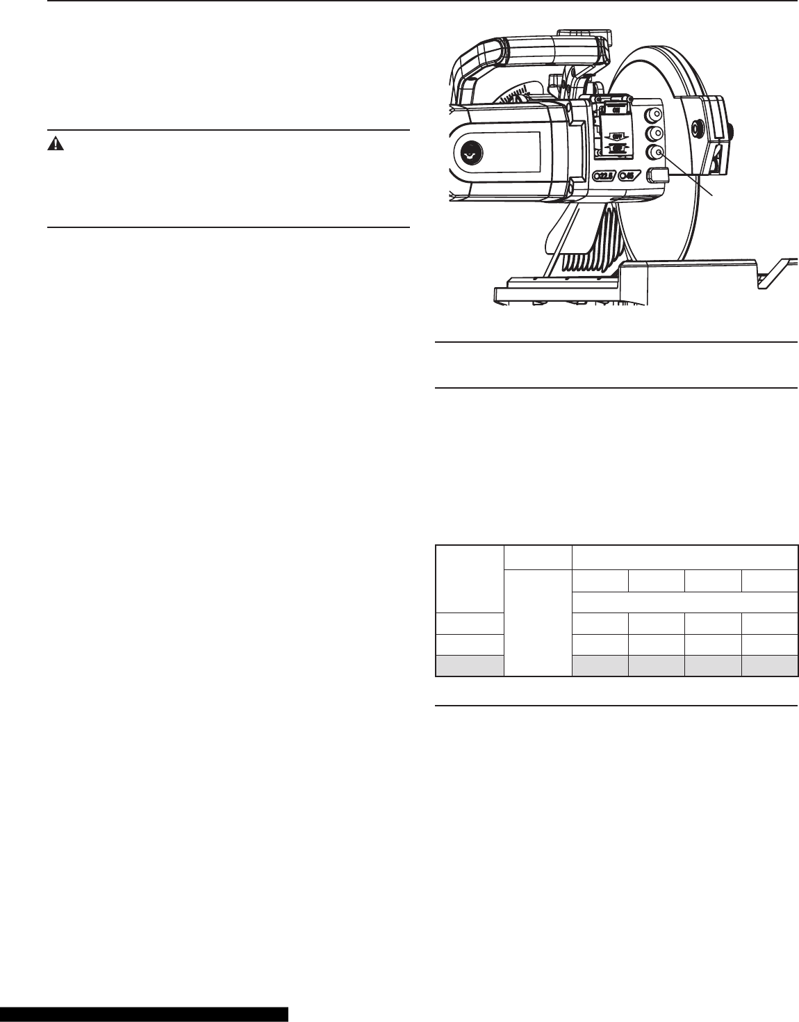
MOTOR OVERLOAD PROTECTOR
Your saw is equipped with a manual-reset, motor-overload
protector. The overload protector is designed to stop the
current to the saw when the motor current exceeds a safe
level, when the motor is overloaded, or when a low-voltage
condition exists.
WARNING:
If the motor-overload protector stops the saw motor,
immediately turn the saw switch to “OFF” and then allow
the motor to cool. This will reduce the risk of the saw
starting unexpectedly and causing harm or injury.
When the motor-overload protector stops the motor:
1. After cooling to a safe operating temperature, the over-
load protector can be reset by pressing the overload-
protector switch on the side of the motor. (See Fig. 3)
2. As soon as the overload-protector switch is reset, the
saw may be started and operated normally.
3. Frequent “tripping” of the overload protector may occur
under the following conditions:
— Motor is overloaded: Overloading can occur if you
feed the material to be cut too rapidly, or if saw blade
is misaligned.
— Low voltage: The saw motor is designed to operate
on the voltage specied on the motor nameplate.
Normal loads will be safely handled on voltages not
more than 10% above or below the nameplate volt-
age. Heavy loads, however, require that the voltage
at the motor terminals equals the voltage specied
on nameplate.
4. Most motor troubles may be traced to loose or incorrect
connections, overloading, reduced input voltage (such
as small-size wire in the supply circuit), or to an overly
long supply-circuit wire. Always check the connections,
the load, and the supply circuit whenever the motor fails
to perform satisfactorily.
MOTOR SPECIFICATIONS AND ELECTRICAL REQUIREMENTS
Overload
Protector
Switch
Fig. 3
Wire Sizes
NOTE:
Use proper extension cord. Make sure that the extension
cord is in good condition and is heavy enough to carry the
current your tool will draw. This tool draws 15 amps. Table 1
shows the correct size to use. An undersized cord will cause
a drop in line voltage resulting in loss of power and over-
heating. If in doubt, use the next heavier gauge: the smaller
the gauge number, the heavier the cord.
Ampere
Rating
Volts Total Length of Cord in Feet
120V~
25 ft. 50 ft. 100 ft. 150 ft.
A. W. G.
6~10 18 16 14 12
10~12 16 16 14 12
12~16 14 12 — —
Table 3
11
UNPACKING AND CHECKING CONTENTS
Unpacking
The WTS2000L tile saw comes in one carton.
Separate all the parts from the packing materials. Refer to
the “List of Loose Parts” below and “List of Main Parts” on
page 12 to make certain that all the items are accounted for
before discarding any packing material. Call RIDGID® Ser-
vice Center if any parts are damaged or missing.
WARNING:
If any parts are missing, do not attempt to assemble the
tile saw, plug in the power cord, or turn on the switch
until the missing parts are obtained and are installed
correctly.
NOTE: Before beginning assembly
• Check the “List of Loose Parts” and “List of Main Parts” to
make certain that all the items are accounted for. Check
that all the parts are included. If you are missing any part,
do not assemble the saw.
• Sometimes, small parts can get lost in packaging material.
Do not throw away any packaging until the saw is fully as-
sembled. Check the packaging for missing parts before
contacting RIDGID.
• A complete parts list is at the end of the manual. Use this
list to identify the part number of the missing part.
WARNING:
For your own safety, never connect a plug to a power
source outlet until all assembly steps are complete and
you have read and understand the safety and operating
instructions.
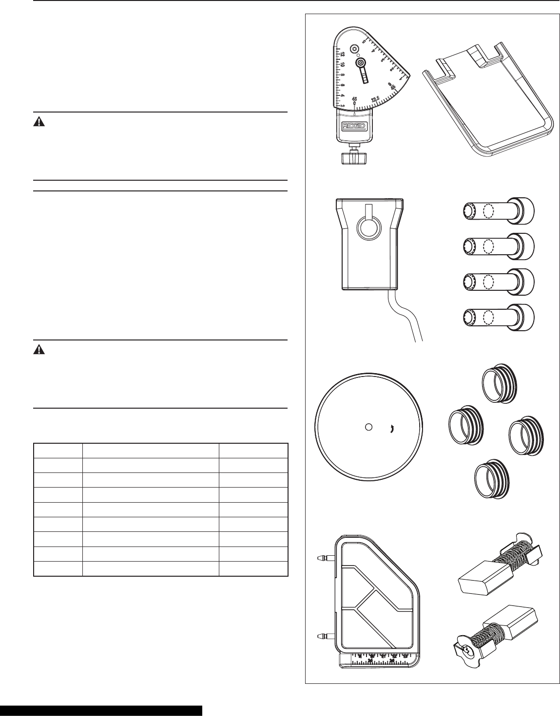
List of Loose Parts
Item Part Name QuaNtIty
A Universal Guide 1
B Water Pump 1
C Saw Blade 1
D Extension Table 1
E Extension Water Tray 1
F Bolt 4
G Bolt Cover 4
H Carbon Brush 2
A E
BF
CG
DH
12
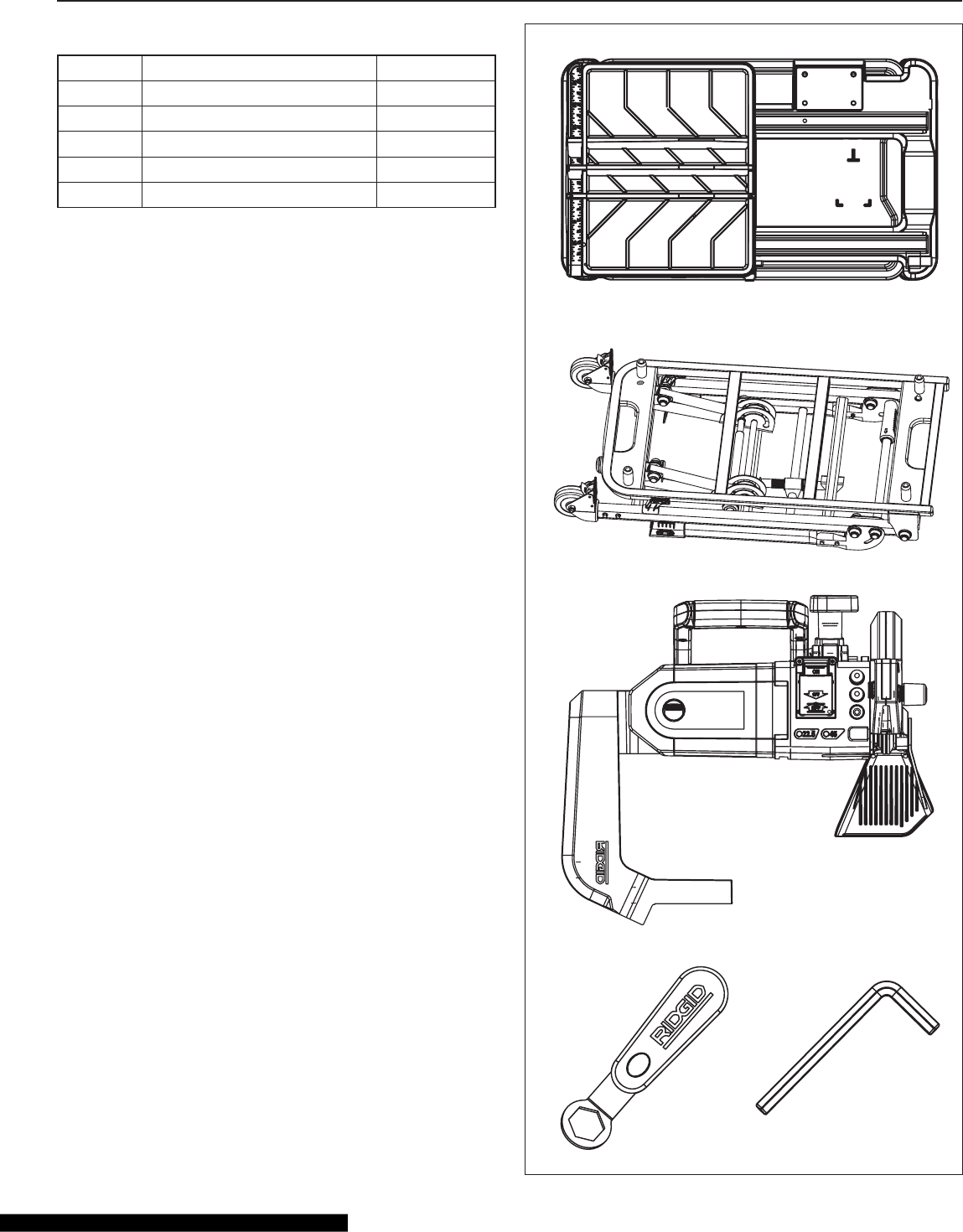
UNPACKING AND CHECKING CONTENTS
List of Main Parts
Item Part Name QuaNtIty
I Frame Assembly & Water Tray 1
J Stand 1
K Motor Assembly 1
L Nut Wrench 1
M Hex Wrench 1
*
+
,
L M
13
ASSEMBLY
In addition to the nut wrench and hex wrench supplied with
your saw, no tools are needed for assembly.
Stand Set-Up
CAUTION:
To avoid serious injury when lifting the saw, bend your
knees and lift with your legs, not with your back.
The saw can be placed on a at surface for cutting opera-
tions without using the stand. (Fig. 4)
When using the stand, observe the following instructions:
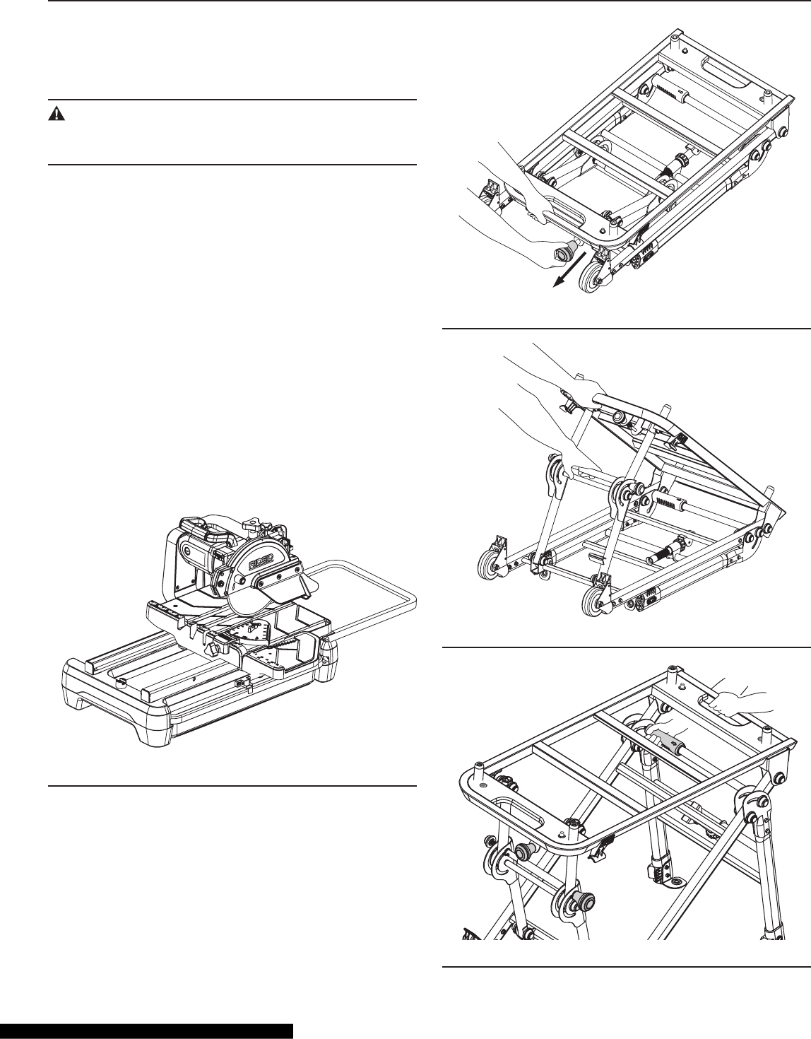
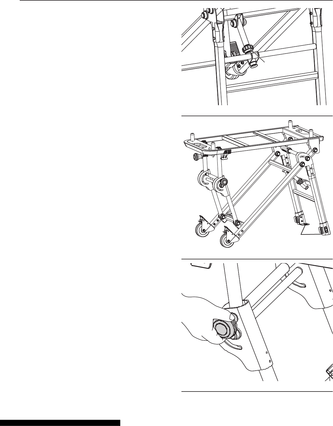
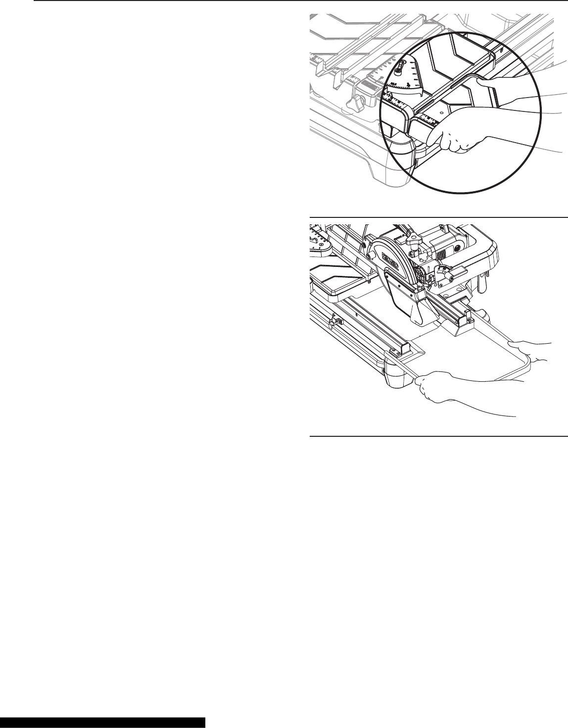
To Open the Stand:
1. Place the folded stand on a at surface, as shown in
Fig. 5.
2. Pull out the lock knob, then lift the handle (Fig. 5).
3. Continuing to lift the handle, pull the crossbar out until
you hear the legs lock in place (Fig. 6).
4. On the opposite end of the stand, locate the handle and
the orange lock sleeve on the crossbar, and note the
arrow on the lock sleeve. Lift the handle and move the
lock sleeve in the direction of the arrow on the sleeve.
Allow the legs to fall (Fig .7), and then release the sleeve.
Hold the lift handle, and pull the lower crossbar until you
hear the legs lock into place.
Fig. 4
Fig. 5
Fig. 6
Fig. 7
14
ASSEMBLY
Stand Set-Up, continued
5. Tighten the locking nut (Fig 8). Make sure all connec-
tions are rm and the stand is steady.
6. The stand anchors located on the two shorter legs (Fig.
9) may be used to attach the stand to the oor with
screws (not supplied).
Closing the Stand
From the side of the stand with two wheels, rst pull out the
orange knob at the end of the crossbar, as shown in Fig. 10,
then reverse the steps described in “To Open the Stand,”
page 13.
Locking Nut
Fig. 8
Stand Anchors
Fig. 9
Fig. 10
15
ASSEMBLY
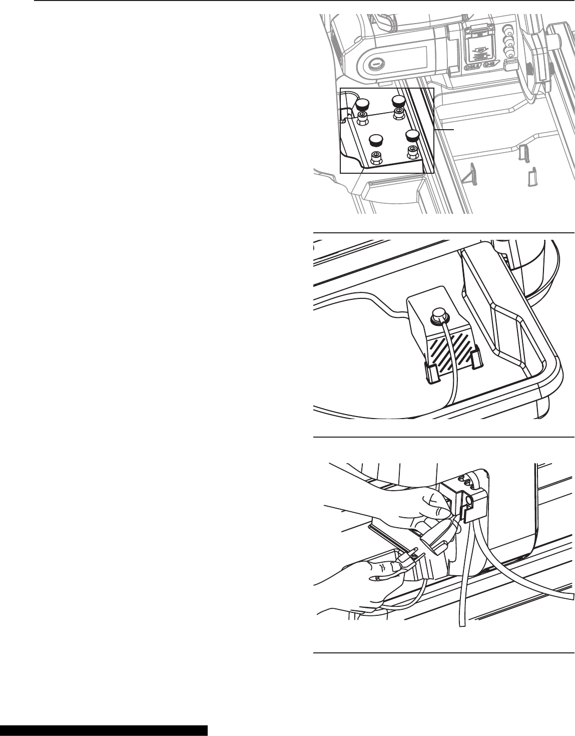
Installing the Motor Assembly
Position the motor assembly onto the frame assembly. Using
the hex wrench supplied, rst install and tighten the four
bolts, then place the four bolt covers on the bolts (Fig. 11).
Installing the Water Pump
1. Connect the end of the water hose to the water outlet
on the water pump.
2. Locate the water-pump-positioning tabs in the water
tray. With the water tray in place beneath the saw, posi-
tion the water pump as shown in Fig. 12. Press the wa-
ter pump in place to secure it to the water tray with the
attached suction cups.
3. Connect the water-pump power cord to the receptacle
on the saw, as shown in Fig. 13.
4 Bolts and
Bolt Covers
Fig. 11
Fig. 12
Fig. 13
16
ASSEMBLY
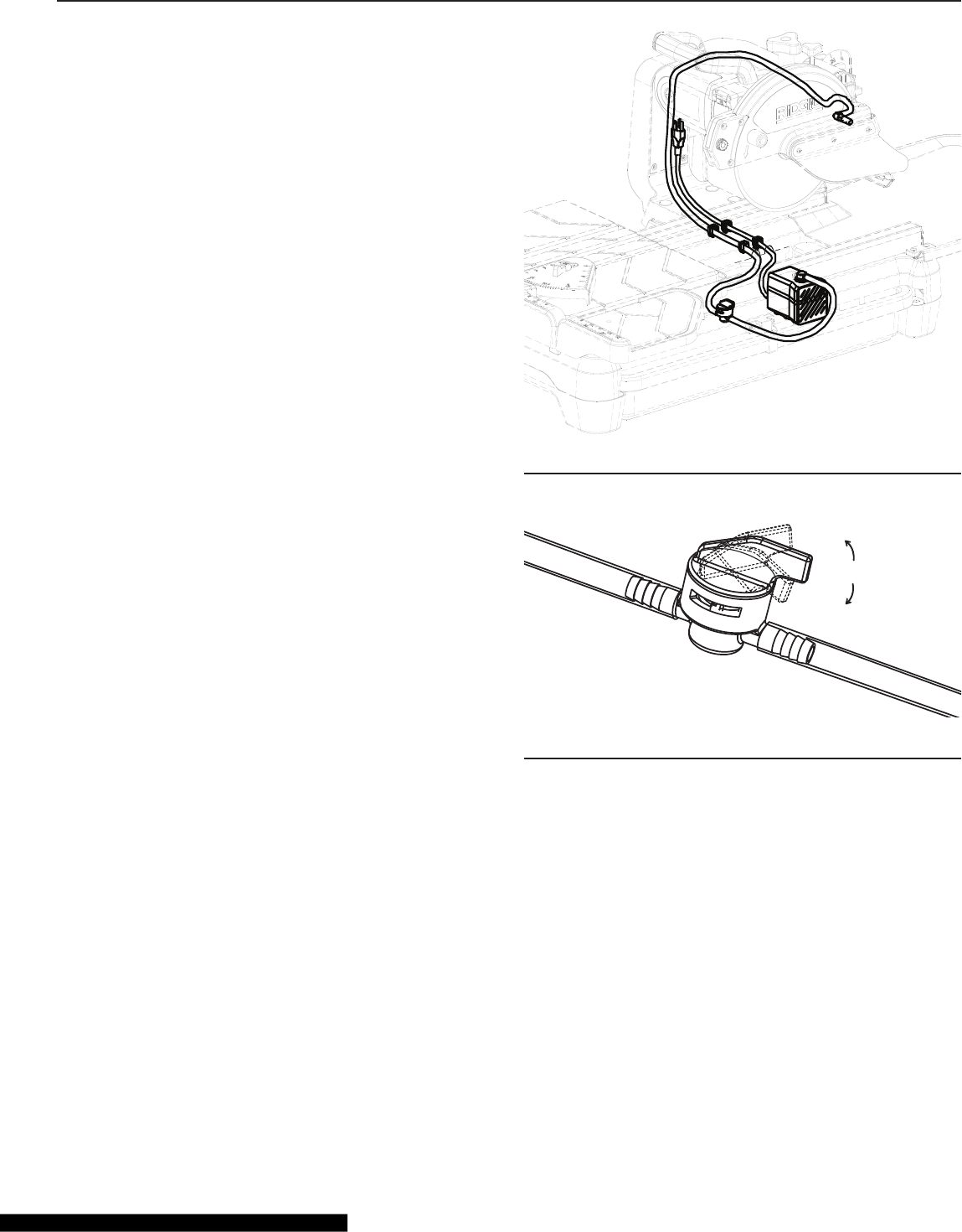
Installing the Water Pump, continued
4. Locate the 4 clips in the 2 grooves beneath the work
table, close to the motor-mounting arm (Fig. 14). Use 2
clips to lock the water hose into one groove and 2 clips
to lock the power cable into the other groove, as shown
in Fig. 14.
5. Please refer to Fig. 15 for the “OFF” and “ON” positions
of the water-hose valve.
Fig. 14
ON
OFF
OFF
Fig. 15
17
ASSEMBLY
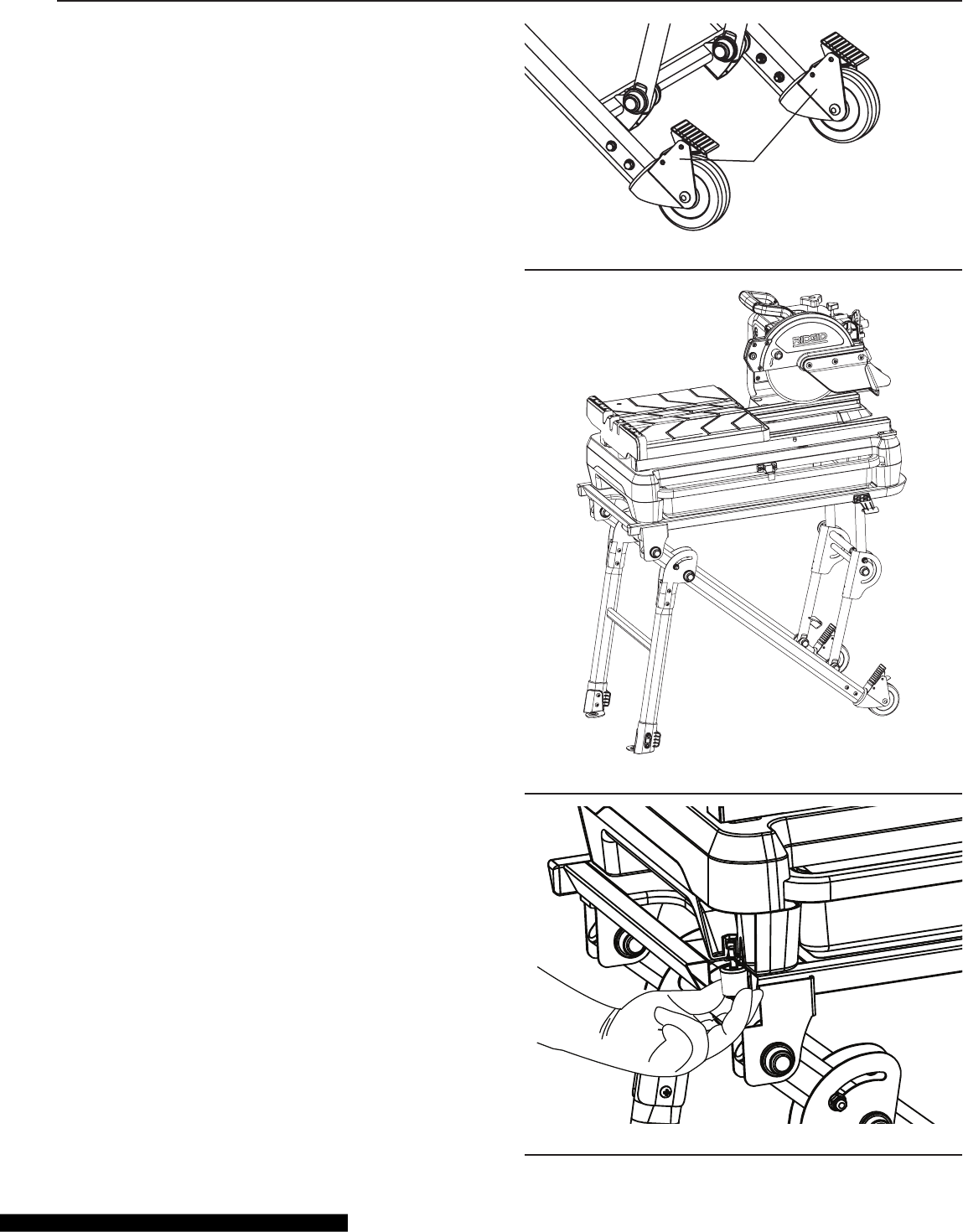
Mounting Your Saw
Before mounting the saw on the stand, make sure that both
wheels on the stand are locked (Fig. 16).
Place the saw on the stand. Make sure that the motor hous-
ing is positioned above the wheels and that the four mount-
ing holes of the saw-frame assembly are seated securely on
the four pins on the top of the stand (Fig. 17).
Locate the two fastening screws on the saw frame. Tighten
the two knobs attached to the stand on opposite corners
to securely fasten the saw to the stand (Fig. 18).
Locking Wheels
Fig. 16
Fig. 17
Fig. 18
18
ASSEMBLY
Installing the Extension Table
Insert the pins of the extension table into the holes of the
work table as shown in Fig. 19. Make sure that the extension
table is securely in place.
Installing the Extension Water Tray
Insert the extension water tray into the two latches at the
end of the rails until it locks into place (Fig. 20).
Fig. 19
Fig. 20
19
ASSEMBLY
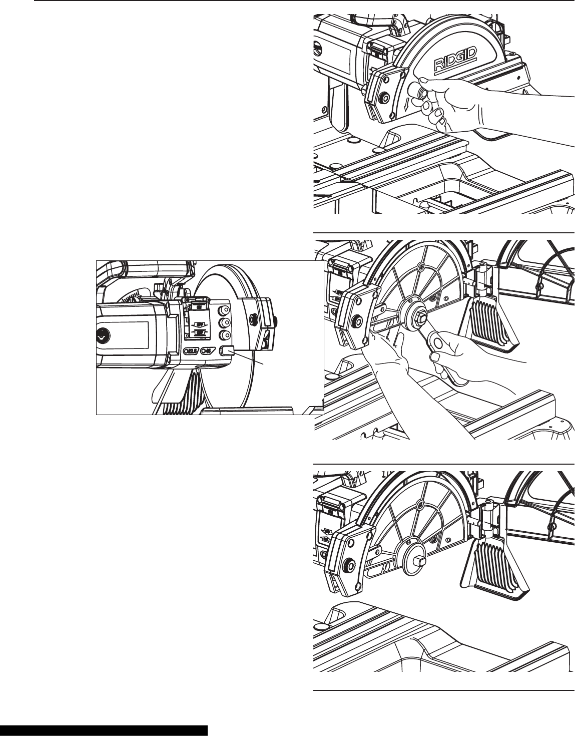
Installing the Saw Blade
1. Loosen the blade guard release knob (Fig. 21).
2. To open the blade guard, press the spindle lock with one
hand, and, with the other hand, use the nut wrench (sup-
plied) to turn the shaft nut counterclockwise (Fig. 22).
3. Remove the motor-shaft nut and the outer ange. Leave
the inner ange on the blade shaft (Fig. 23).
Fig. 21
Fig. 22
Fig. 23
Spindle
Lock
20
ASSEMBLY
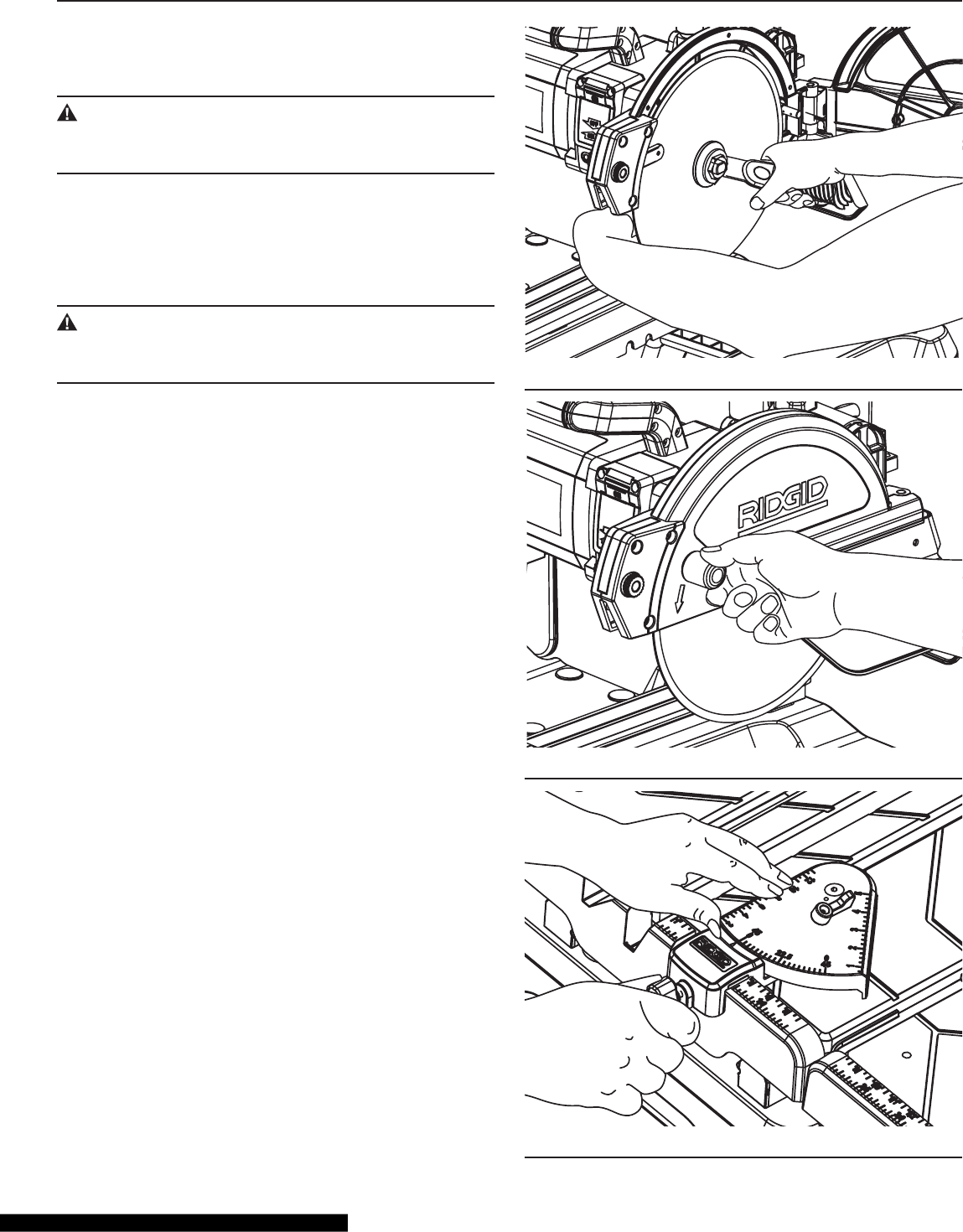
Installing the Saw Blade, continued
4. Fit the blade onto the motor shaft. Replace the outer
ange and the motor-shaft nut.
CAUTION:
Make sure that the arrow on the blade points in the same
direction as the arrow marked on the blade guard.
5. Press the spindle lock, while securely tightening the
motor-shaft nut on the motor shaft with the wrench sup-
plied (Fig. 24).
6. Close the blade guard, and tighten the blade guard
release knob (Fig. 25).
CAUTION:
To avoid damaging the blade guard when opening the
guard, do not open the blade guard beyond 90°.
Installing the Universal Guide
Slide the universal guide onto the worktable fence. Tighten
the universal-guide screw to secure it. (Fig. 26)
Fig. 24
Fig. 25
Fig. 26
21
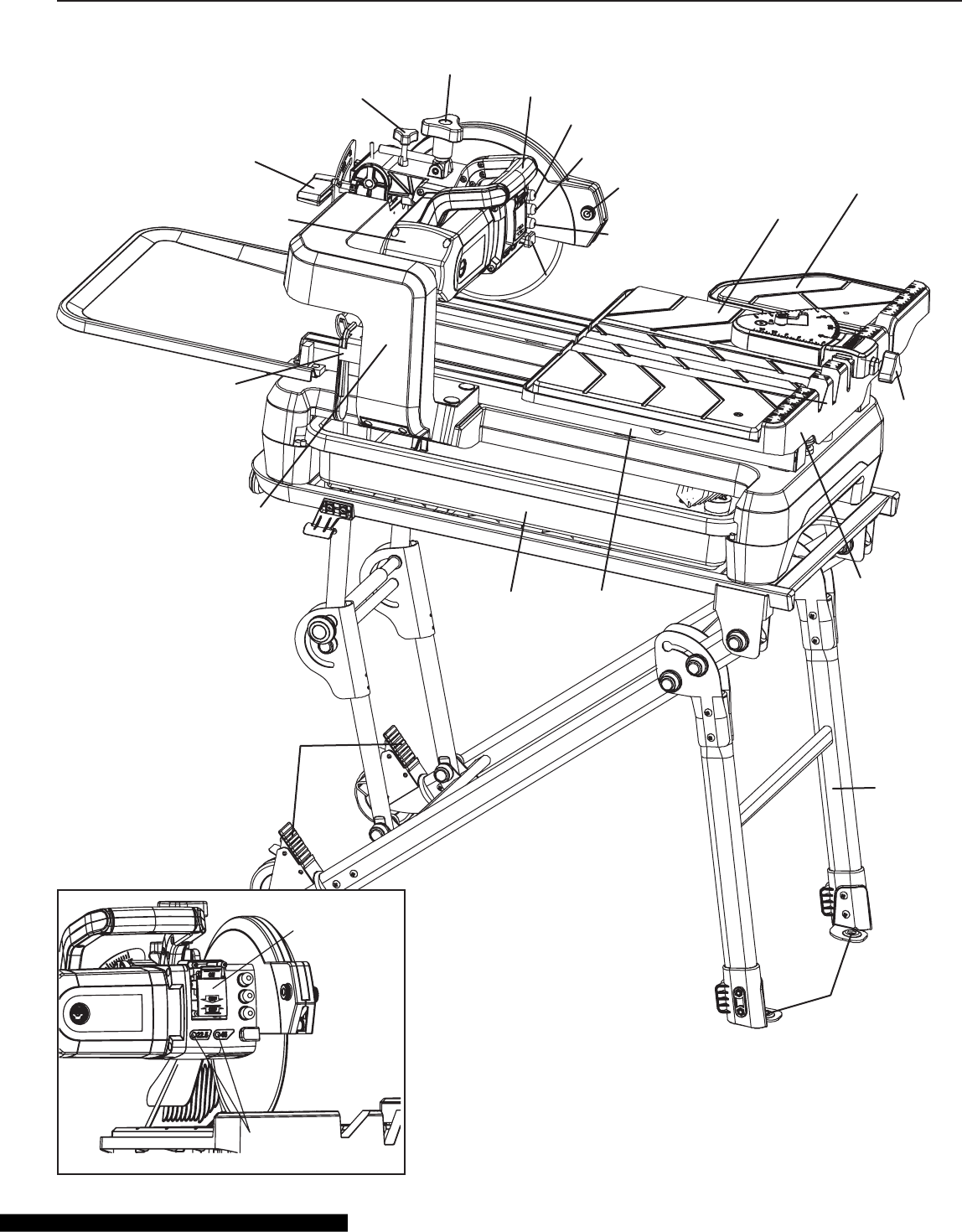
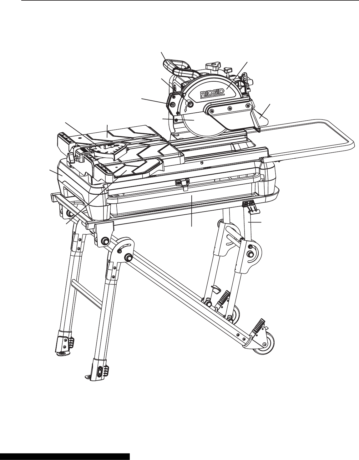
GETTING TO KNOW YOUR WET TILE/STONE SAW
LED Switch
Laser Switch
Worktable
Fence
Rail
Water Tray
Stand
Wrench
Storage
Clips
Extension
Water Tray
Support Arm
Motor Unit
Bevel Cut
Adjustment
Knob Extension
Table
Laser Alignment
Adjustment Knob
Overload
Protector
Spindle
Lock
Wheel Locks
Stand
Anchors
Work
Table
Depth
Adjustment
Knob
Depth Stop
Adjustment
Knob
On/Off
Switch
22.5°, 45° Bevel
Cut Indicator
Handle
Universal
Guide
Screw
22
GETTING TO KNOW YOUR WET TILE/STONE SAW
Blade Guard
Laser Angle
Adjustment
Knob
Blade
Extension
Table
Anti-Splash
Guard
Handle
Extension
Water Tray
Stand
Water Tray
Frame
Work Table
Universal
Guide
Blade Guard
Release Knob
23
GETTING TO KNOW YOUR WET TILE/STONE SAW
ON/OFF Switch (Fig. 27)
WARNING:
Before turning the switch “ON,” make sure that the
blade is correctly installed and operating properly.
a) Lift the switch to turn the saw on. After turning the
switch ON, always allow the blade to come up to full
speed before cutting. Do not rapidly cycle the motor
switch on and off, as this may cause the saw blade to
loosen. If this occurs, allow the saw blade to come to a
complete stop, and retighten the shaft nut, taking care
to not over-tighten the nut. Never leave the saw while
the power is “ON.”
On/Off
Switch
Fig. 27
b) To turn saw OFF, press the switch down. Never leave
the saw until the cutting blade has come to a complete
stop.
Blade Guard
The blade guard is a safety device. It can be opened or
closed by turning the knob on the blade guard. Make sure
that the blade guard is locked before cutting.
Laser Switch
To turn on the laser beam, press the laser switch; to turn off
the laser, press the switch again. Always turn off the laser
beam when you nish cutting.
LED Switch
To turn on the LED lights, press the LED switch; to turn off
the LED lights, press the switch again. The LED lights help
to illuminate your work.
Overload Protector Switch
Please read “Motor Overload Protector” in the “Motor Spec-
ication and Electrical Requirements” section.
Laser-Beam Adjustment Knob
Align the laser beam with the cutting line by adjusting one or
both adjustment knobs on the sides of the blade guide.
Please see the Laser Beam Calibration in the Adjustments
section of this manual.
Spindle Lock
Press the spindle lock to keep the shaft from rotating while
changing the saw blade.
Blade
To install and change the blade, see “Installing Saw Blade”
on page 19 of this manual.
Extension Table
Attaches to the work table to support large work pieces.
Universal Guide
Read “Universal Guide Adjustment” on page 27 of this manual.
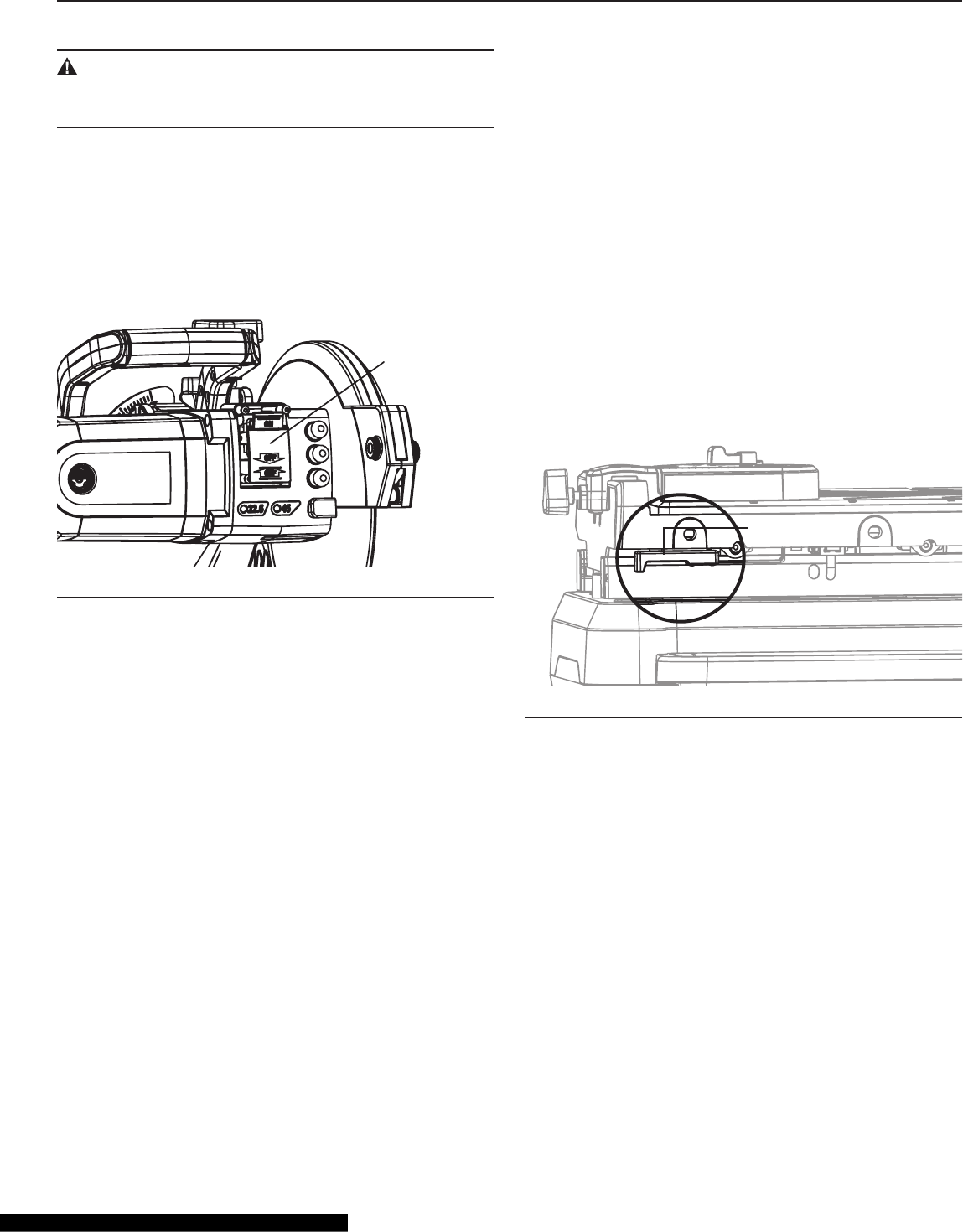
Table Lock
Lock the work table in one of two positions with the table-
lock. Press the table lock, and the work table can move
freely along the rails. Move the work table to one of the two
locking positions, and pull out the table lock to insert the
locking pin into one of the holes: the work table is locked in
position on the rails. (Fig. 28)
Table Lock
Fig. 28
Work Table
The work platform can be moved along the rails.
Rails
The work table is moved along the two rails when cutting a
work piece.
Frame
The base of the tile saw.
Water Tray
Holds the water needed to cool the blade. Read “Filling The
Water Tray” in the “Operation” section of this manual.
Stand
May be used to support the tile saw. The stand can be xed
in place with the two mounting holes and two screws (not
supplied). The two wheels aid in moving the stand; please
see “Moving the Saw” on page 34 of this manual.

24
22.5°/45° Bevel-Cut Indicator
Lights that indicate that the saw is positioned for a 22.5° or
45° bevel cut.
Anti-Splash Guard
Minimizes the over-spray and mist when cutting a work
piece.
Wrench Storage Clips
Conveniently holds the nut wrench and hex wrench when
they are not in use.
Extension Water Tray
Catches over-spray from large tile and redirects water into
the water tray.
Support Arm
Supports the motor unit on the frame.
Motor Unit
Powers the tile saw.
Bevel-Cut Adjustment Knob
To adjust the angle of the saw blade for a bevel cut, please
read “Bevel Cut Adjustment” on page 26.
Handle
For raising or lowering the saw unit.
Depth-Adjustment Knob
Please read “Depth Adjustment” on page 25.
Depth-Stop-Adjustment Knob
Please read “Depth Stop Adjustment” on page 25.
Work-Table Fence
Includes scale rules.
Wheel Locks
Used to stop the stand from rolling.
Stand Anchors
May be used to x the stand to the oor.
Laser Adjustment Knob
Align the laser beam with the cutting line by adjusting one or
both adjustment knobs on the sides of the blade guide.
Please see Laser Beam Calibration on page 28.
Blade-Guard Release Knob
Please see Installing the Saw Blade on page 19.
WARNING!
The use of any accessory or attachment or the perfor-
mance of any operation with this tool other than those
recommend in this instruction manual may present a
risk of personal injury.
Technical Specifications
Power Supply 120V~, 60Hz
Motor Capacity 15A
No-Load Speed 4200 RPM
Diamond Blade Size 10" x 5/64" x 5/8"
Maximum Tile Depth of Cut at 0° 3-3/4"
Tilting Range 0°, 22.5°, 45°
Maximum Rip Cut 24" Square
Maximum Diagonal Cut 18" Square Tile
GETTING TO KNOW YOUR WET TILE/STONE SAW
25
WARNING:
For your own safety, turn the switch to “OFF” and remove
the plug from the power-source outlet before making
any adjustment.
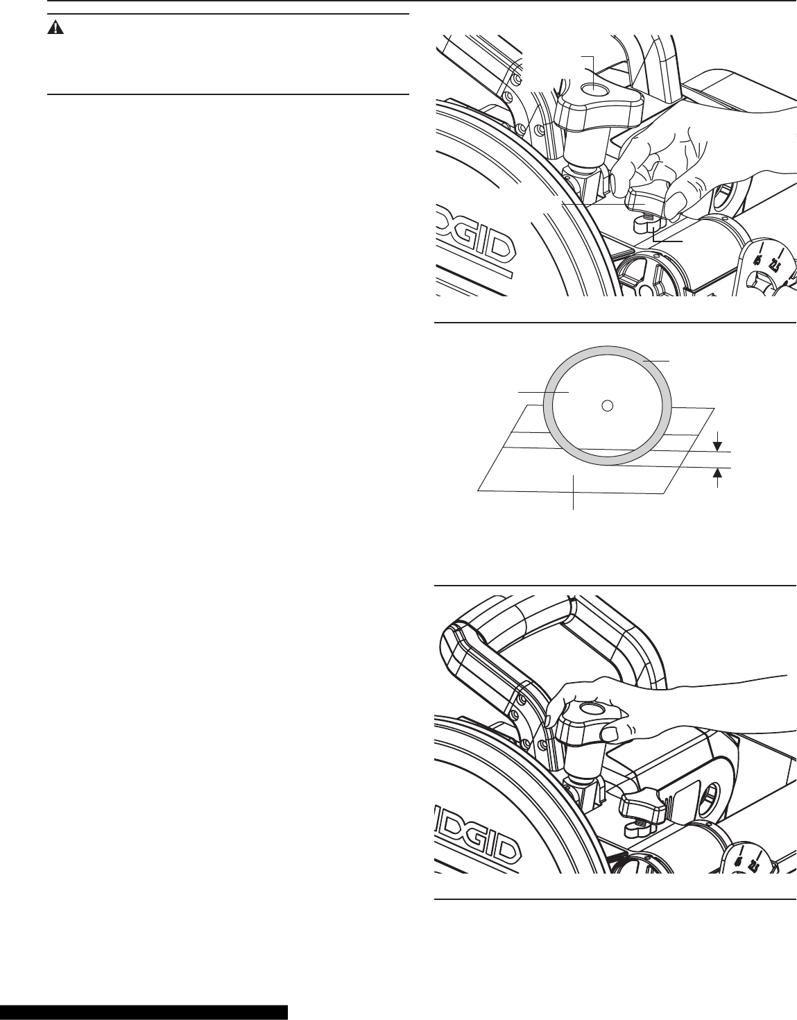
Depth Adjustment (Fig. 29)
Use the depth-adjustment knob to adjust the lowest posi-
tion of the blade:
1. Loosen the depth-stop-adjustment knob and the lock-
ing nut (located under the depth-adjustment knob).
2. Use the handle to lower the cutting head to its lowest
position.
3. Turn the depth-adjustment knob to raise or lower the
lowest position of the blade.
4. Tighten the locking nut.
5. Tighten the depth-stop-adjustment knob.
To cut all the way through the work piece, make sure that
the lowest position of the blade is 3/16" (5 mm) below the
surface of the work table (Fig. 30).
Depth-Stop Adjustment (Fig. 31)
The depth-stop-adjustment knob is used to lock the cutting
head in position.
1. Loosen the depth-stop adjustment knob.
2. Hold the handle to raise or lower the saw blade to the
desired position.
3. Turn the knob to lock the cutting head in place.
ADJUSTMENTS
Depth Stop
Adjustment
Knob
Depth Stop
Adjustment
Knob
Depth
Adjustment
Knob
Depth
Adjustment
Knob
Locking
Nut
Fig. 29
SURFACE OF WORKING TABLE
3/16" (5mm)
BLADE
BLADE RIM
Fig. 30
Fig. 31
26
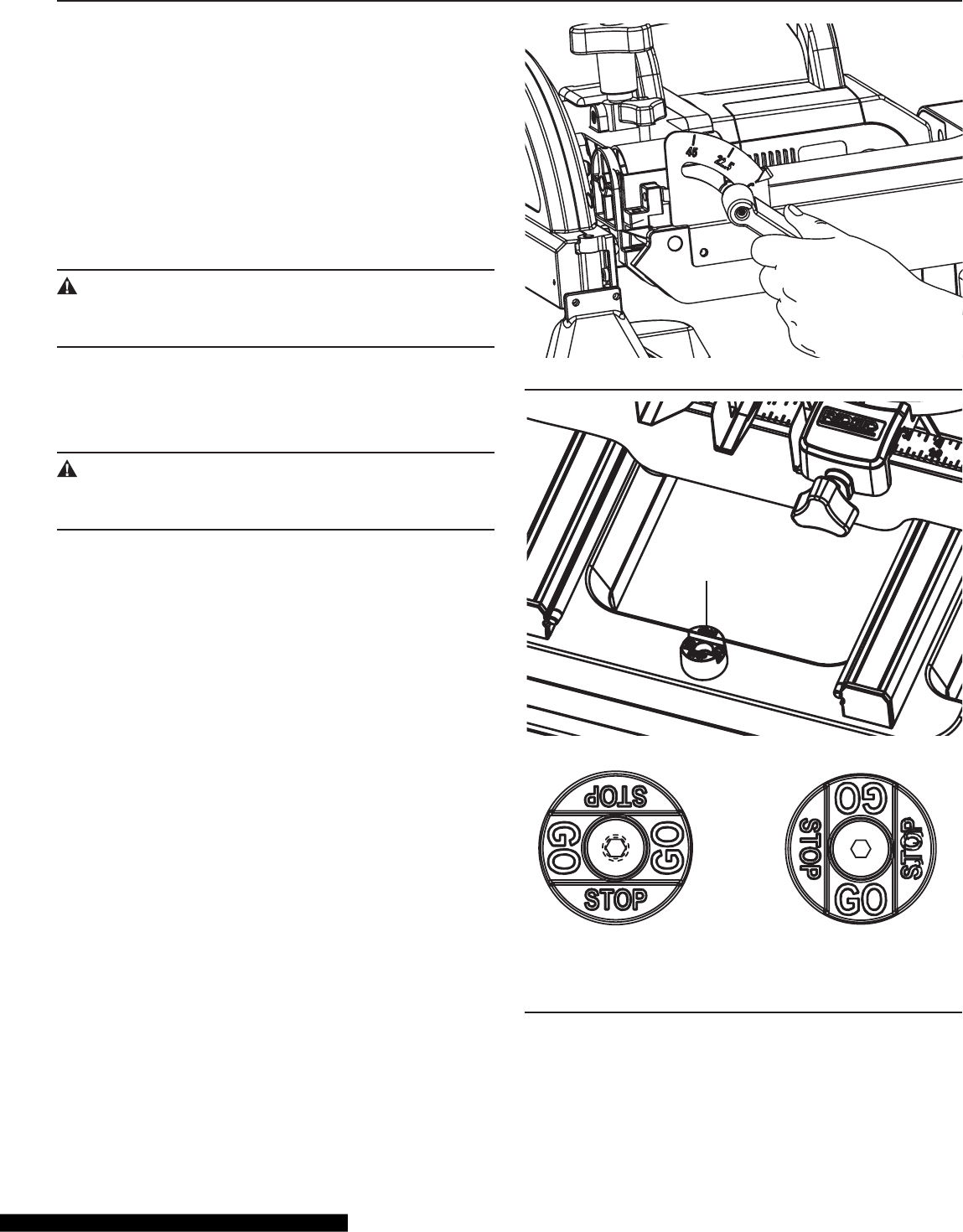
Bevel Cut Adjustment (Fig. 32)
The saw is adjustable to three bevel angles: 0°, 22.5°, and
45°. The three grooves in the work table accommodate the
three bevel-cut positions. When tilting the saw to 22.5° or
45°, the 22.5°/45° bevel indicator will be turned on.
1. Loosen the bevel-cut-adjustment knob in the rear of the
saw.
2. Tilt the saw to the desired angle (0°, 22.5° or 45°). Tight-
en the bevel-cut-adjustment knob.
Work Table Stop/Go Adjustment (Fig. 33)
CAUTION:
Make sure the “Stop/Go” knob is in the “STOP” position
before operating, moving, or transporting the saw.
Turn the knob to the “GO” position, and the work table can
be slid off the rails for transport or storage. Turn the knob to
the “STOP” position, and the work table cannot be moved
off of the rails.
WARNING:
To avoid injury, take care when removing the work table
from the rails.
ADJUSTMENTS
Fig. 32
STOP/GO KNOB
Stop Position Go Position
Fig. 33
27
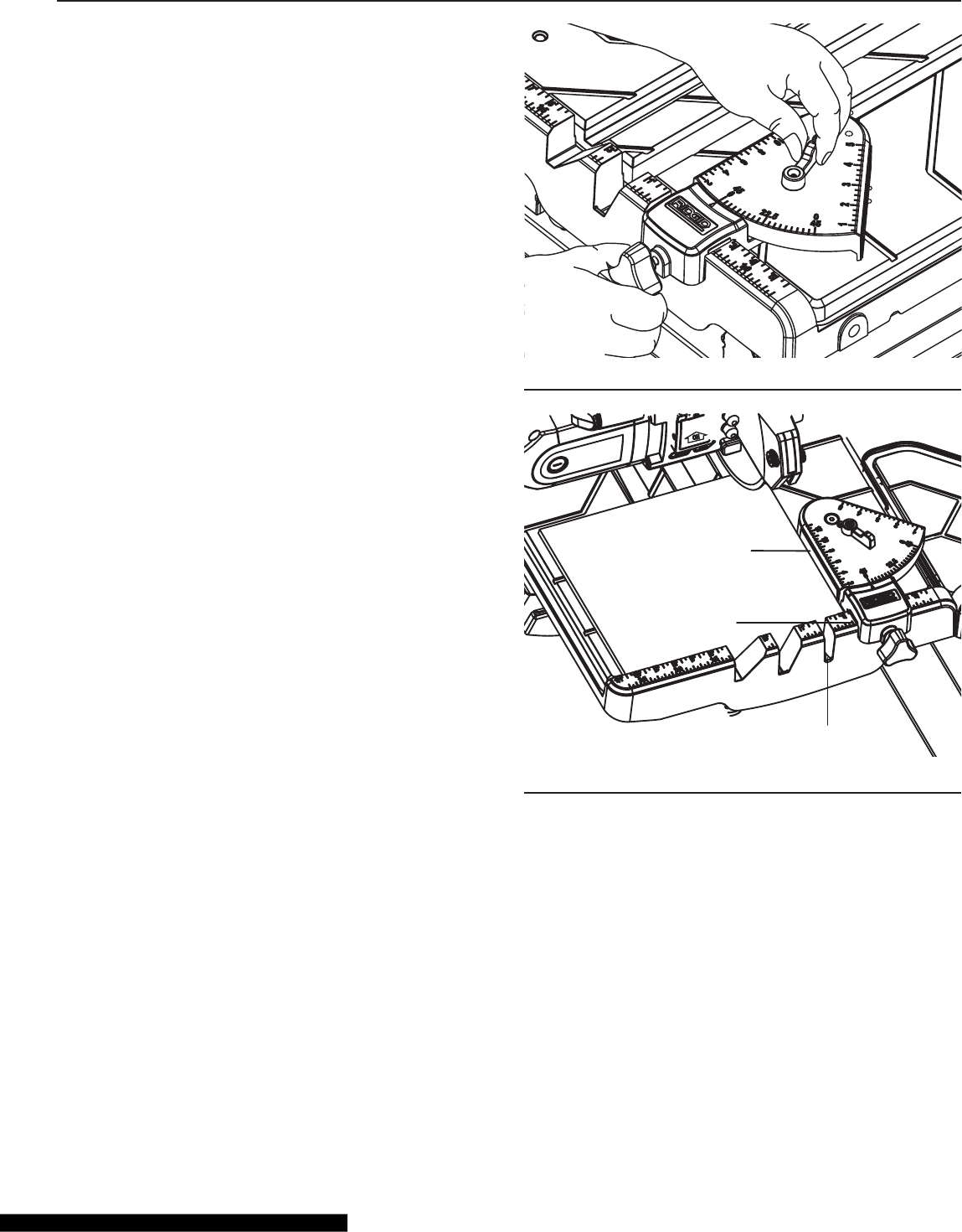
Universal Guide Adjustment
The universal guide can be used as a rip fence or an angle
guide. The universal guide has three positive stops: 0°, 22.5°
and 45°.
To adjust the universal guide:
1. Loosen the lever on the universal guide.
2. Adjust the universal guide so that the desired angle
(0° - 45°) aligns with the indicator arrow (Fig. 34). Tight-
en the lever to lock the universal guide at the desired
angle.
For straight cutting, the universal guide is used as rip fence
(Fig. 35).
1. Set the angle to 45°.
2. Loosen the universal-guide screw and position the guide
to the desired distance from the saw blade.
ADJUSTMENTS
Fig. 34
Side Of
Universal
Guide
Groove Edge
Zero Scale
Fig. 35
28
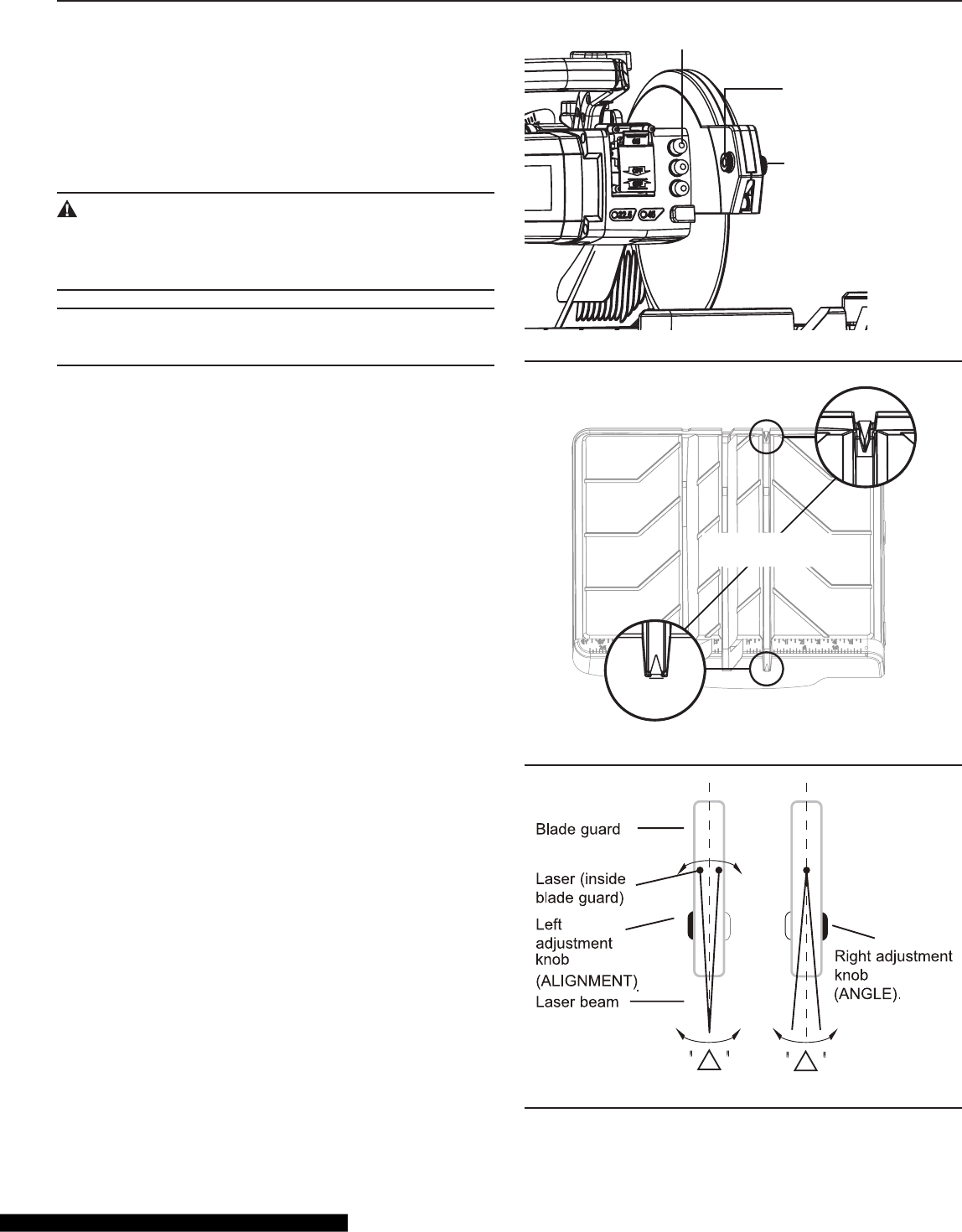
Laser Beam Calibration
Press the laser switch to turn on the laser (Fig. 36).
To adjust the alignment and angle of the laser beam, turn the
right knob (Laser ANGLE Adjustment) and the left knob
(Laser ALIGNMENT Adjustment) alternately until the laser
beam goes across the two ▲marks engraved in the slot of
the work table (Fig. 37, Fig. 38).
WARNING:
DO NOT stare directly at the laser beam. Never aim the
light at any person or at any object other than the work
piece.
NOTE: If you want to use laser as a cutting guide, make sure
that the laser beam is aligned with the cutting line.
ADJUSTMENTS
LASER SWITCHLASER SWITCH
LASER ALIGNMENT
ADJUSTMENT KNOB
LASER ALIGNMENT
ADJUSTMENT KNOB
LASER ANGLE
ADJUSTMENT KNOB
Fig. 36
ENLARGEMENT OF
ALIGNMENT TRIANGLES
ENLARGEMENT OF
ALIGNMENT TRIANGLES
Fig. 37
Fig. 38
29
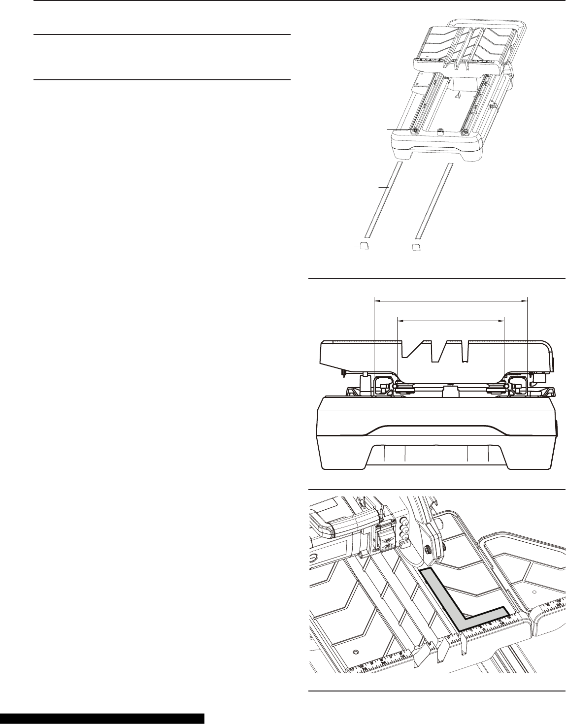
Rail Adjustment
NOTE: The saw has been calibrated by the manufacturer.
The following adjustment steps are to be used only when
necessary.
1. Turn off the saw. Remove the two end covers (1) at the
ends of the rails from the end of the rails. Remove the
two top covers (2) of the rails by sliding them out from
the top of the rails (Fig. 39).
2. Loosen the four screws (3) inside each rail so that the
rails may be adjusted.
3. Use a slide caliper or straight ruler to measure the dis-
tance between the two rails at one end of the rails. Make
sure that the distance is 320mm, and then slightly tight-
en the screw at that end of each rail. Follow the same
procedure at the other ends of the rails to adjust the
distance between the rails to 320mm, and slightly tight-
en the screw at that end of each rail (Fig. 40).
4. Place a 90° framing square on the working table against
working-table fence (Fig. 41).
5. Push the working table with the square along the saw
blade to determine if the gap between the framing
square and blade is consistent along the length of the
stroke.
6. If the gap is consistent, rmly secure all eight xing
screws (3). If not, repeat the adjustment steps above
until the gap is consistent.
ADJUSTMENTS
3
2
1
Fig. 39
320
223.38
Fig. 40
Fig. 41

30
WARNING:
For your own safety, read and always observe all safety
precautions listed in operator’s manual and on saw.
Safety Instructions for Basic Operations
WARNING:
Don't allow familiarity (gained from frequent use of your
tile saw) to cause a careless mistake. Always remember
that a careless fraction of a second is enough to cause
a severe injury.
• Never put your ngers or hands in the path of the saw
blade or other cutting tool.
• Never reach behind the cutting tool with either hand for
any reason. Do not reach behind the blade to hold down
the work piece, support the work piece, remove scraps, or
for any other reason.
• Never use a hand position where a sudden slip could
cause the ngers or the hand to move into a saw blade.
Before Each Use Inspect Your Saw
• With the machine disconnected from the power supply,
rotate the blade by hand to make sure that it moves
freely.
• Make sure that the switch is in the OFF position before
plugging the saw into an electrical receptacle.
• If any part is missing, bent, or broken in any way, or any
electrical part does not work properly, turn the saw off and
unplug the saw.
• If the cutting blade is damaged, replace it before operating
the saw.
• Always check for and remove all keys, adjusting wrench-
es, and other tools from the work table before turning on
the saw.
• Make sure that all clamps, fasteners, and locks are tight
and that no parts have excessive play.
• Keep guards in place and in working order.
• Check for damaged parts. Before further use of the tool,
any part that is damaged should be carefully checked to
make sure that it would operate properly and perform its
intended function. Check for proper alignment of moving
parts, binding of moving parts, breakage of parts, mount-
ing, and any other conditions that may affect the tool’s
operation. A guard or other part that is damaged should
be properly repaired or replaced.
• Always keep the blade-securing arbor and collars clean.
• Make sure that the blade-securing bolt is securely tight-
ened with the wrench provided.
OPERATION
• Use the anti-splash rubber guard for every operation for
which it can be used.
• Check that the directional arrow marked on the blade cor-
responds with the rotational direction of the motor as
marked on the blade guard.
• Disconnect power to the saw before servicing, when
changing cutting blade, and cleaning.
Whenever the Saw Blade Is Spinning
• Let the saw blade run freely for a few seconds before cut-
ting a tile piece. If the saw blade makes an unfamiliar noise
or vibrates excessively, switch the saw off immediately
and disconnect it from the power supply. Investigate the
cause or consult the customer service department for ad-
vice. Do not restart the saw until nding and correcting the
problem.
• Always feed work into the blade against the direction of
rotation of the blade.
• Keep children away. All visitors should be kept safe dis-
tance from the work area.
Don’t Force the Tool
• Let the blade reach full speed before starting to cut.
• The saw will do a better job and be safer when it is used at
the rate for which it was designed.
Before Leaving the Saw
• Turn the saw off.
• Wait for blade to stop spinning.
• Unplug the saw.
• Always make the workshop childproof. Disconnect master
switches.
To Reduce the Risk of Injury From Jams, Slips or
Thrown Pieces
Inspect Your Blade
• Choose the right blade for the material and the type of cut-
ting you plan to do.
• Choose and inspect your blade with care.
• To reduce the risk of cutting-tool failure and thrown pieces
of broken blade, use only 10” or 8” wet blades that are
marked for speeds of 5000 rpm or higher.
• Always use unbroken, balanced blades that are designed
to t this saw’s 5/8-inch arbor.
• Do not over-tighten the arbor nut. Use the arbor wrench to
tighten it securely.
• Use the tool only with smooth-edge cutting blades free of
teeth and grooves.
31
Inspect Your Workplace
• Inspect your work area, and keep it clean and safe. Clut-
tered areas and benches invite accidents.
• Avoid slippery oors, whether from oor waxes or spills.
• Never use the saw near ammable liquids, vapors or gases.
• Do not do layout, assembly, or setup work on the table
while the blade is spinning
Plan the Way You Will Push the Work Piece Through.
• Set the cutting tool as low as possible for the cut you’re
planning
• Push the work piece against the rotation of the blade.
Never feed material into the cutting tool from the rear of
the saw.
• Make sure that the off-cut (piece of tile that will be cut off)
has enough room to move sideways. Failure to do so may
result in the off-cut binding against the blade.
• When cutting irregularly shaped work pieces, plan your
work so it will not slip.
• Don’t overreach. Keep proper footing and balance at all
times.
• Always push the work piece all the way past the saw
blade.
Plan Your Cut
• Never cut freehand. Always use either a rip fence or a x-
ture to position and guide the work so that it won’t twist or
bind on the blade.
• Keep the table and surrounding area clear, except for the
tile to be cut.
• Use extra caution with large, very small, or awkward work
pieces.
• Never cut more than one tile at a time.
• Never turn your tile saw “ON” before clearing everything
except the work piece and related support devices off of
the table.
• Never cut pieces too small to be held securely against the
rip fence while leaving enough space for the hands to be a
safe distance from the blade.
• Never allow the blade to run dry. Failure to keep the water
tray topped off will result in possible over-heating of the
diamond blade.
Filling and Draining the Water Tray
CAUTION!
Having too little cooling water in the water tray may
damage the saw blade. Never turn on the machine or
plug in the water pump unless the water level reaches
the lowest scale marked on the water tray.
OPERATION
1. Insert the water plug into the hole of the water tray.
2. Pour ve gallons water into the water tray.
3. Secure the water tray lock (Fig. 42).
4. To insure proper operation, make sure that the water
level in the water tray is at least as high as the lowest
scale marked on the water tray.
5. Do not add chemicals or detergents to the water.
WATER TRAY LOCK CLIPWATER TRAY LOCK CLIP
Fig. 42
To drain the water:
1. Loosen the lock clip.
2. Pull out the water tray approximately 5 inches.
3. Place a ve-gallon bucket beneath the water plug.
4. Remove the water plug
5. Allow the water to ow into the bucket.
Or, you can remove the water pump from the water tray,
loosen the lock clip, remove the water tray, and pour the
water out.
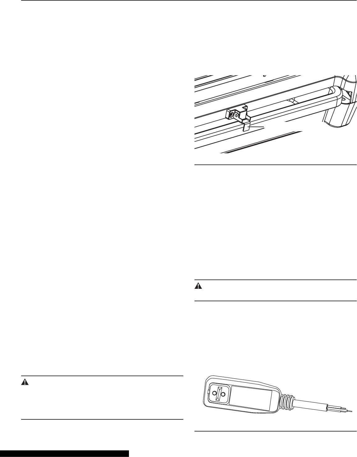
Power Supply
Power tool plugs must match the outlet.
WARNING:
Test before each use.
1. Plug ground-fault-circuit-interruptor (GFCI) into a power
outlet: the indicator should turn on (Fig. 43).
2. Press the test button: the indicator should turn off.
3. Press the reset button again for use. Do not use if the
above test fails.
This device does not protect against electrical shock due to
contact with short circuits or faulty wiring in the power supply.
Fig. 43
32
Cutting Tile and Stone
WARNING:
Do not attempt to cut pieces too small to allow for safe
handling. Avoid awkward hand positions where a sud-
den slip could cause your hand or finger to come in con-
tact with the blade. When cutting any material, make
sure that it is fully supported and that the work piece is
held firmly.
CAUTION:
Make sure that the knob on the blade guard and the
bevel-cut adjustment knob are tightened before operat-
ing the saw.
CAUTION:
Make sure the “Stop/Go” knob is in “STOP” position
before operation.
CAUTION:
To avoid cutting into the work table, make sure that the
lowest position of the blade is less than 9/16” (15mm)
below the surface of work table.
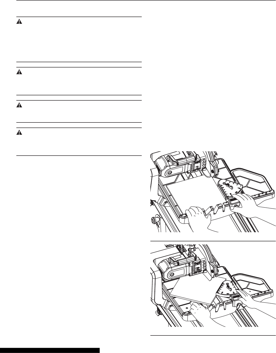
Straight Cut
1. Position the tile on the work table, pressed against the
work-table fence.
2. To use the laser, rst calibrate the laser beam as
described in “Laser Beam Calibration” on page 28, and
make sure that the laser beam is aligned with the cutting
line.
3. Adjust the universal guide to the desired distance from
the blade. Use the scale rules on the work-table fence
for reference.
4. Lift the ON/OFF switch to turn the saw on.
5. Wait until the blade has come up to speed and is thor-
oughly wet.
6. Ease the work table towards the blade to slowly feed
the tile into the blade. Continue pushing until the blade
cuts completely through the tile (Fig. 44).
7. Turn off the saw, pull the work table back, and remove
the cut pieces and any debris.
OPERATION
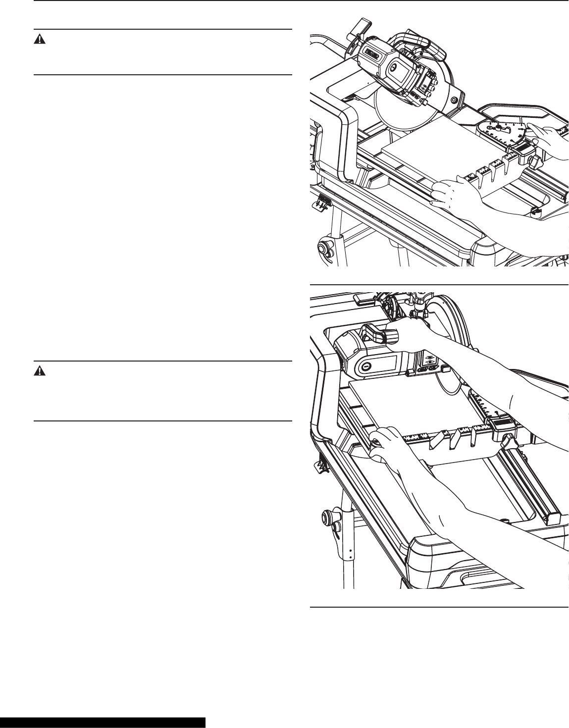
Flat 0°- 45° Angle Cut
1. Position the tile on the work table, pressed against the
work-table fence.
2. To use the laser, rst calibrate the laser beam as
described in “Laser Beam Calibration” on page 28 and
make sure that the laser beam is aligned with the cut-
ting line.
3. Adjust the universal guide to the desired angle as
described in the “Universal Guide Adjustment” on page
27. Make sure that the tile rests against the universal
guide.
4. Adjust the universal guide to the desired distance from
the blade. Use the scale rules on the work-table fence
for reference.
5. Lift the ON/OFF switch to turn the saw on.
6. Wait until the blade has come up to speed and is thor-
oughly wet.
7. Ease the work table towards the blade to slowly feed
the tile into the blade. Continue pushing until the blade
cuts completely through the tile (Fig. 45).
8. Turn off the saw, pull the work table back, and remove
the cut pieces and any debris.
Fig. 44
Fig. 45
33
Bevel Cut (Fig. 41)
WARNING:
The saw is adjustable to only three positions (0°, 22.5°
or 45°). Any other bevel cut will cut into the work table.
1. Adjust bevel cut as described in the “Bevel Cut Adjust-
ment” on page 26.
2. Position the tile on the work table, pressed against the
work-table fence.
3. To use the laser, rst calibrate the laser beam as
described in “Laser Beam Calibration” on page 28, and
make sure that the laser beam is aligned with the cut-
ting line.
4. Adjust the universal guide to the desired distance from
the blade. Use the scale rules on the work-table fence
for reference.
5. Lift the ON/OFF switch to turn the saw on.
6. Wait until the blade has come up to speed and is thor-
oughly wet.
7. Ease the work table towards the blade to slowly feed
the tile into the blade. Continue pushing until the blade
cuts completely through the tile (Fig. 46).
8. Turn off the saw, pull the work table back, and remove
the cut pieces and any debris.
Plunge Cut
WARNING:
Wear safety glasses for laser and do not look directly
into the laser-beam output aperture during plunge cut
operation. The laser beam can be harmful to the eyes.
1. Loosen the depth-adjustment knob and the depth-stop-
adjustment knob. Raise the saw. Set the desired lowest
point of blade using the depth-adjustment knob. (See
Depth Adjustment on page 25 of this manual.)
2. Position the tile on the work table, face down, pressed
against the work table fence.
3. To use the laser, rst calibrate the laser beam as
described in “Laser Beam Calibration” and make sure
that the laser beam is aligned with the cutting line.
4. Align the tile under the saw blade by moving the work
table to the desired position.
5. Lift the ON/OFF switch to turn the saw on, and wait
until the blade has come up to speed and is thoroughly
wet.
6. Plunge the blade into the tile. Do not force the saw or
move the blade too quickly into the tile (Fig. 47).
7. When the cut is complete, lift the saw from the tile.
8. Turn off the saw, pull the work table back, and remove
the cutting pieces and any debris.
OPERATION
Fig. 46
Fig. 47
34
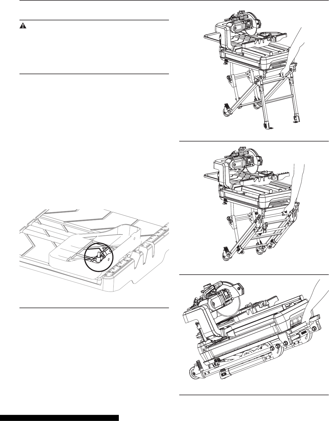
Moving the Saw
WARNING:
Before moving the saw with the stand or folding the
stand, make sure that the work table is locked with the
table lock and that the saw is securely fastened to the
stand with the two screws. Please see “Mounting Your
Saw” on page 17 of this manual. Failure to do so may
result in serious personal injury.
1. Remove the extension table and invert it on the work
table. Align the hole in the extension table with the hole
in work table, pull out the pin attached to the extension
table, and lock the extension table on the work table by
inserting the pin into the holes (Fig. 48).
2. Unlock the wheels on the stand.
3. Hold the handle of the stand rmly, lift the stand, and
make sure that the two legs without wheels are about
1/2 inch above the ground (Fig. 49).
4. The stand may also be fully or partially folded, as shown
in Fig. 50 and Fig. 51. To fold the stand, please see
“Closing the Stand” on page 14.
5. Move the stand carefully to the desired location (if the
legs are folded, unfold the legs), and put it down gently
until the two legs without wheels contact the ground.
6. Lock the two wheels of the stand.
Fig. 48
OPERATION
Fig. 49
Fig. 50
Fig. 51
35
Maintenance
CAUTION!
For your safety, turn off the power switch and unplug
the saw from the power source before performing any
maintenance or cleaning. If the power cord becomes
damaged in any way, replace it immediately with an ap-
proved cord. When cleaning the saw, DO NOT SERVICE
the electric motor’s internal components yourself. Con-
tact an authorized service center.
Periodic maintenance of your tile saw allows for long life and
trouble-free operation. The saw can generate considerable
quantities of cutting residue. A cleaning, lubrication, and
maintenance schedule should be maintained.
As a common-sense and preventative maintenance prac-
tice, follow these recommended steps:
• Clean the entire saw, except electrical parts, with fresh
water after each use.
• Pump clean, fresh water for 1 minute through the water
pump and blade-guard assembly to safeguard against
slurry build-up and clogging.
• Inspect the diamond blade for it is overall integrity. Check
the rim for wear or damage.
• Use a soft cloth to clean the water and dust on the
machine.
• Keep the ventilation slots of the motor clean to prevent
overheating of the motor.
CAUTION:
Never use water or any other chemical liquids for clean-
ing the electrical parts of the machine.
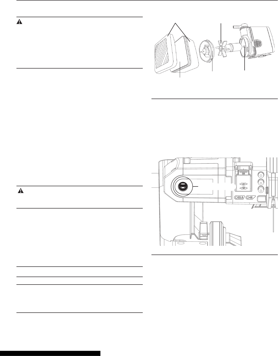
Cleaning the Water Pump
Remove the front-plate accessory and remove the sponge.
Turn the impeller lid counterclockwise until the raised rib of
the impeller lid disengages from the groove. Remove the
impeller lid and impeller, and use a small brush or stream of
water to clean any debris.
Re-assemble the pump, referring to Fig. 52.
NOTE: The pump shaft cannot be removed.
NOTE: If the volume of water pumped by the water pump is
reduced or none after cleaning the water pump, replace the
water pump or have it repaired by a qualied service profes-
sional.
MAINTAINING YOUR SAW
Sponge
Impeller
Lid
Impeller
Pump
Shaft
Front Plate
Accessory
Fig. 52
Changing Carbon Brushes (Fig. 53)
Replace the carbon brush on both sides of the motor when
the motor stops running, or the carbon brush is worn out
(only approximate 9/32” or 5/16” (7 or 8mm) in length).
1. Loosen the plastic cap with a screwdriver, and pull out
the worn carbon brushes.
2. Insert new carbon brushes, replace the plastic caps,
and tighten.
Carbon Brush CapCarbon Brush Cap
Fig. 53
36
Item Part Name QuaNtIty
1 Nut Wrench 1
2 Hex Wrench 1
ATTACHMENTS
TROUBLESHOOTING
WARNING:
For your own protection, turn the ON/OFF switch to “OFF,” and always remove the plug from power-source outlet
before troubleshooting.
TROUBLE PROBABLE CAUSE SOLUTION
Motor stops running There is no power to the electrical outlet. Make sure that the outlet has power.
Low voltage. Check that the power source voltage is 120V.
Plugs aren’t fully connected to the power
source.
Verify that the plugs are securely connected.
Switch isn’t “ON.” Lift the ON/OFF switch to turn the saw on.
The carbon brushes have worn out
completely.
Replace the carbon brushes.
GFCI is tripped. Press the ON/OFF switch down to turn the
saw off; reset the button on the GFCI.
Overload protector tripped. Press the overload-protector switch to restart
the saw.
The water pump cannot
inject water
The water-pump plug is not rmly connected
to the saw receptacle.
Connect the water-pump plug to the saw
receptacle.
There is not enough water in the water tray. Make sure that the water-pump intake is fully
immersed in water.
The water hose is loose or off. Reconnect the water hose to the pump.
The water valve is in “OFF” position. Turn the valve to the “ON” position.
The water hose or water nozzle is jammed. Clean the water hose or water nozzle, or
replace them.
The water pump lter is too dirty. Clean the water-pump lter.
The water pump is damaged. Replace the water pump.
LED Lights/Laser Beam
projection is hard to see
Light in work area is too bright. Move the machine to a work area where the
light isn’t as bright.
Dust or water is on the laser-aperture cover or
on the surface of LED lights.
Wipe the dust or water off with a clean, soft
cloth.
LED Lights/Laser beam
projection doesn’t work
The LED Lights /LASER switch isn’t turned
on.
Turn on the LED/LASER switch.
Frequent tripping of
overload protector
Rapid feeding of material into the cutting
blade
Feed the material more slowly into the
cutting blade
Low voltage and heavy load When cutting extremely dense materials,
make sure that power supply voltage is
exactly 120 V
37
EXPLODED DRAWINGS AND PARTS LISTS
1
2
4
5
6
3
12
11
14
15
21
20
19
22
18
13
17
16
24
23 30
25
29
28
27
26
31
32
36
8
9
10
7
48
49
35
33
34
39
40
41
42
43
44
45
46
47
38
37
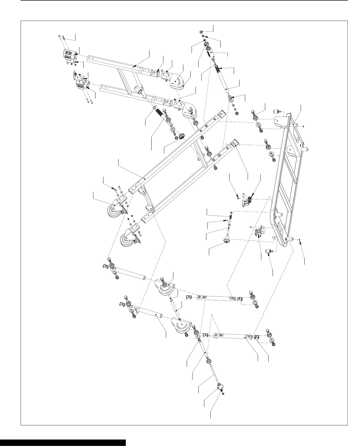
WTS2000L Tile Saw Stand

38
EXPLODED DRAWINGS AND PARTS LISTS
Key
No.
Part No. Description QTY. Key
No.
Part No. Description QTY.
1 6106501 Table Frame 1 25 6106525 M5X10 mm Bolt 6
2 6106502 M8X5 mm Hex Head Bolt 8 26 6106526 Compression Spring 1
3 6106503 Plug for Spring Bushing 2 27 6106527 Rivet 1
4 6106504 Spring Bushing 1 28 6106528 Stop Rod 1
5 6106505 Crossbar Spring 1 29 6106529 Lock Knob 1
6 6106506 Lock Sleeve 1 30 6106530 Right Foot Cushion 1
7 6106507 Nut 14 31 6106531 Upper Support Tube End Cap 6
8 6106508 Nut Cover 23 32 6106532 Upper Support of Leg 2
9 6106509 M8 Washer 30 33 6106533 Spring 1
10 6106510 Nut Bushing 23 34 6106534 Knob 1
11 6106511 Left Connection Bracket 1 35 6106535 Position Rod 1
12 6106512 Right Connection Bracket 1 36 6106536 Plastic Bushing 1
13 6106513 M6X4 mm Bolt 4 37 6106537 Washer 2
14 6106514 Support Tube End Cap 2 38 6106538 Lower Support of Leg 2
15 6106515 Tilted Support Tube Assembly 2 39 6106539 Pull Rod Bushing 1
16 6106516 Tightening Nut 1 40 6106540 Pull Rod 1
17 6106517 Stop Bolt of Tilted Support (M24X3
mm)
1 41 6106541 Double Joint 2
18 6106518 M6X40 mm Bolt 4 42 6106542 Wheel Assembly 2
19 6106519 Left Foot 1 43 6106543 M6X35 mm Bolt 4
20 6106520 Left Mounting Foot 1 44 6106544 Lower Support Assembly 2
21 6106521 Right Mounting Foot 1 45 6106545 Pull Rod of Crossbar 1
22 6106522 Right Foot 1 46 6106546 M8X45 mm Hex Head Bolt 1
23 6106523 Left Foot Cushion 1 47 6106547 M6 Nut 12
24 6106524 Lower Support Tube End Cap 2 48 6106548 Knob 2
49 6106549 Circlip 2
WTS2000L Tile Saw Stand Parts List
39
EXPLODED DRAWINGS AND PARTS LISTS
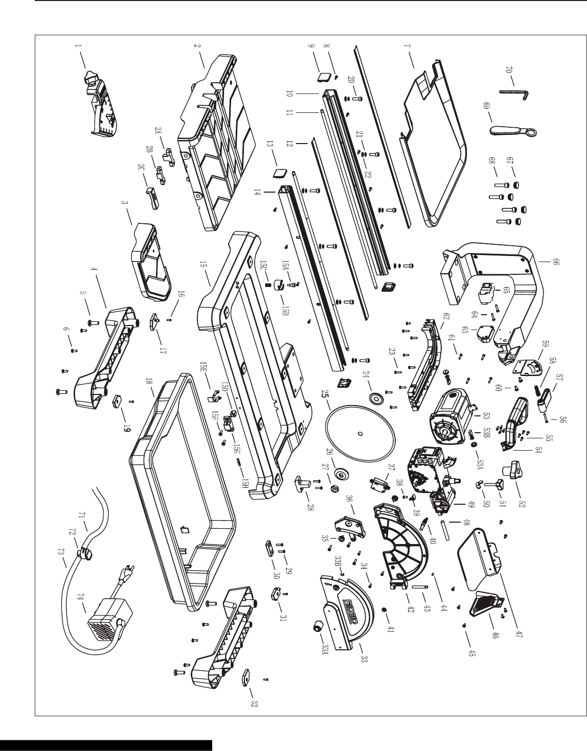
WTS2000L Tile Saw

40
EXPLODED DRAWINGS AND PARTS LISTS
WTS2000L Tile Saw Parts List
Key
No.
Part No. Description QTY. Key
No.
Part No. Description QTY.
1 6106001 Universal Guide 1 33B 6106046 Check Ring 1
2 6106002 Work Table 1 34 6106047 Bolt 6
2A 6106003 Stop Block 1 of Work Table 1 35 6106048 Laser Beam Adjustment Knob 2
2B 6106004 Stop Block 2 of Work Table 1 36 6106049 Laser Beam Guard 1
2C 6106005 Table Lock 1 37 6106050 Laser Assembly 1
3 6106006 Extension Table 1 38 6106051 Bolt 1
4 6106007 Frame Support 2 39 6106052 Connection of LED Control Box 1
5 6106008 M10X30 mm Bolt 4 40 6106053 Water Nozzle 1
6 6106009 M6X16 mm Bolt 6 41 6106054 Flat Nut 1
7 6106010 Extension Water Tray 1 42 6106055 Inner Blade Guard 1
8 6106011 Bolt 10 43 6106056 Rotary Spindle of Blade Guard 1
9 6106012 End Cover 1 of Rail 2 44 6106057 Tightening Bolt 1
10 6106013 Left Rail 1 45 6106058 Bolt 7
11 6106014 Rail Shaft 2 46 6106059 Anti-Splash Guard 2 1
12 6106015 Top Cover of Rail 2 47 6106060 Anti-Splash Guard 1 1
13 6106016 End Cover 2 of Rail 2 48 6106061 Rotary Spindle of 57 1
14 6106017 Right Rail 1 49 6106062 Gear Box 1
15 6106018 Frame 1 50 6106063 Wing Nut 1
15A 6106019 Stop Pin 1 51 6106064 Depth Adjustment Knob 1
15B 6106020 Stop/Go Knob of Work Table 1 52 6106065 Depth Stop Adjustment Knob 1
15C 6106021 Stop Spring 1 53 6106066 Motor Unit 1
15D 6106022 Stop Spring Plate of Water Tray 1 53A 6106067 Carbon Brush Cap 2
15E 6106023 Lock Clip of Water Tray 1 53B 6106068 Carbon Brush 2
15F 6106024 Bolt 2 54 6106069 Handle 1
15G 6106025 Stop Block of Water Tray 1 55 6106070 Bolt 8
15H 6106026 Stop Pin of Watery Tray 1 56 6106071 Bolt 1
16 6106027 Self-Tapping Screw 4 57 6106072 Bevel Cut Adjustment Knob 1
17 6106028 Cover Board 1 of Frame Support 1 58 6106073 Tightening Bolt 1
18 6106029 Water Tray 1 59 6106074 Dial of Bevel Cut Adjustment 1
19 6106030 Cover Board 2 of Frame Support 1 60 6106075 Bolt 2
20 6106031 M8X25 mm Bolt 8 61 6106076 Bolt Assembly 4
21 6106032 Spring Washer 8 62 6106077 Cover 2 of Supporting Arm 1
22 6106033 Flat Washer 8 63 6106078 LED Control Box 1
23 6106034 Self-Tapping Screw 9 64 6106079 Bolt 2
24 6106035 Inner Flange 1 65 6106080 Wrench Storage Clip 1
25 6106036 Blade 1 66 6106081 Supporting Arm 1
26 6106037 Outer Flange 1 67 6106082 Bolt Cover 4
27 6106038 Shaft Nut 1 68 6106083 Bolt 4
28 6106039 Latch 1 of Extension Water Tray 1 69 6106084 Nut Wrench 1
29 6106040 Bolt 4 70 6106085 Allen Wrench 1
30 6106041 Latch 2 of Extension Water Tray 1 71 6106086 Water Hose 1 1
31 6106042 Cover Board 3 of Frame Support 1 72 6106087 Penstock 1
32 6106043 Cover Board 3 of Frame Support 1 73 6106088 Water Hose 2 1
33 6106044 Outer Blade Guard 1 74 6106089 Water Pump 1
33A 6106045 Knob of Blade Guard 1

41
NOTES

42
NOTES

43
NOTES

44
© 2007 RIDGID, INC.
RIDGID® TILE CUTTER AND TILE SAW
LIMITED THREE YEAR WARRANTY AND
90 DAY SATISFACTION GUARANTEE POLICY
This product is manufactured under license from Ridgid, Inc. by Chervon North
America, Inc. All warranty communications should be directed to Chervon North
America, Inc. at: (toll free) 1-866-9-RIDGID (1-866-974-3443 ) or 1-800-4-RIDGID
(1-800-474-3443).
90-Day Satisfaction Guarantee Policy
During the rst 90 days after the date of purchase, if you are dissatised with the
performance of this RIDGID® tool for any reason, you may return the tool to the
dealer from which it was purchased for a full refund or exchange. To receive a
replacement tool you must present proof of purchase and return all original equip-
ment packaged with the original product. The replacement tool will be covered by
the limited warranty for the balance of the three year warranty.
What is covered under the Limited Three Year Warranty
This warranty covers all defects in workmanship or materials in this RIDGID® tool
for the three year period from the date of purchase. This warranty is specic to this
tool. Warranties for other RIDGID® products may vary.
How to obtain service
For service or parts for this RIDGID® tool, please call (toll free) 1-866-9-RIDGID
or 1-800-4-RIDGID or log onto the RIDGID® website at www.ridgid.com. When
requesting warranty service or parts, you must present proof-of-purchase docu-
mentation that includes the date of purchase. An authorized service center will
repair any faulty workmanship and either repair or replace any defective part, at our
option and at no charge to you.
Important:
To speed up the warranty process, log onto the RIDGID® website at www.ridgid.
com or call 1-866-9-RIDGID or 1-800-4-RIDGID within 30 days of purchase to
register your RIDGID®
tool and validate your warranty. Please keep a copy of your
receipt for your records and to make a claim on your warranty.
What is not covered
This warranty applies only to the original purchaser at retail and may not be transferred.
This warranty only covers defects arising under normal usage and does not cover any
malfunction, failure or defect resulting from misuse, abuse, neglect, alteration, modi-
cation or repair by other than authorized RIDGID® service center for tile cutters and tile
saws. Chervon North America, Inc. makes no warranties, representations or promises
as to the quality or performance of its power tools other than those specically stated
in this warranty.
Additional Limitations
To the extent permitted by applicable law, all implied warranties, including warranties
of MERCHANTABILITY or FITNESS FOR A PARTICULAR PURPOSE, are disclaimed.
Any implied warranties, including warranties of merchantability or tness for a par-
ticular purpose, that cannot be disclaimed under state law are limited to three years
from the date of purchase. Chervon North America, Inc. is not responsible for direct,
indirect, incidental or consequential damages. Some states do not allow limitations
on how long an implied warranty lasts and/or do not allow the exclusion or limitation
of incidental or consequential damages, so the above limitations may not apply to
you. This warranty gives you specic legal rights, and you may also have other rights
which vary from state to state.
Model No. WTS2000L
Serial No. _____________________
The model and serial numbers may be found on a plate attached to the saw at
the rear of the tile saw base. You should record both model and serial number in
a safe place for future use.
Questions or comments? Call:
1-866-9-RIDGID (1-866-974-3443) or 1-800-4-RIDGID (1-800-474-3443)
or go on-line at www.ridgid.com.
Please have your Model Number and Serial Number on hand when calling.
