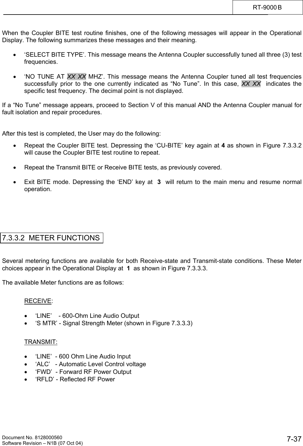
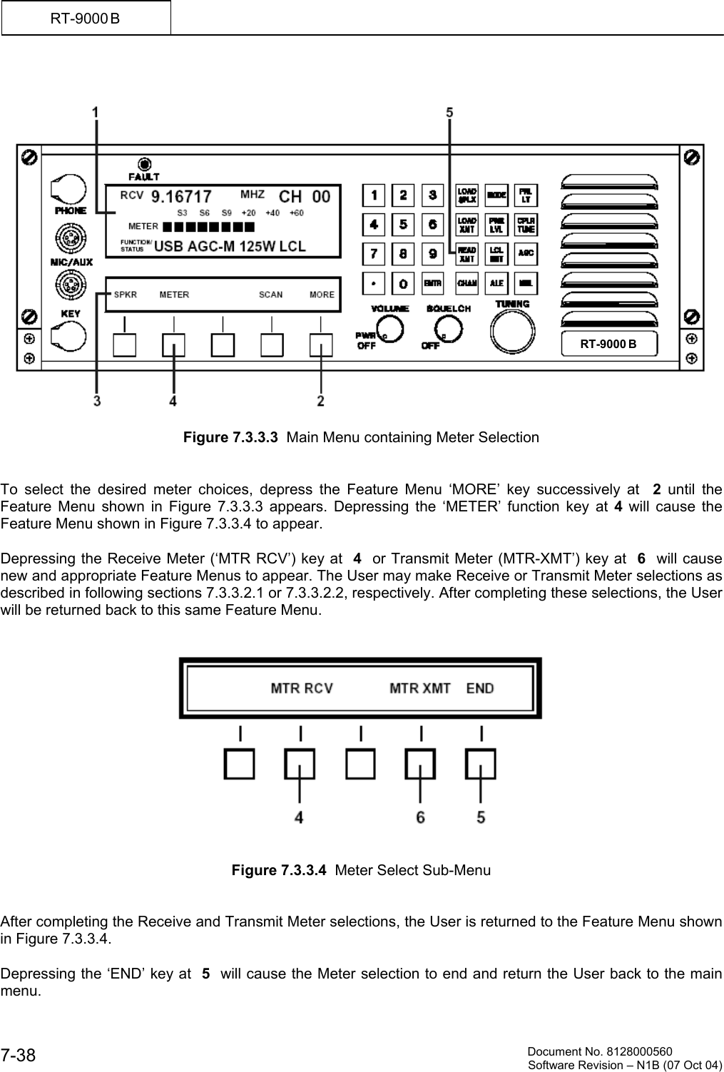
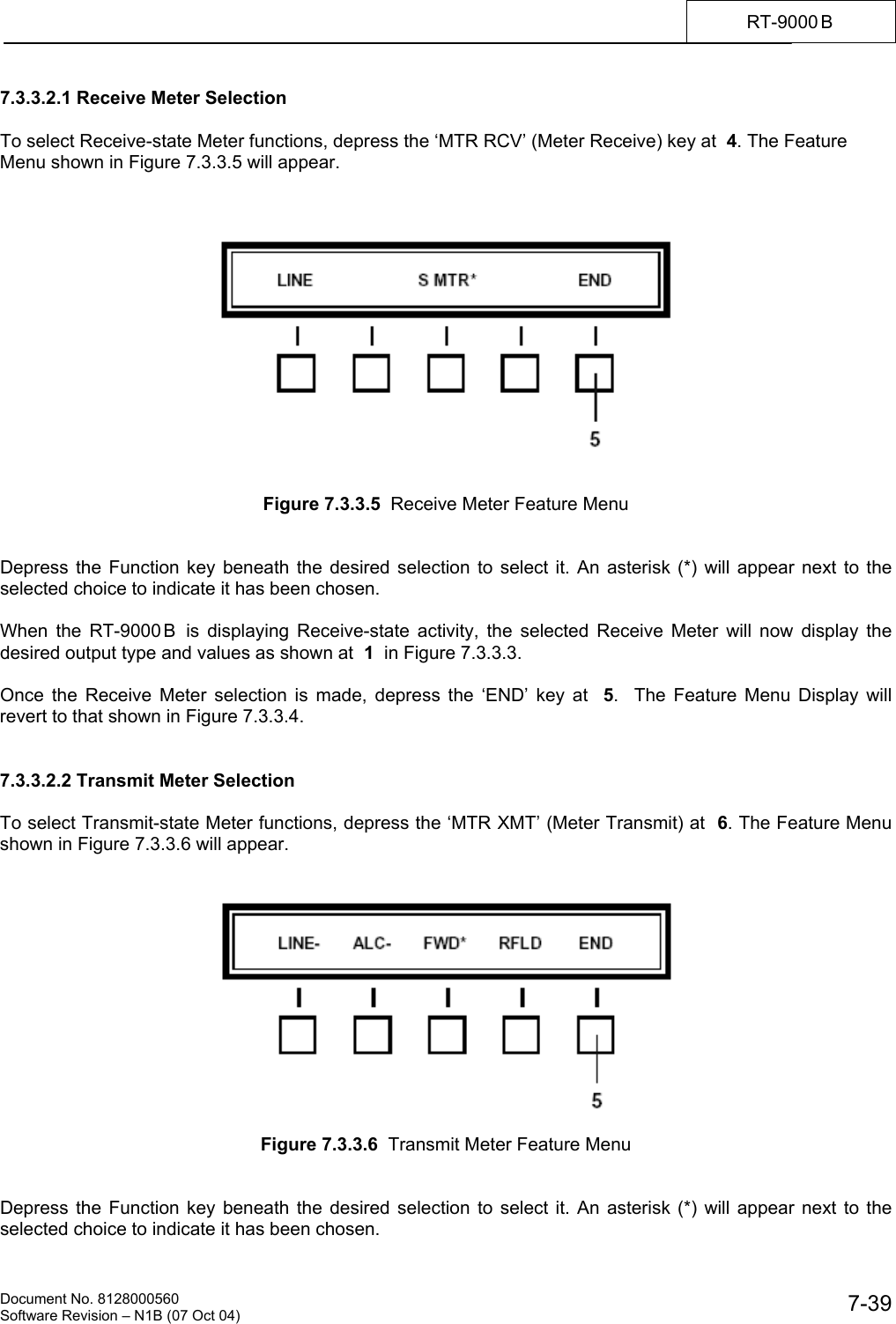
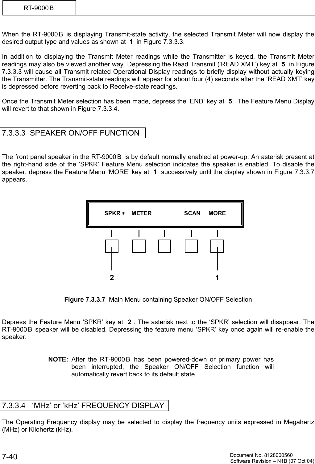
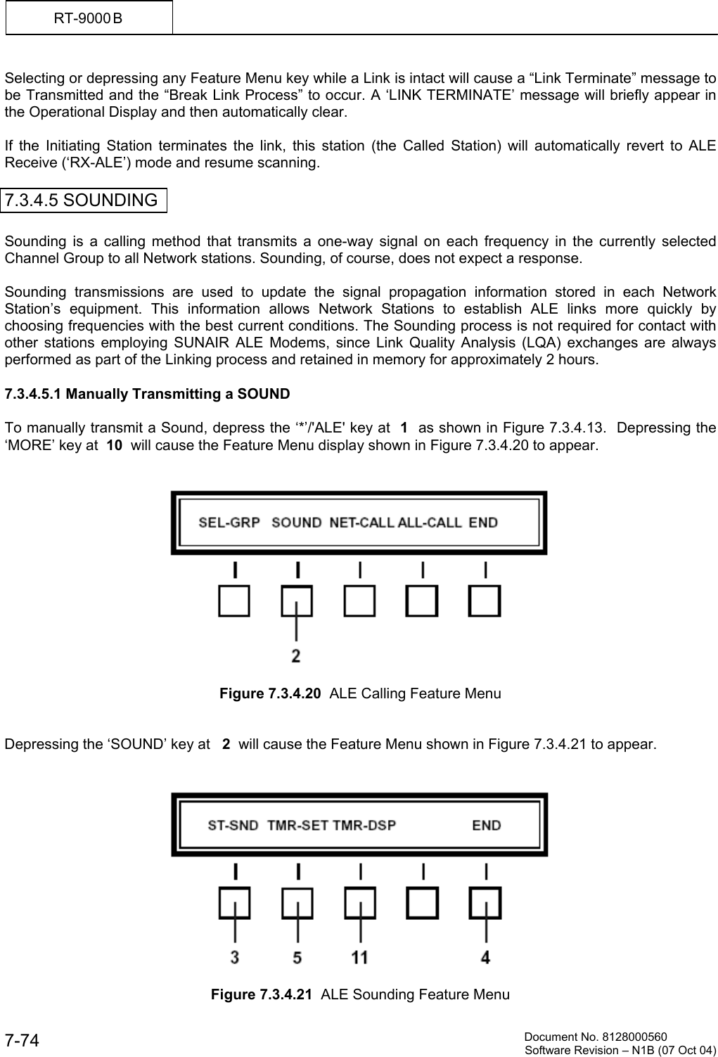
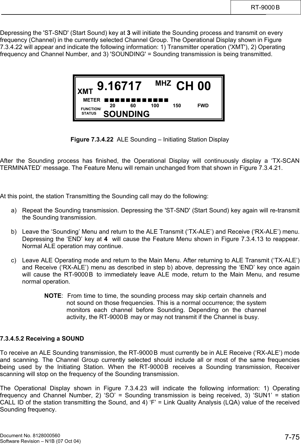
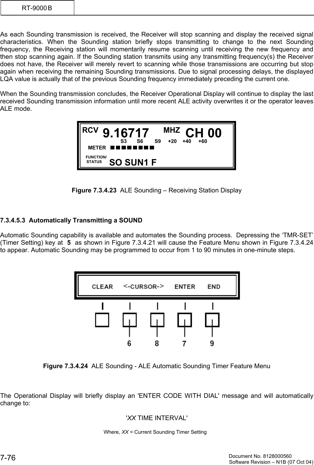
Riimic Sunair Electronics RT-9000 HF TRANSCEIVER User Manual
Riimic, LLC dba Sunair Electronics HF TRANSCEIVER Users Manual
UserManual.wiki
>
Riimic Sunair Electronics
>
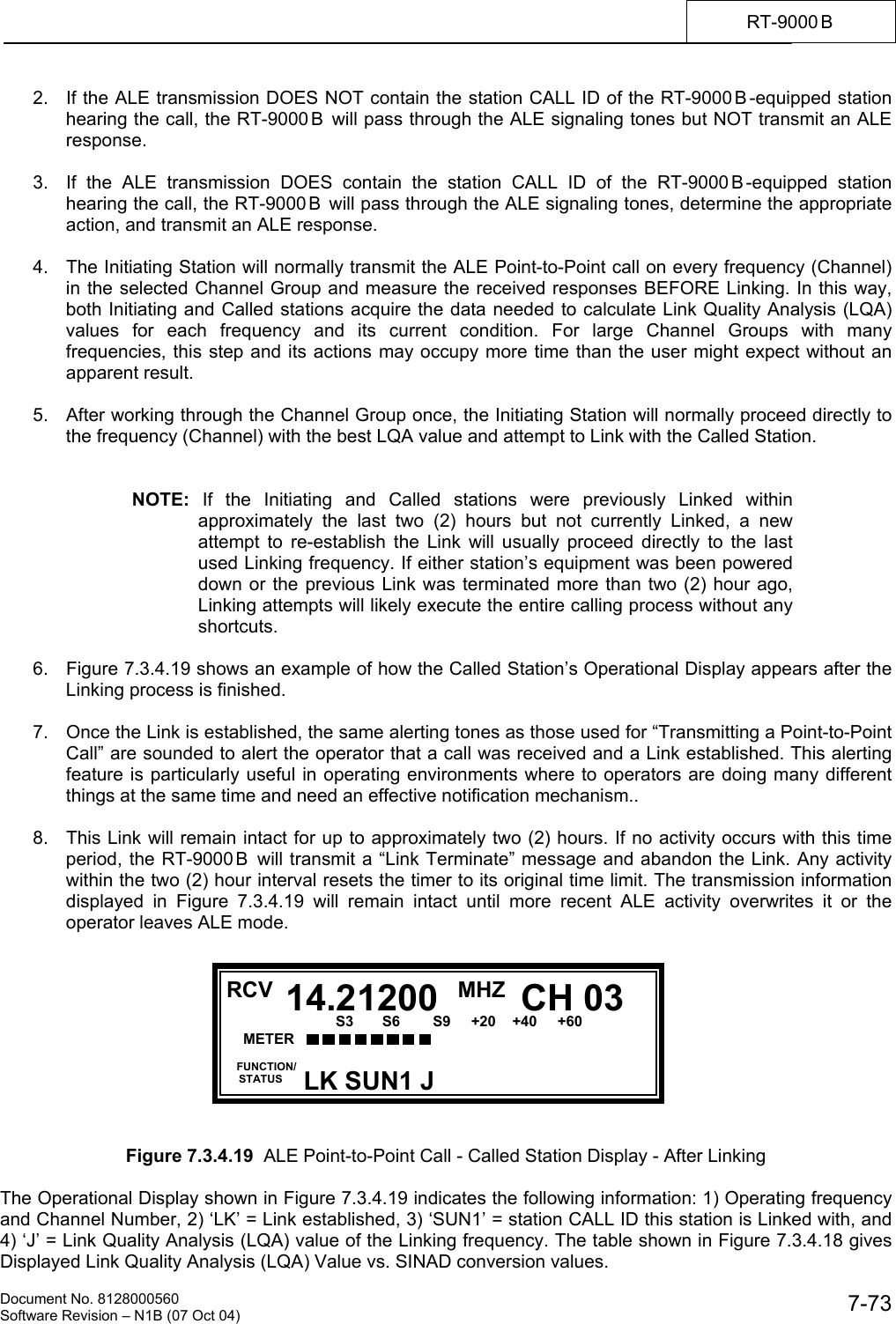
RT-9000 User Manual
>
Users Manual
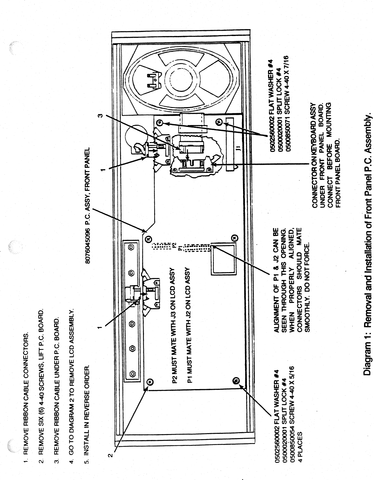
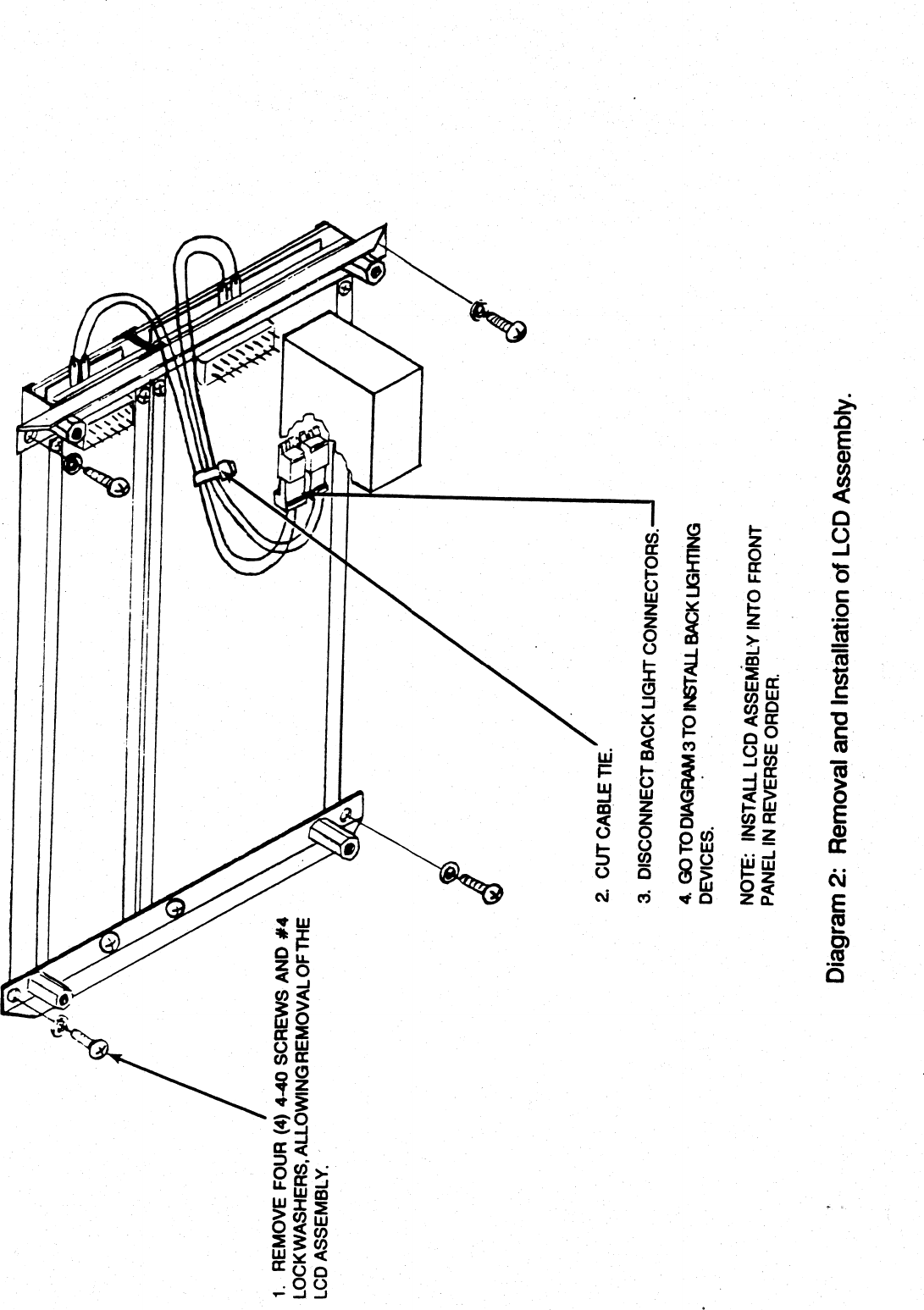
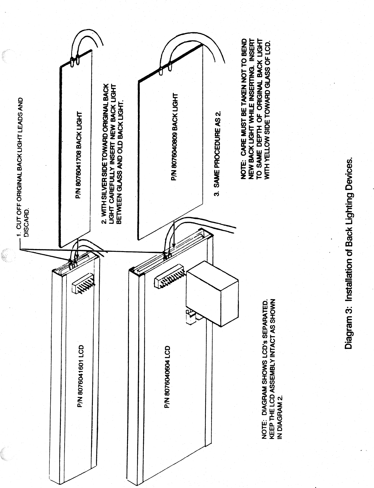
Contents
1.
Repair Manual
2.
Users Manual
3.
User Installation Manual
Users Manual
Navigation menu
Upload a User Manual
Namespaces
Wiki Guide
HTML
PDF
Info
Views
User Manual
Discussion / Help
Navigation